

Page 1
i
Version 1.1
G52-MA00571
MS-6501 (v1.X) ATX Mainboard
MSI
MICRO-STAR INTERNATIONAL
K7D Master
K7D Master-L
Page 2
ii
Manual Rev: 1.1
Release Date: March 2002
FCC-B Radio Frequency Interference Statement
This equipment has been tested and found to comply with the limits for a class
B digital device, pursuant to part 15 of the FCC rules. These limits are designed
to provide reasonable protection against harmful interference when the equipment is operated in a commercial environment. This equipment generates, uses
and can radiate radio frequency energy and, if not installed and used in accordance with the instruction manual, may cause harmful interference to radio
communications. Operation of this equipment in a residential area is likely to
cause harmful interference, in which case the user will be required to correct
the interference at his own expense.
Notice 1
The changes or modifications not expressly approved by the party responsible for compliance could void the user’s authority to operate the equipment.
Notice 2
Shielded interface cables and A.C. power cord, if any, must be used in order to
comply with the emission limits.
VOIR LA NOTICE D’INSTALLATION AVANT DE RACCORDER AU
RESEAU.
Micro-Star International MS-6501
Tested to comply
with FCC Standard
For Home or Office Use
Page 3

iii
Edition
March 2002
Copyright Notice
The material in this document is the intellectual property of MICRO-STAR
INTERNATIONAL. We take every care in the preparation of this document,
but no guarantee is given as to the correctness of its contents. Our products
are under continual improvement and we reserve the right to make changes
without notice.
Trademarks
All trademarks are the properties of their respective owners.
Intel® and Pentium® are registered trademarks of Intel Corporation.
PS/2 and OS®/2 are registered trademarks of International Business Machines
Corporation.
Windows® 95/98/2000/NT/XP are registered trademarks of Microsoft
Corporation.
Netware® is a registered trademark of Novell, Inc.
Award® is a registered trademark of Phoenix Technologies Ltd.
AMI® is a registered trademark of American Megatrends Inc.
Revision History
Revision Revision History Date
V1.1 Add LAN, USB ports, March 2002
JUSB1
Page 4

iv
1. Read the safety instructions carefully.
2. Save this User’s Guide for possible use later.
3. Keep this equipment away from humidity.
4. Lay this equipment on a stable and flat surface before setting it up.
5. The openings on the enclosure are used for air convection and to prevent
the equipment from overheating. Note: Do not cover the openings.
6. Make sure that the power voltage is within its safety range and has been
adjusted properly to the value of 110/220V before connecting the equipment to the power inlet.
7. Place the power cord in a way that people are unlikely to step on it. Do not
place anything on the power cord.
8. Always unplug the power cord before inserting any add-on card or module.
9. All cautions and warnings on the equipment should be noted.
10. Never pour any liquid into the opening that could damage the equipment
or cause an electrical shock.
11. If any of the following situations arises, get the equipment checked by a
service personnel:
z the power cord or plug is damaged
z liquid has penetrated into the equipment
z the equipment has been exposed to moisture
z the equipment has not work well or you can not get it work according
to User’s Guide
z the equipment was dropped and damaged
z the equipment has obvious signs of breakage
12. Do not leave the equipment in an unconditioned environment with a storage temperature of 600 C (1400F) or above, which may damage the
equipment.
Safety Instructions
CAUTION: To prevent explosion caused by improper battery
replacement, use the same or equivalent type of battery recommended
by the manufacturer only.
Page 5

v
CONTENTS
Chapter 1. Introduction ............................................................................ 1-1
Mainboard Specification ...................................................................... 1-2
Mainboard Layout ............................................................................... 1-4
Quick Components Guide .................................................................... 1-6
MSI Special Features ........................................................................... 1-7
PC Alert™ III ................................................................................. 1-7
Fuzzy Logic™ III ........................................................................... 1-8
D-LED™ & D-Bracket™ ................................................................ 1-9
Chapter 2. Hardware Setup ...................................................................... 2-1
Central Processing Unit: CPU .............................................................. 2-2
CPU Installation Procedures ......................................................... 2-3
Thermal Issue for CPU .................................................................. 2-4
CPU Core Speed Derivation Procedure ......................................... 2-5
CPU Clock Frequency Selection: JFSB1 ........................................ 2-5
Recommended Computer Case and Axial Fans ............................. 2-6
Memory Installation ............................................................................. 2-7
DDR Module Combination ............................................................ 2-8
DDR Module Installation Procedures ........................................... 2-9
Power Supply ..................................................................................... 2-10
ATX 20-Pin Power Supply: JPWR1 ............................................. 2-10
ATX 12V Power Connector: J4 .................................................... 2-11
Back Panel .......................................................................................... 2-12
Mouse Connector: JKBMS1 ....................................................... 2-12
Keyboard Connector: JKBMS1 ................................................... 2-13
Serial Port Connector: COM A & COM B ................................... 2-13
LAN Connector ........................................................................... 2-14
USB Connectors .......................................................................... 2-14
Parallel Port Connector: LPT1 ...................................................... 2-15
Page 6

vi
Audio Port Connectors ............................................................... 2-16
Joystick/Midi Connectors ........................................................... 2-16
Connectors ......................................................................................... 2-17
Floppy Disk Drive Connector: FDD1 ........................................... 2-17
Hard Disk Connectors: IDE1 & IDE2 ........................................... 2-18
Case Connector: JFP1 & JFP2 ..................................................... 2-19
CD-In Connector: JCD1 ............................................................... 2-20
Aux Line-In Connector: JAUX1 .................................................. 2-20
Modem-In Connector: JPHN1 ..................................................... 2-20
Wake On Ring Connector: JWR1 ................................................ 2-21
Wake On LAN Connector: JWL1 ................................................ 2-21
CPUFAN1/CPUFAN2/PSFAN1/SYSFAN/NBFAN1 ..................... 2-22
USB Front Panel Connector: JUSB1 ............................................ 2-23
D-Bracket™ Connector: JDB1 ..................................................... 2-24
IrDA Infrared Module Connector: JIR1 ....................................... 2-25
Chassis Intrusion Switch Connector: JCI1 .................................. 2-26
Jumpers .............................................................................................. 2-27
Clear CMOS Jumper: JBAT1 ........................................................ 2-27
Slots ................................................................................................... 2-28
AGP (Accelerated Graphics Port) Pro Slot .................................. 2-28
PCI Slots ...................................................................................... 2-28
PCI Interrupt Request Routing .................................................... 2-29
Chapter 3. AWARD® BIOS Setup ............................................................ 3-1
Entering Setup ...................................................................................... 3-2
Control Keys ................................................................................. 3-2
Getting Help .................................................................................. 3-3
The Main Menu ................................................................................... 3-4
Standard CMOS Features .................................................................... 3-6
Advanced BIOS Features .................................................................... 3-8
Advanced Chipset Features ............................................................... 3-11
Page 7

vii
Integrated Peripherals ........................................................................ 3-14
Power Management Setup ................................................................. 3-19
PNP/PCI Configurations ..................................................................... 3-23
PC Health Status ................................................................................ 3-25
Frequency/Voltage Control ................................................................ 3-26
Load Fail-Safe/Optimized Defaults ..................................................... 3-27
Set Supervisor/User Password ........................................................... 3-28
Appendix A: Installing Drivers .................................................................A-1
Driver Installation for Windows 2000/XP ............................................ A-2
Installing Intel Ethernet LAN Driver ................................................... A-3
Installing AMD 762 Chipset Driver .....................................................A-4
Installing AMD EIDE Driver ............................................................... A-6
Installing AMD 768 Chipset Driver .....................................................A-9
LargePageMinimum .......................................................................... A-10
AMD AC97 Audio Driver ................................................................. A-11
Appendix B: USB 2.0 Controller Card ......................................................B-1
Acknowledgements ............................................................................ B-2
Introduction ........................................................................................ B-4
Features ........................................................................................ B-4
System Requirements ................................................................... B-5
Hardware Installation .......................................................................... B-6
Software Installation ........................................................................... B-7
Windows® 98SE Setup ................................................................. B-7
Windows® ME Setup ................................................................. B-14
Windows® 2000 Setup ................................................................ B-16
Windows® XP Setup .................................................................. B-18
Glossary .................................................................................................... G-1
Page 8

1-1
Getting Started
Chapter 1. Getting Started
1
Getting Started
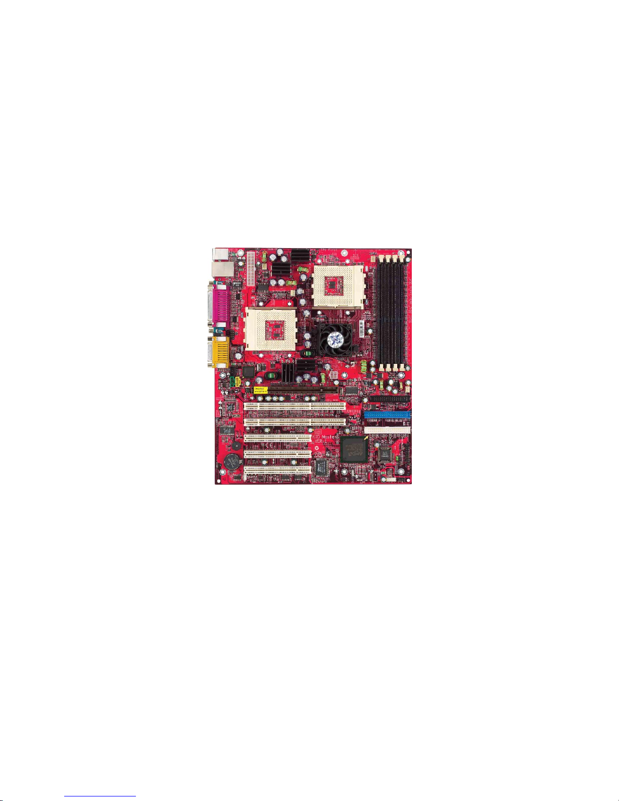
Thank you for your purchase of the MSI mainboard. The MS-6501 V1.X
ATX mainboard is an excellent computer mainboard based on the innovative
AMD-762™ & 768™ chipsets, which supports the dual AMD Athlon™ MP
processors series and provides you a cost-effective solution to meet your
needs.
TOPICS
Mainboard Specification 1-2
Mainboard Layout 1-4
Quick Components Guide 1-6
MSI Special Features 1-7
Page 9

1-2
Chapter 1
CPU
Supports dual Socket A (Socket-462) for AMD Athlon™ MP processors
Supports Athlon MP 2100+ or higher
Chipset
AMD-762™ chipset (949 BGA)
- Supports 200MHz High speed, split transaction system bus
- A 66/33MHz 64/32bit PCI 2.2 compliant bus interface supports up to seven
bus masters
- The 66MHz AGP 2.0 compliant interface supports 1x, 2x, and 4x data transfer
mode
AMD-768™ chipset (492 BGA)
- Host (primary) PCI bus utilizes a 66 MHz, 32-bit interface.
- Enhanced IDE controller (through AT A100)
- LPC bus to connect peripherals such as super IO and BIOS
- Extensive ACPI-compliant power management logic
- IO APIC controller
- AC97 soft audio controller
Clock Generator
100/133MHz clocks are supported (266 MHz Internal System Bus)
Main Memory
Supports eight memory banks using four 184-pin unbuffered DDR DIMMs
Supports DDR SDRAM DIMM
Supports a maximum memory size of 4GB (registered DDR only).
Slots
One AGP (Accelerated Graphics Port) Pro Slot (4X mode)
T wo 64-bit/66MHz and three 32-bit/33MHz PCI Slots
Supports 3.3v/5v PCI bus interface
Mainboard Specification
Note: Because of limitations imposed by the personal computer architecture
and BIOS, the user-accessible memory is less than 4 Gbytes even if 4 Gbytes
of physical memory is installed.
Page 10

1-3
Getting Started
On-Board IDE
An IDE controller on the AMD-768™ chipset provides IDE HDD/CD-ROM
with PIO, Bus Master and Ultra DMA 100 operation modes
Can connect up to four IDE devices
Audio
Chip Integrated
- Direct Sound AC97 Audio
On-Board Peripherals
On-Board Peripherals include:
- 1 floppy port supports 2 FDDs with 360K, 720K, 1.2M, 1.44M and
2.88Mbytes.
- 2 serial ports (COM A + COM B)
- 1 parallel port supports SPP/EPP/ECP mode
- 4 USB ports (2 Rear Connectors / 2 Front Pin Headers)
- 1 IrDA/HP connector for SIR/CIR/FIR/ASKIRHPSIR
- 1 audio/game port
Network (K7D Master-L)
Intel® 82551QM LAN Controller
- Integrated IEEE802.3 10-BaseT & 100-BaseTX PHY
BIOS
The mainboard BIOS provides “Plug & Play” function which detects the
peripheral devices and expansion cards of the board automatically.
The mainboard provides a Desktop Management Interface (DMI) function
which records your mainboard specifications.
Dimension
A TX Form Factor: 30.5cm x 25.2cm
Mounting
9 mounting holes
Others
PC Alert System Hardware Monitor
Suspends to RAM/Disk
Fuzzy Logic
Page 11
1-4
Chapter 1
Mainboard Layout
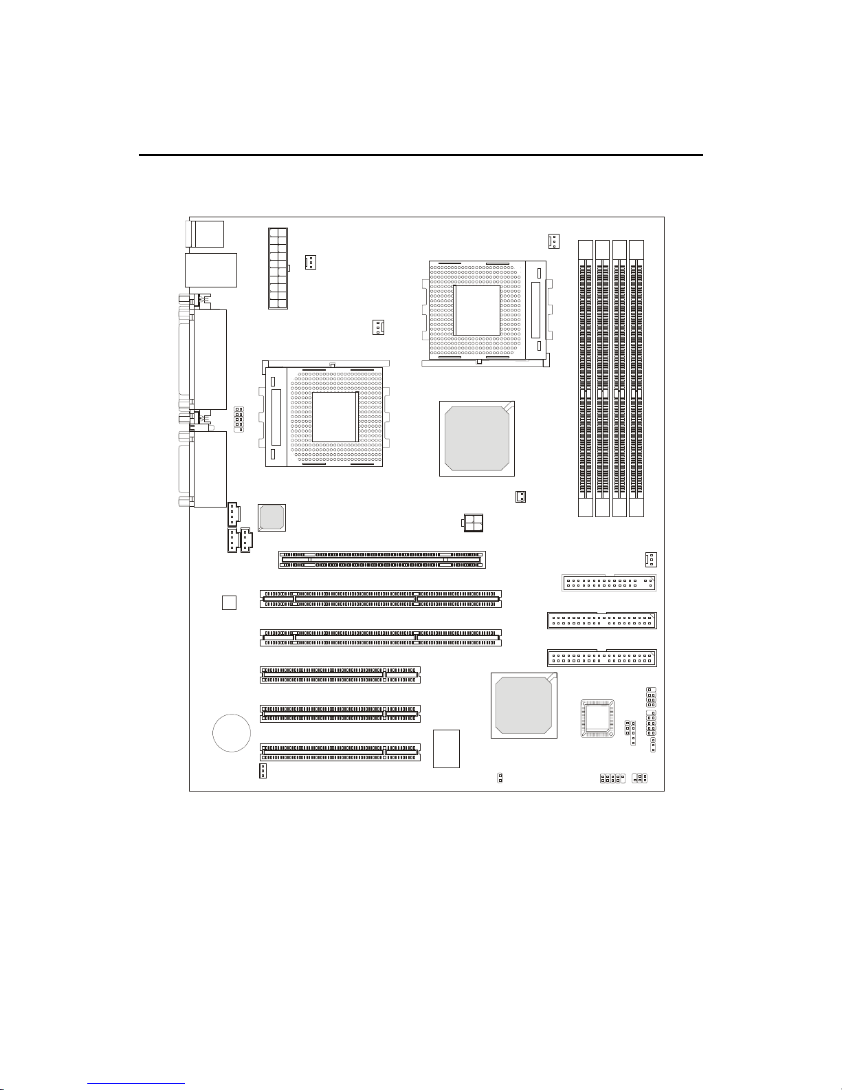
K7D Master-L A TX Mainboard
(MS-6501 v1.X)
BATT
+
Codec
AMD
762
AMD
768
ATX
Power Supply
JUSB1
J
B
A
T
1
JCI
JIR1
BIOS
32-bit PCI Slot 1
64-bit PCI Slot 1
64-bit PCI Slot 2
32-bit PCI Slot 2
32-bit PCI Slot 3
IDE 1
IDE 2
CPUFAN2
CPUFAN1
PSFAN1
SYSFAN
J4
NBFAN1
W
i
n
b
o
n
d
W
8
3
6
2
7
H
F
-
A
W
Top : mouse
Bottom: keyboard
Top: LAN Jack
Bottom: USB
ports
FDD1
Intel
82551QM
S
O
C
K
E
T
4
6
2
S
O
C
K
E
T
4
6
2
Top : Parallel Port
Bottom:
COM A
COM B
JWL1
JWR1
J
F
P
1
J
F
P
2
JFSB1
JCD1
JPHN1
JAUX1
Top :
Game port
Bottom:
Line-Out
Line-In
Mic
D-LED
D
D
R
1
D
D
R
2
D
D
R
3
D
D
R
4
AGP Pro Slot
JDB1
Page 12
1-5
Getting Started
BATT
+
Codec
AMD
762
AMD
768
ATX
Power Supply
JUSB1
J
B
A
T
1
JCI
JIR1
BIOS
32-bit PCI Slot 1
64-bit PCI Slot 1
64-bit PCI Slot 2
32-bit PCI Slot 2
32-bit PCI Slot 3
IDE 1
IDE 2
CPUFAN2
CPUFAN1
PSFAN1
SYSFAN
J4
NBFAN1
W
i
n
b
o
n
d
W
8
3
6
2
7
H
F
-
A
W
Top : mouse
Bottom: keyboard
USB ports
FDD1
S
O
C
K
E
T
4
6
2
S
O
C
K
E
T
4
6
2
Top : Parallel Port
Bottom:
COM A
COM B
JWL1
JWR1
J
F
P
1
J
F
P
2
JFSB1
JCD1
JPHN1
JAUX1
Top :
Game port
Bottom:
Line-Out
Line-In
Mic
D-LED
D
D
R
1
D
D
R
2
D
D
R
3
D
D
R
4
AGP Pro Slot
JDB1
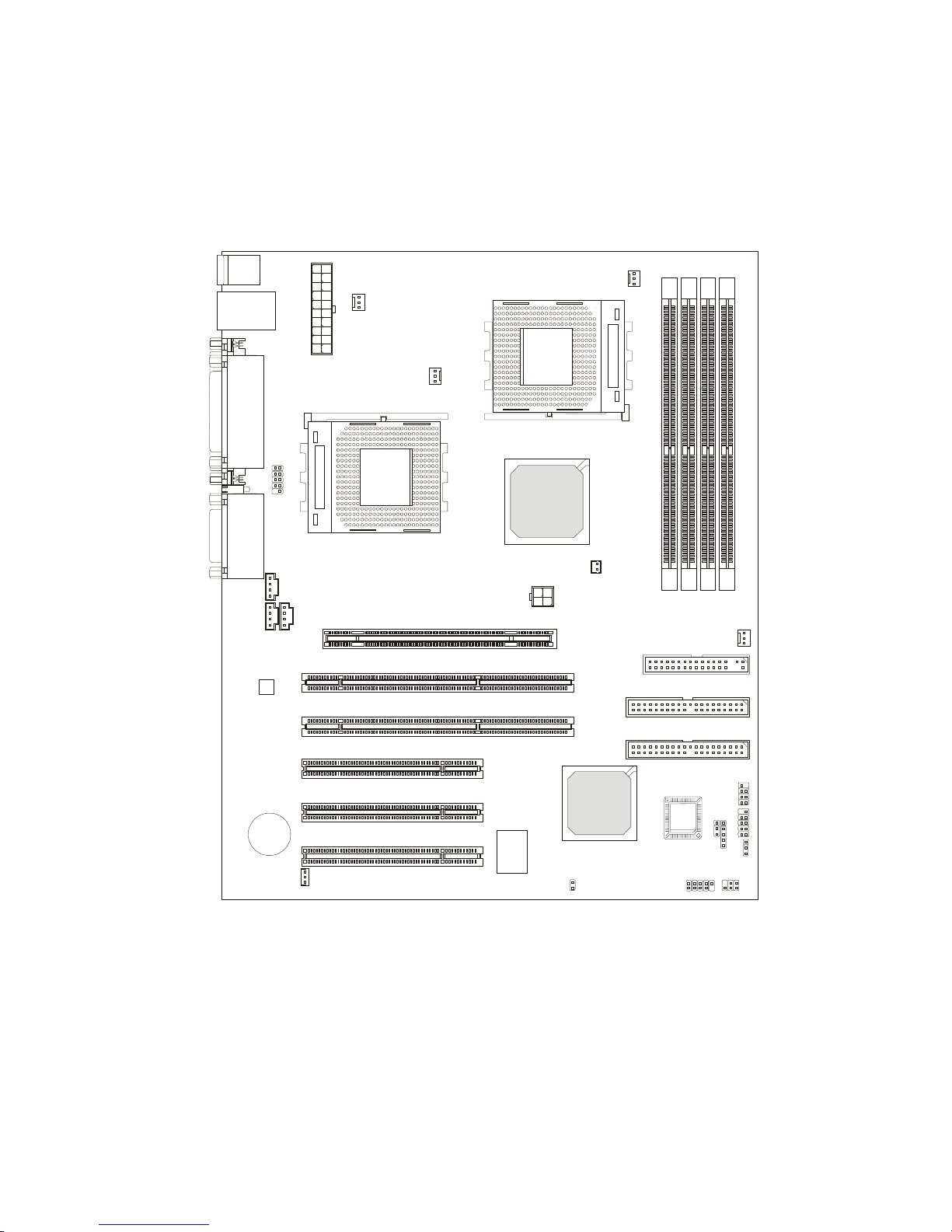
K7D Master A TX Mainboard
(MS-6501 v1.X)
Page 13

1-6
Chapter 1
Quick Components Guide
Component Function Reference
JFSB1 For CPU Clock Frequency See p. 2-6
JPWR1 ATX 20-pin power connector See p. 2-10
J4 ATX 12V power connector See p. 2-11
JKBMS1 Mouse connector See p. 2-12
JKBMS1 Keyboard connector See p. 2-13
COM A & COM B Serial port connector See p. 2-13
USB Connectors Connecting to USB devices See p. 2-14
LAN Connector For network connection See p. 2-14
LPT1 Parallel port connector See p. 2-15
FDD1 Floppy disk drive connector See p. 2-17
IDE1~ IDE2 Hard disk connectors See p. 2-18
JFP1/JFP2 Case connectors See p. 2-19
JCD1 CD-in connector See p. 2-20
JAUX1 Aux line-in connector See p. 2-20
JPHN1 Modem-in connector See p. 2-20
JWR1 Wake on ring connector See p. 2-21
JWL1 Wake on LAN connector See p. 2-21
CPUFAN1/CPUFAN2/
SYSFAN/PSFAN1/NBFAN1 Fan power connectors See p. 2-22
JUSB1 USB front connector See p. 2-23
JDB1 D-Bracket connector See p. 2-24
JIR1 IrDA infrared module connector See p. 2-25
JCI1 For Chassis intrusion switch See p. 2-26
JB AT1 Clear CMOS jumper See p. 2-27
AGP Pro Slot Connecting to AGP Pro card See p. 2-28
PCI Slots Connecting to expansion cards See p. 2-28
Page 14
1-7
Getting Started
Note: Items shown on PC Alert III vary depending on your system’s status.
MSI Special Features
The MSI special features are designed by MSI R & D which are only available
in MSI mainboards.
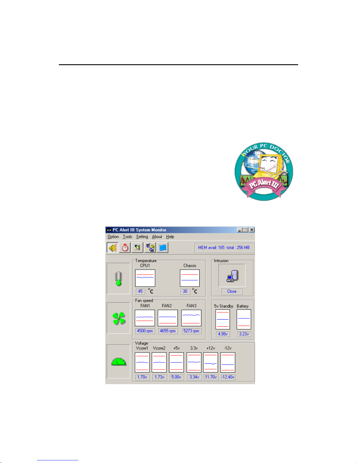
PC Alert™ III
The PC AlertTM III is an utility you can find in the CD-ROM disk. The
utility is just like your PC doctor that can detect the following PC hardware
status during real time operation:
* monitor CPU & system temperatures
* monitor fan speed(s)
* monitor system voltage
* monitor chassis intrusion
If one of the items above is abnormal, the program main
screen will be immediately shown on the screen, with the
abnormal item highlighted in red. This will continue to
be shown,until user disables the warning.
Page 15
1-8
Chapter 1
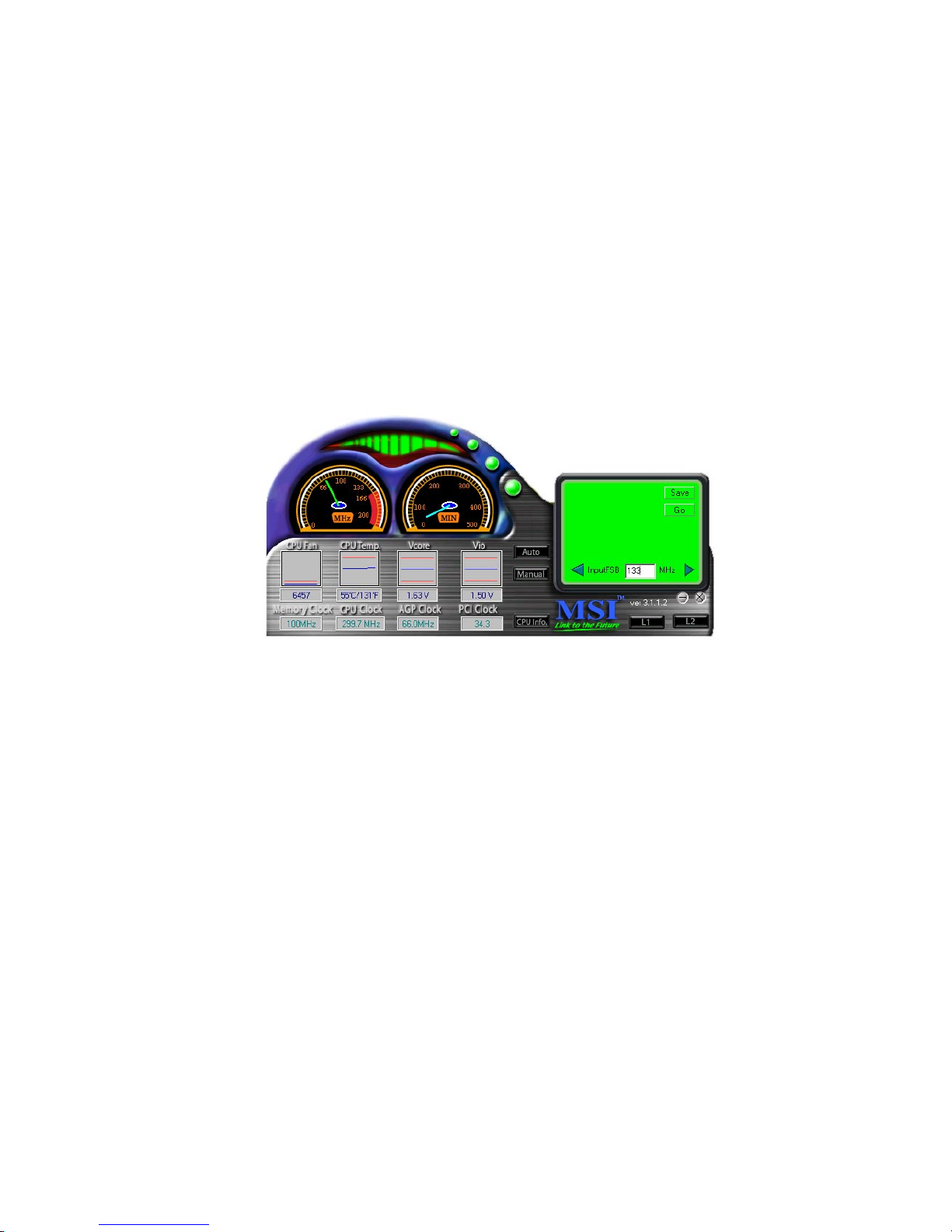
Fuzzy Logic™ III
The Fuzzy Logic™ III utility allows users to overclock the CPU FSB
(Front Side Bus) frequency in the Windows environment. Select the CPU frequency you prefer and click Go to apply the frequency or click Save allowing
the system to run at the specified frequency each time when the system is
powered on.
Features:
z Display Current System Status
- CPU Fan
- CPU T emp.
- Vcore
- Vio
- Memory Clock
- CPU Clock
- AGP Clock
- PCI Clock
z Adjust CPU FSB Frequency
Page 16
1-9
Getting Started
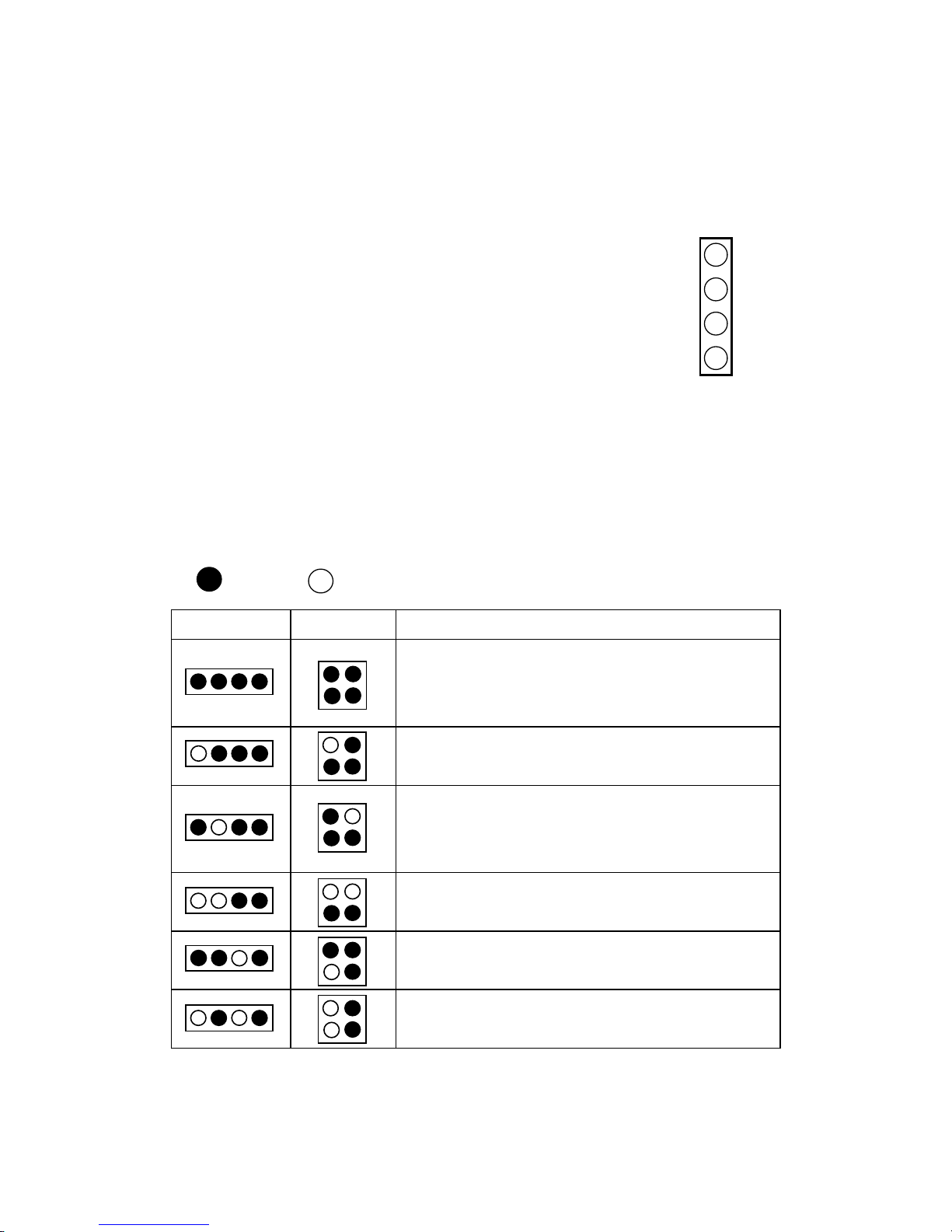
D-LED™ & D-Bracket™ (Optional)
The D-LED™ uses graphic signal display to help us-
ers understand their system. Four LEDs embedded in the
mainboard provide up to 16 combinations of signals to debug the system. The 4 LEDs can debug all problems that fail
the system, such as VGA, RAM or other failures. This special feature is very useful for the overclocking users. These
users can use the feature to detect if there are any problems
or failures.
1
2
3
4
Diagnostic LED
The D-Bracket™ , which is an external USB bracket integrating four Di-
agnostic LEDs, is optional. Definitions of the D-Bracket™ LED signals are the
same as D-LED™ as shown below.
Red
Green
D-LED D-Bracket Description
System Power ON
- The D-LED will hang here if the processor is damaged or
not installed properly.
Early Chipset Initialization
Memory Detection Test
- Testing onboard memory size. The D-LED will hang if
the memory module is damaged or not installed properly.
Decompressing BIOS image to RAM for fast booting.
Initializing Keyboard Controller.
Testing VGA BIOS
- This will start writing VGA sign-on message to the screen.
1 2 3 4
1 2
3 4
Page 17
1-10
Chapter 1
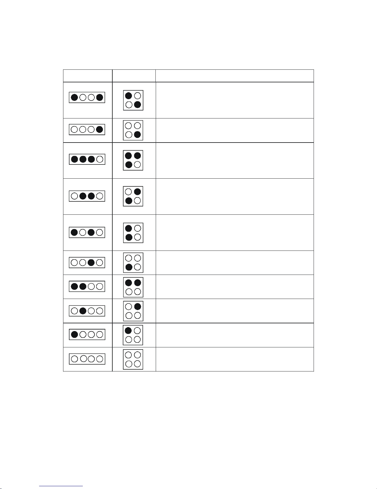
Descri pti on
D-LE D
D-Brac ke t
Processor Initialization
- It will show information of the processor ( brand
name, system bus and so on)
Testing RTC (Real Time Clock)
Initializing Video Interface
- It will detect CPU clock and check the onboard video
type, and then detect and initialize the video adapter.
BIOS Sign-On
- It will show information of the logo, brand name of
the processor and so on.
Testing Base and Extended Memory
- It will test base memory from 240K to 640K and
extended memory above 1MB using various patterns.
Assigning Resources to all ISA
Initializing Hard Drive Controller
- It will initialize IDE drive and controller.
Initializing Floppy Drive Controller
- It will initialize floppy drive and controller.
Boot Attempt
- It will set low stack and boot via INT 19h.
Booting Operating System
Page 18

2-1
Hardware Setup
Chapter 2. Hardware Setup
TOPICS
Central Processing Unit: CPU 2-2
Memory 2-7
Power Supply 2-10
Back Panel 2-12
Connectors 2-17
Jumpers 2-27
Slots 2-28
2
Hardware Setup
This chapter provides you with the information about hardware setup
procedures. While doing the installation, be careful in holding the components
and follow the installation procedures. For some components, if you install in
the wrong orientation, the components will not work properly.
Use a grounded wrist strap before handling computer components. Static
electricity may damage the components.
Page 19
2-2
Chapter 2
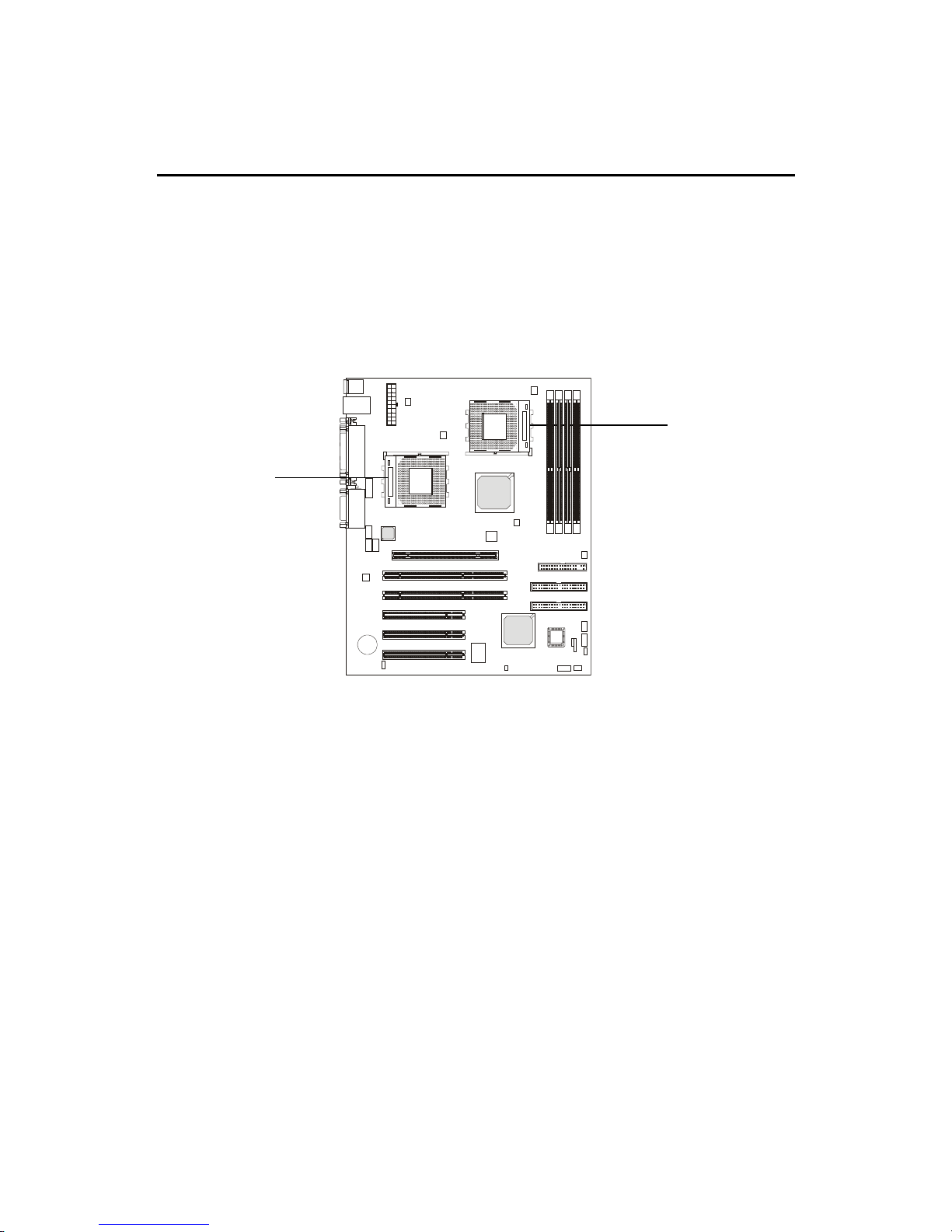
Central Processing Unit: CPU
The MSI mainboard supports Single/Dual AMD® AthlonTM MP
processor(s). The mainboard uses two CPU sockets called Socket A for easy
CPU installation. You can install SINGLE or DUAL CPUs on the board to meet
your own needs. Keep the following points in mind before installing CPU(s):
1. If SINGLE CPU is intended, always install the CPU on the CPU1
socket.
2. T o install DUAL CPUs on the board, you must use the same types
of CPUs running at the same FSB frequency.
When you are installing the CPU, make sure the CPU has a Heat Sink
and a cooling fan attached on the top to prevent overheating. If you do not find
the Heat Sink and cooling fan, contact your dealer to purchase and install them
before turning on the computer.
CPU1
CPU2
Page 20
2-3
Hardware Setup
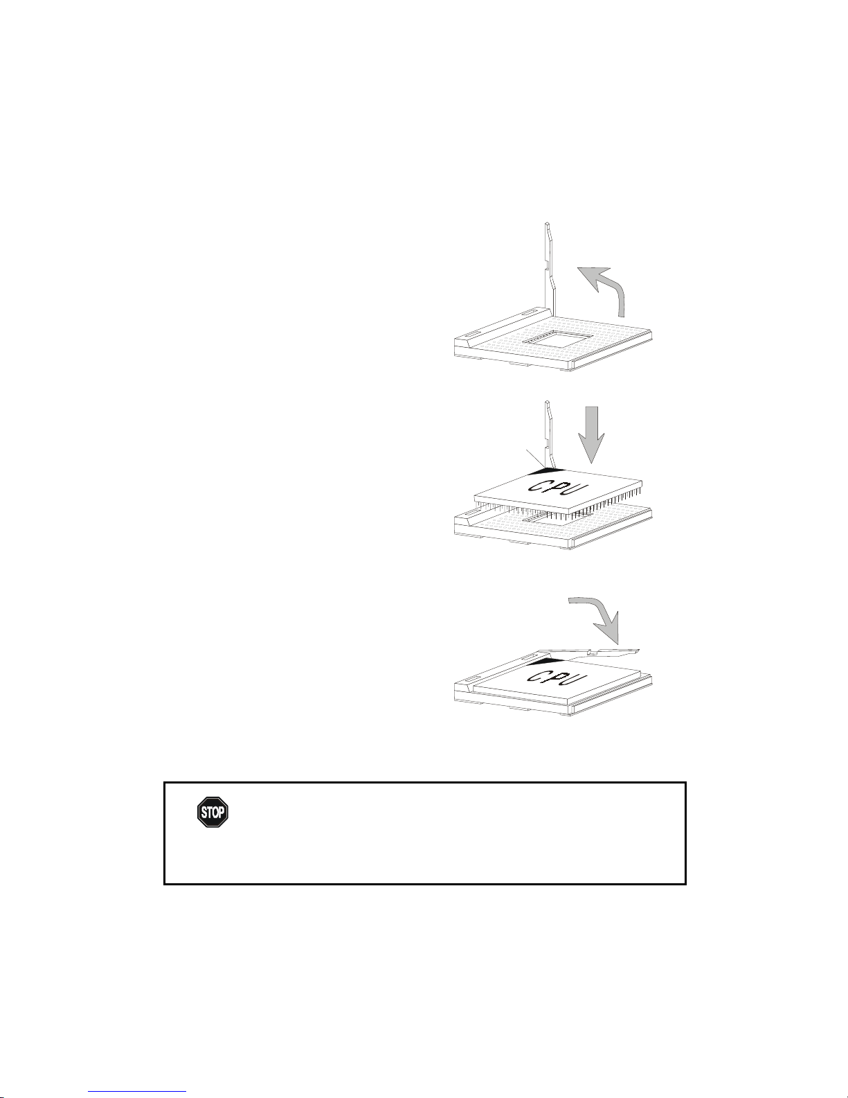
1 . Pull the lever sideways away
from the socket. Then, raise
the lever up to a 90-degree
angle.
2. Look for the cut edge. The
cut edge should point
towards the lever pivot. The
CPU will only fit in the
correct orientation.
3. Hold the CPU down firmly,
and then close the lever to
complete the installation.
CPU Installation Procedures
Open Lever
Cut edge
Sliding
Plate
Close
Lever
Overheating will seriously damage the CPU and system,
always make sure the cooling fan can work properly to
protect the CPU from overheating.
W ARNING!
Page 21

2-4
Chapter 2
Thermal Issue for CPU
As processor technology pushes to faster speeds and higher
performance, thermal management becomes increasingly cru-
cial when building computer systems. Maintaining the proper
thermal environment is key to reliable operation. As such, the processor must
be maintained in the specified thermal requirements. AMD recommends the
use of high performance thermal interface material.
AMD Athlon™ processor with a speed of 600MHz and above requires LARGER
heatsink and fan. You also need to add thermal grease between the CPU and
heatsink to improve heat dissipation. Then, make sure that the CPU and heatsink
are securely fastened and in good contact with each other. These are needed
to prevent damaging the processor and ensuring reliable operation.
You can check AMD’s web site for more information on proper cooling.
WARNING!
Page 22
2-5
Hardware Setup
CPU Core Speed Derivation Procedure
If CPU Clock = 100MHz
Core/Bus ratio = 7
then CPU core speed = Host Clock x Core/Bus ratio
= 100MHz x 7
= 700MHz
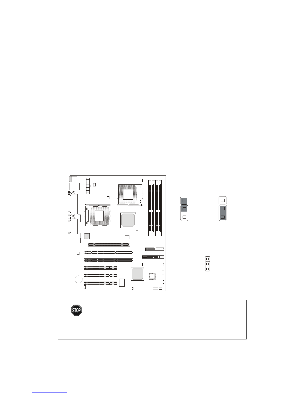
While replacing the CPU, always turn off the ATX
power supply or unplug the power cable of the ATX
power supply from grounded outlet first to ensure the
safety of CPU.
WARNING!
CPU Clock Frequency Selection: JFSB1
The default hardware configuration for CPU Clock Frequency is set at
100 MHz. T o use a 133 MHz CPU, you need to adjust the CPU clock up to 133
MHz by setting the JFSB1 jumper.
1
133 MHz
3
100MHz
3
1
JFSB1
1
Page 23
2-6
Chapter 2
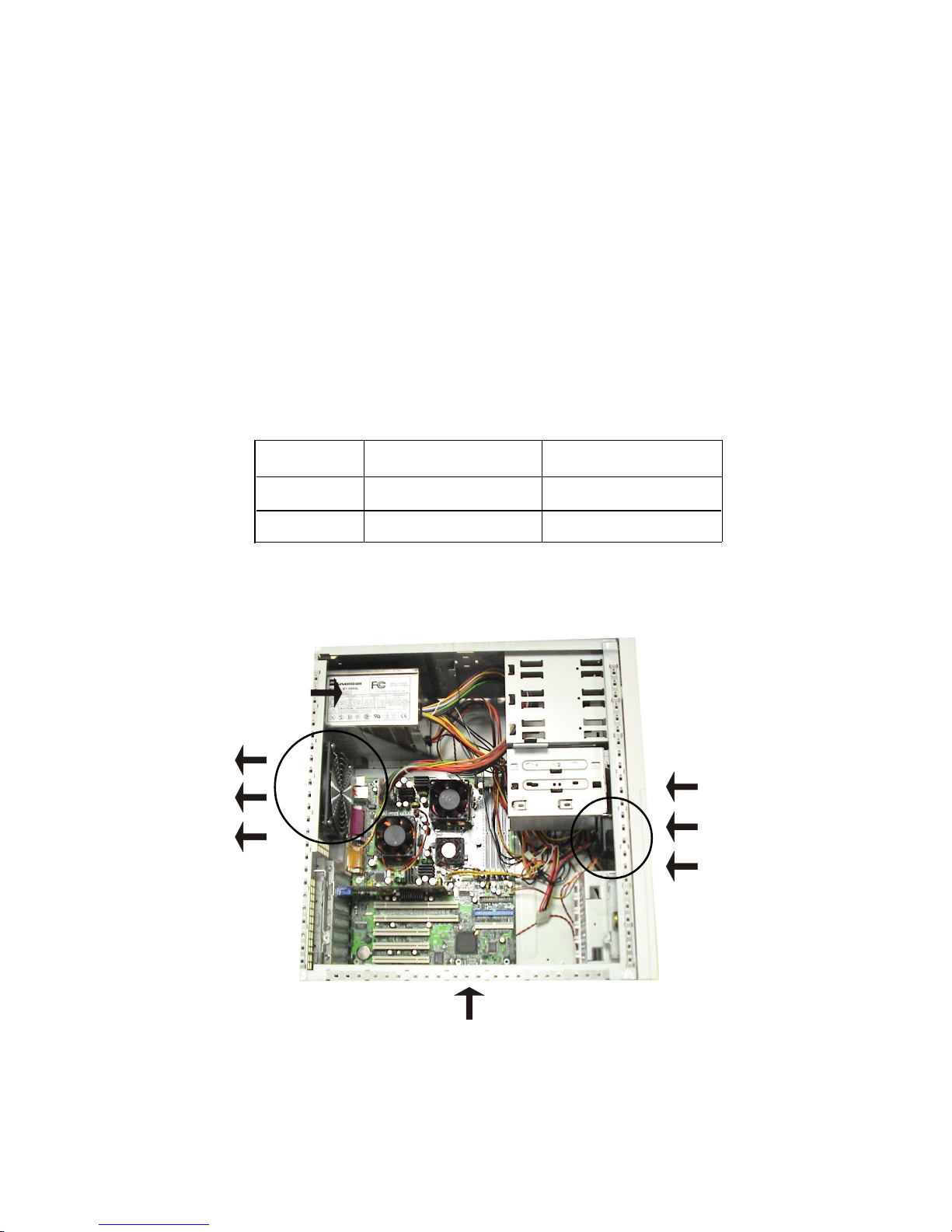
Recommended Computer Case and Axial Fans
To accommodate the MS-6501 mainboard, Axial Fans and other re-
quired components, we recommend that you use the ATX computer case.
To maintain a well-ventilated operating environment and prevent CPU
overheating problems, we strongly suggest that you add two axial fans to the
system. The specification of the Front/Rear Axial Fans are as follows:
Front Axial Fan
(air flows in)
Rear Axial Fan
(heat flows out)
MS-6501
ATX Power Supply
ATX Computer Case
Axial Fan Length x Width Running Speed
Front 80mm x 25mm 12V at 2500 rpm
Rear 120mm x 25mm 12V at 2200 rpm
Page 24
2-7
Hardware Setup
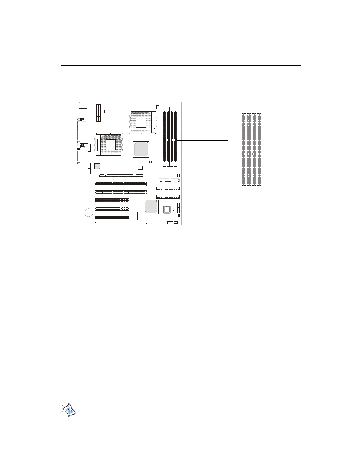
The mainboard provides 4 sockets for 184-pin, 2.5V DDR DIMM with 8
memory banks. T o operate properly , at least one DIMM module must be installed.
Memory Installation
Y ou can install PC1600/PC2100 DDR SDRAM modules on the DDR DIMM
slots (DDR 1~4).
DDR (Double Data Rate) SDRAM is similar to conventional SDRAM,
but doubles the rate by transfering data twice per cycle. It transfers data on
both the rising and falling edges of the clock. Conventional SDRAM only uses
the rising edge of the clock to transfer data. Therefore, conventional SDRAM
is called SDR (Single Data Rate) SDRAM.
DDR SDRAM uses 2.5 volts as opposed to 3.3 volts used in SDR
SDRAM, and requires 184-pin DIMM modules rather than 168-pin DIMM
modules used by SDR SDRAM. DDR SDRAM is also known as SDRAM-II,
DDR DRAM and DSDRAM (Double-Speed DRAM).
T wo types of DDR are available at the time of writing: PC1600 & PC2100.
PC1600 DDR SDRAM running at 100MHz will produce about 1.6GB/s memory
bandwidth. PC2100 running at 133MHz will produce 2.1GB/s memory bandwidth.
High memory bandwidth makes DDR an ideal solution for high performance
PC, workstations and servers.
Note: Registered DIMMs can be placed into DDR1~4 but unbuffered
DIMMs can be placed into DDR1~2 only .
DDR DIMM Slots
(DDR 1~4)
D
D
R
1
D
D
R
2
D
D
R
3
D
D
R
4
Page 25

2-8
Chapter 2
DDR Module Combination
T o enable normal operation, at least one DIMM module must be installed
on the mainboard. As the AMD-762TM chipset supports 4 DDR memory banks
at its maximum, the system memory installed can be up to 4 GB.
You can install memory modules in the following combination:
Devices used on DIMM
64 MB (4Mx4x4 banks)
64 MB (2Mx8x4 banks)
64 MB (1Mx16x4 banks)
128 MB (8Mx4x4 banks)
128 MB (4Mx8x4 banks)
128 MB (2Mx16x4 banks)
256 MB (16Mx4x4 banks)
256 MB (8Mx8x4 banks)
256 MB (4Mx16x4 banks)
512 MB (32Mx4x4 banks)
512 MB (16Mx8x4 banks)
512 MB (8Mx16x4 banks)
Note: The maximum address space supported by the AMD-762 system controller is four Gbytes.
1 DIMM
(2 Rows)
x64/x72
256 MB
128 MB
64 MB
512 MB
256 MB
128 MB
1 GB
512 MB
256 MB
2 GB
1 GB
512 MB
2 DIMMs
(2 Rows each)
x64/x72
512 MB
256 MB
128 MB
1 GB
512 MB
256 MB
2 GB
1 GB
512 MB
4 GB
2 GB
1 GB
3 DIMMs
(2 Rows each)
x64/x72
768 MB
384 MB
192 MB
1.5 GB
768 MB
384 MB
3 GB
1.5 GB
768 MB
4 GB
3 GB
1.5 GB
4 DIMMs
(2 Rows each)
x64/x72
1 GB
512 MB
256 MB
2 GB
1 GB
512 MB
4 GB
2 GB
1 GB
4 GB
4 GB
2 GB
Page 26
2-9
Hardware Setup
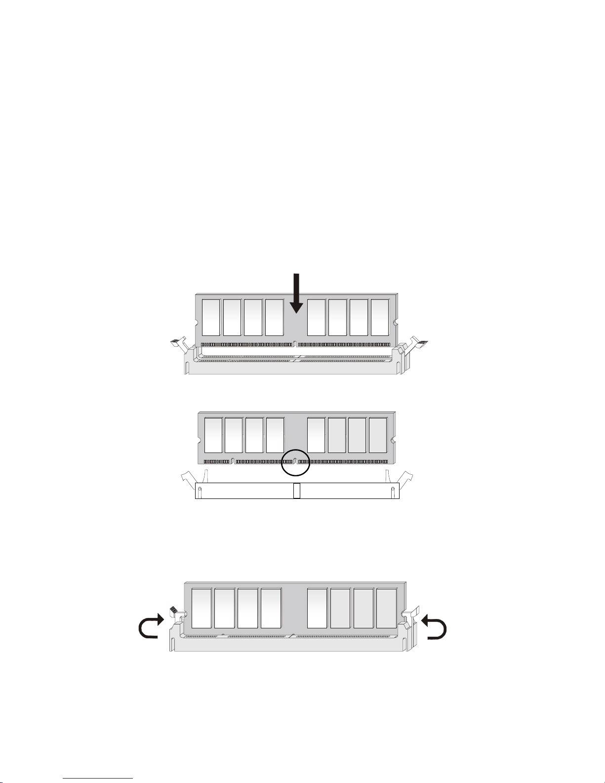
DDR Module Installation Procedures
You can install either single-sided or double-sided 184-pin DDR DIMM
modules into DDR DIMM slots to meet your needs. Different from the SDR
DIMM, the DDR DIMM has only one notch on the center of module. The
number of pins on either side of the breaks are different. The module will only
fit in the right orientation.
2. The plastic clips at sides of the DIMM slot will automatically close.
1. Insert the DIMM module vertically into the DDR DIMM slot. Make sure the
notch is on the right orientation.
Volt
Page 27
2-10
Chapter 2
Power Supply
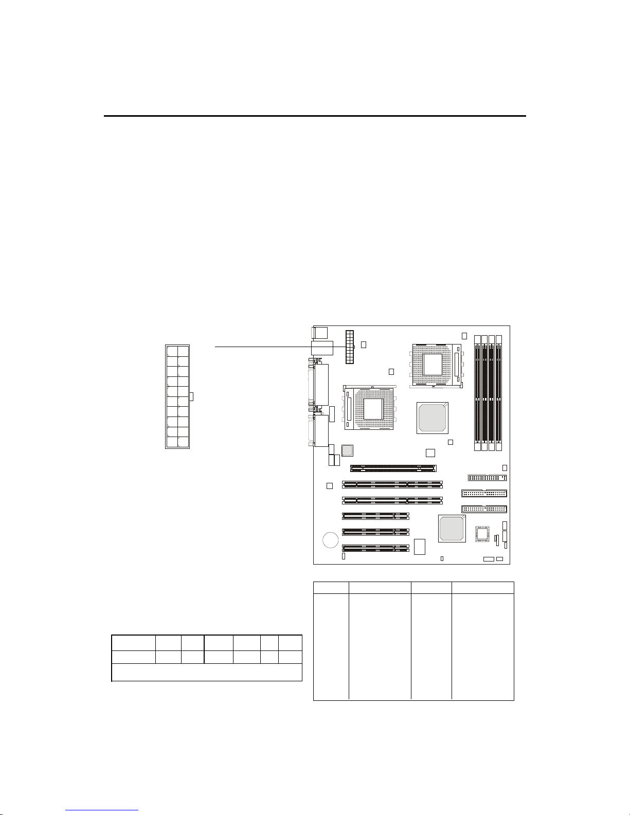
A TX 20-Pin Power Connector: JPWR1
This connector allows you to connect to an ATX power supply. To
connect to the ATX power supply , make sure the plugs of the power supply is
inserted in the proper orientation and the pins are aligned. Then push down
the power supply firmly into the connector. The power connector supports
instant power on function which means that system will boot up immediately
when the power supply connector is inserted on the board.
The mainboard supports ATX power supply for the power system. Be-
fore inserting the power supply connector, always make sure that all components are installed properly to ensure that no damage will be caused.
PIN SIGNAL
11 3.3V
12 -12V
13 GND
14 PS_ON
15 GND
16 GND
17 GND
1 8 -5V
19 5V
20 5V
PIN SIGNAL
1 3.3V
2 3.3V
3 GND
45V
5 GND
65V
7 GND
8 PW_OK
9 5V_SB
10 12V
Recommended Power Supply Requirement
DC Output +12V +5V +3.3V 5VSB -5V -12V
MIN (A) 12A 35A 16A 2A 0 0.5A
Minimum Power 300W
JPWR1
10
1
20
11
Page 28
2-11
Hardware Setup
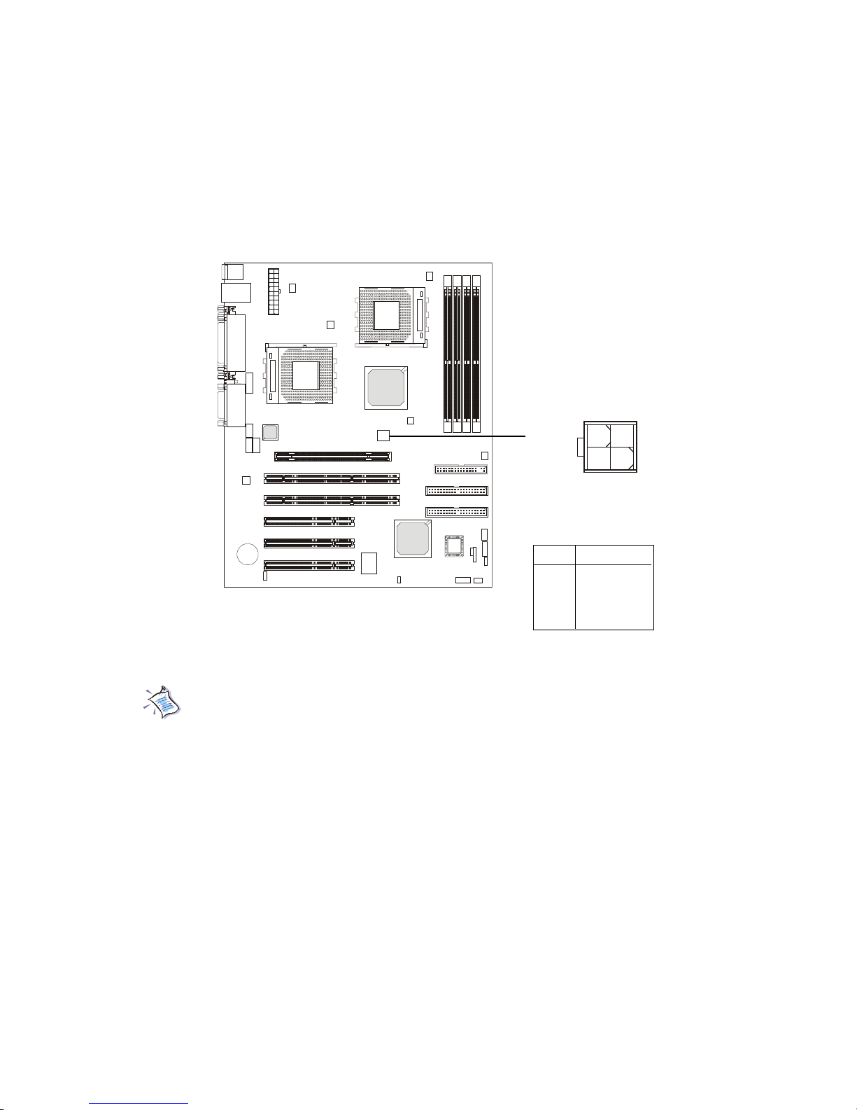
A TX 12V Power Connector: J4
This 12V power connector is used to provide power for the CPU & the
AGP Pro card.
Note: Always make sure to connect a power cable to the J4 to provide
power for the CPU & the AGP Pro card. Even if you do not intend to use
AGP Pro card, you still have to connect the J4 in order to ensure that
CPU will work properly with sufficient power input.
J4
1
3
24
PIN SIGNAL
1 GND
2 GND
312V
412V
Pin Definition
Page 29
2-12
Chapter 2
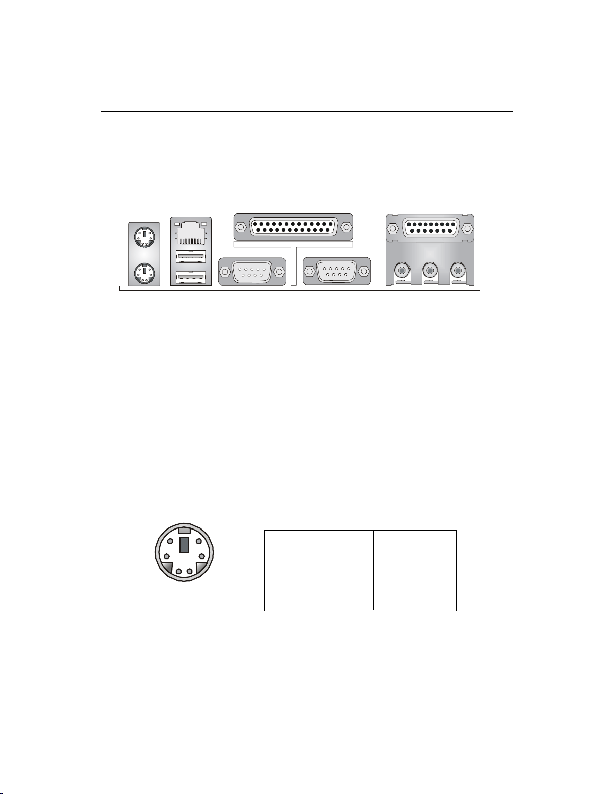
The Back Panel provides the following connectors:
Mouse Connector: KBMS1
The mainboard provides a standard PS/2® mouse mini DIN connector for
attaching a PS/2® mouse. You can plug a PS/2® mouse directly into this
connector. The connector location and pin assignments are as follows:
Back Panel
PS/2 Mouse (6-pin Female)
PIN SIGNAL DESCRIPTION
1 Mouse DAT A Mouse DA T A
2 NC No connection
3 GND Ground
4 VCC +5V
5 Mouse Clock Mouse clock
6 NC No connection
Pin Definition
COM A
COM B
Parallel Port
Joystick/MIDI
Line Out Line In Mic
PS/2 Keyboard
PS/2 Mouse
USB Ports 1 & 2
RJ-45 LAN Port
2
1
3
4
56
Page 30
2-13
Hardware Setup
Keyboard Connector: KBMS1
The mainboard provides a standard PS/2® keyboard mini DIN connector
for attaching a PS/2® keyboard. You can plug a PS/2® keyboard directly into
this connector.
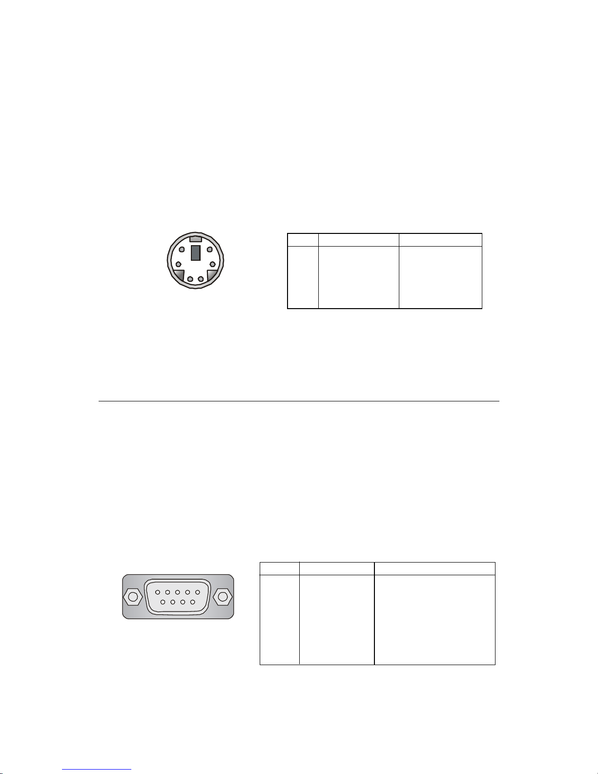
Serial Port Connectors: COM A & COM B
The mainboard offers two 9-pin male DIN connectors as serial ports
COM A and COM B. The ports are 16550A high speed communication ports
that send/receive 16 bytes FIFOs. You can attach a serial mouse or other serial
devices directly to them.
PS/2 Keyboard (6-pin Female)
PIN SIGNAL DESCRIPTION
1 Keyboard DAT A Keyboard DAT A
2 NC No connection
3 GND Ground
4 VCC +5V
5 Keyboard Clock Keyboard clock
6 NC No connection
Pin Definition
2
1
3
4
56
PIN SIGNAL DESCRIPTION
1 DCD Data Carry Detect
2 SIN Serial In or Receive Data
3 SOUT Serial Out or Transmit Data
4 DTR Data Terminal Ready)
5 GND Ground
6 DSR Data Set Ready
7 RTS Request T o Send
8 CTS Clear T o Send
9 RI Ring Indicate
9-Pin Male DIN Connector
Pin Definition
1 2 3 4 5
6 7 8 9
Page 31

2-14
Chapter 2
The mainboard provides an optional RJ-45 LAN connector for your
network connection.
LAN Connector (optional)
RJ-45 LAN Jack
USB Connectors
The mainboard provides a UHCI (Universal Host Controller Interface)
Universal Serial Bus root for attaching USB devices such as keyboard, mouse
or other USB-compatible devices. You can plug the USB device directly into
ths connector.
PIN SIGNAL DESCRIPTION
1 VCC +5V
2 -Data 0 Negative Data Channel 0
3 +Data0 Positive Data Channel 0
4 GND Ground
5 VCC +5V
6 -Data 1 Negative Data Channel 1
7 +Data 1 Positive Data Channel 1
8 GND Ground
USB Port Description
USB Ports
1 2 3 4
5 6 7 8
PIN SIGNAL DESCRIPTION
1 TDP Transmit Differential Pair
2 TDN Transmit Differential Pair
3 RDP Receive Differential Pair
4 NC Not Used
5 NC Not Used
6 RDN Receive Differential Pair
7 NC Not Used
8 NC Not Used
LAN Jack Pin Definition
Page 32

2-15
Hardware Setup
Parallel Port Connector: LPT1
The mainboard provides a 25-pin female centronic connector as LPT. A
parallel port is a standard printer port that supports Enhanced Parallel Port
(EPP) and Extended Capabilities Parallel Port (ECP) mode.
PIN SIGNAL DESCRIPTION
1 STROBE Strobe
2 DATA0 Data0
3 DATA1 Data1
4 DATA2 Data2
5 DATA3 Data3
6 DATA4 Data4
7 DATA5 Data5
8 DATA6 Data6
9 DATA7 Data7
10 ACK# Acknowledge
11 BUSY Busy
12 PE Paper End
1 3 SELECT Select
1 4 AUTO FEED# Automatic Feed
15 ERR# Error
1 6 INIT# Initialize Printer
17 SLIN# Select In
18 GND Ground
19 GND Ground
20 GND Ground
21 GND Ground
22 GND Ground
23 GND Ground
24 GND Ground
25 GND Ground
Pin Definition
13 1
14
25
Page 33

2-16
Chapter 2
Joystick/Midi Connectors
You can connect a joystick or game pad to this connector.
Audio Port Connectors
Line Out is a connector for Speakers or Headphones. Line In is used for
external CD player, Tape player, or other audio devices. Mic is a connector for
microphones.
Note: If you choose to enable the Audio Multi-Channel, this will change the
Line In to 3, 4 channel output and MIC to 5, 6 channel output (optional). To use
this function, set the Audio Multi-Channel to enable located at the BIOS Inte-
grated Peripherals or install the driver provided with this mainboard.
1/8” Stereo Audio Connectors
Line Out Line In M IC
Page 34

2-17
Hardware Setup
The mainboard provides connectors to connect to FDD, IDE HDD, case,
modem, LAN, USB Ports, IR module and CPU/System F AN.
Floppy Disk Drive Connector: FDD1
The mainboard provides a standard floppy disk drive connector that
supports 360K, 720K, 1.2M, 1.44M and 2.88M floppy disk types.
Connectors
FDD1
Page 35

2-18
Chapter 2
Hard Disk Connectors: IDE1 & IDE2
The mainboard has a 32-bit Enhanced PCI IDE and Ultra DMA 33/66/100
controller that provides PIO mode 0-4, Bus Master, and Ultra DMA 33/66/100
functions. It has two HDD connectors IDE1 (Primary) and IDE2 (Secondary).
You can connect up to four hard disk drives, CD-ROM or 120MB Floppy to
IDE1 and IDE2.
IDE1 (Primary IDE Connector)
- The first hard disk drive should always be connected to IDE1. You can
connect a Master and a Slave drive to IDE1.
IDE2 (Secondary IDE Connector)
- You can connect a Master and a Slave drive to IDE2.
IDE 1
IDE 2
TIP:
If you install two hard disks on cable, you must configure the
second drive to Slave mode by setting its jumper. Refer to the
hard disk documentation supplied by hard disk vendors for jumper
setting instructions.
Page 36

2-19
Hardware Setup
Front Panel Connector: JFP1 & JFP2
The front panel connectors JFP1 and JFP2 allow you to connect to the
Power Switch, Reset Swtich, Speaker, Power LED, and HDD LED on the case.
Both JFP1 and JFP2 are compliant with Intel® Front Panel I/O Connectivity
Design Guide.
Pin Signal
1 GND
2 SPK3 SLED
4 BUZ+
Pin Signal
5 PLED
6 BUZ7NC
8 SPK+
JFP2 Pin Definition
PIN SIGNAL DESCRIPTION
1 HD_LED_P Hard disk LED pull-up to +5V
2 FP PWR/SLP MSG LED pull-up to +5V
3 HD_LED_N Hard disk active LED
4 FP PWR/SLP MSG LED pull-up to +5V
5 RST_SW_N Reset Switch low reference pull-down to GND
6 PWR_SW_P Power Switch high reference pull-up to +5V
7 RST_SW_P Reset Switch high reference pull-up to +5V
8 PWR_SW_N Power Switch low reference pull-down to GND
9 RSVD_DNU Reserved. Do not use.
JFP1 Switch/LED Front Panel Electrical Connection
JFP1
10
192
HDD
S
PWSW
RST
-
LED
P
+
+
-
-
+
1
2
JFP2
7
8
P
GND
+
+
-
-
LED
SPK
S
BUZ
Page 37

2-20
Chapter 2
CD-In Connector: JCD1
The connector is for CD-ROM audio connector.
Aux Line-In Connector: JAUX1
The connector is for DVD add-on card with Line-in connector .
Modem-In Connector: JPHN1
The connector is for modem with internal audio connector.
JCD1
JAUX1
GND
R
L
JPHN1
GND
Phone_In
Mono_Out
GND
R
L
Page 38

2-21
Hardware Setup
W ake On LAN Connector: JWL1
This connector allows you to connect to a LAN card with Wake On
LAN function. You can wake up the computer via remote control through a
local area network. JWL1 is compliant with Intel® Front Panel I/O Connectivity
Design Guide.
W ake On Ring Connector: JWR1
This connector allows you to connect to a modem card with Wake On
Ring function. The connector will power up the system when a signal is
received through the modem card. JWR1 is compliant with Intel® Front Panel
I/O Connectivity Design Guide.
JWR1
NC
WOR (wake-up on ring)
NC
5VSB
1
GND
JWL1
5VSB
GND
WOL
(wake-up on LAN)
1
Page 39

2-22
Chapter 2
Fan Power Connectors: CPUFAN1/CPUFAN2/PSFAN1/
SYSFAN/NBF AN1
The CPUFAN1 & 2 (processor fans), PSFAN1 (power supply fan),
SYSF AN (system fan), and NBF AN1 (NorthBridge fan) support system cooling
fan with +12V. It supports two/three-pin head connector. When connecting
the wire to the connectors, always take note that the red wire is the positive
and should be connected to the +12V, the black wire is Ground and should be
connected to GND. If the mainboard has a System Hardware Monitor chipset
on-board, you must use a specially designed fan with speed sensor to take
advantage of the CPU fan control.
Note:
1. Always consult the vendor for proper CPU cooling fan.
2. CPU Fan supports the fan control. You can install the PC Alert
utility that will automatically control the CPU Fan speed according
to the actual CPU temeperature.
NBF AN1
GND+12V
SENSOR
+12V
GND
SYSFAN
SENSOR
+12V
GND
CPUFAN1
SENSOR
+12V
GND
CPUF AN2
SENSOR
+12V
GND
PSF AN1
Page 40

2-23
Hardware Setup
USB Front Panel Connector: JUSB1
The mainboard provides a Universal Serial Bus (USB) pin header that
allows you to connect an optional USB port for front panel. JUSB1 is compliant with Intel® Front Panel I/O Connectivity Design Guide.
Pin Description Pin Description
1 USBPWR 6 USBP1+
2 USBPWR 7 GND
3 USBP0- 8 GND
4 USBP1- 9 NC
5 USBP0+ 10 USBOC-
JUSB1 Pin Definition
JUSB1
1
9
2
10
Page 41

2-24
Chapter 2
D-Bracket™ Connector: JDB1
The mainboard comes with a JDB1 connector for you to connect to DBracket™. D-Bracket™ is a USB Bracket integrating four LEDs whose functions are similar to D-LED™ and allows users to identify system problem through
16 various combinations of LED signals. For definitions of 16 signal
combinations, please refer to Chapter 1. D-LED™ & D-Bracket™.
Pin Description Pin Description
1 DBG1 6 DBR3
2 DBR1 7 DBG4
3 DBG2 8 DBR4
4 DBR2 9 Key
5 DBG3 10 NC
JDB1 Pin Definition
D-Bracket™
Connected to JDB1
Connected to JUSB1
1
9
2
10
JDB1
Page 42

2-25
Hardware Setup
IrDA Infrared Module Connector: JIR1
This connector allows you to connect an IrDA Infrared module. You
must configure the setting through the BIOS setup to use the IR function. JIR1
is compliant with Intel® Front Panel I/O Connectivity Design Guide.
JIR1
1
256
Pin Definition
Pin Signal Description Pin Signal Description
1 NC Not Assigned 2 (No pin) Key
3 +5V IR Power 4 GND Ground
5 IRTX IrDA serial output 6 IRRX IrDA serial input
Page 43

2-26
Chapter 2
Chassis Intrusion Switch Connector: JCI1
This connector is connected to a 2-pin chassis switch. If the chassis is
opened, the switch will be short. The system will record this status and show
a warning message on the screen. To clear the warning, you must enter the
BIOS utility and clear the record. JCI1 is compliant with Intel® Front Panel I/O
Connectivity Design Guide.
JCI1
1
CINTRU
GND
2
Page 44

2-27
Hardware Setup
Clear CMOS Jumper: JBA T1
There is a CMOS RAM on board that has a power supply from external
battery to keep the data of system configuration. With the CMOS RAM, the
system can automatically boot OS every time it is turned on. That battery has
long life time for at least 5 years. If you want to clear the system configuration,
turn off the AC power first and then use the JBAT1 (Clear CMOS Jumper ) to
clear data. JBAT1 is compliant with Intel® Front Panel I/O Connectivity Design
Guide. Follow the instructions below to clear the data:
Jumpers
The motherboard provides one jumper for you to set the computer’s
function. This section will explain how to change your motherboard’ s function
through the use of the jumper.
You can clear CMOS by shorting 2-3 pin while the
system is off. Then return to 1-2 pin position. Avoid
clearing the CMOS while the system is on; it will
damage the mainboard.
WARNING!
1
Clear Data
3
Keep Data
3
1
JBAT1
1
GND
RTCRST#
VBAT
Page 45

2-28
Chapter 2
AGP (Accelerated Graphics Port) Pro Slot
The AGP Pro slot allows you to insert the AGP or AGP Pro graphics cards. The
universal AGP Pro slot is an extension of the existing AGP slot (with two
extended sections on both ends of the original AGP slot) and is backward
compatible with existing AGP cards.
PCI Slots
This mainboard offers two types of PCI slots for you to insert the desired
expansion cards:
1. PCI 64bit/66MHz---supports 3V or universal cards (can be downgraded to
PCI 32bit/33MHz or PCI 64bit/33MHz)
2. PCI 32bit/33MHz---supports 5V or universal cards
When adding or removing expansion cards, make sure that you unplug the
power supply first. Meanwhile, read the documentation for the expansion card
to make any necessary hardware or software settings for the expansion card,
such as jumpers, switches or BIOS configuration.
Slots
The motherboard provides one AGP Pro slot, three 32-bit master PCI bus
slots, and two 64-bit master PCI bus slots.
64-Bit PCI Slots
AGP Pro Slot
32-Bit PCI Slots
Page 46

2-29
Hardware Setup
PCI Interrupt Request Routing
The IRQ, abbreviation of interrupt request line and pronounced I-R-Q,
are hardware lines over which devices can send interrupt signals to the
microprocessor. The PCI IRQ pins are typically connected to the PCI bus INT
A# ~ INT D# pins as follows:
Order 1 Order 2 Order 3 Order 4
PCI Slot 1 INT A# INT B# INT C# INT D#
PCI Slot 2 INT B# INT C# INT D# INT A#
PCI Slot 3 INT A# INT B# INT C# INT D#
PCI Slot 4 INT B# INT C# INT D# INT A#
PCI Slot 5 INT C# INT D# INT A# INT B#
Page 47

AWARD® BIOS Setup
3-1
Chapter 3.
AWARD® BIOS
Setup
If your motherboard comes with the AWARD® BIOS ROM, read this
chapter for an overview of the Award® BIOS settings. AWARD® BIOS ROM
provides a Setup utility for users to modify the basic system configuration.
The information is stored in a battery-backed CMOS RAM so it retains the
Setup information when the power is turned off.
TOPICS
Entering Setup 3 -2
The Main Menu 3-4
Standard CMOS Features 3-6
Advanced BIOS Features 3 -8
Advanced Chipset Features 3-11
Integrated Peripherals 3-14
Power Management Setup 3-19
PnP/PCI Configurations 3-23
PC Health Status 3-25
Frequency/Voltage Control 3-26
Load Fail-Safe/Optimized Defaults 3-27
Set Supervisor/User Password 3-28
Chapter 3. BIOS Setup
3
AWARD® BIOS Setup
Page 48

Chapter 3
3-2
Entering Setup
Control Keys
Power on the computer and the system will start POST (Power On Self
Test) process. When the message below appears on the screen, press <DEL>
to enter Setup.
Press <DEL> to Enter SETUP
If the message disappears before you respond and you still wish to enter
Setup, restart the system by turning it OFF then On or pressing the RESET
button to try again. You may also restart by simultaneously pressing <Ctrl>,
<Alt>, and <Delete> keys.
Move to the previous item
Move to the next item
Move to the item on the left-hand side
Move to the item on the right-hand side
Select the item
Jumps to the Exit menu or returns to the main menu from a
submenu
<Enter>
<Esc>
General help, only for Status Page Setup Menu and Option
Page Setup Menu
Decrease the numeric value or make changes
Increase the numeric value or make changes
<+/PU>
<-/PD>
<F1>
<F5>
Restore the previous CMOS value from CMOS, only for Option
Page Setup Menu
Load the default CMOS value from Fail-Safe default table, only
for Option Page Setup Menu
<F10>
<F7>
<F6>
Load Optimized defaults
Save all the CMOS changes and exit
< >
< >
< >
< >
Page 49

AWARD® BIOS Setup
3-3
Getting Help
Sub-Menu
If you find a right pointer symbol (as shown in
the right view) appears to the left of certain fields
that means a sub-menu can be launched from
this field. A sub-menu contains additional options for a field parameter. You can use control
keys ( ↑↓ ) to highlight the field and press <Enter>
to call up the sub-menu. Then you can use the
control keys to enter values and move from field
to field within a sub-menu. If you want to return
to the main menu, just press the <Esc >.
General Help <F1>
The BIOS setup program provides a General Help screen. You can call up this
screen from any menu by simply pressing <F1>. The Help screen lists the
appropriate keys to use and the possible selections for the highlighted item.
Press <Esc> to exit the Help screen.
After entering the Setup menu, the first menu you will see is the Main Menu.
Main Menu
The main menu lists the setup functions you can make changes to. You can use
the control keys ( ↑↓ ) to select the item. The on-line description of the highlighted setup function is displayed at the bottom of the screen.
8IDE Primary Master
8IDE Primary Slave
8IDE Secondary Master
8IDE Secondary Slave
Page 50

Chapter 3
3-4
The Main Menu
Standard CMOS Features
Use this Menu for basic system configurations.
Advanced BIOS Features
Use this menu to set the Advanced Features available on your system.
Advanced Chipset Features
Use this menu to change the values in the chipset registers and optimize your
system’ s performance.
Integrated Peripherals
Use this menu to specify your settings for integrated peripherals.
Power Management Setup
Use this menu to specify your settings for power management.
Once you enter A ward® BIOS CMOS Setup Utility , the Main Menu (Figure
1) will appear on the screen. The Main Menu allows you to select from twelve
setup functions and two exit choices. Use arrow keys to select among the
items and press <Enter> to accept or enter the sub-menu.
Page 51

AWARD® BIOS Setup
3-5
PnP/PCI Configurations
This entry appears if your system supports PnP/PCI.
PC Health Status
This entry shows your PC health status.
Frequency/V oltage Control
Use this menu to specify your settings for frequency/voltage control.
Load Fail-Safe Defaults
Use this menu to load the BIOS default values for the minimal/stable performance for your system to operate.
Load Optimized Defaults
Use this menu to load the BIOS default values that are factory settings for
optimal performance system operations.
Supervisor/User Password
Use this menu to set User and Supervisor Passwords.
Save & Exit Setup
Save CMOS value changes to CMOS and exit setup.
Exit Without Saving
Abandon all CMOS value changes and exit setup.
Page 52

Chapter 3
3-6
Standard CMOS Features
The items in Standard CMOS Features Menu are divided into 10
categories. Each category includes no, one or more than one setup items. Use
the arrow keys to highlight the item and then use the <PgUp> or <PgDn> keys
to select the value you want in each item.
Date
The date format is <day><month> <date> <year>.
day Day of the week, from Sun to Sat, determined by BIOS. Read-only.
month The month from Jan. through Dec.
date The date from 1 to 31 can be keyed by numeric function keys.
year The year, depends on the year of the BIOS
Time
The time format is <hour> <minute> <second>.
IDE Primary/Secondary Master/Slave
Press PgUp/<+> or PgDn/<-> to select Manual, None, Auto type. Note that the
specifications of your drive must match with the drive table. The hard disk will
not work properly if you enter improper information for this category. If your
hard disk drive type is not matched or listed, you can use Manual to define
your own drive type manually.
Page 53

AWARD® BIOS Setup
3-7
If you select Manual, related information is asked to be entered to the following items. Enter the information directly from the keyboard. This information
should be provided in the documentation from your hard disk vendor or the
system manufacturer.
If the controller of HDD interface is SCSI, the selection shall be “None”.
If the controller of HDD interface is CD-ROM, the selection shall be “None”.
Access Mode The settings are CHS, LBA, Large, Auto.
Capacity The formatted size of the storage device.
Cylinder Number of cylinders.
Head Number of heads.
Precomp Write precompensation.
Landing Zone Cylinder location of the landing zone.
Sector Number of sectors.
Drive A/B
This item allows you to set the type of floppy drives installed. Available
options are None, 360K, 5.25 in., 1.2M, 5.25 in., 720K, 3.5 in., 1.44M, 3.5 in.,
2.88M, 3.5 in..
Video
The setting controls the type of video adapter used for the primary monitor of
the system. Available options are EGA/VGA , CGA 40, CGA 80 and Mono.
Halt On
The setting determines whether the system will stop if an error is detected at
boot. Available options are:
All Errors The system stops when any error is detected.
No Errors The system doesn’t stop for any detected error.
All, But Keyboard The system doesn’t stop for a keyboard error.
All, But Diskette The system doesn’t stop for a disk error.
All, But Disk/Key The system doesn’t stop for either a disk or a
keyboard error.
Base/Extended/T otal Memory
The three items show the memory status of your system (read only).
Page 54

Chapter 3
3-8
Advanced BIOS Features
Virus Warning
Allows you to choose the VIRUS Warning feature for IDE Hard Disk boot
sector protection. If this function is enabled and someone attempts to write
data into this area, BIOS will show a warning message on screen and alarm
beep.
Disabled No warning message to appear when anything attempts
to access the boot sector or hard disk partition table.
Enabled Activates automatically when the system boots up
causing a warning message to appear when anything
attempts to access the boot sector of hard disk partition
table.
CPU Internal /External Cache
Cache memory is additional memory that is much faster than conventional
DRAM (system memory). When the CPU requests data, the system
transfers the requested data from the main DRAM into cache memory, for
even faster access by the CPU. This setting enables/disables the internal
cache (also known as L1 or level 1 cache) and external cache (also known as
L2 or level 2 cache). Settings are: Enabled and Disabled.
Page 55

AWARD® BIOS Setup
3-9
Quick Power On Self Test
This option allows the system to skip certain tests while booting. This will
decrease the time needed to boot the system.
Enabled Enable quick POST
Disabled Normal POST
First/Second/Third Boot Device
The BIOS attempts to load the operating system from the devices in the sequence selected in these items. The settings are Floppy, LS120, HDD-0/HDD-
1/HDD-2/HDD-3, SCSI, CDROM, LAN, ZIP100, and Disabled.
Boot Other Device
This option allows you to enable/disable the booting of other additional device.
Settings are: Enabled and Disabled.
Swap Floppy Drive
If the system has two floppy drives, choose Enabled to assign physical drive
B to logical drive A and vice-versa.
Boot Up Floppy Seek
When this item is enabled during POST, BIOS will determine if the floppy disk
drive installed is 40 or 80 tracks. 360K type is 40 tracks while 760K, 1.2M and 1.
44M are all 80 tracks. Settings are: Enabled and Disabled.
Floppy Disk Access Control
You can select R/W to read and add data to the floppy disk or Read Only to read
data from the floppy disk.
Boot Up NumLock Status
This option allows you to select the power on state for NumLock.
On Keypad is numeric keys.
Off Keypad is arrow keys.
Gate A20 Option
This item is to set the Gate A20 status. A20 refers to the first 64KB of extended
memory. When the default value Fast is selected, the Gate A20 is controlled
by Port 92 or chipset specific method resulting in faster system performance.
When Normal is selected, A20 is controlled by a keyboard controller or chipset
hardware.
Page 56

Chapter 3
3-10
T ypematic Rate Setting
Key strokes repeat at a rate determined by the keyboard controller. When
enabled, the typematic rate and typematic delay can be selected.
The settings are: Enabled/Disabled.
T ypematic Rate (Chars/Sec)
Sets the number of times a second to repeat a key stroke when you hold the key
down. The settings are: 6, 8, 10, 12, 15, 20, 24, 30.
T ypematic Delay (Msec)
Sets the delay time after the key is held down before it begins to repeat the
keystroke The settings are: 250, 500, 750, 1000.
Security Option
This option allows you to select whether the password is required every time
the system boots or only when you enter setup.
System The system will not boot and access to Setup will be
denied if the correct password is not entered at the prompt
Setup The system will boot, but access to Setup will be denied
if the correct password is not entered at the prompt.
MPS V ersion Contr ol For OS
This option allows you to control the MPS version for OS. Settings are: 1.1 or
1.4.
OS Select For DRAM > 64MB
This allows you to run the OS/2® operating system with DRAM greater than
64MB. Setting options are Non-OS2 and OS2.
Video BIOS Shadow
Shadowing is a technique used to increase a computer’s speed by using highspeed RAM memory in place of slower ROM memory. This setting enables/
disables the video BIOS to shadow into memory area C0000-C7FFF. Setting
options: Disabled and Enabled.
Small Logo(EP A) Show
This item allows you to show the company logo on the bootup screen. Settings
are: Disabled (shows the POST messages at boot) and Enabled (shows a still
logo on the full screen at boot).
Page 57

AWARD® BIOS Setup
3-11
The Advanced Chipset Features Setup option is used to change the
values of the chipset registers. These registers control most of the system
options in the computer.
Choose the “ADVANCED CHIPSET FEATURES” from the Main Menu
and the following screen will appear.
Advanced Chipset Features
System BIOS Cacheable
System BIOS ROM at F000h-F0000h is always copied to RAM for faster
execution. Selecting Enabled allows the contents of F0000h RAM memory
segment to be written to and read from cache memory, resulting in better system performance. However, if any program writes to this memory area, a system
error may result. The settings are Enabled or Disabled.
Video RAM Cacheable
The field allows the caching of video memory, resulting in increased system
performance. The settings are Enabled or Disabled.
BIOS ID of MP Capabilities
This item is to have the Athlon XP or MP processor running in multiprocessor
mode. Please select [Enabled] if an MP processor is installed; select [Disable]
to allow dual Athlon XP processors running in MP mode. However, the
[Disable] option only works when an old Athlon XP processor is used. If a
Page 58

Chapter 3
3-12
newer XP processor is installed, then a warning message could still appear on
screen no matter how you enable or disable this option.
Note: Some old Athlon processors can work in MP mode, because AMD did
not disable the multi-processing capability in these processors. But AMD has
disabled this MP feature in Athlon XP processors since 0.13 manufacturing
process is applied. Therefore, this BIOS option is just a service to old AMD
users and should not be considered as a solution to have Ahtlon XP processors
working like Athlon MPs.
Memory Hole At 15M-16M
You can reserve this area of system memory for ISA adapter ROM. When this
area is reserved, it cannot be cached. The user information of peripherals that
need to use this area of system memory usually discusses their memory
requirements. The settings are: Enabled or Disabled.
AGP Aperture Size (MB)
This option allows you to select the size of the Accelerated Graphics Port
(AGP) aperture. Aperture is a portion of the PCI memory address range dedicated to graphics memory address space. Host cycles that hit the aperture
range are forwarded to the AGP without any translation. The settings are: 32,
64, 128 and 256.
AGP ISA Aliasing
When enabled, address bits [15:10] will not be used in decoding. When disabled,
[15:10] are used for decoding. The settings are: Enabled or Disabled.
AGP Fast Write
The item enables or disables the AGP Fast Write feature. The Fast Write technology allows CPU to write directly into the graphics controller without passing anything through system memory and improves 4X speed accordingly.
Select Enabled only when your card supports the feature.
AGP Data T ransfer Mode
This allows you to set the AGP Data Transfer Mode. The settings are: 1x/2x, or
4x.
AGP Always Compensate
When set to Enabled, dynamic compensation is performed by AGP on an
Page 59

AWARD® BIOS Setup
3-13
ongoing basis at regular intervals.
AGP Secondary Lat Timer
This allows you to set the AGP Secondary Lat Timer. The settings are: 00h,
20h, 40h, 60h, 80h, C0h, FFh.
SDRAM ECC Setting
This allows you to set the SDRAM Error Correcting Code. The settings are:
Disabled, Check Only, Correct Errors, or Correct+Scrub.
Super Bypass Mode
When enabled, the chipset internally bypasses certain memory to CPU pipe
stages for optimal performance. The settings are: Disabled or Enabled.
Note: This item is hidden if both processors are running.
DDR SDRAM Timing Setting By
This feature allows you to set the DDR SDRAM Timing Setting. The options
are: Auto and Manual . When setting to Auto, the system will automatically set
proper values to DDR SDRAM Idle Limit, Page Hit Limit, Trc Cycle, Trp Cycle,
Tras Cycle, CAS Latency Cycle and T rcd Cycle. To ensure optimal operation,
it is recommended that you set this option to Auto.
Page 60

Chapter 3
3-14
IDE Read/Write Prefetch
This item is used to enable or disable the IDE Read/Write Prefetch buf fer . This
buffer is used to store data for faster performance. Settings are: Enabled and
Disabled.
Primary/Secondary Master/Slave PIO
The four IDE PIO (Programmed Input/Output) fields let you set a PIO mode (0-
4) for each of the four IDE devices that the onboard IDE interface supports.
Modes 0 through 4 provide successively increased performance. In Auto mode,
the system automatically determines the best mode for each device. The settings are: Auto, Mode 0, Mode 1, Mode 2, Mode 3, Mode 4.
Integrated Peripherals
Page 61

AWARD® BIOS Setup
3-15
Primary/Secondary Master/Slave UDMA
Ultra DMA/33 implementation is possible only if your IDE hard drive supports
it and the operating environment includes a DMA driver (Windows 95 OSR2 or
a third-party IDE bus master driver). If your hard drive and your system software
both support Ultra DMA/33, Ultra DMA/66 and Ultra DMA/100, select Auto to
enable BIOS support. The settings are: Auto and Disabled.
On-Chip Primary/Secondary PCI IDE
The integrated peripheral controller contains an IDE interface with support for
two IDE channels. Choose Enabled to activate each channel separately. The
settings are: Enabled and Disabled.
USB Host Controller
Select Enabled if your system contains a Universal Serial bus (USB) controller
and you have USB peripherals. Settings are: Enabled and Disabled.
USB Keyboard /Mouse Support
Select Enabled if you need to use an USB keyboard/mouse in the operating
system that does not support or have any USB driver installed, such as DOS
and SCO Unix. The settings are: Enabled and Disabled.
Init Display First
This item specifies which VGA card is your primary graphics adapter. Settings
are: PCI Slot and AGP.
On-Chip AC97
Auto allows the motherboard’s BIOS to detect whether you’re using any audio
device. If it is, the onboard audio controller will be enabled. If not, the onboard
audio controller will be disabled. If you want to use different controller cards
to connect audio connectors, set these fields to Disabled. Setting options are:
Auto or Disabled.
Onboard Lan Chip (optional)
This function is available only when LAN is integrated on the board. This is
used to enable or disable the onboard LAN controller. Settings are: Enabled
or Disabled.
Page 62

Chapter 3
3-16
IDE HDD Block Mode
Block mode is also called block transfer, multiple commands, or multiple sector
read/write. If your IDE hard drive supports block mode (most new drives do),
select Enabled for automatic detection of the optimal number of block read/
writes per sector the drive can support. The settings are: Enabled, Disabled.
POWER ON Function
This controls how the PS/2 mouse or keyboard can power on the system.
Settings are: Password, Hot KEY, Mouse Left, Mouse Right, Any Key, BUTTON
ONLY and Keyboard 98.
KB Power ON Password
If POWER ON Function is set to Password, then you can set a password in
the field for PS/2 keyboard to power on the system.
Hot Key Power On
If POWER ON Function is set to Hot KEY, then you can assign a hot key
combination in the field for the PS/2 keyboard to power on the system. Settings
are: Ctrl-F1 through Ctrl-F12.
Onboard FDC Controller
Select Enabled if your system has a floppy disk controller (FDC) installed on
the system board and you wish to use it. If you install add-on FDC or the
system has no floppy drive, select Disabled. The settings are: Enabled,
Disabled.
Onboard Serial Port 1/Port 2
Select an address and corresponding interrupt for the first and second serial
ports. The settings are: Disabled, 3F8/IRQ4, 2F8/IRQ3, 3E8/IRQ4, 2E8/IRQ3,
Auto.
UART Mode Select
The field allows you to specify the operation mode for serial port COM B.
Settings are: IrDA (IrDA-compliant Infrared Port), ASKIR (Amplitude Shift Keyed
Infrared Port) and Normal (RS-232C Serial Port).
Page 63

AWARD® BIOS Setup
3-17
RxD, TxD Active
The item determines the active of RxD, TxD. Settings: [Hi, Hi], [Hi, Lo], [Lo,
Hi] and [Lo, Lo].
IR T ransmission Delay
The field enables or disables IR transmission delay function. Settings: Enabled or Disabled.
UR2 Duplex Mode
This setting controls the operating mode of IR transmission/reception. Setting
options: Full and Half. Under Full Duplex mode, synchronous, bi-directional
transmission/reception is allowed. Under Half Duplex mode, only asynchronous,
bi-directional transmission/reception is allowed.
Use IR Pins
Consult your IR peripheral documentation to selet the correct setting of TxD
and RxD signals. Settings: [IR-Rx2Tx2] and [RxD2, TxD2].
Onboard Parallel Port
This specifies the I/O port address and IRQ of the onboard parallel port. Settings:
378/IRQ7, 278/IRQ5, 3BC/IRQ7 and Disabled.
Parallel Port Mode
This item selects the operating mode for the parallel port. Settings: SPP, EPP,
ECP, ECP+EPP and Normal.
SP P Standard Parallel Port
E P P Enhanced Parallel Port
E CP Extended Capability Port
EPP Mode Select
The item selects the EPP version used by the parallel port if it is set to EPP or
ECP+EPP mode. Settings are EPP 1.7 and EPP 1.9.
ECP Mode Use DMA
The item specifies the DMA channel 1 or 3 for the parallel port when it is set to
ECP or ECP+EPP mode.
Page 64

Chapter 3
3-18
Game/Midi Port Address
The item disable or assign the I/O address for the Game/Midi port.
Settings are: (Game) Disabled, 201, 209
(Midi) Disabled, 330, 300, 290
Midi Port IRQ
The item specifies an IRQ for the Midi port. Settings: 5, 10.
Power Status LED
You may choose either Single or Dual LED to show the power status.
Page 65

AWARD® BIOS Setup
3-19
Power Management Setup
The Power Management Setup allows you to configure your system to
most effectively save energy while operating in a manner consistent with your
own style of computer use.
ACPI Function
This item allows you to enable/disable the Advanced Configuration and Power
Management (ACPI) function. If your operation system is ACPI-aware, such
as Windows® 98SE/2000/ME, select Enabled. Settings are Enabled and
Disabled.
ACPI Suspend Type
This item specifies the power saving modes for ACPI function. Settings are:
S1(POS), S3 (STR), S1 & S3.
S1 (POS)
The S1 sleeping state is low wake-up latency sleeping state. In this
state, no system context is lost (CPU or chip set) and hardware main-
Page 66

Chapter 3
3-20
tains all system context.
S3 (STR)
The S3 state is a low wake-up latency sleeping sate where all system
context is lost expect system memory. CPU, cache, and chipset context
are lost in this state. Hardware maintains memory context and restores
some CPU and L2 configuration context.
Run VGABIOS if S3 Resume
This item allows the system to initialize the VGA BIOS from S3 (Suspend to
RAM) sleep state. Settings are: Auto, Yes and No.
Power Management
This item is used to select the degree (or type) of power saving. There are three
options for power management:
User Define Allows end users to configure the suspend mode manually
Min Saving Suspend Mode=1 min
Max Saving Suspend Mode=1 hour
Video Off Method
This determines the manner in which the monitor is blanked. Settings are:
Blank Screen, V/H SYNC+Blank and DPMS Support.
Blank Screen This option only writes blanks to the video buffer.
V/H SYNC +Blank This selection will cause the system to turn off
the vertical and horizontal synchronization ports
and write blanks to the video buffer.
DPMS Support Initial display power management signaling.
Suspend Type
This setting allows you to select the type of Suspend mode. Settings are: Stop
Grant (saves the state of the entire system to disk and then powers off the
system) and PwrOn Suspend (the CPU and core system remain powered on in
a very low-power mode).
Standby Mode
When enabled and after the set time of system inactivity, all devices except the
CPU will be shut off. The settings are: 30 Sec, 1/4/10/20/30 Min, 1 Hour and
Disabled.
Page 67

AWARD® BIOS Setup
3-21
HDD Power Down
When enabled and after the set time of system inactivity, the hard disk drive
will be powered down while all other devices remain active. Settings are: 1, 2,
3, 4, 5, 6, 7, 8, 9, 10, 11, 12, 13, 14, 15 Min and Disabled.
HDD Down In Suspend
When enabled, the hard disk drive will be powered down while other devices
are in suspend mode. Settings are: Disabled, Enabled.
Soft-Off by PBTN
This allows you to set the time period for pressing the power button to force
the system to enter the Soft-Off mode. Settings are: Delay 4 Sec and Instant-
Off.
PWRON After PWR-Fail
This allows you to set whether you want your system to reboot after the power
has been interrupted. Off leaves your system off and On reboots the system.
Former-Sts leaves the system in the former status. Setting options: Off, On and
Former-Sts.
Wake-Up by PCI Card
This will enable the system to wake up through PCI card peripheral. The settings are: Enabled or Disabled.
RI Resume/WOL
RI refers to Ring In. When set to Enabled, the system will resume from the
standby or suspend power saving mode whenever Modem Ring In event occurs.
To use the WOL function, you need a LAN add-on card which support power
on functions. Settings are: Enabled or Disabled.
Modem Use IRQ
This determines the IRQ in which the MODEM can use. The settings are: 3, 4,
5, 7, 9, 10, 11 and NA.
RTC Resume
This allows you to set the date and time alarm for your computer to boot up.
During Disabled, you cannot use this function. During Enabled, you can set
the date and time alarm.
Page 68

Chapter 3
3-22
- Date (of Month) Alarm
You can choose which month the system will boot up. Setting [0] will allow
you to boot the system every day.
- Time (hh:mm:ss) Alarm
You can choose what hour, minute and second the system will boot up.
Note: If you have change the setting, you must let the system boot up
until it goes to the operating system, before this function will work.
Reload Global Time Events
IRQ3~IRQ15
Enables or disables the monitoring of the specified IRQ line. If set to
Enabled, the activity of the specified IRQ line will prevent the system from
entering power saving modes or awaken it from power saving modes.
Settings are: Enabled and Disabled.
Note: IRQ (Interrupt Request) lines are system resources allocated
to I/O devices. When an I/O device needs to gain attention of the
operating system, it signals this by causing an IRQ to occur. After
receiving the signal, when the operating system is ready, the system
will interrupt itself and perform the service required by the I/O
device.
Page 69

AWARD® BIOS Setup
3-23
PNP/PCI Configurations
This section describes configuring the PCI bus system. PCI, or Peripheral
Component Interconnect, is a system which allows I/O devices to operate at
speeds nearing the speed the CPU itself uses when communicating with its
own special components. This section covers some very technical items and it
is strongly recommended that only experienced users should make any changes
to the default settings.
PNP OS Installed
Select Yes if you are using a Plug and Play capable operating system. Select No
if you need the BIOS to configure non-boot devices.
Reset Configuration Data
Normally, you leave this field Disabled. Select Enabled to reset Extended
System Configuration Data (ESCD) when you exit Setup if you have installed a
new add-on and the system reconfiguration has caused such a serious conflict
that the operating system can not boot. The settings are: Enabled and Disabled.
Resource Controlled By
When selecting Auto (ESCD), BIOS will automatically configure all the boot
and PnP (Plug & Play) compatible devices and assigns system resources like
IRQ to these devices. However, this feature means absolutely nothing unless
you are using a Plug and Play operating system such as Windows® 98. If you
Page 70

Chapter 3
3-24
want to configure the system by yourself, select Manual.
IRQ Resources
This item is enabled only when Resources Controlled By is set to Manual.
Press <Enter> and you will enter the sub-menu of the items. IRQ Resources
allows you to assign IRQ 3/4/5/7/9/10/11/12/14/15 to a type of PCI device,
depending on the type of device using the IRQ.
PCI/VGA Palette Snoop
When set to Enabled, multiple VGA devices operating on different buses can
handle data from the CPU on each set of palette registers on every video
device. Bit 5 of the command register in the PCI device configuration space is
the VGA Palette Snoop bit (0 is disabled). For example, if there are two VGA
devices in the computer (one PCI and one ISA) and the:
The setting must be set to Enabled if any ISA adapter card installed in the
system requires VGA palette snooping. The Setup and BIOS default values are
Disabled.
VGA Palette Snoop
Bit Setting Action
Disabled Data read or written by the CPU is only directed to the
PCI VGA device’ s palette registers.
Enabled Data read or written by the CPU is directed to both the
PCI VGA device’ s palette registers and the ISA VGA
device’s palette registers, permitting the palette
registers of both VGA devices to be identical.
PCI/ISA PnP For Plug & Play compatible devices designed for
PCI or ISA bus architecture.
Legacy ISA For devices compliant with the PC AT bus
specification, requiring a specific interrupt.
Page 71

AWARD® BIOS Setup
3-25
PC Health Status
Chassis Intrusion Detect
This feature records the chassis intrusion status and issues a warning message
if the chassis was once opened. To clear the warning message, set the setting
to Reset and it will automatically return to Enabled later.
CPU Warning T emperature
This item is used to specify a thermal limit for CPU. If CPU temperature reaches
the specified limit, the system will issue a warning which allows you to prevent
the CPU overheat problem. Settings: Disabled, 50oC/122oF, 53oC/127oF, 56oC/
133oF, 60oC/140oF, 63oC/145oF, 66oC/151oF and 70oC/158oF.
This section is to monitor the current hardware status including CPU
temperature, CPU Fan speed, Vcore etc. This is available only if there is hardware monitoring onboard.
Current System Temp., Current CPU 1/2 Temp., Current SYSF AN Speed,
Current CPUFAN 1/2 Speed, Vcorel, +2.5V/+3.3V+5V/+12V/-12V/-5V,
VBA T(V) / 5VSB(V)
These items show the current status of all of the monitored hardware devices/
components such as CPU voltages, temperatures and all fans’s speed.
Page 72

Chapter 3
3-26
Frequency/Voltage Control
This section is for setting CPU Frequency/Voltage Control.
Auto Detect DIMM/PCI CLK
This option allows you to enable/disable auto detect DIMM/PCI Clock. Settings
are: Enabled, Disabled.
Spread Spectrum Modulated
This item is used to enable or disable the clock generator’s Spread Spectrum
feature. When overclocking the processor, always set it to Disabled. Settings
are Enabled and Disabled.
CPU Host/PCI Clock
This item specifies the clock frequency of CPU host bus (FSB) and PCI bus and
provides a method for end users to overclock the processor accordingly.
Settings are: Default, 100/33 Mhz, 103/34 Mhz, 105/35Mhz, 110/37 Mhz,
113/38 Mhz, 117/39 Mhz, 133/33 Mhz, 138/34 Mhz, 140/35 Mhz, 144/36 Mhz
and 150/38 Mhz.
CPU Ratio
This item is used to specify the CPU ratio (clock multiplier) and provides a tool
for users to overclock the processor. Settings are: Auto, x5 through x12.5.
Note: This mainboard does not support CPU ratio over 12.5. That means, no
overclocking option over 12.5 is allowed. The mainboard will recognize all
series of Athlon/Duron processor speed, including FSB and ratio.
Page 73

AWARD® BIOS Setup
3-27
CPU VIO/Vcore (V)
This item allows users to auto-detect or specify the CPU VIO/Vcore. Settings
are: 1.850 (V) through 1.100 (V), Auto.
Page 74

Chapter 3
3-28
When you select Load Optimized Defaults, a message as below appears:
Pressing Y loads the default factory settings for optimal system performance.
The two options on the main menu allow users to restore all of the BIOS
settings to the default Fail-Safe or Optimized values. The Optimized Defaults
are the default values set by the mainboard manufacturer specifically for the
optimal performance of the mainboard. The Fail-Safe Defaults are the default
values set by the BIOS vendor for the stable system performance.
When you select Load Fail-Safe Defaults, a message as below appears:
Load Fail-Safe/Optimized Defaults
Pressing Y loads the BIOS default values for the most stable, minimal system
performance.
Page 75

AWARD® BIOS Setup
3-29
T o clear a set password, just press <Enter> when you are prompted to enter the
password. A message will show up confirming the password will be disabled.
Once the password is disabled, the system will boot and you can enter Setup
without entering any password.
When a password has been set, you will be prompted to enter it every time
you try to enter Setup. This prevents an unauthorized person from changing
any part of your system configuration.
Additionally, when a password is enabled, you can also have BIOS to request
a password each time the system is booted. This would prevent unauthorized
use of your computer. The setting to determine when the password prompt is
required is the Security Option in the Advanced BIOS Features menu. If the
Security Option is set to System, the password is required both at boot and at
entry to Setup. If set to Setup, password prompt only occurs when trying to
enter Setup.
About Supervisor Password & User Password:
Supervisor password : Can enter and change the settings of
the setup menu.
User password: Can only enter but do not have the right
to change the settings of the setup menu.
Set Supervisor/User Password
When you select this function, a message as below will appear on the screen:
Type the password, up to eight characters in length, and press <Enter>. The
password typed now will replace any previously set password from CMOS
memory . You will be prompted to confirm the password. Re-type the password
and press <Enter>. You may also press <Esc> to abort the selection and not
enter a password.
Page 76

Installing Drivers
A-1
Appendix B: MSI Smart Key
Installing Drivers
A
This chapter describes how to install AMD chipsets and audio drivers
under Windows 2000 and XP. When you do the installation, you should always install chipset drivers prior to the audio driver.
Please note that the procedures and the dialog boxes are based on Windows 2000. If you are running under Windows XP, the dialog boxes shown on
the screen may be slightly different but the procedures are the same as described.
TOPICS
Driver Installation for Windows 2000/XP A-2
Installing Intel Ethernet LAN Driver A-3
Installing AMD 762 Chipset A-4
Installing AMD EIDE Driver A-6
Installing AMD 768 Chipset A-9
LargePageMinimum A-10
AMD AC97 Audio Driver A-11
Page 77

Appendix A
A-2
3. Refer to the instructions mentioned later in this chapter to complete the
driver installation.
Note: Remember to instll the chipset drivers prior to the audio driver.
Driver Installation for Windows 2000/XP
1. Insert the Installation CD into the CD-ROM drive.
2. The system will automatically read the CD and the MSI Installer
dialog box will appear on the screen as shown below.
Page 78

Installing Drivers
A-3
Installing Intel Ethernet Driver for Windows 2000/XP
1. Click Intel Ethernet Driver.
2. The following dialog box will appear on the screen. Click Ye s to con
tinue installing the driver on your system.
3. Click Yes to exit the Intel Ethernet Driver Setup. Return to the MSI
Installer dialog box for AMD 762 Chipset Driver Installation.
Page 79

Appendix A
A-4
Installing AMD 762 Chipset Driver for Windows 2000/XP
1. Click AMD 762 Chipset.
2. The following Welcome to AMD AGP Filter Driver Setup Program
dialog box will appear on the screen. Click Next to continue the Setup
program.
3. The Installation Complete dialog box informs you that AMD AGP
Filter Driver has been successfully installed. Click Finish to contiue.
Page 80

Installing Drivers
A-5
4. The system will ask you to click OK to restart the computer or Cancel
to return to Windows.
Click Cancel to procede with the AMD EIDE Driver installation.
Page 81

Appendix A
A-6
Installing AMD EIDE Driver for Windows 2000/XP
1. Click AMD EIDE Driver.
2. Select your desired language in the Select Language list and then click
OK to procede to the next step.
3. The AMD Bus Master IDE Driver Setup program dialog box will
appear on the screen. Click Next to continue.
Page 82

Installing Drivers
A-7
4. Read the terms and conditions in the License Agreement dialog box.
Click I Agree and then Next to continue.
5. The Start Installation dialog box will appear on the screen.
Click Next to start installing the AMD Bus Master IDE Driver.
Page 83

Appendix A
A-8
6. The Installation Complete dialog box informs you that AMD Bus
Master IDE Driver has been successfully installed. Click Finish to
continue.
7. The system will ask you to click OK to restart the computer or Cancel
to return to Windows.
Click Cancel to procede with the AMD 768 Chipset Driver installation.
Page 84

Installing Drivers
A-9
Installing AMD 768 Chipset Driver for Windows 2000/XP
1. Click AMD 768 Chipset.
2. The Welcome to AMD PM INF Installation Setup program dialog
box will appear on the screen. Click Next to procede to the next step.
3. The Installation Complete dialog box will appear on the screen.
Click Finish to continue.
Page 85

Appendix A
A-10
4. The system will ask you to click OK to restart the computer or Cancel
to return to Windows.
Click Cancel to continue with the AMD 768 Chipset Driver installation.
3. The information in the CD-ROM drive has been successfully entered
the registry.
Installing LargePageMinimum (for Windows 2000 only)
1. Click LargePageMinimum.
2. The following dialog box will appear on the screen. Click Ye s to add
the information to the registry.
Page 86

Installing Drivers
A-11
Installing AMD AC97 Audio Driver for Windows 2000/XP
1. Click AMD AC97 Audio Driver.
2. The Welcome to AC97 Setup program dialog box will appear on the
screen. Click Next to continue installing the driver on your system.
3. Read the terms and conditions in the License Agreement dialog box.
Click I Agree and then Next to procede to the next step.
Page 87

Appendix A
A-12
4. The Read Me File dialog box shows that installing AC97AMD.INF
file enables AC’97 Aduio for the AMD-768 Controlloer. Click Next
to continue with the setup program.
5. Click Next to begin the installation.
Page 88

Installing Drivers
A-13
6. The progress indicator displays the percentage of the AMD AC97
Audio Driver installation that has been completed.
7. The Installation Complete dialog box will inform you that AC’97 has
been successfully installed. Click Finish to exit the setup.
8. The system must be restarted to complete the driver installaiton.
Restart the computer NOW.
Page 89

USB 2.0 Controller Card
B-1
Appendix B: MSI Smart Key
USB 2.0 Controller Card
(optional)
B
TOPICS
Acknowledgements B-2
Introduction B-4
Hardware Installation B-6
Software Installation B-7
This chapter provides you the information about USB Controller Card.
You will find detailed description of its features, system requirements, package
contents, and hardware/software installation procedures. While doing the
installation, be careful in holding the components and follow the installation
procedures. For some components, if you install in the wrong orientation, the
components will not work properly.
Use a grounded wrist strap before handling computer components. Static
electricity may damage the components.
Page 90

Appendix B
B-2
Acknowledgements
IBM, and OS/2 are registered trademarks of International business Machines
Corporation.
Intel and Pentium are registered trademarks of Intel Corporation.
Microsoft and Windows are registered trademarks of Microsoft Corporation.
All other brand names and trademarks used here are trademarks of their respective owners.
This device is in conformance with Part 15 of the FCC Rules and Regulations
for Information Technology Equipment. Operation of this product is subject
to the following two conditions:
(1) This device may not cause harmful interference, and
(2) This device accept any interference received, including interference that
may cause undesired operation.
Test ed To Compl y
Wit h FC C S tandards
FOR HOME OR OFFICE USE
Page 91

USB 2.0 Controller Card
B-3
IMPORTANT
Any changes or modifications not expressly approved by the party responsible
for the Compliance could void the user’s authority to operate this equipment.
This product requires the use of shielded cables in order to comply with FCC
requirements.
FCC NOTICE
This equipment has been tested and found to comply with the limits for a Class
B Computing Device, pursuant to Part 15 of the FCC Rules. These limits are
designed to provide reasonable protection against harmful interference when
the equipment is operated in a residential installation. This equipment generates,
uses, and can radiate radio frequency energy and if not installed and used in
accordance to the instructions, may cause harmful interference to radio
communications. However, there is no guarantee that interference will not
occur in a particular installation. If this equipment does cause harmful interference to radio and televison reception, which can be determined by turning
the equipment off and on, the user is encouraged trying to correct the interference by ony or more of the following measures:
* Reorient or relocate the receiving antenna.
* Increase the separation between the equipment and the antenna.
* Connect the equipment into an outlet on a circuit different from that to which
the receiver is connected.
* Consult the dealer or an experienced radio or TV technician for help.
Page 92

Appendix B
B-4
Introduction
This 5 Port USB Card V2.0 complies with the Universal Serial Bus Specification Revision 2.0 and Open Host Controller interface Specification for full/low-speed signaling and Intel’s Enhanced Host Controller interface Specification for high-speed signaling and works up to 480Mbps.
5 Port USB Card V2.0 is integrated 3 Host controller cores with PCI interface and USB 2.0 transceivers into a single chip.
5 Port USB Card V2.0 fully meets PCI specification V2.2. It is fully supported by USB operating system; such as Windows® OS platform. It offers
simple, flexible and highly scalable connectivity between PC and full range of
peripherals.
Features
* Comply with USB Specification Revision 2.0 (Date Rate 1.5/12/480 Mbps)
* Comply with Open Host Controller Interface Specification for USB Rev.
1.0a
* PCI multi-function device consists of two OHCI Host Controller cores for
full-/low-speed signaling and one EHCI Host Controller core for high-speed
signaling
* Provide 4 external and 1 internal downstream facing ports which are shared
by OHCI and EHCI Host Controller cores
* All downstream facign port can handle high-speed (480Mbps), full-speed
(12Mbps), and low-speed (1.5Mbps) transaction
* 32-bit 33MHz host interface comply with PCI Specification Release 2.2
* Support PCI-Bus Power Management Interface Specification Release 1.1
* Tiered star topology support up to 5 tiers and 127 devices, no cable segment
exceeding 5 meters
* Support Windows® 98SE/ME/2000/XP
Page 93

USB 2.0 Controller Card
B-5
System Requirements
* IBM-compatibe PC
* Available PCI Slot
* Windows 98SE/ME/2000/XP
* 586/133 CPU and 32 MB RAM or faster
Page 94

Appendix B
B-6
Hardware Installation
Figure 1: USB Controller Card Layout
Figure 2. USB1~5 Pin Definition
USB5 Connector (Type A)
USB Connector
Type B
Type A
1 2 3 4
1
6
5
10
USB Ports 1~4 (Type A)
NEC
D720100AGM
USB5
USB1
USB2
USB3
USB4
Pin Signal
1/6 VCC
2/7 DATA-
3/8 DATA+
4/9 GND
10 NC
Page 95

USB 2.0 Controller Card
B-7
Software Installation
This section will tell you how to setup your USB controller card. The USB
Controller card is “Plug and Play’, it means there is no jumper, IRQ, or DIP
switch to set.
Windows® 98SE Setup
1. Windows will auto-detect the USB Card and display a dialog “New
Hardware found” during system boot up. Press “Next” on the
“Add New Hardwae Wizard” screen.
2. Select “Search for the best driver for your device(Recommended)”
and click “Next”.
Note:
Because of 2 OHCI and 1 EHCI Cores, system will require to install
respective driver three times. Don’t be confused and follow subsequent procedures.
Page 96

Appendix B
B-8
3. Click “Next”.
4. Click “Next”.
6. Click “Finish”.
5. Click “Next”.
Page 97

USB 2.0 Controller Card
B-9
7. Windows will auto-detect the USB Card and display a dialog “New
Hardware found” during system boot up. Press “Next” on “Add New
hardware Wizard” screen.
9. Click “Next”.
8. Select “Search for the best driver for your device(Recommended)”
and click “Next”.
Page 98

Appendix B
B-10
10. Click “Next”.
12. Click “Finish”.
11. Click “Next”.
Page 99

USB 2.0 Controller Card
B-11
13. Windows will auto-detect the USB Card and display a dialog “New
Hardware found” during system boot up. Press “Next” on the “Add
New Hardware Wizard” screen.
14. Select “Search for the best driver for your device(Recommended)”
and click “Next”.
15. Click “Specify a location” and insert the installation CD into the CDROM drive. Browse to D:\USB\USB20\NEC (assuming D is the CD-
ROM drive), and then click “Next“.
Page 100

Appendix B
B-12
18. Click “Finish”.
16. Click “Next” to continue.
17. Click “Next” to continue.
 Loading...