

Page 1

i
English V ersion
G52-S9245X4
K1-1000 (MS-9245)
1U Rackmount Server
Page 2
ii
Manual Rev: 3.0
Release Date: Sept. 2004
FCC-A Radio Frequency Interference Statement
This equipment has been tested and found to comply with the limits for a class A digital
device, pursuant to part 15 of the FCC rules. These limits are designed to provide
reasonable protection against harmful interference when the equipment is operated
in a commercial environment. This equipment generates, uses and can radiate radio
frequency energy and, if not installed and used in accordance with the instruction
manual, may cause harmful interference to radio communications. Operation of this
equipment in a residential area is likely to cause harmful interference, in which case
the user will be required to correct the interference at his own expense.
Notice 1
The changes or modifications not expressly approved by the party responsible for
compliance could void the user’s authority to operate the equipment.
Notice 2
Shielded interface cables and A.C. power cord, if any, must be used in order to
comply with the emission limits.
VOIR LA NOTICE D’INST ALLATION AVANT DE RACCORDER AU RESEAU.
Micro-Star International
MS-9245
This device complies with Part 15 of the FCC Rules. Operation is subject to the
following two conditions:
(1) this device may not cause harmful interference, and
(2) this device must accept any interference received, including interference that may
cause undesired operation.
Page 3

iii
Copyright Notice
The material in this document is the intellectual property of MICRO-STAR
INTERNATIONAL. We take every care in the preparation of this document, but no
guarantee is given as to the correctness of its contents. Our products are under
continual improvement and we reserve the right to make changes without notice.
Trademarks
All trademarks are the properties of their respective owners.
AMD, Opteron™, Athlon™, Athlon™ XP, Thoroughbred™, and Duron™ are regis-
tered trademarks of AMD Corporation.
Intel® and Pentium® are registered trademarks of Intel Corporation.
PS/2 and OS®/2 are registered trademarks of International Business Machines
Corporation.
Windows® 95/98/2000/2003/NT/XP are registered trademarks of Microsoft Corporation.
Netware® is a registered trademark of Novell, Inc.
Award® is a registered trademark of Phoenix Technologies Ltd.
AMI® is a registered trademark of American Megatrends Inc.
Revision History
Revision Revision History Date
V3.0 First release Sept. 2004
Technical Support
If a problem arises with your system and no solution can be obtained from the user’s
manual, please contact your place of purchase or local distributor. Alternatively,
please try the following help resources for further guidance.
Visit the MSI website for F AQ, technical guide, BIOS updates, driver updates,
and other information: http://www.msi.com.tw/program/service/faq/
faq/esc_faq_list.php
Contact our technical staff at: support@msi.com.tw
Page 4

iv
1. Always read the safety instructions carefully.
2. Keep this User’s Manual for future reference.
3. Keep this equipment away from humidity.
4. Lay this equipment on a reliable flat surface before setting it up.
5. The openings on the enclosure are for air convection hence protects the equipment from overheating. DO NOT COVER THE OPENINGS.
6. Make sure the voltage of the power source and adjust properly 110/220V before connecting the equipment to the power inlet.
7. Place the power cord such a way that people can not step on it. Do not place
anything over the power cord.
8. Always Unplug the Power Cord before inserting any add-on card or module.
9. All cautions and warnings on the equipment should be noted.
10. Never pour any liquid into the opening that could damage or cause electrical
shock.
11. If any of the following situations arises, get the equipment checked by a service
personnel:
h The power cord or plug is damaged.
h Liquid has penetrated into the equipment.
h The equipment has been exposed to moisture.
h The equipment has not work well or you can not get it work according to
User’s Manual.
h The equipment has dropped and damaged.
h The equipment has obvious sign of breakage.
12. DO NOT LEA VE THIS EQUIPMENT IN AN ENVIRONMENT UNCONDITIONED, STORAGE TEMPERA TURE ABOVE 600 C (1400F), IT MA Y DAMAGE THE EQUIPMENT .
Safety Instructions
CAUTION: Danger of explosion if battery is incorrectly replaced.
Replace only with the same or equivalent type recommended by the
manufacturer.
Page 5

v
CONTENTS
FCC-A Radio Frequency Interference Statement .......................................................... ii
Copyright Notice ........................................................................................................... iii
Trademarks.................................................................................................................... iii
Revision History ............................................................................................................ iii
Technical Support.......................................................................................................... i ii
Safety Instructions ....................................................................................................... iv
Chapter 1. Getting Started .................................................................................... 1-1
System Specifications........................................................................................ 1-2
Mainboard Layout ...............................................................................................1-5
Packing Checklist ................................................................................................1-6
System Configuration ......................................................................................... 1-7
Front View .......................................................................................................... 1-7
Rear View ........................................................................................................... 1-8
LAN (RJ-45) Jacks: Giga-bit LAN .............................................................. 1-11
USB Connectors ....................................................................................... 1-1 1
Serial Port Connectors: COM 1 & COM 2 (optional) ................................ 1-12
VGA Connector .........................................................................................1-12
Top Vie w ...................................................................................................1-13
Chapter 2. Hardware Setup .................................................................................. 2-1
Central Processing Unit: CPU..............................................................................2-2
CPU Installation Procedures for Socket 940 .............................................. 2-3
Memory ............................................................................................................... 2-4
DIMM Module Combination........................................................................... 2-4
Installing DDR Modules ................................................................................ 2-5
Power Supply ..................................................................................................... 2-6
18-Pin Main Power Supply Connector: J10................................................ 2-6
14-Pin Standby and Status Control Connector: J11 ................................... 2-6
24-Pin SCSI Power and I2C Connector: J12 .............................................. 2-6
4-Pin CD-ROM Power Connector: J14........................................................ 2-6
6-Pin Front Plane USB Connector: J15 .......................................................2-6
Connectors ......................................................................................................... 2-8
SM Card 3rd I2C Bus Connector: JSMB1 ................................................... 2-8
Front Panel Connector: J13 ........................................................................ 2-8
Hard Disk Connector: IDE1 ..........................................................................2-9
Fan Power Connectors: SFAN1/SFAN2/SFAN3/SFAN4/SFAN5 ..............2-10
Rear Status LED: J20 ................................................................................ 2-11
Serial ATA Connectors: JSA_11, JSA_22 (Optional) .............................. 2-11
Page 6

vi
Ultra320 SCSI Connector: SCSI 1 (Optional) ............................................2-12
SO DIMM (Small Outline DIMM): J16...........................................................2-13
Jumpers ............................................................................................................2-14
Boot Block Jumper: JBBF1........................................................................2-14
PCI-X 100/133 Jumper: JPCIXB1............................................................... 2-14
Clear CMOS Jumper: JBAT1 .....................................................................2-14
Slots ..................................................................................................................2-15
PCI Slots ....................................................................................................2-15
PCI Interrupt Request Routing ...................................................................2-15
Chapter 3. BIOS Setup............................................................................................ 3-1
Entering Setup .................................................................................................... 3-2
Control Keys ............................................................................................... 3-2
Getting Help .................................................................................................3-3
The Menu Bar .....................................................................................................3-4
The Main M enu.................................................................................................... 3-6
The Advanced Menu........................................................................................... 3-8
The Security Menu............................................................................................3-17
The Power Menu .............................................................................................. 3-19
The Boot Menu ..................................................................................................3-21
The Exit Menu ...................................................................................................3-22
Chapter 4. Chassis Installation............................................................................ 4-1
System Assembly ...............................................................................................4-2
Chassis Cover............................................................................................. 4-2
CPU and Heatsink........................................................................................4-3
CPU and Heatsink (continued) .................................................................... 4-4
DIMM ............................................................................................................ 4-5
PCI Cards..................................................................................................... 4-6
Serial A TA/SCSI Hard Disk Drives (Optional) .............................................. 4-8
Rack Mounting ................................................................................................... 4-10
Page 7

1-1
Getting Started
Chapter 1. Getting
Started
Getting Started
Thanking you for choosing the MS-9245 1U Rackmount Server
Barebone! The MS-9245 1U Rackmount Server is a high-performance
barebone system powered by AMD OpteronTM processors in Socket
940. With high scalability, reliability, ease of use, and overall value,
the MS-9245 makes an ideal choice for value conscious customers.
Page 8

1-2
MS-9245 1U Rackmount Server
System Specifications
Mainboard
h MSI-9145 mainboard
CPU
h Supports AMD OpteronTM 200 up to 2.4GHz
Chipset
h AMD 81 11 I/O bridge
h AMD 8131 PCI-X Hub
2D/3D graphics controller
h ATI Rage XL Video Controller with 8MB of memory
Memory
h Supports up to 8 registered ECC DDR200/266/333/400 DIMMs
h 2GB per DIMM for a maximum memory size of 16GB
PCI Slot
h PCI-X 64-bit 100/133MHz x 2
- one full length and one half length PCI slots
Drive Bays
h 2 hot-swap SCSI (or 2 hot-swap Serial ATA) HDDs
h 1 slim CD-ROM Drive
Front I/O
h 2 USB ports
Rear I/O
h 2 USB ports
h 1 VGA port
h 1 serial port
h 2 RJ-45 LAN jacks
SCSI Interface (Option for K1-1000S)
h Single channel SCSI Ultra320 (LSI 1020)
Serial ATA Interface (Option for K1-1000A2)
h Silicon Image SiI3512 single-chip PCI to 2-port Serial ATA host controller
LAN
h Broadcom 2-port Gigabit LAN (BCM5704C)
Page 9

1-3
Getting Started
IDE
h 1 IDE connector, supporting up to 2 ATA-100/133 compatible devices
MSI Server Management IPMI 1.5 (optional)
h MSI-9549 BMC card (with QLogic Zircon UL BMC) and MSI iConsole AP support
IPMI 1.5 (optional)
FAN
h 4 pcs, 40 x 28 mm system fan
h 1 pc, 40 x 20mm I/O fan
h 3 pcs integrated into power supply
Power Supply
h 411W max.
h Active PFC
h Full range 100 ~ 240V AC
Dimension (WxDxH)
h 440(W) x 660(D) x 43(H) mm
Others
h High Performance Thermal Solution
Page 10

1-4
MS-9245 1U Rackmount Server
MS-9549 BMC Card Specification
BMC Chip :
- Qlogic Zircon UL ( ARM7 TDMI 40M RISC) , 128pin PQFP
- Host hardware interface : LPC interface
- Host software interface : KCS interface
Memory Size
- 256 X 16 Bits SRAM
- 4M Bits Flash
Form Factor:
- Add-on Card on SO-DIMM (144 pin , Key position in 50)
On-board I2Cmux
- 9545
On board Connector/Header:
- JTAG header (14 pin) for debugging
Key Features:
- IPMI 1.5 Compliant
- Out-of-band LAN based management using RMCP
- FRU/SEL access
- Remote out-of-band alerts
- Event log
- Support for CLI (command line interface) over Serial or shared NIC (RMCP)
- Ability to update firmware inband unattended
- Remote access security (MD5)
- Out-of-band environmental monitoring and alerting
- Secure remote power control and system reset over Serial or shared NIC
(RMCP)
- Support Microsoft EMS
- Support on-board I2C ADM 1027 to extend Hardware monitor feature
System Management:
Two SMBus 2.0 (I2C)
One SMBus for Broadcom 5704C
One SMBus for ADM 1027 , SEEPROM access , CPU thermal sensor
CPU Fan speed control dependent on System Temperature
System Fan speed control dependent on System Temperature
Sensor Management
Monitored Voltage: +12V, +5V, +3.3V, Vcore, 5V standby, +2.5V
Thermal protection (CPU/System overheat shut down through BMC)
No Chassis Intrusion
LED x 6 ( Power , DASD , Fault , ID_LED , BMC Heartbeat )
On-Board Diagnostic LEDs ( 8 x Memory DIMM, 2 x CPU, 5 x FAN )
Support shared NIC (Broadcom 5704C)
Page 11
1-5
Getting Started
MS-9145 v3.X Mainboard
T5
J16
JBBF1
JBAT1
B
A
T
T
+
AMD
8111
AMD
8131
ATI
RAGE XL
Broadcom
5704
DDR2
DDR6
DDR8
DDR3
DDR1
DDR5
DDR7
U1
U2
SFAN2
SFAN3
SFAN4
SFAN5
S
F
A
N
1
J
S
A
_
2
2
J
S
A
_
1
1
IDE
J10
J11
J19
JPWR1
J2
JRST1
J12
J14
J15
JPCIXB1
JSMB1
JMGT1
PCIX1
COM2
J17
B
I
O
S
LSI
62022A1
JHDT3
T3
T4
T6
J21
CN7
J22
JLCD1
USB1
COM1
JVGA1
USB2
SCSI 1
LAN2
LAN1
J20
SW1
PCIX2
J13
Silicon Image
Sil351 2
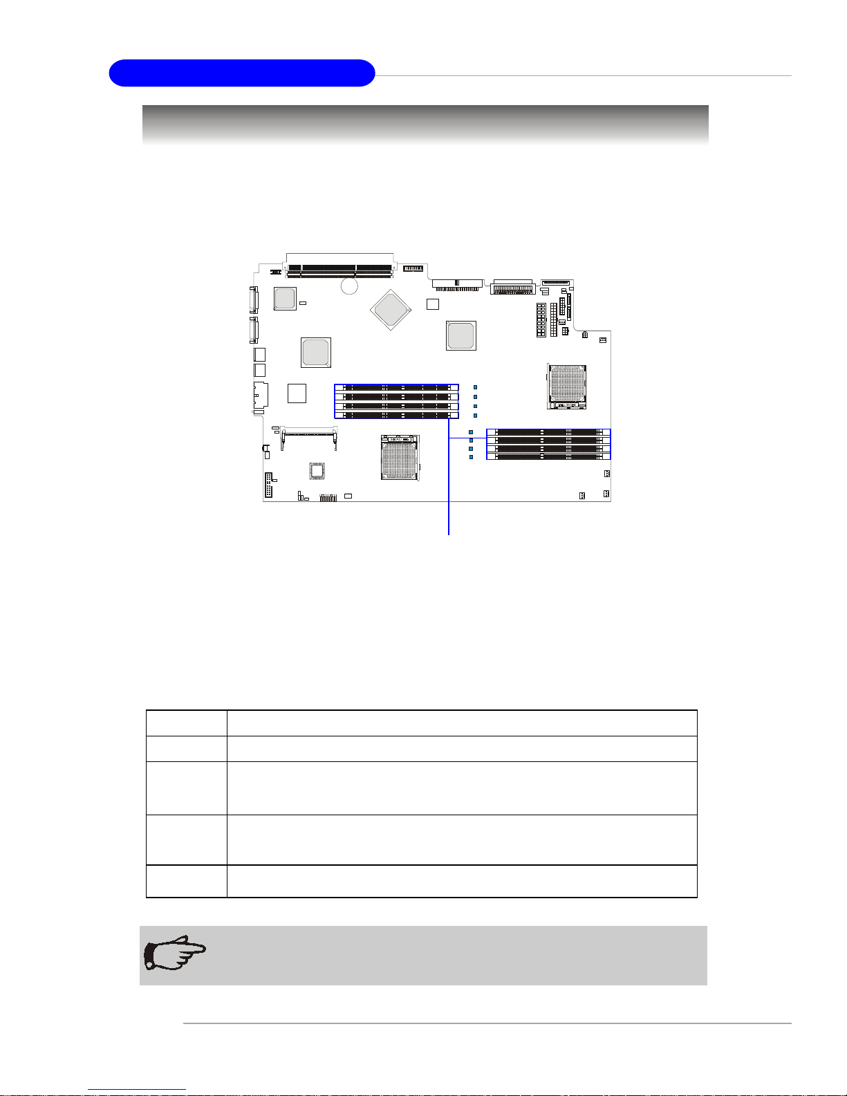
Mainboard Layout
Page 12

1-6
MS-9245 1U Rackmount Server
Unpack the package and check if all items listed below are present. If any item
contained in the package is damaged or missing, please contact your local dealer for
replacement. In addition, keep the box and packing materials for possible future use.
Your MS-9245 1U Rackmount Server Barebone package should contain the
following items:
Packing Checklist
* MS-9245 1U Rackmount Server x 1
(including an MS-9145 mainboard, an MS-9549 BMC card, a Power
Supply and a Fan Duct)
* Heatsink x 2
* 6”32 x 5 screw x 8
* HDD tray set (2 in a set, IDE model) x 2
* Rail Kit x 1
(including two rails and cable ties)
* User’s Guide x 1
* Installation Floppy Disk x 1
* Server Driver CD x 1
* iConsole Suite CD (optional) x 1
Page 13
1-7
Getting Started
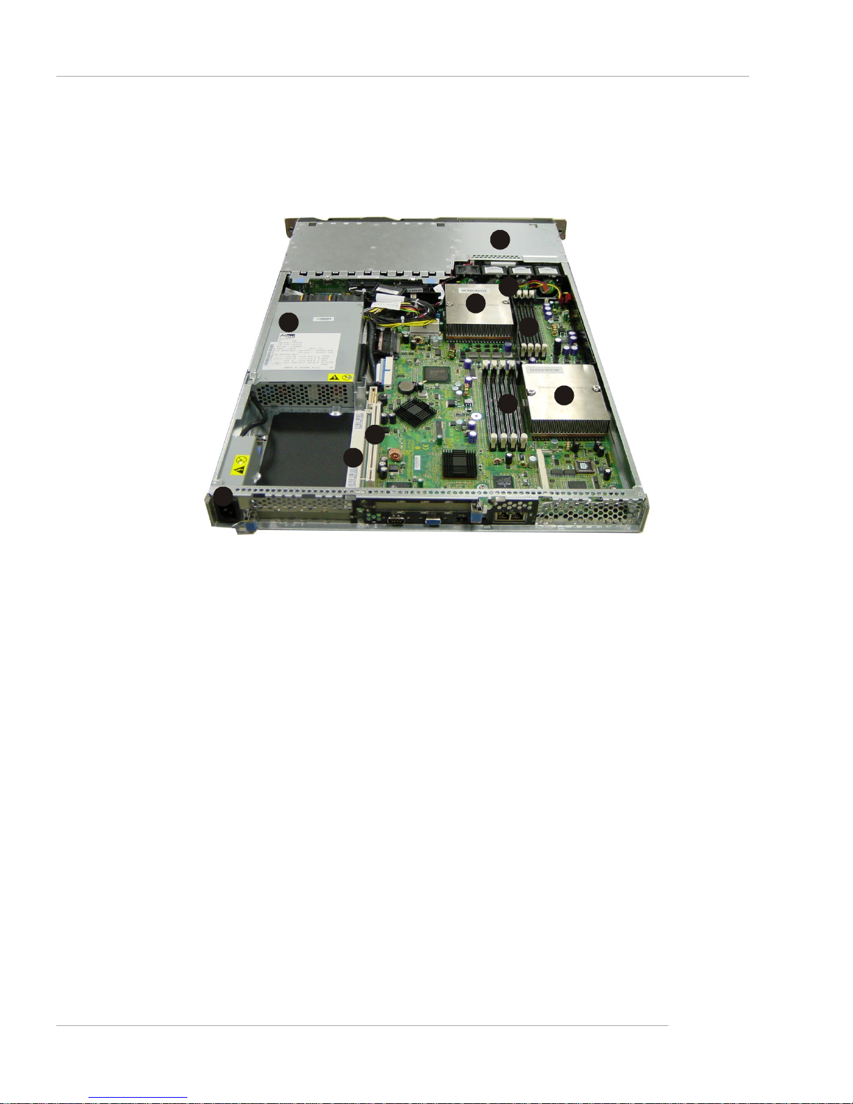
Front View
This section shows the configuration of the MS-9245 from different angles,
and the connectors and buttons on the front and back panel.
System Configuration
1. Slim CD-ROM (optional)
2. Hot Swap SCSI (or S-AT A) HDD: HDD 1 (ID0)
3. Hot Swap SCSI (or S-AT A) HDD: HDD 2 (ID1)
4. USB Port 1
5. USB Port 2
6. (from left to right) IDE HDD Activity LED, Location LED,
Info LED & Error LED**
7. Reset Button
8. Power Button
9. Power LED*
1
2
5
3
4
6
7 8
9
Page 14
1-8
MS-9245 1U Rackmount Server
Rear View
1. AC Power Connector
2. Half Length PCI Slot 2
3. Full Length PCI Slot 1
4. Serial Port
5. VGA Port
6. (from left to right) USB Port 3 & USB Port 4
7. (from left to right) Gbit Port 2 & Gbit Port 1
8. Power LED*
9. NMI Switch
10.Error LED**
1
2
5
3
4
6
7 8
9
10
NOTE
* Please refer to Table 1. MS-9245 Front Bezel & Rear I/O LEDs
Definitions for more information on Power LED.
** Please refer to Table 2. MS-9245 System Error and Diagnostic
LEDs Definitions for more information on Error LED.
Page 15

1-9
Getting Started
Table 1. MS-9245 Front Bezel & Rear I/O LEDs Definitions
LED Color State Description
ON System operating Green
Blink
System main power off and
standby power on
Power
OFF OFF AC power removed
Green Random blink IDE HDD access activity IDE HDD Activity
OFF OFF No di sk activity
Amber ON Some component error/failure Error
OFF OFF System normal operation
Blue ON Identify active via iConsole
command
Location
(Controlled by MSI
iConsole AP only)
OFF OFF No identification
Information
Amber Reserved for new BIOS function
upgrade
Green Random blink HDD access activity Swappable SCSI
HDD Access
OFF OFF No di sk activity
Page 16

1-10
MS-9245 1U Rackmount Server
Table 2. MS-9245 System Error and Diagnostic LEDs Definitions
Diagnostic LEDs
Diagnostic LEDs use signal display to help users understand their system. When
POST or Service Processor detects an error, the corresponding LEDs light up to alert
the user to the condition and help service personnel identify the failing component. A
system error single LED on the front panel and in the rear of the system first alters the
users that an error has occurred. Service personnel next check inside the system to
determine which subsystem has an error LED lit. This information helps the service
personnel to locate the failing component for replacement. The full failing path remians
lit until POST no longer exists or the error is fixed.
Item Error LED Diagnostic LED Description/Symptoms
1 OFF OFF Normal operation
2 ON CPU Error LED ON Processor related prob lems
3 ON SCSI Error LED ON SCSI hard drive Error/failu re
4 ON FAN Error LED ON Fan failu re
5 ON Memory Error LED ON Memory error/failure
6 ON N/A Power supply error/failure
Page 17

1-11
Getting Started
The Rear Panel provides the following connectors:
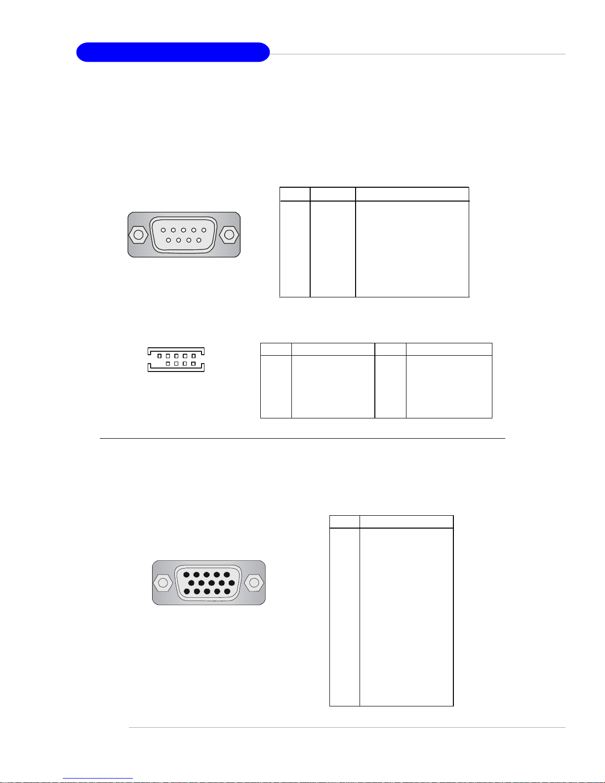
USB Connectors
The mainboard provides an UHCI (Universal Host Controller Interface) Universal Serial Bus root for attaching USB devices such as keyboard, mouse or other USBcompatible devices. You can plug the USB device directly into ths connector.
USB Port
1 2 3 4
LAN (RJ-45) Jacks: Giga-bit LAN
The mainboard provides two standard RJ-45 jacks for connection to Local
Area Network (LAN). Giga-bit LAN enables data to be transferred at 1000, 100 or
10Mbps. You can connect a network cable to either LAN jack.
Giga-bit LAN Pin Definition
PIN SIGNAL DESCRIPTION
1 D0P Differential Pair 0+
2 D0N Differential Pair 03 D1P Differential Pair 1+
4 D2P Differential Pair 2+
5 D2N Differential Pair 26 D1N Differential Pair 17 D3P Differential Pair 3+
8 D3N Differential Pair 3-
PIN SIGNAL DESCRIPTION
1 VCC +5V
2 -Data 0 Negative Data Channel 0
3 +Data0 Positive Data Channel 0
4 GND Ground
USB Port Description
Page 18
1-12
MS-9245 1U Rackmount Server
VGA Connector
The mainboard provides a DB 15-pin female connector to connect a VGA
monitor.
5 1
15 11
VGA Connector
(DB 15-pin)
Pin Signal Description
1 RED
2 GREEN
3 BLUE
4 N/C
5 GND
6 GND
7 GND
8 GND
9 +5V
10 GND
1 1 N/C
12 SDA
13 Horizontal Sync
14 Vertical Sync
15 SCL
Serial Port Connectors: COM 1 & COM 2 (optional)
The mainboard offers two 9-pin DIN connectors as serial ports COM 1 and COM
2. The ports are 16550A high speed communication ports that send/receive 16 bytes
FIFOs. You can attach a serial mouse or other serial devices directly to them.
COM 1
1 2 3 4 5
6 7 8 9
PIN SIGNAL DESCRIPTION
1 DCD Data Carry Detect
2 SIN Serial In or Receive Data
3 SOUT Serial Out or Transmit Data
4 DTR Data T erminal Ready)
5 GND Ground
6 DSR Data Set Ready
7 RTS Request To Send
8 CTS Clear To Send
9 RI Ring Indicate
COM 1 Pin Definition
COM 2
8 6 4 2
9 7 5 3 1
PIN DESCRIPTION PIN DESCRIPTION
1 Data Carrier Detect 2 Receive Data
3 Transmit Data 4 Data T erminal Ready
5 Ground 6 Data Set Ready
7 Request to Send 8 Clear to Send
9 Ring Indicator 1 0 Ground
COM 2 Pin Definition
Page 19
1-13
Getting Started
Top Vie w
1. Proprietary Power Supply
2. Slim CD-ROM Drive
3. DIMM Slots
4. PCI Slots
5. Heatsinks
6. Fan Duct
7. AC Power Connector
1
4
6
5
2
3
5
7
3
4
Page 20

2-1
Hardware Setup
Chapter 2. Hardware
Setup
Hardware Setup
This chapter provides you with the information about hardware setup procedures. While doing the installation, be careful in
holding the components and follow the installation procedures. For
some components, if you install in the wrong orientation, the components will not work properly.
Use a grounded wrist strap before handling computer
components. Static electricity may damage the components.
Page 21
2-2
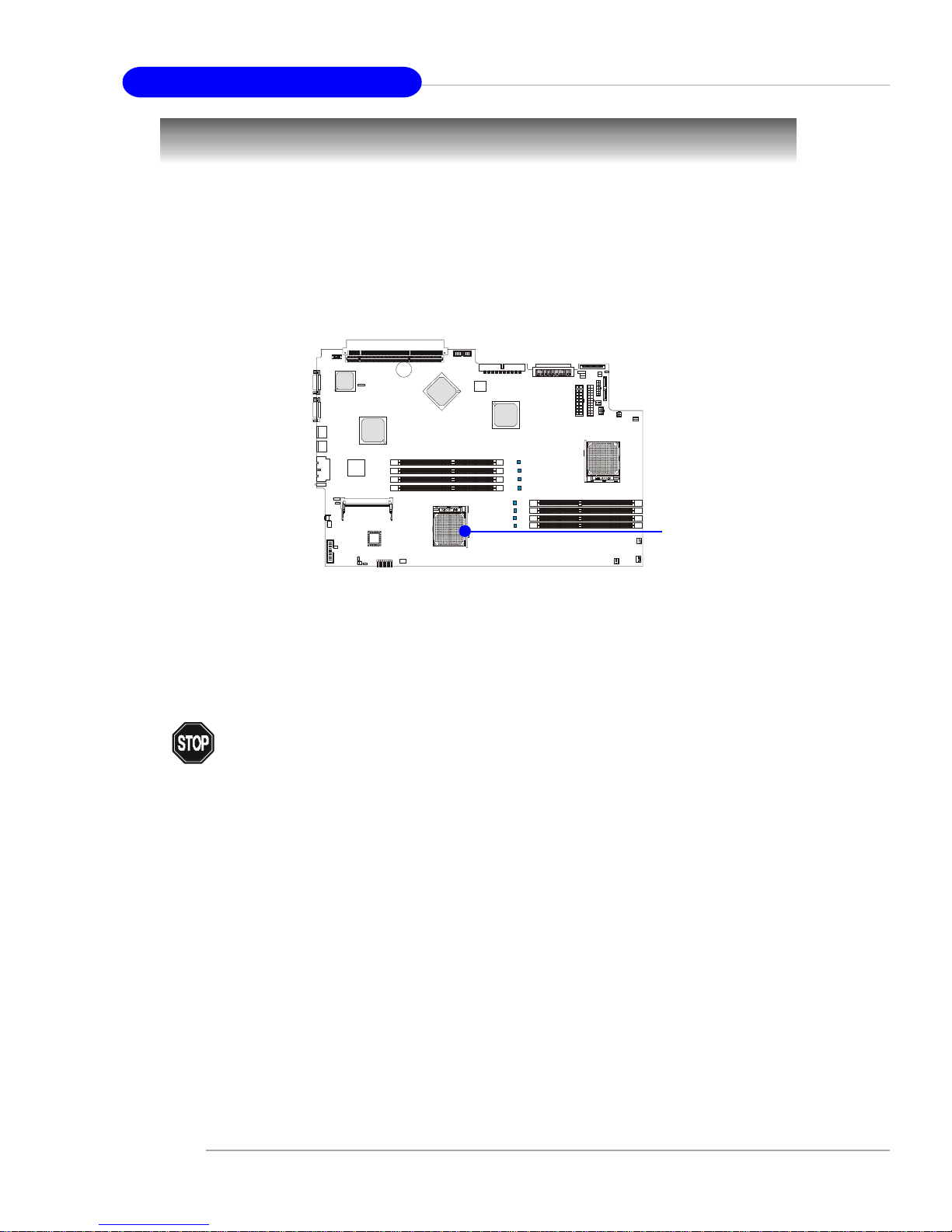
MS-9245 1U Rackmount Server
The mainboard supports Single AMD® Opteron UP or Dual AMD® Opteron DP™
processor(s). The mainboard uses two CPU sockets called Socket 940 for easy CPU
installation. Y ou can install SINGLE or DUAL CPUs on the mainboard to meet your own
needs. Keep the following points in mind before installing CPU(s):
1. If SINGLE CPU is intended, always install the CPU on the U1 socket.
2. To install DUAL CPUs on the board, you must use the same type/
stepping of AMD Opteron DP™ CPUs running at the same
frequency.
Central Processing Unit: CPU
As processor technology pushes to faster speeds and higher performance,
thermal management becomes increasingly crucial when building computer systems.
Maintaining the proper thermal environment is key to reliable operation. As such, the
processor must be maintained in the specified thermal requirements.
You need to add thermal grease between the CPU and heatsink to improve heat
dissipation. Then, make sure that the CPU and heatsink are securely fastened and in
good contact with each other. These are needed to prevent damaging the processor
and ensuring reliable operation. If you want to get more information on the proper
cooling, you can visit AMD’s website for reference.
WARNING! Thermal Issue for CPU
U1
B
A
T
T
+
B
I
O
S
Page 22
2-3
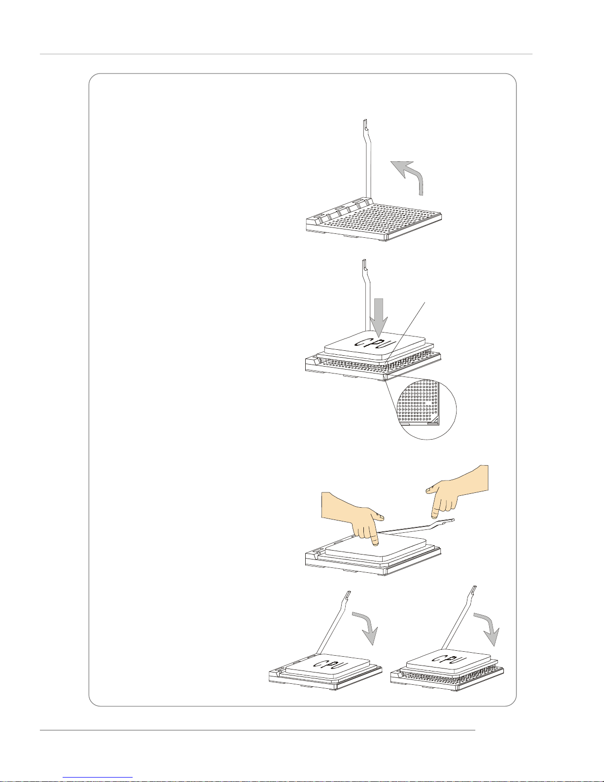
Hardware Setup
1. Make sure that the computer is
turned off, and the power cord
disconnected before installing
the CPU.
2. Pull the lever sideways away
from the socket, and raise it up
to a 90-degree angle.
3. Locate the cut edge of the CPU.
When the CPU is installed into the
socket, this cut edge should be
aligned with the corner marking
an arrow on the Socket 940.
Please note that the CPU can only
fit in a correct orientation. DO
NOT use force to install the CPU
into the socket.
4. Place the CPU onto the socket
and press it down firmly into the
socket. The pins of the CPU
should be embedded into the
socket completely.
5. Close the lever to secure the
CPU. Do not close the level until
the CPU’s pins are fully inserted;
otherwise, the pins may be
damaged.
CPU Installation Procedures for Socket 940
XO
Open Lever
S
l
i
d
i
n
g
P
l
a
t
e
Close
Lever
Press down
the CPU
Cut edge
Corner marking
an arrow
Page 23
2-4
MS-9245 1U Rackmount Server
B
A
T
T
+
B
I
O
S
The mainboard supports up to eight registered ECC DDR200/266/333/400 DIMMs
providing up to 16GB of memory. Each DIMM slot supports up to a maximum size of
2GB. You can install either single- or double-sided modules to meet your own needs.
Memory
DDR DIMM Slots
DIMM Module Combination
You can install either one or two DIMM modules on the slots. Use Slot 1, 3, 6
or 8 for single DDR module installation. If DDR modules are installed on Slot
5 ~ 8, CPU2 must be installed.
Memory modules can be installed in any combination as follows:
NOTE
Memory modules “in pairs” must be of the same type and size.
Option Memory Modules Installed
1 Slot 1&2, Slot 3&4, Slot 5&6, Slot 7&8
2 Slot 1&2&3&4, Slot 1&2&5&6, Slot 1&2&7&8, Slot 3&4&5&6, Slot 3&4&7&8,
Slot 5&6&7&8
3 Slot 1&2&3&4&5&6, Slot 1&2&3&4&7&8, Slot 1&2&5&6&7&8,
Slot 3&4&5&6&7&8
4 Slot 1&2&3&4&5&6&7&8
Page 24
2-5
Hardware Setup
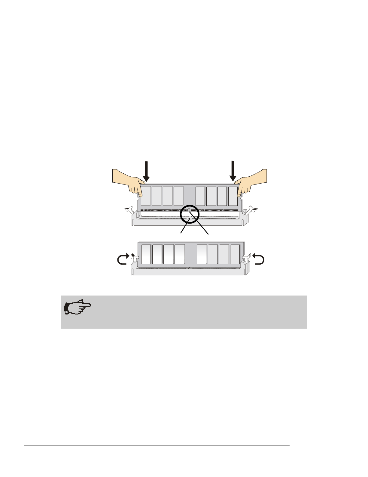
Installing DDR Modules
1. The DDR DIMM has only one notch on the center of module. The module will only
fit in the right orientation.
2. Insert the DIMM memory module vertically into the DIMM slot. Then push it in until
the golden finger on the memory module is deeply inserted in the socket.
3. The plastic clip at each side of the DIMM slot will automatically close.
Volt
Notch
NOTE
You can barely see the golden finger if the module is properly inserted
in the socket.
Page 25
2-6
MS-9245 1U Rackmount Server
Power Supply
The mainboard supports SSI power supply for the power system. Before
inserting the power supply connector, always make sure that all components are
installed properly to ensure that no damage will be caused.
18-Pin Main Power Supply Connector: J10
This connector provides power supply to the system board.
14-Pin Standby and Status Control Connector: J11
This connector provides power supply to the system board.
24-Pin SCSI Power and I2C Connector: J12
This connector is an optional power connector to provide power output to the
SCSI HDD.
4-Pin CD-ROM Power Connector: J14
This connector provides power supply to the CD-ROM Drive.
6-Pin Front Plane USB Connector: J15
This connector provides power supply to the front USB ports.
J12
12
1
24
13
2
4
1
J14
3
J10
1
10
9
18
1
14
4
7
J11
1
3
J15
6
4
Page 26

2-7
Hardware Setup
J10
Molex_44472-1853
RET1
5
12V_1
1
5V_1
15
MH1
MH1
MH2
MH2
12V_2
2
12V_3
3
12V_4
4
5V_2
16
5V_3
17
5V_4
18
RET2
6
RET3
7
RET4
8
RET5
9
RET6
10
RET7
11
RET8
12
RET9
13
RET10
14
J11
Molex_43045-1413
-ON_+OFF
1
OC
8
+5VSB
5
+5VSB2
6
+5VSB_RET
11
-EPOW
2
-FAN_FAULT
3
DCGOOD/-POR
4
-FAN_HS
7
SDA
9
SCL
10
SPARE1
13
SPARE2
14
+5VSB_RET2
12
MH1
MH1
MH2
MH2
J12
Molex_43045-2413
I2C_A0
17
12V_1
1
12V_2
3
12V_3
5
12V_4
7
I2C_A1
18
I2C_A2
19
I2C_CLK
21
I2C_DATA
23
I2C_INT
24
GND1
2
GND2
4
GND3
6
GND4
8
5V_1
11
5V_2
13
5V_3
15
RESET
10
3P4V/NC
20
GND6
14
GND7
16
GND8
22
MH1
MH1
MH2
MH2
PRES_DET#
9
GND5
12
J14
Molex_43045-0414
12V1GND1
2
GND2
3
5V
4
MH1
MH1
MH2
MH2
J15
CON2X3
C1
1
C2
2
C3
3
C4
4
C5
5
C6
6
Page 27

2-8
MS-9245 1U Rackmount Server
Connectors
SM Card 3rd I2C Bus Connector: JSMB1
The mainboard provides one I2C (also known as I2C) Bus connector for users
to connect to System Management Bus (SMBus) interface.
JSMB1
1
3
PIN SIGNAL
1DATA
2 CLK
3ALT#
JSMB1 Pin Definition
J13
2
1
25
26
Pin Description Pin Description
1 GND 2 SM_PWRLED#
3 GND 4 FP2SW_RST#
5 GND 6 Unused
7 +5VSB 8 Unused
9 +5VSB 10 SMB_2_DATA
11 +5VSB 12 SMB_2_CLK
13 Unused 14 GND
15 +5V 16 SM_FP_DET#
1 7 +5V 1 8 USB1_OC_L
19 +5V 20 SB_GPIO14
2 1 +5V 2 2 SM_LED4_SEL
23 GND 24 FP2SW_PWRBTN#
25 GND 26 Unused
J13 Pin Definition
Front Panel Connector: J13
The mainboard provides one front panel connector for electrical connection to
the front panel switches and LEDs.
Page 28

2-9
Hardware Setup
B
A
T
T
+
B
I
O
S
Hard Disk Connector: IDE
The mainboard has a 32-bit Enhanced PCI IDE and Ultra DMA 33/66/100/133
controller that provides PIO mode 0~4, Bus Master, and Ultra DMA 33/66/100/133
function. You can connect up to two hard disk drives, CD-ROM, 120MB Floppy
(reserved for future BIOS) and other devices.
The IDE can connect a Master and a Slave drive. You must configure second
hard drive to Slave mode by setting the jumper accordingly.
IDE
NOTE
If you install two hard disks on cable, you must configure the second
drive to Slave mode by setting its jumper. Refer to the hard disk documentation supplied by hard disk vendors for jumper setting instructions.
Page 29

2-10
MS-9245 1U Rackmount Server
B
A
T
T
+
B
I
O
S
Fan Power Connectors: SF AN1/SFAN2/SFAN3/SFAN4/SF AN5
The SFAN1/SFAN2/SFAN3/SFAN4/SFAN5 (system fans) support system cooling fan with +12V. It supports three-pin head connector. When connecting the wire
to the connectors, always take note that the red wire is the positive and should be
connected to the +12V, the black wire is Ground and should be connected to GND. If
the mainboard has a System Hardware Monitor chipset on-board, you must use a
specially designed fan with speed sensor to take advantage of the CPU fan control.
NOTE
1. Always consult the vendors for proper CPU cooling fan.
2. SFAN supports the fan control. MS-9245 will automatically control
the CPU fan speed according to the system temperature.
SF AN3
Sensor
+12V
GND
SF AN4
Sensor
+12V
GND
SFAN5
Sensor
+12V
GND
SF AN1
Sensor
+12V
GND
SF AN2
GND
+12V
Sensor
Page 30

2-11
Hardware Setup
PIN SIGNAL PIN SIGNAL
1 GND 2 TXP
3 TXN 4 GND
5 RXN 6 RXP
7 GND
Pin Definition
Serial ATA Connectors: JSA_11, JSA_22 (Optional)
The mainboard provides optional Serial ATA connectors supported by Silicon
Image Sil3512 single-chip PCI to 2-port Serial ATA host controller.
Connect to JSA_11/JSA_22
Take out the dust cover and
connect to the hard disk
devices
Optional Serial A TA cable
MSI Reminds You...
Please do not fold the Serial A TA cable into 90-degree angle. Otherwise,
the loss of data may occur during transmission.
Rear Status LED: J20
The LED shows the error and power status.
Error LED (Amber)
Power LED (Green)
JSA_22
JSA_11
7
1
7
1
Page 31

2-12
MS-9245 1U Rackmount Server
Ultra320 SCSI Connector: SCSI 1 (Optional)
SCSI (Small Computer System Interface) is a hardware interface that allows
for connection of up to 15 peripheral devices. The mainboard provides one SCSI
channel (SCSI 1) for you to connect SCSI devices such as SCSI hard disks.
SCSI 1
1
35
34
68
Pin Description Pin Description
1 +DB(12) 35 -DB(12)
2 +DB(13) 36 -DB(13)
3 +DB(14) 37 -DB(14)
4 +DB(15) 38 -DB(15)
5 +DB(P1) 39 -DB(P1)
6 +DB(0) 40 -DB(0)
7 +DB(1) 41 -DB(1)
8 +DB(2) 42 -DB(2)
9 +DB(3) 43 -DB(3)
10 +DB(4) 44 -DB(4)
11 +DB(5) 45 -DB(5)
12 +DB(6) 46 -DB(6)
13 +DB(7) 47 -DB(7)
14 +DB(P) 48 -DB(P)
15 GROUND 49 GROUND
16 DIFFSENS 50 GROUND
17 TERMPWR 51 TERMPWR
18 TERMPWR 52 TERMPWR
19 RESERVED 53 RESERVED
20 GROUND 54 GROUND
21 +ATN 55 -ATN
22 GROUND 56 GROUND
2 3 +BSY 5 7 -BSY
24 +ACK 58 -ACK
25 +RST 59 -RST
26 +MSG 60 -MST
27 +SEL 61 -SEL
28 +C/D 62 -C/D
29 +REQ 63 -REQ
30 +I/O 64 -I/O
31 +DB(8) 65 -DB(8)
32 +DB(9) 66 -DB(9)
33 +DB(10) 67 -DB(10)
34 +DB(11) 68 -DB(11)
68-Pin Ultra320 SCSI Connector
Page 32
2-13
Hardware Setup
SODIMM144__8MMP
J16
COM1_DI(I)
1
COM1_RST#(O)
3
COM1_DCD#(I)
5
COM1_RI#(I)
7
COM1_CTS#(I)
9
COM1_DTR#(O)
13
COM1_DSR#(I)
15
COM1_EN/SW#(O)
17
COM2_EN/SW#(O)
19
COM_BUS_EXCH(O)
21
FAN_TACH3(I)
33
POST/I2C_ACK#(O)
23
5VSB_VDD_ANALOG
25
FAN_TACH0(I)
27
FAN_TACH1(I)
29
FAN_TACH2(I)
31
FAN_TACH4(I)
35
FAN_TACH5(I)
37
NC
39
NC
41
NC
43
NC
45
NC
47
NC
49
GND_ANALOG
51
I2C_0_SDA
53
I2C_0_SCL
55
I2C_0_INT#
57
3VSB_ANALOG
59
I2C_2_SDA
61
I2C_2_SCL
63
I2C_INT#(I)
65
SB_PWR_PG(I)
67
Main_PWR_PG(I)
69
ANALOG_VOLT0(I)
71
ANALOG_VOLT1(I)
73
ANALOG_VOLT2(I)
75
ANALOG_VOLT3(I)
77
ANALOG_VOLT4(I)
79
ANALOG_VOLT5(I)
81
ANALOG_VOLT6(I)
83
ANALOG_VOLT7(I)_BAT
85
RTS_SEN_EN(O)
87
3.3VSB_ANALOG
89
NC
91
LPC_AD0
2
COM1_DO(O)
11
INSERT_DET(I)
93
BMC_VER0(O)
95
BMC_VER1(O)
97
PLAN_LVL0(I)
99
PLAN_LVL1(I)
101
PLAN_LVL2(I)
103
PLAN_LVL3(I)
105
SYS_ID0(I)
107
SYS_ID1(I)
109
SYS_ID2(I)
111
SYS_ID3(I)
113
SYS_ID4(I)
115
NC
117
NC
119
GND
121
485+
123
485-
125
GND
127
PWR_BTN_IN(I)
129
PWR_BTN_OUT(O)
131
BMC_Heartbeat(O)
133
BMC_SMI#
135
COM_EXCH_DIS(O)
139
COM_SHUT(O)
141
5VSB
143
LPC_AD1
4
LPC_AD2
6
LPC_AD3
8
GND
10
(I)LPC_CLK
12
LPC_RST#
14
LPC_FRAME#
16
(O)LPC_INT#
20
GND
18
(O)LPC_DRQ#
22
(I)POST/I2C_REQ#
24
5VSB
26
(O)FAN_PWM0
28
(O)FAN_PWM1
30
(O)FAN_PWM2
32
(O)FAN_PWM3
34
(O)FAN_PWM4
36
(O)FAN_PWM5
38
NC
40
NC
42
(I)GP_INT1#
44
(I)GP_INT2#
46
(I)GP_INT3#
48
(I)GP_INT4#
50
GND
52
I2C_1_SDA
54
I2C_1_SCL
56
(I)I2C_1_INT#
58
3.3VSB
60
I2C_3_SDA
62
I2C_3_SCL
64
(I)I2C_3_INT#
66
EPOW#
68
(I)SYS_RST#
70
(O)SYS_RST_OUT
72
(O)SYS_PWRON_OUT
74
(I)SYS_PWRON_IN
76
(O)BMC_WD#
78
(I)FEA_DET0
80
(I)FEA_DET1
82
(O)I2C_0_RST#
84
(O)I2C_2_RST#
86
(O)I2C_2_MUX_DIS#
88
3.3VSB
90
NC
92
LED0
94
LED1
96
LED2
98
LED3
100
LED4
102
LED5
104
LED6
106
NC
110
NC
112
NC
114
NC
116
NC
118
NC
120
GND
122
NC
124
NC
126
GND
128
NC
130
NC
132
(I)SYS_RTC
134
(I)REM_BTN_IN
136
(I)HD_ACT#
138
(I)I2C_DIS_ALL
140
(I)I2C_MEM_SW
142
5VSB
144
LED7
108
SYS_NMI#(I)
137
1
2
J16
143
144
SO DIMM (Small Outline DIMM): J16
The SO DIMM has 144 pins and supports a full 64-bit transfer. It is specifically
designed for users to install MSI’s proprietary server management tool -- MSI BMC
(Baseboard Management Controller) card.
Page 33
2-14
MS-9245 1U Rackmount Server
PCI-X 100/133 Jumper: JPCIXB1
The jumper is used to set the channel B of 64-bit PCI bus (PCIX) to run at
100MHz or at 133MHz (for use with one PCI-X 133 device).
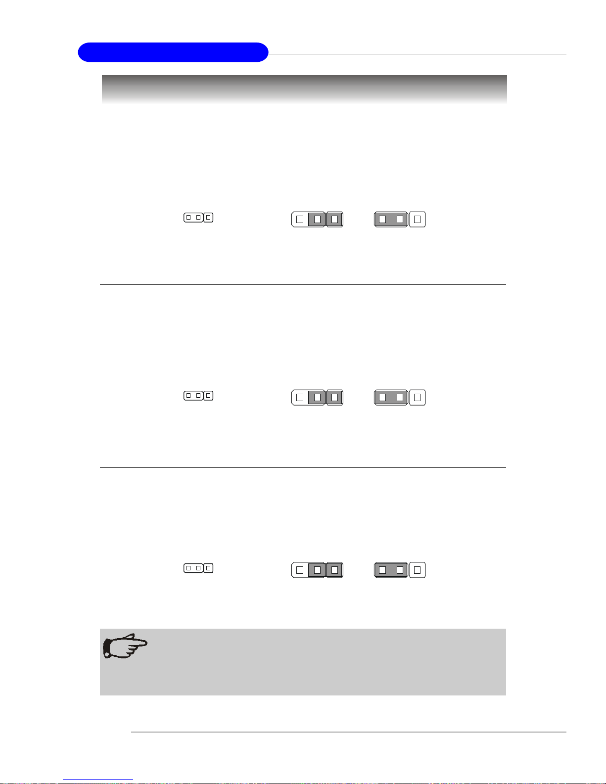
Jumpers
Clear CMOS Jumper: JBA T1
If you want to clear the system configuration, use the JBAT1 (Clear CMOS
Jumper ) to clear data.
Keep Data Clear Data
3
13
1
NOTE
You can clear CMOS by shorting 2-3 pin while the system is off. Then
return to 1-2 pin position. Avoid clearing the CMOS while the system is
on; it will damage the mainboard.
1
JBAT1
100MHz 133MHz
3
13
1
1
JPCIXB1
Boot Block Jumper: JBBF1
Users can short connect pin#2-3 to recover the system BIOS with a Recovery
Floppy. When the system is done with the job, the buzzer will beep to notify the user
and set the jumper to its normal state (pin#1-2 short connected).
Normal
Recovery
3
13
1
1
JBBF1
Page 34

2-15
Hardware Setup
PCI Interrupt Request Routing
The IRQ, acronym of interrupt request line and pronounced I-R-Q, are hardware lines over which devices can send interrupt signals to the microprocessor.
The PCI IRQ pins are typically connected to the PCI bus INT A# ~ INT D# pins as
follows:
PCI Slots
Two PCI slots allow you to insert the expansion cards to meet your needs.
When adding or removing expansion cards, make sure that you unplug the power
supply first. Meanwhile, read the documentation for the expansion card to make any
necessary hardware or software settings for the expansion card, such as jumpers,
switches or BIOS configuration.
The motherboard provides two 64-bit PCI-X 100/133MHz slots. One is full
length and the other is half length.
Slots
Primary IDE Interrupt: IRQ14 (for AMD811 1)
Secondary IDE Interrupt: IRQ15 (for AMD8111)
IRQ Routing
Devices Order 1 Order 2 Order 3 Order 4
PCI Slot 1 INT A# INT B# INT C# INT D#
PCI Slot 2 I NT D# INT A# INT B# INT C#
LAN INT A# INT B#
VGA INT A#
SCSI INT C#
Page 35

3-1
BIOS Setup
Chapter 3. BIOS Setup
BIOS Setup
This chapter provides information on the BIOS Setup program
and allows you to configure the system for optimum use. You may
need to run the Setup program when:
An error message appears on the screen during the system boot-
ing up, and requests you to run SETUP.
You want to change the default settings for customized features.
MSI Reminds You...
1. The items under each BIOS category described in this chapter
are under continuous update for better system performance.
Therefore, the description may be slightly different from the lat-
est BIOS and should be held for reference only.
2. Upon boot-up, the 1st line appearing after the memory count is
the BIOS version. It is usually in the format:
P9145MS V1.0 150304 where:
1st digit refers to BIOS maker as A = AMI, W = AWARD,
and P = PHOENIX.
2nd - 5th digit refers to the model number.
6th - 7th digit refers to the customer as MS = all standard
customers.
V1.0 refers to the BIOS version.
150304 refers to the date this BIOS was released.
Page 36

3-2
MS-9245 1U Rackmount Server
Entering Setup
Control Keys
Power on the computer and the system will start POST (Power On Self Test)
process. When the message below appears on the screen, press <F2> key to enter
Setup.
Press F2 to enter SETUP
If the message disappears before you respond and you still wish to enter
Setup, restart the system by turning it OFF and On or pressing the RESET button. You
may also restart the system by simultaneously pressing <Ctrl>, <Alt>, and <Delete>
keys.
Key
<F1> or <Alt-H>
<Esc>
↔ arrow keys
↑ or ↓ arrow keys
<Tab> or <Shift-Tab>
<Home> or <End>
<PgUp> or <PgDn>
<F5> or <->
<F6> or <+> or <Space>
<F9>
<F10>
<Enter>
Function
General Help window
Exit this menu
Select a different menu
Move cursor up and down
Cycle cursor up and down
Move cursor to top or bottom of window
Move cursor to next or previous page
Select the Previous Value for the field
Select the Next Value for the field
Load the Default Configuration values for this menu
Save and exit
Execute Command or Enter Submenu
Page 37

3-3
BIOS Setup
Getting Help
After entering the Setup menu, the first menu you will see is the Main Menu.
Main Menu
The main menu lists the setup functions you can make changes to. You can
use the arrow keys ( ↑↓ ) to select the item. The on-line description of the highlighted
setup function is displayed at the bottom of the screen.
Sub-Menu
If you find a right pointer symbol (as shown in the right view) appears to the
left of certain fields that means a sub-menu can be launched from this field. A submenu contains additional options for a field parameter. You can use arrow keys ( ↑↓
) to highlight the field and press <Enter> to call up the sub-menu. Then you can use
the control keys to enter values and move from field to field within a sub-menu. If you
want to return to the main menu, just press the
<Esc >.
General Help <F1>
The BIOS setup program provides a General
Help screen. You can call up this screen from any
menu by simply pressing <F1>. The Help screen
lists the appropriate keys to use and the possible
selections for the highlighted item. Press <Esc> to exit the Help screen.
8IDE Primary Master
8IDE Primary Slave
8IDE Secondary Master
8IDE Secondary Slave
Page 38

3-4
MS-9245 1U Rackmount Server
Once you enter PhoenixBIOS Setup Utility, the Main Menu will appear on the
screen. On the Main Menu screen, you will see basic BIOS settings including system
time & date, and the setup categories the BIOS supplies. Use Arrow keys to move
among the items and menus, and make changes to the settings.
Main Menu
Use this menu for basic system configurations, such as time, date etc.
Advanced Menu
Use this menu to set up the items of special enhanced features available on your
system’s chipset.
Security Menu
Use this menu to set Supervisor and User Passwords and the Backup and VirusCheck reminders.
The Menu Bar
System TimeSystem Time
System TimeSystem Time
System Time
[09:10:11][09:10:11]
[09:10:11][09:10:11]
[09:10:11]
System DateSystem Date
System DateSystem Date
System Date
[05/25/2003][05/25/2003]
[05/25/2003][05/25/2003]
[05/25/2003]
8IDE Primary Master [None]
8IDE Primary Slave [None]
8IDE Secondary Master [CD-ROM]
8IDE Secondary Slave [None]
Large Disk Access Mode :Large Disk Access Mode :
Large Disk Access Mode :Large Disk Access Mode :
Large Disk Access Mode :
[DOS][DOS]
[DOS][DOS]
[DOS]
Boot Summary Screen :Boot Summary Screen :
Boot Summary Screen :Boot Summary Screen :
Boot Summary Screen :
[Disabled][Disabled]
[Disabled][Disabled]
[Disabled]
System Memory :System Memory :
System Memory :System Memory :
System Memory :
624KB624KB
624KB624KB
624KB
Extended MemoryExtended Memory
Extended MemoryExtended Memory
Extended Memory
::
::
:
510MB510MB
510MB510MB
510MB
PhoenixBIOS Setup Utility
Main Main
Main Main
Main
Advanced Security Power Boot Exit Advanced Security Power Boot Exit
Advanced Security Power Boot Exit Advanced Security Power Boot Exit
Advanced Security Power Boot Exit
<Tab>, <Shift+Tab>, or<Tab>, <Shift+Tab>, or
<Tab>, <Shift+Tab>, or<Tab>, <Shift+Tab>, or
<Tab>, <Shift+Tab>, or
<Enter> selects field.<Enter> selects field.
<Enter> selects field.<Enter> selects field.
<Enter> selects field.
Item Specific HelpItem Specific Help
Item Specific HelpItem Specific Help
Item Specific Help
F1 Help
↑↓ Select Item
-/+ Change Values F9 Setup Defaults
Esc Exit
↔ Select Menu
Enter Select Sub-Menu F10 Save and Exit
8
Page 39

3-5
BIOS Setup
Power Menu
Use this menu to specify your settings for power management.
Boot Menu
Use this menu to specify the priority of boot devices.
Exit Menu
This menu allows you to load the BIOS default values or factory default settings into
the BIOS and exit the BIOS setup utility with or without changes.
Page 40

3-6
MS-9245 1U Rackmount Server
The items inside the Main menu are for basic system information and
configuration. Each item includes none, one or more setup items. Use the Up/Down
arrow keys or <Tab> to highlight the item or field you want to modify and use the <+>
or <-> key to switch to the value you prefer.
System Time
The time format is <HH> <MM> <SS>.
System Date
The date format is <MM> <DD> <YYYY>.
Primary/Secondary Master/Slave
Press PgUp/<+> or PgDn/<-> to select [Manual], [None] or [Auto] type. Note that the
specifications of your drive must match with the drive table. The hard disk will not
work properly if you enter improper information for this category. If your hard disk
drive type is not matched or listed, you can use [Manual] to define your own drive
type manually.
If you select [Manual], related information is asked to be entered to the following
The Main Menu
F1 Help F1 Help
F1 Help F1 Help
F1 Help
↑↓ Select Item -/+ Change Values F9 Setup Defaults
Esc Exit Esc Exit
Esc Exit Esc Exit
Esc Exit
↔ Select Menu Select Sub-Menu F10 Save and Exit
System TimeSystem Time
System TimeSystem Time
System Time
[09:10:11][09:10:11]
[09:10:11][09:10:11]
[09:10:11]
System DateSystem Date
System DateSystem Date
System Date
[05/25/2003][05/25/2003]
[05/25/2003][05/25/2003]
[05/25/2003]
8IDE Primary Master [None]
8IDE Primary Slave [None]
8IDE Secondary Master [CD-ROM]
8IDE Secondary Slave [None]
Large Disk Access Mode :Large Disk Access Mode :
Large Disk Access Mode :Large Disk Access Mode :
Large Disk Access Mode :
[DOS][DOS]
[DOS][DOS]
[DOS]
Boot Summary Screen :Boot Summary Screen :
Boot Summary Screen :Boot Summary Screen :
Boot Summary Screen :
[Disabled][Disabled]
[Disabled][Disabled]
[Disabled]
System Memory :System Memory :
System Memory :System Memory :
System Memory :
624KB624KB
624KB624KB
624KB
Extended MemoryExtended Memory
Extended MemoryExtended Memory
Extended Memory
::
::
:
510MB510MB
510MB510MB
510MB
PhoenixBIOS Setup Utility
Main Main
Main Main
Main
Advanced Security Power Boot Exit Advanced Security Power Boot Exit
Advanced Security Power Boot Exit Advanced Security Power Boot Exit
Advanced Security Power Boot Exit
<Tab>, <Shift+Tab>, or<Tab>, <Shift+Tab>, or
<Tab>, <Shift+Tab>, or<Tab>, <Shift+Tab>, or
<Tab>, <Shift+Tab>, or
<Enter> selects field.<Enter> selects field.
<Enter> selects field.<Enter> selects field.
<Enter> selects field.
Item Specific HelpItem Specific Help
Item Specific HelpItem Specific Help
Item Specific Help
F1 Help
↑↓ Select Item
-/+ Change Values F9 Setup Defaults
Esc Exit
↔ Select Menu
Enter Select Sub-Menu F10 Save and Exit
8
Page 41

3-7
BIOS Setup
items. Enter the information directly from the keyboard. This information should be
provided in the documentation from your hard disk vendor or the system manufacturer.
Type Select how to define the HDD parameters
Multi-Sector Transfers Any selection except Disabled determines
the number of sectors transferred per block
LBA Mode Control Enabling LBA causes Logical Block Ad-
dressing to be used in place of Cylinders,
Heads and Sectors.
32-Bit I/O Enables 32-bit communication between
CPU and IDE card
Tranfer Mode Selects the method for transferring the data
between the hard disk and system memory
Ultra DMA Mode Indicates the type of Ultra DMA.
Large Disk Access Mode
Select DOS if you have DOS. Select Other if you have another operating system such
as UNIX. A large disk is one that has more than 1024 cylinders, more than 16 heads,
or more than 63 tracks per sector. Options: [DOS], [Other].
Boot Summary Screen
Selecting Enabled displays system summary screen during boot up. Options: [Enabled],
[Disabled].
System Memory
It displays amount of conventional memory detected during boot up.
Extended Memory
It displays the amount of extended memory detected during boot up.
Page 42

3-8
MS-9245 1U Rackmount Server
Items in the menu are divided into 7 sub-menus. Each sub-menu provides more
settings. To enter the sub-menu, highligh the sub-menu you want to configure and
press <Enter>.
The Advanced Menu
Install O/S
Select the operating system installed on your system which you will use most
commonly. Options: [Other], [Win95], [Win98], [WinMe], [Win2000].
Reset Configuration Data
Select [Yes] if you want to clear the Extended System configuration Data (ESCD)
area. Options: [Yes], [No].
Multiprocessor Specification
This item allows you to configure the MP Specification revision level. Some operating
systems will require 1.1 for compatibility reason. Options: [1.4], [1.1].
Quick Boot Mode
This feature allows the system skip certain tests while booting. This will decrease the
time needed to boot the system. Options: [Enabled], [Disabled].
IOMMU
This setting applies only to Linux systems only. Options: [Enabled], [Disabled].
Installed O/S :Installed O/S :
Installed O/S :Installed O/S :
Installed O/S :
[Other][Other]
[Other][Other]
[Other]
Reset Configuration Data :Reset Configuration Data :
Reset Configuration Data :Reset Configuration Data :
Reset Configuration Data :
[No][No]
[No][No]
[No]
Multiprocessor Specification :Multiprocessor Specification :
Multiprocessor Specification :Multiprocessor Specification :
Multiprocessor Specification :
[1.4][1.4]
[1.4][1.4]
[1.4]
QuickBoot Mode :QuickBoot Mode :
QuickBoot Mode :QuickBoot Mode :
QuickBoot Mode :
[Enabled][Enabled]
[Enabled][Enabled]
[Enabled]
IOMMU :IOMMU :
IOMMU :IOMMU :
IOMMU :
[Enabled][Enabled]
[Enabled][Enabled]
[Enabled]
8Chipset Configuration
8Keyboard Configuration
8I/O Device Configuration
8PCI Configuration
8Console Redirection
8POST Error Log
8IPMI
PhoenixBIOS Setup Utility
Select the operating sys-Select the operating sys-
Select the operating sys-Select the operating sys-
Select the operating sys-
tem installed on your sys-tem installed on your sys-
tem installed on your sys-tem installed on your sys-
tem installed on your sys-
tem which you will usetem which you will use
tem which you will usetem which you will use
tem which you will use
most commonly.most commonly.
most commonly.most commonly.
most commonly.
Note: An incorrect set-Note: An incorrect set-
Note: An incorrect set-Note: An incorrect set-
Note: An incorrect set-
ting can cause some op-ting can cause some op-
ting can cause some op-ting can cause some op-
ting can cause some op-
erating systems to displayerating systems to display
erating systems to displayerating systems to display
erating systems to display
unexpected behavior.unexpected behavior.
unexpected behavior.unexpected behavior.
unexpected behavior.
Item Specific HelpItem Specific Help
Item Specific HelpItem Specific Help
Item Specific Help
Main Main
Main Main
Main
AdvancedAdvanced
AdvancedAdvanced
Advanced
Security Power Boot Exit Security Power Boot Exit
Security Power Boot Exit Security Power Boot Exit
Security Power Boot Exit
F1 Help
↑↓ Select Item
-/+ Change Values F9 Setup Defaults
Esc Exit
↔ Select Menu
Enter Select Sub-Menu F10 Save and Exit
8
Page 43

3-9
BIOS Setup
Chipset Configuration
The sub-menu is used to configure chipset features for optimal system performance.
Dram Bank Interleave
Interleave memory blocks across dram chip selects. Options: [Auto], [Disabled].
Node Memory Interleave
Interleave memory blocks across Processor Nodes. BIOS will AUTO detect the
capability of Memory System. Options: [Disabled], [AUTO].
HPET Timer
This item allows you to enable/disable HPET high precision event timer. Setting
to Disabled will turn off the device and remove it from the ACPI namespace.
Options: [Enabled], [Disabled].
HT Link Frequency
This setting specifies the HT (HyperTransport) frequency between CPU0 &
CPU1. Setting options: [800MHz], [1GHz].
ECC
This is a global enable function for all blocks within CPU core and North Bridge.
After loading setup defaults, restart and enter setup to access Dram ECC setup
options. Options: [Enabled], [Disabled].
Setting items on this menu to incorrect values may causeSetting items on this menu to incorrect values may cause
Setting items on this menu to incorrect values may causeSetting items on this menu to incorrect values may cause
Setting items on this menu to incorrect values may cause
your system to malfunction.your system to malfunction.
your system to malfunction.your system to malfunction.
your system to malfunction.
Dram Bank Interleave :Dram Bank Interleave :
Dram Bank Interleave :Dram Bank Interleave :
Dram Bank Interleave :
[AUTO][AUTO]
[AUTO][AUTO]
[AUTO]
Node Memory Interleave :Node Memory Interleave :
Node Memory Interleave :Node Memory Interleave :
Node Memory Interleave :
[Disabled][Disabled]
[Disabled][Disabled]
[Disabled]
HPET TimerHPET Timer
HPET TimerHPET Timer
HPET Timer
[Enabled][Enabled]
[Enabled][Enabled]
[Enabled]
HT Link Frequence :HT Link Frequence :
HT Link Frequence :HT Link Frequence :
HT Link Frequence :
[800MHz][800MHz]
[800MHz][800MHz]
[800MHz]
ECC :ECC :
ECC :ECC :
ECC :
[Enabled][Enabled]
[Enabled][Enabled]
[Enabled]
Dram ECC :Dram ECC :
Dram ECC :Dram ECC :
Dram ECC :
[Enabled][Enabled]
[Enabled][Enabled]
[Enabled]
ECC Scrub Redirection :ECC Scrub Redirection :
ECC Scrub Redirection :ECC Scrub Redirection :
ECC Scrub Redirection :
[Disabled][Disabled]
[Disabled][Disabled]
[Disabled]
Chip-Kill:Chip-Kill:
Chip-Kill:Chip-Kill:
Chip-Kill:
[Enabled][Enabled]
[Enabled][Enabled]
[Enabled]
DCACHE ECC Scrub CTLDCACHE ECC Scrub CTL
DCACHE ECC Scrub CTLDCACHE ECC Scrub CTL
DCACHE ECC Scrub CTL
[Disabled][Disabled]
[Disabled][Disabled]
[Disabled]
L2 ECC Scrub CTLL2 ECC Scrub CTL
L2 ECC Scrub CTLL2 ECC Scrub CTL
L2 ECC Scrub CTL
[Disabled][Disabled]
[Disabled][Disabled]
[Disabled]
Dram ECC Scrub CTLDram ECC Scrub CTL
Dram ECC Scrub CTLDram ECC Scrub CTL
Dram ECC Scrub CTL
[Disabled][Disabled]
[Disabled][Disabled]
[Disabled]
PhoenixBIOS Setup Utility
Interleave memoryInterleave memory
Interleave memoryInterleave memory
Interleave memory
blocks across dram chipblocks across dram chip
blocks across dram chipblocks across dram chip
blocks across dram chip
selects.selects.
selects.selects.
selects.
BIOS will AUTO detectBIOS will AUTO detect
BIOS will AUTO detectBIOS will AUTO detect
BIOS will AUTO detect
capability on each Node.capability on each Node.
capability on each Node.capability on each Node.
capability on each Node.
Item Specific HelpItem Specific Help
Item Specific HelpItem Specific Help
Item Specific Help
AdvancedAdvanced
AdvancedAdvanced
Advanced
Chipset ConfigurationChipset Configuration
Chipset ConfigurationChipset Configuration
Chipset Configuration
Setup WarningSetup Warning
Setup WarningSetup Warning
Setup Warning
F1 Help
↑↓ Select Item
-/+ Change Values F9 Setup Defaults
Esc Exit
↔ Select Menu
Enter Select Sub-Menu F10 Save and Exit
8
Page 44

3-10
MS-9245 1U Rackmount Server
Dram ECC
If all memory in the system supports ECC, enabling this will initial scrub dram and
enable system requests to dram to be checked and/or corrected. Options:
[Enabled], [Disabled].
ECC Scrub Redirection
Enable Scrubber to correct errors detected in Dram during normal CPU requests
(Foreground scrubbing). Options: [Enabled], [Disabled].
Chip-Kill
This item allows you to enable/disable Chip-Kill ECC on Nodes with all x4 ECC
capable dimms. Options: [Enabled], [Disabled].
DCACHE ECC Scrub CTL
This feature sets the rate of background scrubbing for DCACHE lines. Options:
[Disabled], [40 ns], [80 ns], [160 ns], [320 ns], [640 ns], [1.28 us], [2.56 us].
L2 ECC Scrub CTL
This feature sets the rate of background scrubbing for L2 cache lines.
Options: [Disabled], [40 ns], [80 ns], [160 ns], [320 ns], [640 ns], [1.28 us], [2.56
us].
Dram ECC Scrub CTL
This feature sets the rate of BACKGROUND scrubbing for Dram. (In addition to
normal ECC scrubbing from system requests.) Options: [Disabled], [1.31 ms],
[2.62 ms], [5.24 ms], [10.49 ms], [20.97 ms], [42.0 ms], [84.0 ms]. Note: BACK-
GROUND agent works independently of CPU requests and bus masters,
but cannot be enabled without first enabling Dram ECC.
Keyboard Configuration
The sub-menu is used to configure keyboard features for optimal system performance.
NumLock :NumLock :
NumLock :NumLock :
NumLock :
[On][On]
[On][On]
[On]
Keyboard auto-repeat rate :Keyboard auto-repeat rate :
Keyboard auto-repeat rate :Keyboard auto-repeat rate :
Keyboard auto-repeat rate :
[30/sec][30/sec]
[30/sec][30/sec]
[30/sec]
Keyboard auto-repeat dealy :Keyboard auto-repeat dealy :
Keyboard auto-repeat dealy :Keyboard auto-repeat dealy :
Keyboard auto-repeat dealy :
[1/4 sec][1/4 sec]
[1/4 sec][1/4 sec]
[1/4 sec]
PhoenixBIOS Setup Utility
Selects Power-on StateSelects Power-on State
Selects Power-on StateSelects Power-on State
Selects Power-on State
for NumLock.for NumLock.
for NumLock.for NumLock.
for NumLock.
Item Specific HelpItem Specific Help
Item Specific HelpItem Specific Help
Item Specific Help
AdvancedAdvanced
AdvancedAdvanced
Advanced
Keyboard ConfigurationKeyboard Configuration
Keyboard ConfigurationKeyboard Configuration
Keyboard Configuration
F1 Help
↑↓ Select Item
-/+ Change Values F9 Setup Defaults
Esc Exit
↔ Select Menu
Enter Select Sub-Menu F10 Save and Exit
8
Page 45

3-11
BIOS Setup
NumLock
[On] or [Off] turns NumLock on or off at boot up. [Auto] turns NumLock on if it
finds a numeric key pad. Options: [On], [Off], [Auto].
Keyboard auto-repeat rate
It sets the number of times a second to repeat a keystroke when you hold the
key down. Options: [30/sec], [26.7/sec], [21.8/sec], [18.5/sec], [13.3/sec], [10/
sec], [6/sec], [2/sec].
Keyboard auto-repeat delay
It sets the delay time after the key is held down before it begins to repeat the
keystroke. Options: [1/4 sec], [1/2 sec], [3/4 sec], [1 sec].
I/O Device Configuration
The sub-menu is used to configure I/O Devices for optimal system performance.
Serial port A/B
Setting to [Enabled] allows users to configure the base I/O address and IRQ of
Port A/Port B manually. Selecting [Auto] allows BIOS to automatically determine
the correct base I/O port address. Options: [Enabled], [Disabled], [Auto].
Base I/O address
It specifies the base I/O address for Port A/Port B. Options: [3F8], [2F8],
[3E8], [2E8].
Serial port A :Serial port A :
Serial port A :Serial port A :
Serial port A :
[Enabled][Enabled]
[Enabled][Enabled]
[Enabled]
Base I/O address :Base I/O address :
Base I/O address :Base I/O address :
Base I/O address :
[3F8][3F8]
[3F8][3F8]
[3F8]
Interrupt :Interrupt :
Interrupt :Interrupt :
Interrupt :
[IRQ 4][IRQ 4]
[IRQ 4][IRQ 4]
[IRQ 4]
Serial port B :Serial port B :
Serial port B :Serial port B :
Serial port B :
[Enabled][Enabled]
[Enabled][Enabled]
[Enabled]
Base I/O address :Base I/O address :
Base I/O address :Base I/O address :
Base I/O address :
[2F8][2F8]
[2F8][2F8]
[2F8]
Interrupt :Interrupt :
Interrupt :Interrupt :
Interrupt :
[IRQ 3][IRQ 3]
[IRQ 3][IRQ 3]
[IRQ 3]
PhoenixBIOS Setup Utility
Configure serial port AConfigure serial port A
Configure serial port AConfigure serial port A
Configure serial port A
using options:using options:
using options:using options:
using options:
[Disabled][Disabled]
[Disabled][Disabled]
[Disabled]
No configuration No configuration
No configuration No configuration
No configuration
[Enabled][Enabled]
[Enabled][Enabled]
[Enabled]
User configuration User configuration
User configuration User configuration
User configuration
[Auto][Auto]
[Auto][Auto]
[Auto]
BIOS or OS chooses BIOS or OS chooses
BIOS or OS chooses BIOS or OS chooses
BIOS or OS chooses
configuration configuration
configuration configuration
configuration
(OS Controlled)(OS Controlled)
(OS Controlled)(OS Controlled)
(OS Controlled)
Displayed when Displayed when
Displayed when Displayed when
Displayed when
controlled by OScontrolled by OS
controlled by OScontrolled by OS
controlled by OS
Item Specific HelpItem Specific Help
Item Specific HelpItem Specific Help
Item Specific Help
AdvancedAdvanced
AdvancedAdvanced
Advanced
I/O Device ConfigurationI/O Device Configuration
I/O Device ConfigurationI/O Device Configuration
I/O Device Configuration
F1 Help
↑↓ Select Item
-/+ Change Values F9 Setup Defaults
Esc Exit
↔ Select Menu
Enter Select Sub-Menu F10 Save and Exit
8
Page 46

3-12
MS-9245 1U Rackmount Server
Interrupt
It specifies the interrupt for Port A/Port B. Options: [IRQ 3], [IRQ 4].
PCI Configuration
Press PgUp/<+> or PgDn/<-> to PCI Configuration. The following submenu will appear.
PCI Device, Slot #1 & PCI Device, Slot #2
The sub-menu is used to configure the specific PCI device. Press PgUp/<+> or
PgDn/<-> to PCI Device, Slot#1 or 2. The following submenu will appear.
Option ROM Scan
Use this feature to initialize device expansion ROM.
Enable Master
Use this feature to enable selected device as a PCI bus master.
Latency Timer
Use this feature to minimize guaranteed time slice allotted for bus master in units
of PCI bus clocks.
Onboard LAN Device
The sub-menu is used to configure the onboard LAN device. Press PgUp/<+> or
PgDn/<-> to Onboard LAN Device. The following submenu will appear.
LAN Device Function
Use this feature to enable or disable the onboard LAN device.
Option ROM Scan
Use this feature to initialize device expansion ROM.
8PCI Device, Slot #1
8PCI Device, Slot #2
8Onboard LAN Device
8Onboard SCSI Device
8Onboard SATA Device
PhoenixBIOS Setup Utility
Setup items forSetup items for
Setup items forSetup items for
Setup items for
configuring theconfiguring the
configuring theconfiguring the
configuring the
specific PCI devicespecific PCI device
specific PCI devicespecific PCI device
specific PCI device
Item Specific HelpItem Specific Help
Item Specific HelpItem Specific Help
Item Specific Help
AdvancedAdvanced
AdvancedAdvanced
Advanced
PCI ConfigurationPCI Configuration
PCI ConfigurationPCI Configuration
PCI Configuration
F1 Help
↑↓ Select Item
-/+ Change Values F9 Setup Defaults
Esc Exit
↔ Select Menu
Enter Select Sub-Menu F10 Save and Exit
8
Page 47

3-13
BIOS Setup
Enable Master
Use this feature to enable selected device as a PCI bus master.
Latency Timer
Use this feature to minimize guaranteed time slice allotted for bus master in
units of PCI bus clocks.
Onboard SCSI Device/Onboard SATA Device (Optional)
The sub-menu is used to configure the onboard SCSI or SATA device and will
show either as Onboard SCSI Device or as Onboard SATA Device depend-
ing on the hardware interface integrated onboard.
SCSI Device Function/SATA Device Function (Optional)
This setting controls the onboard SCSI or SATA device.
Option ROM Scan
Use this feature to initialize device expansion ROM.
SATA OP ROM Control (for SATA)
Use this feature to control the SATA option ROM.
Enable Master
Use this feature to enable selected device as a PCI bus master.
Latency Timer
Use this feature to minimize guaranteed time slice allotted for bus master in
units of PCI bus clocks.
Console Redirection
Press PgUp/<+> or PgDn/<-> to Console Redirection. The following submenu will
appear.
Com Port Address :Com Port Address :
Com Port Address :Com Port Address :
Com Port Address :
[Disabled][Disabled]
[Disabled][Disabled]
[Disabled]
Baud Rate :Baud Rate :
Baud Rate :Baud Rate :
Baud Rate :
[19.2K][19.2K]
[19.2K][19.2K]
[19.2K]
FIFO Level :FIFO Level :
FIFO Level :FIFO Level :
FIFO Level :
[Level 14][Level 14]
[Level 14][Level 14]
[Level 14]
Flow Control :Flow Control :
Flow Control :Flow Control :
Flow Control :
[CTS/RTS][CTS/RTS]
[CTS/RTS][CTS/RTS]
[CTS/RTS]
Console Type :Console Type :
Console Type :Console Type :
Console Type :
[vt100][vt100]
[vt100][vt100]
[vt100]
Continue C.R. after POST :Continue C.R. after POST :
Continue C.R. after POST :Continue C.R. after POST :
Continue C.R. after POST :
[On][On]
[On][On]
[On]
PhoenixBIOS Setup Utility
If enabled, it will use a portIf enabled, it will use a port
If enabled, it will use a portIf enabled, it will use a port
If enabled, it will use a port
on the motherboard.on the motherboard.
on the motherboard.on the motherboard.
on the motherboard.
Item Specific HelpItem Specific Help
Item Specific HelpItem Specific Help
Item Specific Help
AdvancedAdvanced
AdvancedAdvanced
Advanced
Console RedirectionConsole Redirection
Console RedirectionConsole Redirection
Console Redirection
F1 Help
↑↓ Select Item
-/+ Change Values F9 Setup Defaults
Esc Exit
↔ Select Menu
Enter Select Sub-Menu F10 Save and Exit
8
Page 48

3-14
MS-9245 1U Rackmount Server
Com Port Address
This feature allows you to enable/disable the Com port on the motherboard.
Options: [Disabled], [On-board COM A].
Console connection
This feature indicates whether the console is connected directly to the system
or a modem is used for connection. Options: [Direct], [Via modem].
Baud Rate
It allows you to select delay befor key repeat. Options: [300], [1200], [2400],
[9600], [19.2K], [38.4K], [57.6K], [115.2K].
FIFO Level
This feature allows you to enable the specified FIFO level. Options: [Level 4],
[Level 14].
Flow Control
This feature allows you to enable flow control. Options: [None], [XON/XOFF],
[CTS/RTS].
Console Type
This feature allows you to enable the specified console type. Options: [vt100],
[vt100 8bit], [ANSI 7bit], [ANSI], [ut100 plus], [UTF8].
Continue C. R. after POST
Selecting [On] will enable Console Redirection after OS has loaded. Options:
[On], [Off].
POST Error Log
Press PgUp/<+> or PgDn/<-> to POST Error Log. The following submenu will appear.
View DMI event logView DMI event log
View DMI event logView DMI event log
View DMI event log
[Enter][Enter]
[Enter][Enter]
[Enter]
Clear all DMI event logsClear all DMI event logs
Clear all DMI event logsClear all DMI event logs
Clear all DMI event logs
[No][No]
[No][No]
[No]
Event LoggingEvent Logging
Event LoggingEvent Logging
Event Logging
[Enabled][Enabled]
[Enabled][Enabled]
[Enabled]
PhoenixBIOS Setup Utility
View the contents of theView the contents of the
View the contents of theView the contents of the
View the contents of the
DMI event log.DMI event log.
DMI event log.DMI event log.
DMI event log.
Item Specific HelpItem Specific Help
Item Specific HelpItem Specific Help
Item Specific Help
AdvancedAdvanced
AdvancedAdvanced
Advanced
POST Error LogPOST Error Log
POST Error LogPOST Error Log
POST Error Log
F1 Help
↑↓ Select Item
-/+ Change Values F9 Setup Defaults
Esc Exit
↔ Select Menu
Enter Select Sub-Menu F10 Save and Exit
8
Page 49
3-15
BIOS Setup
View DMI event log
Press Enter to view the contents of the DMI event log.
Clear all DMI event logs
Setting this to Yes will clear the DMI event log after rebooting. Options: [Yes],
[No].
Event Logging
Select [Enabled] to allow logging of DMI events. Options: [Enabled], [Disabled].
IPMI
Press PgUp/<+> or PgDn/<-> to IPMI. The following submenu will appear.
IPMI Specification Version
It shows the support version of IPMI specification. (read only)
BMC Firmware Version
It shows the current BMC firmware version. (read only)
Setting PEF Configuration
Select this line to enable/disable the Platform Event Filter (PEF). Options:
[Disabled], [Enabled].
IPMI Specification VersionIPMI Specification Version
IPMI Specification VersionIPMI Specification Version
IPMI Specification Version
1.51.5
1.51.5
1.5
BMC Firmware VersionBMC Firmware Version
BMC Firmware VersionBMC Firmware Version
BMC Firmware Version
3.243.24
3.243.24
3.24
Setting PEF ConfigurationSetting PEF Configuration
Setting PEF ConfigurationSetting PEF Configuration
Setting PEF Configuration
[Enabled][Enabled]
[Enabled][Enabled]
[Enabled]
Change COM port SettingChange COM port Setting
Change COM port SettingChange COM port Setting
Change COM port Setting
[No][No]
[No][No]
[No]
COM port on BMCCOM port on BMC
COM port on BMCCOM port on BMC
COM port on BMC
[Disabled][Disabled]
[Disabled][Disabled]
[Disabled]
Clear System Event LogClear System Event Log
Clear System Event LogClear System Event Log
Clear System Event Log
[Disabled][Disabled]
[Disabled][Disabled]
[Disabled]
Existing Event Log numberExisting Event Log number
Existing Event Log numberExisting Event Log number
Existing Event Log number
1212
1212
12
Remaining Event Log numberRemaining Event Log number
Remaining Event Log numberRemaining Event Log number
Remaining Event Log number
115115
115115
115
SYS Firmware ProgressSYS Firmware Progress
SYS Firmware ProgressSYS Firmware Progress
SYS Firmware Progress
[Enabled][Enabled]
[Enabled][Enabled]
[Enabled]
BIOS POST WatchdogBIOS POST Watchdog
BIOS POST WatchdogBIOS POST Watchdog
BIOS POST Watchdog
[Enabled][Enabled]
[Enabled][Enabled]
[Enabled]
System Event LogSystem Event Log
System Event LogSystem Event Log
System Event Log
PhoenixBIOS Setup Utility
Select this line toSelect this line to
Select this line toSelect this line to
Select this line to
en/disable COM port onen/disable COM port on
en/disable COM port onen/disable COM port on
en/disable COM port on
BMC.BMC.
BMC.BMC.
BMC.
Item Specific HelpItem Specific Help
Item Specific HelpItem Specific Help
Item Specific Help
AdvancedAdvanced
AdvancedAdvanced
Advanced
IPMIIPMI
IPMIIPMI
IPMI
8
F1 Help
↑↓ Select Item
-/+ Change Values F9 Setup Defaults
Esc Exit
↔ Select Menu
Enter Select Sub-Menu F10 Save and Exit
8
Page 50

3-16
MS-9245 1U Rackmount Server
Change COM port Setting
Select this line to change COM port setting. Options: [Yes], [No].
COM port on BMC
Select this line to enable/disable COM port on BMC. Options: [Disabled], [IPMI],
[CLI].
Clear System Event Log
Enabling this selection will force the BIOS to clear the System Event Log on the
next boot. Options: [Disabled], [Enabled].
Existing Event Log number/Remaining Event Log number
It shows the number of existing/remaining event log.
SYS Firmware Progress
Enabling this selection will log POST Progress. Options: [Enabled], [Disabled].
BIOS POST Watchdog
Enabling this selection will enable POST watchdog. Options: [Enabled], [Disabled].
System Event Log
Press <Enter> to display the System Event Log.
SEL Entry Number =SEL Entry Number =
SEL Entry Number =SEL Entry Number =
SEL Entry Number =
1 1
1 1
1
SEL Record ID = 0010SEL Record ID = 0010
SEL Record ID = 0010SEL Record ID = 0010
SEL Record ID = 0010
SEL Record Type =SEL Record Type =
SEL Record Type =SEL Record Type =
SEL Record Type =
02 - System Event Record 02 - System Event Record
02 - System Event Record 02 - System Event Record
02 - System Event Record
Timestamp = 07.29.2003 10:50:08Timestamp = 07.29.2003 10:50:08
Timestamp = 07.29.2003 10:50:08Timestamp = 07.29.2003 10:50:08
Timestamp = 07.29.2003 10:50:08
Generator Id = 20 00Generator Id = 20 00
Generator Id = 20 00Generator Id = 20 00
Generator Id = 20 00
SEL Message Rev = 04SEL Message Rev = 04
SEL Message Rev = 04SEL Message Rev = 04
SEL Message Rev = 04
Sensor Type = 01 - TemperatureSensor Type = 01 - Temperature
Sensor Type = 01 - TemperatureSensor Type = 01 - Temperature
Sensor Type = 01 - Temperature
-- --
-- --
--
Sensor Number = 32 - TMP_S2Sensor Number = 32 - TMP_S2
Sensor Number = 32 - TMP_S2Sensor Number = 32 - TMP_S2
Sensor Number = 32 - TMP_S2
SEL Event Type = 81 - Upper Non-critical GoingSEL Event Type = 81 - Upper Non-critical Going
SEL Event Type = 81 - Upper Non-critical GoingSEL Event Type = 81 - Upper Non-critical Going
SEL Event Type = 81 - Upper Non-critical Going
SEL Event Data = 57 24 2ASEL Event Data = 57 24 2A
SEL Event Data = 57 24 2ASEL Event Data = 57 24 2A
SEL Event Data = 57 24 2A
PhoenixBIOS Setup Utility
This is an entry in theThis is an entry in the
This is an entry in theThis is an entry in the
This is an entry in the
System Event LogSystem Event Log
System Event LogSystem Event Log
System Event Log
Item Specific HelpItem Specific Help
Item Specific HelpItem Specific Help
Item Specific Help
AdvancedAdvanced
AdvancedAdvanced
Advanced
System Event LogSystem Event Log
System Event LogSystem Event Log
System Event Log
F1 Help
↑↓ Select Item
-/+ Change Values F9 Setup Defaults
Esc Exit
↔ Select Menu
Enter Select Sub-Menu F10 Save and Exit
8
Page 51
3-17
BIOS Setup
The Security Menu
This section lets you set security passwords to control access to the system
at boot time and/or when entering the BIOS setup program. It also allows you to set
virus protection at hard disk boot sector.
Supervisor Password Is/User Password Is
It shows the preset supervisor/user password. (read only)
SetSupervisor/User Password
Enabling “Supervisor Password” requires a password for entering Setup. The passwords are not case sensitive. Pressing <Enter> at either Set Supervisor Password or
Set User Password displays the following message:
Type the password and press <Enter>. Repeat.
Supervisor Password Is :Supervisor Password Is :
Supervisor Password Is :Supervisor Password Is :
Supervisor Password Is :
ClearClear
ClearClear
Clear
User Password Is :User Password Is :
User Password Is :User Password Is :
User Password Is :
ClearClear
ClearClear
Clear
Set Supervisor Password :Set Supervisor Password :
Set Supervisor Password :Set Supervisor Password :
Set Supervisor Password :
[Enter][Enter]
[Enter][Enter]
[Enter]
Set User Password :Set User Password :
Set User Password :Set User Password :
Set User Password :
[Enter][Enter]
[Enter][Enter]
[Enter]
Password on boot :Password on boot :
Password on boot :Password on boot :
Password on boot :
[Disabled][Disabled]
[Disabled][Disabled]
[Disabled]
Fixed disk boot sector :Fixed disk boot sector :
Fixed disk boot sector :Fixed disk boot sector :
Fixed disk boot sector :
[Normal][Normal]
[Normal][Normal]
[Normal]
Diskette access :Diskette access :
Diskette access :Diskette access :
Diskette access :
[Supervisor][Supervisor]
[Supervisor][Supervisor]
[Supervisor]
PhoenixBIOS Setup Utility
Supervisor PasswordSupervisor Password
Supervisor PasswordSupervisor Password
Supervisor Password
controls access to thecontrols access to the
controls access to thecontrols access to the
controls access to the
setup utility.setup utility.
setup utility.setup utility.
setup utility.
Item Specific HelpItem Specific Help
Item Specific HelpItem Specific Help
Item Specific Help
Main Main
Main Main
Main
Advanced Advanced
Advanced Advanced
Advanced
Security Security
Security Security
Security
Power Power
Power Power
Power
Boot Boot
Boot Boot
Boot
ExitExit
ExitExit
Exit
F1 Help
↑↓ Select Item
-/+ Change Values F9 Setup Defaults
Esc Exit
↔ Select Menu
Enter Select Sub-Menu F10 Save and Exit
8
Set Supervisor Password
Enter New Password:
Confirm New Password:
[]
[]
Page 52

3-18
MS-9245 1U Rackmount Server
Password on boot
Choosing Enabled requires a password on boot. It requires prior setting of the Supervisor password. If supervisor password is set and this option is disabled, BIOS
assumes user is booting. Options: [Enabled], [Disabled].
Fixed disk boot sector
Write protects the boot sector on the hard disk for virus protection. It requires a
password to format the hard disk. Options: [Normal], [Write Protect].
Diskette access
Setting privilege of password to boot from or access the floppy disk. Options:
[Supervisor], [User].
Page 53

3-19
BIOS Setup
The Power Menu
Use this menu to specify your settings for Power Management. Remember that
the options available depend upon the hardware installed in your system.
Power Savings
This item allows you to select Power Management Mode. Select Customize to make
your own selections from the following fields. Disabled turns off all power management.
Maximum Power Savings conserves the greatest amount of system power. Maximum
Performance conserves power but allows greatest system performance. Options:
[Disabled], [Customized], [Maximum Power Savings], [Maximum Performance].
Standby Timeout
This feature allows you to specify the inactivity period required to put system in
Standby (partial power shutdown). Options: [Off], [1 min], [2 min], [4 min], [6 min], [8
min], [12 min], [16 min].
Auto Suspend Timeout
This feature allows you to specify the inactivity period required after Standby to
Suspend (maximum power shutdown). Options: [Disabled], [5 min], [10 min], [15
min], [20 min], [30 min], [40 min], [60 min].
Power Savings :Power Savings :
Power Savings :Power Savings :
Power Savings :
[Disabled][Disabled]
[Disabled][Disabled]
[Disabled]
Standby Timeout :Standby Timeout :
Standby Timeout :Standby Timeout :
Standby Timeout :
OffOff
OffOff
Off
Auto Suspend Timeout : Auto Suspend Timeout :
Auto Suspend Timeout : Auto Suspend Timeout :
Auto Suspend Timeout :
OffOff
OffOff
Off
Resume On Modem Ring :Resume On Modem Ring :
Resume On Modem Ring :Resume On Modem Ring :
Resume On Modem Ring :
[Off][Off]
[Off][Off]
[Off]
Resume On LAN :Resume On LAN :
Resume On LAN :Resume On LAN :
Resume On LAN :
[On][On]
[On][On]
[On]
Resume On Time :Resume On Time :
Resume On Time :Resume On Time :
Resume On Time :
[Off][Off]
[Off][Off]
[Off]
Resume Time :Resume Time :
Resume Time :Resume Time :
Resume Time :
[00:00:00][00:00:00]
[00:00:00][00:00:00]
[00:00:00]
Resume Date :Resume Date :
Resume Date :Resume Date :
Resume Date :
[00/00/0000][00/00/0000]
[00/00/0000][00/00/0000]
[00/00/0000]
After Power Failure :After Power Failure :
After Power Failure :After Power Failure :
After Power Failure :
[Last State][Last State]
[Last State][Last State]
[Last State]
PhoenixBIOS Setup Utility
Maximum PowerMaximum Power
Maximum PowerMaximum Power
Maximum Power
Savings conserves theSavings conserves the
Savings conserves theSavings conserves the
Savings conserves the
greatest amount ofgreatest amount of
greatest amount ofgreatest amount of
greatest amount of
system power.system power.
system power.system power.
system power.
Maximum PerformanceMaximum Performance
Maximum PerformanceMaximum Performance
Maximum Performance
conserves power butconserves power but
conserves power butconserves power but
conserves power but
allows greatest systemallows greatest system
allows greatest systemallows greatest system
allows greatest system
performance. To alterperformance. To alter
performance. To alterperformance. To alter
performance. To alter
these settings, choosethese settings, choose
these settings, choosethese settings, choose
these settings, choose
Customized. To turn offCustomized. To turn off
Customized. To turn offCustomized. To turn off
Customized. To turn off
power management,power management,
power management,power management,
power management,
choose Disabled.choose Disabled.
choose Disabled.choose Disabled.
choose Disabled.
Item Specific HelpItem Specific Help
Item Specific HelpItem Specific Help
Item Specific Help
Main Main
Main Main
Main
Advanced Security Advanced Security
Advanced Security Advanced Security
Advanced Security
Power Power
Power Power
Power
Boot Boot
Boot Boot
Boot
ExitExit
ExitExit
Exit
F1 Help
↑↓ Select Item
-/+ Change Values F9 Setup Defaults
Esc Exit
↔ Select Menu
Enter Select Sub-Menu F10 Save and Exit
8
Page 54

3-20
MS-9245 1U Rackmount Server
Resume On Modem Ring
Select On to wake up system when an incoming call is detected on the modem.
Options: [On], [Off].
Resume On LAN
Select On to wake up system by LAN devices. Options: [On], [Off].
Resume On Time
Select On to wake up system at predetermined time. Options: [On], [Off].
Resume Time
The time format is <HH> <MM> <SS>.
Resume Date
The date format is <MM> <DD> <YYYY>.
After Power Failure
This setting specifies whether your system will reboot after a power failure or
interrupt occurs. Available settings are:
[Stay Off] Returns the system to an off state.
[Power On] Returns the system to a full on state.
[Last State] Restores the system to the previous status before power
failure or interrupt occurred.
Page 55

3-21
BIOS Setup
The Boot Menu
CD-ROM Drive, Removable Devices, Hard Drive
These are the generic types of devices on your system from which you can boot an
operating system. You may have more than one device of each type. If so, the
generic type is marked with a plus or minus sign. Use the <Enter> key to expand or
collapse the devices marked with <+> or <->. Press <Ctrl+Enter> to expand all such
devices.
To change a device’s priority, first select it with the up-or-down arrows, and move it
up or down using the <+> and <-> keys.
Use this menu to arrange to specify the priority of the devices from which the
BIOS will attempt to boot the Operating System.
CD-ROM DriveCD-ROM Drive
CD-ROM DriveCD-ROM Drive
CD-ROM Drive
Removable DevicesRemovable Devices
Removable DevicesRemovable Devices
Removable Devices
+Hard Drive+Hard Drive
+Hard Drive+Hard Drive
+Hard Drive
MBA v6.2.11 Slot 0208MBA v6.2.11 Slot 0208
MBA v6.2.11 Slot 0208MBA v6.2.11 Slot 0208
MBA v6.2.11 Slot 0208
MBA v6.2.11 Slot 0209MBA v6.2.11 Slot 0209
MBA v6.2.11 Slot 0209MBA v6.2.11 Slot 0209
MBA v6.2.11 Slot 0209
PhoenixBIOS Setup Utility
Keys used to view orKeys used to view or
Keys used to view orKeys used to view or
Keys used to view or
configure devices:configure devices:
configure devices:configure devices:
configure devices:
<Enter> expands or<Enter> expands or
<Enter> expands or<Enter> expands or
<Enter> expands or
collapses devices with acollapses devices with a
collapses devices with acollapses devices with a
collapses devices with a
+ or -+ or -
+ or -+ or -
+ or -
<Ctrl+Enter> expands<Ctrl+Enter> expands
<Ctrl+Enter> expands<Ctrl+Enter> expands
<Ctrl+Enter> expands
allall
allall
all
Item Specific HelpItem Specific Help
Item Specific HelpItem Specific Help
Item Specific Help
Main Main
Main Main
Main
Advanced Security Power Advanced Security Power
Advanced Security Power Advanced Security Power
Advanced Security Power
Boot Boot
Boot Boot
Boot
ExitExit
ExitExit
Exit
F1 Help
↑↓ Select Item
-/+ Change Values F9 Setup Defaults
Esc Exit
↔ Select Menu
Enter Select Sub-Menu F10 Save and Exit
8
Page 56

3-22
MS-9245 1U Rackmount Server
Exit Saving Changes
When you want to quit the Setup menu, you can select this option to save the
changes and quit.
Exit Discarding Changes
When you want to quit the Setup menu, you can select this option to abandon the
changes.
Load Setup Defaults
The option allows users to restore all of the BIOS settings to the Optimal Defaults.
The Setup Defaults are the default values set by the mainboard manufacturer specifically for the optimized performance of the mainboard.
Discard Changes
The option allows users to restore all of the BIOS settings to previous values.
Save Changes
The option allows users to save the changes without exiting Setup.
The Exit Menu
The following sections describe each of the options on this menu. Note that
<Esc> does not exit this menu. You must select one of the items from the menu or
menu bar to exit.
Exit Saving ChangesExit Saving Changes
Exit Saving ChangesExit Saving Changes
Exit Saving Changes
Exit Discarding ChangesExit Discarding Changes
Exit Discarding ChangesExit Discarding Changes
Exit Discarding Changes
Load Setup DefaultsLoad Setup Defaults
Load Setup DefaultsLoad Setup Defaults
Load Setup Defaults
Discard ChangesDiscard Changes
Discard ChangesDiscard Changes
Discard Changes
Save ChangesSave Changes
Save ChangesSave Changes
Save Changes
PhoenixBIOS Setup Utility
Exit System Setup andExit System Setup and
Exit System Setup andExit System Setup and
Exit System Setup and
save your changes tosave your changes to
save your changes tosave your changes to
save your changes to
CMOS.CMOS.
CMOS.CMOS.
CMOS.
Item Specific HelpItem Specific Help
Item Specific HelpItem Specific Help
Item Specific Help
Main Main
Main Main
Main
Advanced Security Power Boot Advanced Security Power Boot
Advanced Security Power Boot Advanced Security Power Boot
Advanced Security Power Boot
Exit Exit
Exit Exit
Exit
F1 Help
↑↓ Select Item
-/+ Change Values F9 Setup Defaults
Esc Exit
↔ Select Menu
Enter Select Sub-Menu F10 Save and Exit
8
Page 57
4-1
Chassis Installation
Chapter 4. Chassis Installation
Chassis Installation
This chapter provides instructions on the hardware installation
of the MS-9245 in two sections. System Assembly illustrates how to
assemble each component of the MS-9245. Rack Mounting describes the procedures for mounting the unit into the rack in details.
You can use the system assembly flowchart and the chart below to
determine the proper sequence for removing or installing components to the server.
Chassis Cover
CPU and Heatsink
DIMM
PCI Cards
Hard Disks
System Assembly
Rack Mounting
MS-9245
Page 58

MS-9245 1U Rackmount Server
System Assembly
Chassis Cover
1. Locate the release button on the chassis cover.
2. Lift the release button to the upright
position. Push the chassis cover
forward.
3. Lift the chassis cover to remove it from
the system.
NOTE
Before you remove or install these modules, make sure the server is
not turned on or connected to the AC power.
4-2
Page 59

CPU and Heatsink
Chassis Installation
1. Locate the First and Second CPU
sockets.
2nd CPU Socket
1st CPU Socket
3. Place the CPU on top of the socket
with the cut edge pointing to the arrow sign.
2. Lift the CPU lever up to a 90 degree
angle. (If you plan on installing single
CPU, use the first CPU socket.)
arrow sign
CPU lever up
cut edge
4. Push the lever down to secure the
CPU in place.
4-3
Page 60

MS-9245 1U Rackmount Server
CPU and Heatsink (continued)
5. Unscrew the heatsink as indicated below with blue circles.
6. The heatsink paste helps to enhance heat dissipation of the CPU. Before installing
the heatsink, make sure that you remove the plastic cover to uncover the heatsink
paste under the heatsink.
7. Place the heatsink on top of the CPU.
8. Screw the heatsink to the chassis.
4-4
Page 61

DIMM
Locate the DIMM slots.
Install at least two DDR modules on the
slots. The plastic clip at each side of the
DIMM slot will automati-cally close.
NOTE
Memory modules “in pairs ” must be of the same type and size.
Please refer to DIMM Module Combination on page2-4 for more
information.
Chassis Installation
4-5
Page 62

4-6
MS-9245 1U Rackmount Server
PCI Cards
Remove the clip from the chassis.
Take out the I/O shield on the first PCI
slot.
Insert the add-on card to the PCI slot.
1
PCI Slot 1
PCI Slot 2
2
3
Page 63

4-7
Chassis Installation
Replace the clip.
Follow the procedures described earlier
to install the second PCI Card.
4
7
8
5
6
Page 64
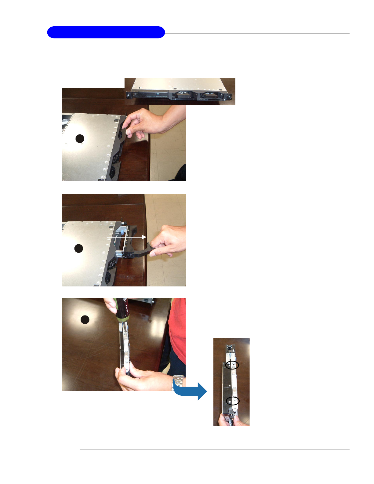
4-8
MS-9245 1U Rackmount Server
Serial ATA/SCSI Hard Disk Drives (Optional)
Unlock the HDD device holder and pull it
out from the chassis.
Screw the hard disk to the HDD device
holder.
3
2
1
Page 65
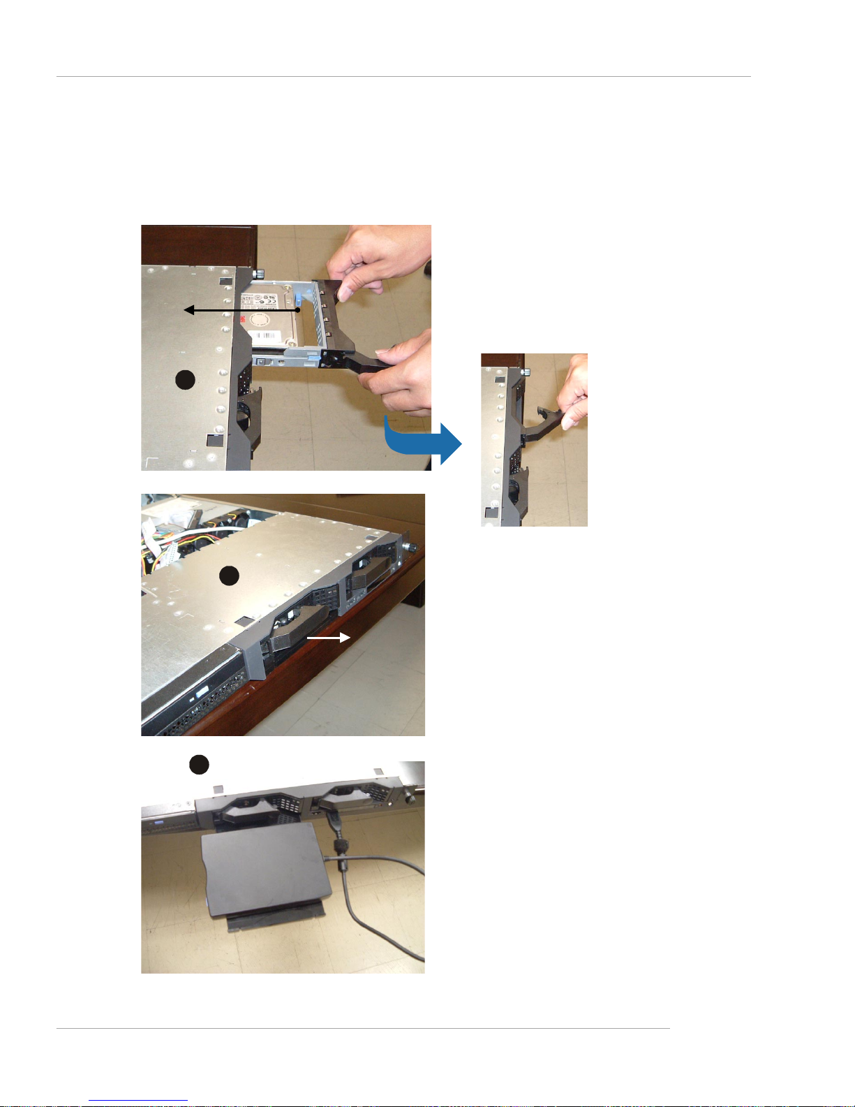
4-9
Chassis Installation
Slide the HDD device holder into the chassis and push it backward
until you hear a “click” sound to secure
the holder.
You may pull the USB tray open to rest
any USB device on it.
USB tray
4
5
6
Page 66
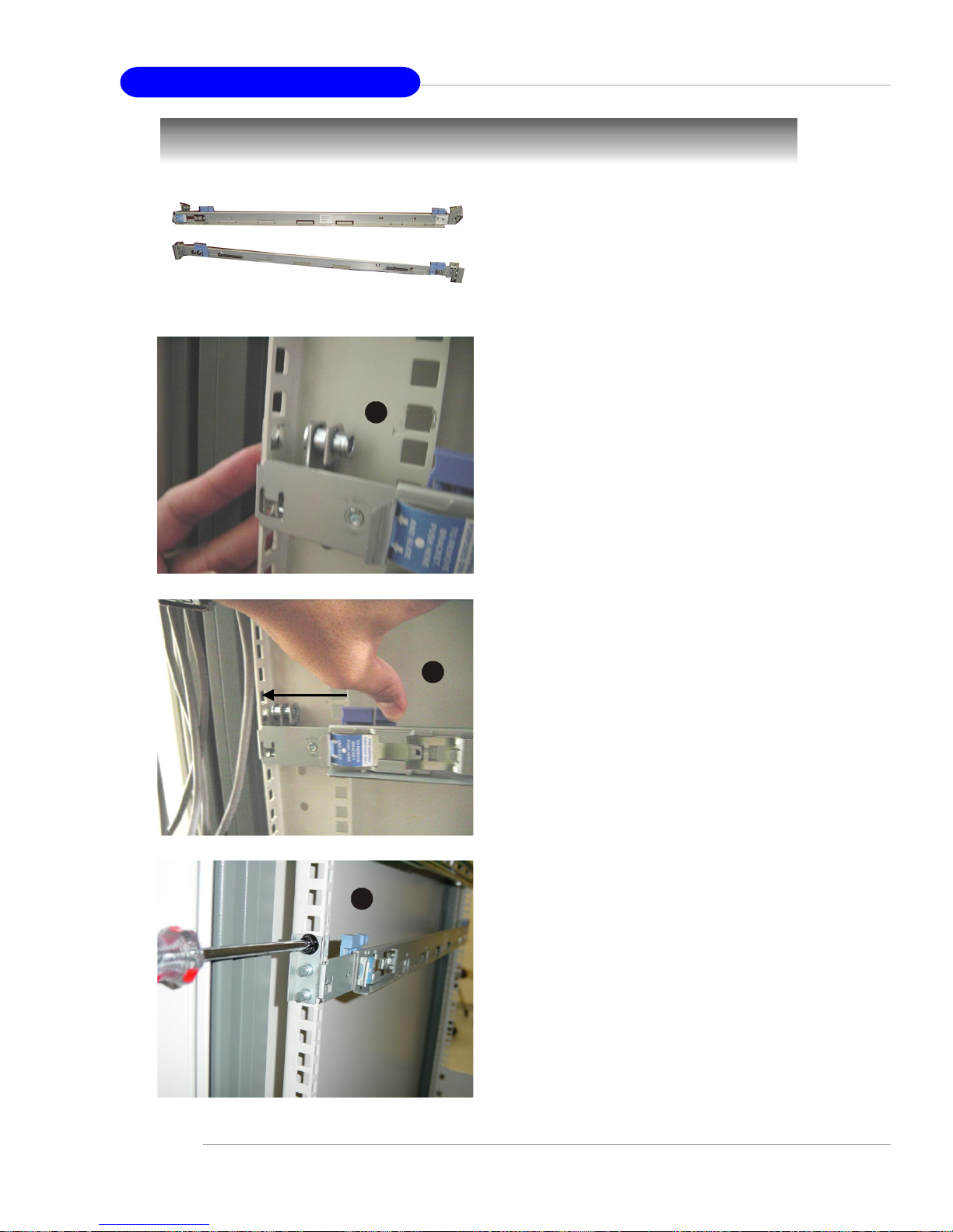
4-10
MS-9245 1U Rackmount Server
Rack Mounting
Take out the rail set for rack mounting.
rail set
Position the rail to the rack cabin.
Press the button to push the locking tab
forward. The rail will secure itself to the
cabin.
Screw to secure the rail on the rear.
Rear Right
1
2
3
Page 67
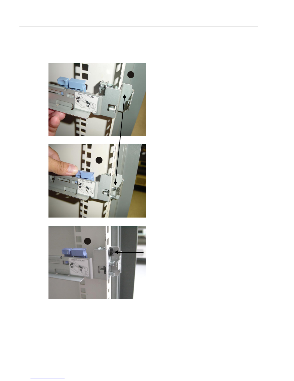
4-11
Chassis Installation
Position the rail to the rack cabin.
Press the button to push the locking tab
forward. The rail will secure itself to the
cabin.
Screw to secure the rail on the front.
Front Right
5
4
6
Page 68
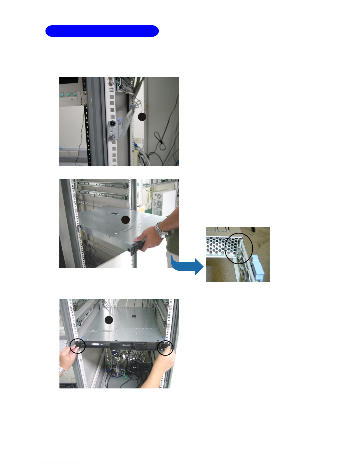
4-12
MS-9245 1U Rackmount Server
Follow the same procedures as mentioned earlier in this section to screw the
left rail on the front and rear.
Align the 1U rackmount server to the rails
and push it backward until it reaches the
end.
Screw the system to the cabin.
8
9
7
 Loading...