

Page 1
Copyright Notice
The material in this document is the intellectual property of MICRO-STAR
INTERNATIONAL. We take every care in the preparation of this document, but no
guarantee is given as to the correctness of its contents. Our products are under
continual improvement and we reserve the right to make changes without notice.
Trademarks
All trademarks in this manual are properties of their respective owners.
MSI® is registered trademark of Micro-Star Int’l Co.,Ltd.
■
NVIDIA® is registered trademark of NVIDIA Corporation.
■
ATI® is registered trademark of AMD Corporation.
■
AMD® is registered trademarks of AMD Corporation.
■
Intel® is registered trademarks of Intel Corporation.
■
Windows® is registered trademarks of Microsoft Corporation.
■
AMI® is registered trademark of American Megatrends Inc.
■
Award® is a registered trademark of Phoenix Technologies Ltd.
■
Sound Blaster® is registered trademark of Creative Technology Ltd.
■
Realtek® is registered trademark of Realtek Semiconductor Corporation.
■
JMicron® is registered trademark of JMicron Technology Corporation.
■
Netware® is registered trademark of Novell, Inc.
■
Lucid® is trademark of LucidLogix Technologies, Ltd.
■
VIA® is registered trademark of VIA Technologies, Inc.
■
ASMedia® is registered trademark of ASMedia Technology Inc.
■
iPad, iPhone, and iPod are trademarks of Apple Inc.
■
Qualcomm Atheros and Killer are trademarks of Qualcomm Atheros Inc.
■
Revision History
Revision Revision History Date
V.0
V. For J900I only 204/ 02
First release 203/
Preface
G52-7877X2
Page 2
Safety Instructions
Preface
Always read the safety instructions carefully.
■
Keep this User’s Manual for future reference.
■
Keep this equipment away from humidity.
■
Lay this equipment on a reliable at surface before setting it up.
■
The openings on the enclosure are for air convection hence protects the
■
equipment from overheating. DO NOT COVER THE OPENINGS.
Make sure the voltage of the power source is at 0/220V before connecting the
■
equipment to the power inlet.
Place the power cord such a way that people can not step on it. Do not place
■
anything over the power cord.
Always Unplug the Power Cord before inserting any add-on card or module.
■
All cautions and warnings on the equipment should be noted.
■
Never pour any liquid into the opening that can cause damage or cause electrical
■
shock.
If any of the following situations arises, get the equipment checked by service
■
personnel:
The power cord or plug is damaged.
◯
Liquid has penetrated into the equipment.
◯
The equipment has been exposed to moisture.
◯
The equipment does not work well or you can not get it work according to
◯
User’s Manual.
The equipment has been dropped and damaged.
◯
The equipment has obvious sign of breakage.
◯
DO NOT LEAVE THIS EQUIPMENT IN AN ENVIRONMENT ABOVE 60oC
■
(40oF), IT MAY DAMAGE THE EQUIPMENT.
Battery Information
European Union:
Batteries, battery packs, and accumulators should not be disposed
of as unsorted household waste. Please use the public collection
system to return, recycle, or treat them in compliance with the local
regulations.
Taiwan:
For better environmental protection, waste batteries should be
廢電池請回收
collected separately for recycling or special disposal.
California, USA:
The button cell battery may contain perchlorate material and requires
special handling when recycled or disposed of in California.
For further information please visit:
http://www.dtsc.ca.gov/hazardouswaste/perchlorate/
CAUTION: There is a risk of explosion, if battery is incorrectly replaced.
Replace only with the same or equivalent type recommended by the manufacturer.
2
Page 3
FCC-B Radio Frequency Interference Statement
This equipment has been tested and found to comply with the limits for a Class
B digital device, pursuant to Part 5 of the FCC Rules. These limits are designed
to provide reasonable protection against harmful interference in a residential
installation. This equipment generates, uses and can radiate radio frequency
energy and, if not installed and used in accordance with the instructions, may cause
harmful interference to radio communications. However, there is no guarantee that
interference will not occur in a particular installation. If this equipment does cause
harmful interference to radio or television reception, which can be determined
by turning the equipment o and on, the user is encouraged to try to correct the
interference by one or more of the measures listed below.
Reorient or relocate the receiving antenna.
◯
Increase the separation between the equipment and receiver.
◯
Connect the equipment into an outlet on a circuit dierent from that to which
◯
the receiver is connected.
Consult the dealer or an experienced radio/television technician for help.
◯
Notice
The changes or modications not expressly approved by the party responsible for
compliance could void the user’s authority to operate the equipment.
Notice 2
Shielded interface cables and A.C. power cord, if any, must be used in order to
comply with the emission limits.
VOIR LA NOTICE D’INSTALLATION AVANT DE RACCORDER AU RESEAU.
Micro-Star International
MS-7877
This device complies with Part 5 of the FCC Rules. Operation is subject to the
following two conditions:
this device may not cause harmful interference, and
)
this device must accept any interference received, including interference that
2)
may cause undesired operation.
Preface
CE Conformity
Hereby, Micro-Star International CO., LTD declares that this device is
in compliance with the essential safety requirements and other relevant
provisions set out in the European Directive.
3
Page 4
Radiation Exposure Statement
Preface
This equipment complies with FCC radiation exposure limits set forth for an
uncontrolled environment. This equipment and its antenna should be installed and
operated with minimum distance 20 cm between the radiator and your body. This
equipment and its antenna must not be co-located or operating in conjunction with
any other antenna or transmitter.
European Community Compliance Statement
The equipment complies with the RF Exposure Requirement 999/59/EC, Council
Recommendation of 2 July 999 on the limitation of exposure of the general public
to electromagnetic elds (0–300GHz). This wireless device complies with the R&TTE
Directive.
Taiwan Wireless Statements
無線設備警告聲明
經型式認證合格之低功率射頻電機,非經許可,公司、商號或使用者均不得擅自變更
頻率、加大功率或變更原設計之特性及功能。
低功率射頻電機之使用不得影響飛航安全及干擾合法通信;經發現有干擾現象時,應
立即停用,並改善至無干擾時方得繼續使用。前項合法通信,指依電信法規定作業之
無線電通信。低功率射頻電機須忍受合法通信或工業、科學及醫療用電波輻射性電機
設備之干擾。
警告使用者:這是甲類資訊產品,在居住的環境中使用時,可能會造成無線電干擾,在
這種情況下,使用者會被要求採取某些適當的對策。
Japan VCCI Class B Statement
クラス B 情報技術装置
この装置は、情報技術装置等電波障害自主規制協議会(VCCI)の基準に基づくクラ
スB情報技術装置です。この装置が家庭内でラジオやテレビジョン受信機に近接して
使われると、受信障害を引き起こすことがあります。取扱説明書にしたがって正し
い取り扱いをしてください。
Korea Warning Statements
당해 무선설비는 운용중 전파혼신 가능성이 있음
Chemical Substances Information
In compliance with chemical substances regulations, such as the EU REACH
Regulation (Regulation EC No. 907/2006 of the European Parliament and the
Council), MSI provides the information of chemical substances in products at:
http://www.msi.com/html/popup/csr/evmtprtt_pcm.html
4
Page 5
产品中有毒有害物质或元素名称及含量
根据中国<电子信息产品污染控制管理办法>
有毒有害物质或元素
部件名称
印刷电路板组件* ☓ 〇 〇 〇 〇 〇
电池**
外部信号连接头 ☓ 〇 〇 〇 〇 〇
线材 ☓ 〇 〇 〇 〇 〇
〇: 表示该有毒有害物质在该部件所有均质材料中的含量均在SJ/T363-2006标
准规定的限量要求下。
☓: 表示该有毒有害物质至少在该部件的某一均质材料中的含量超出SJ/T363-
2006标准规定的限量要求,但所有部件都符合欧盟RoHS要求。
* 印刷电路板组件: 包括印刷电路板及其构成的零部件。
** 电池本体上如有环保使用期限标识,以本体标识为主。
上述有毒有害物质或元素清单会依型号之部件差异而有所增减。
■
產品部件本体上如有环保使用期限标识,以本体标识为主。
■
铅
(Pb)汞(Hg)镉(Cd)
☓ 〇 〇 〇 〇 〇
六价铬
(Cr6+)
多溴联苯
(PBB)
多溴二苯醚
(PBDE)
Preface
5
Page 6
WEEE Statement
Preface
WEEE (Waste Electrical and Electronic Equipment)
ENGLISH
To protect the global environment and as an environmentalist, MSI must
remind you that...
Under the European Union (“EU”) Directive on Waste Electrical and
Electronic Equipment, Directive 2002/96/EC, which takes eect on August 3, 2005,
products of “electrical and electronic equipment” cannot be discarded as municipal
wastes anymore, and manufacturers of covered electronic equipment will be
obligated to take back such products at the end of their useful life. MSI will comply
with the product take back requirements at the end of life of MSI-branded products
that are sold into the EU. You can return these products to local collection points.
DEUTSCH
Hinweis von MSI zur Erhaltung und Schutz unserer Umwelt
Gemäß der Richtlinie 2002/96/EG über Elektro- und Elektronik-Altgeräte dürfen
Elektro- und Elektronik-Altgeräte nicht mehr als kommunale Abfälle entsorgt werden.
MSI hat europaweit verschiedene Sammel- und Recyclingunternehmen beauftragt,
die in die Europäische Union in Verkehr gebrachten Produkte, am Ende seines
Lebenszyklus zurückzunehmen. Bitte entsorgen Sie dieses Produkt zum gegebenen
Zeitpunkt ausschliesslich an einer lokalen Altgerätesammelstelle in Ihrer Nähe.
FRANÇAIS
En tant qu’écologiste et an de protéger l’environnement, MSI tient à rappeler ceci...
Au sujet de la directive européenne (EU) relative aux déchets des équipement
électriques et électroniques, directive 2002/96/EC, prenant eet le 3 août 2005,
que les produits électriques et électroniques ne peuvent être déposés dans les
décharges ou tout simplement mis à la poubelle. Les fabricants de ces équipements
seront obligés de récupérer certains produits en n de vie. MSI prendra en compte
cette exigence relative au retour des produits en n de vie au sein de la communauté
européenne. Par conséquent vous pouvez retourner localement ces matériels dans
les points de collecte.
РУССКИЙ
Компания MSI предпринимает активные действия по защите окружающей
среды, поэтому напоминаем вам, что....
В соответствии с директивой Европейского Союза (ЕС) по предотвращению
загрязнения окружающей среды использованным электрическим и электронным
оборудованием (директива WEEE 2002/96/EC), вступающей в силу 3
августа 2005 года, изделия, относящиеся к электрическому и электронному
оборудованию, не могут рассматриваться как бытовой мусор, поэтому
производители вышеперечисленного электронного оборудования обязаны
принимать его для переработки по окончании срока службы. MSI обязуется
соблюдать требования по приему продукции, проданной под маркой MSI на
территории EC, в переработку по окончании срока службы. Вы можете вернуть
эти изделия в специализированные пункты приема.
6
Page 7
ESPAÑOL
MSI como empresa comprometida con la protección del medio ambiente,
recomienda:
Bajo la directiva 2002/96/EC de la Unión Europea en materia de desechos y/o
equipos electrónicos, con fecha de rigor desde el 3 de agosto de 2005, los
productos clasicados como “eléctricos y equipos electrónicos” no pueden ser
depositados en los contenedores habituales de su municipio, los fabricantes de
equipos electrónicos, están obligados a hacerse cargo de dichos productos al
termino de su período de vida. MSI estará comprometido con los términos de
recogida de sus productos vendidos en la Unión Europea al nal de su periodo de
vida. Usted debe depositar estos productos en el punto limpio establecido por el
ayuntamiento de su localidad o entregar a una empresa autorizada para la recogida
de estos residuos.
NEDERLANDS
Om het milieu te beschermen, wil MSI u eraan herinneren dat….
De richtlijn van de Europese Unie (EU) met betrekking tot Vervuiling van Electrische
en Electronische producten (2002/96/EC), die op 3 Augustus 2005 in zal gaan
kunnen niet meer beschouwd worden als vervuiling. Fabrikanten van dit soort
producten worden verplicht om producten retour te nemen aan het eind van hun
levenscyclus. MSI zal overeenkomstig de richtlijn handelen voor de producten
die de merknaam MSI dragen en verkocht zijn in de EU. Deze goederen kunnen
geretourneerd worden op lokale inzamelingspunten.
SRPSKI
Da bi zaštitili prirodnu sredinu, i kao preduzeće koje vodi računa o okolini i prirodnoj
sredini, MSI mora da vas podesti da…
Po Direktivi Evropske unije (“EU”) o odbačenoj ekektronskoj i električnoj opremi,
Direktiva 2002/96/EC, koja stupa na snagu od 3. Avgusta 2005, proizvodi koji
spadaju pod “elektronsku i električnu opremu” ne mogu više biti odbačeni kao običan
otpad i proizvođači ove opreme biće prinuđeni da uzmu natrag ove proizvode na
kraju njihovog uobičajenog veka trajanja. MSI će poštovati zahtev o preuzimanju
ovakvih proizvoda kojima je istekao vek trajanja, koji imaju MSI oznaku i koji su
prodati u EU. Ove proizvode možete vratiti na lokalnim mestima za prikupljanje.
POLSKI
Aby chronić nasze środowisko naturalne oraz jako rma dbająca o ekologię, MSI
przypomina, że...
Zgodnie z Dyrektywą Unii Europejskiej (“UE”) dotyczącą odpadów produktów
elektrycznych i elektronicznych (Dyrektywa 2002/96/EC), która wchodzi w życie 3
sierpnia 2005, tzw. “produkty oraz wyposażenie elektryczne i elektroniczne “ nie
mogą być traktowane jako śmieci komunalne, tak więc producenci tych produktów
będą zobowiązani do odbierania ich w momencie gdy produkt jest wycofywany z
użycia. MSI wypełni wymagania UE, przyjmując produkty (sprzedawane na terenie
Unii Europejskiej) wycofywane z użycia. Produkty MSI będzie można zwracać w
wyznaczonych punktach zbiorczych.
Preface
7
Page 8

TÜRKÇE
Preface
Çevreci özelliğiyle bilinen MSI dünyada çevreyi korumak için hatırlatır:
Avrupa Birliği (AB) Kararnamesi Elektrik ve Elektronik Malzeme Atığı, 2002/96/EC
Kararnamesi altında 3 Ağustos 2005 tarihinden itibaren geçerli olmak üzere,
elektrikli ve elektronik malzemeler diğer atıklar gibi çöpe atılamayacak ve bu
elektonik cihazların üreticileri, cihazların kullanım süreleri bittikten sonra ürünleri geri
toplamakla yükümlü olacaktır. Avrupa Birliği’ne satılan MSI markalı ürünlerin kullanım
süreleri bittiğinde MSI ürünlerin geri alınması isteği ile işbirliği içerisinde olacaktır.
Ürünlerinizi yerel toplama noktalarına bırakabilirsiniz.
ČESKY
Záleží nám na ochraně životního prostředí - společnost MSI upozorňuje...
Podle směrnice Evropské unie (“EU”) o likvidaci elektrických a elektronických
výrobků 2002/96/EC platné od 3. srpna 2005 je zakázáno likvidovat “elektrické
a elektronické výrobky” v běžném komunálním odpadu a výrobci elektronických
výrobků, na které se tato směrnice vztahuje, budou povinni odebírat takové výrobky
zpět po skončení jejich životnosti. Společnost MSI splní požadavky na odebírání
výrobků značky MSI, prodávaných v zemích EU, po skončení jejich životnosti. Tyto
výrobky můžete odevzdat v místních sběrnách.
MAGYAR
Annak érdekében, hogy környezetünket megvédjük, illetve környezetvédőként
fellépve az MSI emlékezteti Önt, hogy ...
Az Európai Unió („EU”) 2005. augusztus 3-án hatályba lépő, az elektromos
és elektronikus berendezések hulladékairól szóló 2002/96/EK irányelve szerint
az elektromos és elektronikus berendezések többé nem kezelhetőek lakossági
hulladékként, és az ilyen elektronikus berendezések gyártói kötelessé válnak az
ilyen termékek visszavételére azok hasznos élettartama végén. Az MSI betartja
a termékvisszavétellel kapcsolatos követelményeket az MSI márkanév alatt az
EU-n belül értékesített termékek esetében, azok élettartamának végén. Az ilyen
termékeket a legközelebbi gyűjtőhelyre viheti.
ITALIANO
Per proteggere l’ambiente, MSI, da sempre amica della natura, ti ricorda che….
In base alla Direttiva dell’Unione Europea (EU) sullo Smaltimento dei Materiali
Elettrici ed Elettronici, Direttiva 2002/96/EC in vigore dal 3 Agosto 2005, prodotti
appartenenti alla categoria dei Materiali Elettrici ed Elettronici non possono più
essere eliminati come riuti municipali: i produttori di detti materiali saranno obbligati
a ritirare ogni prodotto alla ne del suo ciclo di vita. MSI si adeguerà a tale Direttiva
ritirando tutti i prodotti marchiati MSI che sono stati venduti all’interno dell’Unione
Europea alla ne del loro ciclo di vita. È possibile portare i prodotti nel più vicino
punto di raccolta
8
Page 9

Contents
English ......................................................................................
Motherboard Specications ....................................................................................2
Back Panel ..............................................................................................................4
Memory Installation .................................................................................................5
Internal Connectors.................................................................................................6
BIOS Setup .............................................................................................................22
한국어 .......................................................................................25
메인보드 사양 .........................................................................................................26
후면 패널 .................................................................................................................28
메모리 설치 .............................................................................................................29
내장 커넥터 .............................................................................................................30
BIOS 설정 ...............................................................................................................36
Français ....................................................................................39
Spécications ..........................................................................................................40
Panneau Arrière ......................................................................................................42
Installation de mémoire ...........................................................................................43
Connecteurs d’alimentation ....................................................................................44
Conguration BIOS .................................................................................................50
Deutsch ....................................................................................53
Spezikationen........................................................................................................54
Rücktafel-Übersicht.................................................................................................56
Speicher ..................................................................................................................57
Interne Anschlüsse .................................................................................................58
BIOS Setup .............................................................................................................64
Русский ....................................................................................67
Характеристики материнской платы....................................................................68
Задняя панель .......................................................................................................70
Установка памяти ..................................................................................................7
Внутренние разъемы ............................................................................................72
Настройка BIOS .....................................................................................................78
Preface
9
Page 10

简体中文 ...................................................................................8
主板规格 ..................................................................................................................82
Preface
后置面板 ..................................................................................................................84
内存安装 ..................................................................................................................85
内部接口 ..................................................................................................................86
BIOS Setup .............................................................................................................92
繁體中文 ...................................................................................95
規格 .........................................................................................................................96
背板快速指南 ..........................................................................................................98
安裝記憶體 ..............................................................................................................99
內建接頭 ................................................................................................................00
BIOS 設定 .............................................................................................................06
日本語 .....................................................................................09
マザーボードの仕様 ..............................................................................................0
I/Oパネル ..............................................................................................................2
メモリの装着 ........................................................................................................3
内部コネクター .....................................................................................................4
BIOSの設定 ...........................................................................................................20
0
Page 11
English
Top: V GA P ort
Bot tom: DVI-D
SATA1 SATA2
T:
M:
B:
Lin e-In
Lin e-Ou t
Mic
USB3 .0 port
HDMI port
JPW R2
JTP M1
JPW R1
JBAT1 JCI 1
JAU D1
PCI _E1
JUS B1
JFP 1 JCO M1
CPU FAN
SYS FAN1
DIM M1
DIM M2
Top: L AN Jack
Bot tom: USB 2 .0 p ort s
Top : mouse
Bot tom: keybo ard
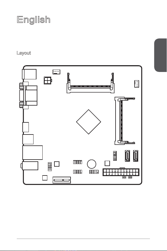
Thank you for choosing the J900I Series (MS-7877 v.X) Mini-ITX motherboards.
The J900I Series motherboard is design based on Intel® Celeron J900 processor.
The J900I Series motherboards deliver a high performance and energy saving
solution for BOX PC.
Layout
English
Page 12
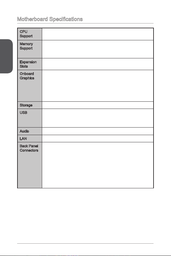
Motherboard Specications
CPU
Support
Memory
English
Support
Expansion
Slots
Onboard
Graphics
Storage 2x SATA 3Gb/s ports■
USB x USB 3.0 port on the back panel
Audio Realtek® ALC887 Codec■
LAN Realtek® RTL8G Gigabit LAN controller■
Back Panel
Connectors
Intel® Celeron J900 processor■
2x DDR3 SO-DIMM memory slots supporting up to 8GB
■
Supports DDR3 333/ 066 MHz
■
Dual channel memory architecture
■
x PCIe 2.0 x slot■
x DVI-D port, supports the maximum resolution of 2560x600
■
@ 60Hz, 24bpp
x VGA port, supporting a maximum resolution of
■
@ 60Hz, 24bpp
x HDMI port, supporting a maximum resolution of 920x200
■
@ 60Hz, 24bpp
■
4x USB 2.0 ports (2 ports on the back panel, 2 ports available
■
through an onboard USB 2.0 connector)
x PS/2 keyboard port
■
x PS/2 mouse port
■
x VGA port
■
x DVI-D port
■
x HDMI port
■
x USB 3.0 port
■
x LAN (RJ45) port
■
2x USB 2.0 ports
■
3x audio jacks
■
2560x600
2
Page 13
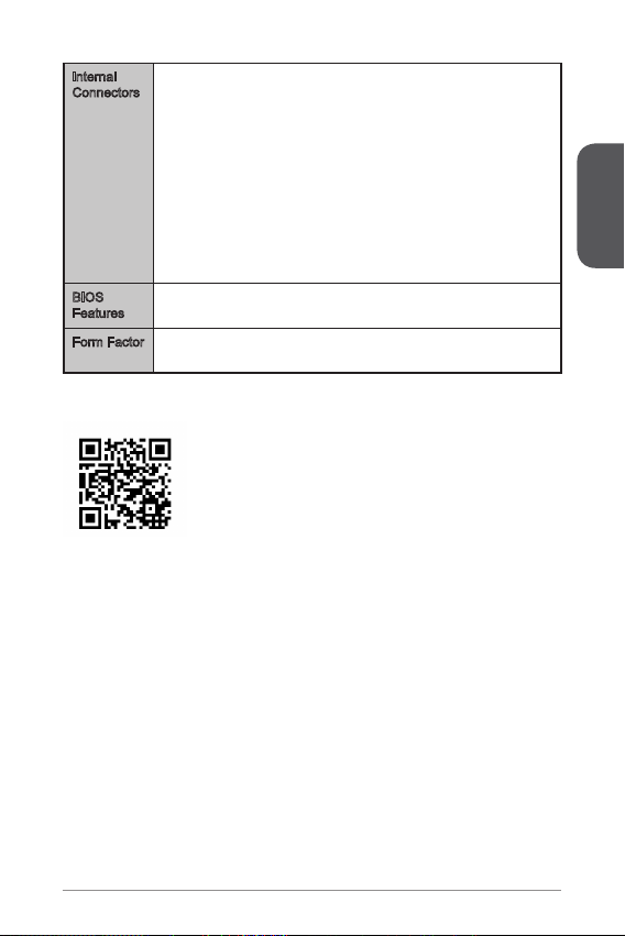
Internal
Connectors
BIOS
Features
Form Factor Mini-ITX Form Factor
x 24-pin ATX main power connector
■
x 4-pin ATX 2V power connector
■
2x SATA 3Gb/s connectors
■
x USB 2.0 connector (supports additional 2 USB 2.0 ports)
■
x 4-pin CPU fan connectors
■
x 4-pin system fan connector
■
x Front panel audio connector
■
x Serial port connector
■
x TPM connector
■
x System panel connector
■
x Chassis Intrusion connector
■
x Clear CMOS jumper
■
■
x 64 Mb ash
UEFI AMI BIOS
■
■
6.7 in. x 6.7 in. (7.0 cm x 7.0 cm)
■
For more information on compatible components, please
visit http://www.msi.com/service/test-report/
English
3
Page 14
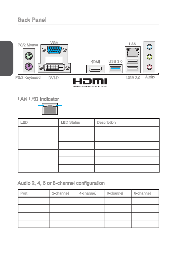
Back Panel
®
English
PS/2 Keyboard
PS/2 Mouse
VGA
DVI-D
HDMI
USB 3.0
LAN LED Indicator
LINK/ACT
LED
LED LED Status Description
Link/ Activity LED
Speed LED
SPEED
LED
O No link
Yellow Linked
Blinking Data activity
O 0 Mbps connection
Green 00 Mbps connection
Orange Gbps connection
Audio 2, 4, 6 or 8-channel conguration
Port 2-channel 4-channel 6-channel 8-channel
Blue Line in RS-Out RS-Out RS-Out
Green Line out FS-Out FS-Out FS-Out
Pink Mic Mic CS-Out CS-Out
Front audio - - - SS-Out
LAN
USB 2.0
Audio
4
Page 15
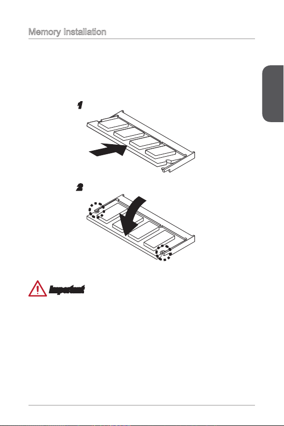
Memory Installation
The SO-DIMM slot is intended for memory modules.
Locate the SO-DIMM slot. Align the notch on the DIMM with the key on the slot
.
and insert the DIMM into the slot.
Push the DIMM gently downwards until the slot levers click and lock the DIMM
2.
in place.
2
Important
You can barely see the golden nger if the DIMM is properly inserted in the DIMM
•
slot.
To uninstall the DIMM, ip the slot levers outwards and the DIMM will be released
•
instantly.
English
5
Page 16
Internal Connectors
4.+ 12V
2
.Gr oun d
3.+ 12V
1
.Gr oun d
13. +3. 3
V
1.+ 3.3
V
14. -12 V
2.+ 3.3
V
15. Gro und
3
.Gr oun d
16. PS- ON
#
4.+ 5
V
17. Gro und
5
.Gr oun d
18. Gro und
6.+ 5
V
19. Gro und
7
.Gr oun d
22. +5
V
10. +12 V
20. Res
8.P W
R O
K
23. +5
V
11.+ 12V
21. +5
V
9.5 VSB
24. Gro und
12. +3. 3
V
1
.
D
C
D
3
.
S
O
U
T
1
0
.
N
o
P
i
n
5
.
G
r
o
u
n
d
7
.
R
T
S
9
.
R
I
8
.
C
T
S
6
.
D
S
R
4
.
D
T
R
2
.
S
I
N
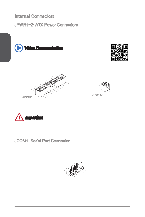
JPWR~2: ATX Power Connectors
These connectors allow you to connect an ATX power supply. To connect the ATX
power supply, align the power supply cable with the connector and rmly press the
cable into the connector. If done correctly, the clip on the power cable should be
English
hooked on the motherboard’s power connector.
Video Demonstration
Watch the video to learn how to install power supply connectors.
http://youtu.be/gkDYyR_83I4
JPWR
JPWR2
Important
Make sure that all the power cables are securely connected to a proper ATX power
supply to ensure stable operation of the motherboard.
JCOM: Serial Port Connector
This connector is a 6550A high speed communication port that sends/receives 6
bytes FIFOs. You can attach a serial device.
6
Page 17
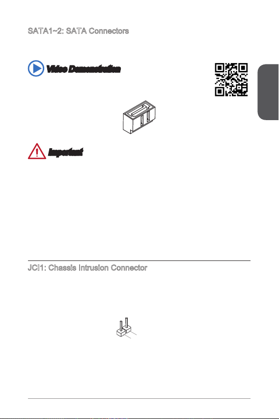
SATA~2: SATA Connectors
2
.
C
I
N
T
R
U
1
.
G
r
o
u
n
d
This connector is a high-speed SATA interface port. Each connector can connect to
one SATA device. SATA devices include disk drives (HDD), solid state drives (SSD),
and optical drives (CD/ DVD/ Blu-Ray).
Video Demonstration
Watch the video to learn how to Install SATA HDD.
http://youtu.be/RZsMpqxythc
Important
Many SATA devices also need a power cable from the power supply. Such devices
•
include disk drives (HDD), solid state drives (SSD), and optical drives (CD / DVD /
Blu-Ray). Please refer to the device’s manual for further information.
Many computer cases also require that large SATA devices, such as HDDs, SSDs,
•
and optical drives, be screwed down into the case. Refer to the manual that came
with your computer case or your SATA device for further installation instructions.
Please do not fold the SATA cable at a 90-degree angle. Data loss may result
•
during transmission otherwise.
SATA cables have identical plugs on either sides of the cable. However, it is
•
recommended that the at connector be connected to the motherboard for space
saving purposes.
JCI: Chassis Intrusion Connector
This connector connects to the chassis intrusion switch cable. If the computer case
is opened, the chassis intrusion mechanism will be activated. The system will record
this intrusion and a warning message will ash on screen. To clear the warning, you
must enter the BIOS utility and clear the record.
English
7
Page 18
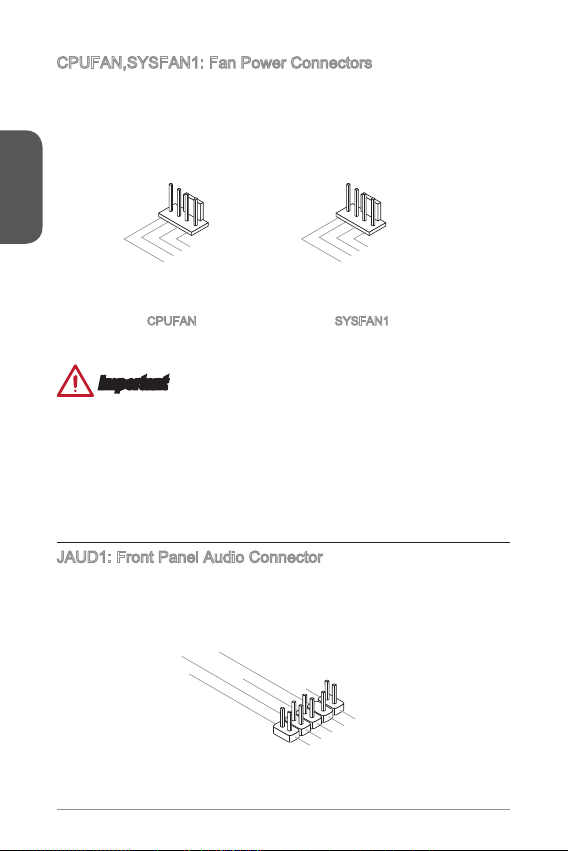
CPUFAN,SYSFAN: Fan Power Connectors
1.G ro und
2.+ 12 V
3.S en s
e
4.S pe ed
C
ont ro
l
1.G ro und
2.S pe ed
C
ont ro
l
3.S en s
e
4.N C
1.M I
C L
3.M IC R
10. He ad
P
hon e
Det ec ti on
5.H ea d
P
hon e
R
7.S EN SE _SE N
D
9.H ea d
P
hon e
L
8.N o
Pi
n
6.M I
C D
ete ct io n
4.N C
2
.Gr ou nd
The fan power connectors support system cooling fans with +2V. If the motherboard
has a System Hardware Monitor chipset on-board, you must use a specially designed
fan with a speed sensor to take advantage of the CPU fan control. Remember to
connect all system fans. Some system fans may not connect to the motherboard and
will instead connect to the power supply directly. A system fan can be plugged into
any available system fan connector.
English
CPUFAN
SYSFAN
Important
Please refer to your processor’s ocial website or consult your vendor to nd
•
recommended CPU heatsink.
These connectors support Smart Fan Control with liner mode. The Command
•
Center utility can be installed to automatically control the fan speeds according to
the CPU’s and system’s temperature.
If there are not enough ports on the motherboard to connect all system fans,
•
adapters are available to connect a fan directly to a power supply.
Before rst boot up, ensure that there are no cables impeding any fan blades.
•
JAUD: Front Panel Audio Connector
This connector allows you to connect the front audio panel located on your computer
case. This connector is compliant with the Intel® Front Panel I/O Connectivity Design
Guide.
8
Page 19
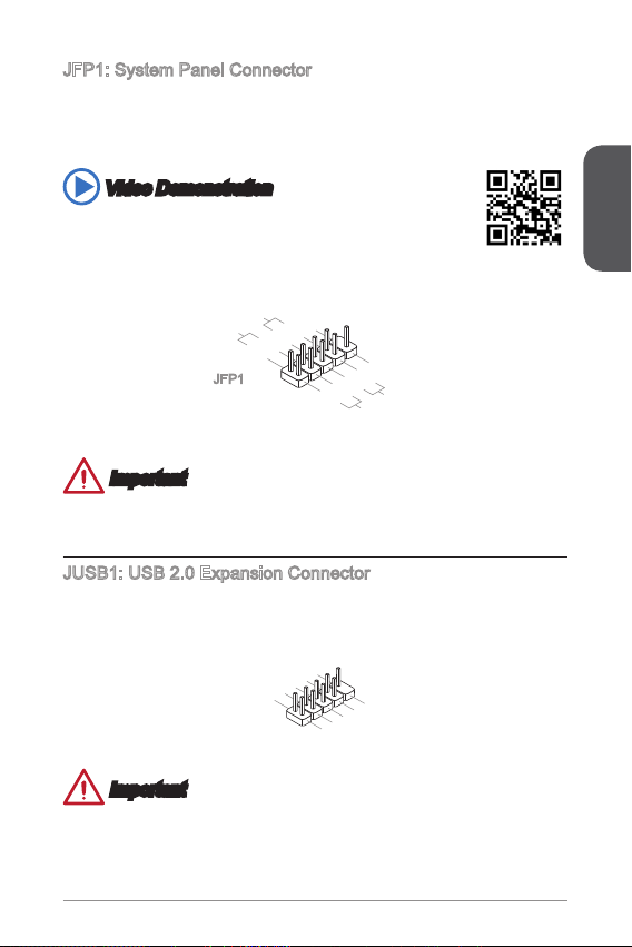
JFP: System Panel Connector
1.
+
3.
-
10. No
Pi
n
5.
Res et
S
wit ch
HDD
LE
D
P
owe r
Swi tc h
P
owe r
LE
D
7.
+
9.R es erv e
d
8.
-
6.
+
4.-
2.+
1
.
V
C
C
3
.
U
S
B
0
-
1
0
.
NC
5
.
U
S
B
0
+
7
.
G
r
o
u
n
d
9
.
N
o
P
i
n
8
.
G
r
o
u
n
d
6
.
U
S
B
1
+
4
.
U
S
B
1
-
2
.
V
C
C
These connectors connect to the front panel switches and LEDs. The JFP
connector is compliant with the Intel® Front Panel I/O Connectivity Design Guide.
When installing the front panel connectors, please use the optional M-Connector to
simplify installation. Plug all the wires from the computer case into the M-Connector
and then plug the M-Connector into the motherboard.
Video Demonstration
Watch the video to learn how to Install front panel connectors.
http://youtu.be/DPELIdVNZUI
JFP
Important
On the connectors coming from the case, pins marked by small triangles are positive
wires. Please use the diagrams above and the writing on the optional M-Connectors
to determine correct connector orientation and placement.
JUSB: USB 2.0 Expansion Connector
This connector is designed for connecting high-speed USB peripherals such as USB
HDDs, digital cameras, MP3 players, printers, modems, and many others.
English
Important
Note that the VCC and GND pins must be connected correctly to avoid possible
damage.
9
Page 20
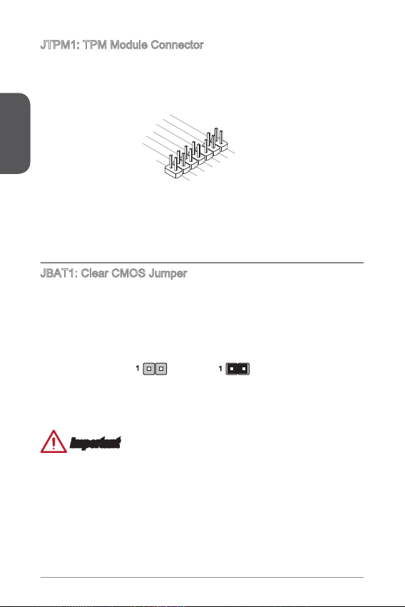
JTPM: TPM Module Connector
10. No
Pi
n
14. Groun d
8.5 V
P
owe r
12. Groun d
6.S erial
IR
Q
4.3 .3V
P
owe r
2.3 V
Sta ndby
p
owe r
1.L P
C C
loc
k
3.L P
C
Res e
t
5.L P
C a
ddr es
s &
dat a
pin 0
7.L P
C a
ddr es
s &
dat a
p
in1
9.L P
C a
ddr es
s &
dat a
pin 2
11
.LP C
a
ddr es
s &
dat a
p
in3
13. LP
C
Fra m
e
This connector connects to a TPM (Trusted Platform Module). Please refer to the
TPM security platform manual for more details and usages.
English
JBAT: Clear CMOS Jumper
There is CMOS RAM onboard that is external powered from a battery located on the
motherboard to save system conguration data. With the CMOS RAM, the system
can automatically boot into the operating system (OS) every time it is turned on. If
you want to clear the system conguration, set the jumpers to clear the CMOS RAM.
Keep Data Clear Data
Important
You can clear the CMOS RAM by shorting this jumper while the system is o.
Afterwards, open the jumper . Do not clear the CMOS RAM while the system is on
because it will damage the motherboard.
20
Page 21
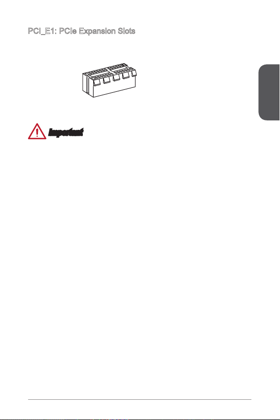
PCI_E: PCIe Expansion Slots
The PCIe slot supports the PCIe interface expansion card.
PCIe x Slot
Important
When adding or removing expansion cards, always turn o the power supply and
unplug the power supply power cable from the power outlet. Read the expansion
card’s documentation to check for any necessary additional hardware or software
changes.
English
2
Page 22
BIOS Setup
The default settings oer the optimal performance for system stability in normal
conditions. You may need to run the Setup program when:
An error message appears on the screen during the system booting up, and
■
requests you to run SETUP.
English
You want to change the default settings for customized features.
■
Important
Please load the default settings to restore the optimal system performance and
•
stability if the system becomes unstable after changing BIOS settings. Select the
"Restore Defaults" and press <Enter> in BIOS to load the default settings.
If you are unfamiliar with the BIOS settings, we recommend that you keep the
•
default settings to avoid possible system damage or failure booting due to
inappropriate BIOS conguration.
Entering BIOS Setup
Power on the computer and the system will start the Power On Self Test (POST)
process. When the message below appears on the screen, please <DEL> key to
enter BIOS:
Press DEL key to enter Setup Menu, F to enter Boot Menu
If the message disappears before you respond and you still need to enter BIOS,
restart the system by turning the computer OFF then back ON or pressing the
RESET button. You may also restart the system by simultaneously pressing <Ctrl>,
<Alt>, and <Delete> keys.
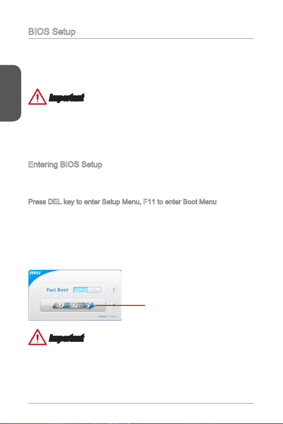
MSI additionally provides a method to enter the BIOS setup. You can click the
“GO2BIOS” tab on “MSI Fast Boot” utility screen to enable the system going to BIOS
setup directly at next boot.
Click "GO2BIOS" tab on "MSI Fast
Boot" utility screen.
Important
Please be sure to install the “MSI Fast Boot” utility before using it to enter the BIOS
setup.
22
Page 23
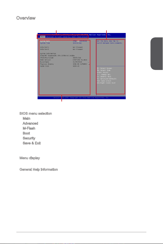
Overview
After entering BIOS, the following screen is displayed.
BIOS menu selection
▶
Menu display
▶
This area provides BIOS settings and information to be congured.
General Help information
▶
The General Help displays a brief description to assist you in understanding the
selected item.
BIOS menu selection
Menu display
Main - Use this menu for basic system congurations, such as time, date etc.
Advanced - Use this menu to set up the items of special enhanced features.
M-Flash - This menu provides the way to update BIOS with a USB ash disk.
Boot - Use this menu to specify the priority of boot devices.
Security - Use this menu to set supervisor and user passwords.
Save & Exit - This menu allows you to load the BIOS default values or factory
default settings into the BIOS and exit the BIOS setup utility with or without
changes.
General Help information
English
23
Page 24

English
24
Page 25
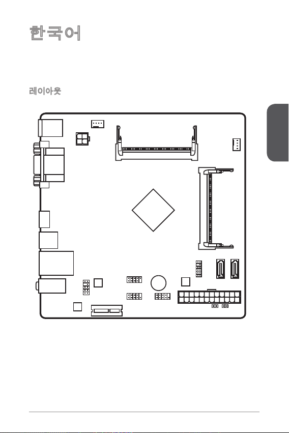
한국어
Top: V GA P ort
Bot tom: DVI-D
SATA1 SATA2
T:
M:
B:
Lin e-In
Lin e-Ou t
Mic
USB3 .0 port
HDMI port
JPW R2
JTP M1
JPW R1
JBAT1 JCI 1
JAU D1
PCI _E1
JUS B1
JFP 1 JCO M1
CPU FAN
SYS FAN1
DIM M1
DIM M2
Top: L AN Jack
Bot tom: USB 2 .0 p ort s
Top : mouse
Bot tom: keybo ard
J900I 시리즈 (MS-7877 v.X) Mini-ITX 메인보드를 선택해 주셔서 감사합니다.
J900I 시리즈 메인보드는 최적의 시스템 효율을 위해 Intel® Celeron J900 프로세서
에 기반을 둔 제품입니다. J900I 시리즈 메인보드는 BOX PC에 고성능과 절전 솔루
션을 제공합니다.
레이아웃
한국어
25
Page 26
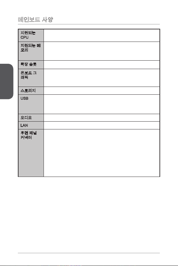
메인보드 사양
지원되는
CPU
지원되는 메모리DDR3 SO-DIMM 메모리 슬롯 2개, 최대 8GB 지원
확장 슬롯 PCIe 2.0 x 슬롯 개■
한국어
온보드 그
래픽
스토리지 SATA 3Gb/s 포트 2개■
USB 후면 패널에 USB 3.0 포트
오디오 Realtek® ALC887 코덱■
LAN Realtek® RTL8G Gigabit LAN 컨트롤러■
후면 패널
커넥터
Intel® Celeron J900 프로세서 ■
■
DDR3 333/ 066 MHz 지원
■
듀얼 채널 메모리 지원
■
DVI-D 포트 개, 최대 2560x600 @ 60Hz, 24bpp 해상도 지원
■
VGA 포트 개, 최대
■
HDMI 포트 개, 최대 920x200 @ 60Hz, 24bpp 해상도 지원
■
■
USB 2.0 포트 4개 (후면 패널에 2포트, 내부 USB 2.0 커넥터를
■
통해 2포트 사용)
PS/2 키보드 포트 개
■
PS/2 마우스 포트 개
■
VGA 포트 개
■
DVI-D 포트 개
■
HDMI 포트 개
■
USB 3.0 포트 개
■
LAN (RJ45) 포트 개
■
USB 2.0 포트 2개
■
오디오 잭 3개
■
2560x600 @ 60Hz, 24bpp 해상도 지원
26
Page 27
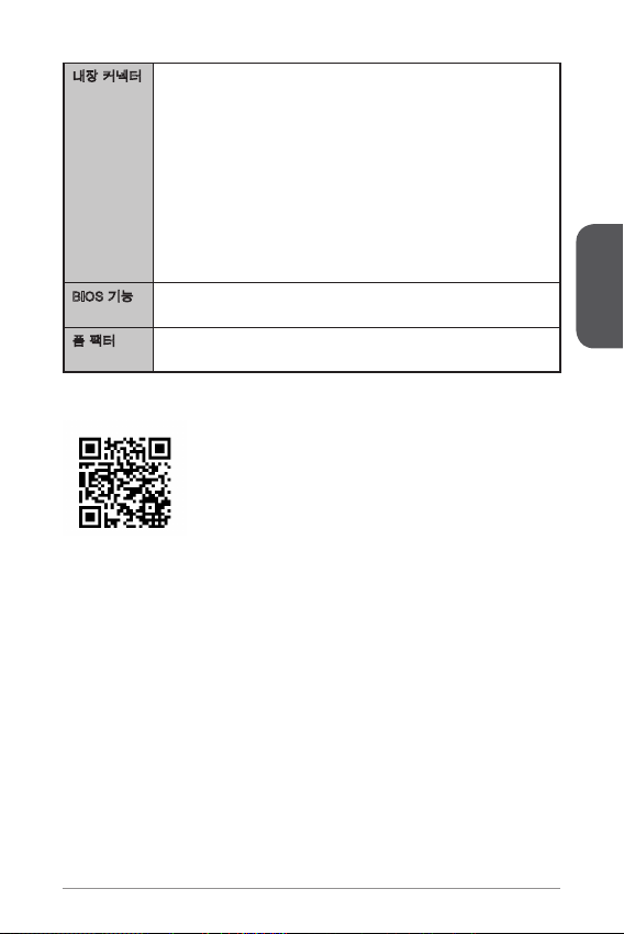
내장 커넥터 24 핀 ATX 메인 전원 커넥터 개
BIOS 기능 64 Mb 플래시 개
폼 팩터 Mini-ITX 폼 팩터
■
4 핀 ATX 2V 전원 커넥터 개
■
SATA 3Gb/s 커넥터 2개
■
USB 2.0 커넥터 개 (외 USB 2.0 2포트 지원)
■
4 핀 CPU 팬 커넥터 개
■
4 핀 시스템 팬 커넥터 개
■
전면 패널 오디오 커넥터 개
■
시리얼 포트 커넥터 개
■
TPM 커넥터 개
■
시스템 패널 커넥터 2개
■
섀시 침입 커넥터 개
■
CMOS 클리어 점퍼 개
■
■
UEFI AMI BIOS
■
■
6.7 in. x 6.7 in. (7.0 cm x 7.0 cm)
■
호환 가능한 부품에 대한 자세한 정보는
http://www.msi.com/service/test-report/를 참조하세요.
한국어
27
Page 28
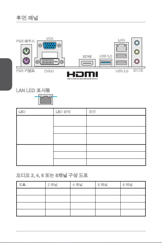
후면 패널
®
VGA
DVI-D
HDMI
USB 3.0
한국어
PS/2 마우스
PS/2 키보드
LAN LED 표시등
LINK/ACT
LED
LED LED 상태 조건
Link/ Activity LED
(링크/ 통신 LED)
Speed LED
(속도 LED)
SPEED
LED
꺼짐
노란색 LAN이 올바르게 연결되었습니다.
깜빡임
꺼짐 0 Mbps 속도로 연결되었습니다.
녹색 00 Mbps 속도로 연결되었습니다.
오렌지색 Gbps 속도로 연결되었습니다.
LAN이 올바르게 연결되지 않았
습니다.
컴퓨터가 LAN으로 정상적인 통신
중입니다.
오디오 2, 4, 6 또는 8채널 구성 도표
포트 2 채널 4 채널 6 채널 8 채널
파란색 라인 입력 RS 출력 RS 출력 RS 출력
회색 라인 출력 FS 출력 FS 출력 FS 출력
핑크색 마이크 마이크 CS 출력 CS 출력
전면 오디오 - - - SS 출력
LAN
USB 2.0
오디오
28
Page 29
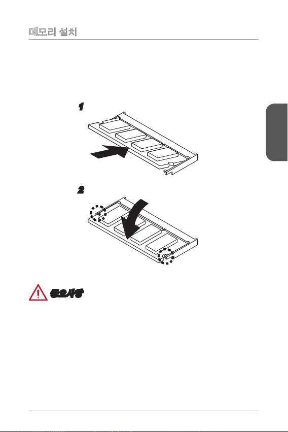
메모리 설치
SO-DIMM 슬롯은 메모리 모듈 용입니다.
DIMM의 홈을 SO-DIMM 슬롯의 키에 맞춘 후, 아래로 삽입합니다.
.
슬롯 레버가 닫히고 DIMM이 올바로 고정될 때까지 계속하여 DIMM을 아래로 조
2.
심스럽게 밀어주세요.
2
중요사항
DIMM이 슬롯에 제대로 삽입되었다면 골든 핑거가 보이지 않습니다.
•
슬롯 레버를 밖으로 당겨.DIMM을 제거할 수 있습니다.
•
한국어
29
Page 30
내장 커넥터
4.+ 12V
2
.Gr oun d
3.+ 12V
1
.Gr oun d
13. +3. 3
V
1.+ 3.3
V
14. -12 V
2.+ 3.3
V
15. Gro und
3
.Gr oun d
16. PS- ON
#
4.+ 5
V
17. Gro und
5
.Gr oun d
18. Gro und
6.+ 5
V
19. Gro und
7
.Gr oun d
22. +5
V
10. +12 V
20. Res
8.P W
R O
K
23. +5
V
11.+ 12V
21. +5
V
9.5 VSB
24. Gro und
12. +3. 3
V
1
.
D
C
D
3
.
S
O
U
T
1
0
.
N
o
P
i
n
5
.
G
r
o
u
n
d
7
.
R
T
S
9
.
R
I
8
.
C
T
S
6
.
D
S
R
4
.
D
T
R
2
.
S
I
N
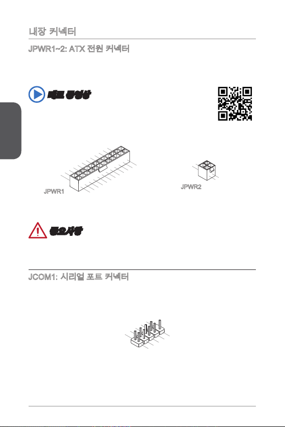
JPWR~2: ATX 전원 커넥터
이 커넥터를 사용하여 ATX 전원 공급 장치를 연결할 수 있습니다. ATX 전원 공급 장
치를 연결하려면 커넥터에 전원 공급 케이블을 정렬하고 케이블을 커넥터 안쪽으로 꼭
눌러줍니다. 만약 정확하게 장착하였다면 전원 케이블의 클립이 메인보드의 전원 커넥
터에 꼭 맞게 걸리게 됩니다.
데모 동영상
전원 공급 장치 커넥터 설치에 대한 동영상을 참조하려면 아래의 웹사
이트를 방문하세요.
한국어
http://youtu.be/gkDYyR_83I4
JPWR
JPWR2
중요사항
모든 전원 케이블이 ATX 전원 공급 장치에 올바르게 연결되어 메인보드가 안정적으로
작동하는지 확인하세요.
JCOM: 시리얼 포트 커넥터
이 커넥터는 6550A 고속 통신 포트로서 6바이트의 FIFO를 송수신합니다. 시리얼
장치를 연결할 수 있습니다.
30
Page 31

SATA~2: SATA 커넥터
2
.
C
I
N
T
R
U
1
.
G
r
o
u
n
d
이 커넥터는 고속 SATA 인터페이스 포트에 사용됩니다.각 커넥터는 하나의 SATA 장
치에 연결할수 있습니다. SATA 장치는 디스크 드라이브(HDD), 솔리드 스테이트 드라
이브(SSD)및 옵티컬 드라이브 (CD/ DVD/ 블루 레이)를 포함합니다.
데모 동영상
SATA HDD 설치에 대한 동영상을 참조하려면 아래의 웹사이트를 방
문하세요.
http://youtu.be/RZsMpqxythc
중요사항
디스크 드라이브 (HDD),솔리드 스테이트 드라이브 (SSD) 및 옵티컬 드라이브 (CD /
•
DVD / 블루 레이) 와 같은 다수의 SATA 장치는 전원 공급 장치에 연결된 전원 케이
블도 필요합니다. 자세한 내용은 해당 기기 메뉴얼을 참조하세요.
다수의 컴퓨터 케이스는 HDD, SSD, 옵티컬 드라이브와 같은 대형 SATA 장치가 케
•
이스 안쪽 하단에 고정되어 있도록 요구합니다.설치에 대한 자세한 설명은 컴퓨터
케이스나 SATA 장치와 함께 제공되는 메뉴얼을 참조하세요.
SATA 케이블을 90도로 꺽지 마세요. 그럴 경우 전송 중 데이터가 손상될 수 있습
•
니다.
SATA 케이블의 양쪽 모두에 동일한 플러그가 있지만 공간 절약을 위해 플랫 커넥터
•
를 메인보드에 연결할것을 권장합니다.
JCI: 섀시 침입 커넥터
이 커넥터는 섀시 침입 스위치 케이블에 연결됩니다. 컴퓨터 케이스가 열리는 경우, 섀
시 침입 메커니즘이 활성화됩니다. 시스템이 이 상태를 기록하고 화면에 경고 메시지
가 나타납니다. 경고를 지우려면, BIOS 유틸리티에서 레코드를 지워야 합니다.
한국어
3
Page 32

CPUFAN,SYSFAN: 팬 전원 커넥터
1.G ro und
2.+ 12 V
3.S en s
e
4.S pe ed
C
ont ro
l
1.G ro und
2.S pe ed
C
ont ro
l
3.S en s
e
4.N C
1.M I
C L
3.M IC R
10. He ad
P
hon e
Det ec ti on
5.H ea d
P
hon e
R
7.S EN SE _SE N
D
9.H ea d
P
hon e
L
8.N o
Pi
n
6.M I
C D
ete ct io n
4.N C
2
.Gr ou nd
팬 전원 커넥터는 +2V의 시스템 쿨링 팬을 지원합니다. 메인보드에 시스템 하드웨어
모니터 칩셋 온보드가 있는 경우, CPU 팬 제어를 활용하기 위하여 속도 센서가 있는
특별히 디자인된 팬을 사용해야 합니다. 시스템 팬은 전부 연결하세요. 시스템 팬은 사
용 가능한 시스템 팬 커넥터에 모두 연결될수 있으므로 만일 시스템 팬을 메인보드에
전부 연결할 수 없을 경우, 전원 공급기에 직접 연결하세요.
한국어
CPUFAN
SYSFAN
중요사항
프로세서 공식 웹사이트나 판매점에서 권장하는 CPU 히트싱크를 사용하세요.
•
이 커넥터는 라이너 모드에서 스마트 팬 제어를 지원합니다. CPU 및 시스템의 실
•
제 온도에 따라 팬의 속도를 자동으로 제어하는 Command Center 유틸리티를 설치
할 수 있습니다.
만일 시스템 팬을 메인보드의 포트에 전부 연결할수 없을 경우,어댑터를 사용하여
•
팬을 전원 공급기에 직접 연결하세요.
처음으로 부팅할 때, 케이블이 팬 블레이드를 방해하지 않도록 확인하세요.
•
JAUD: 전면 패널 오디오 커넥터
이 커넥터를 사용하여 전면 패널 오디오를 연결할 수 있으며, 이 커넥터는 Intel® Front
Panel I/O Connectivity Design Guide를 준수합니다.
32
Page 33

JFP: 시스템 패널 커넥터
1.
+
3.
-
10. No
Pi
n
5.
Res et
S
wit ch
HDD
LE
D
P
owe r
Swi tc h
P
owe r
LE
D
7.
+
9.R es erv e
d
8.
-
6.
+
4.-
2.+
1
.
V
C
C
3
.
U
S
B
0
-
1
0
.
NC
5
.
U
S
B
0
+
7
.
G
r
o
u
n
d
9
.
N
o
P
i
n
8
.
G
r
o
u
n
d
6
.
U
S
B
1
+
4
.
U
S
B
1
-
2
.
V
C
C
이 커넥터는 전면 패널 스위치 및 LED에 연결됩니다. JFP커넥터는 Intel® Front Panel
I/O Connectivity Design Guide를 준수합니다. 전면 패널 커넥터 설치를 간편히 하기
위하여 옵션인 M-커넥터를 사용하세요. 컴퓨터 케이스로 부터 모든 선을 M-커넥터에
연결한 다음 M-커넥터를 메인보드에 연결하세요.
데모 동영상
전면 패널 커넥터 설치에 대한 동영상을 참조하려면 아래의 웹사이트
를 방문하세요.
http://youtu.be/DPELIdVNZUI
JFP
중요사항
케이스쪽 커넥터 위의 작은 삼각형 표기를 한 핀들은 양극(+)을 표시합니다.윗 그림과
같이 옵션인 M-커넥터에 제시된 표기에 따라 정확한 연결 방향과 위치를 확인하세요.
JUSB: USB 2.0 확장 커넥터
이 커넥터는 USB HDD,디지컬 카메라, MP3 플레이어,프린터, 모뎀 등과 같은 고속
USB 주변 장치를 연결하도록 디자인 되었습니다.
한국어
중요사항
VCC 및 GND의 핀을 정확히 연결하여야 손상을 방지할 수 있습니다.
33
Page 34

JTPM: TPM 모듈 커넥터
10. No
Pi
n
14. Groun d
8.5 V
P
owe r
12. Groun d
6.S erial
IR
Q
4.3 .3V
P
owe r
2.3 V
Sta ndby
p
owe r
1.L P
C C
loc
k
3.L P
C
Res e
t
5.L P
C a
ddr es
s &
dat a
pin 0
7.L P
C a
ddr es
s &
dat a
p
in1
9.L P
C a
ddr es
s &
dat a
pin 2
11
.LP C
a
ddr es
s &
dat a
p
in3
13. LP
C
Fra m
e
이 커넥터는 TPM (Trusted Platform Module) 모듈에 연결됩니다. 자세한 내용과 사용
법은 TPM 보안 플랫폼 설명서를 참조하세요.
한국어
JBAT: CMOS 클리어 점퍼
보드에 시스템 구성 데이터를 유지하기 위해 외부 배터리로부터 전원을 공급 받는
CMOS RAM이 있습니다. CMOS RAM의 경우, 시스템을 켤 때마다 시스템이 OS를 자
동으로 부팅합니다. 시스템 구성을 지우려면, 점퍼를 설정하여 CMOS RAM 데이터를
지울수 있습니다.
데이터 유지 데이터 지우기
중요사항
시스템이 꺼져 있는 동안 이 점퍼를
점퍼를 분리합니다. 시스템이 켜져 있는 동안 CMOS를 지우지 마세요. 그럴 경우 메인
보드가 손상될 수 있습니다
.
단락시켜
CMOS RAM을 지울 수 있습니다. 다음,
34
Page 35

PCI_E: PCIe 확장 슬롯
PCIe 슬롯은 PCIe 인터페이스 확장 카드를 지원합니다.
PCIe x 슬롯
중요사항
확장 카드를 추가하거나 제거할 때 먼저 전원을 끄거나 전원 코드를 콘센트에서 뽑으
세요. 확장 카드에 대해 필요한 하드웨어나 소프트웨어 변경에 대하여 알려면 확장 카
드 설명서를 읽으세요.
35
한국어
Page 36

BIOS 설정
기본 설정은 일반적으로 최적의 시스템 안정성을 제공합니다. 다음과 같은 경우, 설치
프로그램을 실행합니다.
시스템 부팅시 오류 메시지가 나타나고 SETUP 프로그램 실행을 요구하는 경우.
■
사용자의 요구에 따라 기본 설정을 변경하려는 경우.
■
중요사항
BIOS 설정을 변경한 후 시스템이 불안정 할 경우, 기본 설정을 로드하여 최적의
•
시스템 성능과 안정성을 복원하세요. BIOS에서 "기본값 복원" 항목을 선택하고
한국어
<Enter>를 누르면 기본 설정을 로드할 수 있습니다.
BIOS 설정에 익숙하지 않은 경우, 기본 설정으로 유지하세요. 그렇지 않은 경우, 시
•
스템 손상이나 부팅 오류가 발생할 수 있습니다.
설정 들어가기
컴퓨터를 켜면 시스템이 POST (Power On Self Test) 프로세스를 시작합니다. 화면에
아래의 메시지가 표시되면, <DEL> 키를 눌러 설정을 시작합니다.
Press DEL key to enter Setup Menu, F to enter Boot Menu
(DEL을 누르면 설정 메뉴를, F을 누르면 부팅 메뉴를 시작합니다.)
위 메시지를 보지 못했거나 BIOS로 들어가지 못했다면, 시스템을 껐다 다시 켜거나
RESET 버튼을 눌러 다시 시작합니다. 또한 <Ctrl>, <Alt> 및 <Delete> 키를 동시에 눌
러 시스템을 다시 시작할 수도 있습니다.
MSI는 BIOS 설정 화면으로 이동하는 방법을 추가적으로 제공합니다. "MSI Fast Boot"
유틸리티 화면에서 "GO2BIOS" 탭을 클릭하면 다음 부팅시 시스템이 BIOS 설정 화면
으로 직접 이동합니다.
"MSI Fast Boot" 유틸리티 화면에
서 "GO2BIOS" 탭을 클릭합니다.
중요사항
“MSI Fast Boot” 유틸리티를 사용하여 BIOS 설정 화면으로 이동하기 전에 이 유틸리
티를 설치하였는지 확인하세요.
36
Page 37

개요
BIOS를 시작하면 아래의 화면이 표시됩니다.
BIOS 선택 메뉴
▶
Main - 이 메뉴를 사용하여 시간,날짜 등과 같은 기본 시스템 구성을 처리합니다.
Advanced - 이 메뉴를 사용하여 특별 고급 기능의 항목을 설정합니다.
M-Flash - 이 메뉴는 USB 플래시 디스크로 BIOS를 업데이트하는 방법을 제공
합니다.
Boot - 이 메뉴를 사용하여 부팅 장치 우선순위를 설정합니다.
Security - 이 메뉴를 사용하여 관리자 및 사용자 비밀번호를 설정합니다.
Save & Exit - 이 메뉴를 사용하여 BIOS에 BIOS 기본 값 또는 공장 기본 설정을 로
드하고 변경사항을 저장하거나 저장하지 않고 BIOS 설정을 종료합니다.
메뉴 디스플레이
▶
이 영역은 BIOS 설정 및 구성 정보를 제공합니다.
도움말창
▶
도움말 영역에는 선택한 항목에 대한 간단한 설명이 나타납니다.
BIOS 선택 메뉴
메뉴 디스플레이
도움말창
한국어
37
Page 38

한국어
38
Page 39

Français
Top: V GA P ort
Bot tom: DVI-D
SATA1 SATA2
T:
M:
B:
Lin e-In
Lin e-Ou t
Mic
USB3 .0 port
HDMI port
JPW R2
JTP M1
JPW R1
JBAT1 JCI 1
JAU D1
PCI _E1
JUS B1
JFP 1 JCO M1
CPU FAN
SYS FAN1
DIM M1
DIM M2
Top: L AN Jack
Bot tom: USB 2 .0 p ort s
Top : mouse
Bot tom: keybo ard
Merci d’avoir choisi une carte mère Mini-ITX de la série J900I Series (MS-7877
v.X). Les cartes mère de série J900I est basée sur les processeurs Intel® Celeron
J900. La série J900I délivrent de hautes performances et la solution d’économie
d’énergie pour BOX PC.
Schéma
Français
39
Page 40

Spécications
Processeur Processeurs Intel® Celeron J900
Mémoire
supportée
Emplacement
d’extension
Graphiques
intégrées
Français
Stockage 2x ports SATA 3Gb/s■
USB x port USB 3.0 sur le panneau arrière
Audio Realtek® ALC887 Codec■
LAN Realtek® RTL8G Gigabit LAN contrôleur■
Connecteurs
sur le
panneau
arrière
■
2x emplacements de mémoire DDR3 SO-DIMM supportant
■
jusqu’à 8GB
Support DDR3 333/ 066 MHz
■
Architecture mémoire double canal
■
x emplacement PCIe 2.0 x■
x port DVI-D, supportant une résolution maximum de
■
2560x600 @ 60Hz, 24bpp
x port VGA, supportant une résolution maximum de
■
2560x600 @ 60Hz, 24bpp
x port HDMI, supportant une résolution maximum de
■
920x200 @ 60Hz, 24bpp
■
4x ports USB 2.0 (2 ports sur le panneau arrière, 2 ports
■
disponibles via les connecteurs USB 2.0 internes)
x port clavier PS/2
■
x port souris PS/2
■
x port VGA
■
x port DVI-D
■
x port HDMI
■
x port USB 3.0
■
x port LAN (RJ45)
■
2x ports USB 2.0
■
3x prises audio
■
40
Page 41

Connecteurs
internes
Fonctions
BIOS
Dimension Dimensions Mini-ITX
x connecteur d’alimentation principal 24-pin ATX
■
x connecteur d’alimentation 4-pin ATX 2V
■
2x connecteurs SATA 3Gb/s
■
x connecteur USB 2.0 (support 2 autres ports USB 2.0)
■
x connecteur de ventilateur 4-pin pour le système CPU
■
x connecteur de ventilateur 4-pin de système
■
x connecteur audio avant
■
x connecteur de port Sérial
■
x connecteur TPM
■
x connecteur de panneau du système
■
x connecteur intrusion châssis
■
x cavalier d’eacement CMOS
■
■
x 64 Mb ash
UEFI AMI BIOS
■
■
6.7 in. x 6.7 in. (7.0 cm x 7.0 cm)
■
Pour plus d’information sur les composants compatibles,
veuillez visiter
http://www.msi.com/service/test-report/
Français
4
Page 42

Panneau Arrière
®
Souris PS/2
Clavier PS/2
VGA
DVI-D
HDMI
USB 3.0
Français
Indicateur LED de LAN
LINK/ACT
LED
LED Etat de LED Description
Link/ Activity LED
(LED de lien/ activité)
Speed LED
(LED de vitesse)
SPEED
LED
Eteint Non relié
Jaune Relié
Clignote Activité de donnée
Eteint Débit de 0 Mbps
Vert Débit de 00 Mbps
Orange Débit de Gbps
Conguration audio de 2, 4, 6 ou 8-canal
Port 2-canal 4-canal 6-canal 8-canal
Bleu Ligne in RS-Out RS-Out RS-Out
Vert Ligne out FS-Out FS-Out FS-Out
Rose Mic Mic CS-Out CS-Out
Audio avant - - - SS-Out
LAN
USB 2.0
Audio
42
Page 43

Installation de mémoire
L'emplacement SO-DIMM est conçu pour les modules de mémoires.
Localisez l’emplacement SO-DIMM. Alignez l’encoche sur le DIMM avec la clé
.
sur l’emplacement, puis insérez le DIMM dans l’emplacement.
Poussez le DIMM doucement vers le bas jusqu’à le clic et xez le DIMM en
2.
place.
2
Important
Vous ne pouvez presque pas voir le doigt d’or si le DIMM est bien installé dans
•
l’emplacement DIMM.
Pour désinstaller le DIMM, lancez le levier à côté et le DIMM est relaché
•
immédiatement.
43
Français
Page 44

Connecteurs d’alimentation
4.+ 12V
2
.Gr oun d
3.+ 12V
1
.Gr oun d
13. +3. 3
V
1.+ 3.3
V
14. -12 V
2.+ 3.3
V
15. Gro und
3
.Gr oun d
16. PS- ON
#
4.+ 5
V
17. Gro und
5
.Gr oun d
18. Gro und
6.+ 5
V
19. Gro und
7
.Gr oun d
22. +5
V
10. +12 V
20. Res
8.P W
R O
K
23. +5
V
11.+ 12V
21. +5
V
9.5 VSB
24. Gro und
12. +3. 3
V
1
.
D
C
D
3
.
S
O
U
T
1
0
.
N
o
P
i
n
5
.
G
r
o
u
n
d
7
.
R
T
S
9
.
R
I
8
.
C
T
S
6
.
D
S
R
4
.
D
T
R
2
.
S
I
N
JPWR~2 : Connecteur d'alimentation ATX
Ce connecteur vous permet de relier une alimentation ATX. Pour cela, alignez
le câble d’alimentation avec le connecteur et appuyez fermement le câble dans
le connecteur. Si ceci est bien fait, la pince sur le câble d’alimentation doit être
accrochée sur le connecteur d’alimentation de la carte mère.
Démonstration de vidéo
Voir le vidéo sur l’installation des connecteurs d’alimentation sur le
site ci-dessous.
http://youtu.be/gkDYyR_83I4
Français
JPWR
JPWR2
Important
Veuillez vous assurer que tous les connecteurs sont connectés aux bonnes
alimentations ATX an garantir une opération stable de la carte mère.
JCOM : Connecteur de port série
Le port serial est un port de communications de haute vitesse de 6550A, qui envoie/
reçoit 6 bytes FIFOs. Vous pouvez attacher un périphérique sérail.
44
Page 45

SATA~2 : Connecteurs SATA
2
.
C
I
N
T
R
U
1
.
G
r
o
u
n
d
Ce connecteur est un port d’interface SATA haut débit. Chaque connecteur peut être
relié à un appareil SATA. Les appareils SATA sont des disques durs (HDD), disque
état solide (SSD), et lecteurs optiques (CD/ DVD/ Blu-Ray).
Démonstration de vidéo
Voir le vidéo sur l’installation d’un SATA HDD.
http://youtu.be/RZsMpqxythc
Important
De nombreux périphériques Sérial ATA ont besoin d’un câble d’alimentation. Ce
•
type de périphériques comprend les disques durs (HDD), les disque état solide
(SSD), et les périphériques optiques (CD / DVD / Blu-Ray). Veuillez vous référer
au manuel des périphériques pour plus d’information.
Dans la plupart des boîtiers d’ordinateur, il est nécessaire de xer les
•
périphériques SATA, tels que HDD, SSD, et lecteur optique au boîtier. Référezvous au manuel de votre boîtier ou de votre périphérique SATA pour plus
d’instructions d’installation.
Veuillez ne pas plier le câble de Sérial ATA à 90°. Autrement il entraînerait une
•
perte de données pendant la transmission.
Les câbles SATA en ont des prises identiques sur chaque côté. Néanmoins, il est
•
recommandé de connecter la prise plate sur la carte mère pour un gain d’espace.
JCI : Connecteur Intrusion Châssis
Ce connecteur est relié à un câble d’interrupteur intrusion châssis. Si le châssis est
ouvert, l’interrupteur en informera le système, qui enregistera ce statut et achera un
écran d’alerte. Pour eacer ce message d’alerte, vous devez entrer dans le BIOS et
désactiver l’alerte.
Français
45
Page 46

CPUFAN,SYSFAN : Connecteur d’alimentation du ventilateur
1.G ro und
2.+ 12 V
3.S en s
e
4.S pe ed
C
ont ro
l
1.G ro und
2.S pe ed
C
ont ro
l
3.S en s
e
4.N C
1.M I
C L
3.M IC R
10. He ad
P
hon e
Det ec ti on
5.H ea d
P
hon e
R
7.S EN SE _SE N
D
9.H ea d
P
hon e
L
8.N o
Pi
n
6.M I
C D
ete ct io n
4.N C
2
.Gr ou nd
Les connecteurs d’alimentation du ventilateur supportent les ventilateurs de type
+2V. Si la carte mère est équipée d’un moniteur du matériel système intégré, vous
devrez utiliser un ventilateur spécial pourvu d’un capteur de vitesse an de contrôler
le ventilateur de l’unité centrale. N’oubliez pas de connecter tous les ventilateurs.
Certains ventilateurs de système se connectent directement à l’alimentation au lieu
de se connecter à la carte mère. Un ventilateur de système peut être relié à n’importe
quel connecteur de ventilateur système.
Français
CPUFAN
SYSFAN
Important
Veuillez vous référer au site ociel de votre processeur ou consulter votre vendeur
•
pour trouver ventilateurs de refroidissement CPU recommandés.
Ces connecteurs supportent le contrôle Smart fan avec le mode liner. Vous
•
pouvez installer l’utilitaire Control Center qui contrôlera automatiquement la vitesse
du ventilateur en fonction de la température actuelle.
S’il n’y pas assez de ports sur la carte mère pour connecter tous les ventilateurs
•
du système, des adaptateurs sont disponibles pour connecter directement un
ventilateur à l’alimentation du boîtier.
Avant le premier démarrage, assurez-vous qu’aucune câble n’endommage les
•
lames de ventilateurs.
JAUD : Connecteur audio panneau avant
Ce connecteur vous permet de connecter le panneau audio avant. Il est conforme au
guide de conception de la connectivité Entrée/sortie du panneau avant Intel®.
46
Page 47

JFP : Connecteur panneau système
1.
+
3.
-
10. No
Pi
n
5.
Res et
S
wit ch
HDD
LE
D
P
owe r
Swi tc h
P
owe r
LE
D
7.
+
9.R es erv e
d
8.
-
6.
+
4.-
2.+
1
.
V
C
C
3
.
U
S
B
0
-
1
0
.
NC
5
.
U
S
B
0
+
7
.
G
r
o
u
n
d
9
.
N
o
P
i
n
8
.
G
r
o
u
n
d
6
.
U
S
B
1
+
4
.
U
S
B
1
-
2
.
V
C
C
Ces connecteurs se connectent aux interrupteurs et LEDs du panneau avant. Le
JFP est conforme au guide de conception de la connectivité Entrée/sortie du
panneau avant Intel®. Lors de l’installation des connecteurs du panneau avant,
veuillez utiliser le M-Connector en option an de vous simplier l’installation.
Connectez tous les ls du boîtier à M-Connector et puis connectez le M-Connector à
la carte mère.
Démonstration de vidéo
Voir le vidéo pour l’installation des connecteurs du panneau avant.
http://youtu.be/DPELIdVNZUI
JFP
Important
Sur les branchements du boîtiers, les broches marquées par de petits triangles sont
des ls positifs. Veuillez utiliser les diagrammes ci-dessus et l’explication relative
au M-Connector en option pour déterminer la bonne orientation et la position des
connecteurs.
JUSB : Connecteurs d’extension USB 2.0
Ce connecteur est destiné à connecter les périphériques USB haute vitesse tels
que les disques durs USB, les appareils photo numériques, les lecteurs MP3, les
imprimantes, les modems et les appareils similaires.
Important
Notez que les pins VCC et GND doivent être branchées correctement an d’éviter
tout dommage possible.
47
Français
Page 48

JTPM : Connecteur de Module TPM
10. No
Pi
n
14. Groun d
8.5 V
P
owe r
12. Groun d
6.S erial
IR
Q
4.3 .3V
P
owe r
2.3 V
Sta ndby
p
owe r
1.L P
C C
loc
k
3.L P
C
Res e
t
5.L P
C a
ddr es
s &
dat a
pin 0
7.L P
C a
ddr es
s &
dat a
p
in1
9.L P
C a
ddr es
s &
dat a
pin 2
11
.LP C
a
ddr es
s &
dat a
p
in3
13. LP
C
Fra m
e
Ce connecteur permet de relier un module TPM (Trusted Platform Module) en option.
Veuillez vous référer au manuel du module TPM pour plus de détails.
Français
JBAT : Cavalier d’eacement CMOS
Il y a un CMOS RAM intégré, qui est alimenté par une batterie externe située sur
la carte mère, destiné à conserver les données de conguration du système. Avec
le CMOS RAM, le système peut lancer automatiquement le système d’exploitation
chaque fois qu’il est allumé. Si vous souhaitez eacer la conguration du système,
réglez le cavalier pour eacer CMOS RAM.
Conserver les données Eacer les données
Important
Vous pouvez eacer le CMOS RAM en connectant ce cavalier quand le système est
éteint. Ensuite, ouvrez le cavalier. Evitez d’eacer le CMOS pendant que le système
est allumé; cela endommagerait la carte mère.
48
Page 49

PCI_E : Emplacements d’extension PCIe
L’emplacement PCIe supporte l'interface de carte d'extension PCIe.
Emplacement PCIe x
Important
Lorsque vous ajoutez ou retirez une carte d’extension, assurez-vous que le PC n’est
pas relié au secteur. Lisez la documentation pour faire les congurations nécessaires
du matériel ou logiciel ajoutés.
Français
49
Page 50

Conguration BIOS
La conguration par défaut fournit une performance optimale pour la stabilité du
système dans les conditions normales. Vous pouvez utiliser les programmes de
conguration lorsque :
Un message d’erreur apparaît sur l’écran pendant le démarrage du système, et
■
vous exige d’entrer dans la Conguration.
Vous voulez modier les réglages par défaut pour des fonctions personalisées.
■
Important
Veuillez charger les congurations par défaut pour récupérer la performance
•
du système optimale et la stabilité si le système devient instable après la
conguration. Choisissez "Restore Defaults" et appuyez sur <Enter> dans BIOS
pour charger les congurations par défaut.
Si vous ne maîtrisez pas la conguration du BIOS, il est recommandé de garder
•
Français
celle par défaut pour éviter d’endommager le système éventuellement ou de
mauvais démarrage à cause de la conguration BIOS inappropriée.
Entrer dans la conguration BIOS
Allumez l’ordinateur et le système lancera le processus POST (Test automatique
d’allumage). Lorsque le message ci-dessous apparaît à l’écran, appuyez sur la
touche <DEL> pour entrer dans la conguration :
Press DEL key to enter Setup Menu, F to enter Boot Menu
(Appuyez sur la touche DEL pour entrer dans le BIOS, F dans Démarrage)
Si le message disparaît avant que vous ne répondiez et que vous souhaitez encore
entrer dans le BIOS, redémarrez le système en éteignant puis en rallumant en
appuyant sur le bouton RESET (Réinitialiser). Vous pouvez également redémarrer le
système en appuyant simultanément sur les touches <Ctrl>, <Alt>, et <Delete>.
MSI fournit deux façons supplémentaires pour entrer dans la conguration BIOS.
Vous pouvez cliquez sur l’onglet “GO2BIOS” à l’écran d’utilitaire “MSI Fast Boot”
pour permettre au système d’aller dans la conguration BIOS directement au
prochain démarrage.
Cliquez sur l'onglet "GO2BIOS"
depuis l'écran d'utilitaire "MSI
Fast Boot".
Important
Veuillez vous assurer d’avoir installé l’utilitaire “MSI Fast Boot” avant d’utiliser le
service pour accéder à la conguration du BIOS.
50
Page 51

Vue d'ensemble
Entrer BIOS, l’écran suivant apparaît.
Sélection de menu BIOS
Information d'aide générale
Ecran de menu
Sélection de menu BIOS
▶
Main - Utilisez ce menu pour les congurations du système de base, tel que
l’heure, la date.
Advanced - Utilisez ce menu pour régler les objets des fonctions améliorées
spéciales.
M-Flash - Ce menu fournit le méthode de mettre à jour le BIOS avec un disque
de ash USB.
Boot - Utilisez ce menu pour spécier la priorité des périphériques de démarrage.
Security - Utilisez ce menu pour congurer le mot de passe du superviseur et
l’utilisateur.
Save & Exit - Ce menu vous permet de charger les valeurs et réglages par
défuat dans le BIOS et de quitter l’utilitaire de réglage BIOS avec ou sans les
modications.
Ecran de menu
▶
Cette zône fournit les congurations et l'information du BIOS à régler.
Information d'aide générale
▶
L'écran d'aide générale ache une description briève pour vous guider aux choix de
menu.
5
Français
Page 52

Français
52
Page 53

Deutsch
Top: V GA P ort
Bot tom: DVI-D
SATA1 SATA2
T:
M:
B:
Lin e-In
Lin e-Ou t
Mic
USB3 .0 port
HDMI port
JPW R2
JTP M1
JPW R1
JBAT1 JCI 1
JAU D1
PCI _E1
JUS B1
JFP 1 JCO M1
CPU FAN
SYS FAN1
DIM M1
DIM M2
Top: L AN Jack
Bot tom: USB 2 .0 p ort s
Top : mouse
Bot tom: keybo ard
Danke, dass Sie sich für das J900I (MS-7877 v.X) Mini-ITX Motherboard
entschieden haben. Das J900I Motherboard basiert auf dem Intel® Celeron
J900 Chipsatz. Dieses J900I Motherboard die ideale Lösung zum Aufbau eines
energiesparenden Hochleistungs-BOX-PCs dar.
Layout
Deutsch
53
Page 54

Spezikationen
Prozessor Intel® Celeron J900 Prozessor■
Speicher 2x DDR3 SO-DIMM Speicherplätze unterstützen bis zu 8GB
Erweiterunganschlüsse
OnboardGrak
Aufbewahrung 2x SATA 3Gb/s Anschlüsse■
USB x USB 3.0 Anschluss an der Rückwand
Deutsch
Audio Realtek® ALC887 Codec■
LAN Realtek® RTL8G Gigabit LAN Controller■
Hintere Ein-/
und Ausgänge
■
Unterstützt DDR3 333/ 066 MHz
■
Dual-Kanal-Speicherarchitektur
■
x PCIe 2.0 x-Steckplatz■
x DVI-D-Anschluss, unterstützt eine maximale Auösung
■
von 2560x600 @ 60Hz, 24bpp
x VGA-Anschluss, unterstützt eine maximale Auösung von
■
2560x600 @ 60Hz, 24bpp
x HDMI-Anschluss, unterstützt eine maximale Auösung von
■
920x200 @ 60Hz, 24bpp
■
4x USB 2.0 Anschlüsse (2 Anschlüsse an der Rückwand,
■
2 Anschlüsse stehen durch die eingebauten USB 2.0
Anschlüsse zur Verfügung)
PS/2 Tastaturanschluss x
■
PS/2 Mausanschluss x
■
VGA Anschluss x
■
DVI-D Anschluss x
■
HDMI Anschluss x
■
USB 3.0 Anschluss x
■
LAN (RJ45) Anschluss x
■
USB 2.0 Anschlüsse x2
■
Audiobuchsen x3
■
54
Page 55

Interne
Anschlüsse
BIOS
Funktionen
Form Faktor Mini-ITX Form Faktor
ATX 24-poliger Stromanschluss x
■
ATX2V 4-poliger Stromanschluss x
■
SATA 3Gb/s Anschlüsse x2
■
USB 2.0 Anschluss x (unterstützt zusätzliche 2 USB 2.0
■
Ports)
4-poliger CPU-Lüfter-Anschluss x
■
4-poliger System-Lüfter-Anschluss x
■
Audioanschluss des Frontpanels x
■
Serieller Anschluss x
■
TPM Anschluss x
■
Systemtafelanschluss x
■
Gehäusekontaktschalter x
■
Steckbrücke zur CMOS-Löschung x
■
■
x 64 Mb Flash
UEFI AMI BIOS
■
■
6,7 Zoll x 6,7 Zoll (7,0 cm x 7,0 cm)
■
Die neusten Informationen über kompatible Bauteile nden
Sie unter http://www.msi.com/service/test-report/
55
Deutsch
Page 56

Rücktafel-Übersicht
®
PS/2 Maus
PS/2 Tastatur
VGA
DVI-D
HDMI
USB 3.0
LAN LED-Anzeige
LINK/ACT
LED
SPEED
LED
Deutsch
LED LED Status Bezeichnung
Link/ Activity LED
(Verbindung/ Aktivität
LED)
Speed LED
(Geschwindigkeit
LED)
Aus Keine Verbindung
Gelb Verbindung
Blinkt Datenaktivität
Aus 0 Mbps-Verbindung
Grün 00 Mbps-Verbindung
Orange Gbps-Verbindung
Audio 2, 4, 6 oder 8-Kanal Konguration
Port 2-Kanal 4-Kanal 6-Kanal 8-Kanal
Blau Line-Eingang RS-Ausgang RS-Ausgang RS-Ausgang
Grün Line-Ausgang FS-Ausgang FS-Ausgang FS-Ausgang
Rosa Mic Mic CS-Ausgang CS-Ausgang
Front-Audio - - - SS-Ausgang
LAN
USB 2.0
Audio
56
Page 57

Speicher
Der SO-DIMM-Steckplatz ist für für Speichermodule bestimmt.
Machen Sie den SO-DIMM-Steckplatz. Richten Sie die Kerben des DIMM
.
mit den entsprechenden Vorsprüngen am Sockel aus und stecken Sie das
Arbeitsspeichermodul in den DIMM-Steckplatz ein.
Drücken Sie das DIMM vorsichtig nach unten, bis Sie ein Klicken hören oder die
2.
Hebel eingerastet sind.
2
Wtichtig
Die goldenen Kontakte sind kaum zu sehen, wenn das Arbeitsspeichermodul
•
richtig im DIMM-Steckplatz sitzt.
Um das DIMM deinstallieren, klappen Sie die Hebel nach außen und dieses DIMM
•
wird sofort ausrastet.
Deutsch
57
Page 58

Interne Anschlüsse
4.+ 12V
2
.Gr oun d
3.+ 12V
1
.Gr oun d
13. +3. 3
V
1.+ 3.3
V
14. -12 V
2.+ 3.3
V
15. Gro und
3
.Gr oun d
16. PS- ON
#
4.+ 5
V
17. Gro und
5
.Gr oun d
18. Gro und
6.+ 5
V
19. Gro und
7
.Gr oun d
22. +5
V
10. +12 V
20. Res
8.P W
R O
K
23. +5
V
11
.+1 2V
21. +5
V
9.5 VSB
24. Gro und
12. +3. 3
V
1
.
D
C
D
3
.
S
O
U
T
1
0
.
N
o
P
i
n
5
.
G
r
o
u
n
d
7
.
R
T
S
9
.
R
I
8
.
C
T
S
6
.
D
S
R
4
.
D
T
R
2
.
S
I
N
JPWR~2: ATX Stromanschlüsse
Mit diesem Anschluss verbinden Sie den ATX Stromanschlusse. Achten Sie bei dem
Verbinden des ATX Stromanschlusses darauf, dass der Anschluss des Netzteils
richtig auf den Anschluss an der Hauptplatine ausgerichtet ist. Drücken Sie dann
den Anschluss des Netzteils fest nach unten, um eine richtige Verbindung zu
gewährleisten.
Video-Demonstration
Anhand dieses Video an untenstehende Adresse lernen Sie, wie Sie
die Stromversorgungsstecker installieren.
http://youtu.be/gkDYyR_83I4
Deutsch
JPWR
JPWR2
Wichtig
Stellen Sie sicher, dass diese Anschlüsse mit den richtigen Anschlüssen
des Netzteils verbunden werden, um einen stabilen Betrieb der Hauptplatine
sicherzustellen.
JCOM: Serieller Anschluss
Es handelt sich um eine 6550A Kommunikationsschnittstelle, die 6 Bytes FIFOs
sendet/empfängt. Hier lässt sich eine serielle Maus oder andere serielle Geräte direkt
anschließen.
58
Page 59

SATA~2: SATA Anschlüsse
2
.
C
I
N
T
R
U
1
.
G
r
o
u
n
d
Dieser Anschluss basiert auf der Hochgeschwindigkeitsschnittstelle Serial ATA
(SATA). Pro Anschluss kann ein Serial ATA Gerät angeschlossen werden. Zu Serial
ATA Geräten gehören Festplatten (HDD), SSD Festplatten (SSD) und optische
Laufwerke (CD-/DVD-/Blu-Ray-Laufwerke).
Video-Demonstration
Anhand dieses Video an untenstehende Adresse lernen Sie, wie Sie
eine SATA-Featplatte installieren.
http://youtu.be/RZsMpqxythc
Wichtig
Viele Serial ATA Geräte benötigen eine zusätzliche Stromversorgung über das
•
PC-Netzteil. Dazu gehören Festplatten (SSD und HDD), und optische Laufwerke
(CD-/DVD-/ Blu-Ray). Weitere Informationen bietet das entsprechende Handbuch
des Laufwerks.
Meist müssen Serial-ATA Geräte im Gehäuse verschraubt werden. Informationen
•
dazu nden Sie im Gehäuse- oder Gerätehandbuch.
Knicken Sie das Serial ATA Kabel nicht in einem 90° Winkel. Datenverlust könnte
•
die Folge sein.
SATA-Kabel haben identische Stecker an beiden Enden. Es wird empfohlen den
•
achen Stecker auf dem Motherboard einstecken.
JCI: Gehäusekontaktanschluss
Dieser Anschluss wird mit einem Kontaktschalter verbunden. Wenn das PC-Gehäuse
geönet wird, aktiviert dies den Gehäuse-Kontaktschalter und eine Warnmeldung
wird auf dem Bildschirm angezeigt. Um die Warnmeldung zu löschen, muss das
BIOS aufgerufen und die Aufzeichnung gelöscht werden.
Deutsch
59
Page 60

CPUFAN,SYSFAN: Stromanschlüsse für Lüfter
1.G ro und
2.+ 12 V
3.S en s
e
4.S pe ed
C
ont ro
l
1.G ro und
2.S pe ed
C
ont ro
l
3.S en s
e
4.N C
1.M I
C L
3.M IC R
10. He ad
P
hon e
Det ec ti on
5.H ea d
P
hon e
R
7.S EN SE _SE N
D
9.H ea d
P
hon e
L
8.N o
Pi
n
6.M I
C D
ete ct io n
4.N C
2
.Gr ou nd
Die Anschlüsse unterstützen aktive Systemlüfter mit +2V. Ist Ihr Motherboard mit
einem Chipsatz zur Überwachung der Systemhardware versehen, dann brauchen Sie
einen speziellen Lüfter mit Geschwindigkeitsregelung, um die Vorteile der Steuerung
des CPU Lüfters zu nutzen. Vergessen Sie nicht, alle Systemlüftern anzuschließen.
Einige Systemlüfter können nicht direkt an dem Motherboard angeschlossen werden
und müssen stattdessen mit dem Netzteil direkt verbunden werden. Kompatible
Systemlüfter können an jeder der onboard-Systemlüfteranschlüsse angeschlossen
werden.
CPUFAN
Deutsch
Wichtig
Informieren Sie sich vor dem Kühlerkauf über die empfohlenen CPU-Kühler des
•
Prozessorherstellers auf dessen website.
Die Anschlüsse unterstützen die Smart Fan Lüftersteuerung. Das Utility Command
•
Center kann installiert werden, um die Lüftergeschwindigkeit in Abhängigkeit von
der der Prozessor- und System-Temperatur zu steuern.
Für den Fall, dass nicht genügend Lüfteranschlüsse auf dem Motherboard zur
•
Verfügung stehen, können weitere Lüfter mittels Adapter direkt am Netzteil
angeschlossen werden.
Stellen Sie vor dem ersten Systemstart sicher, dass sich keine Kabel in den
•
Lüftern verfangen können.
SYSFAN
JAUD: Audioanschluss des Frontpanels
Dieser Anschluss ermöglicht den Anschluss von Audio Ein- und Ausgängen eines
Frontpanels.
60
Page 61

JFP: Systemtafelanschluss
1.
+
3.
-
10. No
Pi
n
5.
Res et
S
wit ch
HDD
LE
D
P
owe r
Swi tc h
P
owe r
LE
D
7.
+
9.R es erv e
d
8.
-
6.
+
4.-
2.+
1
.
V
C
C
3
.
U
S
B
0
-
1
0
.
NC
5
.
U
S
B
0
+
7
.
G
r
o
u
n
d
9
.
N
o
P
i
n
8
.
G
r
o
u
n
d
6
.
U
S
B
1
+
4
.
U
S
B
1
-
2
.
V
C
C
Der Anschluss ist für das Frontpanel angelegt. Sie dienen zum Anschluss der
Schalter und LEDs des Frontpanels. JFP erfüllt die Anforderungen des “Intel®
Front Panel I/O Connectivity Design Guide”. Bei der Installation des FrontpanelAnschlüsse, nutzen Sie bitte die optionalen M-Connectors um die Installation zu
vereinfachen. Schließen Sie alle Kabel aus dem PC-Gehäuse zunächst an die MConnectors an und stecken Sie die M-Connectors auf das Motherboard.
Video-Demonstration
Anhand dieses Videos an untenstehender Adresse lernen Sie, wie
Sie die Frontpanel-Anschlüsse installieren.
http://youtu.be/DPELIdVNZUI
JFP
Wichtig
An den Anschlüssen aus dem Gehäuse sind die positiven Kabel an den Pins, die mit
kleinen Dreiecken markiert sind erkennbar. Bitte verwenden Sie das Diagramm oben
und die Bezeichnungen auf den MConnectors um die korrekte Positionierung und
Platzierung festzustellen.
JUSB: USB 2.0 Erweiterungsanschluss
Dieser Anschluss eignet sich für die Verbindung der Hochgeschwindigkeits- USBPeripheriegeräte, wie z.B. USB Festplattenlaufwerke, Digitalkameras, MP3-Player,
Drucker, Modems und ähnliches.
Wichtig
Bitte beachten Sie, dass Sie die mit VCC (Stromführende Leitung) und GND
(Erdleitung) bezeichneten Pins korrekt verbinden müssen, ansonsten kann es zu
Schäden kommen.
6
Deutsch
Page 62

JTPM: TPM Anschluss
10. No
Pi
n
14. Groun d
8.5 V
P
owe r
12. Groun d
6.S erial
IR
Q
4.3 .3V
P
owe r
2.3 V
Sta ndby
p
owe r
1.L P
C C
loc
k
3.L P
C
Res e
t
5.L P
C a
ddr es
s &
dat a
pin 0
7.L P
C a
ddr es
s &
dat a
p
in1
9.L P
C a
ddr es
s &
dat a
p
in2
11
.LP C
a
ddr es
s &
dat a
p
in3
13. LP
C
Fra m
e
Dieser Anschluss wird für das TPM Modul (Trusted Platform Module) verwendet.
Weitere Informationen über den Einsatz des optionalen TPM Modules entnehmen
Sie bitte dem TPM Plattform Handbuch.
Deutsch
JBAT: Steckbrücke zur CMOS-Löschung
Der Onboard CMOS Speicher (RAM) wird durch eine externe Spannungsversorgung
durch eine Batterie auf dem Motherboard versorgt, um die Daten der
Systemkonguration zu speichern. Er ermöglicht es dem Betriebssystem, mit jedem
Einschalten automatisch hochzufahren. Wenn Sie die Systemkonguration löschen
wollen, müssen Sie die Steckbrücke für kurze Zeit umsetzen. Halten Sie sich an die
Anweisungen in der Grak, um die Daten zu löschen.
Daten beibehalten CMOS-Daten löschen
Wichtig
Wenn das System ausgeschaltet ist, können Sie die Steckbrücke stecken, um die
Daten im CMOS zu löschen. Danach entfernen Sie die Steckbrücke. Versuchen Sie
niemals die Daten im CMOS zu löschen, wenn das System eingeschaltet ist. Die
Hauptplatine kann dadurch beschädigt werden.
62
Page 63

PCI_E: PCIe Erweiterungssteckplätze
Der PCIe Steckplatz unterstützt PCIe-Erweiterungskarten.
PCIe x-Steckplatz
Wichtig
Achten Sie darauf, dass Sie den Strom abschalten und das Netzkabel aus der
Steckdose herausziehen, bevor Sie eine Erweiterungskarte installieren oder
entfernen. Lesen Sie bitte auch die Dokumentation der Erweiterungskarte, um
notwendige zusätzliche Hardware oder Software-Änderungen zu überprüfen.
Deutsch
63
Page 64

BIOS Setup
Die Standardeinstellungen bieten die optimale Leistung für Systemstabilität unter
normalen Bedingungen. Notwendigkeit zum Aufruf des BIOS besteht, wenn:
Während des Bootvorgangs des Systems eine Fehlermeldung erscheint und Sie
■
zum Aufruf des SETUP aufgefordert werden.
Sie die Werkseinstellungen zugunsten individueller Einstellungen ändern wollen.
■
Wichtig
Wenn das System nach dem Ändern der BIOS-Einstellungen instabil wird, laden
•
Sie bitte die Standardeinstellungen, um die optimale Systemleistung und Stabilität
wiederherzustellen. Wählen Sie die “Restore Defaults” und drücken Sie auf
<Eingabe> in BIOS, um die Standardeinstellungen zu laden.
Falls Sie nicht mit den BIOS-Einstellungen vertraut sind, empfehlen wir, dass Sie
•
die Standardeinstellungen beizubehalten, um die Systemschäden oder den Fehler
im Boot durch unsachgemäße BIOS-Konguration zu vermeiden.
Aufruf des BIOS Setups
Nach dem Einschalten beginnt der Computer den POST (Power On Self Test
Deutsch
-Selbstüberprüfung nach Anschalten). Sobald die Meldung unten erscheint drücken
Sie die Taste <Entf>(<DEL>), um das BIOS aufzurufen:
Press DEL key to enter Setup Menu, F to enter Boot Menu
(ENTF drücken, um das Einstellungsprogramm zu önen; F drücken um das
Bootmenü zu önen)
Wenn die Nachricht verschwindet, bevor Sie reagieren und Sie möchten immer noch
ins BIOS, starten Sie das System neu, indem Sie es erst AUS- und danach wieder
ANSCHALTEN, oder die “RESET”-Taste am Gehäuse betätigen. Sie können das
System außerdem neu starten, indem Sie gleichzeitig die Tasten <Strg>,<Alt> und
<Entf> drücken (bei manchen Tastaturen <Ctrl>,<Alt> und <Del>).
MSI bietet zusätzlich zwei Methoden, um das BIOS-Setup zu gelangen. Klicken Sie
auf das Auswahlfeld “GO2BIOS” des Bildschirms "MSI Fast Boot", um beim nächsten
Systemstart automatisch ins BIOS Menu zu wechseln.
Klicken Sie auf das Auswahlfeld
"GO2BIOS" des Bildschirms "MSI
Fast Boot".
Wichtig
Beim Einsatz des “MSI Fastboot”-Dienstprogramms zum automatischen Aufrufen des
BIOS müssen Sie das Programm zunächst installieren.
64
Page 65

Überbilck
Nach dem Aufrufen des BIOS, sehen Sie die folgende Anzeige.
BIOS-Menü-Auswahl
▶
Menüanzeige
▶
Dieser Bereich ermöglicht die Konguration von BIOS Einstellungen.
Allgemeine Hilfe-Information
▶
Die allgemeine Hilfe zeigt eine Kurzbeschreibung an, um Ihnen bei der Verwendung
des ausgewählten Elements zu helfen.
BIOS-Menü-Auswahl
Menüanzeige
Main - In diesem Menü können Sie die Basiskonguration Ihres Systems
anpassen, so z.B. Uhrzeit, Datum usw.
Advanced - Verwenden Sie diesen Menüpunkt, um weitergehende Einstellungen
an Ihrem System vorzunehmen.
M-Flash - Dieses Menü bietet die Funktion, das BIOS mit einem USB-FlashLaufwerk zu aktualisieren.
Boot - In diesem Menü können Sie die Priorität der Boot-Geräte angeben.
Security - Menü zum Einstellen des Supervisor- und Benutzer-Passworts.
Save & Exit - In diesem Menü können die BIOS-Voreinstellungen oder
Werkseinstellungen in das BIOS landen und das BIOS-Setup-Dienstprogramm
mit oder ohne Änderungen beenden.
Allgemeine Hilfe-Information
Deutsch
65
Page 66

Deutsch
66
Page 67

Русский
Top: V GA P ort
Bot tom: DVI-D
SATA1 SATA2
T:
M:
B:
Lin e-In
Lin e-Ou t
Mic
USB3 .0 port
HDMI port
JPW R2
JTP M1
JPW R1
JBAT1 JCI 1
JAU D1
PCI _E1
JUS B1
JFP 1 JCO M1
CPU FAN
SYS FAN1
DIM M1
DIM M2
Top: L AN Jack
Bot tom: USB 2 .0 p ort s
Top : mouse
Bot tom: keybo ard
Благодарим вас за выбор системной платы серии J900I (MS-7877 v.X) MiniITX. Материнские платы серии J900I на базе процессора Intel® Celeron J900.
Материнские платы серии J900I обеспечивают высокую производительность и
решение энергосбережения для BOX PC.
Компоненты материнской платы
67
Русский
Page 68

Характеристики материнской платы
Поддержка
процессоров
Память 2x DDR3 SO-DIMM слота памяти с поддержкой до 8ГБ
Слоты
расширения
Встроенные
графики
Устройства
хранения
данных
USB x порт USB 3.0 на задней панели
Русский
Аудио Realtek® ALC887 Codec■
LAN Realtek® RTL8G Гигабитный Сетевой контроллер■
Разъемы
на задней
панели
Поддержка процессора Intel® Celeron J900■
■
Поддержка DDR3 333/ 066 МГц
■
Двухканальная архитектура памяти
■
x слот PCIe 2.0 x ■
x порт DVI-D, с поддержкой максимального разрешения
■
2560x600 @ 60Гц, 24bpp
x порт VGA, с поддержкой максимального разрешения
■
2560x600 @ 60Гц, 24bpp
x порт HDMI, с поддержкой максимального разрешения
■
920x200 @ 60Гц, 24bpp
2x порта SATA 3Гб/с■
■
4x порта USB 2.0 (2 порта на задней панели, 2 порта
■
доступны через внутренний разъем USB 2.0)
x порт PS/2 клавиатуры
■
x порт PS/2 мыши
■
x порт VGA
■
x порт DVI-D
■
x порт HDMI
■
x порт USB 3.0
■
x порт LAN (RJ45)
■
2x порта USB 2.0
■
3x аудиоразъемов
■
68
Page 69

Разъемы на
плате
Функции
BIOS
Формфактор
x 24-контактный ATX основной разъем питания
■
x 4-
контактный ATX 2В разъем питания
■
2x разъема SATA 3Гб/с
■
x разъем USB 2.0 (Поддержка 2 дополнительных портов
■
USB 2.0)
x 4-
контактный разъем вентилятора ЦП
■
x 4-
контактный разъем вентилятора системы
■
x аудиоразъем на передней панели
■
x разъем последовательного порта
■
x разъем TPM
■
x разъема панели системы
■
x разъем датчика открывания корпуса
■
x перемычка очистки CMOS
■
■
x 64 Мб флэш
UEFI AMI BIOS
■
Mini-ITX Форм-факторы
■
6.7 дюймов x 6.7 дюймов (7.0 см x 7.0 см)
■
Дополнительные сведения о совместимых компонентах
см. на веб-странице http://www.msi.com/service/test-report/
Русский
69
Page 70

Задняя панель
®
PS/2 Мыши
PS/2 Клавиатуры
VGA
DVI-D
HDMI
USB 3.0
Светодиод индикатора LAN
LINK/ACT
Русский
LED
Индикатор
Link/ Activity LED
(Подключение/
Работа индикатора)
Speed LED
(Скорость
передачи данных)
SPEED
LED
Состояние
индикатора
Выкл. Не подключен
Желтый Подключен
Мигает Передача данных
Выкл. 0 Мбит/с подключение
Зеленый 00 Мбит/с подключение
Оранжевый Гбит/с подключение
Описание
Конфигурации 2, 4, 6 или 8-канальной аудио
Порт 2-канальный 4-канальный 6-канальный 8-канальный
Синий Линейный
Зеленый Линейный
Розовый Микрофон Микрофон CS-выход CS-выход
Аудио на
передней
панели
вход
выход
- - - SS-выход
RS-выход RS-выход RS-выход
FS-выход FS-выход FS-выход
LAN
USB 2.0
Аудио
70
Page 71

Установка памяти
Слот SO-DIMM предназначен для модулей памяти.
Найдите слот SO-DIMM. Совместите выемку на модуль DIMM с ключом на
.
слоте и вставьте модуль DIMM в слот.
Нажмите модуль DIMM вниз осторожно, пока рычаги слота не нажмить и
2.
зафиксируйте модуль DIMM на месте.
2
Внимание
Если DIMM правильно вошел в DIMM слот, золотые контакты будут почти не
•
видны.
Чтобы удалить модуль DIMM, флип рычага слота наружу и DIMM будет
•
отпускать мгновенно.
Русский
7
Page 72

Внутренние разъемы
4.+ 12V
2
.Gr oun d
3.+ 12V
1
.Gr oun d
13. +3. 3
V
1.+ 3.3
V
14. -12 V
2.+ 3.3
V
15. Gro und
3
.Gr oun d
16. PS- ON
#
4.+ 5
V
17. Gro und
5
.Gr oun d
18. Gro und
6.+ 5
V
19. Gro und
7
.Gr oun d
22. +5
V
10. +12 V
20. Res
8.P W
R O
K
23. +5
V
11.+ 12V
21. +5
V
9.5 VSB
24. Gro und
12. +3. 3
V
1
.
D
C
D
3
.
S
O
U
T
1
0
.
N
o
P
i
n
5
.
G
r
o
u
n
d
7
.
R
T
S
9
.
R
I
8
.
C
T
S
6
.
D
S
R
4
.
D
T
R
2
.
S
I
N
JPWR~2: Разъемы питания ATX
Эти разъемы предназначены для подключения разъема питания ATX. Для
подключения ATX разъема питания совместите кабель питания с разъемом и
прочно закрепите его. При правильном выполнении подключения защелка на
кабеле питания закрепляется в силовом разъеме материнской платы.
Видео Демонстрация
Смотрите видео,чтобы узнать как установить разъем питания.
http://youtu.be/gkDYyR_83I4
JPWR
Русский
Внимание
Для обеспечения стабильной работы системной платы проверьте надежность
подключения всех кабелей питания к соответствующему блоку питания АТХ.
JPWR2
JCOM: Разъем последовательного порта
Данный разъем является высокоскоростным последовательным портом
передачи данных 6550А с 6-разрядной передачей FIFO. К этому разъему
можно подключить устройство c последовательным интерфейсом.
72
Page 73

SATA~2: Разъемы SATA
2
.
C
I
N
T
R
U
1
.
G
r
o
u
n
d
Данный разъем является высокоскоростным интерфейсом SATA. К любому
разъему SATA можно подключить одно устройство SATA. К устройствам
SATA относятся жесткие диски, твердотельные накопители и накопители на
оптических дисках (компакт-диски/ DVD-диски/ Blu-Ray-диски).
Видео Демонстрация
Смотрите видео,чтобы узнать как установить SATA жесткие
диски.
http://youtu.be/RZsMpqxythc
Внимание
Многие устройства SATA требуют подключения к источнику питания с
•
помощью кабеля питания. К таким устройствам относятся жесткие диски,
твердотельные накопители и накопители на оптических дисках (компактдиски/ DVD-диски/ Blu-Ray-диски). Дополнительную информацию можно
получить в руководствах к соответствующим устройствам.
Во многих системных блоках устройства SATA большого размера (в том
•
числе, жесткие диски, твердотельные накопители и накопители на оптических
дисках) прикрепляются с помощью винтов. Дополнительные инструкции по
установке см. в руководствах к системному блоку или устройству SATA.
Избегайте перегибов кабеля SATA под прямым углом. В противном случае,
•
возможна потеря данных при передаче.
Кабели SATA оснащены одинаковыми вилками с обеих сторон. Однако для
•
экономии занимаемого пространства рекомендуется к материнской плате
подключать плоский разъем.
JCI: Разъем датчика открывания корпуса
К этому разъему подключается кабель датчика, установленного в корпусе. Этот
датчик срабатывает при вскрытии системного блока. Система запоминает это
событие и выдает предупреждение на экран. Для отключения предупреждения
необходимо удалить записанное событие в настройках BIOS.
Русский
73
Page 74

CPUFAN,SYSFAN: Разъемы питания вентиляторов
1.G ro und
2.+ 12 V
3.S en s
e
4.S pe ed
C
ont ro
l
1.G ro und
2.S pe ed
C
ont ro
l
3.S en s
e
4.N C
1.M I
C L
3.M I
C R
10. He ad
P
hon e
Det ec ti on
5.H ea d
P
hon e
R
7.S EN SE _SE N
D
9.H ea d
P
hon e
L
8.N o
Pi
n
6.M I
C D
ete ct io n
4.N C
2
.Gr ou nd
Разъемы питания вентиляторов поддерживают вентиляторы с питанием +2 В.
Если на системной плате установлена микросхема аппаратного мониторинга,
необходимо использовать специальные вентиляторы с датчиками скорости для
использования функции управления вентиляторами. Обязательно подключите
все системные вентиляторы. Некоторые системные вентиляторы невозможно
подключить к материнской плате.Вместо этого они подключаются к источнику
питания напрямую. Системные вентиляторы подключаются к свободным
разъемам для вентиляторов.
CPUFAN
SYSFAN
Внимание
Для получения кулеров, рекомендованных для охлаждения процессора,
•
обратитесь на официальный веб-сайт производителя процессора или к
местному поставщику.
Эти разъемы поддерживают функцию управления скоростью вращения
•
вентиляторов в линейном режиме. Установите утилиту Command Center
Русский
для автоматического управления скоростью вращения вентиляторов в
зависимости от температуры процессора и системы.
В том случае, если на материнской плате не достаточно разъемов для
•
подключения всех системных вентиляторов, вентиляторы подключают
напрямую к источнику питания с помощью переходника.
Перед первой загрузкой проверьте, чтобы кабели не мешали вращению
•
вентиляторов.
JAUD: Аудиоразъем на передней панели
Этот разъем служит для подключения аудиоразъема на передней панели
системного блока. Этот разъем соответствует стандарту Intel® Front Panel I/O
Connectivity Design.
74
Page 75

JFP: Разъемы панели системы
1.
+
3.
-
10. No
Pi
n
5.
Res et
S
wit ch
HDD
LE
D
P
owe r
Swi tc h
P
owe r
LE
D
7.
+
9.R es erv e
d
8.
-
6.
+
4.-
2.+
1
.
V
C
C
3
.
U
S
B
0
-
1
0
.
NC
5
.
U
S
B
0
+
7
.
G
r
o
u
n
d
9
.
N
o
P
i
n
8
.
G
r
o
u
n
d
6
.
U
S
B
1
+
4
.
U
S
B
1
-
2
.
V
C
C
Эти разъемы служат для подключения кнопок и светодиодных индикаторов,
расположенных на передней панели. Разъем JFP соответствует стандартам
Intel® Front Panel I/O Connectivity Design. При установке разъемов передней
панели для удобства используются переходники и кабели, входящие в комплект
поставки. Подключите все провода системного блока к разъемам, а затем
подключите разъемы к материнской плате.
Видео Демонстрация
Смотрите видео,чтобы узнать как подключить разъемы
передней панели.
http://youtu.be/DPELIdVNZUI
JFP
Внимание
На разъемах, выходящих из системного блока, плюсовым проводам
соответствуют контакты, обозначенные небольшими треугольниками.
Для определения правильности направления и расположения служат
вышеуказанные схемы и надписи на дополнительных разъемах.
JUSB: Разъемы расширения USB 2.0
Этот разъем служит для подключения таких высокоскоростных периферийных
устройств, как жесткие диски с интерфейсом USB, цифровые камеры, МРЗ
плееры, принтеры, модемы и т. д.
Русский
Внимание
Помните, что во избежание повреждений необходимо правильно подключать
контакты VCC и GND.
75
Page 76

JTPM: Разъем модуля ТРМ
10. No
Pi
n
14. Groun d
8.5 V
P
owe r
12. Groun d
6.S erial
IR
Q
4.3 .3V
P
owe r
2.3 V
Sta ndby
p
owe r
1.L P
C C
loc
k
3.L P
C
Res e
t
5.L P
C a
ddr es
s &
dat a
pin 0
7.L P
C a
ddr es
s &
dat a
p
in1
9.L P
C a
ddr es
s &
dat a
pin 2
11
.LP C
a
ddr es
s &
dat a
p
in3
13. LP
C
Fra m
e
Данный разъем подключается к модулю ТРМ (Trusted Platform Module).
Дополнительные сведения см. в описании модуля безопасности ТРМ.
JBAT: Перемычка очистки данных CMOS
На плате установлена CMOS память с питанием от батарейки для хранения
данных о конфигурации системы. С помощью памяти CMOS операционная
система (ОС) автоматически загружается каждый раз при включении. Для
сброса конфигурации системы (очистки данных CMOS памяти), воспользуйтесь
Русский
этой перемычкой.
Сохранение
данных
Очистка
данных
Внимание
Очистка CMOS памяти производится замыканием указанных контактов
перемычкой при выключенной режиме. После выполнения очистки разомкните
перемычку. Очистка CMOS памяти во время работы системы не допустима, т.к.
это приведет к выходу материнской платы из строя.
76
Page 77

PCI_E: Слоты Расширения PCIe
Слот PCIe поддерживает платы расширения с интерфейсом PCIe.
PCIe x слот
Внимание
Перед установкой или извлечением плат расширения убедитесь, что шнур
питания отключен от электрической сети. Прочтите документацию на карту
расширения и выполните необходимые дополнительные аппаратные или
программные изменения для данной карты.
Русский
77
Page 78

Настройка BIOS
Параметры по умолчанию предлагают оптимальную производительность
для стабильности системы в нормальных условиях. Этот режим может
потребоватья в следующих условиях:
Во время загрузки системы появляется сообщение об ошибке с требованием
■
запустить SETUP.
В случае необходимости заменить заводские настройки на собственные.
■
Внимание
Пожалуйста, загрузите заводские настройки для восстановления
•
оптимальной производительности и стабильности системы, ести система
становится неустойчивой после изменения настроек BIOS. Выберите
"Восстановить настройки по умолчанию" и нажмите <Enter> в BIOS для
загрузки настройки по умолчанию.
Если вы не знакомы с настройками BIOS, мы рекомендуем сохранить
•
настройки по умолчанию для избежания возможности повреждения системы
или неудачи загрузки из-за неуместного конфигурирования BIOS.
Вход в настройки BIOS
Включите компьютер и дождитесь начала процедуры самотестирования POST
(Power On Self Test). При появлении на экране сообщения, приведенного ниже,
нажмите клавишу <DEL> для запуска программы настройки:
Press DEL key to enter Setup Menu, F to enter Boot Menu (Нажмите
Русский
на клавишу DEL для входа в меню настройки, F для входа в меню
загрузки)
Если вы не успели нажать клавишу до отображения сообщения и по-прежнему
требуется войти в программу настройки, перезапустите систему, либо
включив и выключив ее, либо нажав кнопку RESET. Можно также выполнить
перезагрузку, одновременно нажав клавиши <Ctrl>+<Alt>+<Delete>.
MSI также дополнительно предоставляет один метод для входа в настройки
BIOS. Вы можете нажать “GO2BIOS” на экране в утилите “MSI Fast Boot” для
непосредственно входа в настройки BIOS при следующей загрузке.
Нажмите "GO2BIOS" на экране
утилиты "MSI Fast Boot".
Внимание
Не забудьте установить “MSI Fast Boot” до того как войти в настройки BIOS.
78
Page 79

Общие Сведения
После входа в BIOS отображается следующий экран.
Выбор меню BIOS
▶
Main - Это меню базовых настроек системы , таких как дата, время и т. п.
Advanced - В этом меню настраиваются дополнительные параметры.
M-Flash - Это меню обеспечивает способ обновления BIOS с накопителем
USB.
Boot - Это меню использутся для установки приоритета устройств загрузки.
Security - Используется для установки паролей администратора и
пользователя.
Save & Exit - Это меню позволяет загрузить значения по умолчанию BIOS
или стандартные устройства по умолчанию в BIOS и выход из настройки
BIOS с сохранением или без изменений.
Меню
▶
Здесь отображаются настройки BIOS дополнительная информация.
Общая справка
▶
Общая справка показывает краткое описание выбранного пункта.
Выбор меню BIOS
Экран просмотра раздела
Общая справка
Русский
79
Page 80

Русский
80
Page 81

简体中文
Top: V GA P ort
Bot tom: DVI-D
SATA1 SATA2
T:
M:
B:
Lin e-In
Lin e-Ou t
Mic
USB3 .0 port
HDMI port
JPW R2
JTP M1
JPW R1
JBAT1 JCI 1
JAU D1
PCI _E1
JUS B1
JFP 1 JCO M1
CPU FAN
SYS FAN1
DIM M1
DIM M2
Top: L AN Jack
Bot tom: USB 2 .0 p ort s
Top : mouse
Bot tom: keybo ard
感谢您购买了 J900I 系列 (MS-7877 v.X) Mini-ITX 主板。J900I 系列主板是为适
合 Intel® Celeron J900 处理器而设计的。J900I 系列主板为 BOX PC 提供了高性能
和节能解决方案。
布局
简体中文
8
Page 82

主板规格
CPU 支持 Intel® Celeron J900 处理器■
内存支持 2 条 DDR3 SO-DIMM 内存插槽支持高达 8GB
扩展插槽 个 PCIe 2.0 x 插槽■
板载显卡 个 DVI-D 端口,支持最大分辩率为 2560x600 @ 60Hz,
存储 2 个 SATA 3Gb/s 端口■
USB 个 USB 3.0 后置面板端口
音频 Realtek® ALC887 Codec■
LAN Realtek® RTL8G 千兆网络控制器■
后置面板
接口
简体中文
■
支持 DDR3 333/ 066 MHz
■
双通道内存构架
■
■
24bpp
个 VGA 端口,支持最大分辩率为 2560x600 @ 60Hz, 24bpp
■
个 HDMI 端口,支持最大分辩率为 920x200 @ 60Hz, 24bpp
■
■
4 个 USB 2.0 端口 (2 个后置面板端口,通过一个板载 USB 2.0
■
接口可使用 2 个端口)
个 PS/2 键盘端口
■
个 PS/2 鼠标端口
■
个 VGA 端口
■
个 DVI-D 端口
■
个 HDMI 端口
■
个 USB 3.0 端口
■
个 LAN (RJ45) 端口
■
2 个 USB 2.0 端口
■
3 个 音频插孔
■
82
Page 83

内部接口 个 24-pin ATX 主电源接口
BIOS
Features
出厂规格 Mini-ITX 出厂规格
■
个 4-pin ATX 2V 电源接口
■
2 个 SATA 3Gb/s 接口
■
个 USB 2.0 接口 (支持附加的 2 个 USB 2.0 端口)
■
个 4-pin CPU 风扇接口
■
个 4-pin 系统风扇接口
■
个 前置面板音频接口
■
个 串行端头接口
■
个 TPM 接口
■
个 系统面板接口
■
个 机箱入侵检测接口
■
个 清除 CMOS 跳线
■
■
个 64 Mb ash
UEFI AMI BIOS
■
■
6.7 in. x 6.7 in. (7.0 公分 x 7.0 公分)
■
要了解更多模组兼容性问题信息,请登录
http://www.msi.com/service/test-report/
简体中文
83
Page 84

后置面板
®
PS/2 鼠标
PS/2 键盘
VGA
DVI-D
HDMI
USB 3.0
LAN LED 指示
LINK/ACT
LED
LED LED 状态 描述
Link/ Activity LED
Speed LED
简体中文
2, 4, 6 或 8-声道音频输出配置
端口 2-声道 4-声道 6-声道 8-声道
蓝色 Line in(音效
绿色 Line out(音效
粉色 Mic(麦克风) Mic(麦克风) CS-Out(中
前置音频 - - - SS-Out(
输入)
输出)
SPEED
LED
关 网络未连接
黄色 网路已连接
闪烁 网络数据在使用中
关 传输速率 0 Mbps
绿色 传输速率 00 Mbps
橙色 传输速率 Gbps
RS-Out(
后置/环绕输
出 )
FS-Out(前
置/环绕输
出 )
RS-Out(
后置/环绕输
出 )
FS-Out(前
置/环绕输
出 )
置/超重低音输
出)
LAN
USB 2.0
RS-Out(
后置/环绕输
出 )
FS-Out(前
置/环绕输
出 )
CS-Out(中
置/超重低音输
出)
侧置/环绕输
出 )
音频
84
Page 85

内存安装
此 SO-DIMM 插槽用来内存安装。
找到 SO-DIMM 插槽。对其 DIMM 上的凹口和插槽上的点,然后插入 DIMM 到
.
插槽中。
向下轻按 DIMM 直到插槽的卡扣轻响,并且正确卡住 DIMM 。
2.
2
注意
如果 DIMM 被正常插入在 DIMM 插槽中,那么你几乎看不到金手指。
•
如果要取下 DIMM,向外拔卡扣,DIMM 将立刻弹出。
•
85
简体中文
Page 86

内部接口
4.+ 12V
2
.Gr oun d
3.+ 12V
1
.Gr oun d
13. +3. 3
V
1.+ 3.3
V
14. -12 V
2.+ 3.3
V
15. Gro und
3
.Gr oun d
16. PS- ON
#
4.+ 5
V
17. Gro und
5
.Gr oun d
18. Gro und
6.+ 5
V
19. Gro und
7
.Gr oun d
22. +5
V
10. +12 V
20. Res
8.P W
R O
K
23. +5
V
11
.+1 2V
21. +5
V
9.5 VSB
24. Gro und
12. +3. 3
V
1
.
D
C
D
3
.
S
O
U
T
1
0
.
N
o
P
i
n
5
.
G
r
o
u
n
d
7
.
R
T
S
9
.
R
I
8
.
C
T
S
6
.
D
S
R
4
.
D
T
R
2
.
S
I
N
JPWR~2: ATX 电源接口
此接口可以连接一个 ATX 电源适配器。为了连接 ATX 电源适配器,将电源适配器电
线与接口对齐,并且稳固地将电线连接在主板的接口上,如果安装正确, 电源适配器
接线上弹夹将钩在主板电源接口上。
视频演示
观看视频学习如何安装电源适配器接口,视频网址如下:
http://v.youku.com/v_show/id_XNDkzODU0MDQw.html
JPWR
JPWR2
注意
确认所有接口都已正确的连接到ATX电源适配器上,以确保主板稳定的运行。
简体中文
JCOM: 串行端头接口
此接口是一个 6550A 高速通讯端口,收/发 6 bytes FIFOs。您可以连接一个串行
设备。
86
Page 87

SATA~2: SATA 接口
2
.
C
I
N
T
R
U
1
.
G
r
o
u
n
d
此接口是高速的串行ATA界面端口。每个接口可以连接一个串行ATA设备。串行ATA
设备包括硬盘 (HDD),固态硬盘(SSD), 和光盘 (CD/ DVD/ Blu-Ray)。
视频演示
观看视频学习如何安装 SATA HDD, 网址如下:
http://v.youku.com/v_show/id_XNDkzODU5MTky.html
注意
许多串行ATA设备也需要带电源供应的电源线,例如:包括硬盘(HDD),固态硬盘
•
(SSD), 和光驱 (CD / DVD / Blu-Ray)。更多详情请参阅设备的手册。
许多机箱也要求串行设备,例如HDD,SSD和光驱设备,应该被拧紧在机箱壳内。
•
关于进一步的安装说明请参阅机箱或串行设备配带的说明手册。
请勿将串行ATA数据线对折成90度。否则,传输过程中可能会出现数据丢失。
•
SATA 线的两端有相同的插口,然而,为了节省空间建议连接扁平接口端在主板
•
上。
JCI: 机箱入侵开关接口
此接口与机箱入侵开关线缆相连。如果机箱被打开,机箱入侵机制被激活。系统会记
录此状态,并在屏幕上显示警告信息。要消除这一警告信息,您必须进入BIOS设定工
具清除此记录。
简体中文
87
Page 88

CPUFAN,SYSFAN: 风扇电源接口
1.G ro und
2.+ 12 V
3.S en s
e
4.S pe ed
C
ont ro
l
1.G ro und
2.S pe ed
C
ont ro
l
3.S en s
e
4.N C
1.M I
C L
3.M IC R
10. He ad
P
hon e
Det ec ti on
5.H ea d
P
hon e
R
7.S EN SE _SE N
D
9.H ea d
P
hon e
L
8.N o
Pi
n
6.M I
C D
ete ct io n
4.N C
2
.Gr ou nd
风扇电源接口支持+2V的系统散热风扇。如果您的主机板有集成系统硬件监控芯片,
您必须使用一个特别设计支持风扇速度侦测的风扇方可使用CPU风扇控制功能。请记
住连接所有的系统风扇,一些系统风扇可能无法连接到主板上,您可以直接连接到电
源上。系统风扇可以插入到任何可用的系统风扇接口上。
CPUFAN
SYSFAN
注意
请访问处理器官方网站以参见推荐的 CPU 风扇或咨询商家合适的 CPU 散热风扇。
•
此接口以线性模式支持智能风扇控制,您可以安装 Command Center 工具以根据
•
CPU和系统的温度自动控制风扇的速度。
如果主板上没有足够的端口连接所有系统风扇,适配器可以通过一个转接头直接连
•
接一个风扇电源线。
启动之前,确保没有任何电线击中风扇叶片的可能。
•
JAUD: 前置面板音频接口
简体中文
此接口允许您连接您电脑机箱上的前置音频面板。它符合Intel®前置面板I/O连接设计
手册。
88
Page 89

JFP: 系统面板接口
1.
+
3.-
10. No
Pi
n
5.
Res et
S
wit ch
HDD
LE
D
P
owe r
S
wit ch
P
owe r
LE
D
7.
+
9.R es erv e
d
8.
-
6.
+
4.
-
2.
+
1
.
V
C
C
3
.
U
S
B
0
-
1
0
.
NC
5
.
U
S
B
0
+
7
.
G
r
o
u
n
d
9
.
N
o
P
i
n
8
.
G
r
o
u
n
d
6
.
U
S
B
1
+
4
.
U
S
B
1
-
2
.
V
C
C
这些接口连接前置面板开关和指示灯。JFP是和Intel®的前置I/O面板连接规格兼容
的。当安装前置面板接口时,请使用选配的M接口以简化安装。从机箱中插入所有的
电线在M接口上,然后再将M接口插在主板上。
视频演示
观看视频了解如何安装前置面板接口,视频网址如下:
http://v.youku.com/v_show/id_XNDkyOTg3NjMy.html
JFP
注意
因为接口的原因,标记小三角形的引脚是正极导线。请根据上面的图标和在M接口上
的标示来决定接头的插入方向和位置。
JUSB: USB 2.0 扩展接口
此接口专为连接高速USB外围设备而设计。例如 USB HDD, 数码相机,MP3 播放
器,打印机, 调制解调器等。
简体中文
注意
请注意,VCC 和 GND 针脚必须正确连接以避免可能的损坏。
89
Page 90

JTPM: TPM 模组接口
10. No
Pi
n
14. Groun d
8.5 V
P
owe r
12. Groun d
6.S erial
IR
Q
4.3 .3V
P
owe r
2.3 V
Sta ndby
p
owe r
1.L P
C C
loc
k
3.L P
C
Res e
t
5.L P
C a
ddr es
s &
dat a
pin 0
7.L P
C a
ddr es
s &
dat a
p
in1
9.L P
C a
ddr es
s &
dat a
pin 2
11
.LP C
a
ddr es
s &
dat a
p
in3
13. LP
C
Fra m
e
此接口连接一个TPM(安全平台模组)模组(选配)。请参考TPM安全平台手册以获得更
多细节和用法。
JBAT: 清除 CMOS 跳线
主板上建有一个 CMOS RAM,其中保存的系统配置数据需要通过一枚外置的电池来维
持它。CMOS RAM 是在每次启动计算机的时候自动引导操作系统的。如果您想清除系
统配置,设置跳线清除 CMOS RAM。
简体中文
保留数据 清除数据
注意
当系统关闭时您可以通过短接跳线来清除 CMOS RAM。然后开启它,避免在系统打开
时清除 CMOS,这样将损坏主板。
90
Page 91

PCI_E: PCIe 扩展插槽
此 PCIe 插槽支持PCIe 界面扩展卡。
PCIe x 插槽
注意
当添加或移除扩展卡时,请首先关闭电源并且从电源插座中拔下电源线。查看关于扩
展卡的文档以便检查必要附件的硬件和软件变化。
简体中文
9
Page 92

BIOS Setup
默认设置为正常情况下的系统稳定性提供了最优化性能。当以下情况发生时您需要运
行 Setup 程序:
■
在系统启动期间错误信息显示在屏幕上,要求您运行SETUP。
■
改变自定义功能的默认值。
注意
•
如果改变BIOS设置之后系统变得不稳定,请加载默认设置来恢复系统优化和稳定设
置。选择 "Restore Defaults" 并在BIOS中按下 <Enter> 来加载默认设置。
如果您不熟悉 BIOS 设置,建议您保留默认设置以避免因为不恰当的BIOS 配置引起
•
的系统损坏或启动失败。
进入 BIOS 设置
计算机加电后,系统将会开始POST(加电自检)过程。当屏幕上出现以下信息时,按
<DEL> 键即可进入 BIOS:
Press DEL key to enter Setup Menu, F to enter Boot Menu
(按 DEL 键进入设定,按 F 进入启动菜单)
如果此信息在您做出反应前就消失了,而您仍需要进入Setup,请关机后再开机或按
机箱上的Reset键,重启您的系统。您也可以同时按下<Ctrl><Alt>和<Delete>键来重
启系统。
MSI另外提供了一种方法进入BIOS设置。您可以在“MSI Fast Boot”功能屏上点击
“GO2BIOS”选项栏,以便下次启动时系统可以直接进入BIOS设置。.
简体中文
在"MSI Fast Boot"功能屏上点击
"GO2BIOS" 选项
注意
在使用 “MSI Fast Boot” 进入BIOS设置前,请确认安装该工具。
92
Page 93

概述
进入 BIOS 后,屏幕显示如下。
BIOS 菜单选择
▶
Menu display
▶
此区域用来配置 BIOS 设置以及信息。
普通帮助信息
▶
普通帮助信息用来显示一个简短的描述,帮助您理解选中的选项。
BIOS 菜单选项
菜单显示
Main - 使用此菜单来提供系统基本配置,例如时间,日期等。
Advanced - 使用此菜单来设置BIOS特别增强特性的选项。
M-Flash -使用此菜单可以从 USB 存储装置读取或刷新BIOS。
Boot - 使用此菜单来指定设备的启动顺序。
Security - 使用此菜单可以设置管理员和用户密码。
Save & Exit - 此菜单允许你加载BIOS默认值或工厂默认设置。并保存更改或不保
存更改后退出。
普通帮助信息
简体中文
93
Page 94

简体中文
94
Page 95

繁體中文
Top: V GA P ort
Bot tom: DVI-D
SATA1 SATA2
T:
M:
B:
Lin e-In
Lin e-Ou t
Mic
USB3 .0 port
HDMI port
JPW R2
JTP M1
JPW R1
JBAT1 JCI 1
JAU D1
PCI _E1
JUS B1
JFP 1 JCO M1
CPU FAN
SYS FAN1
DIM M1
DIM M2
Top: L AN Jack
Bot tom: USB 2 .0 p ort s
Top : mouse
Bot tom: keybo ard
感謝您選購 J900I 系列 (MS-7877 v.X) Mini-ITX 主機板。J900I 系列主機板採用
Intel® Celeron J900 處理器。J900I 系列主機板將呈現給您 BOX PC (箱型電腦) 的
高效與節能解決方案。
配置圖
繁體中文
95
Page 96

規格
支援處理器 支援 Intel® Celeron J900 處理器■
支援記憶體 2 條 DDR3 SO-DIMM 插槽,最高可支援 8GB
擴充槽 個 PCIe 2.0 x 插槽■
內建顯示卡 個 DVI-D 連接埠,支援解析度最高達 2560x600 @ 60Hz,
儲存 2 個 SATA 3Gb/s 連接埠■
USB 連接埠 個 USB 3.0 連接埠 (位於背板)
音效 Realtek® ALC887 Codec■
網路 Realtek® RTL8G Gigabit LAN 控制器■
背板接頭 個 PS/2 鍵盤連接埠
繁體中文
■
支援 DDR3 333/ 066 MHz
■
雙通道記憶體架構
■
■
24bpp
個 VGA 連接埠,支援解析度最高達 2560x600 @ 60Hz,
■
24bpp
個 HDMI 連接埠,支援解析度最高達 920x200 @ 60Hz,
■
24bpp
■
4 個 USB 2.0 ports 連接埠 (2 個位於背板,2 個可透過內部連
■
接器提供)
■
個 PS/2 滑鼠連接埠
■
個 VGA 連接埠
■
個 DVI-D 連接埠
■
個 HDMI 連接埠
■
個 USB 3.0 連接埠
■
個 LAN (RJ45) 連接埠
■
2 個 USB 2.0 連接埠
■
3 個音效接頭
■
96
Page 97

內建接頭 個 24-pin ATX 主電源接頭
BIOS 功能 個 64 Mb ash
尺寸 Mini-ITX
■
個 4-pin ATX 2V 電源接頭
■
2 個 SATA 3Gb/s 接頭
■
個 USB 2.0 接頭 (可另延伸 2 個 USB 2.0 連接埠)
■
個 4-pin CPU 風扇接頭
■
個 4-pin 系統風扇接頭
■
個前置音效接頭
■
個序列連接器接頭
■
個 TPM 模組接頭
■
個系統面板接頭
■
個機殼開啟警告接頭
■
個清除 CMOS 跳線
■
■
UEFI AMI BIOS
■
■
6.7 x 6.7 英吋 (7.0 x 7.0 公分)
■
如需了解相容元件的詳細訊息,請造訪微星科技網站
visit http://www.msi.com/service/test-report/
繁體中文
97
Page 98

背板快速指南
®
PS/2 滑鼠
VGA
連接埠
網路連接埠
PS/2 鍵盤
DVI-D
連接埠
HDMI
連接埠
USB 3.0
連接埠
網路連線指示燈
LINK/ACT
LED
LED LED 狀態 說明
Link/ Activity LED
(連線/工作燈號)
Speed LED
(速度燈號)
2, 4, 6, 8 聲道對照音效設置
繁體中文
接頭 2 聲道 4 聲道 6 聲道 8 聲道
藍 音效輸入 RS-輸出 RS-輸出 RS-輸出
綠 音效輸出 FS-輸出 FS-輸出 FS-輸出
粉紅 麥克風 麥克風 CS-輸出 CS-輸出
前置音效 - - - SS-輸出
SPEED
LED
O 未連線
黃燈 已連線
閃爍中 Data activity
O 傳輸速率 0 Mbps
綠 傳輸速率 00 Mbps
橘 傳輸速率 Gbps
USB 2.0
連接埠
音效連接埠
98
Page 99

安裝記憶體
SO-DIMM 插槽是用來安裝記憶體模組。
找出主機板上的 SO-DIMM 插槽,將記憶體模組的凹槽對準插槽中的凸點,並將
.
記憶體模組插入。
小心地將記憶體模組壓入,直到插槽兩側的卡扣將記憶體模組卡入並固定於定
2.
位。
2
注意事項
若記憶體模組已正確插入插槽,您應幾乎看不見金手指。
•
如要移除記憶體模組,請將插槽兩側的卡扣同時向外打開,記憶體模組會稍微向上
•
彈起,此時即可取下記憶體模組。
繁體中文
99
Page 100

內建接頭
4.+ 12V
2
.Gr oun d
3.+ 12V
1
.Gr oun d
13. +3. 3
V
1.+ 3.3
V
14. -12 V
2.+ 3.3
V
15. Gro und
3
.Gr oun d
16. PS- ON
#
4.+ 5
V
17. Gro und
5
.Gr oun d
18. Gro und
6.+ 5
V
19. Gro und
7
.Gr oun d
22. +5
V
10. +12 V
20. Res
8.P W
R O
K
23. +5
V
11.+ 12V
21. +5
V
9.5 VSB
24. Gro und
12. +3. 3
V
1
.
D
C
D
3
.
S
O
U
T
1
0
.
N
o
P
i
n
5
.
G
r
o
u
n
d
7
.
R
T
S
9
.
R
I
8
.
C
T
S
6
.
D
S
R
4
.
D
T
R
2
.
S
I
N
JPWR~2:ATX 電源接頭
這些接頭用來接 ATX 24-pin 電源供應器。連接電源供應器時,將電源線對齊接頭壓
下。若壓入方向正確的話,電源線會扣住主機板的電源接頭。
示範影片
請進入以下連結,觀賞正確安裝電源接頭的方法。
http://youtu.be/gkDYyR_83I4
JPWR
JPWR2
注意事項
確認所有接頭全都穩固接到所屬的 ATX 電源供應器,以確保主機板穩定運作。
JCOM:序列接頭
本接頭是傳送或接收 6 位元組 FIFO 的 6550A 高速通信埠。您可直接接上序列裝
置。
繁體中文
00
 Loading...