

Page 1
G31P Neo2 Series
MS-7392 (V2.X) Mainboard
G52-73921XK
i
Page 2

Copyright Notice
The material in this document is the intellectual property of MICRO-STAR
INTERNATIONAL. We take every care in the preparation of this document, but no
guarantee is given as to the correctness of its contents. Our products are under
continual improvement and we reserve the right to make changes without notice.
Trademarks
All trademarks are the properties of their respective owners.
NVIDIA, the NVIDIA logo, DualNet, and nForce are registered trademarks or trade-
marks of NVIDIA Corporation in the United States and/or other countries.
AMD, Athlon™, Athlon™ XP, Thoroughbred™, and Duron™ are registered trademarks of AMD Corporation.
Intel® and Pentium® are registered trademarks of Intel Corporation.
PS/2 and OS®/2 are registered trademarks of International Business Machines
Corporation.
Windows® 95/98/2000/NT/XP are registered trademarks of Microsoft Corporation.
Netware® is a registered trademark of Novell, Inc.
Award® is a registered trademark of Phoenix Technologies Ltd.
AMI® is a registered trademark of American Megatrends Inc.
Revision History
Revision Revision History Date
V2.1 First Release for Europe September 2008
Technical Support
If a problem arises with your system and no solution can be obtained from the user’s
manual, please contact your place of purchase or local distributor. Alternatively,
please try the following help resources for further guidance.
Visit the MSI website for FAQ, technical guide, BIOS updates, driver updates,
and other information: http://global.msi.com.tw/index.php?
func=service
Contact our technical staff at: http://ocss.msi.com.tw
ii
Page 3
Safety Instructions
1. Always read the safety instructions carefully.
2. Keep this User’s Manual for future reference.
3. Keep this equipment away from humidity.
4. Lay this equipment on a reliable flat surface before setting it up.
5. The openings on the enclosure are for air convection hence protects the equipment from overheating. DO NOT COVER THE OPENINGS.
6. Make sure the voltage of the power source and adjust properly 110/220V before connecting the equipment to the power inlet.
7. Place the power cord such a way that people can not step on it. Do not place
anything over the power cord.
8. Always Unplug the Power Cord before inserting any add-on card or module.
9. All cautions and warnings on the equipment should be noted.
10. Never pour any liquid into the opening that could damage or cause electrical
shock.
11. If any of the following situations arises, get the equipment checked by a service
personnel:
† The power cord or plug is damaged.
† Liquid has penetrated into the equipment.
† The equipment has been exposed to moisture.
† The equipment has not work well or you can not get it work according to
User’s Manual.
† The equipment has dropped and damaged.
† The equipment has obvious sign of breakage.
12. DO NOT LEAVE THIS EQUIPMENT IN AN ENVIRONMENT UNCONDITIONED, STORAGE TEMPERATURE ABOVE 600 C (1400F), IT MAY DAMAGE THE EQUIPMENT.
CAUTION: Danger of explosion if battery is incorrectly replaced.
Replace only with the same or equivalent type recommended by the
manufacturer.
iii
Page 4
FCC-B Radio Frequency Interference Statement
This equipment has been
tested and found to comply
with the limits for a Class B
digital device, pursuant to Part
15 of the FCC Rules. These limits are designed to provide reasonable protection
against harmful interference in a residential installation. This equipment generates,
uses and can radiate radio frequency energy and, if not installed and used in accordance with the instructions, may cause harmful interference to radio communications.
However, there is no guarantee that interference will not occur in a particular
installation. If this equipment does cause harmful interference to radio or television
reception, which can be determined by turning the equipment off and on, the user is
encouraged to try to correct the interference by one or more of the measures listed
below.
† Reorient or relocate the receiving antenna.
† Increase the separation between the equipment and receiver.
† Connect the equipment into an outlet on a circuit different from that to
which the receiver is connected.
† Consult the dealer or an experienced radio/television technician for help.
Notice 1
The changes or modifications not expressly approved by the party responsible for
compliance could void the user’s authority to operate the equipment.
Notice 2
Shielded interface cables and A.C. power cord, if any, must be used in order to
comply with the emission limits.
VOIR LA NOTICE D’INSTALLATION AVANT DE RACCORDER AU RESEAU.
Micro-Star International
MS-7392
This device complies with Part 15 of the FCC Rules. Operation is subject to the
following two conditions:
(1) this device may not cause harmful interference, and
(2) this device must accept any interference received, including interference that
may cause undesired operation.
iv
Page 5
WEEE (Waste Electrical and Electronic Equipment) Statement
v
Page 6
vi
Page 7
vii
Page 8

CONTENTS
Copyright Notice..........................................................................................................ii
Trademarks..................................................................................................................ii
Revision History..........................................................................................................ii
Technical Support.......................................................................................................ii
Safety Instructions....................................................................................................iii
FCC-B Radio Frequency Interference Statement.............................................iv
WEEE (Waste Electrical and Electronic Equipment) Statement......................v
English......................................................................................................................En-1
Mainboard Specifications.................................................................................En-2
Quick Components Guide.................................................................................En-4
CPU (Central Processing Unit).........................................................................En-5
Memory...............................................................................................................En-9
Power Supply...................................................................................................En-11
Back Panel.......................................................................................................En-12
Connectors......................................................................................................En-14
Jumpers............................................................................................................En-21
Slots..................................................................................................................En-22
BIOS Setup.......................................................................................................En-23
Software Information......................................................................................En-28
Deutsch....................................................................................................................De-1
Spezifikationen..................................................................................................En-2
Komponenten-Übersicht...................................................................................En-4
CPU (Central Processing Unit)..........................................................................En-5
Speicher.............................................................................................................En-9
Stromversorgung.............................................................................................En-11
Rücktafel..........................................................................................................En-12
Anschlüsse......................................................................................................En-14
Jumper..............................................................................................................En-21
Steckplätze......................................................................................................En-22
BIOS Setup.......................................................................................................En-23
Software-Information......................................................................................En-28
viii
Page 9

Français.....................................................................................................................Fr-1
Spécifications....................................................................................................En-2
Guide rapide des composants.........................................................................En-4
Processeur : CPU..............................................................................................En-5
Mémoire..............................................................................................................En-9
Connecteur d’alimentation..............................................................................En-11
Panneau arrière...............................................................................................En-12
Connecteurs....................................................................................................En-14
Cavaliers..........................................................................................................En-21
Slots..................................................................................................................En-22
Réglages BIOS.................................................................................................En-23
Information de Logiciel....................................................................................En-28
Русский ....................................................................................................................Ru-1
Характеристики ...............................................................................................En-2
Руководство по размещению компонентов ..............................................En-4
CPU (Центральный процессор).....................................................................En-5
Память ..............................................................................................................En-9
Разъем питания .............................................................................................En-11
Задняя панель ...............................................................................................En-12
Коннекторы ....................................................................................................En-14
Перемычки......................................................................................................En-21
Слоты ...............................................................................................................En-22
Настройка BIOS..............................................................................................En-23
Сведения о программном обеспечении ...................................................En-28
ix
Page 10

G31P Neo2 Series
User’s Guide
English
English
En-1
Page 11
MS-7392 Mainboard
Mainboard Specifications
Processor Support
- Intel® CoreTM2 Quad, CoreTM2 Duo, Pentium® E2XXX and Celeron
4XX processor in the LGA775 package
(For the latest information about CPU, please visit http://global.msi.
com.tw/index.php?func=cpuform)
Supported FSB
- 1333/ 1066/ 800 MHz
Chipset
- North Bridge: Intel® P31/ G31 chipset
- South Bridge: Intel® ICH7R/ ICH7 chipset
Memory Support
- DDR2 800/ 667 SDRAM (4GB Max)
- 4 DDR2 DIMMs (240pin/ 1.8V)
(For more information on compatible components, please visit http:/
/global.msi.com.tw/index.php?func=testreport)
LAN
- Supports PCI Express LAN 10/ 100/ 1000 Fast Ethernet by Realtek
RTL8111C/ RTL8111B (Optional)
IEEE 1394 (Optional)
- Chip integrated by VIA® VT6308P
- Transfer rate is up to 400 Mbps
Audio
- Chip integrated by Realtek® ALC888
- Flexible 8-channel audio with jack sensing
- Compliant with Azalia 1.0 Spec
- Meet Microsoft® Windows® VistaTM Premium Spec
®
®
En-2
IDE
- 1 IDE port by Intel® ICH7R/ ICH7
- Supports Ultra DMA 66/ 100 mode
- Supports PIO and Bus Master operation mode
SATA
- 4 SATA II ports by Intel® ICH7R/ ICH7
- Supports four SATA devices
- Supports storage and data transfers at up to 3Gb/s
RAID
- Supports RAID 0/ 1/ 0+1/ 5 mode by Intel® ICH7R
Page 12
Floppy
- 1 floppy port
- Supports 1 FDD with 360KB, 720KB, 1.2MB, 1.44MB and 2.88MB
Connectors
Back panel
- 1 PS/2 mouse port
- 1 PS/2 keyboard port
- 1 parallel port
- 1 serial port
- 1 LAN jack
- 4 USB ports
- 6 audio jacks
On-Board Pinheaders
- 2 USB pinheaders
- 1 CD-in pinheader
- 1 S/PDIF-out pinheader
- 1 front panel audio pinheader
- 1 chassis intrusion switch pinheader
- 1 1394 pinheader (Optional)
- 1 JTPM module connector
Slots
- 1 PCI Express x16 slot
- 2 PCI Express x1 slots
- 3 PCI slots (support 3.3V/ 5V PCI bus Interface)
Form Factor
- ATX (30.5cm X 23.6cm)
English
Mounting
- 6 mounting holes
En-3
Page 13
MS-7392 Mainboard
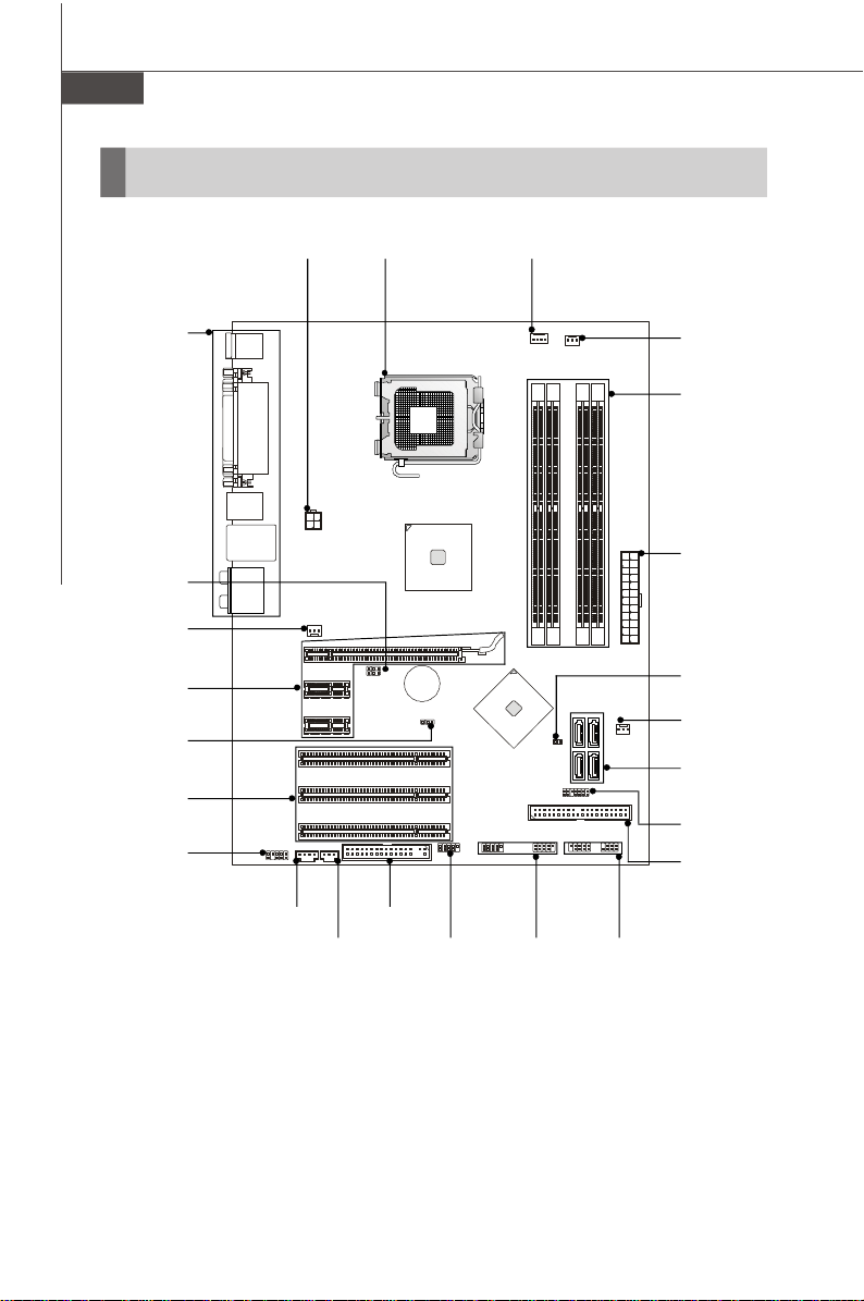
Quick Components Guide
Back Panel,
En-12
JFSB1~2,
En-21
SYSFAN2,
En-15
PCIE Slots,
En-22
JBAT1,
En-21
PCI Slots,
En-22
JAUD1,
En-18
JPW1,
En-11
JCD1,
En-16
JSP1,
En-19
CPU,
En-5
FDD1,
En-14
J1394_1,
En-19
(Optional)
CPUFAN1,
En-15
JUSB1~2,
En-20
SYSFAN3,
En-15
Memory,
En-9
ATX1,
En-11
JCI1,
En-16
SYSFAN1,
En-15
SATA1~4,
En-15
JTPM1,
En-16
IDE1,
En-14
JFP1~2,
En-17
En-4
Page 14
CPU (Central Processing Unit)
When you are installing the CPU, make sure to install the cooler to prevent
overheating. If you do not have the CPU cooler, consult your dealer before turning
on the computer.
For the latest information about CPU, please visit http://global.msi.com.tw/index.
php?func=cpuform
Important
Overheating
Overheating will seriously damage the CPU and system. Always make sure
the cooling fan can work properly to protect the CPU from overheating. Make
sure that you apply an even layer of thermal paste (or thermal tape) between
the CPU and the heatsink to enhance heat dissipation.
Replacing the CPU
While replacing the CPU, always turn off the ATX power supply or unplug the
power supply’s power cord from the grounded outlet first to ensure the safety
of CPU.
Overclocking
This mainboard is designed to support overclocking. However, please make
sure your components are able to tolerate such abnormal setting, while
doing overclocking. Any attempt to operate beyond product specifications is
not recommended. We do not guarantee the damages or risks caused
by inadequate operation or beyond product specifications.
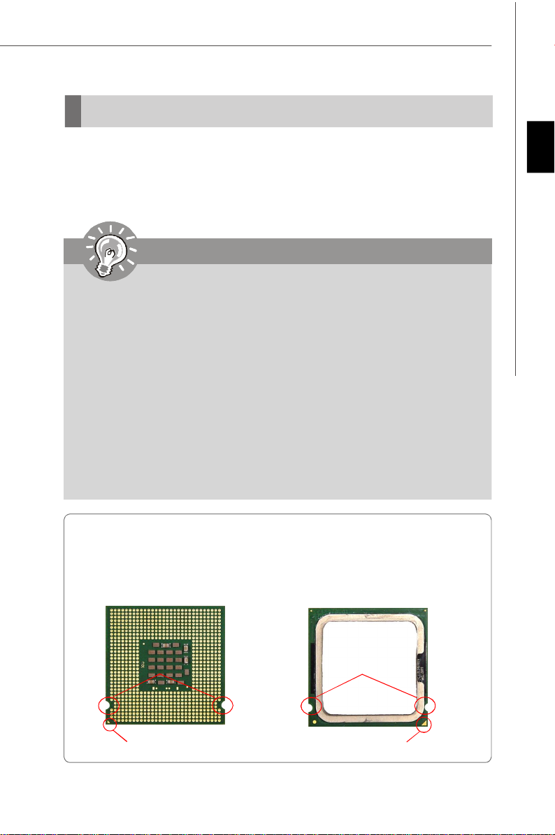
Introduction to LGA 775 CPU
The pin-pad side of LGA 775
CPU.
The surface of LGA 775 CPU.
Remember to apply some
thermal paste on it for better
heat dispersion.
English
Alignment Key Alignment Key
Yellow triangle is the Pin 1 indicator
Yellow triangle is the Pin 1 indicator
En-5
Page 15
MS-7392 Mainboard
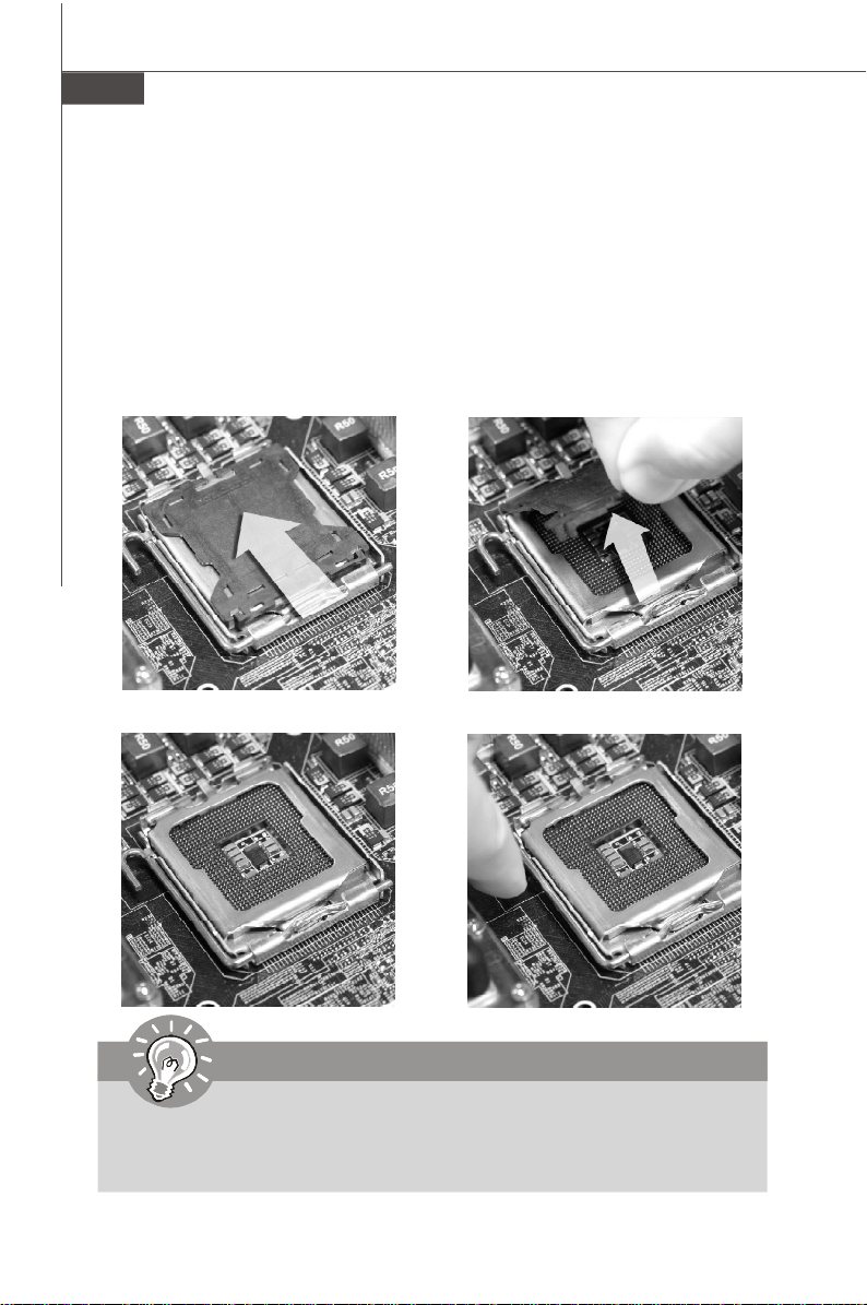
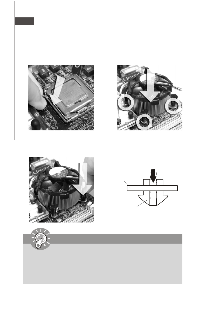
CPU & Cooler Installation
When you are installing the CPU, make sure the CPU has a cooler attached on
the top to prevent overheating. Meanwhile, do not forget to apply some thermal
paste on CPU before installing the heat sink/cooler fan for better heat dispersion.
Follow the steps below to install the CPU & cooler correctly. Wrong installation will
cause the damage of your CPU & mainboard.
1.The CPU socket has a plastic cap
on it to protect the contact from
damage. Before you install the CPU,
always cover it to protect the socket
pin.
2.Remove the cap from lever hinge
side (as the arrow shows).
3.The pins of socket reveal.
4.Open the load lever.
Important
1.Confirm if your CPU cooler is firmly installed before turning on your system.
2. Do not touch the CPU socket pins to avoid damaging.
3. The availability of the CPU land side cover depends on your CPU packing.
En-6
Page 16

5.Lift the load lever up and open the
load plate.
6.After confirming the CPU direction
for correct mating, put down the
CPU in the socket housing frame.
Be sure to grasp on the edge of
the CPU base. Note that the alignment keys are matched.
alignment
key
English
7.Visually inspect if the CPU is
seated well into the socket. If not,
take out the CPU with pure vertical
motion and reinstall.
8.Cover the load plate onto the
package.
En-7
Page 17

MS-7392 Mainboard
9.Press down the load lever lightly
onto the load plate, and then secure the lever with the hook under
retention tab.
11.Press the four hooks down to fasten
the cooler. Then rotate the locking
switch (refer to the correct direction
marked on it) to lock the hooks.
10. Align the holes on the mainboard
with the heatsink. Push down the
cooler until its four clips get
wedged into the holes of the
mainboard.
12.Turn over the mainboard to confirm that the clip-ends are correctly
inserted.
Mainboard
locking
switch
Hook
Important
1. Read the CPU status in BIOS (Chapter 3).
2. Whenever CPU is not installed, always protect your CPU socket pin with the
plastic cap covered (shown in Figure 1) to avoid damaging.
3. Mainboard photos shown in this section are for demonstration of the CPU/
cooler installation only. The appearance of your mainboard may vary depending on the model you purchase.
En-8
Page 18
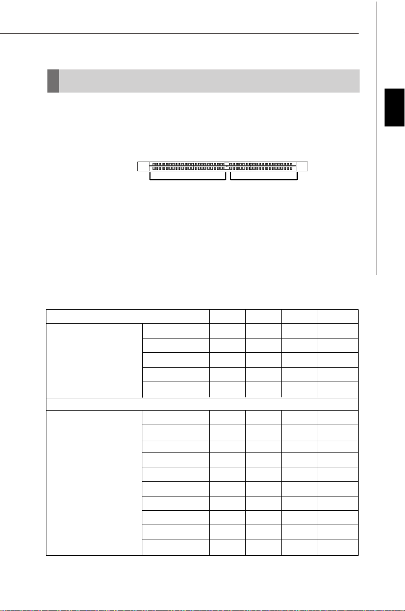
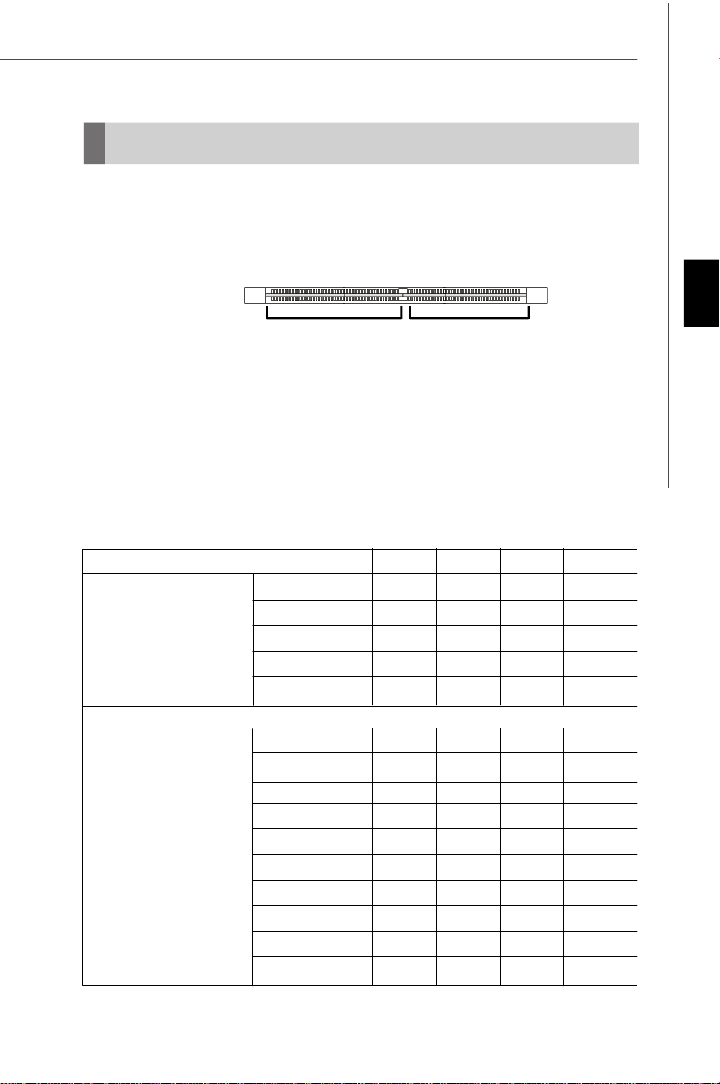
Memory
These DIMM slots are used for installing memory modules.
(For more information on compatible components, please visit http://global.msi.com.
tw/index.php?func=testreport)
DDR2
240-pin, 1.8V
Single-Channel: All DIMMs in GREEN
Dual-Channel: Channel A in GREEN; Channel B in ORANGE
64x2=128 pin 56x2=112 pin
Due to chipset limitations, to enable dual channel mode or single channel mode,
installing memory modules should refer to the following table.
Memory Installation Combination
(SS : single side, DS : double side, X : none installed memory)
DIMM1 DIMM2 DIMM3 DIMM4
Combination1 DS/SS X DS/SS X
Combination2 DS/SS X X DS/SS
Dual Channel Mode
Combination3 X DS/SS DS/SS X
Combination4 X DS/SS X DS/SS
Combination5 SS SS SS SS
English
Single Channel Mode
Combination1 DS/SS X X X
Combination2 X DS/SS X X
Combination3 X X DS/SS X
Combination4 X X X DS/SS
Combination5 SS SS X X
Combination6 X X SS SS
Combination7 SS SS DS/SS X
Combination8 SS SS X DS/SS
Combination9 DS/SS X SS SS
Combination10 X DS/SS SS SS
En-9
Page 19
MS-7392 Mainboard
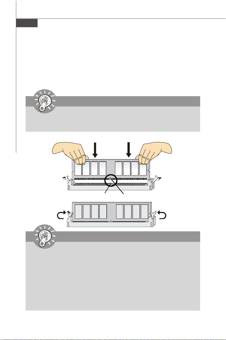
Installing Memory Modules
1. The memory module has only one notch on the center and will only fit in the right
orientation.
2. Insert the memory module vertically into the DIMM slot. Then push it in until the
golden finger on the memory module is deeply inserted in the DIMM slot. The plastic
clip at each side of the DIMM slot will automatically close when the memory module
is properly seated.
Important
You can barely see the golden finger if the memory module is properly inserted in the DIMM slot.
3. Manually check if the memory module has been locked in place by the DIMM slot
clips at the sides.
Volt
Notch
Important
- DDR2 memory modules are not interchangeable with DDR and the DDR2
standard is not backwards compatible. You should always install DDR2
memory modules in the DDR2 DIMM slots.
- In Dual-Channel mode, make sure that you install memory modules of the
same type and density in different channel DIMM slots.
- To enable successful system boot-up, always insert the memory modules
into the DIMM1 first.
- Due to the chipset resource deployment, the system density will only be
detected up to 3+GB (not full 4GB) when each DIMM is installed with a 1GB
memory module.
En-10
Page 20
Power Supply
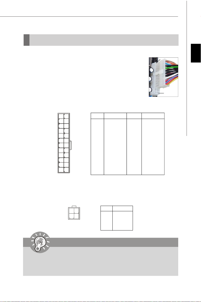
ATX 24-Pin Power Connector: ATX1
This connector allows you to connect an ATX 24-pin power supply.
To connect the ATX 24-pin power supply, make sure the plug of the
power supply is inserted in the proper orientation and the pins are
aligned. Then push down the power supply firmly into the connector.
You may use the 20-pin ATX power supply as you like. If you’d like
to use the 20-pin ATX power supply, please plug your power supply along with pin 1 & pin 13 (refer to the image at the right hand).
There is also a foolproof design on pin 11, 12, 23 & 24 to avoid
wrong installation.
Pin Definition
PIN SIGNAL
13 +3.3V
14 -12V
15 GND
16 PS-ON#
17 GND
18 GND
19 GND
20 Res
21 +5V
22 +5V
23 +5V
24 GND
ATX1
12
24
1
13
PIN SIGNAL
1 +3.3V
2 +3.3V
3 GND
4 +5V
5 GND
6 +5V
7 GND
8 PWR OK
9 5VSB
10 +12V
11 +12V
12 +3.3V
ATX 12V Power Connector: JPW1
This 12V power connector JPW1 is used to provide power to the CPU.
pin 13
pin 12
English
Pin Definition
3 4
1
JPW1
2
PIN SIGNAL
1 GND
2 GND
3 12V
4 12V
Important
1. Make sure that all the connectors are connected to proper ATX power
supplies to ensure stable operation of the mainboard.
2. Power supply of 350 watts (and above) is highly recommended for
system stability.
En-11
Page 21
MS-7392 Mainboard
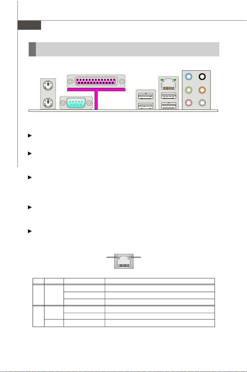
Back Panel
Mouse
Keyboard
Parallel Port
Serial Port USB Port
LAN Jack
Line-In
Line-Out
Mic
RS-Out
CS-Out
SS-Out
Mouse/Keyboard
The standard PS/2® mouse/keyboard DIN connector is for a PS/2® mouse/keyboard.
Parallel Port
A parallel port is a standard printer port that supports Enhanced Parallel Port (EPP)
and Extended Capabilities Parallel Port (ECP) mode.
Serial Port
The serial port is a 16550A high speed communications port that sends/ receives 16
bytes FIFOs. You can attach a serial mouse or other serial devices directly to the
connector.
USB Port
The USB (Universal Serial Bus) port is for attaching USB devices such as keyboard,
mouse, or other USB-compatible devices.
LAN Jack
The standard RJ-45 LAN jack is for connection to the Local Area Network (LAN). You
can connect a network cable to it.
Link IndicatorActivity Indicator
LED Color LED State condition
Off LAN link is not established.
Left Yellow On (steady state) LAN link is established.
On (brighter & pulsing)The computer is communicating with another computer on the LAN.
Green Off 10 Mbit/sec data rate is selected.
Right On 100 Mbit/sec data rate is selected.
Orange On 1000 Mbit/sec data rate is selected.
En-12
Page 22

Audio Ports
These audio connectors are used for audio devices. You can differentiate the color
of the audio jacks for different audio sound effects.
Line-In (Blue) - Line In, is used for external CD player, tapeplayer or other
audio devices.
Line-Out (Green) - Line Out, is a connector for speakers or headphones.
Mic (Pink) - Mic, is a connector for microphones.
RS-Out (Black) - Rear-Surround Out in 4/ 5.1/ 7.1 channel mode.
CS-Out (Orange) - Center/ Subwoofer Out in 5.1/ 7.1 channel mode.
SS-Out (Gray) - Side-Surround Out 7.1 channel mode.
English
En-13
Page 23
MS-7392 Mainboard
Connectors
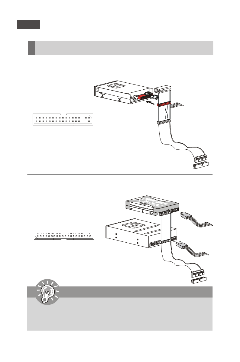
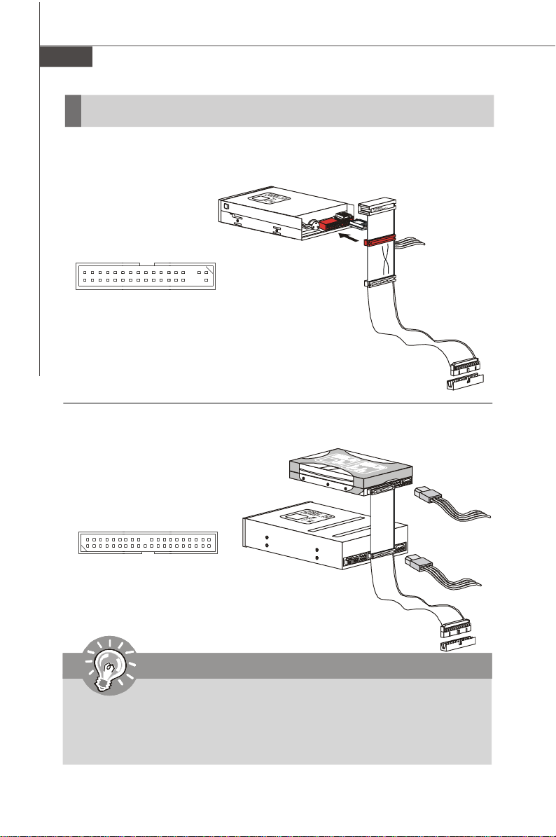
Floppy Disk Drive Connector: FDD1
This connector supports 360KB, 720KB, 1.2MB, 1.44MB or 2.88MB floppy disk drive.
FDD1
IDE Connector: IDE1
This connector supports IDE hard disk drives, optical disk drives and other IDE devices.
IDE1
Important
If you install two IDE devices on the same cable, you must configure the
drives separately to master / slave mode by setting jumpers. Refer to IDE
device’s documentation supplied by the vendors for jumper setting instructions.
En-14
Page 24
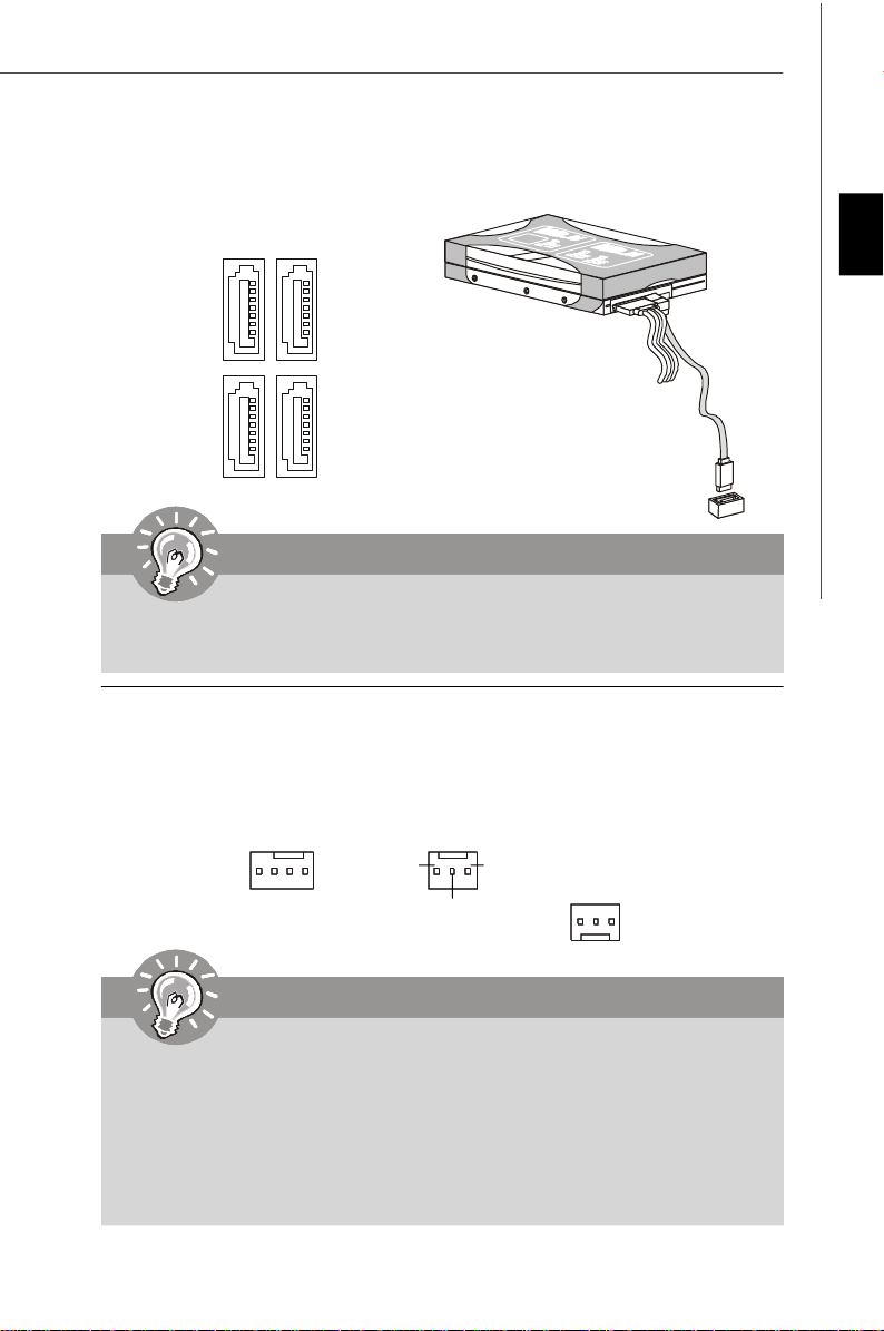
Serial ATA Connector: SATA1/ SATA2/ SATA3/ SATA4
This connector is a high-speed Serial ATA interface port. Each connector can
connect to one Serial ATA device.
SATA4SATA3
SATA2SATA1
Important
Please do not fold the Serial ATA cable into 90-degree angle. Otherwise, data
loss may occur during transmission.
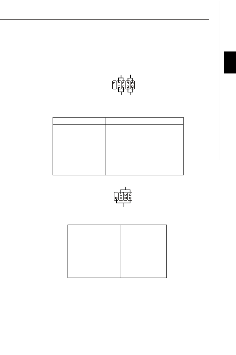
Fan Power Connectors: CPUFAN1/ SYSFAN1/ SYSFAN2 / SYSFAN3
The fan power connectors support system cooling fan with +12V. When connecting
the wire to the connectors, always note that the red wire is the positive and should
be connected to the +12V; the black wire is Ground and should be connected to GND.
If the mainboard has a System Hardware Monitor chipset on-board, you must use a
specially designed fan with speed sensor to take advantage of the CPU fan control.
English
+12V
GND
+12V
SENSOR
GND
SENSOR
SENSOR
+12V
GND
Control
SYSFAN1
CPUFAN1
SYSFAN3
SYSFAN2
Important
1. Please refer to the recommended CPU fans at processor’s official
website or consult the vendors for proper CPU cooling fan.
2. Fan cooler set with 3 or 4 pins power connector are both available for
CPUFAN1.
3. CPUFAN1 supports fan control. You can setup it in H/W Monitor of BIOS
Setup. You can install Dual Core Center utility that will automatically
control the CPU fan speed according to the actual CPU temperature.
En-15
Page 25

MS-7392 Mainboard
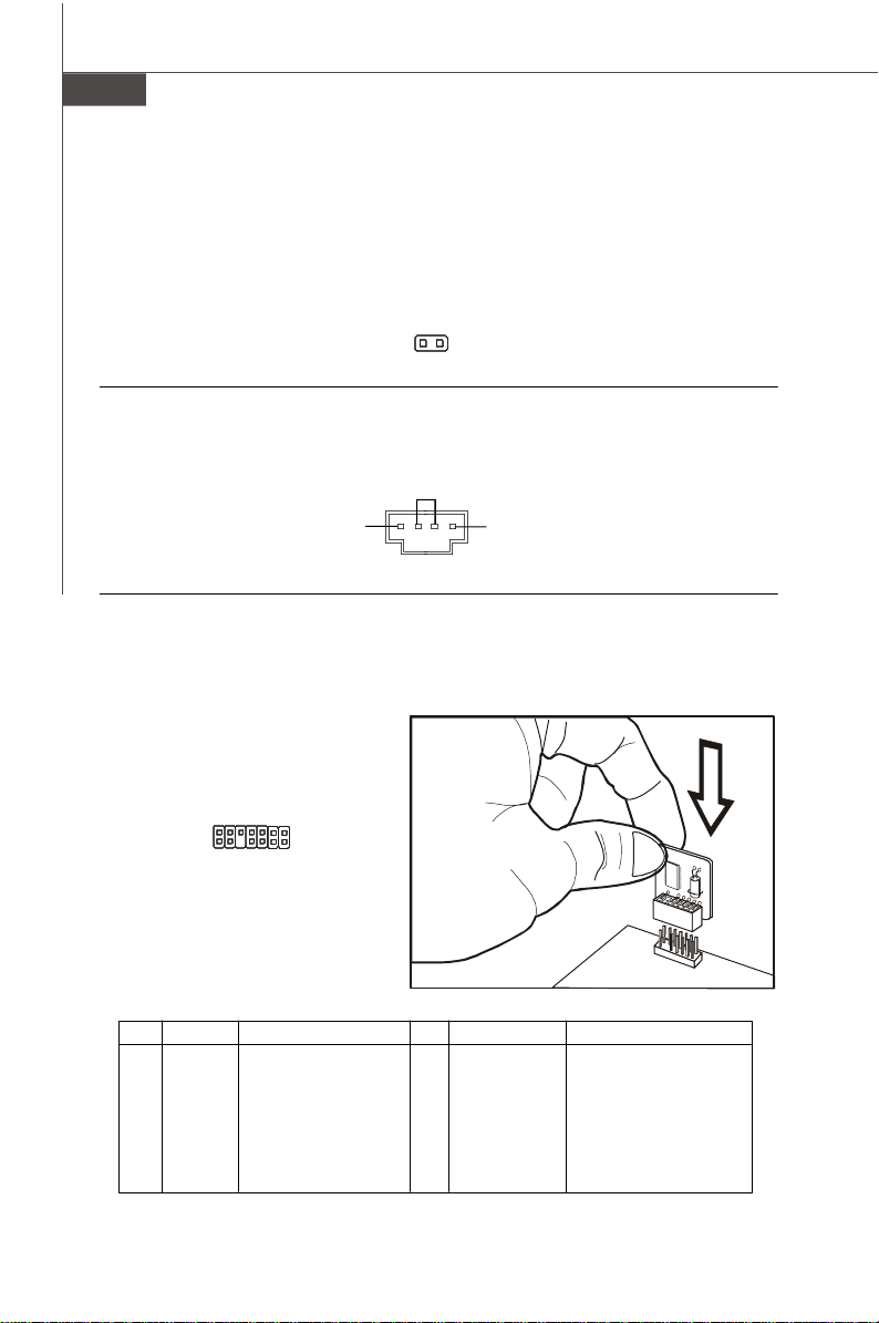
Chassis Intrusion Switch Connector: JCI1
This connector connects to a 2-pin chassis switch. If the chassis is opened, the
switch will be short. The system will record this status and show a warning message on the screen. To clear the warning, you must enter the BIOS utility and clear the
record.
C
I
N
G
T
N
R
D
U
2
1
JCI1
CD-In Connector: JCD1
This connector is provided for external audio input.
GND
L
R
JCD1
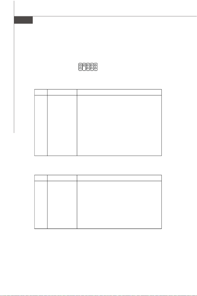
TPM Module connector: JTPM1
This connector connects to a TPM (Trusted Platform Module) module. Please refer to
the TPM security platform manual for more details and usages.
13
14
JTPM1
Pin Signal Description Pin Signal Description
1 LCLK LPC clock 2 3V dual/3V_STB 3V dual or 3V standby power
3 LRST# LPC reset 4 VCC3 3.3V power
5 LAD0 LPC address & data pin0 6 SIRQ Serial IRQ
7 LAD1 LPC address & data pin1 8 VCC5 5V power
9 LAD2 LPC address & data pin2 10 KEY No pin
11 LAD3 LPC address & data pin3 12 GND Ground
13 LFRAME# LPC Frame 14 GND Ground
1
2
En-16
Page 26
Front Panel Connectors: JFP1/ JFP2
These connectors are for electrical connection to the front panel switches and LEDs.
The JFP1 is compliant with Intel® Front Panel I/O Connectivity Design Guide.
HDD
Reset
LED
Switch
-
-
+
+
JFP1
9
10
Power
Switch
1
2
-
+
Power
LED
JFP1 Pin Definition
PIN SIGNAL DESCRIPTION
1 HD_LED + Hard disk LED pull-up
2 FP PWR/SLP MSG LED pull-up
3 HD_LED - Hard disk active LED
4 FP PWR/SLP MSG LED pull-up
5 RST_SW - Reset Switch low reference pull-down to GND
6 PWR_SW - Power Switch high reference pull-down to GND
7 RST_SW + Reset Switch high reference pull-up
8 PWR_SW + Power Switch low reference pull-up
9 RSVD_DNU Reserved. Do not use.
Power LED
JFP2
7
8
-
+
Speaker
1
2
+
-
JFP2 Pin Definition
PIN SIGNAL DESCRIPTION
1 GND Ground
2 SPK- Speaker3 SLED Suspend LED
4 BUZ+ Buzzer+
5 PLED Power LED
6 BUZ- Buzzer7 NC No connection
8 SPK+ Speaker+
English
En-17
Page 27
MS-7392 Mainboard
Front Panel Audio Connector: JAUD1
This connector allows you to connect the front panel audio and is compliant with
Intel® Front Panel I/O Connectivity Design Guide.
9
10
1
2
JAUD1
HD Audio Pin Definition
PIN SIGNAL DESCRIPTION
1 MIC_L Microphone - Left channel
2 GND Ground
3 MIC_R Microphone - Right channel
4 PRESENCE# Active low signal-signals BIOS that a High Definition Audio dongle
5 LINE out_R Analog Port - Right channel
6 MIC_JD Jack detection return from front panel microphone JACK1
7 Front_JD Jack detection sense line from the High Definition Audio CODEC
8 NC No control
9 LINE out_L Analog Port - Left channel
10 LINEout_JD Jack detection return from front panel JACK2
is connected to the analog header. PRESENCE# = 0 when a
High Definition Audio dongle is connected
jack detection resistor network
AC’97 Audio Pin Definition
PIN SIGNAL DESCRIPTION
1 MIC Microphone input signal
2 GND Ground
3 MIC_PWR Microphone power
4 NC No Control
5 LINE out_R Right channel audio signal to front panel
6 NC No Control
7 NC No Control
8 Key No pin
9 LINE out_L Left channel audio signal to front panel
10 NC No Control
En-18
Page 28
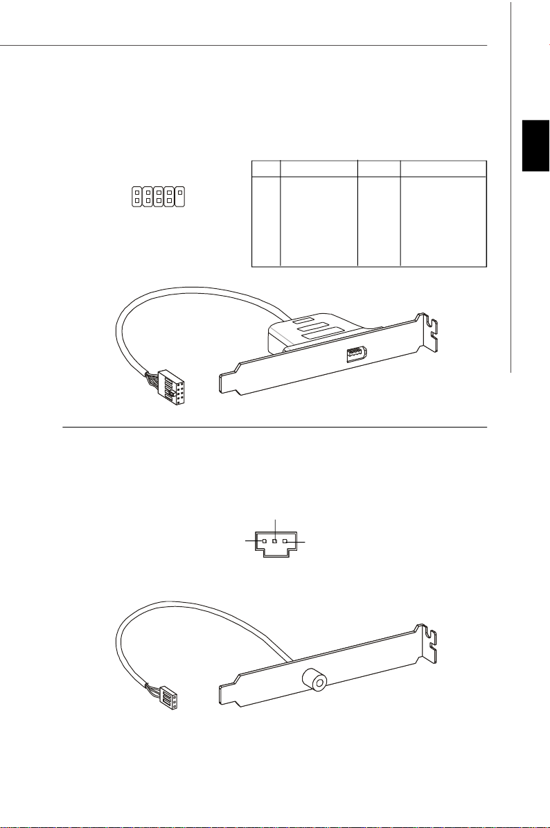
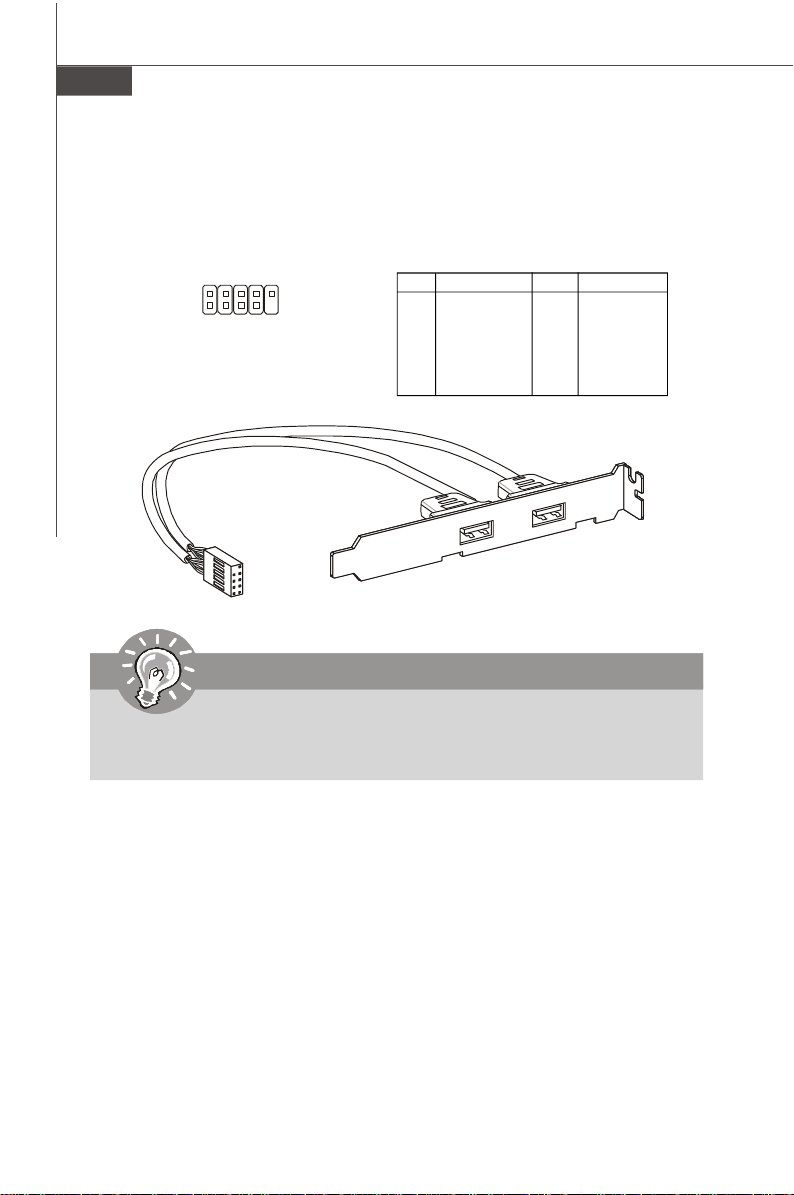
IEEE1394 Connector: J1394_1 (Optional)
This connector allows you to connect the IEEE1394 device via an optional IEEE1394
bracket.
Pin Definition
PIN SIGNAL PIN SIGNAL
2
1
J1394_1
9
10
1 TPA+ 2 TPA3 Ground 4 Ground
5 TPB+ 6 TPB7 Cable power 8 Cable power
9 Key (no pin) 10 Ground
IEEE1394 Bracket
(Optional)
S/PDIF-Out Connector: JSP1
This connector is used to connect S/PDIF (Sony & Philips Digital Interconnect Format)
interface for digital audio transmission.
English
GND
SPDIF-out
VCC
JSP1
S/PDIF Bracket
(Optional)
En-19
Page 29
MS-7392 Mainboard
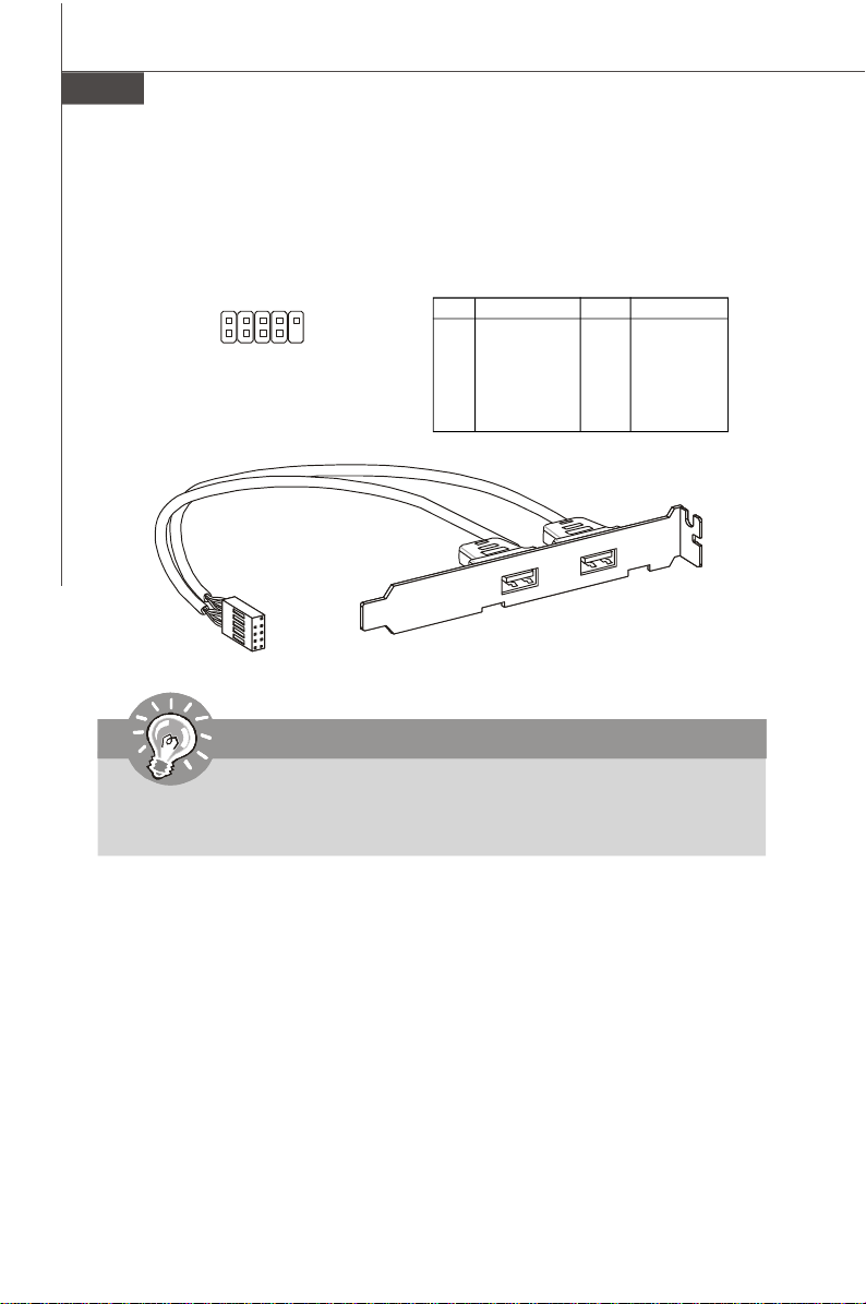
Front USB Connector: JUSB1/ JUSB2
This connector, compliant with Intel® I/O Connectivity Design Guide, is ideal for connecting high-speed USB interface peripherals such as USB HDD, digital cameras,
MP3 players, printers, modems and the like.
Pin Definition
2 10
1
JUSB1
JUSB2
9
PIN SIGNAL PIN SIGNAL
1 VCC 2 VCC
3 USB0- 4 USB15 USB0+ 6 USB1+
7 GND 8 GND
9 Key (no pin) 10 USBOC
USB 2.0 Bracket
(Optional)
Important
Note that the pins of VCC and GND must be connected correctly to avoid
possible damage.
En-20
Page 30
Jumpers
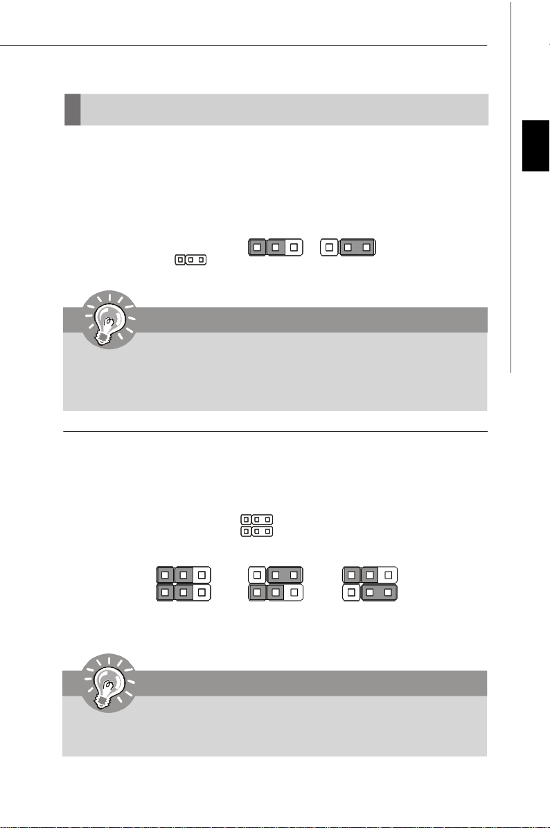
Clear CMOS Jumper: JBAT1
There is a CMOS RAM onboard that has a power supply from an external battery to
keep the data of system configuration. With the CMOS RAM, the system can automatically boot OS every time it is turned on. If you want to clear the system configuration,
set the jumper to clear data.
1 3
1 3
JBAT1
1
Keep Data
Clear Data
Important
You can clear CMOS by shorting 2-3 pin while the system is off. Then return
to 1-2 pin position. Avoid clearing the CMOS while the system is on; it will
damage the mainboard.
Hardware Overclock FSB Jumpers: JFSB1/ JFSB2
You can overclock the FSB to increase the processor frequency by changing the
jumpers JFSB1 and JFSB2. Follow the instructions below to set the FSB.
JFSB1
JFSB2
1 3
English
1 3
200 MHz
(Default)
1 3
266 MHz
1 3
333 MHz
Important
1. Make sure that you power off the system before changing the jumpers.
2. Please default OC jumper if you need to support FSB400 CPU.
En-21
Page 31

MS-7392 Mainboard
Slots
PCI (Peripheral Component Interconnect) Express Slot
The PCI Express slot supports the PCI Express interface expansion card.
The PCI Express x 16 supports up to 4.0 GB/s transfer rate.
The PCI Express x 1 supports up to 250 MB/s transfer rate.
PCI Express x16 Slot
PCI Express x1 Slot
PCI (Peripheral Component Interconnect) Slot
The PCI slot supports LAN card, SCSI card, USB card, and other add-on cards that
comply with PCI specifications.
32-bit PCI Slot
Important
When adding or removing expansion cards, make sure that you unplug the
power supply first. Meanwhile, read the documentation for the expansion
card to configure any necessary hardware or software settings for the expansion card, such as jumpers, switches or BIOS configuration.
PCI Interrupt Request Routing
The IRQ, acronym of interrupt request line and pronounced I-R-Q, are hardware lines
over which devices can send interrupt signals to the microprocessor. The PCI IRQ
pins are typically connected to the PCI bus pins as follows:
Order 1 Order 2 Order 3 Order 4
PCI Slot 1 INT A# INT B# INT C# INT D#
PCI Slot 2 INT B# INT C# INT D# INT A#
PCI Slot 3 INT C# INT D# INT A# INT B#
En-22
Page 32

BIOS Setup
This chapter provides basic information on the BIOS Setup program and allows you
to configure the system for optimum use. You may need to run the Setup program
when:
* An error message appears on the screen during the system booting up, and requests
you to run BIOS SETUP.
* You want to change the default settings for customized features.
Important
1.The items under each BIOS category described in this chapter are under
continuous update for better system performance. Therefore, the description may be slightly different from the latest BIOS and should be held for
reference only.
2.Upon boot-up, the 1st line appearing after the memory count is the BIOS
version. It is usually in the format:
A7392IMS V2.0 071307 where:
1st digit refers to BIOS maker as A = AMI, W = AWARD, and P =
PHOENIX.
2nd - 5th digit refers to the model number.
6th digit refers to the chipset as I = Intel, N = nVidia, and V = VIA.
7th - 8th digit refers to the customer as MS = all standard customers.
V2.0 refers to the BIOS version.
071307 refers to the date this BIOS was released.
English
En-23
Page 33

MS-7392 Mainboard
Entering Setup
Power on the computer and the system will start POST (Power On Self Test) process.
When the message below appears on the screen, press <DEL> key to enter Setup.
Press DEL to enter SETUP
If the message disappears before you respond and you still wish to enter Setup,
restart the system by turning it OFF and On or pressing the RESET button. You may
also restart the system by simultaneously pressing <Ctrl>, <Alt>, and <Delete> keys.
Getting Help
After entering the Setup menu, the first menu you will see is the Main Menu.
Main Menu
The main menu lists the setup functions you can make changes to. You can use the
arrow keys (↑↓ ) to select the item. The on-line description of the highlighted setup
function is displayed at the bottom of the screen.
Sub-Menu
If you find a right pointer symbol (as shown in the right view)
appears to the left of certain fields that means a sub-menu
containing additional options can be launched from this field.
You can use control keys (↑↓ ) to highlight the field and
press <Enter> to call up the sub-menu. Then you can use the
control keys to enter values and move from field to field within a sub-menu. If you
want to return to the main menu, just press <Esc >.
General Help <F1>
The BIOS setup program provides a General Help screen. You can call up this screen
from any menu by simply pressing <F1>. The Help screen lists the appropriate keys
to use and the possible selections for the highlighted item. Press <Esc> to exit the
Help screen.
En-24
Page 34

The Main Menu
Once you enter AMI® or AWARD® BIOS CMOS Setup Utility, the Main Menu will appear
on the screen. The Main Menu allows you to select from ten setup functions and two
exit choices. Use arrow keys to select among the items and press <Enter> to accept
or enter the sub-menu.
Standard CMOS Features
Use this menu for basic system configurations, such as time, date etc.
Advanced BIOS Features
Use this menu to setup the items of AMI® special enhanced features.
Integrated Peripherals
Use this menu to specify your settings for integrated peripherals.
Power Management Setup
Use this menu to specify your settings for power management.
PnP/PCI Configurations
This entry appears if your system supports PnP/PCI.
H/W Monitor
This entry shows your PC health status.
Frequency/Voltage Control
Use this menu to specify your settings for frequency/voltage control and overclocking.
Load Fail-Safe Defaults
Use this menu to load the default values set by the BIOS vendor for stable system
performance.
Load Optimized Defaults
Use this menu to load the default values set by the mainboard manufacturer specifically for optimal performance of the mainboard.
BIOS Setting Password
Use this menu to set the password for BIOS.
Save & Exit Setup
Save changes to CMOS and exit setup.
Exit Without Saving
Abandon all changes and exit setup.
En-25
English
Page 35

MS-7392 Mainboard
When enter the BIOS Setup utility, follow the processes below for general use.
1. Load Optimized Defaults : Use control keys (↑↓) to highlight the Load
Optimized Defaults field and press <Enter> , a message as below appears:
Select [Ok] and press Enter to load the default settings for optimal system
performance.
2. Setup Date/ Time : Select the Standard CMOS Features and press <Enter> to
enter the Standard CMOS Features-menu. Adjust the Date, Time fields.
3. Save & Exit Setup : Use control keys (↑↓) to highlight the Save & Exit Setup
field and press <Enter> , a message as below appears:
Select [Ok] and press Enter to save the configurations and exit BIOS Setup utility.
Important
The configuration above are for general use only. If you need the detailed
settings of BIOS, please see the manual in English version on MSI website.
En-26
Page 36

4. H/W Monitor Introduction
Chassis Intrusion
The field enables or disables the feature of recording the chassis intrusion status
and issuing a warning message if the chassis is once opened. To clear the warning
message, set the field to [Reset]. The setting of the field will automatically return to
[Enabled] later.
CPU Smart FAN Target
The mainboard provides the Smart Fan function which can control the CPU fan speed
automatically depending on the current temperature to keep it with in a specific range.
You can select a fan target value here. If the current CPU fan temperature reaches to
the target value, the smart fan function will be activated. It provides several sections
to speed up for cooling down automaticlly.
CPU Min.FAN Speed (%)
This field is used to set the minimum CPU fan speed.
SYS FAN1 Control
The field allows you to determine whether the system fan connected to SYSFAN1
will work or not when the system is turned on.
English
PC Health Status
CPU/ System Temperature, CPU FAN/ SYS FAN1/ 2 Speed, CPU Vcore, 3.3V,,
5V, 12V
These items display the current status of all of the monitored hardware devices/
components such as CPU voltage, temperatures and all fans’ speeds.
En-27
Page 37

MS-7392 Mainboard
Software Information
Take out the Driver/Utility CD that is included in the mainboard package, and place it
into the CD-ROM drive. The installation will auto-run, simply click the driver or utility
and follow the pop-up screen to complete the installation. The Driver/Utility CD contains the:
Driver menu - The Driver menu shows the available drivers. Install the driver by your
desire and to activate the device.
Utility menu - The Utility menu shows the software applications that the mainboard
supports.
WebSite menu- The WebSite menu shows the necessary websites.
Important
Please visit the MSI website to get the latest drivers and BIOS for better
system performance.
En-28
Page 38

G31P Neo2 Serie
Benutzerhandbuch
Deutsch
Deutsch
De-1
Page 39

MS-7392 Mainboard
Spezifikationen
Prozessoren
- Intel® CoreTM2 Quad, CoreTM2 Duo, Pentium® E2XXX und Celeron
4XX Prozessoren für Sockel LGA775
(Weitere CPU Informationen finden Sie unter http://global.msi.com.
tw/index.php?func=cpuform)
FSB (Front-Side-Bus)
- 1333/ 1066/ 800 MHz
Chipsatz
- North-Bridge: Intel® P31/ G31 Chipsatz
- South-Bridge: Intel® ICH7R/ ICH7 Chipsatz
Speicher
- DDR2 800/ 667 SDRAM (max. 4GB)
- 4 DDR2 DIMMs (240Pin/ 1.8V)
(Weitere Informationen zu kompatiblen Speichermodulen finden Sie
unter http://global.msi.com.tw/index.php?func=testreport)
LAN
- Unterstützt die PCI Express LAN 10/ 100/ 1000 Fast Ethernet über
Realtek® RTL8111C/ RTL8111B (Optional)
IEEE 1394 (Optional)
- Onboard Chip über VIA® VT6308P
- Übertragungsgeschwindigkeit von bis zu 400 Mbps
Audio
- Onboard Soundchip Realtek® ALC888
- 8-Kanal Audio-Ausgang mit “Jack Sensing” Funktion
- Erfüllt die Azalia Spezifikation
- Zertifiziert für das Microsoft® Windows® VistaTM Premium
Betriebssystem
®
De-2
IDE
- 1 IDE Port über Intel® ICH7R/ ICH7
- Unterstützt die Betriebmodi mit Ultra DMA 66/ 100
- Unterstützt die Betriebmodi mit PIO, Bus Masterimg
SATA
- 4 SATA II Ports über Intel® ICH7R/ ICH7
- Unterstützt vier SATA Geräte
- Unterstützt Datenübertragungsraten von bis zu 3Gb/s
RAID
- Unterstützt die Modi RAID 0/ 1/ 0+1/ 5 über Intel® ICH7R
Page 40

Diskette
- 1 Disketten Anschluss
- Unterstützt 1 FDD mit 360KB, 720KB, 1.2MB, 1.44MB und 2.88MB
Anschlüsse
Hintere Ein-/ und Ausgänge
- 1 PS/2 Mausanschluss
- 1 PS/2 Tastaturanschluss
- 1 Parallele Schnittstelle
- 1 Serielle Anschluss
- 1 LAN Anschluss
- 4 USB Anschlüsse
- 6 Audiobuchsen
On-Board Stiftleiste/ Anschlüsse
- 2 USB Stiftleisten
- 1 CD-Stiftleiste für Audio Eingang
- 1 S/PDIF-Ausgang Stiftleiste
- 1 Audio Stiftleiste für Gehäuse Audio Ein-/ Ausgänge
- 1 Gehäusekontaktschalter
- 1 1394 Stiftleiste (Optional)
- 1 JTPM Schnittstelle
Schnittstellen
- 1 PCI Express x16 Schnittstelle
- 2 PCI Express x1 Schnittstellen
- 3 PCI Schnittstellen (unterstützt 3.3V/ 5V PCI Bus Interface)
Form Faktor
- ATX (30.5cm X 23.6cm)
Deutsch
Montage
- 6 Montagebohrungen
De-3
Page 41

MS-7392 Mainboard
Komponenten-Übersicht
Back Panel,
De-12
JFSB1~2,
De-21
SYSFAN2,
De-15
PCIE Slots,
De-22
JBAT1,
De-21
PCI Slots,
De-22
JAUD1,
De-18
JPW1,
De-11
JCD1,
De-16
JSP1,
De-19
CPU,
De-5
FDD1,
De-14
J1394_1,
De-19
(Optional)
CPUFAN1,
De-15
JUSB1~2,
De-20
SYSFAN3,
De-15
Memory,
De-9
ATX1,
De-11
JCI1,
De-16
SYSFAN1,
De-15
SATA1~4,
De-15
JTPM1,
De-16
IDE1,
De-14
JFP1~2,
De-17
De-4
Page 42

CPU (Central Processing Unit)
Wenn Sie die CPU einbauen, stellen Sie bitte sicher, dass Sie auf der CPU
einen Kühler anbringen, um Überhitzung zu vermeiden. Verfügen Sie über
keinen Kühler, setzen Sie sich bitte mit Ihrem Händler in Verbindung, um einen
solchen zu erwerben und zu installieren.
Um die neuesten Informationen zu unterstützten Prozessoren zu erhalten,
besuchen Sie bitte http://global.msi.com.tw/index.php?func=cpuform
Wichtig
Überhitzung
Überhitzung beschädigt die CPU und das System nachhaltig, stellen Sie
stets eine korrekte Funktionsweise des CPU Kühlers sicher, um die CPU vor
Überhitzung zu schützen. Überprüfen Sie eine gleichmäßige Schicht der
thermischen Paste (oder thermischen Klebeandes) zwischen der CPU und
dem Kühlblech anwenden, um Wärmeableitung zu erhöhen.
CPU Wechsel
Stellen Sie vor einem Wechsel des Prozessors stets sicher, dass das ATX
Netzteil ausgeschaltet und der Netzstecker gezogen ist, um die Unversehrtheit
der CPU zu gewährleisten.
Übertakten
Dieses Motherboard wurde so entworfen, dass es Übertakten unterstützt.
Stellen Sie jedoch bitte sicher, dass die betroffenen Komponenten mit den
abweichenden Einstellungen während des Übertaktens zurecht kommen.
Von jedem Versuch des Betriebes außerhalb der Produktspezifikationen
kann nur abgeraten werden. Wir übernehmen keinerlei Garantie für die
Schäden und Risiken, die aus unzulässigem oder Betrieb jenseits der
Produktspezifikationen resultieren.
Erklärung zur LGA 775 CPU
Die Pin-Seite der LGA 775 CPU.
Die Obserseite der LGA 775
CPU.
Vergessen Sie nicht, etwas
Siliziumwärmeleitpaste auf die
CPU aufzutragen,um eine
Ableitung der Hitze zu erzielen.
Deutsch
Alignment Key Alignment Key
Gelbes Dreieck ist der Anzeiger Pin 1
Gelbes Dreieck ist der Anzeiger Pin 1
De-5
Page 43

MS-7392 Mainboard
CPU & Kühler Einbau
Wenn Sie die CPU einbauen, stellen Sie bitte sicher, dass Sie auf der CPU einen
Kühler anbringen, um Überhitzung zu vermeiden. Vergessen Sie nicht, etwas
Siliziumwärmeleitpaste auf die CPU aufzutragen, bevor Sie den Prozessorkühler
installieren, um eine Ableitung der Hitze zu erzielen.
Folgen Sie den Schritten unten, um die CPU und den Kühler ordnungsgemäß zu
installieren. Ein fehlerhafter Einbau führt zu Schäden an der CPU und dem
Mainboard.
1.Der CPU-Sockel besitzt zum Schutz
eine Plastikabdeckung. Lassen Sie
vor der Installtion diese
Schutzkappe auf dem Sockel um
Schäden zu vermeiden.
3.Sie sehen jetzt die Pins des Sockels.
2.Entfernen Sie zuerst die
Schutzkappe wie abgebildet in
Pfeilrichtung.
4. Öffnen Sie den
Sockelverschlusshebel.
De-6
Page 44

Wichtig
1.Stellen Sie sicher, dass Ihr CPU Küler fest eingebaut ist, bevor Sie Ihr
System anschalten.
2.Berühren Sie die Pins des CPU Sockels nicht, um Schaden zu vermeden.
3. Sie Verfügbarkeit der Abdeckung der Abschlussfläche hängt von der
Verpackung Ihrer CPU ab.
5.Klappen Sie den Hebel ganz auf
und öffnen Sie die
Metallverschlussklappe.
6.Vergewissem Sie sich anhand der
Justiermarkierungen und dem
gelben Dreieck, daß die CPU in der
korrekten Position ist. Setzen Sie
anschließend die CPU in den
Sockel.
alignment
key
Deutsch
7.Begutachten Sie, ob die CPU richtig
im Sockel sitzt. Falls nicht, zeihen
Sie die CPU durch eine rein vertikale
Bewegung wieder heraus.
Versuchen Sie es erneut..
8.Schließen Sie die Abdeckung des
Sockels.
De-7
Page 45
MS-7392 Mainboard
9.Drücken Sie den Verschlusshebel
mit leichtem Druck nach unten und
arretieren Sie den Hebel unter dem
Rückhaltenhaken des CPU-Sockels.
11.Drücken Sie die vier Stifte nach unten
um den Kühler zu arretieren. Drehen
Sie dann jeweils den Verschluss der
Stifte (Richtung ist auf dem Kühler
markiert).
10. Frühren Sie den CPU-Kühler über
den CPU-Sockel und positionieren
Sie die Arretierungsstifte des
Kühlers über die dafür
vorgesehenen Löcher des
Mainboards. Drücken Sie den
Kühler nach unten bis die Stifte in
den Löchern eingerastet.
12.Drehen Sie das Mainboard um und
vergewissern Sie sich, dass das
der Kühler korrekt installiert ist.
Mainboard
locking
switch
Hook
Wichtig
1. Prüfen Sie die Status der CPU im BIOS (Kapitel 3).
2. Wenn keine CPU installiert ist, schützen Sie immer den CPU-Sockel
durch die Plastikabdeckung (Figur 1).
3. Die Mainboard Fotos, die in diesem Abschnitt gezeigt werden, sind für
Demonstration der CPU/ Kühler Installation. Das Aussehen Ihres
mainboard kann abhangig von dem Modell schwanken, das Sie kaufen.
De-8
Page 46
Speicher
Diese DIMM-Steckplätze nehmen Arbeitsspeichermodule auf.
(Die neusten Informationen über kompatible Bauteile finden Sie unter http://global.
msi.com.tw/index.php?func=testreport)
DDR2
240-polig, 1.8V
Single-Channel: Alle DIMMs sind GRÜN Farbe
Dual-Channel: Channel A sind GRÜN Farbe; Channel B sind
ORANGE Farbe.
64x2=128 Pole 56x2=112 Pole
Wegen der Chipsatzbeschränkungen, beachten Sie folgende Tabelle für den Einsatz
des Dual Channel und Single Channel Modus.
Speicherkombination
(SS : einseitige Speicherbestückung, DS : zweiseitige Speicheranordnung,
X : freie Speicherslots)
DIMM1 DIMM2 DIMM3 DIMM4
Kombination1 DS/SS X DS/SS X
Kombination2 DS/SS X X DS/SS
Dual Channel Mode
Kombination3 X DS/SS DS/SS X
Kombination4 X DS/SS X DS/SS
Kombination5 SS SS SS SS
Kombination1 DS/SS X X X
Kombination2 X DS/SS X X
Kombination3 X X DS/SS X
Kombination4 X X X DS/SS
Single Channel Mode
Kombination5 SS SS X X
Kombination6 X X SS SS
Kombination7 SS SS DS/SS X
Kombination8 SS SS X DS/SS
Kombination9 DS/SS X SS SS
Kombination10 X DS/SS SS SS
Deutsch
De-9
Page 47

MS-7392 Mainboard
Installieren der Arbeitsspeichermodule
1. Das Arbeitsspeichermodul hat nur eine Kerbe in der Mitte und passt nur in eine
Richtung in den Steckplatz.
2. Stecken Sie das Arbeitsspeichermodul senkrecht in den DIMM-Steckplatz ein.
Drücken Sie anschließend das Arbeitsspeichermodul nach unten, bis die
Kontaktseite richtig tief in dem DIMM-Steckplatz sitzt. Der Kunststoffbügel an jedem
Ende des DIMM-Steckplatzes schnappt automatisch ein, wenn das
Arbeitsspeichermodul richtig eingesetzt ist.
Wichtig
Die goldenen Kontakte sind kaum zu sehen, wenn das Arbeitsspeichermodul
richtig im DIMM-Steckplatz sitzt.
3. Prüfen Sie von Hand, ob das Arbeitsspeichermodul von den seitlichen Bügeln am
DIMM-Steckplatz richtig gehalten wird.
Volt
Notch
Wichtig
- DDR2 und DDR können nicht untereinander getauscht werden und der
Standard DDR2 ist nicht rückwärtskompatibel, installieren Sie DDR2
Speichermodule stets in DDR2 DIMM Slots
- Stellen Sie im Zweikanalbetrieb bitte sicher, dass Sie Module des gleichen
Typs und identischer Speicherdichte in den DDR2 DIMM Slots
unterschiedlicher Kanäle verwenden.
- Um einen sicheren Systemstart zu gewährleisten, bestücken Sie immer
DIMM 1 zuerst.
- Aufgrund der Chipsatzressourcennutzung wird nur eine Systemdichte
bis 3+GB (nicht volle 4GB) erkannt, wenn jeder DIMM mit einem 1GB
Arbeitsspeichermodul besetzt wird.
De-10
Page 48

Stromversorgung
ATX 24-poliger Stromanschluss: ATX1
Mit diesem Anschluss verbinden Sie den ATX 24-poligen Anschluss
des Netzteils. Achten Sie bei dem Verbinden des ATX 24-poligen
Stromanschlusses darauf, dass der Anschluss des Netzteils richtig
auf den Anschluss an der Hauptplatine ausgerichtet ist. Drücken
Sie dann den Anschluss des Netzteils fest nach unten, um eine
richtige Verbindung zu gewährleisten.Sie können auch den 20poligen ATX-Stromanschluss des Netzteils verwenden. In diesem
Fall muss eine Ecke des 20-poligen ATX-Stromanschlusses des
Netzteils auf den Pol 1 bzw. Pol 13 des Anschlusses an der
Hauptplatine ausgerichtet werden (siehe Abbildung rechts). Pol 11, 12, 23 und 24
sind verpolungssicher ausgeführt, um eine falsche Installation zu vermeiden.
Polzuweisung
PIN SIGNAL
13 +3.3V
14 -12V
15 GND
16 PS-ON#
17 GND
18 GND
19 GND
20 Res
21 +5V
22 +5V
23 +5V
24 GND
ATX1
12
24
1
13
PIN SIGNAL
1 +3.3V
2 +3.3V
3 GND
4 +5V
5 GND
6 +5V
7 GND
8 PWR OK
9 5VSB
10 +12V
11 +12V
12 +3.3V
ATX 12V Stromanschluss: JPW1
Dieser 12V Stromanschluss wird verwendet, um die CPU mit Strom zu versorgen.
pin 13
pin 12
Deutsch
Polzuweisung
3 4
1
JPW1
2
PIN SIGNAL
1 GND
2 GND
3 12V
4 12V
Wichtig
1. Stellen Sie sicher, dass diese Anschlüsse mit den richtigen Anschlüssen
des Netzteils verbunden werden, um einen stabilen Betrieb der
Hauptplatine sicherzustellen.
2. Für die Systemstabilität ist ein Netzteil mit 350 Watt (oder noch mehr)
empfehlenswert.
De-11
Page 49

MS-7392 Mainboard
Rücktafel
Maus
Tastatur
Parallele Port
Serielle Port
LAN Jack
USB Port
Line-In
Line-Out
Mic
RS-Out
CS-Out
SS-Out
Maus/Tastatur
Die Standard PS/2® Maus/Tastatur Stecker Mini DIN ist für eine PS/2® Maus/Tastatur.
Parallele Schnittstelle
Die Parallele Schnittstelle ist eine Standard Druckerschnittstelle, die ebenso als Enhanced Parallel Port (EPP) und als Extended Capabilities Parallel Port (ECP) betrieben
werden kann.
Serielle Schnittstelle
Bei der Seriellen Schnittstelle handelt es sich um eine 16550A Hochgeschwindigkeitskommunikationsschnittstelle, die 16 Bytes FIFOs sendet/empfängt. An den Stecker
können Sie direkt eine Serielle Maus oder ein anderes Serielles Gerät anschließen.
USB Port
Dieser USB (Universal Serial Bus) Anschluss zum direkten Anschluss von USBGeräten, wie etwa Tastatur, Maus oder weiterer USB-kompatibler Geräte.
LAN Anschluss
Die Standard RJ-45 Buchse ist für Anschlus zum an ein Lokales Netzwerk (Local
Area Network - LAN). Hier kann ein Netzwerkkabel angeschlossen werden.
Link IndicatorActivity Indicator
LED Farbe LED Status Zustand
Aus Keine Verbindung mit dem LAN.
Links Yellow An (Dauerleuchten) Verbindung mit dem LAN.
An (heller & pulsierend) Der Computer kommuniziert mit einem anderen Rechner im LAN.
Grün Aus Gewählte Datenrate 10 MBit/s.
Rechts An Gewählte Datenrate 100 MBit/s.
Orange An Gewählte Datenrate 1000 MBit/s.
De-12
Page 50

Audio Ports
These audio connectors are used for audio devices. You can differentiate the color
of the audio jacks for different audio sound effects.
Line-In (Blue) - Line In, is used for external CD player, tapeplayer or other
audio devices.
Line-Out (Green) - Line Out, is a connector for speakers or headphones.
Mic (Pink) - Mic, is a connector for microphones.
RS-Out (Black) - Rear-Surround Out in 4/ 5.1/ 7.1 channel mode.
CS-Out (Orange) - Center/ Subwoofer Out in 5.1/ 7.1 channel mode.
SS-Out (Gray) - Side-Surround Out 7.1 channel mode.
Deutsch
De-13
Page 51
MS-7392 Mainboard
Anschlüsse
Anschluss des Diskettenlaufwerks: FDD1
Diese Anschluss unterstützt ein Diskettenlaufwerke mit 360KB, 720KB, 1.2MB, 1.
44MB oder 2.88MB Kapazität.
FDD1
IDE Anschluss: IDE1
An diesen Anschluss können IDE Festplatten, optische Laufwerke und andere Geräte
betrieben werden.
IDE1
Wichtig
Verbinden Sie zwei Laufwerke über ein Kabel, müssen Sie das zweite
Laufwerk im Slave-Modus konfigurieren, indem Sie entsprechend den Jumper
setzen. Entnehmen Sie bitte die Anweisungen zum Setzen des Jumpers der
Dokumentation der IDE Geräte, die der Festplattenhersteller zur Verfügung
stellt.
De-14
Page 52

Serial ATA Anschluss: SATA1/ SATA2/ SATA3/ SATA4
Der Anschluss ist eine Hochgeschwindigkeits Schnittstelle der Serial ATA. Pro
Anschluss kann ein S-ATA Gerät angeschlossen werden.
SATA4SATA3
SATA2SATA1
Wichtig
Bitte falten Sie das Serial ATA Kabel nicht in einem Winkel von 90 Grad, da
dies zu Datenverlusten während der Datenübertragung führt.
Stromanschlüsse für Lüfter: CPUFAN1/ SYSFAN1/ SYSFAN2 /
SYSFAN3
Die Anschlüsseunterstützen aktive Systemlüfter mit + 12V. CPU FAN kann Smart
FAN Funktion unterstützen. Wenn Sie den Anschluss herstellen, sollten Sie immer
darauf achten, dass der rote Draht der positive Pol ist, und mit +12V verbunden
werden sollte, der schwarze Draht ist der Erdkontakt und sollte mit GND verbunden
werden. Ist Ihr Mainboard mit einem Chipsatz zur Überwachung der Systemhardware
versehen, dann brauchen Sie einen speziellen Lüfter mit Tacho, um die Vorteile der
Steuerung des CPU Lüfters zu nutzen.
Deutsch
S
+
G
C
E
1
o
N
N
2
n
D
V
S
t
r
O
o
l
R
CPUFAN1
SENSOR
SYSFAN1
SYSFAN3
+12V
GND
+12V
SEN-
GND
SYSFAN2
SOR
Wichtig
1. Bitte informieren Sie sich auf der offiziellen Website vom Prozessor
über empfohlene CPU Kühler oder fragen Sie Ihren Händler nach einem
geeigneten Lüfter.
2. CPUFAN1 kann die Lüfter mit drei- und vierpolige Stecker unterstützen..
3. CPUFAN1 unterstützt die Lüfterkontrolle. Können Sie es im H/W Monitor
des BIOS-Einstellung aufstellen. Sie können das Utility Dual Core
Center installieren, welches automatisch die Geschwindigkeit des CPU
Lüfters in Abhängigkeit von der CPU Temperatur steuert.
De-15
Page 53
MS-7392 Mainboard
Gehäusekontaktanschluss: JCI1
Dieser Anschluss wird mit einem 2-poligen Kontaktschalter verbunden. Wird das
Gehäuse geöffnet, wird der Schalter geschlossen und das System zeichnet dies auf
und gibt auf dem Bildschirm eine Warnung aus. Um die Warnmeldung zu löschen,
muss das BIOS aufgerufen und die Aufzeichnung gelöscht werden.
C
I
N
G
T
N
R
D
U
2
1
JCI1
CD-Eingang: JCD1
Dieser Anschluss wird für externen Audioeingang zur Verf ügung gestellt.
GND
L
R
JCD1
TPM Modul Anschluss: JTPM1
Dieser Anschluss wird für das optionale TPM Modul (Trusted Platform Module)
verwendt. Weitere Informationen über den Einsatz des optionalen TPM Modules
entnehmen Sie bitte dem TPM Plattform Handbuch.
13
14
JTPM1
Pin Signal Description Pin Signal Description
1 LCLK LPC clock 2 3V dual/3V_STB 3V dual or 3V standby power
3 LRST# LPC reset 4 VCC3 3.3V power
5 LAD0 LPC address & data pin0 6 SIRQ Serial IRQ
7 LAD1 LPC address & data pin1 8 VCC5 5V power
9 LAD2 LPC address & data pin2 10 KEY No pin
11 LAD3 LPC address & data pin3 12 GND Ground
13 LFRAME# LPC Frame 14 GND Ground
1
2
De-16
Page 54

Frontpanel Aanschlüsse: JFP1/ JFP2
Diese Anschlüsse sind für das Frontpanel dienen zum Anschluss der Schalter und
LEDs des Frontpaneels. JFP1 erfüllt die Anforderungen des “Intel Front Panel I/O
Connectivity Design Guide“.
POL SIGNAL BESCHREIBUNG
1 HD_LED + Festplatten-LED-Pullup
2 FP PWR/SLP Meldungs-LED-Pullup
3 HD_LED - Festplattenaktivitäts-LED
4 FP PWR/SLP Meldungs-LED-Pullup
5 RST_SW - Rü ckstellschalter-Pulldown auf Erde mit kleinem Bezugswert
6 PWR_SW - Stromschalter-Pullup mit großem Bezugswert
7 RST_SW + Rü ckstellschalter-Pullup mit groß em Bezugswert
8 PWR_SW + Stromschalter-Pulldown auf Erde mit kleinem Bezugswert
9 RSVD_DNU Reserviert. Nicht benutzen.
9
JFP1
10
JFP1 Polzuweisung
Reset
Switch
-
+
-
Power
Switch
Power LED
HDD
LED
-
+
1
2
+
Power
LED
Deutsch
JFP2
7
8
-
+
Speaker
1
2
+
-
JFP2 Polzuweisung
POL SIGNAL BESCHREIBUNG
1 GND Ground
2 SPK- Speaker3 SLED Suspend LED
4 BUZ+ Buzzer+
5 PLED Power LED
6 BUZ- Buzzer7 NC No connection
8 SPK+ Speaker+
De-17
Page 55

MS-7392 Mainboard
Audioanschluss des Frontpanels: JAUD1
Dieser Anschluss ermöglicht den Anschluss von Audioein- und -ausgängen eines
Frontpanels. Der Anschluss entspricht den Richtlinien des “ Intel® Front Panel I/O
Connectivity Design Guide”.
9
10
1
2
JAUD1
Polzuweisung für HD-Audio
POL SIGNAL BESCHREIBUNG
1 MIC_L Mikrofon - linker Kanal
2 GND Erde
3 MIC_R Mikrofon - rechter Kanal
4 PRESENCE# Aktives Kleinsignal, um dem BIOS mitzuteilen, dass ein Hochauflösungs-
5 LINE out_R Analoger Anschluss - rechter Kanal
6 MIC_JD Anschlusserkennungsrückmeldung vom Fronttafel-Mikrofonanschluss JACK1
7 Front_JD Anschlusserkennungsleitung von dem Hochauflösungs-Audio-CODEC-
8 NC Keine Steuerung
9 LINE out_L Analoger Anschluss - linker Kanal
10 LINEout_JD Anschlusserkennungsrückmeldung vom Fronttafel-Anschluss JACK2
Audio-Dongle mit dem analogen Sockel verbunden ist. PRESENCE# = 0,
wenn ein Hochauflösungs-Audio-Dongle verbunden ist.
Anschlusserkennungswiderstand-Netzwerk
AC’97 Audio Polzuweisung
POL SIGNAL BESCHREIBUNG
1 MIC Microphone input signal
2 GND Ground
3 MIC_PWR Microphone power
4 NC No Control
5 LINE out_R Right channel audio signal to front panel
6 NC No Control
7 NC No Control
8 Key No pin
9 LINE out_L Left channel audio signal to front panel
10 NC No Control
De-18
Page 56

IEEE1394-Sockel: J1394_1 (Optional)
Mit diesem Sockel verbinden Sie ein optionales IEEE 1394-Modul, das den Anschluss
eines IEEE 1394-Gerätes ermöglicht.
Polzuweisung
POL SIGNAL POL SIGNAL
2
1
J1394_1
9
10
1 TPA+ 2 TPA3 Ground 4 Ground
5 TPB+ 6 TPB7 Cable power 8 Cable power
9 Key (no pin) 10 Ground
IEEE1394 Slotblech
(Optional)
S/PDIF-Ausgang: JSP1
Dieser Anschluss dienen zum Anschluss einer SPDIF (Sony & Philips Digital Interconnect Format) Schnittstelle zur digitalen Übertragung von Audiodaten.
Deutsch
GND
SPDIF-out
VCC
JSP1
S/PDIF Slotblech
(Optional)
De-19
Page 57
MS-7392 Mainboard
USB Vorderanschluss: JUSB1/ JUSB2
Dieser Anschluss entspricht den Richtlinien des Intel® I/O Connectivity Design Guide,
ist bestens geeignet, Hochgeschwindigkeits- USB- Peripheriegeräte anzuschließen,
wie z.B. USB Festplattenlaufwerke, Digitalkameras, MP3-Player, Drucker, Modems
und ähnliches.
Polzuweisung
2 10
1
JUSB1
JUSB2
9
PIN SIGNAL PIN SIGNAL
1 VCC 2 VCC
3 USB0- 4 USB15 USB0+ 6 USB1+
7 GND 8 GND
9 Key (no pin) 10 USBOC
USB 2.0 Slotblech
(Optional)
Wichtig
Bitte beachten Sie, dass Sie die mit VCC (Stromführende Leitung) und GND
(Erdleitung) bezeichneten Pins korrekt verbinden müssen, ansonsten kann
es zu Schäden kommen.
De-20
Page 58

Jumper
CMOS leeren-Jumper: JBAT1
Auf der Hauptplatine befindet sich ein CMOS RAM, das von einer zusätzlichen Batterie
mit Strom versorgt wird, um die Systemkonfigurationsdaten zu behalten. Mit den
Daten im CMOS RAM kann das System automatisch das Betriebssystem hochfahren,
wann immer das System eingeschaltet wird. Wenn Sie die Systemkonfiguration löschen
möchten, dann stellen Sie bitte den Jumper so ein, dass die Daten gelöscht werden.
JBAT1
1 3
1
Keep Data
Wichtig
Wenn das System ausgeschaltet ist, können Sie die Steckbrücke auf den Pol 2
und 3 stecken, um die Daten im CMOS zu löschen. Stecken Sie anschließend
die Steckbrücke auf den Pol 1 und 2 zurück. Versuchen Sie niemals die Daten
im CMOS zu löschen, wenn das System eingeschaltet ist. Die Hauptplatine
kann dadurch beschädigt werden.
Hardware Übertaktung FSB Steckbrücke: JFSB1/ JFSB2
Übertaken der FSB, um die Prozessorfrequenz erhöhen durch das Andern die
Steckbrücke JB1 und JB2. Folgen Sie die Anleitungen zur Einstellung FSB.
1 3
Clear Data
Deutsch
JFSB1
JFSB2
1 3
1 3
200 MHz
(Default)
1 3
266 MHz
1 3
333 MHz
Wichtig
1. Stellen bitte Sie sicher, dass Sie schalten die System aus bevor Sie die
Steckbrücke ändern.
2. Bitte zurückstellen die OC-Steckbrücke, wenn Sie CPU FSB400
unterstützen müssen.
De-21
Page 59

MS-7392 Mainboard
Steckplätze
PCI (Peripheral Component Interconnect) Express Slot
Der PCI Express-Steckplatz unterstützt eine Erweiterungskarte mit der PCI
Express-Schnittstelle.
Der PCI Express x 16-Steckplatz unterstützt eine Transferrate von bis zu 4.0 GB/s.
Der PCI Express x 1-Steckplatz unterstützt eine Transferrate von bis zu 250 MB/s.
PCI Express x16 Steckplatz
PCI Express x1 Steckplatz
PCI (Peripheral Component Interconnect) Slot
Der PCI-Steckplatz kann LAN-Karten, SCSI-Karten, USB-Karten und sonstige
Zusatzkarten aufnehmen, die mit den PCI-Spezifikationen konform sind.
32-Bit PCI Steckplatz
Wichtig
Achten Sie darauf, dass Sie zuerst das Netzkabel aus der Steckdose
herausziehen, bevor Sie eine Erweiterungskarte installieren oder entfernen.
Denken Sie bitte auch daran die Dokumentation der Erweiterungskarte zu
lesen, um notwendige Hardware- oder Softwareeinstellungen fur die
Erweiterungskarte wie z.B. Jumper-, Schalter- oder BIOS-Einstellungen
vorzunehmen.
PCI-Unterbrechungsanforderungs-Routing
Eine IRQ (Interrupt Request; Unterbrechungsanforderung)-Leitung ist eine
Hardwareleitung, über die ein Gerät Unterbrechungssignale zu dem Mikroprozessor
schicken kann. Die PCI IRQ-Pole werden in der Regel mit dem PCI-Bus-Polen wie folgt
verbunden:
Folge 1 Folge 2 Folge 3 Folge4
PCI Steckplatz 1 INT A# INT B# INT C# INT D#
PCI Steckplatz 2 INT B# INT C# INT D# INT A#
PCI Steckplatz 3 INT C# INT D# INT A# INT B#
De-22
Page 60

BIOS Setup
Dieses Kapitel enthält Informationen über das BIOS Setup und ermöglicht es Ihnen, Ihr
System optimal auf Ihre Anforderungen einzustellen. Notwendigkeit zum Aufruf des
BIOS besteht, wenn:
* Während des Bootvorgangs des Systems eine Fehlermeldung erscheint und Sie
zum Aufruf des BIOS SETUP aufgefordert werden.
* Sie die Werkseinstellungen zugunsten individueller Einstellungen ändern wollen.
Wichtig
1.Die Menüpunkte jeder BIOS Kategorie, die in diesem Kapitel beschrieben
wird, werden permanent auf den neuesten Stand gebracht, um die
Systemleistung zu verbessern. Aus diesem Grunde kann die Beschreibung
geringfügig von der aktuellsten Version des BIOS abweichen und sollte
dementsprechend lediglich als Anhaltspunkt dienen.
2.Während des Hochfahrens, wird die BIOS Version in der ersten Zeile nach
dem Hochzählen des Speichers angezeigt, üblicherweise im Format dieses
Beispiels:
A7392IMS V2.0 071307 wobei:
Die erste Stellen den BIOS-Hersteller bezeichnet, dabei gilt A = AMI, W =
AWARD, und P = PHOENIX.
2te - 5te Stelle bezeichnet die Modelnummer.
6te Stelle bezeichnet den Chipsatzhersteller, A = AMD, I = Intel, V =VIA, N =
Nvidia, U = ULi.
7te - 8te Stelle bezieht sich auf den Kunden, MS=alle Standardkunden.
V2.0 bezieht sich auf die BIOS Version.
071307 bezeichnet das Datum der Veröffentlichung des BIOS.
Deutsch
De-23
Page 61

MS-7392 Mainboard
Aufruf des BIOS Setups
Nach dem Einschalten beginnt der Computer den POST (Power On Self Test Selbstüberprüfung nach Anschalten). Sobald die Meldung unten erscheint, drücken
Sie die Taste <Entf>(<Del>) um das Setup aufzurufen.
Press DEL to enter SETUP
Wenn die Nachricht verschwindet, bevor Sie reagieren und Sie möchten immer noch
ins Setup, starten Sie das System neu, indem Sie es erst AUS- und danach wieder
ANSCHALTEN, oder die “RESET”-Taste am Gehäuse betätigen. Sie können das Sys-
tem außerdem neu starten, indem Sie gleichzeitig die Tasten <Strg>,<Alt> und <Entf>
drücken (bei manchen Tastaturen <Ctrl>,<Alt> und <Del>).
Hilfe finden
Nach dem Start des Setup Menüs erscheint zuerst das Hauptmenü.
Hauptmenü
Das Hauptmenü listet Funktionen auf, die Sie ändern können. Sie können die
Steuertasten (↑↓ ) verwenden, um einen Menüpunkt auszuwählen. Die OnlineBeschreibung des hervorgehobenen Menüpunktes erscheint am unteren
Bildschirmrand.
Untermenüs
Wenn Sie an der linken Seite bestimmter Felder ein
Dreieckssymbolf finden (wie rechts dargestellt), bedeuted dies,
dass Sie über das entsprechende Feld ein Untermenü mit
zusätzlichen Optionen aufrufen können. Durch die Steuertasten
(↑↓ )önnen Sie ein Feld hervorheben und durch Drücken der
Eingabetaste <Enter> in das Untermenü gelangen. Dort können Sie mit den Steuertasten
Werte eingeben und navigieren. Durch Drücken von <Esc > kommen Sie zurück ins
Hauptmenü.
Allgemeine Hilfe <F1>
Das BIOS Setup verfügt über eine Allgemeine Hilfe (General Help). Sie können diese
aus jedem Menü einfach durch Drücken der Taste <F1> aufrufen. Sie listet die Tasten
und Einstellungen zu dem hervorgehobenen Menüpunkt auf. Um die Hilfe zu verlassen,
drücken Sie <Esc>.
De-24
Page 62

Das Hauptmenü
Nachdem Sie das AMI® oder AWARD® BIOS CMOS Setup Utility, aufgerufen haben,
erscheint das Hauptmenü. Es weist zehn Setup- Funktionen und zwei Arten das
Menü zu verlassen auf. Verwenden Sie die Pfeiltasten, um im Menü zu navigieren
und drücken Sie die Eingabetaste (<Enter>), um ein Untermenü aufzurufen.
Standard CMOS Features
In diesem Menü können Sie die Basiskonfiguration Ihres Systems anpassen, so z.B.
Uhrzeit, Datum usw.
Advanced BIOS Features
Verwenden Sie diesen Menüpunkt, um weitergehende Einstellungen an Ihrem System
vorzunehmen.
Integrated Peripherals
Verwenden Sie dieses Menü, um die Einstellungen für in das Board integrierte
Peripheriegeräte vorzunehmen.
Power Management Setup
Verwenden Sie dieses Menü, um die Einstellungen für die Stromsparfunktionen
vorzunehmen.
PnP/PCI Configurations
Dieser Eintrag erscheint, wenn Ihr System Plug and Play- Geräte am PCI- Bus
unterstützt.
H/W Monitor
Dieser Eintrag zeigt den generellen Systemstatus.
Frequency/Voltage Control
In dieser Funktionsgruppe können Sie die Einstellungen für die Frequenz/Spannungs-
Steuerung und Übertaktung ändern.
Load Fail-Safe Defaults
In diesem Menü können Sie eine stabile, werkseitig gespeicherte Einstellung des
BIOS Speichers laden.
Load Optimized Defaults
In diesem Menü können Sie die BIOS-Voreinstellungen laden, die der
Mainboardhersteller zur Erzielung der besten Systemleistung vorgibt.
BIOS Setting Password
Verwenden Sie dieses Menü, um das Kennwort für das BIOS einzugeben.
Save & Exit Setup
Abspeichern der BIOS-Änderungen im CMOS und verlassen des BIOS.
Exit Without Saving
Verlassen des BIOS´ ohne Speicherung, vorgenommene Änderungen verfallen.
De-25
Deutsch
Page 63

MS-7392 Mainboard
Wenn hereinkommen Sie, gründen das BIOS Dienstprogramm, folgen Sie den Prozessen
unten für allgemeinen Gebrauch.
1. Laden der optimalen Voreinstellung : Verwenden Sie die Steuerschlüssel (
↑↓ ), um dem Laden der optimalen Voreinstellung zu wählen und dr ücken Sie
auf <Eingabe>, eine Anzeige wie erscheint unten:wird eine Meldung wie folgt
angezeigt:
Drücken Sie auf [OK] und <Enter>, um die im Werk eingestellten Standardwerte für
eine optimale Systemleistung zu laden.
2. Die Datum/Zeit Einstellung : Wählen Sie die “Standard-CMOS Features” vor
und drücken Sie <Eingabe> um das Standard-CMOS Features-Menü zu wählen.
Anpassen Sie die Felder Datum und Zeit.
3. Abspeichern u. beenden die Einstellung: Verwenden Sie die Steuerschlüssel
(↑↓ ), um dem Abspeichern u. beenden die Einstellung zu wählen und
drücken Sie auf <Eingabe>, wird eine Meldung wie folgt angezeigt:
Drücken Sie auf [OK] und <Enter>, um die (neuen) Einstellungen zu speichern und
das BIOS Setup zu verlassen.
Wichtig
Die Konfiguration oben dienen nur generellen Zwecken. Wenn Sie detaillierte
BIOS- Einstellungen benötigen, dann sehen Sie bitte das Handbuch in
Englischer Sprache auf der MSI Website ein.
De-26
Page 64

4. H/W Monitor Introduction
Chassis Intrusion
Ist diese Option eingeschaltet, dann wird jedes Öffnen des Gehäuses
aufgezeichnet und eine Warnung ausgegeben. Um diese zu löschen, müssen Sie
[Reset] wählen - danach kehrt das System wieder zu [Enabled] zurück.
CPU Smart FAN Target
Das Mainboard verfügt über das “Smart Fan” System , das die Geschwindigkeit des
Lüfters automatisch in Abhängigkeit von der aktuellen Temperatur regeln kann, um
diese in einem bestimmten Rahmen zu halten. Hier können Sie einen Targetwert
festlegen. Wenn die CPU-Kühlertemperatur einen Targetwert erreichen, die “Smart
Fan Funktion” wird aktiviert. Es gibt einige Abschnitte, um automatisch Abkühlen zu
beschleunigen.
CPU Min.FAN Speed (%)
Angeben Sie die Mindestgeschwindigkeit des CPU-Kühler.
SYS FAN1 Control
Erlaubt Ihnen festzustellen, ob der System Fan arbeitet oder nicht , der mit SYSFAN1
verbindet, wenn das System eingeschalten wird.
Deutsch
PC Health Status
CPU/ System Temperature, CPU FAN/ SYS FAN1/ 2 Speed, CPU Vcore, 3.3V,,
5V, 12V
Hier wird der gegenwärtige Zustand aller überwachten Hardwäregeräte/-
komponenten angezeigt. So z.B. die CPU Spannung, Temperaturen und die
Geschwindigkeiten aller Lüfter.
De-27
Page 65

MS-7392 Mainboard
Software-Information
Nehmen Sie den Treiber herausGebrauchs-CD, die im mainboard Paket eingeschlossen
ist, und setzen Sie es in den CD-ROM Treiber. Die Installation wird Automobil-laufen
lassen, klicken Sie einfach den Treiber oder utiltiy und folgen Sie dem pop-up Schirm,
um die Installation durchzuführen. Der TreiberGebrauchs-CD enthält:
Treibermenü - das Treibermenü zeigt die vorhandenen Treiber. Bringen Sie den Treiber
Gebrauchsmenmenü - das Gebrauchsmenü zeigt die SoftwareAnwendungen das
die mainboard Unterstützungen.
WebSite Menü - das Website Menü zeigt die notwendigen Website.
durch Ihren Wunsch und die Vorrichtung zu aktivieren an.
Wichtig
Besichtigen Sie bitte die MSI Website, um die neuesten Treiber und BIOS für
bessere System Leistung zu erhalten.
De-28
Page 66

G31P Neo2 Séries
Guide d’utilisation
Français
Français
Fr-1
Page 67

Carte mère MS-7392
Spécifications
Processeurs supportés
- Intel® CoreTM2 Quad, CoreTM2 Duo, Pentium® E2XXX et Celeron
4XX processeurs dans le paquet LGA775
(Pour plus d’informations sur le CPU, veuillez visiter http://global.
msi.com.tw/index.php?func=cpuform)
FSB supporté
- 1333/ 1066/ 800 MHz
Chipset
- North Bridge : chipset Intel® P31/ G31
- South Bridge : chipset Intel® ICH7R/ ICH7
Mémoire supportée
- DDR2 800/ 667 SDRAM (4GB Max)
- 4 DDR2 DIMMs (240pin/ 1.8V)
(Pour plus d’informations sur les composants compatibles, veuillez
visiter http://global.msi.com.tw/index.php?func=testreport)
LAN
- Supporte PCI Express LAN 10/ 100/ 1000 Fast Ethernet par Realtek
RTL8111C/ RTL8111B (Optionnel)
IEEE 1394 (Optionnel)
- Puce intégrée par VIA® VT6308P
- Le taux de transfert jusqu’à 400 Mbps
Audio
- Puce intégrée par Realtek® ALC888
- 8-canaux audio flexibles avec détection de jack
- Compatible avec les spécifications d’Azalia 1.0
- Compatible avec les spécifications de Microsoft
®
Windows® Vista
Premium
®
®
TM
Fr-2
IDE
- 1 port IDE par Intel® ICH7R/ ICH7
- Supporte le mode Ultra DMA 66/ 100
- Supporte les modes d’opération PIO et Bus Master
SATA
- 4 ports SATA II par Intel® ICH7R/ ICH7
- Supporte quatre périphériques SATA
- Supporte le stockage et un taux de transfert jusqu’à 3Gb/s
RAID
- Supporte les modes RAID 0/ 1/ 0+1/ 5 par Intel® ICH7R
Page 68

Disquette
- 1 port de disquette
- Supporte 1 FDD avec 360KB, 720KB, 1.2MB, 1.44MB et 2.88MB
Connecteurs
Panneau arrière
- 1 port souris PS/2
- 1 port clavier PS/2
- 1 port parallèle
- 1 port sérial
- 1 jack LAN
- 4 ports USB
- 6 jacks audio
Connecteurs intégrés
- 2 connecteurs USB
- 1 connecteur CD-in
- 1 connecteur S/PDIF-out
- 1 connecteur audio avant
- 1 connecteur châssis intrusion switch
- 1 connecteur 1394 (Optionnel)
- 1 connecteur de module JTPM
Slots
- 1 slot PCI Express x16
- 2 slots PCI Express x1
- 3 slots PCI (supportent l’interface bus PCI 3.3V/ 5V)
Dimension
- ATX (30.5cm X 23.6cm)
Français
Montage
- 6 trous de montage
Fr-3
Page 69

Carte mère MS-7392
Guide rapide des composants
Panneau
arrière,
Fr-12
JFSB1~2,
Fr-21
SYSFAN2,
Fr-15
PCIE Slots,
Fr-22
JBAT1,
Fr-21
PCI Slots,
Fr-22
JAUD1,
Fr-18
JPW1,
Fr-11
JCD1,
Fr-16
JSP1,
Fr-19
CPU,
Fr-5
FDD1,
Fr-14
J1394_1,
Fr-19
(Optionnel)
CPUFAN1,
Fr-15
JUSB1~2,
Fr-20
SYSFAN3,
Fr-15
Mémoire,
Fr-9
ATX1,
Fr-11
JCI1,
Fr-16
SYSFAN1,
Fr-15
SATA1~4,
Fr-15
JTPM1,
Fr-16
IDE1,
Fr-14
JFP1~2,
Fr-17
Fr-4
Page 70

Processeur : CPU
Quand vous installer le CPU, assurez-vous que l’unité centrale soit équipée
d’un ventilateur de refroidissement attaché sur le dessus pour éviter la
surchauffe. Si vous n’en avez pas, contactez votre revendeur pour en acheter et
installez les avant d’allumer votre ordinateur.
Pour les dernières informations sur le CPU, please visit http://global.msi.com.tw/
index.php?func=cpuform
Important
Surchauffe
La surchauffe endommage sérieusement l’unité centrale et le système.
Assurez-vous toujours que le ventilateur de refroidissement fonctionne
correctement pour protéger l’unité centrale contre la surchauffe. Assurez-
vous d’appliquer une couche d’enduit thermique (ou film thermique) entre
l’unité centrale et le dissipateur thermique pour améliorer la dissipation de
la chaleur.
Replacement de l’unité centrale
Lorsque vous remplacez l’unité centrale, commencez toujours par couper
l’alimentation électrique de l’ATX ou par débrancher le cordon d’alimentation
de la prise mise ą la terre pour garantir la sécurité de l’unité centrale.
Overclocking
Cette carte mère supporte l’overclocking. Néanmoins, veuilez vous assurer
que vos composants soient capables de tolérer des configurations anormales,
lors d’overclocking. Tout envie dépérer au dessus des spécifications du
produit n’est pas recommandé. Nous ne garantissons pas les dommages
et risques causés par les opérations insuffisantes ou au dessus des
spécifications du produit.
Français
Introduction du LGA 775 CPU
La face de la galette à
contacts du LGA 775 CPU.
Clé d’ alignement
Le triangle jaune est l’ indicateur du Pin 1.
La surface du LGA 775 CPU.
N’oubliez pas d’appliquer une couche
d’enduit thermique pour améliorer la
dissipation de la chaleur.
Clé d’ alignement
Le triangle jaune est l’ indicateur du Pin 1.
Fr-5
Page 71

Carte mère MS-7392
Installation du CPU et son ventilateur
Quand vous installez le CPU, veuillez vous assurer que l’unité centrale soit
équipée d’un ventilateur de refroidissement attaché sur le dessus pour
éviter la surchauffe. Méanmoins, n’oubliez pas d’appliquer une couche d’enduit
thermique sur le CPU avant d’installer le ventilateur pour une meilleure dissipation de
chaleur.
Suivez les instructions suivantes pour installer le CPU et son ventilateur correcement.
Une faute installation peut endommager votre CPU et votre carte mère.
1.Le socket CPU possède un plastique
de protection. Ne le retirer qu’au
moment d’installer le CPU.
2.Enlevez le chapeau de la
charnière du levier (comme la
flčche montre).
3.Les picots de la douille se révèlent.
4.Ouvrez le levier de charge.
Important
1.Confirmez si votre ventilateur du CPU est fermement installé avant d’allumer
votre systčme.
2. Ne touchez pas les picots de la douille pour éviter tout dommage.
3. La disponibilité du couvercle de la face d’atterrissage du CPU dépend de
son paquet.
Fr-6
Page 72

5.Lever le levier et ouvrir le plateau
de chargement.
6.Après avoir confirmé la direction
du CPU pour joindre correctement,
déposez le CPU dans l’armature du
logement de douille. Faites attention au bord de sa base. Notez
qu’on aligne les coins assortis.
alignment
key
Français
7.Inspectez visuellement si le CPU
est bien posé dans le douille. Sinon,
sortez verticalement le CPU pur et
la réinstallez.
8.Couvrez le plat de charge sur le
paquet.
Fr-7
Page 73
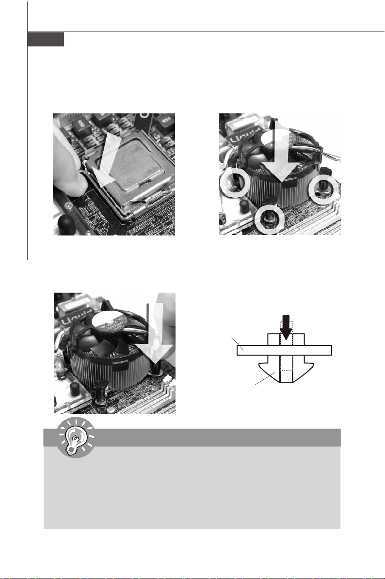
Carte mère MS-7392
9.Abaissez le levier sur le plateau de
chargement, puis sécuriser
l’ensemble avec le mécanisme de
rétention.
11.Appuyer sur le crochets pour attacher
le ventilateur. Puis effectuer une rotation des systèmes de rétention (voir
ventilateur pour le sens de rotation).
10. Aligner les trous de la carte avec
le ventilateur. Installer le ventilateur
dans les trous de la carte mčre.
12.Retourner la carte mère pour
s’assurer que le ventilateur est
correctement installé.
Carte mère
Interrupteur de
verrouillage
Crochet
Important
1. Lisez le statut du CPU dans le BIOS (Chapitre 3).
2. Quand le CPU n’est pas installé, toujours protectez vos picots de la douille
CPU avec le plastique de protection pour éviter tout dommage. (Montré dans
la Figure 1).
3. Les photos de la carte montrées dans cette section ne sont que pour une
démonstration de l’installation du CPU et son ventilateur. L’apparence de votre
carte mčre peut varier selon le modč le que vous achetez.
Fr-8
Page 74

Mémoire
Ces slots de DIMM sont destinés à installer les modules de mémoire.
Pour plus d’informations sur les composants compatibles, veuillez visiter http://global.
msi.com.tw/index.php?func=testreport
DDR2
240-pin, 1.8V
Simple-canal : All DIMMs dans le VERT
Doubles-canaux : Canal A dans le VERT ; Canal B dans le OR-
ANGE
64x2=128 pin 56x2=112 pin
A cause des limitations du chipset, il faut se référer au tableau suivant pour installer
les modules de mémoire afin d’activer le mode de doubles canaux ou celui de simple
canal.
Combinaison d’installation de mémoire
(SS : single side (une face), DS : double side(doubles face), X : mémoire
non installée)
DIMM1 DIMM2 DIMM3 DIMM4
Combinaison1 DS/SS X DS/SS X
Combinaison2 DS/SS X X DS/SS
Mode doubles-canaux
Combinaison3 X DS/SS DS/SS X
Combinaison4 X DS/SS X DS/SS
Combinaison5 SS SS SS SS
Combinaison1 DS/SS X X X
Combinaison2 X DS/SS X X
Combinaison3 X X DS/SS X
Combinaison4 X X X DS/SS
Mode simple-canal
Combinaison5 SS SS X X
Combinaison6 X X SS SS
Combinaison7 SS SS DS/SS X
Combinaison8 SS SS X DS/SS
Combinaison9 DS/SS X SS SS
Combinaison10 X DS/SS SS SS
Français
Fr-9
Page 75

Carte mère MS-7392
Installation des modules de mémoire
1. Le module de mémoire possède une seule encoche en son centre et ne s’adaptera
que s’il est orienté de la manière convenable.
2. Insérez le module de mémoire à la verticale dans le slot du DIMM. Poussez-le
ensuite jusqu’à l’extrémité dorée du module de mémoire, soit profondément insérée
dans le slot du DIMM. Le clip en plastique situe de chaque cote du module va se
fermer automatiquement.
Important
Vous pourrez à peine voir l’extrémité dorée si le module de mémoire est
correctement inséré dans le slot du DIMM.
3. Vérifiez manuellement si la barrette mémoire a été verrouillée en place par les clips
du slot DIMM sur les côtés.
Volt
Encoche
Important
-Les modules de mémoire DDR2 ne sont pas interchangeables par DDR et vice
versa. Vous devez toujours installer les modules de mémoire DDR2 dans les
slots DDR2 DIMM.
-En mode double-canaux, assurez-vous que vous installez les modules de mémoire
du même type et de la même densité dans les slots DIMM de canaux différents.
-Pour lance avec succès votre ordinateur, insérez tout d’abord les modules de
mémoire dans les DIMM1.
- A cause du développement de la ressource du chipset, la densité du système sera
détecté seulement jusqu’à 3+GB (non 4GB plein) quand chaque DIMM est installé
avec un module de mémoire de 1GB.
Fr-10
Page 76

Connecteur d’alimentation
Connecteur d’alimentation ATX 24-Pin : ATX1
Ce connecteur vous permet de connecter l’alimentation ATX 24-pin.
Pour cela, assurez-vous que la prise d’alimentation est bien
positionnée dans le bon sens et que les goupilles soient alignées.
Enfoncez alors la prise dans le connecteur.
Vous pourvez aussi utiliser un alimentation 20-pin selon vos besoins.
Veuillez brancher votre alimentation d’énergie avec le pin 1 et le pin
13 si vous voulez utiliser l’alimentation ATX 20-pin (Référez-vous à
l’image ą droite). Il y a aussi un infaillible plan sur les pins 11, 12, 23
et 24 afin d’éviter une faute installation.
Définition de pins
PIN SIGNAL
13 +3.3V
14 -12V
15 GND
16 PS-ON#
17 GND
18 GND
19 GND
20 Res
21 +5V
22 +5V
23 +5V
24 GND
ATX1
12
24
1
13
PIN SIGNAL
1 +3.3V
2 +3.3V
3 GND
4 +5V
5 GND
6 +5V
7 GND
8 PWR OK
9 5VSB
10 +12V
11 +12V
12 +3.3V
Connecteur d’alimentation ATX 12V : JPW1
Le connecteur d’alimentation de 12V JPW1 fournit l’alimentation au CPU.
pin 13
pin 12
Français
Définition de pins
3 4
1
JPW1
2
PIN SIGNAL
1 GND
2 GND
3 12V
4 12V
Important
1. Veuillez vous assurer que tous les connecteurs sont connectés aux correctes
alimentations ATX pour garantir une opération stable de la carte mère.
2. L’alimentation de 350 watts (et plus) est fortement recommandée pour la
stabilité du système.
Fr-11
Page 77

Carte mère MS-7392
Panneau arrière
Souris
Clavier
Port parallèle
Port sérial Port USB
Jack LAN
Line-In
Line-Out
Mic
RS-Out
CS-Out
SS-Out
Souris/Clavier
Le standard connecteur de souris/clavier DIN de PS/2® est pour une souris ou un
clavier de PS/2®.
Port Parallèle
Un port parallèle est un port standard d’imprimante qui supporte les modes Enhanced
Parallel Port (EPP) et Extended Capabilities Parallel Port (ECP).
Port Sérial
Ce connecteur de sérial est un port de communication de haute vitesse 16550A qui
envoie/reçoit 16 bytes FIFOs. Vous pouvez y attacher une souris de série ou autres
composants de série directement.
Port USB
Le port USB (Universal Serial Bus) sert à brancher des périphériques USB tel que le
clavier, la souris, ou d’autre périphériques compatibles USB.
Jack LAN
La prise standard RJ-45 LAN sert à la connexion au réseau local (Local Area Net-
work (LAN)). Vous pouvez y relier un câble de réseau.
Indicateur d’ activité
LED Couleur LED Statut Condition
Eteinte La connexion au réseau LAN n’est pas établie.
Gauche Jaune Allumée (stable) La connexion au réseau LAN est établie.
Allumée (plus brillant et
clignotante)
Vert Eteinte
Droite Allumée
Orange Allumée
L’ ordinateur communique avec un autre ordinateur
sur le réseau local LAN.
Un débit de 10 Mo/sec est sélectionné.
Un dé bit de 100 Mo/sec est sélectionné.
Un débit de 1000 Mo/sec est sélectionné.
Indicateur de lien
Fr-12
Page 78

Ports Audio
Ces connecteurs audio servent pour les périphériques audio. Vous pouvez différencier
la couleur des prises audio pour obtenir divers effets sonores.
Ligne-In (Bleu) - Ligne In, est utilisée pour un appareil de CD externe,
cassette ou d’autre périphériques.
Ligne-Out (Vert) - Ligne Out, est destiné aux haut-parleurs ou aux
casques d’écoute.
Mic (Rose) - Mic In est un connecteur pour les microphones.
RS-Out (Noir) - Rear-Surround Out en mode de canal 4/ 5.1/ 7.1.
CS-Out (Orange) - Center/ Subwoofer out en mode de canal 5.1/ 7.1.
SS-Out (Gris) - Side-Surround Out en mode de canal 7.1.
Français
Fr-13
Page 79

Carte mère MS-7392
Connecteurs
Connecteur Floppy Disk Drive : FDD1
Ce connecteur supporte le lecteur de disquette de 360KB, 720KB, 1.2MB, 1.44MB ou
2.88MB.
FDD1
Connecteur IDE : IDE1
Ce connecteur supporte les lecteurs de disque dur IDE, lecteurs optiques de disque
et d’autre périphériques IDE.
IDE1
Important
Si vous installez deux périphériques IDE sur le même câble, vous devez
configurer les périphériques séparément en mode Master/ Slave par les
cavaliers de configuration. Référez-vous aux documentations des
périphériques de IDE offertes par votre vendeur pour les instructions de
configurations des cavaliers.
Fr-14
Page 80

Connecteur Sérial ATA : SATA1/ SATA2/ SATA3/ SATA4
Ce connecteur est un port d’interface de série ATA haut débit. Chaque connecteur
peut źtre relié ą un appareil de série ATA.
SATA4SATA3
SATA2SATA1
Important
Veuillez ne pas plier le câble de série ATA à 90°. Autrement des pertes de
données pourraient se produire pendant la transmission.
Connecteur d’alimentation du ventilateur : CPUFAN1/ SYSFAN1/
SYSFAN2 / SYSFAN3
Les connecteurs de courant du ventilateur supportent le ventilateur de
refroidissement du système avec +12V. Lors du branchement des fils aux
connecteurs, faites toujours en sorte que le fil rouge soit le fil positif devant être relié
au connecteur +12V; et que le fil noir soit le fil de mise à la terre devant être relié au
connecteur de mise à la terre GND. Si la carte mère est équipée d’un jeu de puces
intégré pour moniteur de matériel de système, vous devrez utiliser un ventilateur
spécial pourvu d’un capteur de vitesse afin de contrôler le ventilateur de l’unité
centrale.
SENSOR
SENS OR
+12V
GND
Control
+12V
GND
+1 2V
SE NS OR
GND
SYSFAN1
CPUFAN1
SYSFAN3
SYSFAN2
Important
1.Veuillez consulter les ventilateurs d’unité centrale recommandés sur les sites
officiels des fabricants de processeurs ou bien consultez votre revendeur
pour obtenir des informations sur le ventilateur de refroidissement adapté à
votre unité centrale.
2. Ventilateur avec 3 ou 4 broches sont tous deux disponibles pour CPUFAN1.
3. CPUFAN1 supporte le contrôle du ventilateur. Vous pouvez l’installer dans le
moniteur H/W du réglage BIOS. Vous pouvez installer l’unité centre dual core
qui contrôlera automatiquement la vitesse du ventilateur du CPU selon la
température actuelle du CPU.
Français
Fr-15
Page 81

Carte mère MS-7392
Connecteur Châssis Intrusion : JCI1
Ce connecteur est connecté à un câble châssis intrusion switch. Si le châssis est
ouvert, le switch en informera le système, qui enregistera ce statut et affichera un
écran d’alerte. Pour effacer ce message d’alerte, vous devez entrer dans le BIOS et
désactiver l’alerte.
C
I
N
G
T
N
R
D
U
2
1
JCI1
Connecteur CD-In : JCD1
Ce connecteur est fournit pour un audio externe d’entrer.
GND
L
R
JCD1
Connecteur du Module TPM : JTPM1
Ce connecteur est rélié à TPM (Trusted Platform Module) Module (optionnel). Veuillez
vous référer au manuel de TPM plat-forme de sécurité pour plus de détails et
d’utilisations.
13
14
JTPM1
Pin Signal Description Pin Signal Description
1 LCLK LPC clock 2 3V dual/3V_STB 3V dual or 3V standby power
3 LRST# LPC reset 4 VCC3 3.3V power
5 LAD0 LPC address & data pin0 6 SIRQ Serial IRQ
7 LAD1 LPC address & data pin1 8 VCC5 5V power
9 LAD2 LPC address & data pin2 10 KEY No pin
11 LAD3 LPC address & data pin3 12 GND Ground
13 LFRAME# LPC Frame 14 GND Ground
1
2
Fr-16
Page 82
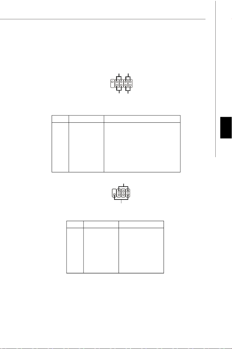
Connecteurs du panneau avant : JFP1/ JFP2
Ces connecteurs sont fournis pour la connecxion électrique aux interrupteus et
LEDs du panneau avant. Il est conforme au guide de conception de la connectivité
Entrée/sortie du panneau avant Intel®.
JFP1
Définition des pins pour JFP1
PIN SIGNAL DESCRIPTION
1 HD_LED + Hard disk LED pull-up
2 FP PWR/SLP MSG LED pull-up
3 HD_LED - Hard disk active LED
4 FP PWR/SLP MSG LED pull-up
5 RST_SW - Reset Switch low reference pull-down to GND
6 PWR_SW - Power Switch high reference pull-down to GND
7 RST_SW + Reset Switch high reference pull-up
8 PWR_SW + Power Switch low reference pull-up
9 RSVD_DNU Reserved. Do not use.
9
10
Reset
Switch
-
+
-
Power
Switch
Power LED
HDD
LED
-
+
1
2
+
Power
LED
Français
JFP2
7
8
-
+
Speaker
1
2
+
-
Dé finition des pins pour JFP2
PIN SIGNAL DESCRIPTION
1 GND Ground
2 SPK- Speaker3 SLED Suspend LED
4 BUZ+ Buzzer+
5 PLED Power LED
6 BUZ- Buzzer7 NC No connection
8 SPK+ Speaker+
Fr-17
Page 83

Carte mère MS-7392
Connecteur audio panneau avant : JAUD1
Ce connecteur vous permet de connecter un audio sur le panneau avant. Il est
conforme au guide de conception de la connectivité Entrée/sortie du panneau avant
Intel®.
9
10
1
2
JAUD1
Définition de pins pour HD Audio
PIN SIGNAL DESCRIPTION
1 MIC_L Microphone - Left channel
2 GND Ground
3 MIC_R Microphone - Right channel
4 PRESENCE# Active low signal-signals BIOS that a High Definition Audio dongle
5 LINE out_R Analog Port - Right channel
6 MIC_JD Jack detection return from front panel microphone JACK1
7 Front_JD Jack detection sense line from the High Definition Audio CODEC
8 NC No control
9 LINE out_L Analog Port - Left channel
10 LINEout_JD Jack detection return from front panel JACK2
is connected to the analog header. PRESENCE# = 0 when a
High Definition Audio dongle is connected
jack detection resistor network
Définition de pins pour AC’97 Audio
PIN SIGNAL DESCRIPTION
1 MIC Microphone input signal
2 GND Ground
3 MIC_PWR Microphone power
4 NC No Control
5 LINE out_R Right channel audio signal to front panel
6 NC No Control
7 NC No Control
8 Key No pin
9 LINE out_L Left channel audio signal to front panel
10 NC No Control
Fr-18
Page 84

Connecteur IEEE1394 : J1394_1 (optionnel)
Ce connecteur vous permet de relier un appareil IEEE139 via un support optionnel
IEEE1394.
Définition de pins
PIN SIGNAL PIN SIGNAL
2
1
J1394_1
9
10
1 TPA+ 2 TPA3 Ground 4 Ground
5 TPB+ 6 TPB7 Cable power 8 Cable power
9 Key (no pin) 10 Ground
Support IEEE1394
(optionnel)
Connecteur S/PDIF-Out : JSP1
Ce connecteur est utilisé pour relier à l’interface S/PDIF (Sony & Philips Digital Interconnect Format) de la transmission audio numérique.
Français
GND
SPDIF-out
VCC
JSP1
Support S/PDIF
(optionnel)
Fr-19
Page 85

Carte mère MS-7392
Connecteur USB avant : JUSB1/ JUSB2
Ce connecteur est conforme au guide de conception de la connectivité Entrée/sortie
du panneau avant Intel®, il est idéal pour relier les périphériques d’interface USB à
haut débit tels les disques durs externes, les appareils photo numériques,
les lecteurs MP3, les imprimantes, les modems et les appareils similaires.
Définition de pins
2 10
1
JUSB1
JUSB2
9
PIN SIGNAL PIN SIGNAL
1 VCC 2 VCC
3 USB0- 4 USB15 USB0+ 6 USB1+
7 GND 8 GND
9 Key (no pin) 10 USBOC
Support USB 2.0
(Optional)
Important
Notez que les broches de VCC (Connexion de voie virtuelle) et GND (terre)
doivent źtre branchées correctement afin d’éviter tout dommage possible.
Fr-20
Page 86

Cavaliers
Cavalier d’effacement du CMOS : JBAT1
Il y a un CMOS RAM intégré, qui possède un bloc d’alimentation alimenté par une
batterie externe, destiné à conserver les données de configuration du système.
Avec le CMOS RAM, le système peut lancer automatiquement le système d’exploitation
chaque fois qu’il est allumé. Si vous souhaitez effacer la configuration du système,
réglez le cavalier de maničre ą effacer les données.
JBAT1
1
1 3
conserver les données Effacer les données
1 3
Important
Vous pouvez effacer le CMOS en raccourcissant 2-3 broches quand le système
est éteint. Retournez ensuite en position 1-2 broches. Evitez d’effacer le CMOS
pendant que le système est allumé; cela endommagerait la carte mère.
Cavalier du FSB d’overclocking des matériaux : JFSB1/ JFSB2
Vous pouvez overclocker le FSB afin d’augmenter la fréquence du processeur en
changeant l’interrupteur OC_SW1. Suivez les instructions suivantes pour régler le
FSB.
JFSB1
JFSB2
1 3
1 3
200 MHz
(Défaut)
1 3
266 MHz
1 3
333 MHz
Important
Français
1. Veuillez vous assurer d’éteindre le système avant de changer le cavalier.
2. Veuillez régler le cavalier en défaut OC si vous avez besoin de supporter
le FSB400 CPU.
Fr-21
Page 87

Carte mère MS-7392
Slots
Slot PCI (Peripheral Component Interconnect) Express
Le slot PCI Express supporte la carte d’expension de l’interface du PCI Express.
Le slot PCI Express x 16 supporte un taux de transfert jusqu’à 4.0 GB/s.
Le slot PCI Express x 1 supporte un taux de transfert jusqu’à 250 MB/s.
Slot PCI Express x16
Slot PCI Express x 1
Slot PCI (Peripheral Component Interconnect)
Le slot PCI supporte la carte LAN, la carte SCSI, la carte USB et d’autres cartes
ajoutées qui sont compatibles avec les spécifications de PCI.
Slot 32-bit PCI
Important
Lorsque vous ajoutez ou retirez une carte d’extension, assurez-vous que le PC
n’est pas relié au secteur. Lisez la documentation pour faire les configurations
nécessaires du matériel ou du logiciel de la carte d’extension, tels que cavaliers,
commutateurs ou la configuration du BIOS.
Chemins de revendication d’interruption de PCI
IRQ est l’abréviation de “interrupt request line”. Les IRQ sont des lignes de matériel
sur lesquelles les périphériques peuvent émettre des signaux d’interruption au microprocesseur. Les picots de PCI IRQ sont typiquement connectés aux picots de bus PCI
comme suivant :
Order 1 Order 2 Order 3 Order 4
PCI Slot 1 INT A# INT B# INT C# INT D#
PCI Slot 2 INT B# INT C# INT D# INT A#
PCI Slot 3 INT C# INT D# INT A# INT B#
Fr-22
Page 88

Réglages BIOS
Ce chapitre donne des informations concernant le programme de réglage de BIOS et
vous permet de configurer le système pour obtenir des performances d’utilisation
optimum. Vous aurez peut-être besoin de lancer le programme de réglage quand :
* Un message d’erreur apparaît sur l’écran pendant le démarrage du système, qui
vous demande de lancer SETUP (Réglage).
* Vous souhaitez changer les réglages par défaut des fonctions personnalisées.
Important
1.Les objets situés sous chaque catégorie BIOS décrits dans ce chapitre
sont en cours de mise à jour continue pour améliorer les performances du
système. C'est pourquoi il est possible que la description soit légèrement
différente du BIOS le plus récent, et ne doit servir que comme référence.
2.Au redémarrage, la première ligne qui apparaît après le compte de la mémoire,
est la version BIOS. Elle est généralement sous la forme :
A7392IMS V2.0 071307 où :
Le premier caractère se rapporte au fabricant du BIOS : A = AMI, W = AWARD,
et P = PHOENIX.
Les caratères du second au cinquième caractère se rapportent au numéro de
modèle.
Le sixičme caractčre se rapporte au jue de puces : I = Intel, N = nVidia, and
V = VIA.
Les septième et huitième caractère se rapportent au client : MS = all standard
customers (tous les clients standards).
V2.0 se rapporte à la version de BIOS.
071307 se rapporte à la date à laquelle est sortie ce BIOS.
Français
Fr-23
Page 89

Carte mère MS-7392
Réglages d’Entrée
Allumez l'ordinateur et le système lancera le processus POST (Test automatique
d'allumage). Lorsque le message ci-dessous apparaît à l'écran, appuyez sur la touche <DEL> pour entrer dans les réglages.
Appuez sur DEL pour entrer dans SETUP
Si le message disparaît avant que vous ne répondiez et que vous souhaitez encore
entrer dans Setup (Réglages), redémarrez le système en OFF (éteignant) puis en On
(rallumant) en appuyant sur le bouton RESET (Réinitialiser). Vous pouvez également
redémarrer le système en appuyant simultanément sur les touches <Ctrl>, <Alt>, et
<Delete>.
Obtenir de l’aide
Après être entré dans le menu de Réglage, le premier menu que vous verrez apparaître
sera le menu principal.
Menu principal
Le menu principal établit la liste des fonctions de réglage que vous pouvez modifier.
Vous pouvez utiliser les touches de flèche (¡ô¡õ ) pour sélectionner l'objet. La de-
scription en ligne des fonctions de réglages illuminées est affichée au bas de l'écran.
Sous-Menu
Si vous un symbole de pointeur droit (comme indiqué sur la
vue de droite) apparaît sur la gauche de certains champs,
cela signifie qu'un sous-menu peut être lancé à partir de ce
champ. Un sous-menu contient des options supplémentaires
pour un paramètre de champ. Vous pouvez utiliser les touches
de flèche (¡ô¡õ ) pour illuminer le champ puis appuyez sur <Enter> (Entrer) pour faire
apparaître le sous-menu. Vous pourrez alors utiliser les touches de commande pour
saisir des valeurs et vous déplacer d'un champ à un autre à l'intérieur d'un sous-
menu. Si vous souhaitez revenir au menu principal, appuyez juste sur <Esc>.
Aide générale <F1>
Le programme de réglages BIOS fournit un écran d'aide générale. Vous pouvez faire
sortir cet écran à partir de n'importe quel menu en appuyant simplement sur <F1>.
L'écran d'aide donne une liste des touches appropriées à utiliser et les sélections
possibles pour l'objet illuminé. Appuyez sur <Esc> pour quitter l'écran d'aide.
Fr-24
Page 90

Menu principal
Une fois entré dans l’unité de réglages AMI® ou AWARD® BIOS CMOS, le Menu principal appaît sur l’écran. Le Menu Principal vous permet de sélectionner de dix foncions
de réglage et deux choix de sortie. Utilisez les touches de flèche pour sélectionner
parmi les objets et appuyez sur <Enter> pour accepter ou entrer dans le sous-menu.
Standard CMOS Features (Fonctions CMOS standard)
Utilisez ce menu pour les configurations du système de base, tel que l’heure, la date.
Advanced BIOS Features (Fonctions BIOS avancées)
Utilisez ce menu pour régler les objets des fonctions améliorées spéciales.
Integrated Peripherals (Périphériques intégrés)
Utilisez ce menu pour définir vos régléges des périphériques intégrés.
Power Management Features (Fonctions de la gestion de l’énergie)
Utilisez ce menu pour définir vos réglages de la gesion de l’énergie.
PnP/PCI Configurations (Configurations PnP/PCI)
Cette entrée appataîtra si votre système supporte PnP/PCI.
H/W Monitor (Moniteur H/W)
Cette entrée indique l’état de santé de votre PC.
Frequency/Voltage Control (Contrôle de la fréquence/ du voltage)
Utilisez ce menu afin de spécifier vos réglages pour le contrôle de la fréquence/ du
voltage et l’overclocking.
Load Fail-Safe Defaults (Défauts de sécurité de chargement intégrée)
Utilisez ce menu pour charger les valeur par défauts réglées par le vendeur de BIOS
afin de garantir la stabilité des performances du système.
Load Optimized Defaults (Chargement des réglages par défaut optimisés)
Utilisez ce menu pour charger les valeurs par défaut réglées par le fabricant de la
carte mère spécifiquement pour obtenir des performances optimales de la carte
mère.
BIOS Setting Password (Mot de passe de réglage BIOS)
Utilisez ce menu pour régler le mot de passe du BIOS.
Save & Exit Setup (Sauvegarder et quitter les réglages)
Sauvegardez les changements apportés au CMOS puis quittez les réglages.
Exit Without Saving (Quitter sans sauvegarder)
Abandonnez tous les changements et quittez les réglages.
Français
Fr-25
Page 91

Carte mère MS-7392
Quand vous entrez dans l’unité de réglages BIOS, suivez les procédures
suivantes pour l’utilisation générale.
1. Load Optimized Defaults (chargement des réglages par défaut optimisés)
: Utilisez les touches de contrôle (↑↓) afin de surligner le domaine Load
Optimized Defaults et appuyez sur <Enter> , le message suivant apparaîtra :
Choisir [Ok] et appuyer sur Enter chargera les valeurs défauts de BIOS pour un
système minimal plus stable.
2. Setup Date/ Time (Réglage de l’heure et de la date) : Choisissez Standard
CMOS Features et appuyez sur <Enter> afin d’entrer dans le menu Standard
CMOS Features. Ajustez la date et l’heure.
3. Save & Exit Setup (Sauvegarder et quitter les réglages) : Utilisez les
touches de contrôle (↑↓) afin de surligner le domaine de Save & Exit Setup et
appuyez sur <Enter> , le message suivant apparaîtra :
Choisir [Ok] et appuyer sur Enter afin de sauvegarder les configurations et l’unité
de réglages de quitter BIOS.
Important
Les configurations préc édantes ne sont que pour l’utilisation générale. Si
vous avez besoin de réglages détaillés du BIOS, veuillez vous référer au
manuel de l’édition anglaise sur la page d’internet de MSI.
Fr-26
Page 92

4. Introduction du moniteur H/W
Châssis Intrusion
Ce domaine active ou désactive la fonction de l’enregistrement du statut de châssis
intrusion et de l’émission d’un message d’alarme si le châssis intrusion est ouvert.
Régrlez ce domaine en [Reset] pour effacer ce message d’alarme. Les réglages de
ce domaine retourne automatiquement en [Enabled] après.
CPU Smart FAN Target
La carte mère fournit la fonction Smart Fan qui contrôle automatiquement la vitesse
du ventilateur selon la température actuelle du CPU afin de le tenir dans le cadre
spécifique. Vous pouvez choisir un valeur de cadre du ventilateur ici. Si la température
actuelle du ventilateur du CPU atteint à ce valeur, la fonction Smart Fan sera activée.
Elle fournit plusieures sections qui accélèrera pour baisser automatiquement la
température.
CPU Min.FAN Speed (%)
Ce domaine sert ą régler la vitesse minimum du ventilateur du CPU.
SYS FAN1 Control
Ce domaine vous permet de déterminer si le ventilateur du système, connecté à
SYSFAN1, fonctionnera ou pas quand le système est activé.
Français
PC Health Status
CPU/ System Temperature, CPU FAN/ SYS FAN1/ 2 Speed, CPU Vcore, 3.3V,,
5V, 12V
Ces articles montrent les statuts actuels de tous les périphériques/ composants
surveillés du matériaux tels que le voltage du CPU, la température et la vitesse du
ventilateur.
Fr-27
Page 93

Carte mère MS-7392
Information de Logiciel
Sortez le pilote/ Service du CD, qui est inclus dans le paquet de la carte mère et
placez-le dans le CD-ROM.L’installation va automatiquement se déclencher, cliquez
sur le pilote ou sur l’usage et suivez le pop-up de l’écran pour accomplir l’installation.
Le pilote/Service CD contient :
Menu de pilote – Il montre les pilotes disponibles. Installez le pilote si vous le
souhaitez pour activer le dispositif.
Menu de services – Il montre les applications logicielles supportées par la carte mère.
Menu du site Web – Il vous indique les sites webs utiles.
Important
Veuillez consulter le site Web de MSI pour obtenir les derniers pilotes et
BIOS pour améliorer l’exécution du systčme de votre ordinateur.
Fr-28
Page 94

Серия G31P Neo2
Руководство
пользователя
Русский
Русский
Ru-1
Page 95

MS-7392 Системная плата
Характеристики
Процессоры
- Процессоры Intel® CoreTM2 Quad, CoreTM2 Duo, Pentium® E2XXX
и Celeron® 4XX в конструктиве LGA775
(Для получения самой новой информации о CPU, посетите
сайт http://global.msi.com.tw/index.php?func=cpuform)
FSB
- 1333/ 1066/ 800 МГц
Чипсет
- Северный мост: Intel® P31/ G31
- Южный мост: Intel® ICH7R/ ICH7
Память
- DDR2 800/ 667 SDRAM (4GB Max)
- 4 слота DDR2 DIMM (240конт/ 1.8V)
(За дополнительной информацией о совместимых
компонентах посетите сайт http://global.msi.com.tw/index.php?
func=testreport)
LAN
- Поддержка PCI Express LAN 10/ 100/ 1000 Fast Ethernet на
чипсете Realtek® RTL8111C/ RTL8111B (опционально)
Ru-2
IEEE 1394 (опционально)
- Интегрированный чипсет VIA® VT6308P
- Скорость передачи данных до 400 Мб/с
Аудио
- Интегрированный чипсет Realtek® ALC888
- 8-канальное аудио с гибким переназначением разъемов
- Совместимость со спецификацией Azalia 1.0
- Ńīāģåńņčģīńņü ńī ńļåöčō čźąöčåé Microsoft
®
Windows
VistaTM Premium
IDE
- 1 порт IDE на чипсете Intel® ICH7R/ ICH7
- Поддержка режимов Ultra DMA 66/ 100
- Поддержка режимов работы PIO и Bus Master
SATA
- 4 порта SATA II на чипсете Intel® ICH7R/ ICH7
- Поддержка 4-х устройств SATA
- Поддержка скорости передачи данных до 3Гб/с
®
Page 96

RAID
- Поддержка режимов RAID 0/ 1/ 0+1/ 5 на чипсете Intel® ICH7R
Флоппи
- 1 флоппи порт
- Поддержка 1 FDD с 360KB, 720KB, 1.2MB, 1.44MB и 2.88MB
Коннекторы
Задней панели
- 1 PS/2 порт мыши
- 1 PS/2 порт клавиатуры
- 1 параллельный порт
- 1 последовательный порт
- 1 разъем LAN
- 4 порта USB
- 6 звуковых разъемов
Разъемы, установленные на плате
- 2 разъема USB
- 1 разъем CD-in
- 1 разъем S/PDIF-out
- 1 разъем для подключения аудио на передней панели
- 1 разъем датчика открывания корпуса
- 1 разъем 1394 (опционально)
- 1 разъем JTPM модуля
Слоты
- 1 слот PCI Express x16
- 2 слота PCI Express x1
- 3 слота PCI (поддержка интерфейса PCI шины с питанием 3.
3V/ 5V)
Русский
Форм Фактор
- ATX (30.5см X 23.6см)
Крепление
- 6 отверстий для крепления
Ru-3
Page 97

MS-7392 Системная плата
Руководство по размещению компонентов
Back Panel,
Ru-12
JFSB1~2,
Ru-21
SYSFAN2,
Ru-15
PCIE Slots,
Ru-22
JBAT1,
Ru-21
PCI Slots,
Ru-22
JAUD1,
Ru-18
JPW1,
Ru-11
JCD1,
Ru-16
JSP1,
Ru-19
CPU,
Ru-5
FDD1,
Ru-14
J1394_1,
Ru-19
(опционально)
CPUFAN1,
Ru-15
JUSB1~2,
Ru-20
SYSFAN3,
Ru-15
Memory,
Ru-9
ATX1,
Ru-11
JCI1,
Ru-16
SYSFAN1,
Ru-15
SATA1~4,
Ru-15
JTPM1,
Ru-16
IDE1,
Ru-14
JFP1~2,
Ru-17
Ru-4
Page 98

CPU (Центральный процессор)
При установке CPU, чтобы уберечь процессор от перегрева, убедитесь
в том, что процессорный кулер установлен. Если у вас нет
процессорного кулера, пожалуйста, свяжитесь с дилером с целью
приобретения и его установки до того, как включите компьютер .
Самую последнюю информацию о CPU можно получить на сайте http://global.
msi.com.tw/index.php?func=cpuform
Внимание
Перегрев
Перегрев может серьезно повредить центральный процессор и систему.
Чтобы уберечь процессор от перегрева, убедитесь в том, что
процессорный кулер работает нормально. Чтобы увеличить
теплорассеивание, убедитесь в том, что нанесен слой теплопроводящей
пасты (или теплопроводящей ленты) между процессором и радиатором.
Замена CPU
При замене CPU, во избежание его повреждения, обязательно отключите
источник питания или выньте вилку блока питания из розетки.
Разгон
Эта системная плата поддерживает “разгон”. Однако, убедитесь, что
компоненты системы способны работать в таких нестандартных
режимах при разгоне. Не рекомендуется использовать продукт в режимах,
не соответствующих указанным в спецификациях. Мы не гарантируем
защиту от повреждений и рисков, вызванных неправильной
эксплуатацией и установкой параметров с превышением
характеристик.
Русский
Введения установки процессора LGA 775
Вид процессора со стороны
контактной панели LGA 775.
Alignment Key Alignment Key
Yellow triangle is the Pin 1 indicator
Внешний вид процессора.
Чтобы увеличить
теплорассеивание, убедитесь в
том, что нанесен слой
теплопроводящей пасты.
Yellow triangle is the Pin 1 indicator
Ru-5
Page 99

MS-7392 Системная плата
Установка процессора и вентилятора
Во избежание перегрева при работе обязательно установите вентилятор
процессора. Одновременно, чтобы увеличить теплорассеивание, убедитесь в
том, что нанесен слой теплопроводящей пасты на процессоре при установке
вентилятора. Следуйте нижеследующим указаниям для правильной установки.
Неправильная установка приведет повреждения процессора & системной платы.
1. Разъем процессора закрыт пластиковой
крышкой, которая защищает контакты
разъема от повреждений. При отсутствии
процессора, необходимо всегда
закрывать разъем пластиковой крышкой
для защиты его контактов.
2. Снимите крышку, подняв ее с
одной стороны (как показывает
стрелка).
3. Откроются контакты разъема.
4. Потяните за рычаг крепления.
Внимание
1. Перед включением системы убедитесь, что вентилятор правильно
установлен.
2. Во избежание повреждений не прикасайтесь к контактам сокета
процессора.
3. Наличие нижней защитной крышки для процессора зависит от
комплекта поставки.
Ru-6
Page 100

5. Поднимите рычаг и откройте
металлическую крышку для
установки процессора.
6. Убедившись в правильной
ориентации процессора,
положите процессор в разъем.
О братите внимание, что
выемки на процессоре должны
соответствовать выступам на
процессорном разъеме.
alignment
key
Русский
7. В изуально проверьте
правильность установки
процессора в разъем. Если
процессор установлен
неправильно, то выньте
процессор и переустановите.
8. Опустите маталлическую
крышку механизма крепления.
Ru-7
 Loading...