

Page 1
G31M4 Series
MS-7527 (V1.X) Mainboard
G52-75271X2
i
Page 2

Copyright Notice
The material in this document is the intellectual property of MICRO-STAR
INTERNATIONAL. We take every care in the preparation of this document, but no
guarantee is given as to the correctness of its contents. Our products are under
continual improvement and we reserve the right to make changes without notice.
Trademarks
All trademarks are the properties of their respective owners.
NVIDIA, the NVIDIA logo, DualNet, and nForce are registered trademarks or trade-
marks of NVIDIA Corporation in the United States and/or other countries.
AMD, Athlon™, Athlon™ XP, Thoroughbred™, and Duron™ are registered trade-
marks of AMD Corporation.
Intel® and Pentium® are registered trademarks of Intel Corporation.
PS/2 and OS®/2 are registered trademarks of International Business Machines
Corporation.
Windows® 2000/NT/XP/Vista are registered trademarks of Microsoft Corporation.
Netware® is a registered trademark of Novell, Inc.
Award® is a registered trademark of Phoenix Technologies Ltd.
AMI® is a registered trademark of American Megatrends Inc.
Revision History
Revision Revision History Date
V1.0 First release August 2008
Technical Support
If a problem arises with your system and no solution can be obtained from the user’s
manual, please contact your place of purchase or local distributor. Alternatively,
please try the following help resources for further guidance.
Visit the MSI website for FAQ, technical guide, BIOS updates, driver updates,
and other information: http://global.msi.com.tw/index.php?
func=service
Contact our technical staff at: http://ocss.msi.com.tw
ii
Page 3
Safety Instructions
1. Always read the safety instructions carefully.
2. Keep this User’s Manual for future reference.
3. Keep this equipment away from humidity.
4. Lay this equipment on a reliable flat surface before setting it up.
5. The openings on the enclosure are for air convection hence protects the equipment from overheating. DO NOT COVER THE OPENINGS.
6. Make sure the voltage of the power source and adjust properly 110/220V before connecting the equipment to the power inlet.
7. Place the power cord such a way that people can not step on it. Do not place
anything over the power cord.
8. Always Unplug the Power Cord before inserting any add-on card or module.
9. All cautions and warnings on the equipment should be noted.
10. Never pour any liquid into the opening that could damage or cause electrical
shock.
11. If any of the following situations arises, get the equipment checked by a service
personnel:
† The power cord or plug is damaged.
† Liquid has penetrated into the equipment.
† The equipment has been exposed to moisture.
† The equipment has not work well or you can not get it work according to
User’s Manual.
† The equipment has dropped and damaged.
† The equipment has obvious sign of breakage.
12. DO NOT LEAVE THIS EQUIPMENT IN AN ENVIRONMENT UNCONDITIONED, STORAGE TEMPERATURE ABOVE 600 C (1400F), IT MAY DAMAGE THE EQUIPMENT.
CAUTION: Danger of explosion if battery is incorrectly replaced.
Replace only with the same or equivalent type recommended by the
manufacturer.
iii
Page 4

FCC-B Radio Frequency Interference Statement
This equipment has been
tested and found to comply
with the limits for a Class B
digital device, pursuant to Part
15 of the FCC Rules. These limits are designed to provide reasonable protection
against harmful interference in a residential installation. This equipment generates,
uses and can radiate radio frequency energy and, if not installed and used in accor-
dance with the instructions, may cause harmful interference to radio communications.
However, there is no guarantee that interference will not occur in a particular
installation. If this equipment does cause harmful interference to radio or television
reception, which can be determined by turning the equipment off and on, the user is
encouraged to try to correct the interference by one or more of the measures listed
below.
† Reorient or relocate the receiving antenna.
† Increase the separation between the equipment and receiver.
† Connect the equipment into an outlet on a circuit different from that to
which the receiver is connected.
† Consult the dealer or an experienced radio/television technician for help.
Notice 1
The changes or modifications not expressly approved by the party responsible for
compliance could void the user’s authority to operate the equipment.
Notice 2
Shielded interface cables and A.C. power cord, if any, must be used in order to
comply with the emission limits.
VOIR LA NOTICE D ’INSTALLATION AVANT DE RACCORDER AU RESEAU.
Micro-Star International
MS-7527
This device complies with Part 15 of the FCC Rules. Operation is subject to the
following two conditions:
(1) this device may not cause harmful interference, and
(2) this device must accept any interference received, including interference that
may cause undesired operation.
iv
Page 5
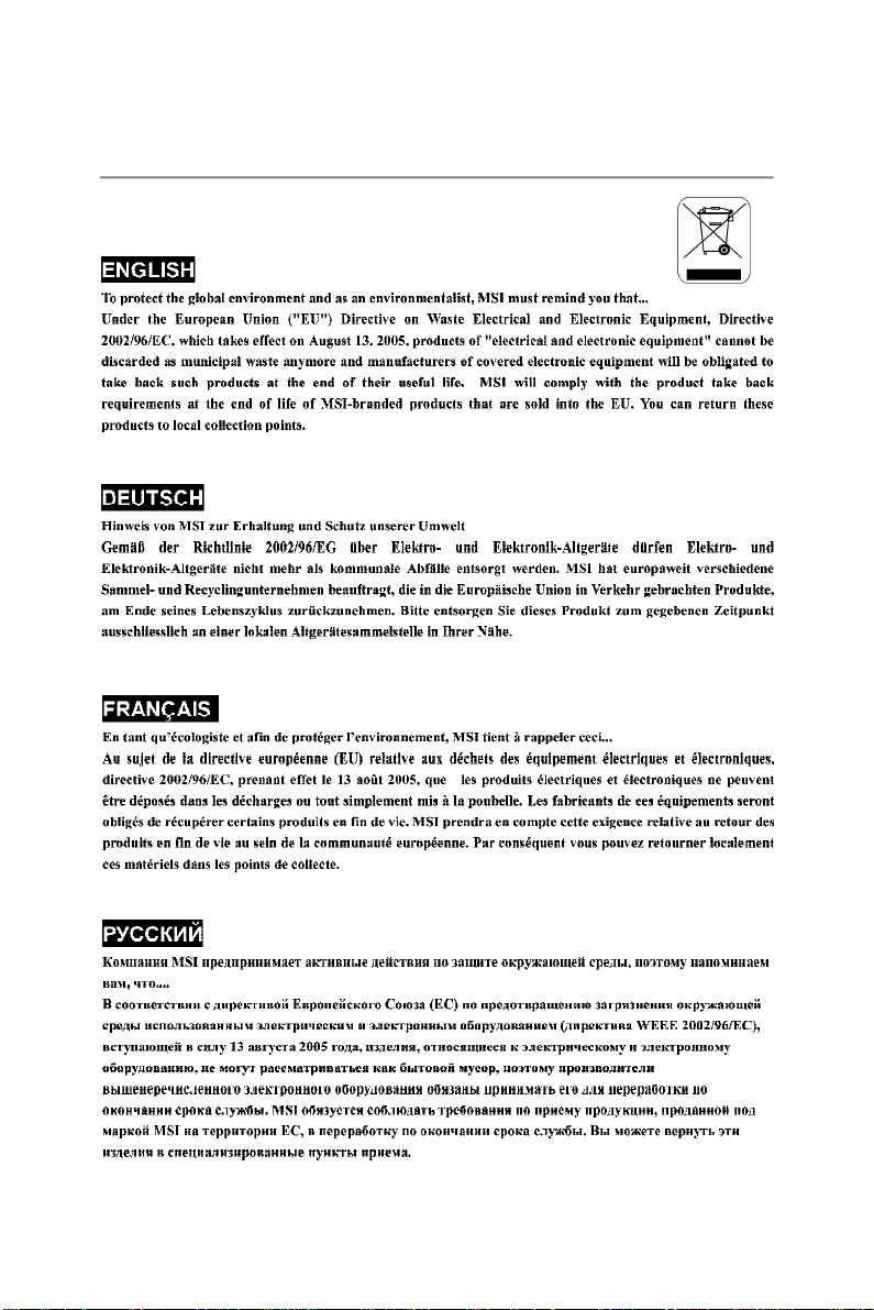
WEEE (Waste Electrical and Electronic Equipment) Statement
v
Page 6
vi
Page 7
vii
Page 8

CONTENTS
Copyright Notice.........................................................................................................ii
Trademarks..................................................................................................................ii
Revision History.........................................................................................................ii
Technical Support......................................................................................................ii
Safety Instructions...................................................................................................iii
FCC-B Radio Frequency Interference Statement.............................................iv
WEEE (Waste Electrical and Electronic Equipment) Statement.......................v
English......................................................................................................................En-1
Specifications....................................................................................................En-2
Central Processing Unit: CPU...........................................................................En-5
Memory...............................................................................................................En-7
Connectors, Jumpers, Slots.............................................................................En-9
Back Panel........................................................................................................En-16
BIOS Setup.......................................................................................................En-18
Software Information......................................................................................En-25
Deutsch....................................................................................................................De-1
Spezifikationen..................................................................................................De-2
Hauptprozessor: CPU.......................................................................................De-5
Speicher.............................................................................................................De-7
Anschlüsse, Steckbrücken und Slots.............................................................De-9
Hinteres Anschlusspaneel.............................................................................De-16
BIOS Setup.......................................................................................................De-18
Software-Information......................................................................................De-25
Français.....................................................................................................................Fr-1
Spécificités.........................................................................................................Fr-2
Central Processing Unit: CPU............................................................................Fr-5
Mémoire...............................................................................................................Fr-7
Connecteurs, Cavaliers, Slots..........................................................................Fr-9
Panneau Arrière...............................................................................................Fr-16
Configuration du BIOS......................................................................................Fr-18
Information de Logiciel.....................................................................................Fr-25
Русский ....................................................................................................................Ru-1
Характеристики ...............................................................................................Ru-2
Центральный процессор (CPU).....................................................................Ru-5
Память ..............................................................................................................Ru-7
Коннекторы, перемычки, разъемы..............................................................Ru-9
Задняя панель ...............................................................................................Ru-16
Настройка BIOS..............................................................................................Ru-18
Сведения о программном обеспечении ...................................................Ru-25
viii
Page 9

G31M4
User’s Guide
Engli sh
English
En-1
Page 10
MS-7527 Mainboard
Specifications
Processor Support
- Intel® Core2 Duo/ Pentium D/ Pentium 4 / Celeron D Prescott
LGA775 processors in LGA775 package.
- Supports 4-pin CPU Fan Pin-Header with Fan Speed Control.
(For the latest information about CPU, please visit http://global.msi.
com.tw/index.php?func=cpuform)
Supported FSB
- 800/1066/1333 MHz
Chipset
- North Bridge: Intel® G31 chipset
- South Bridge: Intel® ICH7 chipset
Memory Support
- DDR2 667/800 SDRAM (4GB Max)
- 4 DDR2 DIMMs
(For more information on compatible components, please visit http:/
/global.msi.com.tw/index.php?func=testreport)
LAN (optional)
- Supports Realtek® RTL8111C 10/100/1000 Mb/s
- Supports Realtek® RTL8101E 10/100 Mb/s (optional)
- Compliance with PCI 2.2
- Supports ACPI Power Management
En-2
Audio
- Chip integrated by Realtek® ALC888
- Flexible 8-channel audio with jack sensing
- Compliant with vista premium
IEEE 1394 (optional)
- Chip integrated by JMicron 381
- Transfer rate is up to 400Mbps
IDE
- 1 IDE port by ICH7
- Supports Ultra DMA 66/100 mode
- Supports PIO, Bus Master operation mode
SATA
- 4 SATA II ports by ICH7
- Supports transfer rate up to 3Gb/s
Page 11
Floppy
- 1 floppy port
- Supports 1 FDD with 360KB, 720KB, 1.2MB, 1.44MB and 2.
88MB
Connectors
Back panel
- 1 PS/2 mouse port
- 1 PS/2 keyboard port
- 1 serial port (COM1)
- 1 VGA port
- 1 parallel port supporting SPP/EPP/ECP mode
- 4 USB 2.0 Ports
- 1 RJ-45 LAN Jack
- 1 1394 port (optional)
- 6 flexible audio jacks
On-Board Pinheaders/ Connectors
- 2 USB 2.0 pinheaders
- 1 CD-in pinheader
- 1 SPDIF-Out pinheader
- 1 IEEE 1394 pinheader (optional)
- 1 Front Panel Audio pinheader
- 1 serial port connector
- 1 TPM pinheader (optional)
- 1 Chassis Intrusion Connector
Slots
- 1 PCI Express x16 slot
- 3 PCI slots
- Support 3.3V/ 5V PCI bus Interface
Engli sh
Form Factor
- Micro-ATX (24cm X 24cm)
Mounting
- 6 mounting holes
En-3
Page 12
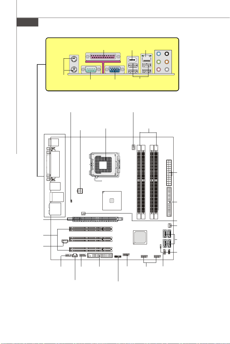
MS-7527 Mainboard
Mouse/
Keyboard,
p.En-16
JCI1,
p.En-11
Serial Port,
p.En-16
PWR1,
p.En-14
Parallel Port,
p.En-16
VGA Port,
p.En-16
CPU,
p.En-5
1394,
p.En-16
USB ports,
p.En-17
CPUFAN1,
p.En-9
LAN,
p.En-17
DDR2,
p.En-7
RS-Out
L-In
L-Out
CS-Out
Mic
SS-Out
Audio Port,
p.En-17
ATX1,
p.En-14
IDE1,
p.En-9
PCIE,
p.En-15
PCI,
p.En-15
JCD1,
p.En-12
En-4
JAUD1,
p.En-12
JCOM1,
p.En-11
JSP1,
p.En-12
FDD1,
p.En-9
J1394_1,
p.En-10
JTPM1,
p.En-12
JUSB1~2,
p.En-11
JBAT1,
p.En-13
Quick Components Guide of G31M4 Series
(MS-7527 v1.X) Mainboard
SYSFAN2,
p.En-9
SYSFAN1,
p.En-9
SATA1~4,
p.En-10
JFP1, JFP2,
p.En-10
Page 13
Central Processing Unit: CPU
The mainboard supports Intel® processor. The mainboard uses a CPU socket called
Socket 775 for easy CPU installation. If you do not have the CPU cooler, consult your
dealer before turning on the computer.
For the latest information about CPU, please visit http://global.msi.com.tw/index.php?
func=cpuform
Important
Overheating
Overheating will seriously damage the CPU and system. Always make sure the
cooling fan can work properly to protect the CPU from overheating. Make sure
that you apply an even layer of thermal paste (or thermal tape) between the CPU
and the heatsink to enhance heat dissipation.
Replaceing the CPU
While replacing the CPU, always turn off the ATX power supply or unplug the
power supply’s power cord from the grounded outlet first to ensure the safety of
CPU.
Overclocking
This mainboard is designed to support overclocking. However, please make
sure your components are able to tolerate such abnormal setting, while doing
overclocking. Any attempt to operate beyond product specifications is not
recommended. We do not guarantee the damages or risks caused by inad-
equate operation or beyond product specifications.
Engli sh
En-5
Page 14
MS-7527 Mainboard
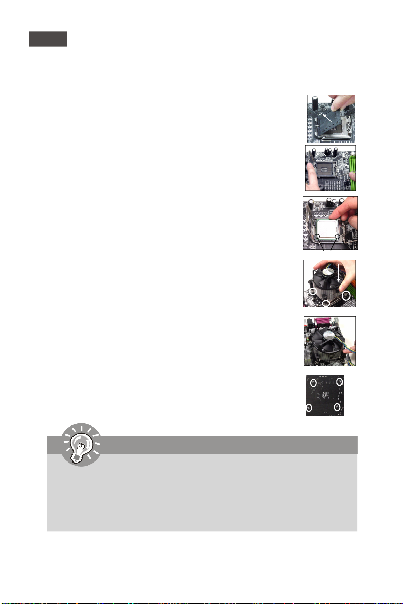
CPU & Cooler Installation Procedures for Socket 775
1. The CPU socket has a plastic cap on it to protect the contact from
damage. Before you have installed the CPU, always cover it to protect the socket pin.
2. Remove the cap from lever hinge side.
3. The pins of socket reveal.
4. Open the load lever.
5. Lift the load lever up and open the load plate.
6. After confirming the CPU direction for correct mating, put down the
CPU in the socket housing frame. Be sure to grasp on the edge of the
CPU base. Note that the alignment keys are matched.
7. Visually inspect if the CPU is seated well into the socket. If not, take
out the CPU with pure vertical motion and reinstall.
8. Cover the load plate onto the package.
9. Press down the load lever lightly onto the load plate, and then
secure the lever with the hook under retention tab.
10.Align the holes on the mainboard with the cooler. Push down the
cooler until its four clips get wedged into the holes of the mainboard.
11.Press the four hooks down to fasten the cooler. Then rotate the
locking switch (refer to the correct direction marked on it) to lock the
hooks.
12.Turn over the mainboard to confirm that the clip-ends are correctly
inserted.
alignment key
Important
1. Read the CPU status in BIOS.
2. Whenever CPU is not installed, always protect your CPU socket pin with the
plastic cap covered to avoid damaging.
3. Mainboard photos shown in this section are for demonstration of the CPU/
cooler installation only. The appearance of your mainboard may vary depending on the model you purchase.
En-6
Page 15
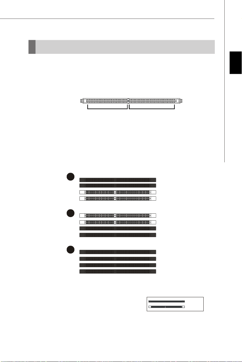
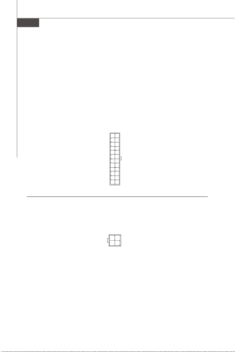
Memory
1
2
3
Installed
These DIMM slots are used for installing memory modules.
For more information on compatible components, please visit http://global.msi.com.tw/
index.php?func=testreport
DDR2
240-pin, 1.8V
64x2=128 pin56x2=112 pin
Dual-Channel Memory Population Rules
In Dual-Channel mode, the memory modules can transmit and receive data with two
data bus lines simultaneously. Enabling Dual-Channel mode can enhance the
system performance. Please refer to the following illustrations for population rules
under Dual-Channel mode.
DIMM1
DIMM2
DIMM3
DIMM4
DIMM1
DIMM2
DIMM3
DIMM4
Engli sh
DIMM1
DIMM2
DIMM3
DIMM4
Empty
En-7
Page 16
MS-7527 Mainboard
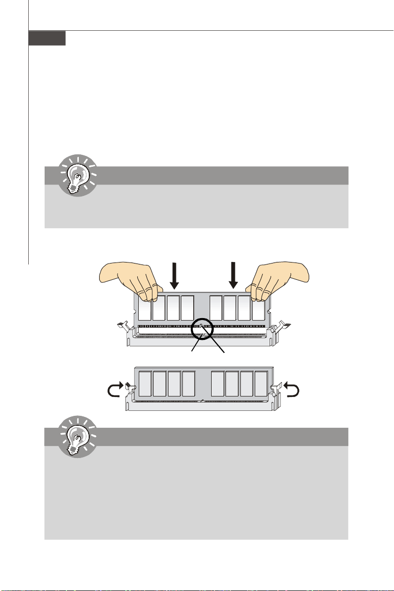
Installing Memory Modules
1. The memory module has only one notch on the center and will only fit in the right
orientation.
2. Insert the memory module vertically into the DIMM slot. Then push it in until the
golden finger on the memory module is deeply inserted in the DIMM slot. The plastic
clip at each side of the DIMM slot will automatically close when the memory module
is properly seated.
Important
You can barely see the golden finger if the memory module is properly inserted in
the DIMM slot.
3. Manually check if the memory module has been locked in place by the DIMM slot
clips at the sides.
Volt
Notch
Important
-DDR2 memory modules are not interchangeable with DDR and the DDR2
standard is not backwards compatible. You should always install DDR2
memory modules in the DDR2 DIMM slots.
-In Dual-Channel mode, make sure that you install memory modules of the
same type and density in different channel DIMM slots.
-To enable successful system boot-up, always insert the memory modules
into the DIMM1 first.
En-8
Page 17
Connectors, Jumpers, Slots
Fan Power Connectors: CPUFAN1, SYSFAN1/2
The fan power connectors support system cooling fan with +12V. The CPU FAN supports
Smart FAN function. When connect the wire to the connectors, always take note that the
red wire is the positive and should be connected to the +12V, the black wire is Ground
and should be connected to GND. If the mainboard has a System Hardware Monitor
chipset on-board, you must use a specially designed fan with speed sensor to take
advantage of the fan control.
Engli sh
Control
SENSOR
+12V
GND
CPUFAN1
SENSOR or NC
+12V
GND
SYSFAN1/2
Important
1.Please refer to the recommended CPU fans at processor’s official website or
consult the vendors for proper CPU cooling fan.
2.CPUFAN supports fan control. You can install Dual Core Center utility that
will automatically control the CPU fan speed according to the actual CPU
temperature.
3. Fan cooler set with 3 or 4 pins power connector are both available for CPUFAN.
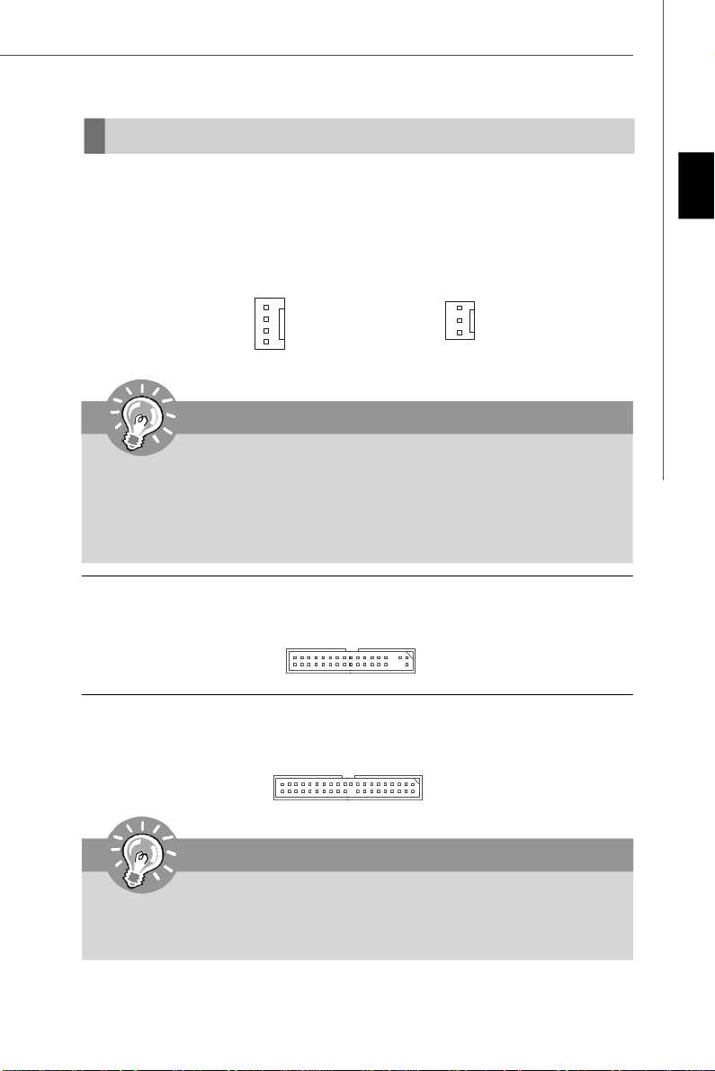
Floppy Disk Drive Connector: FDD1
This connector supports 360KB, 720KB, 1.2MB, 1.44MB or 2.88MB floppy disk drive.
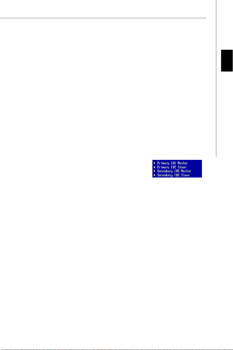
IDE connector: IDE1
This connector supports IDE hard disk drives, optical disk drives and other IDE devices.
Important
If you install two IDE devices on the same cable, you must configure the drives
separately to Master/ Slave mode by setting jumpers. Refer to IDE device’s docu-
mentation supplied by the vendors for jumper setting instructions.
En-9
Page 18
MS-7527 Mainboard
Serial ATA Connector: SATA1~4
This connector is a high-speed Serial ATA interface port. Each connector can connect to
one Serial ATA device.
SATA4
SATA2
SATA1
SATA3
Important
Please do not fold the Serial ATA cable into 90-degree angle. Otherwise, data
loss may occur during transmission.
Front Panel Connectors: JFP1, JFP2
These connectors are for electrical connection to the front panel switches and LEDs.
The JFP1 is compliant with Intel® Front Panel I/O Connectivity Design Guide.
9
Power
Switch++
Power
LED
10
-
+
Reset
-
2
JFP1
Switch
-
HDD
LED
1
Speaker
8
7
+
-
Power
+
2
JFP2
LED
1
-
IEEE1394 Connector (Green): J1394_1 (optional)
This connector allows you to connect the IEEE1394 device via an optional IEEE1394
bracket.
IEEE1394 Bracket
(Optional)
Ground
TPB-
TPA-
Cable power
2
1
Ground
10
9
TPA+
TPB+
Ground
Key (no pin)
Cable power
En-10
Page 19
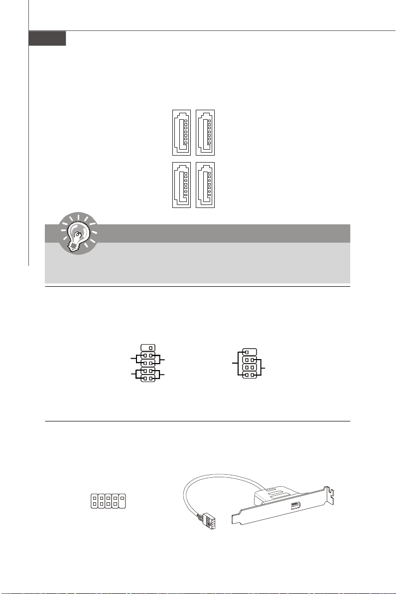
Front USB Connector (Yellow): JUSB1~2
This connector, compliant with Intel® I/O Connectivity Design Guide, is ideal for connecting high-speed USB interface peripherals such as USB HDD, digital cameras, MP3
players, printers, modems and the like.
USB 2.0 Bracket
(Optional)
2
1
VCC
VCC
USBOC
USB1-
USB1+
GND
10
9
GND
USB0-
USB0+
Key (no pin)
Important
Note that the pins of VCC and GND must be connected correctly to avoid possible
damage.
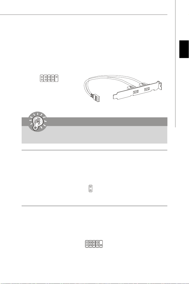
Chassis Intrusion Connector: JCI1
This connector connects to the chassis intrusion switch cable. If the chassis is opened,
the chassis intrusion mechanism will be activated. The system will record this status and
show a warning message on the screen. To clear the warning, you must enter the BIOS
utility and clear the record.
English
GND2
1
CINTRU
Serial Port Connector: JCOM1
This connector is a 16550A high speed communication port that sends/receives 16
bytes FIFOs. You can attach a serial device.
SIN
CTS
DSR
2
1
DCD
10
9
RI
RTS
SOUT DTR
Ground
En-11
Page 20
MS-7527 Mainboard
CD-In Connector: JCD1
This connector is provided for external audio input.
GND R
L
TPM module Connector: JTPM1(optional)
This connector connects to a TPM (Trusted Platform Module) module (optional). Please
refer to the TPM security platform manual for more details and usages.
3V dua l / 3V _ST B
VC C3
SIR Q
VC C5
Ke y(n o pin )
GN D
GN D
2
1
14
13
LCLK
LAD0
LAD1
LAD2
LAD3
LR ST#
LF RA ME #
S/PDIF-Out Connector: JSP1
This connector is used to connect S/PDIF (Sony & Philips Digital Interconnect Format)
interface for digital audio transmission.
VCC
GND
SPDIF
SPDIF Bracket (Optional)
Front Panel Audio Connector (Azalia Spec): JAUD1
This connector allows you to connect the front panel audio and is compliant with Intel
Front Panel I/O Connectivity Design Guide.
M IC_ J D
NC (N o pi n)
Gr oun d
Pr esen ce#
2
1
MI C _ L
LI NE ou t_ JD
10
9
M IC _R
Fr on t_J D
LIN E ou t_L
LI NE ou t_ R
En-12
®
Page 21
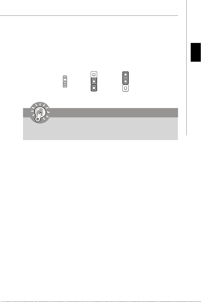
Clear CMOS Jumper: JBAT1
There is a CMOS RAM onboard that has a power supply from an external battery to keep
the data of system configuration. With the CMOS RAM, the system can automatically
boot OS every time it is turned on. If you want to clear the system configuration, set the
jumper to clear data.
English
3
1
1
Keep Data
3
1
Clear Data
Important
You can clear CMOS by shorting 2-3 pin while the system is off. Then return to 12 pin position. Avoid clearing the CMOS while the system is on; it will damage
the mainboard.
En-13
Page 22
MS-7527 Mainboard
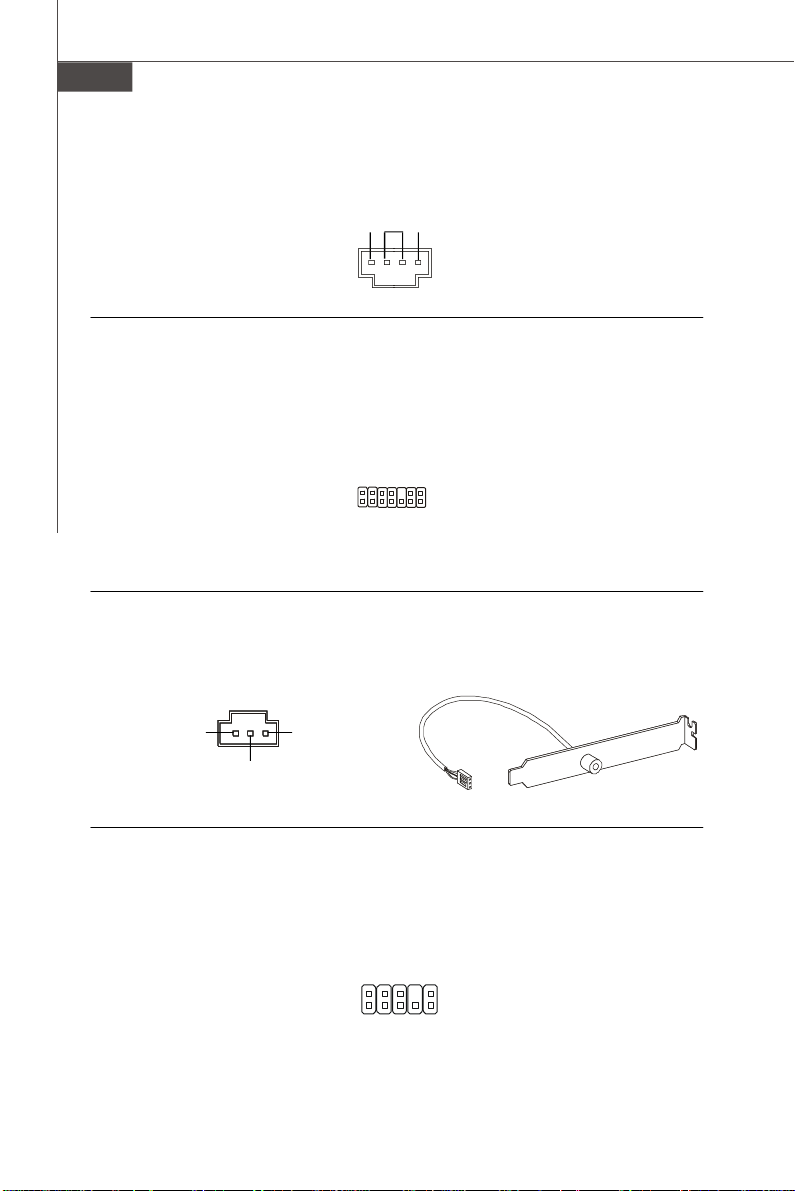
Power Supply Attachment: ATX1
Before inserting the power supply connector, always make sure that all components are
installed properly to ensure that no damage will be caused. All power connectors on
the mainbnoard have to connect to the ATX power supply and have to work together to
ensure stable operation of the mainboard.
ATX 24-Pin Power Connector: ATX1
This connector allows you to connect an ATX 24-pin power supply. To connect the ATX
24-pin power supply, make sure the plug of the power supply is inserted in the proper
orientation and the pins are aligned. Then push down the power supply firmly into the
connector.
You may use the 20-pin ATX power supply as you like. If you’d like to use the 20-pin ATX
power supply, please plug your power supply along with pin 1 & pin 13.
1224
+3.3V
+12V
+12V
5VSB
PWR OK
GND
+5V
GND
+5V
GND
+3.3V
+3.3V
GND
+5V
+5V
+5V
NC
GND
GND
GND
PS-ON#
GND
-12V
+3.3V
1
13
ATX 12V Power Connector (2x2-Pin): PWR1
This 12V power connector is used to provide power to the CPU.
4 2
GND12V
12V
GND
1
3
En-14
Page 23
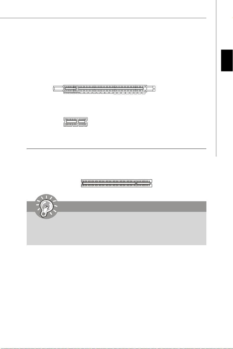
PCI Express Slot (x16/ x1)
The PCI Express slot supports the PCI Express interface expansion card.
PCI Express x16 Slot
PCI Express x 1 Slot
PCI (Peripheral Component Interconnect) Slot
The PCI slot supports LAN card, SCSI card, USB card, and other add-on cards that
comply with PCI specifications.
Important
English
When adding or removing expansion cards, make sure that you unplug the power
supply first. Meanwhile, read the documentation for the expansion card to configure
any necessary hardware or software settings for the expansion card, such as
jumpers, switches or BIOS configuration.
En-15
Page 24
MS-7527 Mainboard
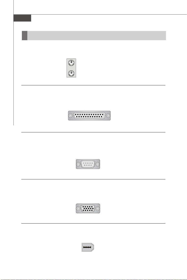
Back Panel
Mouse/Keyboard
The standard PS/2® mouse/keyboard DIN connector is for a PS/2® mouse/keyboard.
PS/2 Mouse connector (Green/ 6-pin female)
PS/2 Keyboard connector (Purple/ 6-pin female)
Parallel Port
A parallel port is a standard printer port that supports Enhanced Parallel Port (EPP) and
Extended Capabilities Parallel Port (ECP) mode.
13 1
(25-pin female connector)
1425
Serial Port
The serial port is a 16550A high speed communications port that sends/ receives 16
bytes FIFOs. You can attach a serial mouse or other serial devices directly to the
connector.
1 5
(9-Pin Male Connector)
6 9
VGA Port
The DB15-pin female connector is provided for monitor.
15
(15-Pin Female DIN Connector)
1115
1394 Port
The IEEE1394 port on the back panel provides connection to IEEE1394 devices.
En-16
Page 25
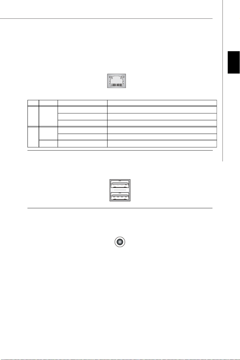
LAN
The standard RJ-45 LAN jack is for connection to the Local Area Network (LAN). You can
connect a network cable to it.
LED Color LED State Condition
Off LAN link is not established.
Left Orange On (steady state) LAN link is established.
On (brighter & pulsing) The computer is communicating with another computer on the LAN.
Green Off 10 Mbit/sec data rate is selected.
Right On 100 Mbit/sec data rate is selected.
Orange On 1000 Mbit/sec data rate is selected.
USB Port
The USB (Universal Serial Bus) port is for attaching USB devices such as keyboard,
mouse, or other USB-compatible devices.
Audio Port Connectors
These audio connectors are used for audio devices. You can differentiate the color of
the audio jacks for different audio sound effects.
English
Line-In (Blue) - Line In, is used for external CD player, tape player or other audio
devices.
Line-Out (Green) - Line Out, is a connector for speakers or headphones.
MIC (Pink) - Mic In, is a connector for microphones.
RS-Out (Black) - Rear-Surround Out in 4/ 5.1/ 7.1 channel mode.
CS-Out (Orange) - Center/ Subwoofer Out in 5.1/ 7.1 channel mode.
SS-Out (Gray) - Side-Surround Out 7.1 channel mode.
En-17
Page 26
MS-7527 Mainboard
BIOS Setup
This chapter provides basic information on the BIOS Setup program and allows you to
configure the system for optimum use. You may need to run the Setup program when:
* An error message appears on the screen during the system booting up, and requests
you to run BIOS SETUP.
* You want to change the default settings for customized features.
Important
1.The items under each BIOS category described in this chapter are under continuous update for better system performance. Therefore, the description may
be slightly different from the latest BIOS and should be held for reference only.
2.Upon boot-up, the 1st line appearing after the memory count is the BIOS
version. It is usually in the format:
A7527IMS V1.0 010108 where:
1st digit refers to BIOS maker as A = AMI, W = AWARD, and P = PHOENIX.
2nd - 5th digit refers to the model number.
6th refers to the Chipset vender as A = ATi, I = Intel, V = VIA, N = Nvidia, U = ULi.
7th - 8th digit refers to the customer as MS = all standard customers.
V1.0 refers to the BIOS version.
010108 refers to the date this BIOS was released.
En-18
Page 27
Entering Setup
Power on the computer and the system will start POST (Power On Self Test) process.
When the message below appears on the screen, press <DEL> key to enter Setup.
Press DEL to enter SETUP
If the message disappears before you respond and you still wish to enter Setup, restart
the system by turning it OFF and On or pressing the RESET button. You may also restart
the system by simultaneously pressing <Ctrl>, <Alt>, and <Delete> keys.
Getting Help
After entering the Setup menu, the first menu you will see is the Main Menu.
Main Menu
The main menu lists the setup functions you can make changes to. You can use the
arrow keys (↑↓ ) to select the item. The on-line description of the highlighted setup
function is displayed at the bottom of the screen.
Sub-Menu
If you find a right pointer symbol (as shown in the right view)
appears to the left of certain fields that means a sub-menu
containing additional options can be launched from this
field. You can use control keys (↑↓ ) to highlight the field
and press <Enter> to call up the sub-menu. Then you can
use the control keys to enter values and move from field to field within a sub-menu. If
you want to return to the main menu, just press <Esc >.
General Help <F1>
The BIOS setup program provides a General Help screen. You can call up this screen
from any menu by simply pressing <F1>. The Help screen lists the appropriate keys to
use and the possible selections for the highlighted item. Press <Esc> to exit the Help
screen.
English
En-19
Page 28
MS-7527 Mainboard
The Main Menu
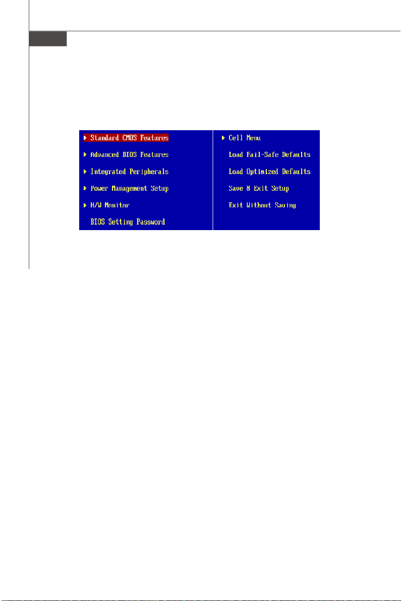
Once you enter AMI® or AWARD® BIOS CMOS Setup Utility, the Main Menu will appear
on the screen. The Main Menu allows you to select from ten setup functions and two exit
choices. Use arrow keys to select among the items and press <Enter> to accept or enter
the sub-menu.
Standard CMOS Features
Use this menu for basic system configurations, such as time, date etc.
Advanced BIOS Features
Use this menu to setup the items of special enhanced features.
Integrated Peripherals
Use this menu to specify your settings for integrated peripherals.
Power Management Features
Use this menu to specify your settings for power management.
H/W Monitor
This entry shows your PC health status.
BIOS Setting Password
Use this menu to set the password for BIOS.
Cell Menu
Use this menu to specify your settings for fequency/voltage control and overclocking.
Load Fail-Safe Defaults
Use this menu to load the default values set by the BIOS vendor for stable system
performance.
Load Optimized Defaults
Use this menu to load the default values set by the mainboard manufacturer specifically
for optimal performance of themainboard.
BIOS Setting Password
Use this menu to set the Password.
Save & Exit Setup
Save changes to CMOS and exit setup.
Exit Without Saving
Abandon all changes and exit setup.
En-20
Page 29
When enter the BIOS Setup utility, follow the processes below for general use.
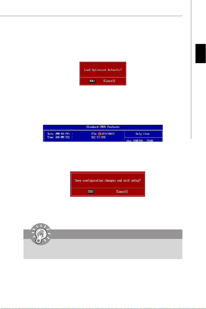
1. Load Optimized Defaults : Use control keys (↑↓ ) to highlight the Load Optimized
Defaults field and press <Enter> , a message as below appears:
Press [Ok] to load the default settings for optimal system performance.
2. Setup Date/ Time : Select the Standard CMOS Features and press <Enter> to enter
the Standard CMOS Features-menu. Adjust the Date, Time fields.
3. Save & Exit Setup : Use control keys (↑↓ ) to highlight the Save & Exit Setup field
and press <Enter> , a message as below appears:
English
Press [Ok] to save the configurations and exit BIOS Setup utility.
Important
The configuration above are for general use only. If you need the detailed
settings of BIOS, please see the manual in English version on MSI website.
En-21
Page 30
MS-7527 Mainboard
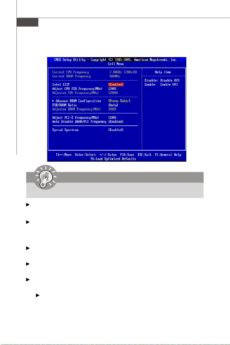
4. Cell Menu Introduction : This menu is for advanced user who want to overclock the
mainboard.
Important
Change these settings only if you are familiar with the chipset.
Current CPU / DRAM Frequency
These items show the current clocks of CPU and Memory speed. Read-only.
Intel EIST
The Enhanced Intel SpeedStep technology allows you to set the performance level
of the microprocessor whether the computer is running on battery or AC power. This
field will appear after you installed the CPU which support speedstep technology.
Adjust CPU FSB Frequency (MHz)
This item allows you to set the CPU FSB frequency (in MHz).
Adjusted CPU Frequency (MHz)
It shows the adjusted CPU frequency (FSB x Ratio). Read-only.
Advance DRAM Configuration
Press <Enter> to enter the sub-menu.
DRAM Timing Mode
Setting to [Enabled] enables DRAM CAS# Latency automatically to be
determined by BIOS based on the configurations on the SPD (Serial Presence
Detect) EEPROM on the DRAM module.
En-22
Page 31

CAS Latency(CL)
When the DRAM Timing Mode sets to [Manual], the field is adjustable.This
controls the CAS latency, which determines the timing delay (in clock cycles)
before SDRAM starts a read command after receiving it.
tRCD
When the DRAM Timing Mode sets to [Manual], the field is adjustable. When
DRAM is refreshed, both rows and columns are addressed separately. This setup
item allows you to determine the timing of the transition from RAS (row address
strobe) to CAS (column address strobe). The less the clock cycles, the faster the
DRAM performance.
tRP
When the DRAM Timing Mode sets to [Manual], the field is adjustable. This
item controls the number of cycles for Row Address Strobe (RAS) to be allowed
to precharge. If insufficient time is allowed for the RAS to accumulate its charge
before DRAM refresh, refreshing may be incomplete and DRAM may fail to
retain data. This item applies only when synchronous DRAM is installed in the
system.
tRAS
When the DRAM Timing Mode sets to [Manual], the field is adjustable. This
setting determines the time RAS takes to read from and write to a memory cell.
tRTP
When the DRAM Timing Mode sets to [Manual], time interval between a read
and a precharge command.
tRC
When the DRAM Timing Mode sets to [Manual], the field is adjustable. The row
cycle time determines the minimum number of clock cycles a memory row takes
to complete a full cycle, from row activation up to the precharging of the active
row.
English
tWR
When the DRAM Timing Mode is set to [Manual], the field is adjustable. It
specifies the amount of delay (in clock cycles) that must elapse after the
completion of a valid write operation, before an active bank can be precharged.
This delay is required to guarantee that data in the write buffers can be written
to the memory cells before precharge occurs.
tRRD
When the DRAM Timing Mode sets to [Manual], the field is adjustable. Specifies
the active-to-active delay of different banks.
tWTR
When the DRAM Timing Mode is set to [Manual], the field is adjustable. This
item controls the Write Data In to Read Command Delay memory timing. This
constitutes the minimum number of clock cycles that must occur between the
last valid write operation and the next read command to the same internal bank
of the DDR device.
En-23
Page 32

MS-7527 Mainboard
FSB/Memory Ratio
This item will allow you to adjust the FSB/Ratio of the memory.
Adjusted DRAM Frequency (MHz)
It shows the adjusted DDR Memory frequency. Read-only.
Adjust PCI-E Frequency (MHz)
This field allows you to select the PCIE frequency (in MHz).
Auto Disable DIMM/PCI Frequency
When set to [Enabled], the system will remove (turn off) clocks from empty DIMM and
PCI slots to minimize the electromagnetic interference (EMI).
Spread Spectrum
When the motherboard’s clock generator pulses, the extreme values (spikes) of the
pulses create EMI (Electromagnetic Interference). The Spread Spectrum function
reduces the EMI generated by modulating the pulses so that the spikes of the pulses
are reduced to flatter curves. If you do not have any EMI problem, leave the setting
at Disabled for optimal system stability and performance. But if you are plagued by
EMI, set to Enabled for EMI reduction. Remember to disable Spread Spectrum if you
are overclocking because even a slight jitter can introduce a temporary boost in clock
speed which may just cause your overclocked processor to lock up.
Important
1.If you do not have any EMI problem, leave the setting at [Disabled] for optimal
system stability and performance. But if you are plagued by EMI, select the
value of Spread Spectrum for EMI reduction.
2.The greater the Spread Spectrum value is, the greater the EMI is reduced,
and the system will become less stable. For the most suitable Spread Spectrum value, please consult your local EMI regulation.
3.Remember to disable Spread Spectrum if you are overclocking because even
a slight jitter can introduce a temporary boost in clock speed which may just
cause your overclocked processor to lock up.
En-24
Page 33

Software Information
Take out the Driver/Utility CD that is included in the mainboard package, and place it
into the CD-ROM driver. The installation will auto-run, simply click the driver or utiltiy
and follow the pop-up screen to complete the installation. The Driver/Utility CD contains the:
Driver menu - The Driver menu shows the available drivers. Install the driver by your
desire and to activate the device.
Utility menu - The Utility menu shows the software applications that the mainboard
supports.
WebSite menu- The WebSite menu shows the necessary websites.
Important
Please visit the MSI website to get the latest drivers and BIOS for better system
performance.
English
En-25
Page 34

G31M4
Benutzerhandbuch
Deutsch
Deutsch
De-1
Page 35

MS-7527 Mainboard
Spezifikationen
Prozessoren
- Intel® Core2 Duo/ Pentium D/ Pentium 4 / Celeron D Prescott
LGA775 Prozessoren für Sockel LGA775.
- Unterstützt Lüftersteuerung über eine 4-polige Stiftleiste.
(Weitere CPU Informationen finden Sie unter http://global.msi.com.
tw/index.php?func=cpuform)
FSB (Front-Side-Bus)
- 800/1066/1333 MHz
Chipsatz
- North-Bridge: Intel® G31 Chipsatz
- South-Bridge: Intel® ICH7 Chipsatz
Speicher
- DDR2 667/800 SDRAM (max. 4GB)
- 4 DDR2 DIMMs
(Weitere Informationen zu kompatiblen Speichermodulen finden
Sie unter http://global.msi.com.tw/index.php?func=testreport)
LAN (optional)
- Unterstützt Realtek® RTL8111C 10/100/1000 Mb/s
- Unterstützt Realtek® RTL8101E 10/100 Mb/s (optional)
- Erfüllt die Anforderungen gemäß dem Standard PCI 2.2
- Unterstützt ACPI Stromsparfunktionalität
De-2
Audio
- Onboard Chip über Realtek® ALC888
- 8-Kanal Audio-Ausgang mit “Jack Sensing”
- Zertifiziert für das Microsoft Vista Premium Betriebs-system
IEEE 1394 (optional)
- Onboard Chip über JMicron 381
- Übertragungsgeschwindigkeit von bis zu 400Mbps
IDE
- 1 IDE Port über ICH7
- Unterstützt die Betriebmodi mit Ultra DMA 66/ 100
- Unterstützt die Betriebmodi mit PIO, Bus Mastering
SATA
- 4 SATA II Ports über ICH7
- Unterstützt Datenü bertragungsraten von bis zu 3Gb/s
Page 36

Diskette
- 1 Disketten Anschluss
- Unterstützt 1 FDD mit 360KB, 720KB, 1.2MB, 1.44MB und 2.
88MB
Anschüsse
Hintere Ein-/ und Ausgänge
- 1 PS/2 Mausanschluss
- 1 PS/2 Tastaturanschluss
- 1 Serielle Anschluss (COM1)
- 1 VGA Anschluss
- 1 Parallele Schnittstelle
unterstützt die Betriebsmodi SPP/EPP/ECP
- 4 USB 2.0 Anschlüsse
- 1 RJ-45 LAN Anschluss
- 1 1394 Anschluss (optional)
- 6 Audiobuchsen
On-Board Stiftleiste/ Anschlüsse
- 2 USB 2.0 Stiftleisten
- 1 CD-Stiftleiste für Audio Eingang
- 1 SPDIF-Ausgang Stiftleiste
- 1 IEEE 1394 Stiftleiste (optional)
- 1 Audio Stiftleiste für Gehäuse Audio Ein-/ Ausgänge
- 1 Serielle Schnittstelle
- 1 TPM Schnittstelle (optional)
- 1 Gehäusekontaktschalter
Schnittstellen
- 1 PCI Express x16 Schnittstelle
- 3 PCI Schnittstellen
- Unterstützt 3.3V/ 5V PCI Bus Interface
Deutsch
Form Faktor
- Micro-ATX (24cm X 24cm)
Montage
- 6 Montagebohrungen
De-3
Page 37

MS-7527 Mainboard
Maus/
Tastatur,
s.De-16
Serielle Schnittstelle,s.De-16
Parallele Schnitt-
stelle,s.De-16
VGA Port,
s.De-16
1394,
s.De-16
USB Ports,
s.De-17
LAN,
s.De-17
RS-Out
L-In
L-Out
CS-Out
Mic
SS-Out
Audio Port,
s.De-17
PCIE,
s.De-15
PCI,
s.De-15
JCD1,
s.De-12
JAUD1,
s.De-12
JCI1,
s.De-11
PWR1,
s.De-14
JCOM1,
s.De-11
CPU,
s.De-5
FDD1,
s.De-9
CPUFAN1,
s.De-9
J1394_1,
s.De-10
DDR2,
s.De-7
JUSB1~2,
s.De-11
ATX1,
s.De-14
IDE1,
s.De-9
SYSFAN2,
s.De-9
SYSFAN1,
s.De-9
SATA1~4,
s.De-10
JFP1, JFP2,
s.De-10
JBAT1,
s.De-13
De-4
JSP1,
s.De-12
JTPM1,
s.De-12
Übersicht Eingenschaften der G31M4
Mainboard Series (MS-7527 v1.X)
Page 38

Hauptprozessor: CPU
Das Mainboard unterstützt Intel® Prozessoren und verwendet hierfür einen CPU Sockel
mit der Bezeichnung Sockel-775, um das Einsetzen der CPU zu erleichtern. Verfügen
Sie über keinen Kühler, setzen Sie sich bitte mit Ihrem Händler in Verbindung, um
einen solchen zu erwerben und danach zu installieren, bevor Sie Ihren Computer
anschalten.
Um die neuesten Informationen zu unterstützten Prozessoren zu erhalten, besuchen
Sie bitte http://global.msi.com.tw/index.php?func=cpuform
Wichtig
Überhitzung
Überhitzung beschädigt die CPU und das System nachhaltig, stellen Sie stets
eine korrekte Funktionsweise des CPU Kühlers sicher, um die CPU vor
Überhitzung zu schützen. Überprüfen Sie eine gleichmäßige Schicht der
thermischen Paste (oder thermischen Klebeandes) zwischen der CPU und dem
Kühlblech anwenden, um Wärmeableitung zu erhöhen.
CPU Wechsel
Stellen Sie vor einem Wechsel des Prozessors stets sicher, dass das ATX
Netzteil ausgeschaltet und der Netzstecker gezogen ist, um die Unversehrtheit
der CPU zu gewährleisten.
Übertakten
Dieses Motherboard wurde so entworfen, dass es Übertakten unterstützt. Stellen
Sie jedoch bitte sicher, dass die betroffenen Komponenten mit den abweichenden
Einstellungen während des Übertaktens zurecht kommen. Von jedem Versuch des
Betriebes außerhalb der Produktspezifikationen kann nur abgeraten werden. Wir
übernehmen keinerlei Garantie für die Schäden und Risiken, die aus
unzulässigem oder Betrieb jenseits der Produktspezifikationen resultieren.
Deutsch
De-5
Page 39

MS-7527 Mainboard
CPU & Kühler Einbau für Sockel 775
1. Der CPU-Sockel besitzt zum Schutz eine Plastikabdeckung. Lassen
Sie vor der Installtion diese Schutzkappe auf dem Sockel um Schäden
zu vermeiden.
2. Entfernen Sie zuerst die Schutzkappe wie abgebildet in Pfeilrichtung.
3. Sie sehen jetzt die Pins des Sockels.
4. Öffnen Sie den Sockelverschlusshebel.
5. Klappen Sie den Hebel ganz auf und öffnen Sie die
Metallverschlussklappe.
6. Vergewissem Sie sich anhand der Justiermarkierungen und dem
gelben Dreieck, daß die CPU in der korrekten Position ist. Setzen
Sie anschließend die CPU in den Sockel.
7. Begutachten Sie, ob die CPU richtig im Sockel sitzt. Falls nicht,
zeihen Sie die CPU durch eine rein vertikale Bewegung wieder
heraus. Versuchen Sie es erneut.
8. Schließen Sie die Abdeckung des Sockels.
9. Drücken Sie den Verschlusshebel mit leichtem Druck nach unten
und arretieren Sie den Hebel unter dem Rückhaltenhaken des CPU-
Sockels.
10.Frühren Sie den CPU-Kühler über den CPU-Sockel und positionieren
Sie die Arretierungsstifte des Kühlers über die daf ür vorgesehenen
Löcher des Mainboards. Drücken Sie den Kühler nach unten bis die
Stifte in den Löchern eingerastet.
11.Drücken Sie die vier Stifte nach unten um den Kühler zu arretieren.
Drehen Sie dann jeweils den Verschluss der Stifte (Richtung ist auf
dem Kühler markiert) .
12.Drehen Sie das Mainboard um und vergewissern Sie sich, dass das der
Kühler korrekt installiert ist.
alignment key
Wichtig
1. Prüfen Sie die Status der CPU im BIOS.
2. Wenn keine CPU installiert ist, schützen Sie immer den CPU-Sockel durch die
Plastikabdeckung.
3. Die Mainboard Fotos, die in diesem Abschnitt gezeigt werden, sind für Demon-
stration der CPU/ Kühler Installation. Das Aussehen Ihres mainboard kann
abhangig von dem Modell schwanken, das Sie kaufen.
De-6
Page 40

Arbeitsspeicher
Installed
1
2
3
Diese DIMM-Steckplätze nehmen Arbeitsspeichermodule auf.
Die neusten Informationen über kompatible Bauteile finden Sie unter http://global.msi.
com.tw/index.php?func=testreport.
DDR2
240-polig, 1,8V
Populationsregeln für Dual-Channel-Speicher
Im Dual-Channel-Modus können Arbeitsspeichermodule Daten über zwei
Datenbusleitungen gleichzeitig senden und empfangen. Durch Aktivierung des DualChannel-Modus wird die Leistung Ihres Systems verbessert. Bitte beachten Sie die
folgenden Abbildungen zur Veranschaulichung der Populationsregeln im DualChannel-Modus.
64x2=128 Pole56x2=112 Pole
DIMM1
DIMM2
DIMM3
DIMM4
DIMM1
DIMM2
DIMM3
DIMM4
Deutsch
DIMM1
DIMM2
DIMM3
DIMM4
Empty
De-7
Page 41

MS-7527 Mainboard
Vorgehensweise beim Einbau von Speicher Modulen
Können Sie die Kerbe auf dem Speichermodul und das Volt auf dem DIMM-Sockel
finden. Folgen Sie die unten Verfahren, um das Speichermodul richtig anzubringen.
1.Die Speichermodulen haben nur eine Kerbe in der Mitte des Moduls. Sie passen nur
in einer Richtung in den Sockel.
2.Setzen Sie den DIMM- Speicherbaustein senkrecht in den DIMM- Sockel, dann
drucken Sie ihn hinein, bis die goldenen Kontakte tief im Sockel sitzen. Die
Plastikklammern an den Seiten des DIMM- Sockels schliesen sich automatisch.
Wichtig
Sie können den goldenen Finger kaum sehen, wenn das Speichermodule richtig
im DIMM Steckplatz eingesetzt wird.
3. Überprüfen Sie manuell, wenn die Speichermodule durch den DIMM- Sockel
eingerastet worden
Volt
Notch
Wicihtig
- DDR2 und DDR können nicht untereinander getauscht werden und der Standard
DDR2 ist nicht rückwärtskompatibel, installieren Sie DDR2 Speichermodule stets
in DDR2 DIMM Slots
- Stellen Sie im Zweikanalbetrieb bitte sicher, dass Sie Module des gleichen
Typs und identischer Speicherdichte in den DDR2 DIMM Slots unterschiedlicher
Kanäle verwenden.
- Um einen sicheren Systemstart zu gewährleisten, bestücken Sie immer DIMM 1
zuerst.
De-8
Page 42

Anschlüsse, Steckbrücken und Slots
Stromanschlüsse für Lüfter: CPUFAN1, SYSFAN1/2
Die Anschlüsseunterstützen aktive Systemlüfter mit + 12V. CPU FAN kann Smart FAN
Funktion unterstützen. Wenn Sie den Anschluss herstellen, sollten Sie immer darauf
achten, dass der rote Draht der positive Pol ist, und mit +12V verbunden werden sollte,
der schwarze Draht ist der Erdkontakt und sollte mit GND verbunden werden. Ist Ihr
Mainboard mit einem Chipsatz zur Überwachung der Systemhardware versehen, dann
brauchen Sie einen speziellen Lüfter mit Tacho, um die Vorteile der Steuerung des
CPU Lüfters zu nutzen.
Control
SENSOR
+12V
GND
CPUFAN1
Wichtig
1.Bitte informieren Sie sich auf der offiziellen Website vom Prozessor über
empfohlene CPU Kühler oder fragen Sie Ihren Händler nach einem geeigneten
Lüfter.
2.CPUFAN unterstützt die Lüfterkontrolle. Sie künnen das Utility Dual Core
Center installieren, welches automatisch die Geschwindigkeit des CPU Lüfters
in Abhängigkeit von der CPU Temperatur steuert.
3. CPUFAN kann die Lüfter mit drei- und vierpolige Stecker unterstützen.
Anschluss des Diskettenlaufwerks: FDD1
Diese Anschluss unterstützt ein Diskettenlaufwerke mit 360KB, 720KB, 1.2MB, 1.44MB
oder 2.88MB Kapazität.
SENSOR or NC
+12V
GND
SYSFAN1/2
Deutsch
IDE Anschluss: IDE1
An diesen Anschluss können IDE Festplatten, optische Laufwerke (CD/DVD-Brenner, ...)
und andere Geräte betrieben werden.
Wichtig
Verbinden Sie zwei Laufwerke über ein Kabel, müssen Sie das zweite Laufwerk
im Slave-Modus konfigurieren, indem Sie entsprechend den Jumper setzen.
Entnehmen Sie bitte die Anweisungen zum Setzen des Jumpers der
Dokumentation der IDE Geräte, die der Festplattenhersteller zur Verfügung
stellt.
De-9
Page 43

MS-7527 Mainboard
Serial ATA Anschluss:SATA1~4
Der Anschluss ist eine Hochgeschwindigkeits Schnittstelle der Serial ATA. Pro Anschluss
kann ein S-ATA Gerät angeschlossen werden.
SATA4
SATA2
SATA1
SATA3
Wichtig
Bitte falten Sie das Serial ATA Kabel nicht in einem Winkel von 90 Grad, da
dies zu Datenverlusten während der Datenübertragung führt.
Frontpanel Anschlüsse: JFP1, JFP2
Diese Anschlüsse sind für das Frontpanel dienen zum Anschluss der Schalter und LEDs
des Frontpaneels. JFP1 erfüllt die Anforderungen des “Intel Front Panel I/O Connectivity Design Guide“.
9
Power
Switch++
Power
LED
10
-
+
Reset
-
2
JFP1
Switch
-
HDD
LED
1
Speaker
8
7
+
-
Power
+
2
JFP2
LED
1
-
IEEE1394 Anschluss (Grün): J1394_1
Dieser Anschluss erlaubt Ihren,die Vorrichtung IEEE1394 über ein externes IEEE1394
Slotblech anzuschließen.
IEEE1394 Slotblech
(Optional)
Ground
TPB-
TPA-
Cable power
2
1
Ground
10
9
TPA+
TPB+
Ground
Key (no pin)
Cable power
De-10
Page 44

USB Vorderanschluss (Gelb): JUSB1~3
Dieser Anschluss entspricht den Richtlinien des Intel® I/O Connectivity Design Guide, ist
bestens geeignet, Hochgeschwindigkeits- USB- Peripheriegeräte anzuschließen, wie z.
B. USB Festplattenlaufwerke, Digitalkameras, MP3-Player, Drucker, Modems und
ähnliches.
USB 2.0 Bracket
(Optional)
2
1
VCC
VCC
USBOC
USB1-
USB1+
GND
10
9
GND
USB0-
USB0+
Key (no pin)
Wichtig
Bitte beachten Sie, dass Sie die mit VCC (Stromführende Leitung) und GND
(Erdleitung) bezeichneten Pins korrekt verbinden müssen, ansonsten kann es zu
Schäden kommen.
Gehäusekontaktanschluss: JCI1
Dieser Anschluss wird mit einem Kontaktschalter verbunden. Wird das Gehäuse geöffnet,
wird der Schalter geschlossen und das System zeichnet dies auf und gibt auf dem
Bildschirm eine Warnung aus. Um die Warnmeldung zu löschen, muss das BIOS
aufgerufen und die Aufzeichnung gelöscht werden.
Deutsch
GND2
1
CINTRU
Serielle Schnittstelle: JCOM1
Bei der Anschluss handelt es sich um eine 16550A Hochgeschwindigkeitskommunikationsschnittstelle, die 16 Bytes FIFOs sendet/empfängt. An den Stecker können Sie direkt
eine Serielles Gerät anschließen.
SIN
CTS
DSR
2
1
DCD
10
9
RI
RTS
SOUT DTR
Ground
De-11
Page 45

MS-7527 Mainboard
CD- Eingang: JCD1
Dieser Anschluss wird für externen Audioeingang zur Verfügung gestellt.
GND R
L
TPM Modul Anschluss: JTPM1(optional)
Dieser Anschluss wird für das optionale TPM Modul (Trusted Platform Module) verwendt.
Weitere Informationen über den Einsatz des optionalen TPM Modules entnehmen Sie
bitte dem TPM Plattform Handbuch.
3V dua l / 3V _ST B
VC C3
SIR Q
VC C5
Ke y(n o pin )
GN D
GN D
2
1
14
13
LCLK
LAD0
LAD1
LAD2
LAD3
LR ST#
LF RA ME #
S/PDIF- Ausgang: JSP1
Dieser Anschluss dienen zum Anschluss einer SPDIF (Sony & Philips Digital Interconnect Format) Schnittstelle zur digitalen Übertragung von Audiodaten..
VCC
GND
SPDIF
SPDIF Bracket (Optional)
Audioanschluss des Frontpanels (Azalia Spec): JAUD1
Dieser Anschluss ermöglicht den Anschluss von Audioein- und -ausgängen eines
Frontpaneels. Der Anschluss entspricht den Richtlinien des “ Intel® Front Panel I/O
Connectivity Design Guide”.
M IC_ J D
NC (N o pi n)
Gr oun d
Pr esen ce#
2
1
MI C _ L
LI NE ou t_ JD
10
9
M IC _R
Fr on t_J D
LIN E ou t_L
LI NE ou t_ R
De-12
Page 46

Steckbrücke zur CMOS- Löschung: JBAT1
Auf dem Mainboard gibt es einen sogenannten CMOS Speicher (RAM), der über eine
Batterie gespeist wird und die Daten der Systemkonfiguration enthält. Er ermöglicht es
dem Betriebssystem, mit jedem Einschalten automatisch hochzufahren. Wollen Sie die
Systemkonfiguration löschen, verwenden Sie hierfür JBAT1 (Clear CMOS Jumper -
Steckbrücke zur CMOS Löschung).
3
1
1
Keep Data
3
1
Clear Data
Wichtig
Sie können den CMOS löschen, indem Sie die Pins 2-3 verbinden, während das
System ausgeschaltet ist. Kehren Sie danach zur Pinposition 1-2 zurück. Löschen
Sie den CMOS nicht, solange das System angeschaltet ist, dies würde das
Mainboard beschädigen.
Deutsch
De-13
Page 47

MS-7527 Mainboard
Zusätzlicher Hinweis Stromversorgung: ATX1
Bevor Sie eine Verbindung mit den Stromanschlüssen herstellen, stellen Sie immer
sicher, dass alle Komponenten ordnungsgemäß eingebaut sind, um jegliche Schäden
auszuschließen. Alle Stromanschlüsse auf dem Mainboard müssen mit einem ATX Netzteil
verbunden werden und müssen gemeinsam den stabilen Betrieb des Mainboards sicher
stellen.
ATX 24-Pin Stromanschluss: ATX1
Hier können Sie ein ATX 24-Pin Netzteil anschließen. Wenn Sie die Verbindung
herstellen, stellen Sie sicher, dass der Stecker in der korrekten Ausrichtung eingesteckt
wird und die Pins ausgerichtet sind. Drücken Sie dann den Netzteilstecker fest in den
Steckersockel. Sie können auch ein 20-Pin ATX Netzteil verwenden, wenn Sie möchten.
Wenn Sie ein 20-Pin ATX Netzteil einsetzen möchten, stecken Sie bitte Ihr Netzteil
beginnend bei den PinS 1 und 13 ein.
1224
+3.3V
+12V
+12V
5VSB
PWR OK
GND
+5V
GND
+5V
GND
+3.3V
+3.3V
GND
+5V
+5V
+5V
NC
GND
GND
GND
PS-ON#
GND
-12V
+3.3V
1
13
ATX 12V Stromanschluss (2x2-Pin): PWR1
Dieser 12V Stromanschluss wird verwendet, um die CPU mit Strom zu versorgen.
4 2
GND12V
12V
GND
1
3
De-14
Page 48

PCI Express Slot (x16/ x1)
Der PCI Express Slot unterstutzt die PCI Express Schnittstelle Erweiterungskarten.
PCI Express x16 Slot
PCI Express x 1 Slot
PCI (Peripheral Component Interconnect) Slot
Die PCI Steckplätze unterstützt LAN Karte, SCSI Karte, USB Karte und andere
Zusatzkarten cards,die mit PCI Spezifikationen übereinstimmen.
Wichtig
Stellen Sie vor dem Einsetzen oder Entnehmen von Karten sicher, dass Sie den
Netzstecker gezogen haben. Studieren Sie bitte die Anleitung zur
Erweiterungskarte, um jede notwendige Hard - oder Softwareeinstellung für die
Erweiterungskarte vorzunehmen, sei es an Steckbrücken (“Jumpern”), Schaltern
oder im BIOS.
Deutsch
De-15
Page 49

MS-7527 Mainboard
Hinteres Anschlusspanel
Maus-/Tastatur
Die Standard PS/2® Maus/Tastatur Stecker Mini DIN ist für eine PS/2® Maus/Tastatur .
PS/2 Mausanschluss (Grün/ 6-Pin Buchse)
PS/2 Tastaturanschluss (Lila/ 6-Pin Buchse)
Parallele Schnittstelle
Die Parallele Schnittstelle ist eine Standard Druckerschnittstelle, die ebenso als Enhanced Parallel Port (EPP) und als Extended Capabilities Parallel Port (ECP) betrieben
werden kann.
13 1
(25-Pin Centronics Anschlussbuchse)
1425
Serielle Schnittstelle
Bei der Seriellen Schnittstelle handelt es sich um eine 16550A Hochgeschwindigkeitskommunikationsschnittstelle, die 16 Bytes FIFOs sendet/empfängt. An den Stecker können
Sie direkt eine Serielle Maus oder ein anderes Serielles Gerät anschließen.
1 5
(9-Pin DIN Steckeranschluss)
6 9
VGA Anschluss
Die DB 15-Pin Buchse dient zum Anschluss eines VGA Monitors.
15
(15-Pin DIN Buchse)
1115
1394 Port
Das IEEE 1394 Port auf der hintere Anschlusspanel zu den Vorrichtungen IEEE1394.
De-16
Page 50

LAN
Die Standard RJ-45 Buchse ist für Anschlus zum an ein Lokales Netzwerk (Local Area
Network - LAN). Hier kann ein Netzwerkkabel angeschlossen werden.
LED Farbe LED Status Zustand
Aus Keine Verbindung mit dem LAN.
Links Orange An (Dauerleuchten) Verbindung mit dem LAN.
An (heller & pulsierend) Der Computer kommuniziert mit einem anderen Rechner im LAN.
Grün Aus Gewählte Datenrate 10 MBit/s.
Rechts An Gew ählte Datenrate 100 MBit/s.
Orange An Gew ählte Datenrate 1000 MBit/s.
USB Port
Dieser USB (Universal Serial Bus) Anschluss zum direkten Anschluss von USB- Geräten,
wie etwa Tastatur, Maus oder weiterer USB-kompatibler Geräte.
Audioschnittstellen
Diese Audioanschlüsse werden im Zusammenspiel mit Audioein-/ ausgabegeräten
verwendet. Anhand der Farbe der Audiobuchsen kann man unterschiedliche
Verwendungen unterscheiden.
Line-Eingang (Blau) - Line Eingang, kann für externe CD oder Kasettenspieler oder
andere Audiogeräte verwendet werden.
Line-Ausgang (Grün) - Line Ausgang, für Lautsprecher und Kopfhörer.
MIK (Pink) - Mikrofon, für Mikrofoneingang.
RS-Ausgang (Schwarz) - Hinteres Surroundsignal im 4/ 5.1/ 7.1 Kanalbetrieb.
CS-Ausgang (Orange) - Center-/ Subwooferausgang im 5.1/ 7.1 Kanalbetrieb.
SS-Ausgang (Grau) - Seitlichen Surroundsignal im 7.1 Kanalbetrieb.
Deutsch
De-17
Page 51

MS-7527 Mainboard
BIOS Setup
Dieses Kapitel enthält Informationen über das BIOS Setup und ermöglicht es Ihnen, Ihr
System optimal auf Ihre Anforderungen einzustellen. Notwendigkeit zum Aufruf des
BIOS besteht, wenn:
* Während des Bootvorgangs des Systems eine Fehlermeldung erscheint und Sie zum
Aufruf des BIOS SETUP aufgefordert werden.
* Sie die Werkseinstellungen zugunsten individueller Einstellungen ändern wollen.
Wichtig
1.Die Menüpunkte jeder BIOS Kategorie, die in diesem Kapitel beschrieben wird,
werden permanent auf den neuesten Stand gebracht, um die Systemleistung
zu verbessern. Aus diesem Grunde kann die Beschreibung geringfügig von
der aktuellsten Version des BIOS abweichen und sollte dementsprechend
lediglich als Anhaltspunkt dienen.
2. Während des Hochfahrens, wird die BIOS Version in der ersten Zeile nach dem
Hochzählen des Speichers angezeigt, üblicherweise im Format dieses Beispiels:
A7527IMS V1.0 010108 wobei:
Die erste Stellen den BIOS-Hersteller bezeichnet, dabei gilt A = AMI, W = AWARD,
and P = PHOENIX.
2te - 5te Stelle bezeichnet die Modelnummer.
6te Stelle bezeichnet den Chipsatzhersteller, A = AMD, I = Intel, V = VIA, N =
Nvidia, U = ULi.
7te - 8te Stelle bezieht sich auf den Kunden, MS=alle Standardkunden.
V1.0 bezieht sich auf die BIOS Version.
010108 bezeichnet das Datum der Veröffentlichung des BIOS.
De-18
Page 52

Aufruf des BIOS Setups
Nach dem Einschalten beginnt der Computer den POST (Power On Self Test Selbstüberprüfung nach Anschalten). Sobald die Meldung unten erscheint, drücken Sie
die Taste <Entf>(<Del>) um das Setup aufzurufen.
Press DEL to enter SETUP
Wenn die Nachricht verschwindet, bevor Sie reagieren und Sie möchten immer noch
ins Setup, starten Sie das System neu, indem Sie es erst AUS- und danach wieder
ANSCHALTEN, oder die “RESET”-Taste am Gehäuse betätigen. Sie können das Sys-
tem außerdem neu starten, indem Sie gleichzeitig die Tasten <Strg>,<Alt> und <Entf>
drücken (bei manchen Tastaturen <Ctrl>,<Alt> und <Del>).
Hilfe finden
Nach dem Start des Setup Menüs erscheint zuerst das Hauptmenü.
Hauptmenü
Das Hauptmenü listet Funktionen auf, die Sie ändern können. Sie können die
Steuertasten (↑↓ ) verwenden, um einen Menüpunkt auszuwählen. Die Online-
Beschreibung des hervorgehobenen Menüpunktes erscheint am unteren Bildschirmrand.
Untermenüs
Wenn Sie an der linken Seite bestimmter Felder ein
Dreieckssymbolf finden (wie rechts dargestellt), bedeuted
dies, dass Sie über das entsprechende Feld ein Untermenü
mit zusätzlichen Optionen aufrufen können. Durch die
Steuertasten (↑↓ )önnen Sie ein Feld hervorheben und durch Drücken der Eingabetaste
<Enter> in das Untermenü gelangen. Dort können Sie mit den Steuertasten Werte
eingeben und navigieren. Durch Drücken von <Esc > kommen Sie zurück ins Hauptmenü.
Deutsch
Allgemeine Hilfe <F1>
Das BIOS Setup verfügt über eine Allgemeine Hilfe (General Help). Sie können diese
aus jedem Menü einfach durch Drücken der Taste <F1> aufrufen. Sie listet die Tasten
und Einstellungen zu dem hervorgehobenen Menüpunkt auf. Um die Hilfe zu verlassen,
drücken Sie <Esc>.
De-19
Page 53

MS-7527 Mainboard
Das Hauptmenü
Nachdem Sie das AMI® oder AWARD® BIOS CMOS Setup Utility, aufgerufen haben,
erscheint das Hauptmenü. Es weist zehn Setup- Funktionen und zwei Arten das Menü zu
verlassen auf. Verwenden Sie die Pfeiltasten, um im Menü zu navigieren und drücken
Sie die Eingabetaste (<Enter>), um ein Untermenü aufzurufen.
Standard CMOS Features
In diesem Menü können Sie die Basiskonfiguration Ihres Systems anpassen, so z.B.
Uhrzeit, Datum usw.
Advanced BIOS Features
Verwenden Sie diesen Menüpunkt, um weitergehende Einstellungen an Ihrem System
vorzunehmen.
Integrated Peripherals
Verwenden Sie dieses Menü, um die Einstellungen für in das Board integrierte
Peripheriegeräte vorzunehmen.
Power Management Setup
Verwenden Sie dieses Menü, um die Einstellungen für die Stromsparfunktionen
vorzunehmen.
H/W Monitor
Dieser Eintrag zeigt den generellen Systemstatus.
BIOS Setting Password
Verwenden Sie dieses Menü, um das Kennwort für das BIOS einzugeben.
Cell Menu
Hier können Sie ihre Einstellungen zur Kontrolle von Frequenz und Spannung und zur
Übertaktung vornehmen.
Load Fail-Safe Defaults
In diesem Menü können Sie eine stabile, werkseitig gespeicherte Einstellung des BIOS
Speichers laden. Nach Anwählen des Punktes sichern Sie die Änderungen und starten
das System neu.
Load Optimized Defaults
In diesem Menü können Sie die BIOS-Voreinstellungen laden, die der
Mainboardhersteller zur Erzielung der besten Systemleistung vorgibt.
Save & Exit Setup
Abspeichern der BIOS-Änderungen im CMOS und verlassen des BIOS.
Exit Without Saving
Verlassen des BIOS´ ohne Speicherung, vorgenommene Änderungen verfallen.
De-20
Page 54

Wenn hereinkommen Sie, gründen das BIOS Dienstprogramm, folgen Sie den Prozessen
unten für allgemeinen Gebrauch.
1. Last optimierte Rückstellungen : Die Gebrauchsteuerschlüssel ( ↑↓ ),, zum der Last
optimierten Rückstellungen hervorzuheben fangen auf und betä tigen <Eingabe>,
eine Anzeige wie erscheint unten:
Wählen Sie [Ok] und drücken Einter, um die Standard Einstellungen für ein optimales
System zu laden.
2. Einstellung Datum/ Zeit : Wählen Sie die “Standard-CMOS Eigenschaften” vor und
betätigen Sie <Eingabe> um das Standard-CMOS Eigenschaft -Menü einzutragen.
Justieren Sie das Datum, Zeit fängt auf.
3. Außer u. Ausgang Einstellung : Die Gebrauchsteuerschlussel (↑↓ ), zum der Au ßer
u. Ausgang Einstellung hervorzuheben fangen auf und betätigen <Eingabe>, eine
Anzeige wie erscheint unten:
Deutsch
Wählen Sie[Ok] und drücken Einter, um die (neuen) Einstellungen zu speichern und
das BIOS Setup zu verlassen.
Wichtig
Die Konfiguration oben dienen nur generellen Zwecken. Wenn Sie detaillierte
BIOS- Einstellungen benötigen, dann sehen Sie bitte das Handbuch in Englischer
Sprache auf der MSI Website ein.
De-21
Page 55

MS-7527 Mainboard
4. Cell Menu Introduction : Das Menü ist für den weiteren Benutzer, der die Hauptplatine
übertakten mögen.
Wichtig
Nur wenn Sie mit dem Chipsatz vertraut sind, können Sie die Einstellung
ändern .
Current CPU / DRAMfrequenz
Zeigt die derzeitige Frequenz der CPU/ Speicher. Nur Anzeige.
Intel EIST
Die erhöhte Intel SpeedStep Technologie erlaubt Ihnen, das Leistungsgrad des
Mikroprozessors einzustellen, ob der Computer auf Batterie oder Wechselstrom läuft.
Wenn Sie das CPU Ratio zu justieren möchten, lautet die Einstellung auf “Disabled
(ausgeschaltet)”. Nur Sie brachten die CPU an, das Speedstep Technologie stützen.
Adjust CPU FSB Frequency (MHz)
Hier können Sie die CPU FSB Frequenz angeben (in MHz).
Adjusted CPU Frequency (MHz)
Zeigt die verstellte Frequenz der CPU (FSB x Ratio). Nur Anzeige.
Advance DRAM Configuration
Drücken Sie die Eingabetaste <Enter>, um das folgende Untermenü aufzurufen.
DRAM Timing Mode
Die Einstellung [Enabled] ermöglicht die automatische Erkennung des DRAM
timings durch das BIOS auf Basis der Einstellungen im SPD. Das Vorwählen
De-22
Page 56

[Manual] eingestellt, können Sie den DRAM Timing anpassen
CAS Latency(CL)
Lautet die Einstellung unter DRAM Timing [Manual], können Sie hier die DRAM
Timing angeben. Hier wird die Verzögerung im Timing (in Taktzyklen)
eingestellt, bevor das SDRAM einen Lesebefehl nach dessen Erhält auszuführen
beginnt.
tRCD
Lautet die Einstellung unter DRAM Timing [Manual], können Sie hier die DRAM
Timing angeben. Wenn DRAM erneuert wird, werden Reihen und Spalten
separat adressiert. Gestattet es, die Anzahl der Zyklen der Verzogerung im
Timing einzustellen, die zwischen den CAS und RAS Abtastsignalen liegen, die
verwendet werden, wenn der DRAM beschr ieben, ausgelesen oder aufgef rischt
wird. Eine hohe Geschwindigkeit fuhrt zu hoherer Leistung, während langsamere
Geschwindigkeiten einen stabileren Betrieb bieten.
tRP
Lautet die Einstellung unter DRAM Timing [Manual], können Sie hier die DRAM
Timing angeben. Legt die Anzahl der Taktzyklen fest, die das
Reihenadressierungssignal (Row Address Strobe - RAS) für eine Vorladung
bekommt. Wird dem RAS bis zur Auffrischung des DRAM nicht genug Zeit zum
Aufbau seiner Ladung gegeben, kann der Refresh unvollstandig ausfallen und
das DRAM Daten verlieren. Dieser Menüpunkt ist nur relevant, wenn synchroner
DRAM verwendet wird.
tRAS
Wenn das DRAM TIMING auf [Manual] einstellt, stellt diese Einstellung das
Nehmen der Zeit RAS fest, um von zu lesen und zu einer Speicherzelle zu
schreiben.
tRTP
Lautet die Einstellung unter DRAM Timing [Manual], können Sie hier die DRAM
Timing angeben. Legt die Pausenzeit zwischen ein Lesen Befehl und einem
Vorladung Befehl.
Deutsch
tRC
Lautet die Einstellung unter DRAM Timing [Manual], können Sie hier die DRAM
Timing angeben. Die Reihe Taktzyklen Option spezifiziert die Mindestdauer der
Taktgeberzyklen. Die Speicherreihe einen vollen Zyklus Zeit braucht, von der
Reihe Aktivierung bis zu Precharge der aktiven Reihe fest.
tWR
Lautet die Einstellung unter DRAM Timing [Manual], können Sie hier die DRAM
Timing angeben. Unter dieser Optionlegen Sie die WR-Verzögerung (in den
Taktgeberzyklen) fest. Dieses Verzögerung muss garantieren, dass Daten in den
schreibenpuffern werden können zu den Speicherzellen geschrieben, bevor Vor-
Aufladung auftritt.
tRRD
Lautet die Einstellung unter DRAM Timing [Manual], können Sie hier die DRAM
Timing angeben. Diese Option legt die Aktiv-zu-Aktive Verzögerung von den
unterschiedlichen angegrenzter Teil des Speicher fest.
De-23
Page 57

MS-7527 Mainboard
tWTR
Lautet die Einstellung unter DRAM Timing [Manual], können Sie hier die DRAM
Timing angeben. Hier stellen Sie den tWTR-Wert (Write Data In to Read
Command Delay memory Timing) ein. Dieses setzt die Mindestzahl der
Taktgeberzyklen fest, müssen die zwischen dem letzten gültigen
Schreibenarbeitsgang und der folgende gelesene Befehl zur gleichen internen
Bank der DDR Vorrichtung auftreten
FSB/Memory Ratio
Können Sie hier den FSB/Ratio des Speichers anpassen..
Adjusted DRAM Frequency (MHz)
Gibt der verstellt Frequenz des DDR Speicher. Nur Anzeige.
Adjust PCI-E Frequency (MHz)
Gestattet die Wahl der PCI-E Frequenz (in MHz).
Auto Disable DIMM/PCI Frequency
Lautet die Einstellung auf [Enabled] (eingeschaltet), deaktiviert das System die
Taktung leerer PCI Sockel, um die Elektromagnetische Störstrahlung (EMI) zu
minimieren.
Spread Spectrum
Pulsiert der Taktgenerator des Motherboards, erzeugen die Extremwerte (Spitzen) der
Pulse EMI (Elektromagnetische Interferenzen). Die Spread Spectrum Funktion
reduziert die erzeugten EMI, indem die Pulse so moduliert werden, das die
Pulsspitzen zu flacheren Kurven reduziert werden.
Wichtig
1.Sollten Sie keine Probleme mit Interferenzen haben, belassen Sie es bei
der Einstellung [Disabled] (ausgeschaltet), um bestmögliche Systems tabilität und -leistung zu gewährleisten. Stellt für sie EMI ein
Problem dar, wählen Sie die gewünschte Bandbreite zur Reduktion der EMI.
2.Je größer Spread Spectrum Wert ist, desto größer nimmt der EMI ab, und das
System wird weniger stabil. Bitte befragen Sie Ihren lokalen EMI Regelung
zum meist passend Spread Spectrum Wert.
3.Denken Sie daran Spread Spectrum zu deaktivieren, wenn Sie übertakten,
da sogar eine leichte Schwankung eine vorübergehende Taktsteigerung
erzeugen kann, die gerade ausreichen mag, um Ihren übertakteten Prozessor
zum einfrieren zu bringen.
De-24
Page 58

Software-Informationen
Nehmen Sie den Treiber herausGebrauchs-CD, die im mainboard Paket eingeschlossen
ist, und setzen Sie es in den CD-ROM Treiber. Die Installation wird Automobil-laufen
lassen, klicken Sie einfach den Treiber oder utiltiy und folgen Sie dem pop-up Schirm,
um die Installation durchzuführen. Der TreiberGebrauchs-CD enthält:
Treibermenü - das Treibermenü zeigt die vorhandenen Treiber. Bringen Sie den Treiber
durch Ihren Wunsch und die Vorrichtung zu aktivieren an.
Gebrauchsmenmenü - das Gebrauchsmenü zeigt die SoftwareAnwendungen das die
mainboard Unterstützungen.
WebSite Menü - das Website Menü zeigt die notwendigen Website.
Wichtig
Besichtigen Sie bitte die MSI Website, um die neuesten Treiber und BIOS für
bessere System Leistung zu erhalten.
Deutsch
De-25
Page 59

G31M4
Guide d’utilisation
Français
Français
Fr-1
Page 60

Carte mère MS-7527
Spécifications
Processeurs Supportés
- Intel® Core2 Duo/ Pentium D/ Pentium 4 / Celeron D Prescott
LGA775 processeurs dans le paquet LGA775.
- Supporte le connecteur de 4 pins du ventilateur de CPU avec le
contrôle de la vitesse du ventilateur.
(Pour plus d’informations sur le CPU, veuillez visiter http://global.
msi.com.tw/index.php?func=cpuform)
FSB Supporté
- 800/1066/1333 MHz
Chipset
- North Bridge : chipset Intel® G31
- South Bridge : chipset Intel® ICH7
M émoire Supporté
- DDR2 667/800 SDRAM (4GB Max)
- 4 DDR2 DIMMs
(Pour plus d’informations sur les composants compatibles, veuillez
visiter http://global.msi.com.tw/index.php?func=testreport)
LAN (optionnel)
- Supporte Realtek® RTL8111C 10/100/1000 Mb/s
- Supporte Realtek® RTL8101E 10/100 Mb/s (optionnel)
- Compatible avec PCI 2.2
- Supporte ACPI Power Management
Fr-2
Audio
- Puce intégrée par Realtek® ALC888
- 8-canaux audio flexible avec détection de jack
- Compatible avec vista premium
IEEE 1394 (optionnel)
- Puce intégrée par JMicron 381
- Le taux de transfert jusqu’à 400Mbps
IDE
- 1 port IDE par ICH7
- Supporte le mode Ultra DMA 66/100
- Supporte les modes d’opération PIO, Bus Master
SATA
- 4 ports SATA II par ICH7
- Supporte le taux de transfert jusqu’à 3Gb/s
Page 61

Disquette
- 1 port de disquette
- Supporte 1 FDD avec 360KB, 720KB, 1.2MB, 1.44MB et 2.88MB
Connecteurs
Panneau arrière
- 1 port souris PS/2
- 1 port clavier PS/2
- 1 port sérial (COM1)
- 1 port VGA
- 1 port parallèle supportant le mode SPP/EPP/ECP
- 4 ports USB 2.0
- 1 jack RJ-45 LAN
- 1 jack 1394 (optionnel)
- 6 jacks audio flexibles
Connecteur intégrés
- 2 connecteurs USB 2.0
- 1 connecteur CD-in
- 1 connecteur SPDIF-Out
- 1 connecteur IEEE 1394 (optionnel)
- 1 connecteur audio avant
- 1 connecteur de port sérial
- 1 connecteur TPM (optionnel)
- 1 connecteur Châssis Intrusion
Slots
- 1 slot PCI Express x16
- 3 slots PCI
- Supporte l’interface bus PCI 3.3V/ 5V
Français
Dimension
- Micro-ATX (24cm X 24cm)
Montage
- 6 trous de montage
Fr-3
Page 62

Carte mère MS-7527
Souris/
Clavier,
p.Fr-16
JCI1,
p.Fr-11
Port Sérial,
p.Fr-16
PWR1,
p.Fr-14
Port Parallèle,
p.Fr-16
Port VGA,
p.Fr-16
CPU,
p.Fr-5
1394,
p.Fr-16
Ports USB,
p.Fr-17
CPUFAN1,
p.Fr-9
LAN,
p.Fr-17
DDR2,
p.Fr-7
RS-Out
L-In
L-Out
CS-Out
Mic
SS-Out
Port Audio,
p.Fr-17
ATX1,
p.Fr-14
IDE1,
p.Fr-9
PCIE,
p.Fr-15
PCI,
p.Fr-15
JCD1,
p.Fr-12
Fr-4
JAUD1,
p.Fr-12
JCOM1,
p.Fr-11
JSP1,
p.Fr-12
FDD1,
p.Fr-9
J1394_1,
p.Fr-10
JTPM1,
p.Fr-12
JUSB1~2,
p.Fr-11
JBAT1,
p.Fr-13
Guide des composants des séries G31M4
Carte mère (MS-7527 v1.X)
SYSFAN2,
p.Fr-9
SYSFAN1,
p.Fr-9
SATA1~4,
p.Fr-10
JFP1, JFP2,
p.Fr-10
Page 63

Unité centrale (CPU)
La carte mère supporte les processeurs Intel®. Le socket 775 permet une installation
facile du CPU. Assurez-vous que l’unité centrale soit équipée d’un ventilateur de
refroidissement attaché sur le dessus pour éviter la surchaffe. Si vous n’en avez pas,
contactez votre revendeur pour en acheter et installez les avant d’allumer votre ordinateur.
Pour les dernières informations sur le CPU, veuillez visiter http://global.msi.com.tw/
index.php?func=cpuform
Important
Surchauffe
La surchauffe endommage sérieusement l’unité centrale et le système. Assurez-
vous toujours que le ventilateur de refroidissement fonctionne correctement
pour protéger l’unité centrale contre la surchauffe. Assurez-vous d’appliquer
une couche d’enduit thermique (ou film thermique) entre l’unité centrale et le
dissipateur thermique pour améliorer la dissipation de la chaleur.
Remplacement de l’unité centrale
Lorsque vous remplacez l’unité centrale, commencez toujours par couper
l’alimentation électrique de l’ATX ou par débrancher le cordon d’alimentation
de la prise mise à la terre pour garantir la sécurité de l’unité centrale.
Overclocking
Cette carte mère supporte l’overclocking. Néanmoins, veuillez vous assurer que
vos composants soient capables de tolérer ces configurations anormales, lors
d’overclocking. Tout envie d’opérer au dessus des spécifications du produit
n’est pas recommandé. Nous ne garantissons pas les dommages et risques
causés par les opérations insuffisantes ou au dessus des spécifications du
produit.
Français
Fr-5
Page 64

Carte mère MS-7527
Installation du CPU et son ventilateur pour Socket 775
1. Le socket CPU possède un plastique de protection. Ne le retirer qu’au
moment d’installer le CPU.
2. Enlevez le chapeau de la charnière du levier.
3. On révèle les vroches de la douille.
4. Ouvrez le levier de charge.
5. Lever le levier et ouvrir le plateau de chargement .
6. Après avoir confirmé la direction du CPU pour joindre correctement,
déposez le CPU dans l’armature du logement de douille. Faites
attention au bord de sa base. Notez qu’on aligne les coins assortis.
7. Inspectez visuellement si le CPU est bien posé dans le douille.
Sinon, sortez verticalement le CPU pur et la réinstallez.
8. Couvrez le plat de charge sur le paquet.
9. Abaissez le levier sur le plateau de chargement, puis sécuriser
l’ensemble avec le mécanisme de rétention.
10. Aligner les trous de la carte avec le ventilateur. Installer le ventilateur
dans les trous de la carte mère.
11. Appuyer sur le crochets pour attaher le ventilateur. Puis effectuer
une rotation des systèmes de rétention ( voir ventilateur pour le sens
de rotation).
12. Retourner la carte mère pour s’assurer que le ventilateur est
correctement installé.
alignment key
Important
1. Lisez le statut du CPU dans le BIOS.
2. Quand le CPU n’est pas installé, toujours protectez votre pin du socket CPU
avec le plastique de protection pour éviter tout dommage.
3. Les photos de la carte montrées dans cette section ne sont que pour une
démonstration de l’installation du CPU et son ventilateur. L’appearance de
votre carte mère peut varier selon le modèle que vous achetez.
Fr-6
Page 65

Mémoire
1
2
3
Installed
Ces slots de DIMM (module de mémoire à double rangée de connexion) sont destinés
à installer les modules de mémoire.
Pour plus d’informations sur les composants compatibles, veuillez visiter http://global.
msi.com.tw/index.php?func=testreport
DDR2
240-pin, 1.8V
64x2=128 pin56x2=112 pin
Règles de population des mémoires à canal double
En mode de Canal double, les modules de mémoire peuvent transmettre et recevoir
les données avec simultanément deux lignes omnibus de données. L’activation du
mode de Canal double peut améliorer les performances du système. Veuillez vous
reporter aux illustrations suivantes pour connaître les règles de population en mode
de Canal double.
DIMM1
DIMM2
DIMM3
DIMM4
DIMM1
DIMM2
DIMM3
DIMM4
DIMM1
DIMM2
DIMM3
DIMM4
Empty
Français
Fr-7
Page 66

Carte mère MS-7527
Installation des modules de mémoire
1. Le module de mémoire possède une seule encoche en son centre et ne s’adaptera
que s’il est orienté de la manière convenable.
2. Insérez le module de mémoire à la verticale dans le slot du DIMM. Poussez-le
ensuite jusqu’à l’extrémité dorée du module de mémoire, soit profondément insérée
dans le slot du DIMM.
Important
Vous pourrez à peine voir l’extrémité dorée si le module de mémoire est correctement
inséré dans le slot du DIMM.
3. Vérifiez manuellement si la barrette mémoire a ét é verrouillée en place par les clips
du slot DIMM sur les côtés.
Volt
Encoche
Important
-Les modules DDR2 ne sont pas interchangeables par DDR et vice versa.
Vous devez toujours installer les modules de mémoire DDR2 dans les slots
DDR2 DIMM.
-En mode Dual-Channel, assurez-vous que vous installez les modules de
mémoire du même type et de la même densité dans les slots DIMM de
canaux différents.
- Pour lancer avec succès votre ordinateur, insérez tout d’abord les modules
de mémoire dans le DIMM1.
Fr-8
Page 67

Connecteurs, Cavaliers, Slots
Connecteurs d’alimentation du ventilateur : CPUFAN1, SYSFAN1/2
Les connecteurs de courant du ventilateur supportent le ventilateur de refroidissement du
système avec +12V. Le ventilateur du CPU supporte la fonction de Smart FAN. Lors du
branchement des fils aux connecteurs, faites toujours en sorte que le fil rouge soit le fil
positif devant être relié au connecteur +12V; et que le fil noir soit le fil de mise à la terre
devant être relié au connecteur de mise à la terre GND. Si la carte mère est équipée d’un
jeu de puces intégré pour moniteur de matériel de système, vous devrez utiliser un
ventilateur spécial pourvu d’un capteur de vitesse afin de contrôler le ventilateur de
l’unité centrale.
Control
SENSOR
+12V
GND
CPUFAN1
Important
1.Veuillez consulter les ventilateurs d’unité centrale recommandés sur les sites
officiels des fabricants de processeurs ou bien consultez votre revendeur
pour obtenir des informations sur le ventilateur de refroidissement adapté à
votre unité centrale.
2.Le CPUFAN (ventilateur de processeur) 1 accepte la commande du ventilateur.
Vous pouvez activer la fonction Smart Fan (ventilation intelligente) dans
l’utilitaire de configuration du BIOS pour contrōler automatiquement la vitesse
du ventilateur processeur en fonction de la température réelle du processeur.
3. Ventilateur avec 3 ou 4 broches sont tous deux disponibles pour CPUFAN.
Connecteur Floppy Disk Drive
Ce connecteur supporte le lecteur de disquette de 360KB, 720KB, 1.2MB, 1.44MB ou
2.88MB.
SENSOR or NC
+12V
GND
SYSFAN1/2
Français
Connecteur IDE : IDE1
Ce connecteur supporte les lecteurs de disque dur IDE, lecteurs optiques de disque et
d’autre périphériques IDE.
Important
Si vous installez deux périphériques IDE sur le même câble, vous devez configurer
les périphériques séparément en mode Master/ Slave par les cavaliers de
configuration. Référez-vous aux documentations des périphériques de IDE offertes
par votre vendeur pour les instructions de configurations des cavaliers.
Fr-9
Page 68

Carte mère MS-7527
Connecteur Serial ATA
Ce connecteur est un port d’interface de série ATA haut débit. Chaque connecteur peut
être relié à un appareil de série ATA.
SATA4
SATA2
SATA1
SATA3
Important
Veuillez ne pas plier le câble de série ATA à 90°. Autrement des pertes de
données pourraient se produire pendant la transmission.
Conncteur du panneau avant : JFP1, JFP2
Ces connecteurs sont fournis pour la connecxion électrique aux interrupteus et LEDs du
panneau avant. Il est conforme au guide de conception de la connectivité Entrée/sortie
du panneau avant Intel®.
9
Power
Switch++
Power
LED
10
-
+
Reset
-
2
JFP1
Switch
-
HDD
LED
1
Speaker
8
7
+
-
Power
+
2
JFP2
LED
1
-
Connecteur IEEE1394 (Vert) : J1394_1 (optionnel)
Ce connecteur vous permet de relier un appareil IEEE1394 via un support optionnel
IEEE1394.
Support IEEE1394
(Optionnel)
Ground
TPB-
TPA-
Cable power
2
1
Ground
10
9
TPA+
TPB+
Ground
Key (no pin)
Cable power
Fr-10
Page 69

Connecteur USB avant (Jaune) : JUSB1~2
Ce connecteur est conforme au guide de conception de la connectivité Entrée/sortie
du panneau avant Intel®, il est idéal pour relier les périphériques d’interface USB à
haut débit tels les disques durs externes, les appareils photo numériques, les
lecteurs MP3, les imprimantes, les modems et les appareils similaires.
Support USB 2.0
(Optionnel)
2
1
VCC
VCC
USBOC
USB1-
USB1+
GND
10
9
GND
USB0-
USB0+
Key (no pin)
Important
Notez que les broches de VCC (Connexion de voie virtuelle) et GND (terre)
doivent être branchées correctement afin d’éviter tout dommage possible.
Connecteur de Châssis Intrusion : JCI1
Ce connecteur est connecté à un câble châssis intrusion switch. Si le châssis est ouvert,
le switch en informera le système, qui enregistera ce statut et affichera un écran d’alerte.
Pour effacer ce message d’alerte, vous devez entrer dans le BIOS et désactiver l’alerte.
Français
GND2
1
CINTRU
Connecteur Port Serial : JCOM1
Le port serial est un port de communications de haute vitesse de 16550A, qui envoie/
reçoit 16 bytes FIFOs. Vous pouvez attacher une souris serial ou d’autres périphériques
directement à ce connecteur.
SIN
CTS
DSR
2
1
DCD
10
9
RI
RTS
SOUT DTR
Ground
Fr-11
Page 70

Carte mère MS-7527
Connecteur CD-In : JCD1
Ce connecteur est fournit pour un audio externe d’entrer.
GND R
L
Connecteur TPM Module : JTPM1(optionnel)
Ce connecteur est rélié à TPM (Trusted Platform Module) Module (optionnel). Veuillez
vous référer au manuel de TPM plat-forme de sécurité pour plus de détails et d’utilisations.
3V dua l / 3V _ST B
VC C3
SIR Q
VC C5
Ke y(n o pin )
GN D
GN D
2
1
14
13
LCLK
LAD0
LAD1
LAD2
LAD3
LR ST#
LF RA ME #
Connecteur S/PDIF-Out : JSP1
Ce connecteur est utilisé pour relier à l’interface S/PDIF (Sony & Philips Digital Interconnect Format) de la transmission audio numérique.
VCC
GND
SPDIF
Support SPDIF (Optionnel)
Connecteur audio panneau avant (Spécifications d’Azalia): JAUD1
Ce connecteur vous permet de connecter un audio sur le panneau avant. Il est conforme
au guide de conception de la connectivité Entrée/sortie du panneau avant Intel®.
M IC_ J D
NC (N o pi n)
Gr oun d
Pr esen ce#
2
1
MI C _ L
LI NE ou t_ JD
10
9
M IC _R
Fr on t_J D
LIN E ou t_L
LI NE ou t_ R
Fr-12
Page 71

Cavalier d’effacement du CMOS : JBAT1
Il y a un CMOS RAM intégré, qui possède un bloc d’alimentation alimenté par une
batterie externe, destiné à conserver les données de configuration du système. Avec le
CMOS RAM, le système peut lancer automatiquement le système d’exploitation chaque
fois qu’il est allumé. Si vous souhaitez effacer la configuration du système, réglez le
cavalier de manière à effacer les données.
3
1
conserver les données
1
3
1
Effacer les données
Important
Vous pouvez effacer le CMOS en raccourcissant 2-3 broches quand le système
est éteint. Retournez ensuite en position 1-2 broches. Evitez d’effacer le CMOS
pendant que le système est allumé; cela endommagerait la carte mère.
Français
Fr-13
Page 72

Carte mère MS-7527
Attachement d’Alimentation d’Énergie : ATX1
Avant d’insérer le connecteur d’alimentation d’énergie, assurez-vous toujours que tous
les composants sont installés correctement afin de ne pas causer de dommage. Tous
les connecteurs de puissance sur la carte mère doivent se relier à l’alimentation d’énergie
d’ATX et doivent travailler ensemble pour une opération stable.
Connecteur d’alimentation ATX 24-Pin : ATX1
Ce connecteur vous permet de connecter l’alimentation ATX 24-pin. Pour cela, assurez
-vous que la prise d’alimentation est bien positionnée dans le bon sens et que les
goupilles soient alignées. Enfoncez alors la prise dans le connecteur.
Vous pourvez aussi utiliser un alimentation 20-pin selon vos besoins. Veuillez brancher
votre alimentation d’énergie avec le pin 1 et le pin 13 si vous voulez utiliser l’alimentation
ATX 20-pin.
1224
+3.3V
+12V
+12V
5VSB
PWR OK
GND
+5V
GND
+5V
GND
+3.3V
+3.3V
GND
+5V
+5V
+5V
NC
GND
GND
GND
PS-ON#
GND
-12V
+3.3V
1
13
Connecteur d’alimentation ATX 12V (2x4-Pin) : PWR1
Le connecteur d’alimentation de 12V fournit de l’alimentation au CPU.
4 2
GND12V
12V
GND
1
3
Fr-14
Page 73

Slot PCI Express (x16/ x1)
Le slot PCI Express supporte la carte d’extension d’interface de PCI Express.
Slot PCI Express x16
Slot PCI Express x 1
Slot PCI (Peripheral Component Interconnect)
Les slots PCI supportent les cartes LAN, les cartes SCSI, les cartes USB, et les autres
cartes d’ajout conformes aux spécifications PCI.
Important
Lorsque vous ajoutez ou que vous retirez les cartes d’extension, assurez-vous
d’avoir débranché en premier le bloc d’alimentation. Pendant ce temps, lisez la
documentation de la carte d’extension afin de configurer les réglages nécessaires
de matériel ou de logiciel pour la carte d’extension, comme les cavaliers, les
interrupteurs ou la configuration BIOS.
Français
Fr-15
Page 74

Carte mère MS-7527
Panneau arrière
Souris/Clavier
Le standard connecteur de souris/clavier DIN de PS/2® est pour une souris ou un clavier
de PS/2®.
Connecteur de souris de PS/2 (Vert/ 6-pin féminin)
Connecteur de clavier de PS/2 (Violet/ 6-pin féminin)
Port Parallèle
Un port parallèle est un port standard d’imprimante qui supporte les modes Enhanced
Parallel Port (EPP) et Extended Capabilities Parallel Port (ECP).
13 1
(Connecteur féminin de 25-pin)
1425
Port sérial
Ce connecteur de sérial est un port de communication de haute vitesse 16550A qui
envoie/reçoit 16 bytes FIFOs. Vous pouvez y attacher une souris de série ou autres
composants de série directement.
1 5
(Connecteur masculin de 9-Pin)
6 9
Port VGA
Le connecteur féminin de DB15-pin est fournit pour le moniteur.
15
(DIN Connecteur féminin de 15-Pin)
1115
Port 1394
Le port IEEE1394 sur le panneau arrière fournit une connexion aux périphériques
IEEE1394.
Fr-16
Page 75

LAN
La prise standard RJ-45 LAN sert à la connexion au réseau local (Local Area Network
(LAN)). Vous pouvez y relier un câble de réseau.
LED Couleur LED Statut Condition
Eteinte La connexion au réseau LAN n’est pas établie.
Gauche Orange Allumée (stable) La connexion au réseau LAN est établie.
Allumée (plus brillant et
clignotante)
Vert Eteinte
Droite Allumée
Orange Allumée
L’ordinateur communique avec un autre ordinateur
sur le réseau local LAN.
Un débit de 10 Mo/sec est sélectionné.
Un dé bit de 100 Mo/sec est sélectionné.
Un débit de 1000 Mo/sec est s électionné.
Port USB
Le port USB (Universal Serial Bus) sert à brancher des périphériques USB tel que le
clavier, la souris, ou d’autre périphériques compatibles USB.
Connecteurs de port audio
Ces connecteurs audio servent pour les périphériques audio. Vous pouvez différencier
la couleur des prises audio pour obtenir divers effets sonores.
Français
Ligne-In (Bleu) - Ligne In, est utilisé pour un appareil de CD externe, cassette ou d’autre
périphériques.
Ligne-Out (Vert) - Ligne Out, est destiné aux haut-parleurs ou aux casques d’écoute.
MIC (Rose) - Mic In est un connecteur pour les microphones.
RS-Out (Noir) - Rear-Surround Out en mode de canal 4/ 5.1/ 7.1.
CS-Out (Orange) - Center/ Subwoofer out en mode de canal 5.1/ 7.1.
SS-Out (Gris) - Side-Surround Out en mode de canal 7.1.
Fr-17
Page 76

Carte mère MS-7527
Réglages BIOS
Ce chapitre donne des informations concernant le programme de réglage de BIOS et
vous permet de configurer le système pour obtenir des performances d’utilisation
optimum. Vous aurez peut-être besoin de lancer le programme de réglage quand :
* Un message d’erreur apparaît sur l’écran pendant le démarrage du système, qui vous
demande de lancer SETUP (Réglage).
* Vous souhaitez changer les réglages par défaut des fonctions personnalisées.
Important
1.Les objets situés sous chaque catégorie BIOS décrits dans ce chapitre sont en
cours de mise à jour continue pour améliorer les performances du système.
C'est pourquoi il est possible que la description soit légèrement différente du
BIOS le plus récent, et ne doit servir que comme référence.
2.Au redémarrage, la première ligne qui apparaît après le compte de la mémoire,
est la version BIOS. Elle est généralement sous la forme :
A7527IMS V1.0 010108 où :
Le premier caractère se rapporte au fabricant du BIOS : A = AMI, W = AWARD, et
P = PHOENIX.
Les caractères du second au cinquième caractère se rapportent au numéro de
modèle.
Le sixième caractère se rapporte au jeu de puces : A = ATi, I = Intel, V = VIA, N =
Nvidia, U = ULi.
Les septième et huitième caractère se rapportent au client : MS = all standard
customers (Tous les clients standard).
V1.0 se rapporte à la version de BIOS.
010108 se rapporte à la date à laquelle est sortie ce BIOS.
Fr-18
Page 77

Réglages d’Entrée
Allumez l'ordinateur et le système lancera le processus POST (Test automatique
d'allumage). Lorsque le message ci-dessous apparaît à l'écran, appuyez sur la touche
<DEL> pour entrer dans les réglages.
Appuez sur DEL pour entrer dans SETUP (Réglages)
Si le message disparaît avant que vous ne répondiez et que vous souhaitez encore
entrer dans Setup (Réglages), redémarrez le système en OFF (éteignant) puis en On
(rallumant) en appuyant sur le bouton RESET (Réinitialiser). Vous pouvez également
redémarrer le système en appuyant simultanément sur les touches <Ctrl>, <Alt>, et
<Delete>.
Obtenir de l’aide
Après être entré dans le menu de Réglage, le premier menu que vous verrez apparaître
sera le menu principal.
Menu principal
Le menu principal établit la liste des fonctions de réglage que vous pouvez modifier.
Vous pouvez utiliser les touches de flèche (↑↓ ) pour sélectionner l'objet. La description en ligne des fonctions de réglages illuminées est affichée au bas de l'écran.
Sous-Menu
Si vous un symbole de pointeur droit (comme indiqué sur la
vue de droite) apparaît sur la gauche de certains champs,
cela signifie qu'un sous-menu peut être lancé à partir de ce
champ. Un sous-menu contient des options supplémentaires
pour un paramètre de champ. Vous pouvez utiliser les touches de flèche (↑↓ ) pour
illuminer le champ puis appuyez sur <Enter> (Entrer) pour faire apparaître le sousmenu. Vous pourrez alors utiliser les touches de commande pour saisir des valeurs et
vous déplacer d'un champ à un autre à l'intérieur d'un sous-menu. Si vous souhaitez
revenir au menu principal, appuyez juste sur <Esc>.
Français
Aide générale <F1>
Le programme de réglages BIOS fournit un écran d'aide générale. Vous pouvez faire
sortir cet écran à partir de n'importe quel menu en appuyant simplement sur <F1>.
L'écran d'aide donne une liste des touches appropriées à utiliser et les sélections
possibles pour l'objet illuminé. Appuyez sur <Esc> pour quitter l'écran d'aide.
Fr-19
Page 78
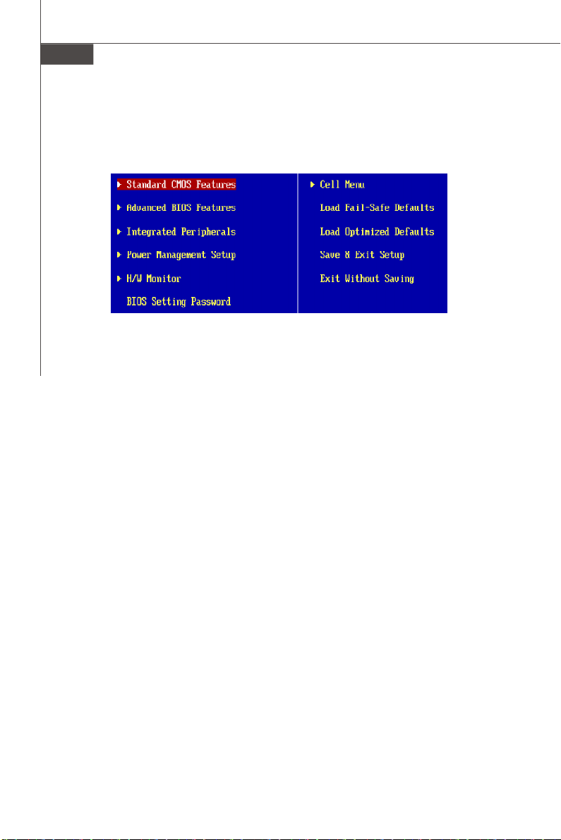
Carte mère MS-7527
Menu principal
Une fois entré dans l’unité de réglages AMI® ou AWARD® BIOS CMOS, le Menu principal
appaît sur l’écran. Le Menu Principal vous permet de sélectionner de dix foncions de
réglage et deux choix de sortie. Utilisez les touches de flèche pour sélectionner parmi
les objets et appuyez sur <Enter> pour accepter ou entrer dans le sous-menu.
Standard CMOS Features (Fonctions CMOS standard)
Utilisez ce menu pour les configurations du système de base, tel que l’heure, la date.
Advanced BIOS Features (Fonctions BIOS avancées)
Utilisez ce menu pour régler les objets des fonctions am éliorées spéciales.
Integrated Peripherals (Périphériques intégrés)
Utilisez ce menu pour définir vos régléges des périphériques intégrés.
Power Management Features (Fonctions de la gestion de l’énergie)
Utilisez ce menu pour définir vos réglages de la gesion de l’énergie.
H/W Monitor (Moniteur H/W)
Cette entrée indique l’état de santé de votre PC.
BIOS Setting Password (Mot de passe de réglage BIOS)
Utilisez ce menu pour régler le mot de passe du BIOS.
Cell Menu (Menu cell)
Utilisez ce menu pour définir vos réglages du contrôle de la fréquence/voltage et de
l’overclocking.
Load Fail-Safe Defaults (Défauts de sécurité de chargement intégrée)
Utilisez ce menu pour charger les valeur par défauts réglées par le vendeur de BIOS
afin de garantir la stabilité des performances du système.
Load Optimized Defaults (Chargement des réglages par défaut optimisés)
Utilisez ce menu pour charger les valeurs par défaut réglées par le fabricant de la carte
mère spécifiquement pour obtenir des performances optimales de la carte mère.
BIOS Setting Password (Mot de passe de réglage BIOS)
Utilisez ce menu pour régler le mot de passe.
Save & Exit Setup (Sauvegarder et quitter les réglages)
Sauvegardez les changements apportés au CMOS puis quittez les réglages.
Exit Without Saving (Quitter sans sauvegarder)
Abandonnez tous les changements et quittez les réglages.
Fr-20
Page 79

Quand vous entrez dans l’unité de réglages BIOS, suivez les procédures suivantes pour
l’utilisation générale.
1. Load Optimized Defaults (chargement des réglages par défaut optimisés) : Utilisez
les touches de contrôle (↑↓ ) afin de surligner le domaine Load Optimized Defaults
et appuyez sur <Enter> , le message suivant apparaîtra :
Choisir [Ok] et appuyer sur Enter chargera les valeurs défauts de BIOS pour un
système minimal plus stable.
2. Setup Date/ Time (Réglage de l’heure et de la date) : Choisissez Standard CMOS
Features et appuyez sur <Enter> afin d’entrer dans le menu Standard CMOS Features.
Ajustez la date et l’heure.
3. Save & Exit Setup (Sauvegarder et quitter les réglages) : Utilisez les touches de
contrôle (↑↓ ) afin de surligner le domaine de Save & Exit Setup et appuyez sur
<Enter> , le message suivant apparaîtra :
Choisir [Ok] et appuyer sur Enter afin de sauvegarder les configurations et l’unité de
réglages de quitter BIOS.
Important
Les configurations précédantes ne sont que pour l’utilisation générale. Si vous
avez besoin de réglages détaillés du BIOS, veuillez vous référer au manuel de
l’édition anglaise sur la page d’internet de MSI.
Français
Fr-21
Page 80

Carte mère MS-7527
4. Cell Menu Introduction (Introduction du Menu cell) : Ce menu est pour des utilisations
avancée destinée à overclocker la carte mère.
Important
Ne changez pas ces réglages sauf que vous connaissiez bien ces chipsets.
Current CPU/ DRAM Frequency (Fréquence actuelle du CPU/ DRAM)
Ces articles montrent les horloges actuelles de la vitesse du CPU et de la mémoire.
Lecture uniquement.
Intel EIST
La Technologie Enhanced Intel SpeedStep vous permet de configurer le niveau de
performance du microprocesseur si l’ordinateur fonctionne en batterie ou en
l’adapteur d’alimentation. Ce domaine apparaītra aprčs que vous installez le CPU
qui supporte la technologie de speedstep.
Adjust CPU FSB Frequency (MHz) (Ajustement de la fréquence du FSB
du CPU)
Cet artible vous permet de sélectionner la fr équence d’horloge du FSB du CPU (en
MHz).
Adjusted CPU Frequency (MHz) (Ajustement de la fréquence du CPU)
Il montre la fréquence ajustée du CPU (FSB x Ratio). Lecture uniquement.
Advance DRAM Configuration (Avancer les configurations du DRAM)
Appuyez sur <Enter> pour entrer dans le sous-menu.
Fr-22
Page 81

DRAM Timing Mode (Mode DRAM Timing)
Mis en [Enabled] rend DRAM CAS# Latency automatiquement déterminé par
BIOS basé sur les configurations sur le SPD (Serial Presence Detect) EEPROM
sur le moduole DRAM.
CAS Latency(CL) (Latence CAS)
Lorsque le mode DRAM Timing est mis en [Manual], ce domaine est ajustable.
Il contrôle la latence CAS, qui détermine le retard de timing (dans les cycles
d’horloge) avant que le SDRAM commence un ordre de lecture après l’avoir
reçu.
tRCD
Lorsque le mode DRAM Timing est mis en [Manual], ce domaine est ajustable.
Quand le DRAM est rafraîchi, les rangs et les colonnes sont tous adressés
séparément. Cet article vous permet de déterminer le timing de la transition de
RAS (row address strobe) à CAS (column address strobe). Le moins fonctionne
l’horloge, le plus vite est la performance de DRAM.
tRP
Lorsque le mode DRAM Timing est mis en [Manual], ce domaine est ajustable. Cet
article contrôle le numéro de cycles pour que le Row Address Strobe (RAS) soit
permit de précharger. S’il n’y a pas assez de temps pour que le RAS accumule son
charge avant le refraîchissement de DRAM, le refraîchissement peut être incomplet
et le DRAM peut échouer à retenir les données.Cet article applique seulement
quand le DRAM synchrone est installé dans le système.
tRAS
Lorsque le mode DRAM Timing est mis en [Manual], ce domaine est ajustable. Cet
article détermine le temps que le RAS prend pour lire ou écrire sur une cellule de
mémoire.
tRTP
Quand le DRAM Timing Mode est mis en [Manual], time interval between a
read and a precharge command.
Français
tRC
Lorsque le mode DRAM Timing est mis en [Manual], ce domaine est ajustable.
ce temps du cycle de rang détermine le numéro minimum du cycle d’horloge
dont un rang de mémoire a besoin afin de compléter un plein cycle, de
l’activation du rang jusqu’à la préparation du rang active.
tWR
Lorsque DRAM Timing Mode est mis en [Manual], Ce domaine est ajustable. Il
spécifie la quantité de retard (en cycles d’horloge) qui doit disparaître après la
fin d’une opération d’écriture valide, avant qu’une banque activée soit
préchargée. Ce retard sert à garantir que les données dans les buffers blancs
soient écrites sur les cellules mémoire avant le surgissement du précharge.
tRRD
Lorsque le mode DRAM Timing est mis en [Manual], ce domaine est ajustable.
Il spécifie le retard activité-à-activité de banques différentes. Le temps interval
entre une lecture et un ordre de précharge.
Fr-23
Page 82

Carte mère MS-7527
tWTR
Lorsque le DRAM Timing Mode est mis en [Manual], ce domaine est ajustable.
Cet article contrôle le Write Data dans le timing de mémoire Read Command
Delay. Cela constitue le numéro minimum de cycle d’horloge qui se déroule
entre la dernière opération blanche valide et le prochain ordre de lecture à la
même banque intégrée du dispositif DDR.
FSB/Memory Ratio
Cet article vous permet d’ajuster le FSB/Ratio de la mémoire.
Adjusted DRAM Frequency (MHz)
Il montre la fréquence de la mémoire DDR ajustée. Lecture uniquement.
Adjust PCI-E Frequency (MHz)
Cet domaine vous permet de sélectionner la fréquence de PCIE (en MHz).
Auto Disable DIMM/PCI Frequency
Lorsqu’il est activé, le système éteindra les horloges des fentes vides de PCI pour
réduire au minimum l’interface électromagnétique (EMI).
Spread Spectrum
Lorsque le clock generator de la carte mère fonctionne, les valeurs extrêmes (spikes)
créent des interférences électromagnétiques (EMI-Electromagnetic Interference). La
fonction Spread Spectrum réduit ces interférences en réglant les impultions. Si vous
n’avez pas de problème d’EMI ceci vous permet d’avoir une stabilité du système et
des performances optimales. Dans le cas contraire, choisissez Enabled pour réduire
les interférences. N’oubliez pas de désactiver cette fonction si vous voulez faire de
l’overclocking, parce que la moindre modification peut entraîner une accélération
temporaire d’horloge et ainsi votre processeur overclocké se verrouillera.
Important
1.Si vous n’avez pas de probl ème d’EMI, laissez l’option sur [Disabled] ceci
vous permet d’avoir une stabilité du système et des performances optimales.
Dans le cas contaire, choisissez Spread Spectrum pour réduire les EMI.
2.Plus la valeur Spread Spectrum est importante, plus les EMI sont réduites, et
le système devient moins stable. Pour la valeur Spread Spectrum la plus
convenable, veuillez consulter le règlement EMI local.
3.N’oubliez pas de désactiver la fonction Spread Spectrum si vous êtes en
train d’overclocker parce que même un battement léger peut causer un
accroissement temporaire de la vitesse de l’horloge qui verrouillera votre
processeur overclcké.
Fr-24
Page 83

Information de Logiciel
Sortez le pilote/ Service du CD, qui est inclus dans le paquet de la carte mère et
placez-le dans le CD-ROM.L’installation va automatiquement se déclencher, cliquez
sur le pilote ou sur l’usage et suivez le pop-up de l’écran pour accomplir l’installation.
Le pilote/Service CD contient :
Menu de pilote – Il montre les pilotes disponibles. Installez le pilote si vous le
souhaitez pour activer le dispositif.
Menu de services – Il montre les applications logicielles supportées par la carte mère.
Menu du site Web – Il vous indique les sites webs utiles.
Important
Veuillez consulter le site Web de MSI pour obtenir les derniers pilotes et BIOS
pour améliorer l’exécution du système de votre ordinateur.
Français
Fr-25
Page 84

G31M4
Руководство
пользователя
Русский
Русский
Ru-1
Page 85

MS-7527 Системная плата
Характеристики
Процессоры
- Процессоры Intel® Core2 Duo/ Pentium D/ Pentium 4 / Celeron D
Prescott LGA775 в конструктиве LGA775.
- Поддержка 4-конт вентилятора процессора с функцией
управления скоростью вращения.
(Для получения новых сведений о процессорах посетите сайт
http://global.msi.com.tw/index.php?func=cpuform)
FSB
- 800/1066/1333 МГЦ
Чипсет
- Северный мост: Intel® G31 chipset
- Южный мост: Intel® ICH7 chipset
Память
- DDR2 667/800 SDRAM (4ГБ Max)
- 4 слота DDR2 DIMM
(За дополнительной информацией о совместимых компонентах
посетите сайт http://global.msi.com.tw/index.php?func=testreport)
LAN (опционально)
- Поддержка Realtek® RTL8111C 10/100/1000 Мб/с
- Поддержка Realtek® RTL8101E 10/100 Мб/ с (опционально)
- Совместимость со спецификацией PCI 2.2
- Поддержка управления питанием ACPI
Ru-2
Аудио
- Интегрированный чипсет Realtek® ALC888
- 8-канальное аудио с гибким переназначением разъемов
- Совместим со спецификацией Vista Premium
IEEE 1394 (опционально)
- Интегрированный чипсет JMicron 381
- Скорость передачи данных до 400Мб/с
IDE
- 1 порт IDE на чипсете ICH7
- Поддержка режимов Ultra DMA 66/100
- Поддержка режимов работы PIO, Bus Master
SATA
- 4 порта SATA II на чипсете ICH7
- Поддержка скорости передачи данных до 3Гб/с
Page 86

Флоппи
- 1 флоппи порт
- Поддержка 1 FDD с 360КБ, 720КБ, 1.2МБ, 1.44МБ И 2.88МБ
Коннекторы
Задней панели
- 1 PS/2 порт мыши
- 1 PS/2 порт клавиатуры
- 1 последовательный порт (COM1)
- 1 порт VGA
- 1 параллельный порт поддерживает режимы SPP/EPP/ECP
- 4 порта USB 2.0
- 1 разъем RJ-45 LAN Jack
- 1 порт 1394 (опционально)
- 6 звуковых разъемов с гибким переназначением
Разъемы, установленные на плате
- 2 разъема USB 2.0
- 1 разъем CD-in
- 1 разъем SPDIF-Out
- 1 разъем IEEE 1394 (опционально)
- 1 разъем для аудио на передней панели
- 1 последовательноый разъем
- 1 разъем TPM (опционально)
- 1 разъем датчика открывания корпуса
Слоты
- 1 слот PCI Express x16
- 3 слота PCI
- Поддержка интерфейса PCI шины с питанием 3.3V/ 5V
Форм фактор
- Micro-ATX (24см X 24см)
Русский
Крепление
- 6 отверстий для крепления
Ru-3
Page 87

MS-7527 Системная плата
Mouse/
Keyboard,
p.Ru-16
JCI1,
p.Ru-11
Parallel Port,
p.Ru-16
Serial Port,
p.Ru-16
PWR1,
p.Ru-14
VGA Port,
p.Ru-16
CPU,
p.Ru-5
1394,
p.Ru-16
USB ports,
p.Ru-17
CPUFAN1,
p.Ru-9
LAN,
p.Ru-17
DDR2,
p.Ru-7
RS-Out
L-In
L-Out
CS-Out
Mic
SS-Out
Audio Port,
p.Ru-17
ATX1,
p.Ru-14
IDE1,
p.Ru-9
PCIE,
p.Ru-15
PCI,
p.Ru-15
JCD1,
p.Ru-12
JAUD1,
p.Ru-12
JCOM1,
p.Ru-11
JSP1,
p.Ru-12
FDD1,
p.Ru-9
J1394_1,
p.Ru-10
JTPM1,
p.Ru-12
JUSB1~2,
p.Ru-11
SYSFAN2,
p.Ru-9
SYSFAN1,
p.Ru-9
SATA1~4,
p.Ru-10
JFP1, JFP2,
p.Ru-10
JBAT1,
p.Ru-13
Руководство по размещению компонентов на системных
платах серии G31M4 (MS-7527 v1.X)
Ru-4
Page 88

Центральный процессор: CPU
Эта системная плата поддерживает процессор от Intel®. Для облегчения установки
процессора на ней установлен разъем под названием Socket 775. Если у вас нет
процессорного кулера, пожалуйста, свяжитесь с дилером с целью приобретения
и его установки до того, как включите компьютер.
Самую последнюю информацию о поддерживаемых процессорах можно
получить на сайте http://global.msi.com.tw/index.php?func=cpuform
Внимание
Перегрев
Перегрев может серьезно повредить центральный процессор и систему.
Чтобы уберечь процессор от перегрева, убедитесь в том, что
процессорный кулер работает нормально. Чтобы увеличить
теплорассеивание, убедитесь в том, что нанесен слой теплопроводящей
пасты (или теплопроводящей ленты) между процессором и радиатором.
Замена CPU
При замене CPU, во избежание его повреждения, обязательно
отключите источник питания или выньте вилку блока питания из
розетки.
Разгон
Эта системная плата поддерживает «разгон». Однако, убедитесь, что
компоненты системы способны работать в таких нестандартных
режимах. Не рекомендуется использовать продукт в режимах, не
соответствующих указанным в спецификациях.
Русский
Ru-5
Page 89

MS-7527 Системная плата
Установка процессора и вентилятора для Socket 775
1. Разъем процессора закрыт пластиковой крышкой, которая
защищает контакты разъема от повреждений и загрязнений. Если
процессор не установлен в разъем, необходимо всегда закрывать
его пластиковой крышкой для защиты от пыли и повреждений.
2. Снимите крышку, подняв ее с одной стороны.
3. Откроются контакты разъема.
4. Потяните за рычаг крепления.
5. Поднимите рычаг и откройте металлическую крышку для
установки процессора.
6. Убедившись в правильной ориентации процессора, положите
процессор в разъем. Обратите внимание, что выемки на процессоре
должны соответствовать выступам на процессорном разъеме.
7. Визуально проверьте правильность установки процессора в
разъем. Если процессор установлен неправильно, то выньте
процессор и переустановите.
8. Опустите металлическую крышку механизма крепления.
9. Аккуратно опустите рычаг на крышку механизма крепления и
зафиксируйте его. Для фиксации рычага в механизме крепления
предусмотрен специальный выступ.
10.Совместите отверстия системной платы с защелками крепления
вентилятора. Прижмите радиатор с вентилятором к процессору
и проследите, чтобы четыре защелки вошли в отверстия
системной платы.
11.Нажмите на четыре защелки и закрепите вентилятор. Затем
поверните фиксаторы защелок (направление поворота указано
на вентиляторе) и закрепите их.
12.Переверните системную плату и убедитесь, что защелки надежно удерживают
вентилятор.
alignment key
Внимание
1. Информацию об установленном процессоре смотрите в BIOS.
2. Если процессор не установлен, всегда закрывайте разъем пластиковой
крышкой для предотвращения поломок и попадания в него грязи и пыли.
3. Фото системной платы, размещенные в этой части, приведены только
для демонстрации установки вентилятора. Общий вид системной платы
зависит от модели, купленной вами.
Ru-6
Page 90

Память
1
2
3
Installed
Слоты DIMM используются для установки модулей памяти.
За дополнительной информацией о совместимых компонентах посетите сайт
http://global.msi.com.tw/index.php?func=testreport
DDR2
240-pin, 1.8V
64x2=128 pin56x2=112 pin
Правила установки модулей памяти для работы в
двухканальном режиме
В двухканальном режимемодули памяти могут передавать и принимать данные
по 2 шинам одновременно. При использовании двухканального режима
производительность системы повышается. Ниже приведены правила
заполнения слотов памяти для работы в двухканальном режиме.
DIMM1
DIMM2
DIMM3
DIMM4
DIMM1
DIMM2
DIMM3
DIMM4
Русский
DIMM1
DIMM2
DIMM3
DIMM4
Empty
Ru-7
Page 91

MS-7527 Системная плата
Установка модулей памяти
1. Модули памяти имеют только одну прорезь в середине. Модуль войдет в
разьем только при правильной ориентации.
2. Вставьте модуль в DIMM слот в вертикальном направлении. Затем нажмите на
него, чтобы золоченые контакты глубоко погрузились в DIMM слот. Если модуль
памяти вставлен правильно, то пластиковые защелки на обоих концах закроются
автоматически.
Внимание
Золотые контакты едва видны, если модули памяти правильно размещены
в DIMM слоте.
3. Вручную убедитесь, что модуль закреплен в слоте DIMM защелками с обеих
сторон.
Volt
Notch
Important
- Модули DDR2 не взаимозаменяемы с модулями DDR, и стандарт DDR2
не имеет обратной совместимости. Следует установить модули
памяти DDR2 в разъемы DDR2 DIMM.
- Для работы в двухканальном режиме убедитесь, что в разъемах
разных каналов у вас установлены модлуи одного типа и одинаковой
емкости.
- Чтобы система загрузилась, вначале установите модули в разъем
DIMM1.
Ru-8
Page 92

Коннекторы, перемычки, разъемы
Разъемы питания вентиляторов: CPUFAN1, SYSFAN1/2
Разъемы питания вентиляторов поддерживают вентиляторы с питанием +12В.
Вентилятор процессора поддерживает функцию Smart FAN . При подключении
необходимо помнить, что красный провод подключается к шине +12В, черный - к
земле GND. Если на системной плате установлена микросхема аппаратного
мониторинга, необходимо использовать специальные вентиляторы с датчиками
скорости для реализации функции управления вентиляторами.
Control
SENSOR
+12V
GND
CPUFAN1
SENSOR or NC
+12V
GND
SYSFAN1/2
Внимание
1. Чтобы узнать о моделях подходящих вентиляторов обратитесь,пожалуйста,
на официальный веб сайт или проконсультируйтесь с продавцом .
2. CPUFAN поддерживает функцию управления вентилятором. Для
автоматического контроля скорости вентилятора процессора, зависящей
от температуры процессора, можно установить Dual Core Center.
3. Разъем CPUFAN поддерживает вентиляторы как с 3, так и с 4
контактами.
Разъем FDD: FDD1
Разъем поддерживает FDD емкостью 360Kб, 720Kб, 1.2Mб, 1.44Mб или 2.88Mб.
Разъем IDE: IDE1
Разъем поддерживает жесткий диск IDE, дополнительное дисковое устройство и
другие устройства с интерфейсом IDE.
Русский
Внимание
При подключении двух устройств в одном кабеле, следует установить
устройства в режим Master/ Slave посредством установки перемычки. За
инструкциями обратитесь к документации изготовителя устройства.
Ru-9
Page 93

MS-7527 Системная плата
Разъем Serial ATA: SATA1~4
Данный разъем является высокоскоростным портом интерфейса Serial ATA. Любой
разъем Serial ATA может соединяться с одним устройством Serial ATA.
SATA4
SATA2
SATA1
SATA3
Внимание
Избегайте, пожалуйста, резких изгибов кабеля Serial ATA. В противном
случае могут возникнуть потери данных при передаче.
Коннекторы на передней панели: JFP1, JFP2
Эти коннекторы используются для подключения кнопок и индикаторов,
расположенных на передней панели корпуса. Коннектор JFP1 соответствует
руководству Intel® Front Panel I/O Connectivity Design.
9
Power
Switch++
Power
LED
10
-
+
Reset
-
2
JFP1
Switch
-
HDD
LED
1
Speaker
8
7
+
-
Power
+
2
JFP2
LED
1
-
РазъемIEEE1394 (Зелёный): J1394_1 (опционально)
Этот коннектор позволяет подключить порты IEEE 1394 на выносной планке
IEEE1394.
IEEE1394 Bracket
(опционально)
Ground
TPB-
TPA-
Cable power
2
1
Ground
10
9
TPA+
TPB+
Ground
Key (no pin)
Cable power
Ru-10
Page 94

Выносные порты USB (Желтый коннектор ): JUSB1~2
Разъем, соответствует спецификации Intel® I/O Connectivity Design, идеально
подходит для подключения таких высокоскоростных периферийных устройств,
как USB HDD, цифровые камеры, MP3 плееры, принтеры, модемы и им подобные.
USB 2.0 Bracket
(опционально)
2
1
VCC
VCC
USBOC
USB1-
USB1+
GND
10
9
GND
USB0-
USB0+
Key (no pin)
Внимание
Помните, что во избежание повреждений, контакты VCC и GND должны
быть правильно подключены.
Разъем датчика открывания корпуса: JCI1
К этому коннектору подключается кабель датчика, установленного в корпусе.
При открывании корпуса его механизм активизируется. Система запоминает это
событие и выдает предупреждение на экран. Предупреждение можно отключить в
настройках BIOS.
GND2
1
CINTRU
Разъем последовательного порта: JCOM1
Разъем - это высокоскоростной последовательный порт связи 16550A с 16- битной
передачей FIFO. К этому разъему можно непосредственно подключить
последовательное устройство.
SIN
CTS
DSR
2
1
DCD
10
9
RI
RTS
SOUT DTR
Ground
Ru-11
Русский
Page 95

MS-7527 Системная плата
Разъем CD-In: JCD1
Этот коннектор предназначен для подключения внешнего входа аудио.
GND R
L
Разъем TPM модуля: JTPM1(опционально)
Данный разъем подключается к модулю TPM (Trusted Platform Module)
(опционально). За более подробной информацией и назначениями обращайтесь
к описанию модуля TPM.
3V dua l / 3V _ST B
VC C3
SIR Q
VC C5
Ke y(n o pin )
GN D
GN D
2
1
14
13
LCLK
LAD0
LAD1
LAD2
LAD3
LR ST#
LF RA ME #
Разъем выхода S/PDIF: JSP1
Этот разъем используется для подключения интерфейса S/PDIF (Sony & Philips
Digital Interconnect Format) для передачи звука в цифровом формате.
VCC
SPDIF
GND
SPDIF Bracket
(опционально)
Выносной разъем аудио (соответсвует спецификацией Azalia): JAUD1
Этот коннектор позволяет подключить выносной разъем аудио на передней панели
и соответствует руководству Intel® Front Panel I/O Connectivity Design.
M IC_ J D
NC (N o pi n)
Gr oun d
Pr esen ce#
2
1
MI C _ L
LI NE ou t_ JD
10
9
M IC _R
Fr on t_J D
LIN E ou t_L
LI NE ou t_ R
Ru-12
Page 96

Перемычка очистки CMOS: JBAT1
На плате установлена CMOS память с питанием от батарейки, хранящая данные
о конфигурации системы. С помощью памяти CMOS, система автоматически
загрузится каждый раз при включении. Если у вас возникает необходимость
сбросить конфигурацию системы (очистить CMOS), воспользуйтесь этой
перемычкой.
3
3
1
1
Keep Data
1
Clear Data
Внимание
Очистка CMOS производится соединением контактов 2-3 при отключенной
системе. Затем следует вернуться к соединению контактов 1-2. Избегайте
очистки CMOS при работающей системе: это повредит системную плату .
Русский
Ru-13
Page 97

MS-7527 Системная плата
Подключение источника питания: ATX1
Перед подключением разъема питания, во избежание повреждений обязательно
убедитесь, что все компоненты установлены правильно. Все разъемы питания
должны быть подключены к блоку питания ATX для обеспечения стабильной
работы системной платы.
24-контактный разъем питания: ATX1
Этот разъем позволяет подключить 24-контактный разъем питания ATX. Перед
подключением источника питания убедитесь, что его контакты и разъем на плате
правильно сориентированы. Затем плотно вставьте его в разъем на системной
плате.
Вы также можете использовать 20-контактный ATX блок питания.
1224
+3.3V
+12V
+12V
5VSB
PWR OK
GND
+5V
GND
+5V
GND
+3.3V
+3.3V
GND
+5V
+5V
+5V
NC
GND
GND
GND
PS-ON#
GND
-12V
+3.3V
1
13
Разъем питания ATX 12V (2x2-Pin): PWR1
Этот разъем питания 12В используется для обеспечения питания процессора.
4 2
GND12V
12V
GND
1
3
Ru-14
Page 98

Слот PCI Express (x16/ x1)
Слот PCI Express поддерживает карты расширения интерфейса PCI Express.
Слот PCI Express x16
Слот PCI Express x 1
Слот PCI (Peripheral Component Interconnect)
Слот PCI позволяет установить карты LAN, SCSI, USB и другие дополнительные
карты расширения, которые соответствуют спецификации PCI.
Внимание
Русский
Перед установкой или извлечением карт расширения убедитесь, что кабель
питания отключен от электрической сети. Прочтите документацию на
карту расширения и выполните необходимые аппаратные или програмные
установки для данной платы, такие как перемычки, переключатели или
конфигурацию BIOS.
Ru-15
Page 99

MS-7527 Системная плата
Задняя панель
Разъемы мыши/клавиатуры
Стандартные разъемы DIN PS/2® для подключения мыши/клавиатуры с
интерфейсом PS/2®.
Разъем PS/2 для мыши (6-контактная зеленая
розетка)
Разъем PS/2 для клавиатуры (6-контактная
фиолетовая розетка)
Разъем параллельного порта
Параллельный порт - это стандартный порт для принтера. Он поддерживает режимы
EPP (усовершенствованный параллельный порт) и ECP (параллельный порт с
дополнительными возможностями).
13 1
(25-контактная розетка)
1425
Разъем последовательного порта
Это высокоскоростной последовательный порт связи 16550A с 16-битной
передачей FIFO. К этому разъему можно непосредственно подключить мышь для
последовательного порта или другое устройство.
1 5
(9-контактная вилка)
6 9
Порт VGA
Разъем DB15 для подключения монитора.
15
(15-контактная розетка DIN)
1115
Порт 1394
Порт 1394 на задней панели позволяет подключать устройства с интерфейсом
IEEE1394.
Ru-16
Page 100

Разъем LAN
Стандартный разъем RJ-45 для подключения к локальной вычислительной сети
(LAN). К нему подключается кабель локальной сети.
LED Цвет Состояние LED Описание
Нет LAN соединение не установлено.
Лев. Оранж. Есть (постоянно) LAN соединение установлено.
Есть ( пульсирует) Связъ с другим компьютером по LAN.
Зелен. Нет Скорость передачи 10 Мб/с.
Прав. Есть Скорость передачи 100 Мб/с.
Оранж. Есть Скорость передачи 1000 Мб/с.
Порт USB
USB порт (Universal Serial Bus) позволяет подключать такие USB устройства, как
клавиатура, мышь и т.д.
Аудио разъемы
Эти разъемы используются для подключения звуковых устройств. Разъемы,
выполняющие разные функции, имеют различные цвета.
Русский
Вход аудио (Голубой) - Линейный вход для подключения внешнего CD
проигрывателя, магнитофона или других звуковых устройств.
Выход аудио (Зеленый) - Линейный выход для подключения наушников или колонок.
Микрофон (Розовый) - Разъем для подключения микрофона.
Выход RS (Черный) - Выход на задние колонки в режиме 4/ 5.1/ 7.1.
Выход CS (Оранжевый) -Выход на центральную колонку и сабвуфер в режиме 5.1/ 7.1.
Выход SS (Серый) - Выход на боковые колонки в режиме 7.1.
Ru-17
 Loading...