

Page 1
FCC-B Radio Frequency Interference Statement
This equipment has been tested and found to comply with the limits for a class B digital
device, pursuant to part 15 of the FCC rules. These limits are designed to provide
reasonable protection against harmful interference in a residential installation. This
equipment generates, uses and can radiate radio frequency energy and, if not installed and
used in accordance with the instruction manual, may cause harmful interference to radio
communications. However, there is no guarantee that interference will occur in a particular
installation. If this equipment does cause harmful interference to radio or television
reception, which can be determined by turning the equipment off and on, the user is
encouraged to try to correct the interference by one or more of the measures listed below.
n Reorient or relocate the receiving antenna.
n Increase the separation between the equipment and receiver.
n Connect the equipment into an outlet on a circuit different from that to which the
receiver is connected.
n Consult the dealer or an experienced radio/ television technician for help.
Notice 1
The changes or modifications not expressly approved by the party responsible for
compliance could void the user’s authority to operate the equipment.
Notice 2
Shielded interface cables and A.C. power cord, if any, must be used in order to comply with
the emission limits.
VOIR LA NOTICE D’NSTALLATION AVANT DE RACCORDER AU RESEAU.
Micro-Star International
MS-7529
G52-75291X1
Page 2

Copyright Notice
The material in this document is the intellectual property of MICRO-STAR INTERNATIONAL.
We take every care in the preparation of this document, but no guarantee is given as to the
correctness of its contents. Our products are under continual improvement and we reserve
the right to make changes without notice.
Trademarks
All trademarks are the properties of their respective owners.
AMD®, Athlon™ Athlon™XP, Thoroughbred™ and Duron™ are registered trademarks of
AMD® Corporation.
Intel® and Pentium® are registered trademarks of Intel Corporation.
PS/2 and OS®/2 are registered trademarks of International Business Machines Corporation.
Microsoft® is a registered trademark of Microsoft Corporation. Windows® 98/2000/NT/XP are
registered trademarks of Microsoft Corporation.
NVIDIA®, the NVIDIA logo, DualNet, and nForce are registered trademarks or trademarks of
NVIDIA® Corporation in the United States and/or other countries.
Netware® is a registered trademark of Novell, Inc.
Award® is a registered trademark of Phoenix Technologies Ltd.
AMI® is a registered trademark of American Megatrends Inc.
Kensington and MicroSaver are registered trademarks of the Kensington Technology
Group.
PCMCIA and CardBus are registered trademarks of the Personal Computer Memory Card
International Association.
Revision History
Revision Revision History Date
V1.0 First release March 2008
Page 3
Safety Instructions
n Always read the safety instructions carefully.
n Keep this User Manual for future reference.
n Keep this equipment away from humidity.
n Lay this equipment on a reliable flat surface before setting it up.
n The openings on the enclosure are for air convection hence protects the equipment
from overheating. Do not cover the openings.
n Make sure the voltage of the power source and adjust properly 110/220V before
connecting the equipment to the power inlet.
n Place the power cord such a way that people can not step on it. Do not place
anything over the power cord.
n Always Unplug the Power Cord before inserting any add-on card or module.
n All cautions and warnings on the equipment should be noted.
n Never pour any liquid into the opening that could damage or cause electrical shock.
n If any of the following situations arises, get the equipment checked by a service
personnel:
- The power cord or plug is damaged.
- Liquid has penetrated into the equipment.
- The equipment has been exposed to moisture.
- The equipment does not work well or you can not get it work according to User
Manual.
- The equipment has dropped and damaged.
- The equipment has obvious sign of breakage.
n Do not leave this equipment in an environment unconditioned, storage temperature
above 60° C (140°F), it may damage the equipment.
CAUTION: Danger of explosion if battery is incorrectly replaced. Replace only with
the same or equivalent type recommended by the manufacturer.
Page 4

WEEE Statement
ENGLISH
To protect the global environment and as an environmentalist, MSI must remind you
that...
Under the European Union ("EU") Directive on Waste Electrical and Electronic Equipment, Directive
2002/96/EC, which takes effect on August 13, 2005, products of "electrical and electronic equipment"
cannot be discarded as municipal waste anymore and manufacturers of covered electronic equipment will
be obligated to take back such products at the end of their useful life. MSI will comply with the product take
back requirements at the end of life of MSI-branded products that are sold into the EU. You can return
these products to local collection points.
DEUTSCH
Hinweis von MSI zur Erhaltung und Schutz unserer Umwelt
Gemäß der Richtlinie 2002/96/EG über Elektro- und Elektronik-Altgeräte dürfen Elektro- und
Elektronik-Altgeräte nicht mehr als kommunale Abfälle entsorgt werden. MSI hat europaweit
verschiedene Sammel- und Recyclingunternehmen beauftragt, die in die Europäische Union in Verkehr
gebrachten Produkte, am Ende seines Lebenszyklus zurückzunehmen. Bitte entsorgen Sie dieses
Produkt zum gegebenen Zeitpunkt ausschliesslich an einer lokalen Altgerätesammelstelle in Ihrer Nähe.
FRANÇAIS
En tant qu’écologiste et afin de protéger l’environnement, MSI tient à rappeler ceci...
Au sujet de la directive européenne (EU) relative aux déchets des équipement électriques et
électroniques, directive 2002/96/EC, prenant effet le 13 août 2005, que les produits électriques et
électroniques ne peuvent être déposés dans les décharges ou tout simplement mis à la poubelle. Les
fabricants de ces équipements seront obligés de récupérer certains produits en fin de vie. MSI prendra en
compte cette exigence relative au retour des produits en fin de vie au sein de la communauté européenne.
Par conséquent vous pouvez retourner localement ces matériels dans les points de collecte.
РУССКИЙ
Компания MSI предпринимает активные действия по защите окружающей среды, поэтому
напоминаем вам, что....
В соответствии с директивой Европейского Союза (ЕС) по предотвращению загрязнения
окружающей среды использованным электрическим и электронным оборудованием (директива
WEEE 2002/96/EC), вступающей в силу 13 августа 2005 года, изделия, относящиеся к
электрическому и электронному оборудованию, не могут рассматриваться как бытовой мусор,
поэтому производители вышеперечисленного электронного оборудования обязаны принимать его
для переработки по окончании срока службы. MSI обязуется соблюдать требования по приему
продукции, проданной под маркой MSI на территории EC, в переработку по окончании срока
службы. Вы можете вернуть эти изделия в специализированные пункты приема.
ESPAÑOL
MSI como empresa comprometida con la protección del medio ambiente, recomienda:
Bajo la directiva 2002/96/EC de la Unión Europea en materia de desechos y/o equipos electrónicos, con
fecha de rigor desde el 13 de agosto de 2005, los productos clasificados como "eléctricos y equipos
electrónicos" no pueden ser depositados en los contenedores habituales de su municipio, los fabricantes
de equipos electrónicos, están obligados a hacerse cargo de dichos productos al termino de su período
de vida. MSI estará comprometido con los términos de recogida de sus productos vendidos en la Unión
Europea al final de su periodo de vida. Usted debe depositar estos productos en el punto limpio
establecido por el ayuntamiento de su localidad o entregar a una empresa autorizada para la recogida de
estos residuos.
NEDERLANDS
Om het milieu te beschermen, wil MSI u eraan herinneren dat….
De richtlijn van de Europese Unie (EU) met betrekking tot Vervuiling van Electrische en Electronische
producten (2002/96/EC), die op 13 Augustus 2005 in zal gaan kunnen niet meer beschouwd worden als
vervuiling.
Fabrikanten van dit soort producten worden verplicht om producten retour te nemen aan het eind van hun
levenscyclus. MSI zal overeenkomstig de richtlijn handelen voor de producten die de merknaam MSI
dragen en verkocht zijn in de EU. Deze goederen kunnen geretourneerd worden op lokale
inzamelingspunten.
Page 5

SRPSKI
Da bi zaštitili prirodnu sredinu, i kao preduzeće koje vodi računa o okolini i prirodnoj sredini, MSI mora da
vas podesti da…
Po Direktivi Evropske unije ("EU") o odbačenoj ekektronskoj i električnoj opremi, Direktiva 2002/96/EC,
koja stupa na snagu od 13. Avgusta 2005, proizvodi koji spadaju pod "elektronsku i električnu opremu" ne
mogu viš e biti odbačeni kao običan otpad i proizvođ ači ove opreme biće prinuđeni da uzmu natrag ove
proizvode na kraju njihovog uobičajenog veka trajanja. MSI ć e poštovati zahtev o preuzimanju ovakvih
proizvoda kojima je istekao vek trajanja, koji imaju MSI oznaku i koji su prodati u EU. Ove proizvode
možete vratiti na lokalnim mestima za prikupljanje.
POLSKI
Aby chronić nasze środowisko naturalne oraz jako firma dbająca o ekologię, MSI przypomina, że...
Zgodnie z Dyrektywą Unii Europejskiej ("UE") dotyczącą odpadów produktów elektrycznych i
elektronicznych (Dyrektywa 2002/96/EC), która wchodzi w życie 13 sierpnia 2005, tzw. “produkty oraz
wyposażenie elektryczne i elektroniczne " nie mogą być traktowane jako śmieci komunalne, tak więc
producenci tych produktów będą zobowiązani do odbierania ich w momencie gdy produkt jest
wycofywany z użycia. MSI wypełni wymagania UE, przyjmując produkty (sprzedawane na terenie Unii
Europejskiej) wycofywane z użycia. Produkty MSI będzie można zwracać w wyznaczonych punktach
zbiorczych.
TÜRKÇE
Çevreci özelliğiyle bilinen MSI dünyada çevreyi korumak için hatırlatır:
Avrupa Birliği (AB) Kararnamesi Elektrik ve Elektronik Malzeme Atığı, 2002/96/EC Kararnamesi altında 13
Ağustos 2005 tarihinden itibaren geçerli olmak üzere, elektrikli ve elektronik malzemeler diğer atıklar gibi
çöpe atılamayacak ve bu elektonik cihazların üreticileri, cihazların kullanım süreleri bittikten sonra ürünleri
geri toplamakla yükümlü olacaktır. Avrupa Birliği’ne satılan MSI markalı ürünlerin kullanım süreleri
bittiğinde MSI ürünlerin geri alınması isteği ile işbirliği içerisinde olacaktır. Ürünlerinizi yerel toplama
noktalarına bırakabilirsiniz.
ČESKY
Záleží nám na ochraně životního prostředí - společnost MSI upozorňuje...
Podle směrnice Evropské unie ("EU") o likvidaci elektrických a elektronických výrobků 2002/96/EC platné
od 13. srpna 2005 je zakázáno likvidovat "elektrické a elektronické výrobky" v běžném komunálním
odpadu a výrobci elektronických výrobků, na které se tato směrnice vztahuje, budou povinni odebírat
takové výrobky zpět po skončení jejich životnosti. Společnost MSI splní požadavky na odebírání výrobků
značky MSI, prodávaných v zemích EU, po skončení jejich životnosti. Tyto výrobky můžete odevzdat v
mí stních sběrnách.
MAGYAR
Annak érdekében, hogy környezetünket megvédjük, illetve környezetvédőként fellépve az MSI
emlékezteti Önt, hogy ...
Az Európai Unió („EU") 2005. augusztus 13-án hatályba lépő, az elektromos és elektronikus
berendezések hulladékairól szóló 2002/96/EK irányelve szerint az elektromos és elektronikus
berendezések többé nem kezelhetőek lakossági hulladékként, és az ilyen elektronikus berendezések
gyártói kötelessé válnak az ilyen termékek visszavételére azok hasznos élettartama végén. Az MSI
betartja a termékvisszavétellel kapcsolatos követelményeket az MSI márkanév alatt az EU-n belül
értékesített termékek esetében, azok élettartamának végén. Az ilyen termékeket a legközelebbi
gyűjtőhelyre viheti.
ITALIANO
Per proteggere l’ambiente, MSI, da sempre amica della natura, ti ricorda che….
In base alla Direttiva dell’Unione Europea (EU) sullo Smaltimento dei Materiali Elettrici ed Elettronici,
Direttiva 2002/96/EC in vigore dal 13 Agosto 2005, prodotti appartenenti alla categoria dei Materiali
Elettrici ed Elettronici non possono più essere eliminati come rifiuti municipali: i produttori di detti materiali
saranno obbligati a ritirare ogni prodotto alla fine del suo ciclo di vita. MSI si adeguerà a tale Direttiva
ritirando tutti i prodotti marchiati MSI che sono stati venduti all’interno dell’Unione Europea alla fine del
loro ciclo di vita. È possibile portare i prodotti nel più vicino punto di raccolta.
Page 6

Table of Content
English...........................1
Français.........................13
Deutsch .........................25
Русском.........................39
简体中文 ........................53
繁體中文 ........................65
日本語............................77
Page 7
1
INTRODUCTION
Thank you for choosing the G31M3 V2 Series (MS-7529 v1.x) Micro-ATX mainboard. The
G31M3 V2 Series are based on Intel® G31 & Intel® ICH7 chipsets for optimal system
efficiency. Designed to fit the advanced Intel® Core
TM
2 Duo/ Core
TM
2 Quad/ Pentium
Dual-Core E2XXX and Celeron 4XXX/ Wolfdale Series LGA 775 processor, the G31M3 V2
Series deliver a high performance and professional desktop platform solution.
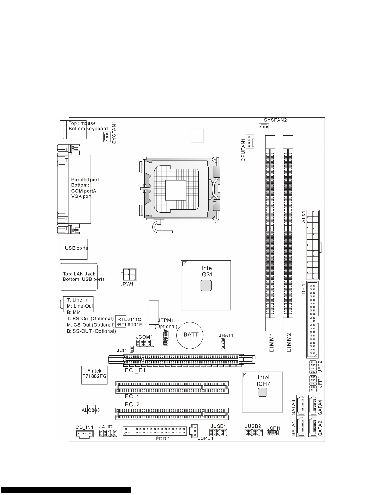
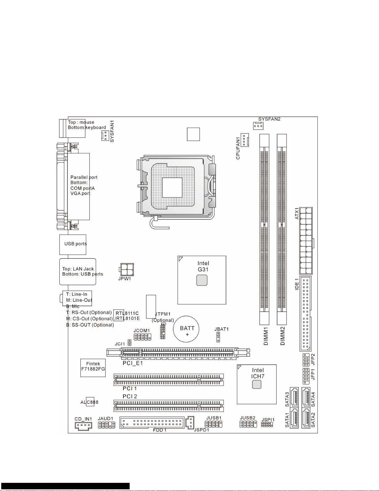
Layout
Page 8

2
SPECIFICATIONS
Processor Support
l Supports Intel® Core
TM
2 Duo/ Core
TM
2 Quad/ Pentium Dual-Core E2XXX and Celeron
4XXX/ Wolfdale Series processor in LGA 775 package.
l Supports 4 pin CPU fan pin-header with Fan speed Control
l Supports TDP Max. 95W
(For the latest information about CPU, please visit:
http://global.msi.com.tw/index.php?func=cpuform)
Supported FSB
l 800/ 1066/ 1333 MHz
Chipset
l North Bridge: Intel® G31 chipset
l South Bridge: Intel® ICH7 chipset
Memory Support
l DDR2 667/ 800 SDRAM (4GB Max)
l 2 DDR2 DIMMs (240 pin/ 1.8V)
(For more information on compatible components, please visit:
http://global.msi.com.tw/index.php?func=testreport)
LAN(Optional)
l Supports Realtek® RTL8111C 10/100/1000 Mbps
l Supports Realtek® RTL8101E 10/100 Mbps (optional)
l Compliance with PCI 2.2
l Supports ACPI Power Management
Audio
l Chip integrated by Realtek® ALC888
l Flexible 8-channel audio with jack sensing
l Compliant with Vista Premium
IDE
l 1 IDE port by ICH7
l Supports Ultra DMA 66/100 mode
l Supports PIO, Bus Master operation mode
SATA
l 2 SATA II ports by ICH7
l Supports 4 SATA II devices
l Supports storage and data transfers at up to 3Gb/s
Floppy
l 1 floppy port
l Supports 1 FDD with 360KB, 720KB, 1.2MB, 1.44MB and 2.88 MB
Page 9

3
TPM (Optional)
l Supports TPM
Connectors
l Back panel
- 1 PS/2 mouse port
- 1 PS/2 keyboard port
- 1 serial port (COM1)
- 1 VGA port
- 1 parallel port supporting SPP/EPP/ECP mode
- 4 USB 2.0 Ports
- 1 RJ-45 LAN jack
- 3/6 flexible audio jacks(optional)
l On-Board Pinheaders / Connectors
- 2 USB 2.0 pinheaders
- 1 CD-In connector
- 1 S/PDIF-Out pinheader
- 1 Front Panel Audio pinheader
- 1 serial port connector
- 1 TPM connector (optional)
- 1 chassis intrusion switch pinheader
- 1 SPI Debugging connector
Slots
l 1 PCI Express x16 slot
l 2 PCI slots
l Support 3.3V / 5V PCI bus Interface
Form Factor
l Micro-ATX (24.4 cm X 19.3 cm)
Mounting
l 6 mounting holes
Important:
To reach the 8-channel sound effect, the 7th and 8th channels must be outputted from front
panel (pinheader) if you purchase the mainboard with 3 audio jacks.
Page 10

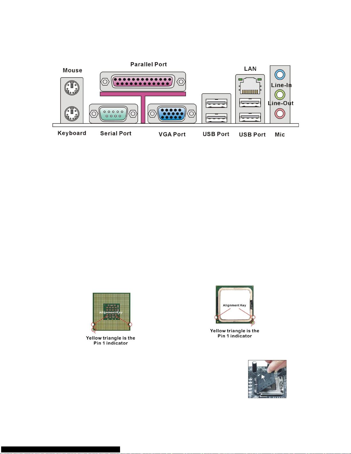
4
REAR PANEL
The rear panel provides the following connectors:
HARDWARE SETUP
This chapter tells you how to install the CPU, memory modules, and expansion cards, as
well as how to setup the jumpers on the mainboard. It also provides the instructions on
connecting the peripheral devices, such as the mouse, keyboard, etc. While doing the
installation, be careful in holding the components and follow the installation procedures.
CPU & Cooler Installation Procedures for LGA775
When you are installing the CPU, make sure the CPU has a cooler attached on the top to
prevent overheating. Meanwhile, do not forget to apply some thermal paste on CPU before
installing the heat sink/cooler fan for better heat dispersion.
Follow the steps below to install the CPU & cooler correctly. Wrong installation will cause the
damage of your CPU & mainboard.
Introduction to LGA 775 CPU
The pin-pad side of LGA 775 CPU.
The surface of LGA 775 CPU.
1. The CPU socket has a plastic cap on it to protect the contact
from damage. Before you have installed the CPU, always
cover it to protect the socket pin.
2. Remove the cap from lever hinge side.
3. The pins of socket reveal.
4. Open the load lever.
5. Lift the load lever up and open the load plate.
6. After confirming the CPU direction for correct mating, put
down the CPU in the socket housing frame. Be sure to grasp
Page 11
5
on the edge of the CPU base. Note that the alignment keys
are matched.
7. Visually inspect if the CPU is seated well into the socket. If
not, take out the CPU with pure vertical motion and reinstall.
8. Cover the load plate onto the package.
9. Press down the load lever lightly onto the load plate, and
then secure the lever with the hook under retention tab.
10. Align the holes on the mainboard with the cooler. Push down
the cooler until its four clips get wedged into the holes of the
mainboard.
11. Press the four hooks down to fasten the cooler. Then rotate
the locking switch (refer to the correct direction marked on it)
to lock the hooks.
12. Turn over the mainboard to confirm that the clip-ends are
correctly inserted.
Important:
Read the CPU status in BIOS.
Whenever CPU is not installed, always protect your CPU socket pin with the plastic cap
covered to avoid damaging.
Mainboard photos shown in this section are for demonstration of the CPU/cooler installation
only. The appearance of your mainboard may vary depending on the model you purchase.
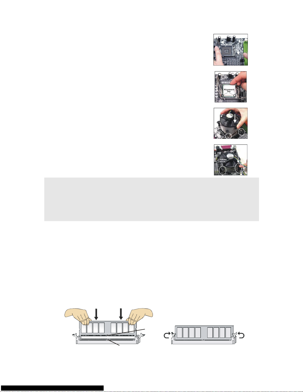
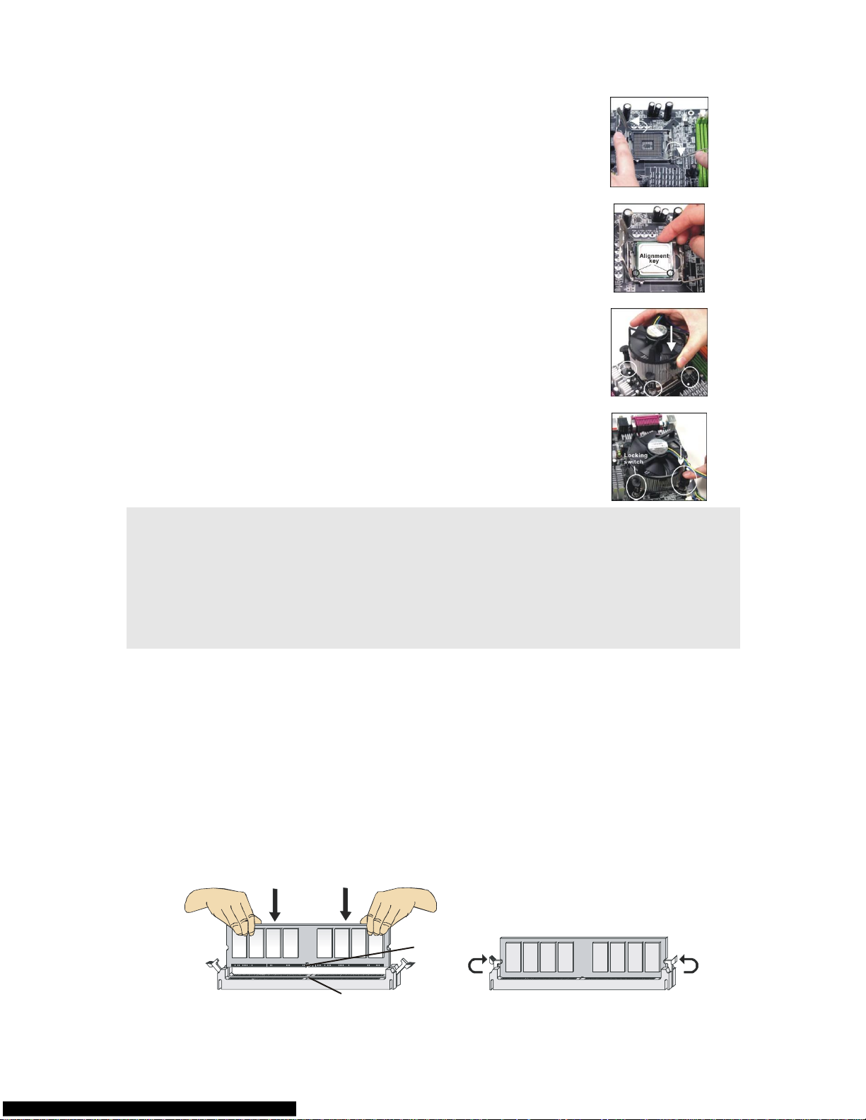
Installing Memory Modules
1. The memory module has only one notch on the center and will only fit in the right
orientation.
2. Insert the memory module vertically into the DIMM slot. Then push it in until the
golden finger on the memory module is deeply inserted in the DIMM slot. You can
barely see the golden finger if the memory module is properly inserted in the DIMM
slot. The plastic clip at each side of the DIMM slot will automatically close when the
memory module is properly seated.
3. Manually check if the memory module has been locked in place by the DIMM slot
clips at the sides.
Volt
Notch
Page 12
6
Important:
DDR2 memory modules are not interchangeable with DDR and the DDR2 standard is not
backwards compatible. You should always install DDR2 memory modules in the DDR2
DIMM slots.
To enable successful system boot-up, always insert the memory modules into the DIMM1
first.
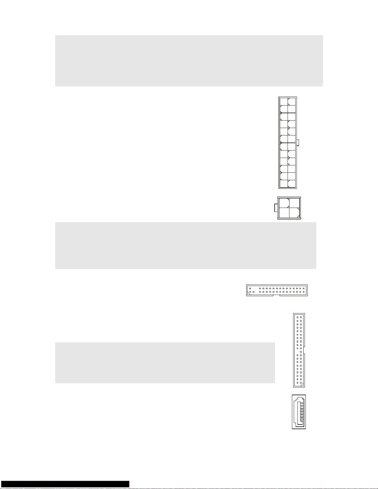
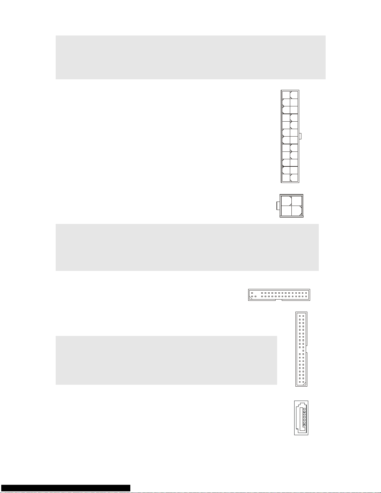
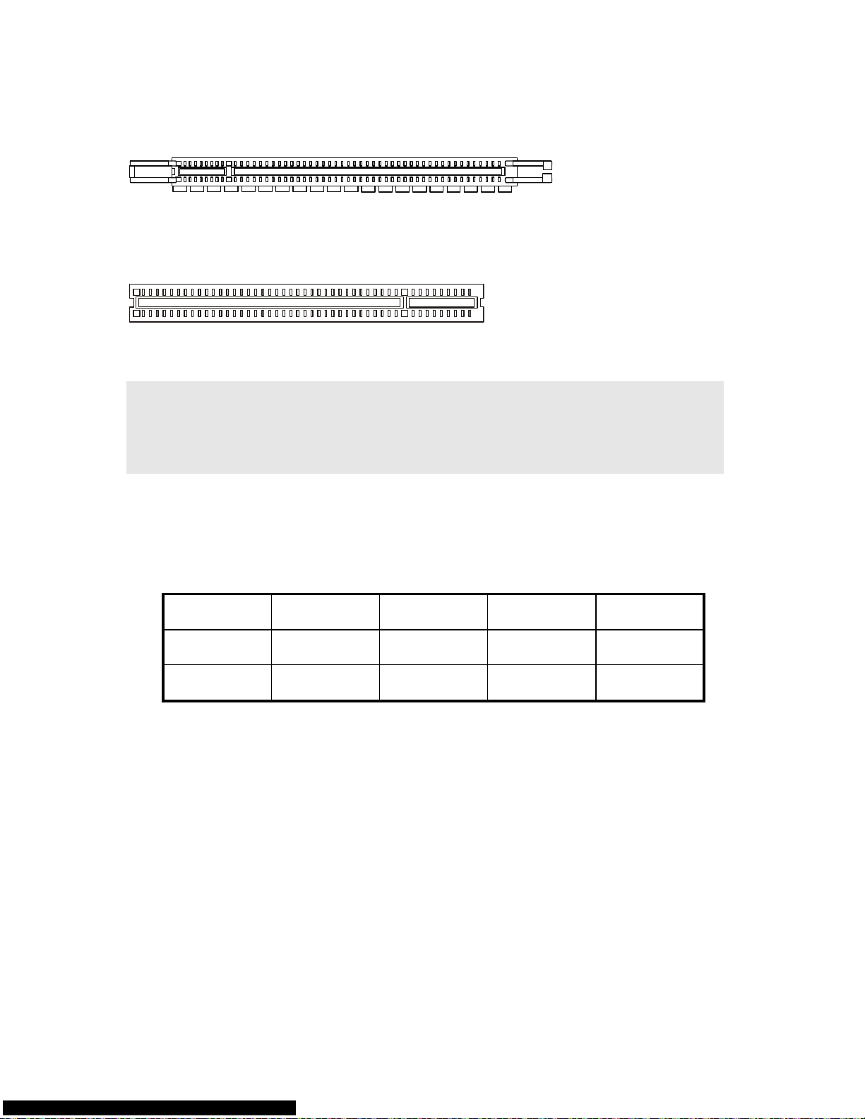
ATX 24-Pin Power Connector: ATX1
This connector allows you to connect an ATX 24-pin power supply.
To connect the ATX 24-pin power supply, make sure the plug of the
power supply is inserted in the proper orientation and the pins are
aligned. Then push down the power supply firmly into the
connector.
You may use the 20-pin ATX power supply as you like. If you like to
use the 20-pin ATX power supply, please plug your power supply
along with pin 1 & pin 13 (refer to the image at the right hand).
GND
GND
GND
PS-ON#
GND
+3.3V
-12V
+3.3V
+3.3V
+3.3V
+5V
+5V
+5V
+5V
+5V
Res
PWR OK
GND
GND
GND
GND
5VSB
+12V
+12V
ATX 12V Power Connector: JPW1
This 12V power connector is used to provide power to the CPU.
GND
GND
+12V
+12V
Important:
Make sure that all the connectors are connected to proper ATX power supplies to ensure
stable operation of the mainboard.
Power supply of 350 watts (and above) is highly recommended for system stability.
ATX 12V power connection should be greater than 18A.
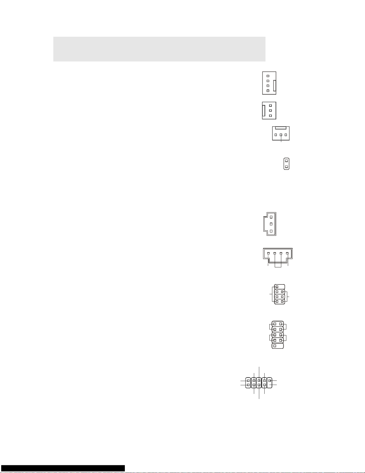
Floppy Disk Drive Connector: FDD1
This connector supports 360 KB, 720 KB, 1.2 MB, 1.44 MB
or 2.88 MB floppy disk drive.
IDE Connector: IDE1
This connector supports IDE hard disk drives, optical disk drives and other
IDE devices.
Important:
If you install two IDE devices on the same cable, you must configure the
drives to cable select mode or separately to master / slave mode by setting
jumpers. Refer to IDE device documentation supplied by the vendors for
jumper setting instructions.
Serial ATA Connector: SATA1 /SATA2/ SATA3/
SATA4
This connector is a high-speed Serial ATA interface port. Each connector
can connect to one Serial ATA device.
Page 13
7
Important:
Please do not fold the Serial ATA cable into 90-degree angle. Otherwise,
data loss may occur during transmission.
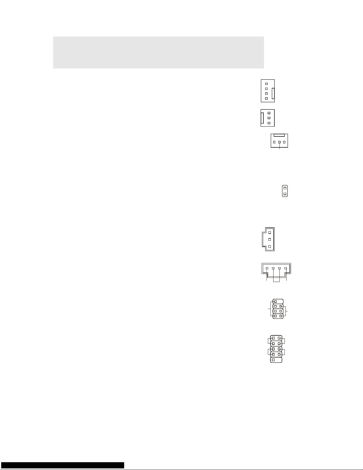
Fan Power Connectors: CPUFAN1,
SYSFAN1, SYSFAN2
The fan power connectors support system cooling fan with +12V.
When connecting the wire to the connectors, always note that the
red wire is the positive and should be connected to the +12V; the
black wire is Ground and should be connected to GND. If the
mainboard has a System Hardware Monitor chipset on-board, you
must use a specially designed fan with speed sensor to take
advantage of the CPU fan control.
GND
+12V
Sensor
Control
GND
+12V
Sensor
GND
+12V
Sensor
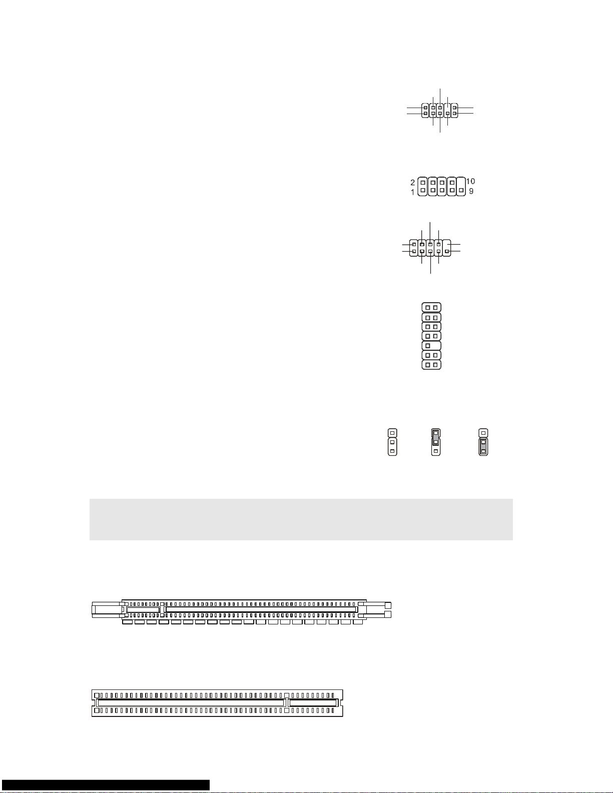
Chassis Intrusion Connector: JCI1
This connector connects to the chassis intrusion switch cable. If the
chassis is opened, the chassis intrusion mechanism will be
activated. The system will record this status and show a warning
message on the screen. To clear the warning, you must enter the
BIOS utility and clear the record.
CINTRU
GND
2
1
S/PDIF-Out Connector: JSPD1
This connector is used to connect S/PDIF (Sony & Philips Digital
Interconnect Format) interface for digital audio transmission.
GND
VCC
SPDIF
CD-In Connector: CD_IN1
This connector is provided for external audio input.
GND
L R
JFP2
Power
LED
Speaker
2
817
Front Panel Connectors: JFP1,
JFP2
These connectors are for electrical connection to the
front panel switches and LEDs. The JFP1 is compliant
with Intel® Front Panel I/O Connectivity Design Guide.
JFP1
HDD
LED
Reset
Switch
Power
Switch
Power
LED
1
9
10
2
+
+
+--
-
Front USB Connector: JUSB1,
JUSB2
This connector, compliant with Intel® I/O Connectivity
Design Guide, is ideal for connecting high-speed USB
interface peripherals such as USB HDD, digital cameras,
MP3 players, printers, modems and the like.
N.C.(10)
(2)VCC
USB1-
USB1+
GND
(1)VCC
USB0-
USB0+
GND
Key,no pin(9)
Page 14
8
Front Panel Audio Connector:
JAUD1
This connector allows you to connect the front panel
audio and is compliant with Intel® Front Panel I/O
Connectivity Design Guide.
(2)GND
VCC5
MIC2_JD
NC
(1)MIC_L
Line-out_R
Line-out_L(9)
Line_JD(10)
(2)GND
MIC_R
Front to Sense
SPI Debugging Connector: JSPI1
This connector is for internal debugging only.
Serial Port Connector: JCOM1
This connector is a 16550A high speed communication
port that sends/receives 16 bytes FIFOs. You can attach
a serial device to it.
Key,no pin
SIN
DTR
DSR
CTS
DCD
SOUT
GND
RTS
RI
(10)
(2)
(1) (9)
TPM Module connector:
JTPM1(Optional)
This connector connects to a TPM (Trusted Platform
Module) module. Please refer to the TPM security
platform manual for more details and usages.
KEY
GND
GND
14
3Vdual/ 3V_STB
2
VCC3
SIRQ
VCC5
LCLK
1
LRST#
LAD0
LAD1
LAD2
LAD3
LFRAME#
13
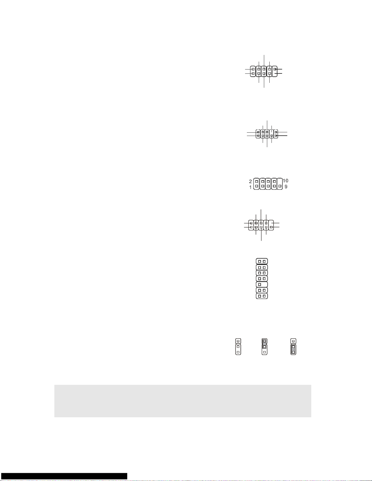
Clear CMOS Jumper: JBAT1
There is a CMOS RAM onboard that has a power supply
from an external battery to keep the data of system
configuration. With the CMOS RAM, the system can
automatically boot OS every time it is turned on. If you
want to clear the system configuration, set the jumper to
clear data.
Keep Data
Clear Data
2
2 2
3
3 3
1
1 1
Important:
You can clear CMOS by shorting 2-3 pin while the system is off. Then return to 1-2 pin
position. Avoid clearing the CMOS while the system is on; it will damage the mainboard.
PCI (Peripheral Component Interconnect) Express Slot
The PCI Express slot supports the PCI Express interface expansion card.
The PCI Express x 16 slot supports up to 4.0 GB/s transfer rate.
PCI (Peripheral Component Interconnect) Slot
Page 15
9
The PCI slot supports LAN card, SCSI card, USB card, and other add-on cards that
comply with PCI specifications.
Important:
When adding or removing expansion cards, make sure that you unplug the power supply
first. Meanwhile, read the documentation for the expansion card to configure any
necessary hardware or software settings for the expansion card, such as jumpers,
switches or BIOS configuration.
PCI Interrupt Request Routing
The IRQ, acronym of interrupt request line and pronounced I-R-Q, are hardware lines over
which devices can send interrupt signals to the microprocessor. The PCI IRQ pins are
typically connected to the PCI bus pins as follows:
Order1 Order2 Order3 Order4
PCI Slot1 INT A# INT B# INT C# INT D#
PCI Slot2 INT B# INT C# INT D# INT A#
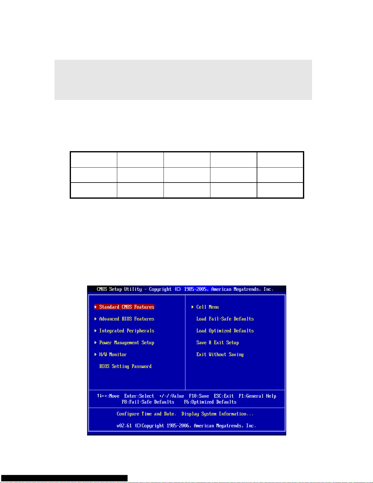
BIOS Setup
Power on the computer and the system will start POST (Power On Self Test) process. When
the message below appears on the screen, press <DEL> key to enter Setup.
Press DEL to enter SETUP
If the message disappears before you respond and you still wish to enter Setup, restart the
system by turning it OFF and On or pressing the RESET button. You may also restart the
system by simultaneously pressing <Ctrl>, <Alt>, and <Delete> keys.
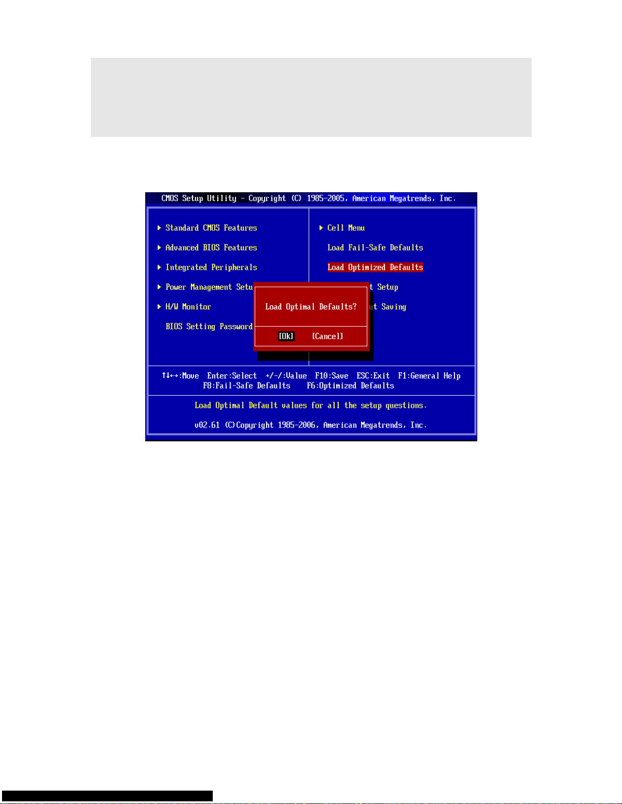
Main Page
Page 16
10
Standard CMOS Features
Use this menu for basic system configurations, such as time, date etc.
Advanced BIOS Features
Use this menu to setup the items of special enhanced features.
Integrated Peripherals
Use this menu to specify your settings for integrated peripherals.
Power Management Setup
Use this menu to specify your settings for power management.
H/W Monitor
This entry shows the status of your CPU, fan, warning overall system status.
BIOS Setting Password
Use this menu to set BIOS setting Password.
Cell Menu
Use this menu to specify your settings for frequency/voltage control.
Load Fail-Safe Defaults
Use this menu to load the BIOS default values that are factory settings for system
operations.
Load Optimized Defaults
Use this menu to load factory default settings into the BIOS for stable system performance
operations.
Save & Exit Setup
Save changes to CMOS and exit setup.
Exit Without Saving
Abandon all changes and exit setup.
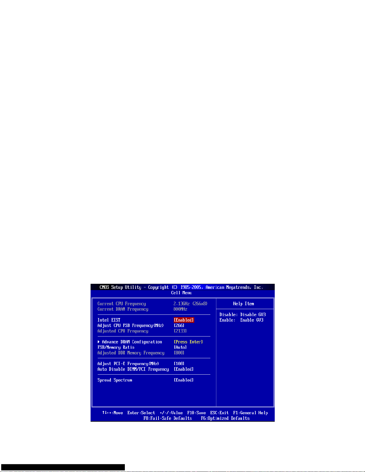
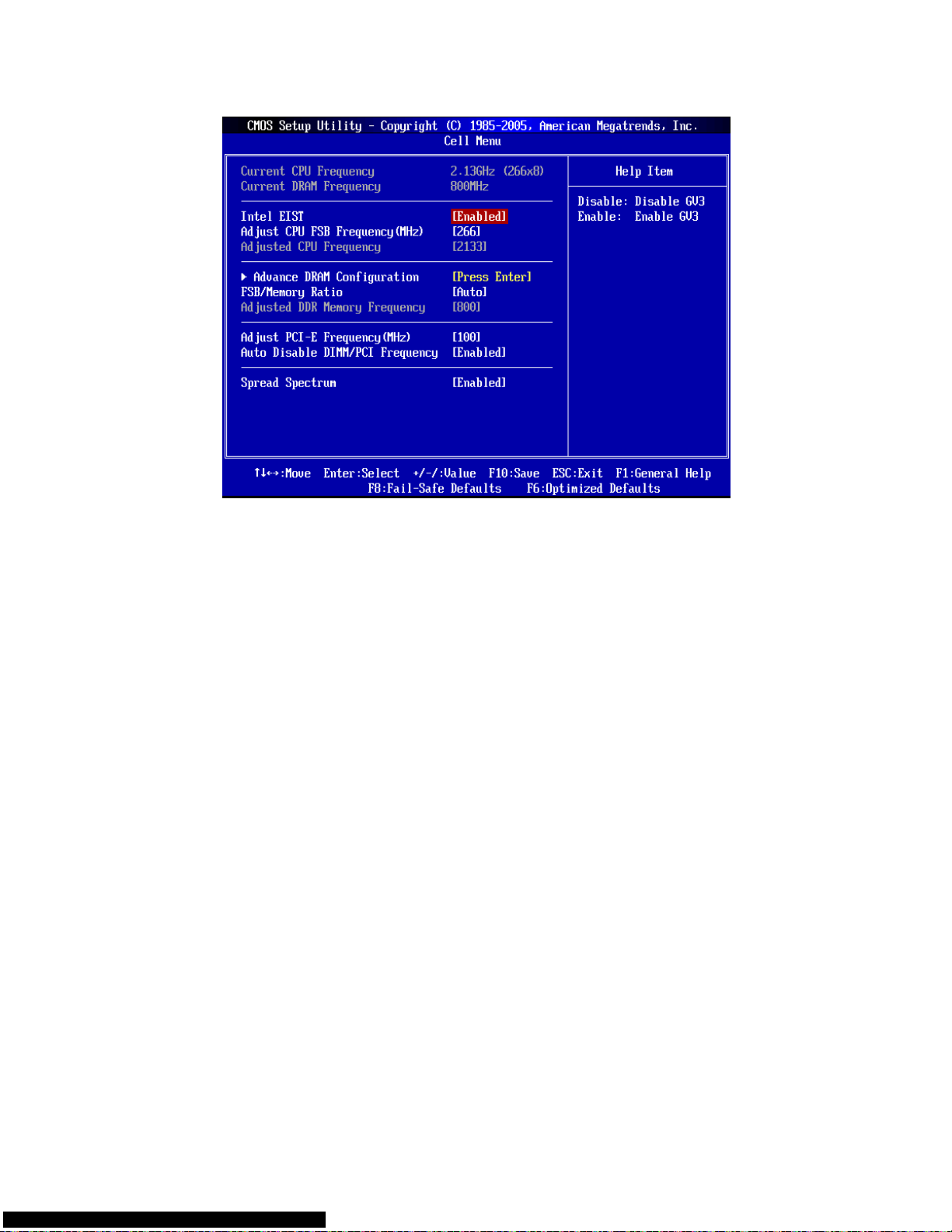
Cell Menu
Page 17

11
Current CPU Frequency
It shows the current frequency of CPU. Read-only.
Current DRAM Frequency
It shows the current frequency of Memory. Read-only.
Intel EIST
The Enhanced Intel SpeedStep® technology allows you to set the performance level of the
microprocessor whether the computer is running on battery or AC power. If you intent to
adjust the CPU Ratio, please set “Disabled” in this field. This field will appear after you
installed the CPU which support speedstep technology.
Adjust CPU FSB Frequency (MHz)
When Auto Detect CPU Frequency item set to [Disable], this item will allow you to manually
adjust the CPU FSB frequency.
Adjusted CPU Frequency
It shows the adjusted CPU frequency (FSB x Ratio). Read-only.
Advance DRAM Configuration > DRAM CAS# Latency
The field controls the CAS latency, which determines the timing delay before DRAM starts a
read command after receiving it. [2T] increases system performance while [2.5T] provides
more stable system performance. Setting to [By SPD] enables DRAM CAS# Latency
automatically to be determined by BIOS based on the configurations on the SPD (Serial
Presence Detect) EEPROM on the DRAM module.
FSB/Memory Ratio
When Auto Detect DRAM Frequency item set to [Disable], this item will allow you to
manually adjust the FSB/Ratio of the memory.
Adjusted DDR Memory Frequency
It shows the adjusted DDR Memory frequency. Read-only.
Adjust PCI-E Frequency (MHz)
This item allows you to select the PCI Express clock frequency (in MHz) and overclock by
adjusting the PCI Express clock to a higher frequency.
Auto Disable DIMM/PCI Frequency
When set to [Enabled], the system will remove (turn off) clocks from empty DIMM and PCI
slots to minimize the electromagnetic interference (EMI).
Spread Spectrum
When the motherboard’s clock generator pulses, the extreme values (spikes) of the pulses
create EMI (Electromagnetic Interference). The Spread Spectrum function reduces the EMI
generated by modulating the pulses so that the spikes of the pulses are reduced to flatter
curves. If you do not have any EMI problem, leave the setting at Disabled for optimal system
stability and performance. But if you are plagued by EMI, set to Enabled for EMI reduction.
Remember to disable Spread Spectrum if you are overclocking because even a slight jitter
can introduce a temporary boost in clock speed which may just cause your overclocked
processor to lock up.
Important:
If you do not have any EMI problem, leave the setting at [Disabled] for optimal system
stability and performance. But if you are plagued by EMI, select the value of Spread
Spectrum for EMI reduction.
Page 18
12
The greater the Spread Spectrum value is, the greater the EMI is reduced, and the system
will become less stable. For the most suitable Spread Spectrum value, please consult your
local EMI regulation.
Remember to disable Spread Spectrum if you are overclocking because even a slight jitter
can introduce a temporary boost in clock speed which may just cause your overclocked
processor to lock up.
Load Optimized Defaults
You can load the default values provided by the mainboard manufacturer for the stable
performance.
Page 19
13
INTRODUCTION
Félicitations, vous venez d’acquérir une carte mère des séries Micro-ATX G31M3 V2
(MS-7529 v1.x). Les G31M3 V2 séries sont basées sur les chipsets Intel® G31 et Intel®
ICH7 offrant un système très performant. La carte fonctionne avec le processeur LGA 775
de Intel® Core
TM
2 Duo/ Core
TM
2 Quad/ Pentium Dual-Core E2XXX et Celeron 4XXX/
Wolfdale séries, les séries G31M3 V2 sont très performantes et offrent une solution adaptée
tant aux professionnels qu’aux particuliers.
Schéma
Page 20

14
SPÉCIFICITÉS
Processeurs Supportés
l Supporte les processeurs de série Intel® Core
TM
2 Duo/ Core
TM
2 Quad/ Pentium
Dual-Core E2XXX et Celeron 4XXX/ Wolfdale dans le paquet LGA 775.
l Supporte un connecteur de 4 pins du ventilateur de CPU avec le Contrôleur de la vitesse
du ventilateur.
l Supporte TDP Max. 95W
(Pour plus d’informations sur le CPU, veuillez visiter :
http://global.msi.com.tw/index.php?func=cpuform)
FSB supporté
l 800/ 1066/ 1333 MHz
Chipset
l North Bridge: chipset Intel® G31
l South Bridge: chipset Intel® ICH7
Mémoire Supportée
l DDR2 667/ 800 SDRAM (4GB Max)
l 2 DDR2 DIMMs (240pin/ 1.8V)
(Pour plus d’informations sur les composants compatibles, veuillez visiter :
http://global.msi.com.tw/index.php?func=testreport)
LAN(Optionnel)
l Supporte Realtek® RTL8111C 10/100/1000 Mbps
l Supporte Realtek® RTL8101E 10/100 Mbps (optionnel)
l Compatible avec PCI 2.2
l Supporte ACPI Power Management
Audio
l Puce intégrée par Realtek® ALC888
l 8-canaux audio flexible avec détection de jack
l Compliant with Vista Premium
IDE
l 1 port IDE par ICH7
l Supporte le mode Ultra DMA 66/100
l Supporte les modes d’opération PIO, Bus Master
SATA
l 2 ports SATA II par ICH7
l Supporte 4 périphériques SATA II
l Supporte le stockage et un taux de transfert jusqu’à 3Gb/s
Disquette
l 1 port de disquette
l Supporte 1 FDD avec 360KB, 720KB, 1.2MB, 1.44MB et 2.88 MB.
Page 21

15
TPM (Optionnel)
l Supporte TPM
Connecteurs
l Panneau arrière
- 1 port souris PS/2
- 1 port clavier PS/2
- 1 port série (COM1)
- 1 port VGA
- 1 port parallèle supportant le mode SPP/EPP/ECP
- 4 ports USB 2.0
- 1 jack LAN RJ-45
- 3/6 jacks audio flexibles (optionnel)
l Connecteurs intégrés
- 2 connecteurs USB 2.0
- 1 connecteur CD-In
- 1 connecteur S/PDIF-Out
- 1 connecteur audio avant
- 1 connecteur port série
- 1 connecteur TPM (optionnel)
- 1 connecteur chassis intrusion switch
- 1 connecteur SPI Debugging
Slots
l 1 slot PCI Express x16
l 2 slots PCI
l Supporte l’interface bus PCI 3.3V / 5V
Dimension
l Micro-ATX (24.4cm X 19.3 cm)
Montage
l 6 trous de montage
Important:
Afin d’obtenir l’effet du son 8-canaux, il faut que le 7
ème
et 8
ème
canaux soient sortis du panal
avant (connecteur) si vous achetez une carte avec 3 jacks audio.
Page 22
16
Panneau Arrière
Le panneau arrière dispose les connecteurs suivants:
INSTALLATION MATÉRIELLE
Ce chapitre vous indique comment installer le CPU, les modules de mémoire, les cartes
d’extension et comment installer les cavaliers sur la carte. Il explique également comment
connecter périphériques tels que la souris, le clavier etc. Lors de l’installation du matériel,
veuillez suivre les instructions de montage pour éviter d’endommager quoi que ce soit.
Installation du LGA775 CPU et du refroidissement
Quand vous installerez votre CPU, assurez-vous que le CPU possède un système de
refroidissement pour prévenir les surchauffes. Si vous ne possédez pas de système de
refroidissement, contactez votre revendeur pour vous en procurer un et installez le avant
d’allumer l’ordinateur. N’oubliez pas d’utiliser des composants en silicium de transfert de
chaleur avant d’installer le refroidissement pour une meilleure dissipation de la chaleur.
Suivez les mesures suivantes pour installer correctement le système refroidissement et le
CPU, sinon, une mauvaise installation risque d’endommager votre CPU et la carte mère.
Introduction du LGA 775 CPU
La face de la galette à contacts du LGA
775 CPU
La surface du LGA 775 CPU
1. Le socket CPU possède un plastique de protection. Ne le
retirer qu’au moment d’installer le CPU.
2. Enlevez le chapeau de la charnière du levier.
3. On révèle les broches de la douille.
4. Ouvrez le levier de charge.
5. Lever le levier et ouvrir le plateau de chargement.
Page 23
17
6. Après avoir confirmé la direction du CPU pour joindre
correctement, déposez le CPU dans l'armature du logement
de douille. Faites attention au bord de sa base. Notez qu’on
aligne les coins assortis.
7. Inspectez visuellement si le CPU est posé bien dans la
douille. Si non, sortez verticalement le CPU pur et la
réinstallez.
8. Couvrez le plat de charge sur le paquet.
9. Abaisser le levier sur le plateau de chargement, puis
sécuriser l’ensemble avec le mécanisme de rétention.
10. Aligner les trous de la carte avec ventilateur. Installer le
ventilateur dans les trous de la carte mère.
11. Appuyez sur le crochets pour attacher le ventilatuer. Puis
effectuer une rotation des systèmes de rétention (voir
ventilateur pour le sens de rotation).
12. Retourner la carte mère pour s’assurer que le ventilateur est
correctement installé.
Important:
Lisez les status du CPU dans le BIOS.
Toujours protégez les pins de socket du CPU avec le platique de tout domage quand le
CPU n’est pas installé.
Les photos de carte sont montrées ici pour une démonstration de l’installation du ventilateur
des CPU de Socket AM2 seulement. L’apparence de votre carte peut changer selon le
model que vous achetez.
Installation des modules de mémoire
1. Le module de mémoire ne possède qu’une encoche en son centre. Ainsi il n’est
possible de monter le module que dans un seul sens.
2. Insérez verticalement le module de mémoire dans le slot DIMM. Puis poussez le
là-dedans jusqu’à ce que le doigt d’or sur le module de mémoire est inséré
profondément dans le slot DIMM. Vous ne pouvez presque pas voir le doigt d’or si le
module de mémoire est correctement inséré dans le slot DIMM.
3. Le clip en plastique situé de chaque côté du module va se fermer automatiquement.
Volt
Notch
Page 24
18
Important:
Les modules de mémoire DDR2 ne sont pas interchangeables par DDR et vice versa. Vous
devez installer toujours les modules de mémoire DDR2 dans les slots DDR2 DIMM.
Pour lancer avec succès votre ordinateur, insérez tout d’abord les modules de mémoire
dans le DIMM1.
Connecteur d’alimentation ATX 24-Pin:
ATX1
Ce connecteur vous permet de connecter l’alimentation ATX
20-broche. Pour cela assurez-vous que le connecteur est bien
positionné dans le bon sens et que les goupilles sont alignées.
Abaissez alors l'alimentation d'énergie dans le connecteur.
Vous pouvez utiliser ce connecteur d’alimentation de 20-pin ATX
comme vous voulez. Si vous préférez de l’utilier, veuillez connecter
ce connecteur d’alimentation avec le pin 1 et pin 13 (référez à
l’image à droite).
GND
GND
GND
PS-ON#
GND
+3.3V
-12V
+3.3V
+3.3V
+3.3V
+5V
+5V
+5V
+5V
+5V
Res
PWR OK
GND
GND
GND
GND
5VSB
+12V
+12V
Connecteur d’alimentation ATX 12V:
JPW1
Le connecteur d’alimentation 12V est utilisé pour alimenter le CPU.
GND
GND
+12V
+12V
Important:
Assurez-vous que tous les connecteurs sont reliés à l’alimentation ATX pour assurer une
stabilité de la carte mère.
L’alimentation 350 watts (ou supérieur) est recommandée pour la stabilité du système.
Le connecteur d’alimentation de ATX 12V doit être plus de 18A.
Connecteur Floppy Disk Drive: FDD1
Ce connecteur supporte les formats 360KB, 720KB, 1.2MB,
1.44MB ou 2.88MB.
Connecteur IDE: IDE1
Ce connecteur supporte les disques durs IDE, les lecteurs du disque
optique et d’autres dispositifs IDE.
Important:
Si vous installez deux IDE devices sur un même câble, vous devez
configurer le second dans le mode cable select ou dans le mode master /
slave séparément en configurant le cavalier. Référez-vous aux
documentations d’IDE devices fournis par les vendeurs pour les
instructions d’arrangement de cavalier.
Connecteur série ATA: SATA1 /SATA2/ SATA3/
SATA4
Ce connecteur est un port d’interface de haute vitesse Série ATA. Chaque
connecteur peut se connecter à un dispositif Série ATA.
Page 25
19
Important:
Veuillez ne pas tordre le câble Série ATA à 90 degrés. Cela pourrait
l’endommager et entraîner la perte de données lors des phases de
transfert de celles-ci.
Connecteurs d’alimentation du
ventilateur: CPUFAN1, SYSFAN1,
SYSFAN2
Les connecteurs d’alimentation du système de refroidissement
supportent un système de refroidissement de +12V. Lors de la
connexion du câble, assurez-vous que le fil rouge soit connecté au
+12V et le fil noir connecté au “GND“. Si la carte mère possède un
système de gestion intégré, vous devez utiliser un ventilateur ayant
ces caractéristiques si vous voulez contrôler le ventilateur du CPU.
GND
+12V
Sensor
Control
GND
+12V
Sensor
GND
+12V
Sensor
Connecteur de Châssis Intrusion: JCI1
Ce connecteur est connecté à un cable chassis intrusion switch. Si
le châssis est ouvert, le switch en informera le système, qui
enregistrera ce statut et affichera un écran d’alerte. Pour effacer ce
message d’alerte, vous devez entrer dans le BIOS et désactiver
l’alerte.
CINTRU
GND
2
1
Connecteur S/PDIF-Out: JSPD1
Ce connecteur est utilisé pour contacter l’interface S/PDIF (Sony &
Philips Digital Interconnect Format) à la transmission numérique
audio.
GND
VCC
SPDIF
Connecteur CD-In: CD_IN1
Ce connecteur est fournit pour un audio externe d’entrer.
GND
L R
JFP2
Power
LED
Speaker
2
817
Connecteurs Panneau avant: JFP1,
JFP2
Ces connecteurs sont pour des connections eletriques
aux commutateurs et LEDs en panneau avant. Le JFP1
est compatible avec Intel® Front Panel I/O Connectivity
Design Guide.
JFP1
HDD
LED
Reset
Switch
Power
Switch
Power
LED
1
9
10
2
+
+
+--
-
Page 26
20
Connecteur USB avant: JUSB1,
JUSB2
Ce connecteur, compatible avec Intel® I/O Connectivity
Design Guide, est idéal pour connecter les USB
périphérique d’interface de haute vitesse tel que USB
HDD, caméras numériques, lecteur MP3, imprimants,
modems et etc..
N.C.(10)
(2)VCC
USB1-
USB1+
GND
(1)VCC
USB0-
USB0+
GND
Key,no pin(9)
Connecteur Audio Panneau avant:
JAUD1
Ce connecteur vous permet de connecter un audio en
panneau avant. Il est compatible avec Intel® Front Panel
I/O Connectivity Design Guide.
(2)GND
VCC5
MIC2_JD
NC
(1)MIC_L
Line-out_R
Line-out_L(9)
Line_JD(10)
(2)GND
MIC_R
Front to Sense
Connecteur de débogage SPI:
JSPI1
Ce connecteur est pour le débogage intégré uniquement.
Conncteur du port de série: JCOM1
Ce connecteur est un port de communication haute
vitesse 16550A qui envoie/reçoit 16 bytes FIFOs. Vous
pouvez y attacher une série de périphériques.
Key,no pin
SIN
DTR
DSR
CTS
DCD
SOUT
GND
RTS
RI
(10)
(2)
(1) (9)
Connecteur de TPM Module:
JTPM1(Optionnel)
Ce connecteur est relié à un TPM (Trusted Platform
Module) module (optionnel). Veuillez vous référer au
manuel de TPM plat-forme de sécurité pour plus de
détails et d’utilisations.
KEY
GND
GND
14
3Vdual/ 3V_STB
2
VCC3
SIRQ
VCC5
LCLK
1
LRST#
LAD0
LAD1
LAD2
LAD3
LFRAME#
13
Cavalier Effacer COMS: JBAT1
Le CMOS RAM intégré reçoit une alimentation d’une
batterie externe qui permet de garder les données de
configuration du système. Avec le CMOS RAM, le
système peut automatiquement démarrer avec les
paramètres personnalisés du BIOS à chaque fois que le
PC est allumé. Si vous voulez effacer la configuration du
système, utilisez le JBAT1 pour effacer les données.
Keep Data
Clear Data
2
2 2
3
3 3
1
1 1
Important:
Vous pouvez effacer le CMOS en positionnant le cavalier sur les broches 2-3 lorsque le
PC n’est pas allumé. Puis il faut remettre le cavalier en position 1-2. Ne surtout pas
effacer le CMOS lorsque le PC est allumé, cela endommagera la carte mère.
Page 27
21
Slot PCI (Peripheral Component Interconnect) Express
Le slot PCI Express supporte la carte d’expansion d’interface PCI Express.
Le slot PCI Express x 16 supporte un taux de transfert jusqu’à 4.0 GB/s.
Slot PCI (Peripheral Component Interconnect)
Le slot PCI support la carte LAN, la carte SCSI, la carte USB, et d’autres cartes ajoutées
qui sont compatibles avec les spécifications de PCI.
Important:
Quand vous ajoutez ou enlevez les cartes d’expansion, assurez-vous de débrocher
d’abords l’alimentation. En même temps, lisez les documentations afin de configurer tous
les matériel et logiciel nécessaires pour la carte d’expansion, tel que les cavaliers,
switches ou la configurations du BIOS.
PCI Interrupt Request Routing
IRQ, est l’abréviation de “interrupt request line”. Les IRQ sont des signaux émis par des
matériels. Les PCI IRQ sont connectés généralement au broches PCI bus INT A# ~ INT D#
comme suivant:
Order1 Order2 Order3 Order4
PCI Slot1 INT A# INT B# INT C# INT D#
PCI Slot2 INT B# INT C# INT D# INT A#
BIOS Setup
Lorsque le PC démarre, le processus de POST (Power On Self Test) se met en route.
Quand le message ci-dessous apparaît à l’écran, appuyer sur <DEL> pour accéder au
Setup.
Appuyer sur DEL pour accéder au SETUP
Si le message disparaît avant que n’ayez appuyé sur la touche, redémarrez le PC avec
l’aide du bouton RESET. Vous pouvez aussi redémarrer en utilisant la combinaison des
touches <Ctrl>, <Alt>, et <Delete>.
Page 28

22
Page Principale
Standard CMOS Features
Cette fonction permet le paramétrage des éléments standard du BIOS tels que l’heure, etc
Advanced BIOS Features
Cette fonction permet de paramétrer des éléments avancés du BIOS.
Integrated Peripherals
Utilisez ce menu pour paramétrer les périphériques intégrés.
Power Management Setup
Utilisez ce menu pour appliquer vos choix en ce qui concerne l’alimentation.
H/W Monitor
Permet de voir les statuts du CPU, du ventilateur, et de l’alarme du système.
BIOS Setting Password
Utilisez ce menu pour entrer un mot de passe pour le BIOS.
Cell Menu
Utilisez ce menu pour spécifier votre configuration pour le contrôleur de fréquence/ voltage
de CPU/AGP et overclocking.
Load Fail-Safe Defaults
Utilisez ce menu pour charger les valeurs par défaut configures par votre vendeur pour une
performance stable du système.
Load Optimized Defaults
Charge les paramètres optimums du BIOS par défauts sans affecter la stabilité du système.
Save & Exit Setup
Les modifications sont enregistrées dans le CMOS avant la sortie du Setup.
Exit Without Saving
Les modifications sont abandonnées avant la sortie du Setup.
Page 29
23
Cell Menu
Current CPU Frequency
Cette icône montre la fréquence actuelle du CPU. Lecture uniquement.
Current DRAM Frequency
Cette icône montre la fréquence actuelle de la Mémoire. Lecture uniquement.
Intel EIST
La technologie Enhanced Intel SpeedStep® vous permet de configurer le niveau de
performance du microprocesseur si l’ordinateur fonctionne en batterie ou en l’adapteur
d’alimentation. Ce domaine apparaîtra après que vous installiez le CPU qui supporte la
technologie de speedstep.
Adjust CPU FSB Frequency(MHz)
Quand l’article Auto Detect CPU Frequency est mis en [Disable], il vous permet d’ajuster la
fréquence de FSB du CPU manuellement.
Adjusted CPU Frequency
Il montre la fréquence du CPU ajusté (FSB x Ratio). Lecture uniquement.
Advance DRAM Configuration > DRAM CAS# Latency
Ce domaine contrôle la latence CAS, qui détermine le retard de timing avant que le DRAM
commence un ordre de lecture après l’avoir reçu.. [2T] augmente la performance du
système et [2.5T] fournit une performance plus stable du système. Mettre en [By SPD] rend
DRAM CAS# Latence déterminée automatiquement par BIOS bas é sur les configurations
en SPD (Serial Presence Detect) EEPROM sur le module de DRAM.
FSB/Memory Ratio
Quand l’article Auto Detect DRAM Frequency est en [Disable], cet article permettra d’ajuster
manuellement la fréquence de FSB/Ratio de la mémoire.
Adjusted DDR Memory Frequency
Il montre la fréquence ajustée de DRAM. Lecture uniquement.
Page 30

24
Adjust PCI-E Frequency(MHz)
Cet article vous permet de sélectionner la fréquence de PCI Expres (en MHz) et de
l’’overclocker en ajustant l’horloge de PCI Express à une fréquence plus haut.
Auto Disable DIMM/PCI Frequency
Cet article est utilisé pour désactiver automatiquement les slots de PCI. Lorsqu’il est activé,
le système éteindra les horloges des fentes vides de PCI pour réduire au minimum
l’interface électromagnétique (EMI).
Spread Spectrum
Lorque le clock generator de la carte mère fonctionne, les valeurs extrêmes (spikes) créent
des interférences électromagnétiques (EMI - Electromagnetic Interference). La fonction
Spread Spectrum réduit ces interférences en réglant les impultions. Si vous n’avez pas de
problème d’EMI, laissez l’option sur Disabled, ceci vous permet d’avoir une stabilité du
système et des performances optimales. Dans le cas contraire, choisissez Enabled pour
réduire les interférences. N’oubliez pas de désactiver cette fonction si vous voulez faire de
l’ overclocking, parce que la moindre modification peut entraîner une accélération temporaire
d’horloge et ainsi votre processeur overclocké se verrouillera.
Important:
Si vous n’avez pas de problème d’EMI, laissez l’option sur [Disabled], ceci vous permet
d’avoir une stabilité du système et des performances optimales. Dans le cas contraire,
choisissez Spread Spectrum pour réduire les EMI.
Plus la valeur Spread Spectrum est importante, plus les EMI sont réduites, et le système
devient moins stable. Pour la valeur Spread Spectrum la plus convenable, veuillez
consultez le règlement EMI local.
N’oubliez pas de désactiver la fonction Spread Spectrum si vous êtes en train d’overclocker
parce que même un battement léger peut causer un accroissement temporaire de la vitesse
de l’horloge qui verrouillera votre processeur overclocké.
Load Optimized Defaults
Vous pouvez charger les valeurs de défaut fournites par la manufacture de carte pour une
performance stable.
Page 31

25
EINLEITUNG
Danke, dass Sie das G31M3 V2 Series (MS-7529 v1.x) Micro-ATX Mainboard gewählt
haben. Das G31M3 V2 Series Series basiert auf dem Intel® G31 & Intel® ICH7 Chipsatz und
ermöglicht so ein optimales und effizientes System. Entworfen, um den hochentwickelten
Intel® Core
TM
2 Duo/ Core
TM
2 Quad/ Pentium Dual-Core E2XXX und Celeron 4XXX/
Wolfdale Series LGA 775 Prozessoren, stellt das G31M3 V2 Series die ideale Lösung zum
Aufbau eines professionellen Hochleistungsdesktopsystems dar.
Layout
Page 32

26
SPEZIFIKATIONEN
Prozessoren
l Unterstützt Intel® Core
TM
2 Duo/ Pentium Dual-Core E2XXX und Celeron 4XXX/ Wolfdale
Series Prozessoren für Sockel LGA 775.
l Unterstützt CPU Lüftersteuerung über eine 4-polige Stiftleiste
l Unterstützt TDP max. 95W
(Weitere CPU Informationen finden Sie unter:
http://global.msi.com.tw/index.php?func=cpuform)
FSB(Front-Side-Bus)
l 800/ 1066/ 1333 MHz
Chipsatz
l North-Bridge: Intel® G31 Chipsatz
l South-Bridge: Intel® ICH7 Chipsatz
Speicher
l DDR2 667/ 800 SDRAM (max. 4GB)
l 2 DDR2 DIMMs (240Pin/ 1.8V)
(Weitere Informationen zu kompatiblen Speichermodulen finden Sie unter:
http://global.msi.com.tw/index.php?func=testreport)
LAN(Optional)
l Unterstützt Realtek® RTL8111C 10/100/1000 Mbps
l Unterstützt Realtek® RTL8101E 10/100 Mbps (optional)
l Erfüllt die Anforderungen gemäß dem Standard PCI 2.2
l Unterstützt ACPI Stromsparfunktionalität
Audio
l Onboard Soundchip Realtek® ALC888
l 8-Kanal Audio-Ausgang mit „Jack sensing“
l Zertifiziert für das Microsoft Vista Premium Betriebssystem
IDE
l 1 IDE Port über ICH7
l Unterstützt die Betriebmodi Ultra DMA 66/100 mode
l Unterstützt die Betriebmodi PIO, Bus Mastering
SATA
l 2 SATA II Ports über ICH7
l Unterstützt 4 SATA II Geräte
l Unterstützt Datenübertragungsraten von bis zu 3Gb/s
Diskette
l 1 Disketten Anschluss
l Unterstützt 1 Diskettenlaufwerk mit 360 KB, 720 KB, 1.2 MB, 1.44 MB und 2.88 MB.
Page 33

27
TPM (Optional)
l Unterstützt TPM
Anschlüsse
l Hintere Ein-/ und Ausgänge
- 1 PS/2 Mausanschluss
- 1 PS/2 Tastaturanschluss
- 1 Serielle Schnittstelle (COM1)
- 1 VGA Anschluss
- 1 Parallele Schnittstelle unterstützt die Betriebsmodi SPP/EPP/ECP
- 4 USB 2.0 Anschlüsse
- 1 RJ-45 LAN Buchse
- 3/6 Audiobuchsen (optional)
l On-Board Stiftleiste/ Anschlüsse
- 2 USB 2.0 Stiftleisten
- 1 CD Stiftleiste für Audio Eingang
- 1 S/PDIF-Ausgang Stiftleiste
- 1 Audio Stiftleiste für Gehäuse Audio Ein-/ Ausgänge
- 1 Serielle Stiftleiste
- 1 TPM Stiftleiste (optional)
- 1 Gehäusekontaktschalter
- 1 SPI Behegung Anschluss
Schnittstellen
l 1 PCI Express x16 Schnittstelle
l 2 PCI Schnittstelle
l Unterstützt 3.3V/ 5V PCI Bus Interface
Form Faktor
l Micro-ATX (24.4cm X 19.3 cm)
Mountage
l 6 Montagebohrungen
Wichtig:
Für der 8-Kanal Geräuscheffekt, wenn Sie das mainboard mit 3 Audiobuchsen kaufen,
müssen die 7. und 8. Kanal von der Frontpanel (Stiftleiste) abgefragt.
Page 34

28
Hinteres Anschlusspanel
Das hintere Anschlusspanel verfügt über folgende Anschlüsse:
HARDWARE SETUP
Dieses Kapitel informiert Sie darüber, wie Sie die CPU, CPU Kühler und Speichermodule,
Erweiterungskarten einbauen, des weiteren darüber,wie die Steckbrücken auf dem
Mainboard gesetzt werden. Zudem bietet es Hinweise darauf, wie Sie Peripheriegeräte
anschließen, wie z.B. Maus, Tastatur, usw. Handhaben Sie die Komponenten während des
Einbaus vorsichtig und halten Sie sich an die vorgegebene Vorgehensweise beim Einbau.
CPU & Kühler Einbau für Sockel LGA775
Wenn Sie die CPU einbauen, stellen Sie bitte sicher, dass Sie auf der CPU einen Kühler
anbringen, um Überhitzung zu vermeiden. Vergessen Sie nicht, etwas
Siliziumwärmeleitpaste auf die CPU aufzutragen, bevor Sie den Prozessorkühler
installieren, um eine Ableitung der Hitze zu erzielen.
Folgen Sie den Schritten unten, um die CPU und den Kühler ordnungsgemäß zu installieren.
Ein fehlerhafter Einbau führt zu Schäden an der CPU und dem Mainboard.
Erklärung zur LGA 775 CPU
Die Pin-Seite der LGA 775 CPU
Die Obserseite der LGA775 CPU
1. Der CPU-Sockel besitzt zum Schutz eine Plastikabdeckung.
Lassen Sie vor der Installation diese Schutzkappe auf dem
Sockel um Schäden zu vermeiden.
2. Entfernen Sie zuerst die Schutzkappe wie abgebildet in
Pfeilrichtung.
3. Sie sehen jetzt die Pins des Sockels.
4. Öffnen Sie den Sockelverschlusshebel.
Page 35

29
5. Klappen Sie den Hebel ganz auf und öffnen Sie die
Metallverschlussklappe.
6. Vergewissern Sie sich anhand der Justiermarkierungen und
dem gelben Dreieck, daß die CPU in der korrekten Position
ist. Setzen Sie anschließend die CPU in den Sockel.
7. Begutachten Sie, ob die CPU richtig im Sockel sitzt. Falls
nicht, ziehen Sie die CPU durch eine rein vertikale
Bewegung wieder heraus. Versuchen Sie es erneut.
8. Schließen Sie die Abdeckung des Sockels.
9. Drücken Sie den Verschlusshebel mit leichtem Druck nach
unten und arretieren Sie den Hebel unter dem
Rückhaltehaken des CPU-Sockels.
10. Führen Sie den CPU-Kühler über den CPU-Sockel und
positionieren Sie die Arretierungsstifte des Kühlers über die
dafür vorgesehenen Löcher des Mainboards. Drücken Sie
den Kühler nach unten bis die Stifte in den Löchern
eingerastet sind.
11. Drehen Sie das Mainboard um und vergewissern Sie sich,
dass das der Kühler korrekt installiert ist
Wichtig:
Prüfen Sie die Status der CPU im BIOS.
Wenn keine CPU installiert ist, schützen Sie immer den CPU-Sockel durch die
Plastikabdeckung.
Die Mainboard Fotos, die in diesem Abschnitt gezeigt werden, sind für Demonstration der
CPU/ Kühler Installation. Das Aussehen Ihres mainboard kann abhangig von dem Modell
schwanken, das Sie kaufen. Das Aussehen Ihres Mainboards kann abhängig von dem
Modell schwanken, welches Sie erworben haben.
Vorgehensweise beim Einbau von Speicher Modulen
1. Die Speichermodule haben nur eine Kerbe in der Mitte des Moduls. Sie passen nur in
einer Richtung in den Sockel.
2. Setzen Sie den DIMM- Speicherbaustein senkrecht in den DIMM- Sockel, dann
drücken Sie ihn hinein, bis die goldenen Kontakte tief im Sockel sitzen. Die
Plastikklammern an den Seiten des DIMM- Sockels schließen sich automatisch.
3. Überprüfen Sie manuell, wenn die Speichermodule durch den DIMM- Sockel
eingerastet worden
Volt
Notch
Page 36

30
Wichtig:
DDR2 und DDR können nicht untereinander getauscht werden und der Standard DDR2 ist
nicht rückwärtskompatibel, installieren Sie DDR2 Speichermodule stets in DDR2 DIMM
Slots und DDR Speichermodule stets in DDR DIMM Slots.
Um einen sicheren Systemstart zu gewährleisten, bestücken Sie immer DIMM 1 zuerst.
ATX 24-Pin Stromanschluss: ATX1
Hier können Sie ein ATX 24-Pin Netzteil anschließen. Wenn Sie die
Verbindung herstellen, stellen Sie sicher, dass der Stecker in der
korrekten Ausrichtung eingesteckt wird und die Pins ausgerichtet
sind. Drücken Sie dann den Netzteilstecker fest in den
Steckersockel.
Sie können auch ein 20-Pin ATX Netzteil verwenden, wenn Sie
möchten. Wenn Sie ein 20-Pin ATX Netzteil einsetzen möchten,
stecken Sie bitte Ihr Netzteil beginnend bei den Pins 1 und 13 ein
(Bitte informieren Sie sich auf rechte Seite von Bild).
GND
GND
GND
PS-ON#
GND
+3.3V
-12V
+3.3V
+3.3V
+3.3V
+5V
+5V
+5V
+5V
+5V
Res
PWR OK
GND
GND
GND
GND
5VSB
+12V
+12V
ATX 12V Stromanschluss: JPW1
Dieser 12V Stromanschluss wird verwendet, um die CPU mit Strom
zu versorgen.
GND
GND
+12V
+12V
Wichtig:
Stellen Sie die Verbindung aller drei Anschlüsse mit einem angemessenem ATX Netzteil
sicher, um den stabilen Betrieb des Mainboards sicher zu stellen.
Netzteile mit 350 Watt (und mehr) werden aus Gründen der Systemstabilität dringend
empfohlen.
Die ATX 12V Stromversorgung sollte mit mehr als 18A erfolgen.
Anschluss des Diskettenlaufwerks:
FDD1
Der Anschluss unterstützt ein Diskettenlaufwerke mit
360KB, 720KB, 1.2MB, 1.44MB oder 2.88MB Kapazität.
IDE Anschluss: IDE1
Anschluss können bis zu IDE Festplatten, optical Diskettenlaufwerke und
andere Geräte angeschlossen werden.
Wichtig:
Verbinden Sie zwei Laufwerke über ein Kabel, müssen Sie das zweite
Laufwerk im Slave-Modus konfigurieren, indem Sie entsprechend den
Jumper setzen. Entnehmen Sie bitte die Anweisungen zum Setzen des
Jumpers der Dokumentation der Festplatte, die der Festplattenhersteller
zur Verfügung stellt.
Page 37

31
Serial ATA Anschlüsse: SATA1 /SATA2/ SATA3/
SATA4
Der Anschluss ist ein hoch-Geschwindigkeit Schnittstelle der Serial ATA .
An jeden connector can Anschluss kann eine Serial ATA Anschluss
angeschlossen werden.
Wichtig:
Bitte falten Sie das Serial ATA Kabel nicht in einem Winkel von 90 Grad. da
dies zu Datenverlusten während der Datenübertragung führt.
Stromanschlüsse für Lüfter: CPUFAN1,
SYSFAN1, SYSFAN2
Die Netzteillüfter Anschlüsse unterstützen aktive Systemlüfter mit
+12V. Wenn Sie den Stecker mit dem Anschluss verbinden, sollten
Sie immer darauf achten, dass der rote Draht der positive Pol ist
und mit +12V verbunden werden sollte, der schwarze Draht ist der
Erdkontakt und sollte mit GND verbunden werden. Besitzt Ihr
Mainboard einen Chipsatz zur Überwachung der Systemhardware
und Steuerung der Lüfter, dann brauchen Sie einen speziellen
Lüfter mit Tacho, um diese Funktion zu nutzen.
GND
+12V
Sensor
Control
GND
+12V
Sensor
GND
+12V
Sensor
Gehäusekontaktschalter: JCI1
Dieser Anschluss wird mit einem Kontaktschalter verbunden. Wird
das Gehäuse geöffnet, wird der Schalter geschlossen und das
System zeichnet dies auf und gibt auf dem Bildschirm eine
Warnung aus. Um die Warnmeldung zu löschen, muss das BIOS
aufgerufen und die Aufzeichnung gelöscht werden.
CINTRU
GND
2
1
S/PDIF- Ausgang: JSPD1
Die SPDIF (Sony & Philips Digital Interconnect Format)
Schnittstelle wird für die Übertragung digitaler Audiodaten
verwendet.
GND
VCC
SPDIF
CD-Eingang: CD_IN1
Dieser Anschluss wird für externen Audioeingang zur Verfügung
gestellt.
GND
L R
JFP2
Power
LED
Speaker
2
817
Frontpanel Anschlüsse: JFP1,
JFP2
Die Anschlüsse für das Frontpanel dienen zum
Anschluss der Schalter und LEDs des Frontpaneels.
JFP1 erfüllt die Anforderungen des Intel® Front Panel I/O
Connectivity Design Guide.
JFP1
HDD
LED
Reset
Switch
Power
Switch
Power
LED
1
9
10
2
+
+
+--
-
Page 38

32
USB Frontanschluss: JUSB1,
JUSB2
Der Anschluss entspricht den Richtlinien des Intel® Front
Panel I/O Connectivity Design Guide, und ist bestens
geeignet, Hochgeschwindigkeits- USB- Peripheriegeräte
anzuschließen, wie z.B. USB Festplattenlaufwerke,
Digitalkameras, MP3-Player, Drucker, Modems und
ähnliches.
N.C.(10)
(2)VCC
USB1-
USB1+
GND
(1)VCC
USB0-
USB0+
GND
Key,no pin(9)
Audioanschluss des Frontpanels:
JAUD1
Der Audio Frontanschluss ermöglicht den Anschluss von
Audioein- und -ausgängen eines Frontpanels. Der
Anschluss entspricht den Richtlinien des Intel
®
Front
Panel I/O Connectivity Design Guide.
(2)GND
VCC5
MIC2_JD
NC
(1)MIC_L
Line-out_R
Line-out_L(9)
Line_JD(10)
(2)GND
MIC_R
Front to Sense
SPI Behegung Anschluss: JSPI1
Der Anschluss nur für innen.Behegung.
Seriieller Anschluss: JCOM1
Es handelt sich um eine 16550A
Hochgeschwindigkeitskommunikationsschnittstelle, die
16 Bytes FIFOs senden/empfängt. Hier lässt sich eine
Serielle Maus oder andere Serielle Geräte direkt
anschließen.
Key,no pin
SIN
DTR
DSR
CTS
DCD
SOUT
GND
RTS
RI
(10)
(2)
(1) (9)
TPM Module Anschluss:
JTPM1(Optional)
Dieser Anschluss wird für das optionale TPM Modul
(Trusted Platform Module) verwendet. Weitere
Informationen finden Sie im "TPM Sicherheitsplattform
Handbuch"
KEY
GND
GND
14
3Vdual/ 3V_STB
2
VCC3
SIRQ
VCC5
LCLK
1
LRST#
LAD0
LAD1
LAD2
LAD3
LFRAME#
13
Steckbrücke zur CMOS- Löschung:
JBAT1
Der Onboard CMOS Speicher (BIOS), enthält
Grundinformationen sowie erweite Eistellungen des
Mainboards. Der CMOS Speicher wird über eine Betterie
mit Strom versotgt, damit die Daten nach Abschalten des
PC-systems erhalten bleiben. Wieterhin sind
Informationen für den Start des Systems in dem Speicher
hinterlegt. Sollten Sie Fehlermeldungen während des
Startvorganges erhalten, kann ein Zurücksetzen des
CMOS Speichers in den ursprünglichen Werkszustand
helfen. Drücken Sie dazu leicht den Schalter.
Keep Data
Clear Data
2
2 2
3
3 3
1
1 1
Page 39

33
Wichtig:
Sie können den CMOS löschen, indem Sie die Pins 2-3 verbinden, während das System
ausgeschaltet ist. Kehren Sie danach zur Pinposition 1-2 zurück. Löschen Sie den CMOS
nicht, solange das System angeschaltet ist, dies würde das Mainboard beschädigen.
PCI (Peripheral Component Interconnect) Express Slot
Der PCI Express Slot unterstützt die PCI Express Schnittstelle Erweiterungskarten..
Der PCI Express x 16 Slot unterstützt die Datenubertragunsraten von bis zu 4.0 GB/s.
PCI (Peripheral Component Interconnect) Slot
Die PCI Steckplätze unterstützt LAN Karte, SCSI Karte, USB Karte und andere
Zusatzkarten Karte,die mit PCI Spezifikationen übereinstimmen.
Wichtig:
Stellen Sie vor dem Einsetzen oder Entnehmen von Karten sicher, dass Sie den
Netzstecker gezogen haben. Studieren Sie bitte die Anleitung zur Erweiterungskarte, um
jede notwendige Hard - oder Softwareeinstellung für die Erweiterungskarte vorzunehmen,
sei es an Steckbrücken („Jumpern“), Schaltern oder im BIOS.
PCI Interrupt Request Routing
Die IRQs (Interrupt Request Lines) sind Hardwareverbindungen, über die Geräte
Interruptsignale an den Prozessor senden können. Die PCI IRQ Pins sind typischer Weise
in der folgendenArt mit PCI Bus Pins verbunden:
Reihenfolge1 Reihenfolge2 Reihenfolge3 Reihenfolge4
PCI Slot1 INT A# INT B# INT C# INT D#
PCI Slot2 INT B# INT C# INT D# INT A#
Page 40

34
BIOS Setup
Nach dem Einschalten beginnt der Computer den POST (Power On Self Test – Selbstüberprüfung nach Anschalten). Sobald die Meldung unten erscheint, drücken Sie die Taste <F2>
oder <DEL> , um das Setup aufzurufen.
Press DEL to enter SETUP
Sollten Sie die Taste nicht rechtzeitig gedrückt haben und somit den Start des BIOS
verpasst haben, starten Sie bitte Ihr System neu. Entweder drücken Sie dazu den "Power
On / Anschalter" oder den "Reset" Knopf. Alternativ betätigen Sie die Tastenkombination
<Ctrl>, <Alt> und <Delete>, um einen Neustart zu erzwingen.
Hauptseite
Standard CMOS Features
In diesem Menü können Sie die Basiskonfiguration Ihres Systems anpassen, so z.B. Uhrzeit,
Datum usw.
Advanced BIOS Features
Verwenden Sie diesen Menüpunkt, um AMI- eigene weitergehende Einstellungen an Ihrem
System vorzunehmen.
Integrated Peripherals
Verwenden Sie dieses Menü, um die Einstellungen für in das Board integrierte
Peripheriegeräte vorzunehmen.
Power Management Setup
Verwenden Sie dieses Menü, um die Einstellungen für die Stromsparfunktionen
vorzunehmen.
H/W Monitor
Dieser Eintrag zeigt den Status der CPU, des Lüfters und allgemeine Warnungen zum
generellen Systemstatus.
Page 41

35
BIOS Setting Password
Verwenden Sie dieses Menü, um das Kennwort für das BIOS einzugeben.
Cell Menu
Hier können Sie Einstellungen zu Frequenzen/Spannungen und Übertaktung vornehmen..
Load Fail-Safe Defaults
In diesem Menü können Sie eine stabile, werkseitig gespeicherte Einstellung des BIOS
Speichers laden. Nach Anwählen des Punktes sichern Sie die Änder ungen und starten das
System neu.
Load Optimized Defaults
Hier können Sie die BIOS- Werkseinstellungen für stabile Systemleistung laden.
Save & Exit Setup
Abspeichern der BIOS-Änderungen im CMOS und verlassen des BIOS.
Exit Without Saving
Verlassen des BIOS’ ohne Speicherung, vorgenommene Änderungen verfallen.
Cell Menu
Current CPU Frequency
Zeigt die derzeitige Frequenz der CPU. Nur Anzeige.
Current DRAM Frequency
Zeigt die derzeitige Frequenz der DRAM. Nur Anzeige.
Intel EIST
Die erhöhte Intel SpeedStep Technologie erlaubt Ihnen, das Leistungsgrad des
Mikroprozessors einzustellen, ob der Computer auf Batterie oder Wechselstrom läuft. Wenn
Sie das CPU Ratio zu justieren möchten, lautet die Einstellung auf “Disabled
(ausgeschaltet)”. Nur Sie brachten die CPU an, das Speedstep Technologie stützen.
Page 42

36
Adjust CPU FSB Frequency (MHz)
Lautet die Einstellung unter Auto Detect CPU Frequenz [Disable], können Sie hier die CPU
FSB Frequenz angeben.
Adjusted CPU Frequency
Zeigt die verstellte Frequenz der CPU (FSB x Ratio). Nur Anzeige.
Advance DRAM Configuration > DRAM CAS# Latency
Kontrolliert die Latenz des Spaltenadresssignals, die die Verzögerung im Timing (in
Taktzyklen) bestimmt, die zwischen der Annahme und Ausführung eines Lesebefehls durch
den RAM liegt. [2T] steigert die Systemleistung am deutlichsten, während [2.5T] das
höchste Maß an Stabilität garantiert. Die Einstellung [By SPD] ermöglicht die automatische
Erkennung des DRAM CAS# Latency durch das BIOS auf Basis der Einstellungen im SPD
(Serial Presence Detect) EEPROM auf dem DRAM Modul.
FSB/Memory Ratio
Ist “Auto Detect DRAM Frequency” auf [Disable] (ausgeschaltet) eingestellt, können Sie hier
den FSB/Ratio des Speichers anpassen.
Adjusted DDR Memory Frequency
Gibt der verstellt Frequenz des DDR Speicher. Nur Anzeige.
Adjust PCI-E Frequency (MHz)
Gestattet die Wahl der PCI-E Frequenz (in MHz) (in MHz) und stimmt den PCI Express Takt
auf eine höhere Frequenz.
Auto Disable DIMM/PCI Frequency
Lautet die Einstellung auf [Enabled] (eingeschaltet), deaktiviert das System die Taktung
leerer PCI Sockel, um die Elektromagnetische Störstrahlung (EMI) zu minimieren.
Spread Spectrum
Pulsiert der Taktgenerator des Motherboards, erzeugen die Extremwerte (Spitzen) der
Pulse EMI (Elektromagnetische Interferenzen). Die Spread Spectrum Funktion reduziert die
erzeugten EMI, indem die Pulse so moduliert werden, das die Pulsspitzen zu flacheren
Kurven reduziert werden.
Wichtig:
Sollten Sie keine Probleme mit Interferenzen haben, belassen Sie es bei der Einstellung
[Disabled] (ausgeschaltet), um bestmögliche Systemstabilität und -leistung zu
gewährleisten. Stellt für sie EMI ein Problem dar, wählen Sie die gewünschte Bandbreite zur
Reduktion der EMI.
Je größer Spread Spectrum Wert ist, desto größer nimmt der EMI ab, und das System wird
weniger stabil. Bitte befragen Sie Ihren lokalen EMI Regelung zum meist passend Spread
Spectrum Wert.
Denken Sie daran Spread Spectrum zu deaktivieren, wenn Sie übertakten, da sogar eine
leichte Schwankung eine vorübergehende Taktsteigerung erzeugen kann, die gerade
ausreichen mag, um Ihren übertakteten Prozessor zum einfrieren zu bringen.
Page 43

37
Load Optimized Defaults
Hier können Sie die BIOS- Voreinstellungen für den stabilen Betrieb laden, die der
Mainboardhersteller vorgibt.
Page 44

38
Page 45

39
Введение
Благадарим Вас за выбор системной платы серии G31M3 V2 (MS-7529 v1.x) Micro-ATX.
Для наибобее эффективной работы системы серия G31M3 V2 изготовлена на основе
чипсетов Intel® G31 & Intel® ICH7. Разработана для современных процессоров Intel®
Core
TM
2 Duo/ Core
TM
2 Quad/ Pentium Dual-Core E2XXX и LGA 775 серии Celeron 4XXX/
Wolfdale, Серия G31M3 V2 обеспечивает высокую производительность настольных
плат.
Компоненты системной платы
Page 46

40
Характеристики
Процессор
l Поддержка процессоров серии Intel® Core
TM
2 Duo/ Core
TM
2 Quad/ Pentium
Dual-Core E2XXX и Celeron 4XXX/ Wolfdale в конструктиве LGA 775.
l Поддержка 4-конт вентилятора процессора с функцией управления скоростью
вращения
l Поддержка TDP Max. 95W
(Для получения самой новой информации о CPU, посетите сайт:
http://global.msi.com.tw/index.php?func=cpuform)
FSB
l 800/ 1066/ 1333 МГц
Чипсет
l Северный мост: Intel® G31
l Южный мост: Intel® ICH7
Память
l DDR2 667/ 800 SDRAM (4GB Max)
l 2 слота DDR2 DIMM (240-конт/ 1.8V)
(За дополнительной информацией о совместимых компонентах, посетите сайт:
http://global.msi.com.tw/index.php?func=testreport)
LAN(опционально)
l Поддержка Realtek® RTL8111C 10/100/1000 МБ/с
l Поддержка Realtek® RTL8101E 10/100 МБ/с (опционально)
l Совместимость с PCI 2.2
l Поддержка управления питания ACPI
Аудио
l Аудио кодек Realtek® ALC888
l 8-канальное аудио с гибким переназначением разъемов
l Совместимость с Vista Premium
IDE
l 1 порт IDE на чипсете ICH7
l Поддержка режимов Ultra DMA 66/100
l Поддержка режимов работы PIO, Bus Master
SATA
l 2 порта SATA II на чипсете ICH7
l Поддержка 4-х устройств SATA II
l Поддержка скорости передачи данных до 3Gb/s
Флоппи
l 1 флоппи порт
l Поддержка 1 FDD с 360KB, 720KB, 1.2MB, 1.44MB и 2.88 MB.
Page 47

41
TPM (опционально)
l Поддержка TPM
Коннекторы
l Задней панели
- 1 PS/2 порт мыши
- 1 PS/2 порт клавиатуры
- 1 последовательный порт (COM1)
- 1 порт VGA
- 1 параллельный порт поддерживает режимы SPP/EPP/ECP
- 4 порта USB 2.0
- 1 RJ-45 LAN разъем
- 3/6 звуковых разъемов с гибким переназначением (опционально)
l Разъем, установленные на плате
- 2 разъема USB 2.0
- 1 разъем CD-In
- 1 разъем S/PDIF-Out
- 1 разъем для подключения аудио на передней панели
- 1 разъем последовательного порта
- 1 разъем TPM (опционально)
- 1 разъем датчика открывания корпуса
- 1 разъем SPI Debugging
Слоты
l 1 слот PCI Express x16
l 2 слота PCI
l Поддержка интерфейса PCI шины с питанием 3.3V / 5V
Форм Фактор
l Micro-ATX (24.4см X 19.3 см)
Крепление
l 6 отверстий для крепления
Внимание:
В случае использования версии платы с 3 аудио разъемами, получить 8-канальный
звук возможно выводом 7-го и 8-го каналов через разъем для аудио на передней
панели.
Page 48

42
Задняя панель
Задняя панель имеет следующие панели:
Установка оборудования
Эта глава посвящена вопросам установки процессора, модулей памяти, и плат
расширения, а также установке перемычек на системной плате. В главе также
рассказывается о том, как подключать внешние устройства, такие как мышь,
клавиатуру, и т.д.. При установке оборудования будьте внимательны, следуйте
указаниям по установке.
Установка процессора LGA775 и вентилятора
Во избежание перегрева процессора при его работе обязательно установите
вентилятор процессора. Не забудьте нанести теплопроводящую пасту на верхнюю
крышку процессора перед установкой радиатора/ вентилятора процессора.
Ниже представлены указания по правильной установке процессора и вентилятора.
Неправильная установка может привести к повреждению процессора и системной
платы.
Информация по установке процессора LGA 775
Вид процессора LGA 775 со стороны
контактов.
Вид процессора LGA 775 с внешней
стороны.
1. Разъем процессора закрыт пластиковой крышкой,
которая защищает контакты разъема от повреждений и
загрязнений. Если процессор не установлен в разъем ,
необходимо всегда закрывать его пластиковой крышкой
для защиты от пыли и повреждений.
2. Снимите крышку, подняв её с одной стороны.
Page 49

43
3. Откроются контакты разъема.
4. Откройте рычаг.
5. Поднимите рычаг и откройте разъем для установки
процессора.
6. Убедившись в правильной ориентации процессора,
поместите процессор в разъем. Обратите внимание, что
выемки на процессоре должны соответствовать
выступам на процессорном разъеме.
7. Проверьте правильность установки процессора в разъем
визуально. Если процессор установлен неправильно, то
выньте процессор и переустановите.
8. Закройте крышку разъема.
9. Аккуратно опустите рычаг в направлении крышки и
зафиксируйте его. Для фиксации рычага в механизме
крепления предусмотрен специальный выступ.
10. Совместите отверстия системной платы с защелками
крепления вентилятора. Прижмите радиатор с
вентилятором к процессору и проследите, чтобы четыре
защелки вошли в отверстия системной платы.
11. Нажмите на четыре защелки и закрепите вентилятор.
Затем поверните фиксаторы защелок (направление
поворота указано на вентиляторе) и закрепите их.
12. Переверните системную плату и убедитесь, что защелки
надежно удерживают вентилятор.
Внимание:
Информацию об установленном процессоре смотрите в BIOS.
Если процессор не установлен, всегда закрывайте разъем пластиковой крышкой для
предотвращения поломок и попадания в него грязи и пыли.
Фото системной платы, размещенные в этой части, приведены только для
демонстрации установки вентилятора. Общий вид системной платы зависит от
модели, купленной вами.
Установка модулей памяти
1. Модули памяти имеют только одну прорезь в середине. Модуль войдет в
разъем только при правильной ориентации.
2. Вставьте модуль в DIMM слот в вертикальном направлении. Затем нажмите на
него, чтобы золоченые контакты глубоко погрузились в DIMM слот. Если модуль
памяти правильно вошел в DIMM слот, золотые контакты будут почти не видны.
Если модуль памяти вставлен правильно, то пластиковые защелки на обоих
концах закроются автоматически.
3. Вручную убедитесь, что модуль закреплен в слоте DIMM защелками с обеих
сторон.
Page 50

44
Volt
Notch
Внимание:
Модули DDR2 не взаимозаменяемы с модулями DDR, и стандарт DDR2 не имеет
обратной совместимости. Модуль памяти DDR2 следует устанавливать только в
разъем DDR2.
Чтобы система загружалась, вначале установите модуль в разъем DIMM1.
24-контактный разъем блока питания
ATX: ATX1
Этот разъем позволяет подключать 24-контактный блок
питания ATX к системной плате. Перед подключением
убедитесь, что все штырьки разъема от блока питания ровные,
и он правильно сориентирован. Плотно вставьте его в разъем
на системной плате.
. Вы также можете использовать 20 контактный АТХ блок
питания (см. изображение справа).
GND
GND
GND
PS-ON#
GND
+3.3V
-12V
+3.3V
+3.3V
+3.3V
+5V
+5V
+5V
+5V
+5V
Res
PWR OK
GND
GND
GND
GND
5VSB
+12V
+12V
Дополнительный разъем питания ATX
12В: JPW1
Этот разъем питания 12В используется для обеспечения
питания процессора.
GND
GND
+12V
+12V
Внимание:
Убедитесь, что все разъемы питания ATX правильно подключены.
Настоятельно рекомендуется использовать блок питания 350 ВТ (и выше) для
обеспечения стабильности системы.
Линия питания ATX 12В должно быть более 18А.
Разъем для подключения
накопителя флоппи дисков: FDD1
Этот разъем поддерживает флоппи диски емкостью
360КБ, 720КБ, 1.2МБ, 1.44МБ или 2.88МБ.
Page 51

45
Разъем IDE: IDE1
Разъем поддерживает подключение жестких дисков IDE, оптических
дисков и других IDE устройств.
Внимание:
Если вы подключаете два устройства к одному кабелю IDE, второе
должно быть установлено в режим “Slave” переключателем на
устройстве. Обратитесь к разделу, посвященному установке
переключателей, в документации, поставляемой производителем
оборудования.
Разъемы Serial ATA: SATA1 /SATA2/ SATA3/
SATA4
Разъем Serial ATA – это высокоскоростной порт интерфейса Serial ATA.
Этот разъем позволяет подключить одно устройство Serial ATA..
Внимание:
Избегайте резких изгибов кабеля Serial ATA. В противном случае могут
возникнуть потери данных при передаче.
Разъемы питания вентиляторов:
CPUFAN1, SYSFAN1, SYSFAN2
Разъемы питания вентиляторов поддерживают вентиляторы с
питанием +12В. При подключении необходимо помнить, что
красный провод подключается к шине +12В, а черный - к земле
GND. Если системная плата содержит микросхему аппаратного
мониторинга, необходимо использовать специальные
вентиляторы с датчиком скорости для реализации функции
управления вентилятором.
GND
+12V
Sensor
Control
GND
+12V
Sensor
GND
+12V
Sensor
Датчик открывания корпуса: JCI1
К этому коннектору подключается кабель датчика открывания
корпуса, установленный в корпусе. При открывании корпуса его
механизм активируется. Система запоминает это событие и
выдает предупреждение на экране. Предупреждение можно
отключить в настройках BIOS.
CINTRU
GND
2
1
Коннектор S/PDIF-Out: JSPD1
Этот разъем используется для подключения интерфейса
S/PDIF (Sony & Philips Digital Interconnect Format) для передачи
звука в цифровом формате.
GND
VCC
SPDIF
Разъем CD-In: CD_IN1
Этот разъем предназначен для подключения дополнительного
аудио кабеля.
GND
L R
Page 52

46
JFP2
Power
LED
Speaker
2
817
Разъемы для подключения
передней панели: JFP1, JFP2
Эти разъемы обеспечивают подключение кнопок и
индикаторов передней панели. JFP1 соответствует
спецификации Intel® Front Panel I/O Connectivity
Design Guide.
JFP1
HDD
LED
Reset
Switch
Power
Switch
Power
LED
1
9
10
2
+
+
+--
-
Разъем USB передней панели:
JUSB1, JUSB2
Разъем, который совместим со спецификацией Intel®
I/O Connectivity Design Guide, идеален для
подключения таких высокоскоростных периферийных
устройств как USB HDD, цифровых камер, MP3
плееров, принтеров, модемов и т.д.
N.C.(10)
(2)VCC
USB1-
USB1+
GND
(1)VCC
USB0-
USB0+
GND
Key,no pin(9)
Разъем для аудио на передней
панели: JAUD1
Разъем позволяет подключить аудио на передней
панели. Он соответствует спецификации Intel® Front
Panel I/O Connectivity Design Guide.
(2)GND
VCC5
MIC2_JD
NC
(1)MIC_L
Line-out_R
Line-out_L(9)
Line_JD(10)
(2)GND
MIC_R
Front to Sense
Коннектор для отладки SPI: JSPI1
Коннектор предназначен только для сервисного
использования.
Коннектор последовательного
порта: JCOM1
Этот коннектор высокоскоростного
коммуникационного порта 16550A, с использованием
16-байтных FIFO. Предоставляет возможность
подключить последовательное устройство.
Key,no pin
SIN
DTR
DSR
CTS
DCD
SOUT
GND
RTS
RI
(10)
(2)
(1) (9)
Коннектор TPM Модуля:
JTPM1(опционально)
Этот коннектор предназначен для подсоединения
TPM (Trusted Platform Module) модуля (опционально).
За дополнительной информацией и возможностями
использования обратитесь к руководству платформы
безопасности TPM.
KEY
GND
GND
14
3Vdual/ 3V_STB
2
VCC3
SIRQ
VCC5
LCLK
1
LRST#
LAD0
LAD1
LAD2
LAD3
LFRAME#
13
Перемычка очистки CMOS: JBAT1
На плате установлена CMOS память с питанием от
батарейки, хранящая данные о конфигурации
Keep Data
Clear Data
2
2 2
3
3 3
1
1 1
Page 53

47
системы. Данные, хранящиеся в CMOS памяти,
требуются компьютеру для загрузки операционной
системы при включении. Если у вас возникает
необходимость сбросить конфигурацию системы
(очистить CMOS), воспользуйтесь этой перемычкой.
Внимание:
Очистка CMOS производится соединением контактов 2-3 при отключенной системе.
Затем следует вернуться к соединению контактов 1-2. Избегайте очистки
CMOS при работающей системе: это повредит системную плату.
Разъемы PCI (Peripheral Component Interconnect)
Express
PCI Express слот поддерживает дополнительные карты расширения интерфейса
PCI Express.
PCI Express x 16 слот поддерживает скорость передачи до 4.0 ГБ/с.
Разъем PCI (Peripheral Component Interconnect)
Разъемы PCI позволяет установить карты LAN, SCSI, USB и другие дополнительные
карты расширения, которые соответствуют спецификации PCI.
Внимание:
Перед установкой или извлечением карты расширения убедитесь, что кабель
питания отключен от электрической сети. Прочтите документацию на карту
расширения и выполните необходимые аппаратные или программные установки
для данной платы (перемычки, переключатели или конфигурация BIOS).
Маршрутизация запросов прерывания PCI
IRQ – сокращение от Interrupt ReQuest (line) – линия запроса прерывания, аппаратная
линия, по которой устройства могут посылать сигнал прерывания микропроцессору.
Обычное подключение контактов IRQ PCI к контактам шины PCI указано ниже:
Order1 Order2 Order3 Order4
PCI Slot1 INT A# INT B# INT C# INT D#
PCI Slot2 INT B# INT C# INT D# INT A#
Page 54

48
Настройка параметров BIOS
Включите компьютер. Во время самотестирования (POST) нажмите клавишу <DEL>.
Нажмите DEL, чтобы войти в меню SETUP
Если же вы не успели нажать необходимую клавишу для входа в меню настройки,
перезагрузите систему и попробуйте еще раз. Для перезагрузки воспользуйтесь
кнопкой RESET или одновременно нажмите клавиши <Ctrl>, <Alt> и <Delete>.
Основное меню
Standard CMOS Features
Используется для основных настроек, таких как время, дата и т.д..
Advanced BIOS Features
Используется для настройки дополнительных возможностей системы.
Integrated Peripherals
Используется для настройки параметров встроенных периферийных устройств.
Power Management Setup
Используется для настройки параметров энергосбережения.
H/W Monitor
Используется для мониторинга системы.
BIOS Setting Password
Используется для установки пароля.
Cell Menu
Используется для установки тактовой частоты напряжения питания процессора.
Load Fail-Safe Defaults
Используется при загрузке значений BIOS, установленные производителем
оборудования для стабильной работы системы.
Page 55

49
Load Optimized Defaults
Используется при загрузке значений BIOS'a для работы с оптимальной
производительностью.
Save & Exit Setup
Используется для выхода из меню установки с сохранением внесённых изменений
(CMOS)..
Exit Without Saving
Используется для выхода из меню установки с потерей всех внесённых изменений.
Cell Menu
Current CPU Frequency
Этот пункт показывает текущее значение тактовой частоты процессора.
Current DRAM Frequency
Этот пункт показывает текущее значение тактовой частоты памяти.
Intel EIST
Технология Enhanced Intel SpeedStep® позволяет установить уровень
производительности микропроцессора при работе с батареей или питанием AC. Если
вы собираетесь регулировать частоту процессора, то установите “Disabled”. Этот
пункт появляется при установке процессора, который поддерживает технологию
Speedstep.
Adjust CPU FSB Frequency(МГц)
При установке значения Auto Detect CPU Frequency в [Disable], этот пункт позволяет
вручную регулировать частоту FSB процессора.
Adjusted CPU Frequency
Этот пункт показывает текущее значение тактовой частоты CPU (FSB x Ratio). Только
для чтения.
Page 56

50
Advance DRAM Configuration > DRAM CAS# Latency
Этот пункт контролирует задержку CAS, между получением DRAM команды чтения и
началом её выполнения. Значение [2T] улучшит производительность системы, а
значение [2.5T] обеспечивает более стабильную работу системы. Задайте значение
[By SPD], чтобы установить временные параметры DRAM CAS# Latency
автоматически в соответствии с данными SPD (Serial Presence Detect) EEPROM на
модуле DRAM.
FSB/Memory Ratio
При установке Auto Detect DRAM Frequency в [Disable], этот пункт позволяет вручную
регулировать соотношение частоты FSB и памяти.
Adjusted DDR Memory Frequency
Этот пункт показывает значения частоты DRAM. Только для чтения.
Adjust PCI-E Frequency (MHz)
Этот пункт позволяет выбрать значение частоты PCI Express (МГц ) и разгонять с
помощью регулировки частоты PCI Express.
Auto Disable DIMM/PCI Frequency
При установке значения [Enabled] система отключит неиспользуемые разъемы памяти
и разъемы DIMM и PCI, что приведёт к снижению уровня электромагнитных помех
(EMI).
Spread Spectrum
Так как тактовый генератор системной платы импульсный, то его работа вызывает
электромагнитные помехи - EMI (Electromagnetic Interference). Функция Spread
Spectrum снижает эти помехи, генерируя сглаженные импульсы. Если у вас нет
проблем с помехами, оставьте значение [Disabled] (запрещено) для лучшей
стабильности и производительности. Однако, если у вас возникают электромагнитные
помехи, разрешите использование этой функции, установив [Enable] (разрешено). Не
забудьте запретить использование функции Spread Spectrum, если вы «разгоняете»
системную плату. Это необходимо, так как даже небольшой дребезг сигналов
тактового генератора может привести к отказу «разогнанного» процессора.
Внимание:
Если у вас нет проблем с помехами, оставьте значение [Disabled] (запрещено) для
лучшей стабильности и производительности. Однако, если у вас возникают
электромагнитные помехи, выберите Spread Spectrum для их уменьшения.
Чем больше значение Spread Spectrum, тем ниже будет уровень электромагнитных
помех, но система станет менее стабильной. Для выбора подходящего значения
Spread Spectrum, сверьтесь со значениями уровней электромагнитных помех,
установленных законодательством.
Не забудьте запретить использование функции Spread Spectrum, если вы
«разгоняете» системную плату. Это необходимо, так как даже небольшой дребезг
сигналов тактового генератора может привести к отказу «разогнанного» процессора.
Page 57

51
Установка значений по умолчанию
Для стабильной работы системы вы можете загрузить значения BIOS’a,
установленные производителем системной платы.
Page 58

52
Page 59

53
简介
感谢您购买 G31M3 V2 系列(MS-7529 v1.x) Micro-ATX 主板. G31M3 V2 系列是基于 Intel® G31 &
Intel® ICH7 芯片组为优化系统性能而设计的. 为 LGA775 封装支持超线程技术的 Intel® CoreTM 2
Duo/ CoreTM 2 Quad/ Pentium Dual-Core E2XXX 和 Celeron 4XXX/ Wolfdale 处理器而设计的,
G31M3 V2 系列提供了高性能,专业化的桌面平台解决方案.
布局
Page 60

54
规格
CPU
l 支持 LGA 775 封装 Intel
®
Core
TM
2 Duo/ CoreTM 2 Quad/ Pentium Dual-Core E2XXX 和
Celeron 4XXX/ Wolfdale 处理器
l 支持含风扇速度控制 4 针 CPU 风扇针头
l 支持 TDP 最高 95W
(要了解关于 CPU 最新信息,请访问:http://global.msi.com.tw/index.php?func=cpuform)
所支持的 FSB
l 800/ 1066/ 1333 MHz
芯片组
l 北桥: Intel® G31 芯片组
l 南桥: Intel® ICH7 芯片组
内存支持
l DDR2 667/ 800 SDRAM (最大支持 4 GB).
l 2个DDR2 DIMM 插槽(240-pin/ 1.8V).
(要了解内存模组支持的最新信息,请访问 http://global.msi.com.tw/index.php?func=testreport)
LAN (选配)
l 支持 Realtek
®
RTL8111C 10/100/1000
l 支持 Realtek
®
RTL8101E 10/ 100 Mb/s(选配)
l 兼容 PCI2.2
l 支持 ACPI Power Management
音频
l 整合 Realtek ALC888 芯片
l 灵活的 8 声道音频输出
l 符合 Vista Premium
IDE
l 通过 ICH7 支持 1 个 IDE
l 支持 Ultra DMA 66/ 100
l 支持 PIO,总线控制, 操作模式
SATA
l 通过 ICH7 支持 2个SATA II 端口
l 支持 4 个 SATA II 设备
l 支持数据传输最大到 3Gb/s
软驱
l 1个软驱端口
l 支持 1 个 360K, 720K, 1.2M, 1.44M 和 2.88Mbytes 的 FDD
TPM (选配)
Page 61

55
l 支持 TPM
接口
l 后置面板
- 1个PS/2 鼠标端口
- 1个PS/2 键盘端口
- 1个串行端口(COM1)
- 1个VGA 端口
- 1个并行端口支持 SPP/EPP/ECP 模式
- 4个USB 2.0 端口
- 1个RJ-45 LAN 插孔
- 3/6 个灵活音频插孔(选配)
l 板载周边/接口
- 2个USB2.0 针头
- 1个CD-In 针头
- 1个SPDIF-Out 针头
- 1个前置面板音频
- 1个串行端口接口
- 1个TPM 针头(选配)
- 1个机箱入侵转换针头
- 1个SPI Debugging 接口
插槽
l 1个PCI Express x 16 插槽
l 2个PCI 插槽
l 支持 3.3V/ 5V PCI 总线界面
规格
l Micro-ATX (24.4 cm X 19.3cm)
固定孔
l 6个固定孔
注意:
如果您购买 3 音频插口主板,要达到 8 声道音效,第七和第八声道必须从前置面板输出.
Page 62

56
后置面板
后置面板提供了以下接口:
硬件安装
这一章主要告诉您如何安装 CPU,内存,扩展卡,也会告诉您怎样设置主板上的跳线.并提供外围设备
的指导,如鼠标,键盘等.安装时,请谨慎拿各零部件并且按照安装说明的步骤进行.
LGA775 CPU 和散热装置的安装
当您安装 CPU 时, 请确认 CPU 带有散热片和风扇放置在 CPU 顶部, 如果您没有散热片和风扇,
请联系经销商以购买和安装. 同时,请别忘记在安装散热装置之前在 CPU 上涂抹一些散热硅胶,以
加强散热.
请根据以下步骤来正确安装 CPU 和风扇. 不正确的安装会导致您 CPU 和主板的损坏.
LGA 775 CPU 简介
LGA 775 CPU 的触点面. LGA 775 CPU 的表面.
1. CPU 插槽上面有一个塑料保护盖,以保护 CPU 避免受损.在您
安装 CPU 之前,请不要取下此塑料保护盖,以防止触电受损.
2. 沿着底座压杆的一边,取下塑料保护盖.
3. 您会看到插座上的触点.
4. 拉起拉杆.
5. 开启拉杆后再打开 CPU 盖盘.
6. 在确认好 CPU 的正确安装位置后,将 CPU 压入插槽内.务必确
认 CPU 底部的边缘已经卡紧.注意要与 CPU 的缺口相对应.
Page 63

57
7. 目测 CPU 是否已安装于插槽中,如果没有,垂直取出 CPU 并重
新安装.
8. 合上盖盘.
9. 轻轻按下拉杆,然后用底座边的钩子勾住压杆.
10. 对齐风扇和主板上的安装孔,将风扇用力向下压,直到四个钉钩
卡进主板的四个孔内.
11. 按下四个钉钩以固定风扇.然后旋转钉钩,以锁定钉钩(请查看
钉钩上标注的正确方向).
12. 翻转主板,以确认四个钉钩是否已经正确插入.
注意:
在 BIOS 中查看 CPU 状态.
只要没有安装 CPU,塑料保护盖将一直保护着您的 CPU 插槽,以防止损坏.
CPU 和散热装置的安装中的图片仅作为示范,您的主板可能根据您购买的型号有所不同.
安装内存模组
1. 内存模组的中央仅有一个缺口. 内存只适合正确的方向安装.
2. 将内存模组垂直插入 DIMM 插槽中.然后将其压入插槽内直到内存模组上的金手指部分已深深
插入 DIMM 插槽中. 当内存模块正确的被固定后,上槽二侧的塑料卡榫会自动卡上。
3. 手动检查是否内存模块已经被 DIMM 插槽固定在适当的位置。
Volt
Notch
注意:
Page 64

58
DDR2 内存不可以于 DDR 互换,并且 DDR2 不可以向下兼容。您应该将 DDR2 内存总是插入 DDR2
DIMM 插槽中,
要成功启动系统,总是首先将内存插入 DIMM1 插槽中。
ATX 24-Pin 电源接口: ATX1
此接口可连接一个 ATX 24-pin 电源适配器. 在与 ATX 24-pin 电源适配器
相连时,请务必确认,电源适配器的接头安装方向正确,针脚对应顺序也准
确无误.将电源接头插入,并使其与主板电源接口稳固连接.
根据需要您也可以使用 20-pin ATX 电源适配器.如果你想要使用 20-pin
ATX 电源适配器,请沿着针脚 1 到 13 插入您的电源适配器.在针脚 11, 12,
23 和 24 处有个防止错误安装的防呆设计.(参见右边图片)
GND
GND
GND
PS-ON#
GND
+3.3V
-12V
+3.3V
+3.3V
+3.3V
+5V
+5V
+5V
+5V
+5V
Res
PWR OK
GND
GND
GND
GND
5VSB
+12V
+12V
ATX 12V 电源接口: JPW1
这个 12V 电源接口用于为 CPU 供电.
GND
GND
+12V
+12V
注意:
确认所有接口连接到合适的 ATX 电源以保证主板的稳定运行.
为了系统的稳定,推荐使用支持 350 瓦(或更高)的电源.
ATX 12V 电源借口应大于 18A.
软盘驱动器接口: FDD1
接口支持 360KB, 720KB, 1.2MB, 1.44MB 和 2.88MB的软盘驱动器.
IDE 接口: IDE1
接口支持 IDE 硬盘设备,光驱和其他 IDE 设备.
注意:
如果您打算在一条硬盘线上连接二个硬盘,您必须通过跳线将第二个硬盘设为
从盘模式.请参考经销商提供的硬盘说明手册上的跳线设置指导.
Serial ATA 接口: SATA1 /SATA2/ SATA3/ SATA4
此接口是一个高速串行 ATA 界面端口.每个接口可以连接一个串行 ATA 设备.
注意:
请勿将串行 ATA 线缆对折 90 度,这样会造成传输过程中数据丢失.
Page 65

59
风扇电源接口: CPUFAN1, SYSFAN1, SYSFAN2
此风扇电源接口支持+12V 的系统冷却风扇.当您将接线接到风扇接头时,请注
意红色线为正极,必须接到+12V,而黑色线是接地,必须接到如果您的主板有
系统硬件监控芯片,您必须使用一个特别设计的支持速度侦测的风扇方可使用
此功能.
GND
+12V
Sensor
Control
GND
+12V
Sensor
GND
+12V
Sensor
机箱入侵开关接口: JCI1
此接头与机箱入侵开关相连接。如果机箱被打开,此接
头会短接,系统会记录此状态,并在屏幕上显示此警告
信息。您必须进入 BIOS 设定工具以清除此记录。
CINTRU
GND
2
1
S/PDIF-Out 接口: JSPD1
该接口可连接用于数码音频传输的 SPDIF(Sony &
Philips 数码互连格式)界面.
GND
VCC
SPDIF
CD-In 接口: CD_IN1
此接口为 CD-ROM 的音频接口.
GND
L R
JFP2
Power
LED
Speaker
2
817
前置面板接口: JFP1, JFP2
主板提供了两组机箱面板和电源开关,指示灯的连接接
口. JFP2 是和 Intel 的 I/O 面板连接规格兼容.
JFP1
HDD
LED
Reset
Switch
Power
Switch
Power
LED
1
9
10
2
+
+
+--
-
前置 USB 接口: JUSB1, JUSB2
此接口符合 Intel® I/O 接口规格,用于连接告诉 USB 周
边设备,比如 USB 硬盘,数码设备,MP3 播放器,打
印机,调制调解器等。
N.C.(10)
(2)VCC
USB1-
USB1+
GND
(1)VCC
USB0-
USB0+
GND
Key,no pin(9)
前置面板音频接口: JAUD1
此接口是和 Intel®的 I/O 面板连接规格兼容的.
(2)GND
VCC5
MIC2_JD
NC
(1)MIC_L
Line-out_R
Line-out_L(9)
Line_JD(10)
(2)GND
MIC_R
Front to Sense
SPI Debugging 接口: JSPI1
此接口仅 internal debugging.
Page 66

60
串行端口接口: JCOM1
此接口一个 16550A 高速通讯端口,支持收/发 16 bytes
FIFOs.您能连接一个串行设备.
Key,no pin
SIN
DTR
DSR
CTS
DCD
SOUT
GND
RTS
RI
(10)
(2)
(1) (9)
TPM 模组接口: JTPM1 (选配)
此接口用于连接一个 TPM (Trusted Platform Module)模
组.请查看 TPM 安全平台手册以安装和使用.
KEY
GND
GND
14
3Vdual/ 3V_STB
2
VCC3
SIRQ
VCC5
LCLK
1
LRST#
LAD0
LAD1
LAD2
LAD3
LFRAME#
13
清除 CMOS 跳线: JBAT1
主板上建有一个 CMOS RAM,其中保存的系统配置数据需要
通过一枚外置电池来维持.CMOS RAM 是在每次启动计算机
的时候引导操作系统的.如果您想清除保存在 CMOS RAM 中
的系统配置信息,可使用 JBAT1 (清除 CMOS 跳线) 清除数
据. 请按照图示方法清除数据.
Keep Data
Clear Data
2
2 2
3
3 3
1
1 1
注意:
在系统关闭时,您可以通过短接 2-3 针脚来清除 CMOS 数据.然后,返回到 1-2 针短接的状态.请避
免在系统开机时清除 CMOS.这样可能会对主板造成损害.
PCI (周边设备连接) Express 插槽
PCI Express 插槽支持 PCI Express 界面扩展卡.
PCI Express x 16 插槽支持最高到 4.0 GB/s 传输速率.
PCI (周边设备连接) 插槽
此 PCI 插槽支持网卡,SCSI 卡,USB 卡,和其他符合 PCI 规范的扩展卡.
注意:
在您加入或删除扩展卡时,请确认电源已关闭.同时,查阅扩展卡说明文档关于硬件或软件的配
置,比如跳线,开关或 BIOS 配置.
PCI 中断请求队列
IRQ 是中断请求队列和中断请求的确认的缩写,将设备的中断信号送到微处理器的硬件列表.
Page 67

61
Order1 Order2 Order3 Order4
PCI Slot1 INT A# INT B# INT C# INT D#
PCI Slot2 INT B# INT C# INT D# INT A#
BIOS 设置
计算机加电后,系统将会开始 POST (加电自检)过程. 当屏幕上出现以下信息时,按 <DEL>键即可
进入设定程序.
Press DEL to enter SETUP
如果此信息在您做出反应前就消失了.而您仍需要进入 Setup,请关机后再开机活按机箱上 RESET
键重新启动您的系统.您也可以同时按下<Ctrl>, <Alt>和<Delete> 键来重新启动您的系统.
主菜单
Standard CMOS Features(标准 CMOS 特性)
使用此菜单可对基本的系统配置进行设定.如时间,日期等.
Advanced BIOS Features(高级 BIOS 特性)
使用此菜单可以进行设置特别增强的特性.
Integrated Peripherals(整合周边)
使用此菜单可对周边设备进行特别的设定.
Power Management Setup(电源管理设置)
使用此菜单可以对学习同电源管理进行特别的设定.
Page 68

62
H/W Monitor(硬件监视)
此项显示了你的 CPU,风扇的状态并能对所有的系统状态发出预告.
BIOS Setting Password(BIOS 密码设置)
使用此项可设置 BIOS 的密码.
Cell Menu(核心菜单)
使用此菜单可以对频率/电压控制进行设定
Load Fail-Safe Defaults(载入故障保护缺省模式)
使用此菜单可以为系统稳定载入 BIOS 出厂缺省值.
Load Optimized Defaults(载入优化设置缺省值)
使用此菜单可以为稳定系统操作性能载入系统优化性能设置的 BIOS 值.
Save & Exit Setup(保存后退出)
保存对 CMOS 的修改,然后退出 Setup 程序.
Exit Without Saving(不保存退出)
放弃对 CMOS 的修改,然后退出 Setup 程序.
核心菜单
Current CPU Frequency(当前 CPU 频率)
该项显示当前 CPU 频率,只读。
Current DRAM Frequency(当前 DRAM 频率)
该项显示当前内存频率,只读。
Intel EIST
Page 69

63
改进的 Intel SpeedStep 技术允许您设置微处理器性能水平是否计算机运行在电池或 AC 电源下,如
果您想调整 CPU 比率,请在此项设为“Disabled”.此项在您安装的 CPU 支持 speedstep 技术方出现.
Adjust CPU FSB Frequency (MHz)
当 Auto Detect CPU Frequency 项设为[Disable],此项允许您手动调整 CPU FSB 频率.
Adjusted CPU Frequency
显示调整后的 CPU 频率(FSB x Ratio).只读.
Advance DRAM Configuration > DRAM CAS# Latency
此项控制 CAS 延迟。决定了 DRAM 接受并开始读取指令后的延迟时间。[2T]增加系统性能,[2.5T]
提供更加稳定的系统性能。设为[By SPD]可以打开 DRAM CAS#由 BIOS 在 DRAM 模组基于 SPD
(Serial Presence Detect) EEPROM 确定自动延迟。
FSB/Memory Ratio
当 Auto Detect DRAM Frequency 项设为[Disable], 此项允许您手动调整内存 FSB/Ratio.
Adjusted DDR Memory Frequency
显示调整后的 DRAM 频率.只读.
Adjust PCI-E Frequency (MHz)
此项允许您选择 PCIE 频率(单位 MHZ).
Auto Disable DIMM/PCI Frequency (自动关闭 DIMM/PCI 频率)
该项用于自动侦测 DIMM/PCI 插槽.当设置为[Enabled]时,为了将电磁干扰(EMI)减到最小,系统会将
空的 DIMM/PCI 插槽的时钟移除(关闭).
Spread Spectrum (频展)
当主板上的时钟震荡发生器工作时,脉冲的极值(尖峰)会产生 EMI(电磁干扰).频率范围设定功能可
以降低脉冲发生器所产生的电磁干扰,所以脉冲波的尖峰会衰减为较为平滑的曲线.如果您没有遇
到电磁干扰问题,将此项设定为 Disabled,这样可以优化系统的性能表现和稳定性.但是如果您被电
磁干扰问题困扰,请将此项设定为 Enabled,这样可以减少电磁干扰.注意,如果您超频使用,必须将此
项禁用.因为即使是微小的峰值漂移(抖动)也会引入时钟速度的短暂突发,这样会导致您超频的处理
器锁死..
注意:
如果您没有任何EMI 方面的问题,要使系统获得最佳的稳定性和性能,请设置为[Disabled]。但是
如果您被 EMI 所干扰,请选择 Spread Spectrum(频展)的值,以减少 EMI。
Spread Spectrum(频展)的值越高,EMI 会减少,系统地稳定性也相应的减低。要为 Spread
Spectrum(频展)设定一个最合适的值,请参考当地 EMI 规章。
当您超频时,请关闭 Spread Spectrum(频展),因为即使一个很微小的峰值漂移也会引入时钟频
率的短暂推动,这样会导致您超频的处理器锁死。
Page 70

64
载入优化设置缺省值
您可以载入主板厂商为稳定性能提供的缺省值。
Page 71

65
簡介
感謝您購買 G31M3 V2 系列 (MS-7529 v1.X) Micro-ATX 主機板。G31M3 V2 系列主機板,
係採用 Intel® G31 & Intel® ICH7 晶片組,並針對 LGA775 架構的 Intel® CoreTM2 Duo/ Core
TM
2
Quad/ Pentium Dual-Core E2XXX 及 Celeron 4XXX/ Wolfdale 系列處理器來設計。G31M3 V2
系列,提供您高效能及專業的桌㆖型電腦平台解決方案。
主機板配置圖
Page 72

66
規格
支援處理器
l 支援 LGA775 架構的 Intel® CoreTM2 Duo/ Core
TM
2 Quad/ Pentium Dual-Core E2XXX 及
Celeron 4XXX/ Wolfdale 系列處理器
l 支援㈲風速控制功能的 4 pin 風扇接頭
l 支援 CPU TDP 最高達 95W
(欲知更多 CPU 相關訊息,請參閱微星科技網站:
http://global.msi.com.tw/index.php?func=cpuform)
支援 FSB
l 支援 FSB 800/ 1066/ 1333 MHz
晶片組
l 北橋: Intel® G31 晶片
l 南橋: Intel® ICH7 晶片
記憶體
l DDR2 667/ 800 SDRAM (最高㉃ 4GB)
l 2條DDR2 DIMM (240pin/ 1.8V)
(欲知更多相容元件的相關訊息,請參閱微星科技網站
http://global.msi.com.tw/index.php?func=testreport)
LAN(選配)
l 由 Realtek® RTL8101E 支援每秒 10/100 Mb 高速㆚太網(選配)
l 由 Realtek® RTL8111C 支援 10/100/1000 Mbps 高速㆚太網
l 符合 PCI 2.2 規格
l 支援 ACPI 電源管理
音效
l 由 Realtek ALC888 整合晶片
l 8聲道可㉂動調變音效輸出頭
l 符合 Microsoft Vista Premium 規格
IDE
l 由 Intel® ICH7 支援 1 個 IDE 埠
l 支援 Ultra DMA 66/100 模式
l 支援 PIO、主控匯流排操作模式
SATA
l 由 Intel® ICH7 支援 2 個 SATA II 埠
l 支援 4 個 SATA II 裝置
l 支援儲存及㈾料傳輸率達 3Gb/s
Page 73

67
軟碟機
l ㆒台軟碟機
l 支援㆒台 360KB, 720KB, 1.2MB, 1.44MB 及 2.88MB 規格的軟碟機
TPM(選配)
l 支援 TPM
連接器
l 背板
- ㆒個 PS/2 滑鼠連接埠
- ㆒個 PS/2 鍵盤連接埠
- ㆒個序列埠(COM1)
- ㆒個 VGA 埠
- ㆒個平行埠支援 SPP/EPP/ECP 模式
- ㆕個 USB2.0 連接埠
- ㆒個 RJ-45 區域網路接頭
- ㆔個或㈥個音效接頭(選配)
l 內建接頭
- ㆓個 USB2.0 接頭
- ㆒個 CD-In 接頭
- ㆒個 S/PDIF-out 接頭
- ㆒個前置面板音效接頭
- ㆒個序列埠接頭
- ㆒個 TPM 接頭(選配)
- ㆒個機殼開啟警告開關接頭
- ㆒個 SPI 除錯接頭
插槽
l ㆒個 PCI Express x16 插槽
l ㆓個 PCI 插槽
l 支援 3.3V/ 5V PCI 匯流排介面
尺寸
l Micro-ATX (24.4 X 19.3 公分)
裝機
l ㈥個裝機孔
㊟意事㊠:
若您購買的主機板只㈲㆔個音效接頭,要 達 到㈧聲道音效,第㈦及第㈧聲道必須由前置面板(接
頭)輸出。
Page 74

68
背板
主機板的背板提供㆘列各㊠連接器:
硬體設定
本章教您安裝㆗央處理器、記憶體模組、擴充卡及設定主機板㆖的跳線。還㈲連接滑鼠、鍵
盤等週邊裝置的方法。進行安裝時請小心處理零組件,並遵守安裝步驟。
安裝 LGA775 ㆗央處理器及散熱風扇
在安裝㆗央處理器時,為避免過熱問題,請確認㆖方是否隨附㆒個散熱風扇。若無,請先向
經銷商洽購。並將其安裝後,再開啟電腦。同時請於㆗央處理器㆖先塗抹散熱膏,再安裝散
熱風扇,㈲助散熱。
LGA775 ㆗央處理器簡介
LGA775 CPU 針腳座
LGA775 CPU 表面
1. CPU 插座㆖㈲㆒塑膠保護蓋保護 CPU 針座。在安裝 CPU
前請勿取㆘,以免針腳受損。
2. 由腳座側邊將保護蓋取㆘。
3. 插座針腳露出。
4. 開啟拉桿。
5. 將拉桿拉起後,再打開固定蓋。
6. 確認 CPU 正確安裝方向,將其放置插座㆗。以手指抓住處
理器邊緣推入插座。㊟意要對準對齊點。
7. 檢視 CPU 是否已安裝好。若未安裝好,請垂直拿出 CPU 並
重新安裝。
8. 蓋㆖固定蓋。
黃色㆔角標記為 Pin1 指示器
黃色㆔角標記為 Pin1 指示器
Page 75

69
9. 輕壓㆘拉桿,然後將拉桿固定於固定蓋旁的勾槽。
10. 對齊風扇和主機板㆖的安裝孔。將風扇用力往㆘壓,直到㆕
個卡榫都卡進主機板的㆕個孔內。
11. 壓㆘㆕個卡榫以固定風扇。再旋轉鎖好卡榫(請參考卡榫㆖
標示的正確方向)。
12. 翻轉主機板,確認㆕個卡榫已正確插入。
㊟意事㊠:
請於 BIOS 章節檢視 CPU 溫度。
未安裝 CPU 時,請用塑膠保護蓋保護 CPU 針腳以免受損。
本節主機板圖示僅為安裝㆗央處理器及散熱風扇示範用。該圖示可能會與您購置的主機板外
觀㈲所差異。
安裝記憶體模組
1. 記憶體模組㆖只㈲㆒個凹槽。模組只能以㆒種方向安裝。
2. 將記憶體模組垂直插入 DIMM 插槽,直到記憶體模組㆖的㈮手指,牢固㆞插入插槽內。.
當記憶體模組正確的被固定後,㆖槽㆓側的塑膠卡榫會㉂動卡㆖。
3. 手動檢查是否記憶體模組已經被 DIMM 插槽固定在㊜當的位置。
Volt
Notch
㊟意事㊠:
DDR2 記憶體模組,無法與 DDR 互換,且無法與 DDR 向㆘相容。因此請在 DDR2 插槽內,
安裝 DDR2 記憶體模組。
務必先將記憶體插入 DIMM1 插槽以確保系統正常開機。
Page 76

70
ATX 24-Pin 電源連接器: ATX1
本連接器用來接 ATX 24-pin 電源供應器。連接 ATX 24-pin 電源
時,請確認電源連接器插入的方向正確且腳位是對準的,再將電
源連接器緊密㆞壓入連接器內。您亦可依需求使用 ATX 20-pin
電源。安裝 ATX 20-pin 電源時,請 確認電源插頭對準 pin 1 及 pin
13 (如㊨圖所示)插入。
GND
GND
GND
PS-ON#
GND
+3.3V
-12V
+3.3V
+3.3V
+3.3V
+5V
+5V
+5V
+5V
+5V
Res
PWR OK
GND
GND
GND
GND
5VSB
+12V
+12V
ATX 12V 電源連接器: JPW1
12V 的電源連接器供 CPU 使用。
GND
GND
+12V
+12V
㊟意事㊠:
確認所㈲連接器均接到 ATX 電源供應器,以確保主機板穩定運作。
建議使用 350 瓦或以㆖電源,㈲助系統穩定性。
ATX 12V 的電源連接須大於 18 安培。
軟碟機連接器: FDD1
主機板提供㆒個軟碟機連接器,可支援 360 KB, 720 KB, 1.2
MB, 1.44 MB 及 2.88 MB 等規格的軟碟機。
IDE 電源連接器: IDE1
本連接器可接硬碟、光碟機及其他 IDE 裝置。
㊟意事㊠:
若在同㆒條排線㆖安裝兩組硬碟,須依硬碟的跳線(Jumper),將硬碟個
別指定到主要/次要模式。請參考硬碟廠商提供之說明文件來設定硬碟。
Serial ATA 連接器: SATA1/ SATA2/ SATA3/
SATA
本連接器為高速 Serial ATA 介 面,可各接㆒台 Serial ATA 裝置。
㊟意事㊠:
請勿摺疊 Serial ATA 排線超過 90 度,以免傳輸㈾料時產生錯誤。
Page 77

71
風扇電源連接器: CPUFAN1, SYSFAN1,
SYSFAN2
電源風扇連接器均支援+12V 散熱風扇。在將電線接到連接器
時,請 切 記 紅 線 是正極,㆒定要連接到+12V;而黑線是接㆞線,
須連接到 GND。若主機板內建㈲系統硬體㈼控器晶片組,須使
用具速度感應器設計之風扇,方能使用 CPU 風扇控制功能。
GND
+12V
Sensor
Control
GND
+12V
Sensor
GND
+12V
Sensor
機殼開啟警告開關連接器: JCI1
本連接器接到機殼開啟開關排線。在機殼被打開時,會啟動機
殼開啟機制,系統會記錄該狀態,並於螢幕㆖顯示警告訊息。
請進入 BIOS 設定程式㆗清除此紀錄訊息。
CINTRU
GND
2
1
S/PDIF-Out 連接器: JSPD1
本連接器可接到 S/PDIF (Sony & Philip Digital Interconnect
Format)介面,來傳輸數位音效。
GND
VCC
SPDIF
CD-In 連接器: CD_IN1
本連接器接外接音效。
GND
L R
JFP2
Power
LED
Speaker
2
817
前置面板連接器: JFP1, JFP2
這些連接器連接到前置面板開關及 LED 指示燈。
JFP1 的規格符合 Intel® 前置面板 I/O 連接設計指南。
JFP1
HDD
LED
Reset
Switch
Power
Switch
Power
LED
1
9
10
2
+
+
+--
-
前置 USB 連接器: JUSB1, JUSB2
本連接器規格符合 Intel® I/O 連接設計指南,㊜用於
高速 USB 介面,如:USB 硬碟、數位相機、MP3 播
放器、㊞表機、數據機等相關週邊裝置。
N.C.(10)
(2)VCC
USB1-
USB1+
GND
(1)VCC
USB0-
USB0+
GND
Key,no pin(9)
前置面板音效連接器: JAUD1
本連接器可連接到前置面板音效,且規格符合 Intel®
前置面板 I/O 連接設計指南。
(2)GND
VCC5
MIC2_JD
NC
(1)MIC_L
Line-out_R
Line-out_L(9)
Line_JD(10)
(2)GND
MIC_R
Front to Sense
Page 78

72
SPI 除錯連接器: JSPI1
本連接器僅供內部除錯用。
序列埠連接器: JCOM1
本連接器可傳送/接收 16 位元組 FIFOs 的 16550A 高
速通信埠。您可直接接㆖序列裝置。
Key,no pin
SIN
DTR
DSR
CTS
DCD
SOUT
GND
RTS
RI
(10)
(2)
(1) (9)
TPM 可信任安全平台模組連接器:
JTPM1 (選配)
本連接器接到可信任安全模組 (選配)。
KEY
GND
GND
14
3Vdual/ 3V_STB
2
VCC3
SIRQ
VCC5
LCLK
1
LRST#
LAD0
LAD1
LAD2
LAD3
LFRAME#
13
清除 CMOS 跳線: JBAT1
主機板㆖㈲㆒個 CMOS RAM,是利用外接電池來保
存系統的設定。CMOS RAM 可讓系統在每次開機
時,㉂動啟動作業系統。若要清除系統設定,請使用
本跳線。
Keep Data
Clear Data
2
2 2
3
3 3
1
1 1
㊟意事㊠:
系統關閉時,請將 2-3 腳位短路以清除 CMOS ㈾料,然後回到 1-2 腳位短路的狀態。切
記勿在系統開機的狀態㆘進行 CMOS ㈾料清除,以免主機板受損。
PCI Express 插槽
PCI Express 插槽支援 PCI Express 介面的擴充卡。
PCI Express x 16 插槽支援高達每秒 4.0 GB 的傳輸速率。
PCI 插槽
PCI 插槽支援網卡、SCSI 卡、USB 卡及其它符合 PCI 規格的外接卡。
㊟意事㊠:
新增或移除擴充卡時,請確認已將電源線拔掉。另外,請詳讀擴充卡的使用說明,確認
在使用擴充卡時所需變更如跳線、開關或 BIOS 設定等軟硬體設定。
Page 79

73
PCI 的㆗斷要求
IRQ 是㆗斷要求 (Interrupt request) 的英文縮㊢,是個可讓裝置傳送㆗斷訊號㉃微處理器的
硬體線路。PCI 的 IRQ 腳位,通常都連接到 PCI 匯流排腳位,如㆘表所示:
Order1 Order2 Order3 Order4
PCI Slot1 INT A# INT B# INT C# INT D#
PCI Slot2 INT B# INT C# INT D# INT A#
BIOS 設定
開機後,系 統 就 會 開 始 POST (開機㉂我測試)程序。當㆘列訊息出現在螢幕㆖時,請 按 <DEL>
鍵,進入設定程式。
Press DEL to enter SETUP
若此訊息在您反應前就已消失,而您還想要進入設定時,請將系統關閉,再重新啟動,或是
按 RESET 鍵。亦可同時按㆘ <Ctrl>、<Alt> 及 <Delete> 鍵重新開機。
主選單
Standard CMOS Features (標準 CMOS 功能)
使用本選單設定基本的系統組態,例如時間、㈰期等。
Advanced BIOS Features (進階 BIOS 功能)
使用本選單設定㈵殊的進階功能。
Integrated Peripherals (整合型週邊)
使用本選單設定整合型週邊裝置。
Page 80

74
Power Management Setup (電源管理設定)
使用本選單設定電源管理。
H/W Monitor
本選單顯示處理器、風扇及整體系統的警告狀態。
BIOS Setting Password(設定 BIOS 密碼)
使用本選單設定 BIOS 密碼。
Cell Menu
本選單可指定頻率及電壓控制。
Load Fail-Safe Defaults(載入安全預設值)
本選單載入 BIOS 出廠預設值。
Load Optimized Defaults(載入最佳預設值)
使用本選單載入 BIOS 的最佳預設值,以獲穩定的系統效能。
Save & Exit Setup(儲存並離開設定)
將變更儲存到 CMOS,並離開設定程式。
Exit Without Saving(離開但不儲存)
棄所㈲變更並離開設定程式。
Cell Menu
Current CPU Frequency(目前 CPU 頻率)
本㊠顯示目前的 CPU 頻率。唯讀。
Current DRAM Frequency(目前 CPU 頻率)
本㊠來設定已安裝 DRAM 的頻率。唯讀。
Page 81

75
Intel EIST(Intel 節電技術)
本技術依電腦使用電池或接 AC 交流電源的情況,來設定微處理器的效能表現。本㊠在安裝支
援 SpeedStep® 技術的 CPU 才會顯示。
Adjust CPU FSB Frequency (MHz)(㉂動調整 CPU FSB頻率)
在㆖個選㊠設為關閉[Disable],即可於本㊠手動調整 CPU FSB 頻率。
Adjusted CPU Frequency(調整後 CPU 頻率)
本㊠顯示調整後 CPU 頻率的頻率(FSB x Ratio)。唯讀。
Advance DRAM Configuration > DRAM CAS# Latency
本㊠設定 DRAM 在接收到㆒個指令後,開始讀取前的延遲時間。設為[2T],加速系統效能,
設為[2.5T],提供更穩定的系統效能。設為[By SPD],㉂動由 BIOS 依 DRAM 模組㆖的 SPD
EEPROM,來設定 DRAM 時脈及其它相關設定。
FSB/Memory Ratio(FSB/記憶體 Ratio)
本㊠可手動調整記憶體的 FSB/ Ratio。
Adjusted DDR Memory Frequency(調整後記憶體頻率)
本㊠顯示調整後記憶體的頻率。唯讀。
Adjust PCI-E Frequency (MHz)(調整 PCI-E 頻率)
本㊠設定 PCIE 頻率(MHz)。
Auto Disable DIMM/PCI Frequency(㉂動關閉 DIMM/PCI 頻率)
設為開啟[Enabled],系統會從空出的插槽移除(關閉)時脈,以減少電磁波干擾(EMI)。
Spread Spectrum(頻譜擴散)
主機板的時脈產生器開展到最大時,脈衝的極大值突波,會引起電磁波干擾(EMI)。頻譜擴散
功能,可藉由調節脈衝以減少 EMI 的問題。若無電磁波干擾的問題,請將本㊠目設為關閉
[Disabled],以達到較佳的系統穩定性及效能。若要符合 EMI 規範,請選擇開啟[Enabled],
以減少電磁波。切記,如需進行超頻,請務必將本功能關閉,因為即使是些微的劇波,均足
以引起時脈速度的增快,進而使超頻㆗的處理器被鎖定。
㊟意事㊠:
若無電磁波干擾的問題,請設為關閉,以達較佳的系統穩定性及效能。但 若要符合 EMI 規範,
請選擇要減少電磁波的範圍。.
頻譜擴散的數值越大,可減少較多電磁波,但相對系統就越不穩定。欲知頻譜擴散㊜當數值,
請查詢當㆞規範。
如需進行超頻,請務必將本功能關閉,因為即使是些微的劇波,均足以引起時脈速度的增快,
進而使超頻㆗的處理器被鎖定。
Page 82

76
載入最佳預設值
您可載入本㊠由主機板廠商為讓主機板達到穩定效能所設之預設值。
Page 83

77
マザーボードのレイアウト
この度は G31M3 V2 シリーズ(MS-7529 v1.x)Micro-ATX マザーボードを買い上げ頂きまして、誠
にありがとうございます。G31M3 V2 シリーズは Intel® G31 & Intel® ICH7 チップセットを搭載し、
LGA 775 Intel® Core
TM
2 Duo/ Core
TM
2 Quad/ Pentium Dual-Core E2XXX と Celeron 4XXX/
Wolfdale シリーズプロセッサに対応したハイパフォーマンスデスクトップソリューションを構築する
ことができます。
レイアウト
※図は開発中のボードであり、改良のため予告なく変更される場合があります。
Page 84

78
マザーボードの仕様
対応プロセッサ
l LGA 775 Intel® Core
TM
2 Duo/ Core
TM
2 Quad/ Pentium Dual-Core E2XXX と Celeron
4XXX/ Wolfdale シリーズプロセッサをサポート
l ファン回転数コントロール付きの 4 ピン CPU ファンピンヘッダをサポート
l TDP には最大 95W をサポート
(最新の CPU 対応表は下記のホームページからご参考ください。
http://global.msi.com.tw/index.php?func=cpuform)
対応 FSB
l 800/ 1066/ 1333 MHz
チップセット
l ノースブリッジ: Intel® G31 チップセット
l サウスブリッジ: Intel® ICH7 チップセット
メモリ
l DDR2 667/ 800 SDRAM (最大 4GB 搭載可能)
l 2 DDR2 DIMMs (240 ピン/1.8V)
(最新のメモリモジュール対応状況については下記ホームページをご参照下さい。
http://global.msi.com.tw/index.php?func=testreport)
LAN(オプション)
l Realtek® RTL8111C 10/100/1000 Mbps をサポート
l Realtek® RTL8101E 10/100 Mbps をサポート (オプション)
l PCI 2.2 に準拠
l ACPI 電源管理をサポート
オーディオ
l Realtek® ALC888
l ジャックセンス機能付き 8 チャンネルオーディオ出力
l Vista Premium 準拠
IDE
l 1 IDE ポート(ICH7)
l Ultra DMA 66/100 モードをサポート
l PIO, バスマスタモードをサポート
SATA
l 2 SATA II ポート搭載(ICH7)
l 4 SATAII デバイス搭載
l 最大 3Gb/s のデータ転送をサポート
Page 85

79
フロッピー
l 1ポート
l 360KB, 720KB, 1.2MB, 1.44MB または 2.88MB の FDD を 1 台接続可能
TPM (オプション)
l TPM をサポート
コネクタ
l バックパネル
- 1 PS/2 マウスポート
- 1 PS/2 キーボードポート
- 1 シリアルポート(COM1)
- 1 VGA ポート
- 1 パラレルポート、SPP/EPP/ECP モードをサポート
- 4 USB 2.0 ポート
- 1 RJ-45 LAN ジャック
- 3/6 オーディオジャック(オプション)
l オンボードピンヘッダ/コネクタ
- 2 USB 2.0 ピンヘッダ
- 1 CD-In コネクタ
- 1 S/PDIF-Out ピンヘッダ
- 1 フロントパネルオーディオピンヘッダ
- 1 シリアルポートコネクタ
- 1 TPM コネクタ(オプション)
- 1 ケース開放センサーピンヘッダ
- 1 SPI デバッギングコネクタ
スロット
l PCI Express x16 スロット×1
l PCI スロット×2
l 3.3V/ 5V PCI バスインターフェイスをサポート
寸法
l Micro-ATX (24.4cm X 19.3 cm)
取付穴
l 6 穴
注意:
3 オーディオジャック付きのマザーボードを購入すると、8 チャンネル音響効果を実現するために、
7 や 8 番目のチャンネルをフロントパネル(ピンヘッダ)からアウトプットしなければなりません。
Page 86

80
バックパネル
バックパネルには以下のコネクタが用意されています:
ハードウェアセットアップ
この章ではハードウェアのインストール手順について説明します。インストール中は、各種コンポ
ーネントの取り扱い及びインストール手順には最新の注意を払ってください。いくつかのコンポー
ネントは誤った方向にインストールすると破損または不安定になる場合があります。コンピュータ
ーコンポーネントを扱う際は、必ず帯電防止バンドを使用し、静電気によるコンポーネント破損を
防止してください。
LGA775 CPU 及びクーラーのインストール
CPU を取り付ける際には、オーバーヒートを防ぐためにヒートシンクとクーラーを CPU に密着する
ように確実に取り付けてください。また、ヒートシンクを CPU に装着する場合には必要に応じてシ
リコングリスを塗布してください。
下記の手順に従って正しく CPU と CPU クーラーを装着してください。 装着方法を誤ると最悪の
場合 CPU やマザーボードなどの破損を招きます。
LGA 775 CPU の取付手順
LGA 775 CPU の端子側
LGA 775 CPU のヒートスプレッダ側
1. CPU のランドサイドカバー(端子保護カバー)を外します。
2. CPU ソケットレバー側からソケット保護カバーをゆっくり外しま
す。
3. CPU ソケットのピンが露出した状態になります。
4. レバーを固定プレートのフックから外します。
Page 87

81
5. レバーと固定プレートを起こします。
6. CPU のアライメントキー(位置決めの窪み)と CPU ソケットの「出
っ張り」を合わせて、装着する向きを決定します。
7. CPU が正しくソケットに収まっていることを確認してください。
8. 固定プレートをゆっくり下ろします。
9. レバーを下ろしてフックに固定します。
10. CPU クーラーの四隅のピンをマザーボードの固定穴にあわせ、
ゆっくりと固定します。
11. 位置が正しいことを確認したら、フックが固定されるまでプッシュ
ピンを押し込みます。
12. マザーボードを裏返して、裏面に出たプッシュピンの先が開き、
正しくロックできたことを確認します。
注意:
使用する CPU に BIOS が対応していることを確認して下さい。
CPU を取り付けない場合は、CPU ソケット保護のためプラスチックカバーを必ず取り付けて下さ
い。
上記の図は CPU 取付説明用のため、お手元のマザーボードとは細部が異なる場合があります。
メモリモジュールのインストール
1. メモリモジュールは中央に一つだけの切り欠きが設けられており、このため、間違った向き
には差し込めないようになっています。
2. DIMM メモリモジュールを DIMM スロットに垂直に差込み、押し込みます。DIMM スロット
の両側にあるクラスチッククリップが自動的に固定されます。
3. 手動でメモリモジュールが両側の DIMM スロットクリップに正しくロックされたかどうかをチ
ェックしてください。
Volt
Notch
Page 88

82
注意:
DDR2 メモリモジュールと DDR メモリモジュールは規格互換性がありません。本製品では DDR2
メモリモジュールをご使用下さい。
デュアルチャンネルノードには、同一のメモリを装着してください。
システム安定動作のため、メモリスロットは 1 番側から使用して下さい。
ATX 24 ピン電源コネクタ: ATX1
ATX 電源 24 ピンコネクタを接続します。接続の際にはコネクタの向きに
注意して奥までしっかり差し込んでください。通常はコネクタのフックの
向きを合わせれば正しく接続されます。
※20 ピンの ATX 電源も使用可能です。その場合には、1/13 番ピンは
使用しません。(右側の図を参照してください)
GND
GND
GND
PS-ON#
GND
+3.3V
-12V
+3.3V
+3.3V
+3.3V
+5V
+5V
+5V
+5V
+5V
Res
PWR OK
GND
GND
GND
GND
5VSB
+12V
+12V
ATX 12V 電源コネクタ: JPW1
この 12V 電源コネクタは、CPU への電源供給に使用されます。
GND
GND
+12V
+12V
注意:
マザーボードに損傷を与えないように、全てのコネクタが適切に接続されていることを確認して
ください。
電源容量は最低でも 350W 以上の良質な電源を使用してください。
ATX 12V ラインに 18A 以上供給できる電源を使用してください。
FDD コネクタ: FDD1
本製品は 360 KB, 720 KB, 1.2MB, 1.44MB 及び 2.88MB のフ
ロッピーディスクドライブに対応しています。
IDE コネクタ: IDE1
本製品には IDE ハードディスクドライブ、光ディスクドライブと他の IDE デバイス
をサポートします。
注意:
ハードディスクを 2 台使用する場合は、ジャンパを使用して 2 台目のハードディ
スクをスレーブに設定する必要があります。ジャンパの設定手順などにつきまし
てはハードディスク製造業者から提供されるマニュアルを参照ください。
シリアル ATA コネクタ: SATA1 /SATA2/ SATA3/
SATA4
本製品は高速シリアル ATA インターフェイスポートを搭載しています。一つのコ
ネクタにつき、一つのシリアル ATA デバイスを接続することができます。
Page 89

83
注意:
シリアル ATA ケーブルは絶対 90 度以上に折らないようにして下さい。データ転
送に障害が起きる可能性があります。
ファン電源コネクタ: CPUFAN1, SYSFAN1,
SYSFAN2
ファン電源コネクタは+12V の冷却ファンをサポートします。赤色が
+12V、黒色が GND ですので間違えずに接続して下さい。また、本製品
のシステムハードウェアモニタ機能を使用する場合はファンの回転数セ
ンサー機能がついたファンを使用する必要があります。
GND
+12V
Sensor
Control
GND
+12V
Sensor
GND
+12V
Sensor
ケース開放センサーコネクタ: JCI1
このコネクタはケーススイッチに接続されます。ケースが開けられると、
ケース開放センサーはショートになります。システムはこの状態を記録
し、警告メッセージを画面に表示します。この警告メッセージをクリアす
るには、BIOS ユーティリティに入って状態の記録を消去しなければなり
ません。
CINTRU
GND
2
1
S/PDIF-Out コネクタ: JSPD1
このコネクタはデジタルオーディオー転送用の SPDIF(Sony& Philips
Digital Interconnect Format)インターフェイスです。
GND
VCC
SPDIF
CD-In コネクタ: CD_IN1
このコネクタは外部のオーディオ入力のために搭載されています。
GND
L R
JFP2
Power
LED
Speaker
2
817
フロントパネルコネクタ: JFP1, JFP2
本製品には、フロントパネルスイッチや LED を対象とした電
子的接続用に、二つのフロントパネルコネクタが用意されて
います。JFP1 は Intel® Front Panel I/O Connectivity
Design Guide に準拠しています。
JFP1
HDD
LED
Reset
Switch
Power
Switch
Power
LED
1
9
10
2
+
+
+--
-
フロント USB コネクタ: JUSB1, JUSB2
このコネクタは Intel® I/O Connectivity Design Guideに準拠
して、USB HDD、ディジタルカメラ、MP3 プレーヤ、プリン
タ、モデム、そのほかの高速 USB インターフェイス周辺機器
へ接続することができます。
N.C.(10)
(2)VCC
USB1-
USB1+
GND
(1)VCC
USB0-
USB0+
GND
Key,no pin(9)
Page 90
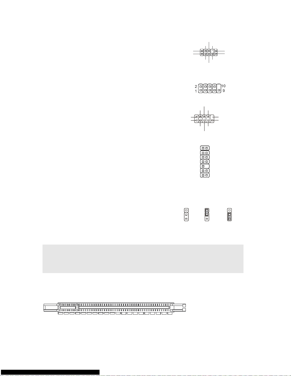
84
フロントパネルオーディオコネクタ:
JAUD1
フロントパネルオーディオピンヘッダを使用すると、フロンと
パネルからのオーディオ出力か可能になります。ピン配列は
Intel® I/O コネクタデザインガイドに準拠しています。
(2)GND
VCC5
MIC2_JD
NC
(1)MIC_L
Line-out_R
Line-out_L(9)
Line_JD(10)
(2)GND
MIC_R
Front to Sense
SPI デバッギングコネクタ: JSPI1
このコネクタは外部のデバッギングを接続するためです。
シリアルポートコネクタ: JCOM1
モデルによっては JCOM1 用のピンヘッダーを搭載していま
す。JCOM1 を使用する場合には別売りのブラケットが必要
です。16550A チップを採用し 16 バイト FIFO にてデータ転
送を行います。
Key,no pin
SIN
DTR
DSR
CTS
DCD
SOUT
GND
RTS
RI
(10)
(2)
(1) (9)
TPM モジュールコネクタ: JTPM1(オプ
ション)
このコネクタは TPM (Trusted Platform Module)モジュール
を接続します。詳細については TPM セキュリティプラットホー
ムマニュアルを参照してください。
KEY
GND
GND
14
3Vdual/ 3V_STB
2
VCC3
SIRQ
VCC5
LCLK
1
LRST#
LAD0
LAD1
LAD2
LAD3
LFRAME#
13
クリア CMOS ジャンパ: JBAT1
本製品には CMOS RAM が搭載されており、内蔵電池から
電気が供給されることでシステム情報や BIOSの設定を保持
しています。この CMOS RAM に蓄えられたデバイス情報に
よって、OS を迅速に起動させることが可能になります。シス
テム設定をクリアしたい場合、クリア CMOS ジャンパでデー
タをクリアします。
Keep Data
Clear Data
2
2 2
3
3 3
1
1 1
注意:
CMOS をクリアするには、システムがオフの間にピン 2-3 をショート(短絡)します。次いでピン
1-2 をショートに戻します。システム起動時の CMOS のクリアは絶対止めて下さい。マザーボー
ドの破損や火災などに及ぶ危険があります。必ず電源コードを抜いで下さい。
PCI Express スロット
PCI Express スロットは PCI Express インターフェイス拡張カードをサポートします。
PCI Express x 16 スロットは 4.0 GB/s までの転送速度をサポートします。
Page 91

85
PCI スロット
PCI スロットは最も汎用性の高い拡張スロットで、対応する様々な拡張カードが発売されていま
す。
注意:
拡張カードの取り外しに際しては、必ず最初に電源コードをコンセントから抜いてください。拡張
カードに添付されているマニュアルを読んで、ジャンパ、スイッチ、BIOS など必要なハードウェ
ア設定、ソフトウェア設定を行ってください。
PCI 割り込み要求ルーティング
IRQ(interrupt request line の省略形、アイアールキューと発音します)は、デバイスが割り込み
信号をマイクロプロセッサに送信するためのハードウェア回線です。PCI の IRQ ピンは通常 PCI
バス INT A#から INT D#ピンに下表のように接続されています:
Order1 Order2 Order3 Order4
PCI Slot1 INT A# INT B# INT C# INT D#
PCI Slot2 INT B# INT C# INT D# INT A#
BIOS セットアップ
コンピューターを起動するとシステムは POST (Power On Self Test)過程に入ります。下記のメッ
セージが画面に表示されている間に<DEL>キーを押すと設定画面に入ることができます。
Press DEL to enter SETUP
<DEL>を押す前にこのメッセージが消えてしまった場合、電源を再投入するか<RESET>を押し
てシステムを再起動してください。<Ctrl>と<Alt>と<Delete>を同時に押しても再起動できます。
Page 92
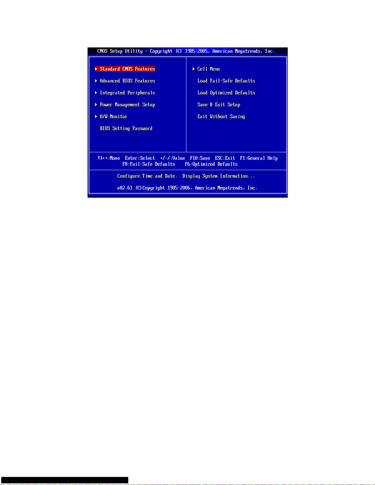
86
メインページ
Standard CMOS Features
日時などシステムの基本的な設定します。
Advanced BIOS Features
システム拡張機能の設定を行います。
Integrated Peripherals
IDE,シリアル、バラレルなどの各 I/O ポートの設定をします。
Power Management Setup
電源管理に関する設定を行います。
H/W Monitor
CPU 温度やファン回転数、警告表示などが確認できます。
BIOS Setting Password
パスワードを設定します。
Cell Menu
周波数/電圧コントロールの設定が表示されます。
Load Fail-Safe Defaults
工場出荷時の BIOS デフォルト値をロードできます。
Load Optimized Defaults
安定性を重視した BIOS 設定値をロードします。
Save & Exit Setup
変更した CMOS 設定値を保存してセットアップを終了します。
Exit Without Saving
変更した CMOS 設定値を保存せずにセットアップを終了します。
Page 93

87
Cell Menu
Current CPU Frequency
この項目で CPU の周波数を参照できます。(読取専用)
Current DRAM Frequency
この項目でメモリの周波数を参照できます。(読取専用)
Intel EIST
Enhanced Intel Speed Step 技術でマイクロプロセッサのパフォーマンスレベルを設定します。PC
がバッテリーで動作しますか AC 電源で動作しますかを決定します。CPU の倍率を調整したい場
合には、[Disabled]に設定します。この機能をサポートする CPU をインストールした後、このフィー
ルドが利用できます。
Adjust CPU FSB Frequency (MHz)
[Auto Detect CPU Frequency]項目を[Disable]に設定すると、手動で CPU FSB 周波数を調整で
きます。
Adjusted CPU Frequency
この項目で CPU の周波数(FSB x倍率)を調整できます。(倍率変更は対応 CPU 使用時のみ可
能)
Advance DRAM Configuration > DRAM CAS# Latency
ここでは DRAM が読み込みコマンドを受信した後、読み込みを開始するまでのタイミング遅延で
ある CAS レイテンシを設定します。[2.5T]は[2T]より、安定したパフォーマンスを提供できます。
[By SPD]に設定すると、DRAM CAS# Latency が自動的に有効にされ、DRAM モジュールの SPD
EEPROM 配列に基づいた BIOS に決定されます。
FSB/Memory Ratio
[Auto Detect DRAM Frequency]項目を[Disable]に設定すると、手動でメモリの FSB/倍率を調整
できます。
Page 94

88
Adjusted DDR Memory Frequency
この項目で調整した DRAM 周波数を参照できます。(読取専用)
Adjust PCI-E Frequency (MHz)
この項目で PCIE 周波数を選択し(MHz)、オーバークロックすることができます。
Auto Disable DIMM/PCI Frequency
[Enabled]に設定すると、システムは DIMM と PCI スロットからクロックを除去し、電磁妨害を最小
化します(EMI)。
Spread Spectrum
クロックジェネレータがクロック信号を生成する際に、スパイクと呼ばれる電磁妨害ノイズ(EMI)も
同時に生成されます。通常使用時は Disabled に設定することでシステムの安定性と性能を最適
化できますが、万が一電波妨害などが発生した場合は Spread Spectrum 機能を Enabled に設
定して障害を軽減させることができます。但し、オーバークロック動作実験を行う際は、必ず
Disabled に設定し、できるだけクロック信号の精度を高めた方が良いケースが多いです。
注意:
特に電波障害などの問題が無い場合は、システムの安定性と性能を確保するために[Disabled]
に設定して下さい。また、電波障害などが発生した場合は、必ず[Enabled]に設定して障害の軽
減に努めて下さい。
Spread Spectrum の値は大きければ大きいほどノイズ除去効果が高まりますが、システムの安
定度は低下します。
オーバークロック動作実験をする場合は、必ず[Disabled]に設定して下さい。
Load Optimized Defaults
安定した性能を与えるために、マザーボードが提供したデフォルト値をロードできます。
.
Page 95

有毒有害物质或元素名称及含量标识
有毒有害物质或元素
部件名称
铅(Pb) 汞(Hg) 镉(Cd) 六价铬(Cr(VI)) 多溴联苯(PBB) 多溴二苯醚(PBDE)
PCB 板 ○ ○ ○ ○ ○ ○
结构件 ○ ○ ○ ○ ○ ○
芯 片 × ○ ○ ○ ○ ○
连接器 × ○ ○ ○ ○ ○
被动电子元器件 × ○ ○ ○ ○ ○
线材 ○ ○ ○ ○ ○ ○
O:表示该有毒有害物质在该部件所有均质材料中的含量均在 SJ/T11363-2006 规定的限量要求以下。
X:表示该有毒有害物质至少在该部件的某一均貭材料中的含量超出 SJ/T11363-2006 规定的限量要求。
附记 : 请参照
‧含铅的电子组件。
‧钢合金中铅的含量达 0.35%,铝合金中含量达 0.4%,铜合金中的含量达 4%。
‧-铅使用于高熔点之焊料时(即铅合金之铅含量大于或等于 85%)
-铅使用于电子陶瓷零件。
‧含铅之焊料,用于连接接脚(pins)与微处理器(microprocessors)封装,此焊料由两个以上元素所组成且
含量介于 80~85%。
‧含铅之焊料使用于集成电路覆晶封装(Flip Chippackages)内部;介于半导体芯片和载体间,来完成电
力连结。
 Loading...