

Page 1
English
T:Lin e-In
M:L ine- Ou t
B:M ic-In
PCI _E1
JBAT1 JTP M1
JAU D1
JUS B1
JUS B2
JCI 1
SYS F
AN
1
JPW R1
CPU FAN1
JCO M1
SATA1 SATA2
JFP 1
JPW R2
BUZ 1
DIM M1
DIM M2
T: mous e
B:k eyboa rd
T: LAN Ja ck
B: US B2.0 po rts
T: VGA
B: DV I-D
USB 3.0 por ts
HDM I port
MIN I_PCI E_
1
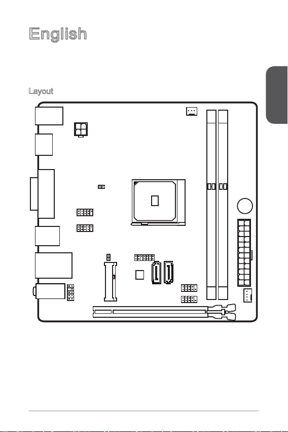
Thank you for choosing the AM1I Series (MS-7865 v2.X) Mini-ITX motherboard. The
AM1I Series motherboards are designed to t the advanced AMD AM1 processor,
the AM1I Series motherboards deliver a high performance and professional desktop
platform solution.
Layout
English
11
Page 2
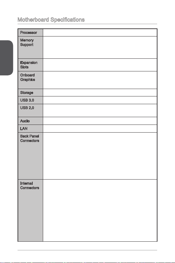
Motherboard Specications
Processor AMD Socket AM1 Processors■
Memory
Support
English
Expansion
Slots
Onboard
Graphics
Storage 2x SATA 6Gb/s ports■
USB 3.0 2x USB 3.0 ports on the back panel■
USB 2.0 6x USB 2.0 ports (2 ports on the back panel, 4 ports available
Audio Realtek® ALC887 Codec■
LAN Realtek® RTL8111G Gigabit LAN controller■
Back Panel
Connectors
Internal
Connectors
2x DDR3 memory slots supporting up to 32GB
■
Supports DDR3 1600/ 1333/ 1066 MHz
■
Single channel memory architecture
■
Supports non-ECC, un-buered memory
■
1x PCIe 2.0 x16 slot, supports x4 speed
■
1x Mini-PCIe slot
■
1x VGA port, supporting a maximum resolution of 1920x1200
■
1x HDMI port, supporting a maximum resolution of 4096x2160
■
1x DVI-D port, supporting a maximum resolution of 1920x1200
■
■
through the internal USB connectors)
1x PS/2 keyboard port
■
1x PS/2 mouse port
■
1x VGA port
■
1x DVI-D port
■
1x HDMI port
■
2x USB 3.0 ports
■
2x USB 2.0 ports
■
1x LAN (RJ45) port
■
3x audio jacks
■
1x 24-pin ATX main power connector
■
1x 4-pin ATX 12V power connector
■
2x SATA 6Gb/s connectors
■
2x USB 2.0 connectors (supports additional 4 USB 2.0 ports)
■
1x 3-pin CPU fan connector
■
1x 4-pin system fan connector
■
1x Front panel audio connector
■
1x Serial port connector
■
1x TPM connector
■
1x System panel connector
■
1x Chassis Intrusion connector
■
1x Clear CMOS jumper
■
12
Page 3
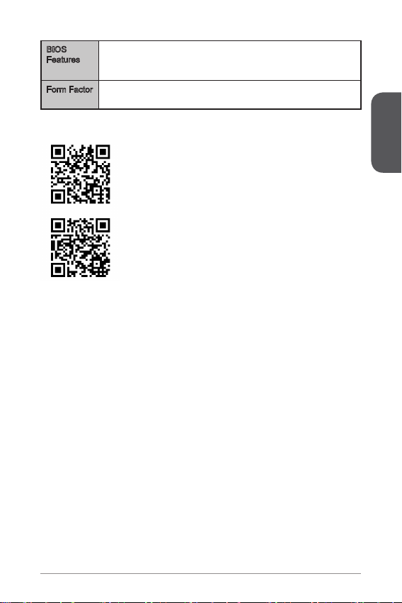
BIOS
Features
Form Factor Mini-ITX Form Factor
UEFI AMI BIOS
■
ACPI 5.0, PnP 1.0a, SM BIOS 2.7, DMI 2.0
■
Multi-language
■
■
6.7 in. x 6.7 in. (17.0 cm x 17.0 cm)
■
For the latest information about CPU, please visit
http://www.msi.com/service/cpu-support/
For more information on compatible components, please
visit http://www.msi.com/service/test-report/
English
13
Page 4

Back Panel
®
PS/2 Mouse
English
HDMI
PS/2 Keyboard USB 2.0
VGA
USB 3.0
DVI-D
LAN LED Indicator
LINK/ACT
LED
LED LED Status Description
Link/ Activity LED
Speed LED
SPEED
LED
O No link
Yellow Linked
Blinking Data activity
O 10 Mbps connection
Green 100 Mbps connection
Orange 1 Gbps connection
Audio 2, 4, 6 or 8-channel conguration
Port 2-channel 4-channel 6-channel 8-channel
Blue Line in RS-Out RS-Out RS-Out
Green Line out FS-Out FS-Out FS-Out
Pink Mic Mic CS-Out CS-Out
Front audio - - - SS-Out
LAN
Audio
14
Page 5
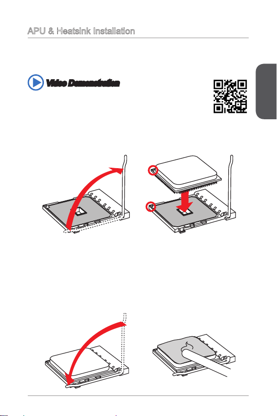
APU & Heatsink Installation
When installing an APU, always remember to install an APU heatsink. An APU
heatsink is necessary to prevent overheating and maintain system stability. Follow
the steps below to ensure correct APU and heatsink installation. Wrong installation
can damage both the APU and the motherboard.
Video Demonstration
Watch the video to learn how to install APU & heatsink at the address
below.
http://youtu.be/s--YUBNkHc8
1. Pull the lever sideways away from the socket. Make sure to raise the lever up to
a 90-degree angle.
2. Look for the gold arrow of the APU. The gold arrow should point as shown in the
picture. The APU can only t in the correct orientation.
3. If the APU is correctly installed, the pins should be completely embedded into
the socket and can not be seen. Please note that any violation of the correct
installation procedures may cause permanent damages to your motherboard.
4. Press the APU down rmly into the socket and close the lever. As the APU is
likely to move while the lever is being closed, always close the lever with your
ngers pressing tightly on top of the APU to make sure the APU is properly and
completely embedded into the socket.
5. Evenly spread a thin layer of thermal paste (or thermal tape) on the top of the
APU. This will help in heat dissipation and prevent APU overheating.
English
15
Page 6
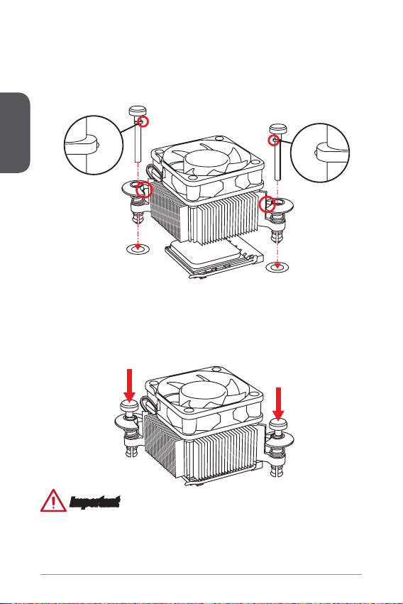
6. Locate the CPUFAN connector on the motherboard.
7. Place the heatsink on the motherboard with the fan’s cable facing towards the
fan connector and the fasteners matching the holes on the motherboard.
8. Align the protrusion of the push-pin with the notch of the fastener as shown in
the picture. Insert the two push-pins into the two fasteners.
English
9. Push down the push-pins until the two fasteners get wedged into the holes on
the motherboard. Press the two fasteners down to fasten the heatsink. As each
fastener locks into position a click should be heard.
10. Inspect the motherboard to ensure that the fastener-ends have been properly
locked in place.
11. Attach the fan cable to the CPUFAN connector on the motherboard.
Important
Conrm that the APU cooler has formed a tight seal with the APU before booting
•
your system.
Please refer to the documentation in the APU cooler package for more details
•
about APU cooler installation.
16
Page 7

Memory
These DIMM slots are used for installing memory modules. For more information on
compatible components, please visit http://www.msi.com/service/test-report/
DIMM1
DIMM2
Video Demonstration
Watch the video to learn how to install memories at the address below.
http://youtu.be/76yLtJaKlCQ
Important
DDR3 memory modules are not interchangeable with DDR2, and the DDR3
•
standard is not backward compatible. Always install DDR3 memory modules in
DDR3 DIMM slots.
Due to chipset resource usage, the system will only detect up to 31+ GB of
•
memory (not full 32 GB) when all DIMM slots have 8GB memory modules installed.
English
17
Page 8

Internal Connectors
13. +3. 3
V
1.+ 3.3
V
14. -12 V
2.+ 3.3
V
15. Gro und
3
.Gr oun d
16. PS- ON
#
4.+ 5
V
17. Gro und
5
.Gr oun d
18. Gro und
6.+ 5
V
19. Gro und
7
.Gr oun d
22. +5
V
10. +12 V
20. Res
8.P W
R O
K
23. +5
V
11
.+1 2V
21. +5
V
9.5 VSB
24. Gro und
12. +3. 3
V
4.+ 12V
2
.Gr oun d
3.+ 12V
1
.Gr oun d
1
.
D
C
D
3
.
S
O
U
T
1
0
.
N
o
P
i
n
5
.
G
r
o
u
n
d
7
.
R
T
S
9
.
R
I
8
.
C
T
S
6
.
D
S
R
4
.
D
T
R
2
.
S
I
N
JPWR1~2: ATX Power Connectors
These connectors allow you to connect an ATX power supply. To connect the ATX
power supply, align the power supply cable with the connector and rmly press the
cable into the connector. If done correctly, the clip on the power cable should be
English
hooked on the motherboard’s power connector.
Video Demonstration
Watch the video to learn how to install power supply connectors.
http://youtu.be/gkDYyR_83I4
JPWR1
JPWR2
Important
Make sure that all the power cables are securely connected to a proper ATX power
supply to ensure stable operation of the motherboard.
JCOM1: Serial Port Connector
This connector is a 16550A high speed communication port that sends/receives 16
bytes FIFOs. You can attach a serial device.
18
Page 9
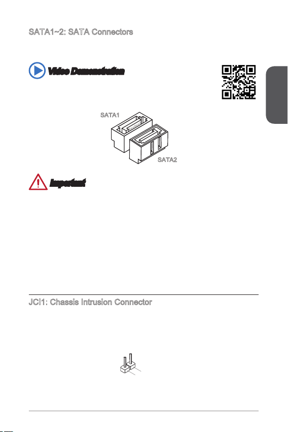
SATA1~2: SATA Connectors
2
.
C
I
N
T
R
U
1
.
G
r
o
u
n
d
This connector is a high-speed SATA interface port. Each connector can connect to
one SATA device. SATA devices include disk drives (HDD), solid state drives (SSD),
and optical drives (CD/ DVD/ Blu-Ray).
Video Demonstration
Watch the video to learn how to Install SATA HDD.
http://youtu.be/RZsMpqxythc
SATA1
SATA2
Important
Many SATA devices also need a power cable from the power supply. Such devices
•
include disk drives (HDD), solid state drives (SSD), and optical drives (CD / DVD /
Blu-Ray). Please refer to the device’s manual for further information.
Many computer cases also require that large SATA devices, such as HDDs, SSDs,
•
and optical drives, be screwed down into the case. Refer to the manual that came
with your computer case or your SATA device for further installation instructions.
Please do not fold the SATA cable at a 90-degree angle. Data loss may result
•
during transmission otherwise.
SATA cables have identical plugs on either sides of the cable. However, it is
•
recommended that the at connector be connected to the motherboard for space
saving purposes.
JCI1: Chassis Intrusion Connector
This connector connects to the chassis intrusion switch cable. If the computer case
is opened, the chassis intrusion mechanism will be activated. The system will record
this intrusion and a warning message will ash on screen. To clear the warning, you
must enter the BIOS utility and clear the record.
English
19
Page 10

CPUFAN1,SYSFAN1: Fan Power Connectors
1
.Gr ou nd
2.+ 12 V
3.S en s
e
1
.Gr ou nd
2.+ 12 V
3.S en s
e
4.S pe ed
C
ont ro
l
1.M I
C L
3.M I
C R
10. He ad
P
hon e
Det ec ti on
5.H ea d
P
hon e
R
7.S EN SE _SE N
D
9.H ea d
P
hon e
L
8.N o
Pi
n
6.M I
C D
ete ct io n
4.N C
2
.Gr ou nd
The fan power connectors support system cooling fans with +12V. If the motherboard
has a System Hardware Monitor chipset on-board, you must use a specially designed
fan with a speed sensor to take advantage of the fan control. Remember to connect
all system fans. Some system fans may not connect to the motherboard and will
instead connect to the power supply directly. A system fan can be plugged into any
available system fan connector.
English
CPUFAN1
Important
Please refer to your processor’s ocial website or consult your vendor to nd
•
recommended CPU heatsink.
These connectors support Smart Fan Control with liner mode. The Command
•
Center utility can be installed to automatically control the fan speeds according to
the CPU’s and system’s temperature.
If there are not enough ports on the motherboard to connect all system fans,
•
adapters are available to connect a fan directly to a power supply.
Before rst boot up, ensure that there are no cables impeding any fan blades.
•
JAUD1: Front Panel Audio Connector
This connector allows you to connect the front audio panel located on your computer
case. This connector is compliant with the Intel® Front Panel I/O Connectivity Design
Guide.
20
SYSFAN1
Page 11

JFP1: System Panel Connectors
1.
+
3.-
10. No
Pi
n
5.
Res et
S
wit ch
HDD
LE
D
P
owe r
Swi tc h
P
owe r
LE
D
7.
+
9.R es erv e
d
8.
-
6.
+
4.-
2.+
1
.
V
C
C
3
.
U
S
B
0
-
1
0
.
NC
5
.
U
S
B
0
+
7
.
G
r
o
u
n
d
9
.
N
o
P
i
n
8
.
G
r
o
u
n
d
6
.
U
S
B
1
+
4
.
U
S
B
1
-
2
.
V
C
C
These connectors connect to the front panel switches and LEDs. The JFP1
connector is compliant with the Intel® Front Panel I/O Connectivity Design Guide.
When installing the front panel connectors, please use the optional M-Connector to
simplify installation. Plug all the wires from the computer case into the M-Connector
and then plug the M-Connector into the motherboard.
Video Demonstration
Watch the video to learn how to Install front panel connectors.
http://youtu.be/DPELIdVNZUI
JFP1
Important
On the connectors coming from the case, pins marked by small triangles are
•
positive wires. Please use the diagrams above and the writing on the optional MConnectors to determine correct connector orientation and placement.
The majority of the computer case’s front panel connectors will primarily be
•
plugged into JFP1.
JUSB1~2: USB 2.0 Expansion Connectors
This connector is designed for connecting high-speed USB peripherals such as USB
HDDs, digital cameras, MP3 players, printers, modems, and many others.
English
Important
Note that the VCC and GND pins must be connected correctly to avoid possible
damage.
21
Page 12

JTPM1: TPM Module Connector
10. No
Pi
n
14. Groun d
8.5 V
P
owe r
12. Groun d
6.S erial
IR
Q
4.3 .3V
P
owe r
2.3 V
Sta ndby
p
owe r
1.L P
C C
loc
k
3.L P
C
Res e
t
5.L P
C a
ddr es
s &
dat a
pin 0
7.L P
C a
ddr es
s &
dat a
p
in1
9.L P
C a
ddr es
s &
dat a
pin 2
11
.LP C
a
ddr es
s &
dat a
p
in3
13. LP
C
Fra m
e
This connector connects to a TPM (Trusted Platform Module). Please refer to the
TPM security platform manual for more details and usages.
English
JBAT1: Clear CMOS Jumper
There is CMOS RAM onboard that is external powered from a battery located on the
motherboard to save system conguration data. With the CMOS RAM, the system
can automatically boot into the operating system (OS) every time it is turned on. If
you want to clear the system conguration, set the jumpers to clear the CMOS RAM.
1
1
Keep Data Clear Data
Important
You can clear the CMOS RAM by shorting this jumper while the system is o.
Afterwards, open the jumper . Do not clear the CMOS RAM while the system is on
because it will damage the motherboard.
22
Page 13

PCI_E1: PCIe x16 Expansion Slot
The PCIe slot supports the PCIe interface expansion card.
MINI_PCI_E1: Mini-PCIe Expansion Slot
The Mini-PCIe slot supports the Mini-PCIe interface expansion card.
Important
When adding or removing expansion cards, always turn o the power supply and
unplug the power supply power cable from the power outlet. Read the expansion
card’s documentation to check for any necessary additional hardware or software
changes.
English
23
Page 14

BIOS Setup
The default settings oer the optimal performance for system stability in normal
conditions. You may need to run the Setup program when:
An error message appears on the screen during the system booting up, and
■
requests you to run SETUP.
English
You want to change the default settings for customized features.
■
Important
Please load the default settings to restore the optimal system performance and
•
stability if the system becomes unstable after changing BIOS settings. Select the
"Restore Defaults" and press <Enter> in BIOS to load the default settings.
If you are unfamiliar with the BIOS settings, we recommend that you keep the
•
default settings to avoid possible system damage or failure booting due to
inappropriate BIOS conguration.
Entering BIOS Setup
Power on the computer and the system will start the Power On Self Test (POST)
process. When the message below appears on the screen, press <DEL> key to enter
BIOS:
Press DEL key to enter Setup Menu, F11 to enter Boot Menu
If the message disappears before you respond and you still need to enter BIOS,
restart the system by turning the computer OFF then back ON or pressing the
RESET button. You may also restart the system by simultaneously pressing <Ctrl>,
<Alt>, and <Delete> keys.
Control Keys
↑ ↓ ← → Move between items
Enter Select an item
+ - Change the value of the selected item
ESC Exit
F1 Display the general help
F4 Display CPU specications
F5 Memeory-Z
F6 Load optimized defaults
F8 Load an OC prole from USB
F9 Save an OC prole to USB
F10 Exit
24
Page 15

OC Menu
Important
Overclocking your PC manually is only recommended for advanced users.
•
Overclocking is not guaranteed, and if done improperly, can void your warranty or
•
severely damage your hardware.
If you are unfamiliar with overclocking, we advise you to use OC Genie for easy
•
overclocking.
Current CPU/ DRAM/ NB/ GPU Frequency
▶
These items show the current frequencies of installed CPU, Memory and. Read-only.
Adjust CPU Ratio [Auto]
▶
Sets the CPU ratio that is used to determine CPU clock speed. This item can only be
changed if the processor supports this function.
Adjusted CPU Frequency
▶
Shows the adjusted CPU frequency. Read-only.
DRAM Frequency [Auto]
▶
Sets the DRAM frequency. Please note the overclocking behavior is not guaranteed.
Adjusted DRAM Frequency
▶
Shows the adjusted DRAM frequency. Read-only.
DRAM Timing Mode [Auto]
▶
Selects the memory timing mode.
[Auto] DRAM timings will be determined based on SPD (Serial Presence
[Link] Allows user to congure the DRAM timing manually for all memory
Detect) of installed memory modules.
channel.
English
25
Page 16

[UnLink] Allows user to congure the DRAM timing manually for respective
Advanced DRAM Conguration
▶
Press <Enter> to enter the sub-menu. This sub-menu will be activated after setting
[Link] or [Unlink] in “DRAM Timing Mode”. User can set the memory timing for each
memory channel. The system may become unstable or unbootable after changing
English
memory timing. If it occurs, please clear the CMOS data and restore the default
settings. (Refer to the Clear CMOS jumper/ button section to clear the CMOS data,
and enter the BIOS to load the default settings.)
Spread Spectrum
▶
This function reduces the EMI (Electromagnetic Interference) generated by
modulating clock generator pulses.
[Enabled] Enables the spread spectrum function to reduce the EMI
[Disabled] Enhances the overclocking ability of CPU Base clock.
memory channel.
(Electromagnetic Interference) problem.
Important
If you do not have any EMI problem, leave the setting at [Disabled] for optimal
•
system stability and performance. But if you are plagued by EMI, select the value
of Spread Spectrum for EMI reduction.
The greater the Spread Spectrum value is, the greater the EMI is reduced, and
•
the system will become less stable. For the most suitable Spread Spectrum value,
please consult your local EMI regulation.
Remember to disable Spread Spectrum if you are overclocking because even a
•
slight jitter can introduce a temporary boost in clock speed which may just cause
your overclocked processor to lock up.
DRAM Voltage [Auto]
▶
Sets the value for appointed voltage related to memory. If set to "Auto", BIOS will set
the voltage automatically or you can set it manually.
CPU Memory Changed Detect [Enabled]
▶
Enables or disables the system to issue a warning message during boot when the
CPU or memory has been replaced.
[Enabled] The system will issue a warning message during boot and than
[Disabled] Disables this function and keeps the current BIOS settings.
OC Retry Count
▶
When overclocking has failed, setting this item as [1,3] will allow system to reboot
1/ 3 times with the same overclocked conguration. If overclocking has failed every
time, the system will restore the defaults.
Overclocking Proles
▶
Overclocking Proles management. Press <Enter> to enter the sub-menu.
needs to load the default settings for new devices.
26
Page 17

Overclocking Profile 1/ 2/ 3/ 4/ 5/ 6
▶
Overclocking Prole 1/ 2/ 3/ 4/ 5/ 6 management. Press <Enter> to enter the
sub-menu.
OC Profile Save to USB
▶
Saves OC prole to the USB ash disk drive. The USB ash disk should be
FAT32 format only.
OC Profile Load from USB
▶
Loads OC prole from the USB ash disk drive. The USB ash disk should be
FAT32 format only.
CPU Specications
▶
Press <Enter> to enter the sub-menu. This sub-menu displays the information of
installed CPU. You can also access this information menu at any time by pressing
[F4]. Read only.
CPU Technology Support
▶
Press <Enter> to enter the sub-menu. The sub-menu shows what the key
features does the installed CPU support. Read only.
MEMORY-Z
▶
Press <Enter> to enter the sub-menu. This sub-menu displays all the settings and
timings of installed memory.
CPU Features
▶
Press <Enter> to enter the sub-menu.
AMD Cool’n’Quiet [Auto]
▶
Enabled or disabled AMD Cool’n’Quiet function.
[Auto] Depends on AMD Design.
[Enable] Enables AMD Cool’n’Quiet function. The Cool’n’Quiet
[Disabled] Disables this function.
technology can eectively and dynamically lower CPU speed
and power consumption.
Important
When adjust CPU Ratio setting then Cool’n’Quiet function will be disabled
automatically. For CPU which supports the Turbo Core Tech., please set AMD Turbo
Core Technology and AMD Cool’n’Quiet as Disabled to retain the default CPU core
speed.
SVM Mode [Enabled]
▶
Enables or disables CPU Virtualization.
[Enabled] Enables CPU Virtualization and allows a platform to run
[Disabled] Disables this function.
multiple operating systems in independent partitions. The
system can function as multiple systems virtually.
English
27
Page 18

English
Core C6 State [Enabled]
▶
Enables or disables C6 state support.
[Enabled] When the CPU enters C6 state, all cores will save
[Disabled] Disables this function.
architectural state and reduce core voltages to zero volts.
Wake up the CPU from C6 state will take a lot longer.
28
 Loading...