

Page 1

AG240 Series
All-in-One (AIO) PC
MS-AE67 System
G52-AE671X1
Page 2

Contents
Copyright Notice ������������������������������������������������������������������������������������������������������iii
Trademarks �������������������������������������������������������������������������������������������������������������iii
Revision ������������������������������������������������������������������������������������������������������������������iii
Upgrade and Warranty ��������������������������������������������������������������������������������������������iv
Acquisition of Replaceable Parts ����������������������������������������������������������������������������iv
Technical Support ���������������������������������������������������������������������������������������������������iv
Green Product Features ������������������������������������������������������������������������������������������iv
Environmental Policy �������������������������������������������������������������������������������������������� v
Chemical Substances Information �������������������������������������������������������������������������� v
Battery Information �������������������������������������������������������������������������������������������������� v
Safety Instructions ���������������������������������������������������������������������������������������������������vi
CE Conformity ������������������������������������������������������������������������������������������������������� viii
FCC-B Radio Frequency Interference Statement ������������������������������������������������� viii
WEEE Statement �������������������������������������������������������������������������������������������������� viii
1. Overview ............................................................ 1-1
Packing Contents �������������������������������������������������������������������������������������������������1-2
ii
System Overview ������������������������������������������������������������������������������������������������� 1-3
Component Replacement & Upgrade ������������������������������������������������������������������ 1-9
2. Getting Started ................................................... 2-1
Safety & Comfort Tips ������������������������������������������������������������������������������������������2-2
Hardware Setup ��������������������������������������������������������������������������������������������������� 2-3
3. System Operations ............................................. 3-1
On-Screen Display (OSD) ������������������������������������������������������������������������������������ 3-2
Power Management ���������������������������������������������������������������������������������������������3-5
Network Connection (Windows 7) ������������������������������������������������������������������������ 3-7
Network Connection (Windows 8�x) �������������������������������������������������������������������
System Recovery (Windows 7) ��������������������������������������������������������������������������3-13
System Recovery (Windows 8�x) ����������������������������������������������������������������������� 3-23
3-10
A. Troubleshooting ................................................. A-1
Page 3

Preface
Copyright Notice
The material in this document is the intellectual property of MICRO-STAR
INTERNATIONAL� We take every care in the preparation of this document, but no
guarantee is given as to the correctness of its contents� Our products are under continual
improvement and we reserve the right to make changes without notice�
Trademarks
All trademarks are the properties of their respective owners�
Revision
Revision Date
V1�0 2014/02
iii
Page 4

Upgrade and Warranty
Please note that certain components preinstalled in the product may be upgradable
or replaceable by user’s request� For any further information about the product users
purchased, please contact the local dealer� Do not attempt to upgrade or replace any
component of the product if you are not an authorized dealer or service center, since it
may cause the warranty void� It is strongly recommended that you contact the authorized
dealer or service center for any upgrade or replace service�
Acquisition of Replaceable Parts
Please be noticed that the acquisition of replaceable parts (or compatible ones) of
the product users purchased in certain countries or territories may be fullled by the
manufacturer within 5 years at most since the product has been discontinued, depending
on the ocial regulations declared at the time�
Please contact the manufacturer via http://support�msi�com/ for the detailed information
about the acquisition of spare parts�
Technical Support
If a problem arises with your system and no solution can be obtained from the user’s
manual, please contact your place of purchase or local distributor� Alternatively, please
try the following help resources for further guidance�
iv
Visit the MSI website for technical guide, BIOS updates, driver updates and
◙
other information via http://www�msi�com/service/download/
Contact our technical sta via http://support�msi�com/
◙
Green Product Features
Reduced energy consumption during use and stand-by
◙
Limited use of substances harmful to the environment and health
◙
Easily dismantled and recycled
◙
Reduced use of natural resources by encouraging recycling
◙
Extended product lifetime through easy upgrades
◙
Reduced solid waste production through take-back policy
◙
Page 5
Preface
Environmental Policy
The product has been designed to enable proper reuse of parts
◙
and recycling and should not be thrown away at its end of life�
Users should contact the local authorized point of collection for
◙
recycling and disposing of their end-of-life products�
Visit the MSI website and locate a nearby distributor for further recycling
◙
information�
◙
Users may also reach us at gpcontdev@msi�com for information regarding
proper Disposal, Take-back, Recycling, and Disassembly of MSI products�
Chemical Substances Information
In compliance with chemical substances regulations, such as the EU REACH Regulation
(Regulation EC No� 1907/2006 of the European Parliament and the Council), MSI
provides the information of chemical substances in products at:
http://www�msi�com/html/popup/csr/evmtprtt_pcm�html
Battery Information
European Union:
Batteries, battery packs, and accumulators should not be
disposed of as unsorted household waste� Please use the
public collection system to return, recycle, or treat them in
compliance with the local regulations�
v
Taiwan:
For better environmental protection, waste batteries should
be collected separately for recycling or special disposal�
California, USA:
The button cell battery may contain perchlorate material and requires special
handling when recycled or disposed of in California�
For further information please visit:
http://www�dtsc�ca�gov/hazardouswaste/perchlorate/
Danger of explosion if battery is incorrectly replaced� Replace only with the
same or equivalent type recommended by the manufacturer�
Page 6
Safety Instructions
Read the safety instructions carefully and thoroughly�
◙
All cautions and warnings on the equipment or user’s manual should be
◙
noted�
Keep the User’s Guide that comes with the package for future reference�
Keep this equipment away from humidity and high temperature�
Lay this equipment on a reliable at surface before setting it up�
vi
Make sure that the power voltage is within its safety range and has been
◙
adjusted properly to the value of 100~240V before connecting the equipment
to the power outlet� Do not disable the protective earth pin from the plug�
The equipment must be connected to an earthed mains socket-outlet�
Always unplug the AC power cord before installing any add-on card or
◙
module to the equipment�
Always disconnect the AC power cord or switch the wall socket o if the
◙
equipment would be left unused for a certain time to achieve zero energy
consumption�
The ventilator on the enclosure is used for air convection and to prevent the
equipment from overheating� Do not cover the ventilator�
Do not leave the equipment in an unconditioned environment with a storage
temperature above 60OC (140OF) or below 0OC (32OF), which may damage the
equipment�
NOTE: The maximum operating temperature is around 40OC�
Page 7
Preface
Never pour any liquid into the opening that could damage or cause electrical
shock�
Place the power cord in a way that people are unlikely to step on it� Do not place
anything on the power cord�
When installing the coaxial cable to the TV Tuner, it is necessary to ensure
◙
that the metal shield is reliably connected to protective earthing system of
the building�
Cable distribution system should be grounded (earthed) in accordance with
◙
ANSI/NFPA 70, the National Electrical Code (NEC), in particular Section
820�93, Grounding of Outer Conductive Shield of a Coaxial Cable�
Always keep the strong magnetic or electrical objects away from the
equipment�
If any of the following situations arises, get the equipment checked by service
personnel:
The power cord or plug is damaged�
◙
Liquid has penetrated into the equipment�
◙
The equipment has been exposed to moisture�
◙
The equipment does not work well or you can not get it work according to
◙
user’s manual�
The equipment has dropped and damaged�
◙
The equipment has obvious sign of breakage�
◙
The optical storage devices are classied as CLASS 1 LASER PRODUCT� Use of
1�
controls or adjustments or performance of procedures other than those specied
is prohibited�
2�
Do not touch the lens inside the drive�
vii
Page 8
CE Conformity
Hereby, Micro-Star International CO�, LTD declares that this device is
in compliance with the essential safety requirements and other relevant
provisions set out in the European Directive�
FCC-B Radio Frequency Interference Statement
This equipment has been tested and found to comply with the limits for
a Class B digital device, pursuant to Part 15 of the FCC Rules� These
limits are designed to provide reasonable protection against harmful
interference in a residential installation� This equipment generates,
uses and can radiate radio frequency energy and, if not installed and
used in accordance with the instruction manual, may cause harmful interference to
radio communications� However, there is no guarantee that interference will not occur
in a particular installation� If this equipment does cause harmful interference to radio or
television reception, which can be determined by turning the equipment o and on, the
user is encouraged to try to correct the interference by one or more of the measures
listed below:
Reorient or relocate the receiving antenna�
■
Increase the separation between the equipment and receiver�
■
Connect the equipment into an outlet on a circuit dierent from that to which
viii
■
the receiver is connected�
Consult the dealer or an experienced radio/television technician for help�
■
Notice 1
The changes or modications not expressly approved by the party responsible for
compliance could void the user’s authority to operate the equipment�
Notice 2
Shielded interface cables and AC power cord, if any, must be used in order to comply
with the emission limits�
VOIR LA NOTICE D’INSTALLATION AVANT DE RACCORDER AU RESEAU�
This device complies with Part 15 of the FCC Rules� Operation is subject to the following
two conditions:
this device may not cause harmful interference, and
1�
this device must accept any interference received, including interference that may
2�
cause undesired operation�
WEEE Statement
Under the European Union (“EU”) Directive on Waste Electrical and
Electronic Equipment, Directive 2002/96/EC, which takes eect on August
13, 2005, products of “electrical and electronic equipment” cannot be
discarded as municipal waste anymore and manufacturers of covered
electronic equipment will be obligated to take back such products at the end
of their useful life�
Page 9

1
Overview
This system is integrated in design, selecting a stylish appearance with a mirror
screen, which displays the simplicity of modern individualism and the comfort
of home� With a touchscreen display, awless audio/video capabilities and
intuitive user interface, it blends technology with life, making computers easier
and more fun to use — suitable for the whole family�
Page 10
Overview
1-31-2
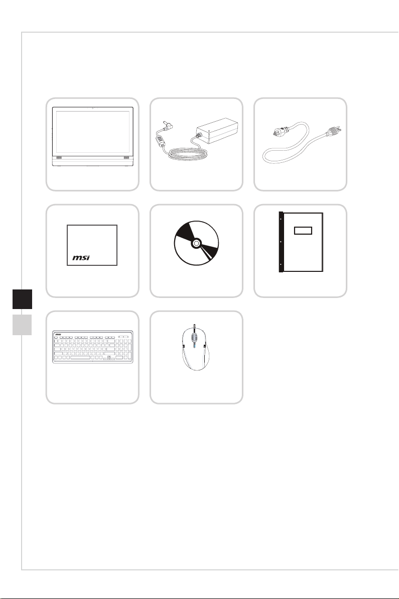
Packing Contents
All-in-One PC
Display Wiper
Keyboard (Optional)
AC/DC Adapter
Driver/ Utility Disc
Mouse (Optional)
AC Power Cord
User Manual &
Quick Guide
* Please contact us immediately if any of the items is damaged or missing�
* The illustrations are for reference only and your packing contents may slightly vary
depending on the model you purchased�
Page 11
Overview
1-31-2
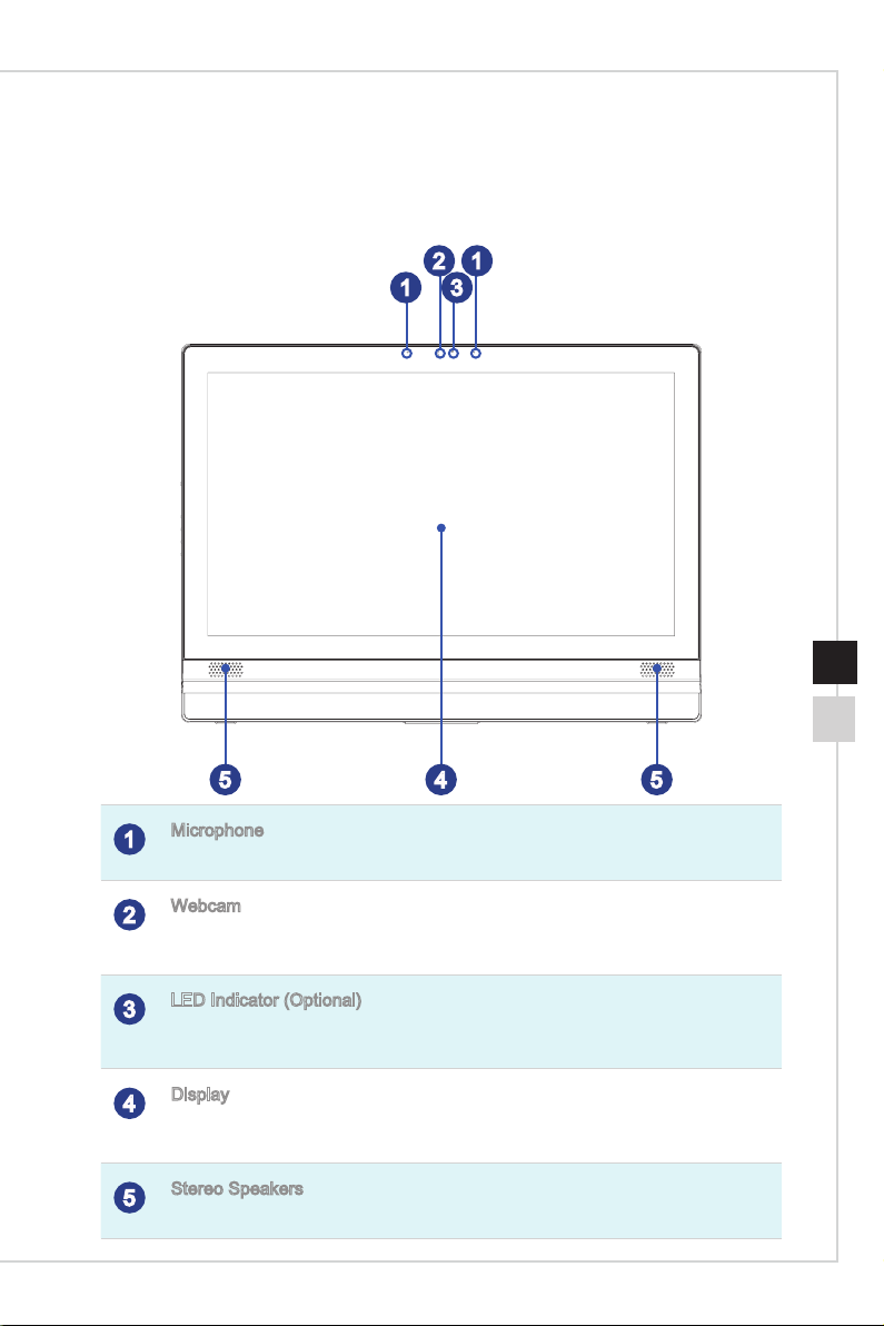
System Overview
Front View
2 1
31
Overview
1-31-2
545
Microphone
1
The built-in microphone can be used for video chatting online�
Webcam
2
The built-in webcam with the microphone can be used for picture taking, video recoding,
online conferencing and any other interactive applications�
LED Indicator (Optional)
3
The LED indicator indicates when it is recording� The LED indicator should be on when
device is capturing video and o when the device is not capturing video�
Display
4
The 23�6-inch LED-backlit display provides 1920 x 1080 Full HD resolution in a 16:9
widescreen format�
Stereo Speakers
5
The built-in stereo speakers deliver high quality sound blaster with stereo system�
Page 12
Overview
1-51-4
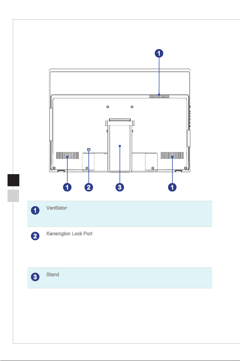
Rear View
1
1 1
2 3
Ventilator
1
The ventilator on the enclosure is used for air convection and to prevent the equipment
from overheating� Do not cover the ventilator�
Kensington Lock Port
2
This AIO PC provides a Kensington lock port, which allows users to secure the AIO PC
in place with a key or some mechanical PIN device and attached through a rubberised
metal cable� The end of the cable has a small loop which allows the whole cable to be
looped around a permanent object, such as a heavy table or other similar equipment,
thus securing the AIO PC in place�
Stand
3
Use this stand to position your system on a at and stable surface�
Page 13
Overview
1-51-4
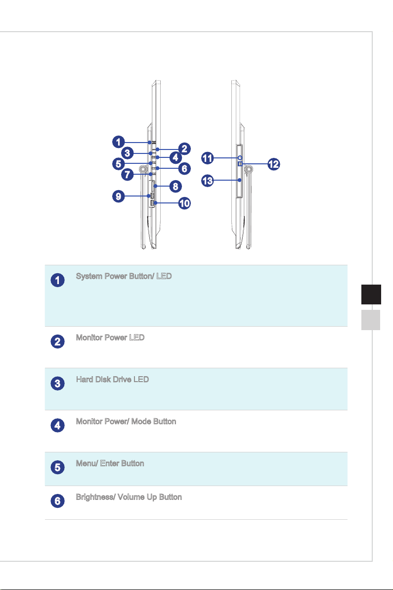
Side View
Overview
1
3
5
7
9
System Power Button/ LED
1
Press the system power button to turn the system on or o�
The power LED glows when the system is turned on and goes o when the system is
shut down� In terms of power saving, the LED blinks in S3 (Suspend to RAM) mode and
goes o in S4 (Suspend to Disk) mode�
Monitor Power LED
2
The power LED glows when the monitor is turned on and goes o when the monitor is
shut down�
Hard Disk Drive LED
3
This indicator shows the activity status of the HDD� It ashes when the system is
accessing data on the HDD and remains o when no disk activity is detected�
Monitor Power/ Mode Button
4
This button works both as the monitor power button and as the signal input switch
between PC & HDMI�
2
4
11
6
13
8
12
10
1-51-4
Menu/ Enter Button
5
Press this button to view the OSD menu or enter into the submenu�
Brightness/ Volume Up Button
6
Press this button to tune the brightness/ volume up�
Page 14
Overview
1-71-6
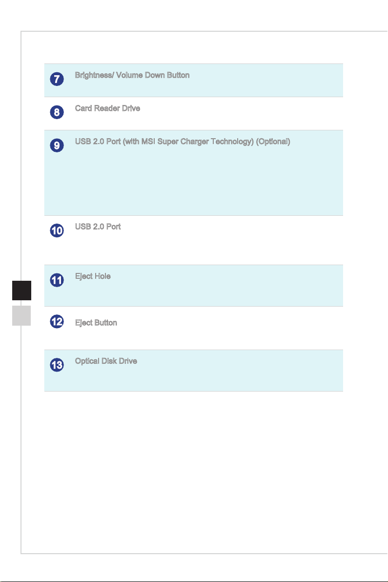
Brightness/ Volume Down Button
7
Press this button to tune the brightness/ volume down�
Card Reader Drive
8
The built-in card reader may support various types of memory cards�
USB 2�0 Port (with MSI Super Charger Technology) (Optional)
9
The USB (Universal Serial Bus) port is for attaching USB devices such as keyboard,
mouse, or other USB-compatible devices� It supports up to 480Mbit/s (Hi-Speed) data
transfer rate�
With MSI Super Charger Technology, not only does it function as normal USB 2�0 port,
but it also enables users to charge USB devices even when the system is turned o�
Users will no longer need to power on the system just to charge USB devices� Better yet,
it can reduce the charge time up to 40%, making life more ecient than ever�
USB 2�0 Port
10
The USB (Universal Serial Bus) port is for attaching USB devices such as keyboard,
mouse, or other USB-compatible devices� It supports up to 480Mbit/s (Hi-Speed) data
transfer rate�
Eject Hole
11
Insert a thin, straight object (such as a paper clip) into the eject hole to open the optical
disk drive manually if the eject button does not work�
12
Eject Button
Press the eject button to open the optical disk drive�
Optical Disk Drive
13
A DVD Super-Multi drive is integrated for your home entertainment (Blu-ray is
optional)�
Page 15
Overview
1-71-6
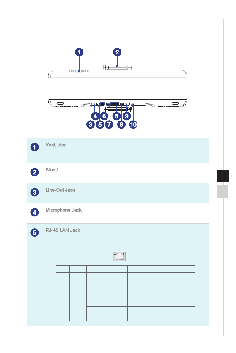
Top and Bottom View
Ventilator
1
The ventilator on the enclosure is used for air convection and to prevent the equipment
from overheating� Do not cover the ventilator�
Stand
2
Use this stand to position your system on a at and stable surface�
4
3
6 9
6
5
7
Overview
21
10
8
1-71-6
Line-Out Jack
3
This connector is provided for headphones or speakers�
Microphone Jack
4
This connector is provided for microphones�
RJ-45 LAN Jack
5
The standard RJ-45 LAN jack is provided for connection to the Local Area Network
(LAN)� You can connect a network cable to it�
Yellow Green/ Orange
LED Color LED State Condition
Left Yellow O LAN link is not established�
On (steady state) LAN link is established�
On (blinking) The computer is communicating with
Right Green O 10 Mbit/sec data rate is selected�
On 100 Mbit/sec data rate is selected�
Orange On 1000 Mbit/sec data rate is selected�
another computer on the LAN�
Page 16
Overview
1-91-8
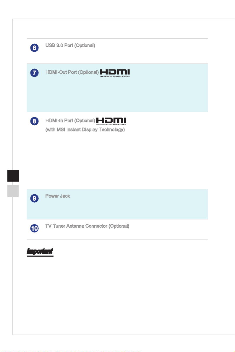
USB 3�0 Port (Optional)
®
®
6
The USB 3�0 port is backward-compatible with USB 2�0 devices� It supports up to 5Gbit/
s (SuperSpeed) data transfer rate�
HDMI-Out Port (Optional)
7
The High-Denition Multimedia Interface (HDMI) is an all-digital audio/video interface
capable of transmitting uncompressed streams� HDMI supports all TV format, including
standard, enhanced, or high-denition video, plus multi-channel digital audio on a single
cable�
* Please refer to the printed icon on the chassis for the exact position of HDMI-In Port
and HDMI-Out Port�
HDMI-In Port (Optional)
8
(with MSI Instant Display Technology)
The High-Denition Multimedia Interface (HDMI) is an all-digital audio/video interface
capable of transmitting uncompressed streams� HDMI supports all TV format, including
standard, enhanced, or high-denition video, plus multi-channel digital audio on a single
cable�
With MSI Instant Display Technology, when you connect power to the AIO PC
successfully, the monitor will automatically enter “standby” mode without pressing the
power button� When devices are connected to the HDMI-in port, the monitor will be
turned on immediately� You can also switch the modes through the Monitor Power /
Mode Button on the side panel if you have already turned on your AIO PC� This
technology helps to save more energy for your system�
Power Jack
9
The AC/DC adapter converts AC power to DC power for this jack� Power supplied
through this jack supplies power to the PC� To prevent damage to the PC, always use
the supplied power adapter�
TV Tuner Antenna Connector (Optional)
10
This connector is provided for digital TV tuner antenna�
Important
1� We suggest that you connect the AC/DC adapter to your AIO PC rst and then
connect the AC power cord to the socket-outlet for safety concerns�
2� High-speed devices are recommended for USB 3�0 ports whereas low-speed devices,
such as mouse or keyboard, are suggested to be plugged into the USB 2�0 ports on
the rear panel�
Page 17

Overview
1-91-8
Overview
Component Replacement & Upgrade
Please note that certain components preinstalled in the product may be upgradable or
replaceable by user’s request depending on the models users purchased�
1-91-8
For any further information on the product users purchased, please contact the local
dealer� Do not attempt to upgrade or replace any component of the product if you are
not an authorized dealer or service center, since it may cause the warranty void� It is
strongly recommended that you contact the authorized dealer or service center for any
upgrade or replace service�
Page 18

Page 19

2
Getting Started
This chapter provides you with the information on hardware setup procedures�
While connecting peripheral devices, be careful in holding the devices and use
a grounded wrist strap to avoid static electricity�
Page 20

2-2
38 -76 cm
15- 20
90- 120
Safety & Comfort Tips
The AIO PC is a portable platform that allows you to work anywhere� However, choosing
a good workspace is important if you have to work with your PC for a long period of
time�
1�
Your work area should have enough illumination�
Choose the proper desk and chair and adjust their height to t your posture when
2�
operating�
When sitting on the chair, sit straight and keep a good posture� Adjust the chair’s
3�
back (if available) to support your back comfortably�
Place you feet at and naturally on the oor, so that your knees and elbows have
4�
the proper position (about 90-degree) when operating�
Put your hands on the desk naturally to support your wrists�
5�
Adjust the angle/position of the AIO PC to have an optimal view�
6�
Avoid using your PC in a place where discomfort may occur (such as on the bed)�
7�
The AIO PC is an electrical device� Please treat it with great care to avoid personal
8�
injury�
1
3
6
4
5
4
2
2
4
Page 21

Getting Started
Hardware Setup
Important
The illustrations are for reference only� Your system may vary in appearance�
•
Please make sure the system has been grounded to earth through the AC power cord
•
and the electrical outlet before powering on the system�
Do not use any sharp objects on the display�
•
1� Adjust the stand to an appropriate angle until the system is securely positioned�
2-3
Page 22

2-4
1
2
3
2� Connect the adapter to the system and plug in the power cord�
3� Press the power button to power on the system�
Page 23

3
System Operations
This chapter provides you with essential information on system operations�
Important
All information is subject to change without prior notice�
Page 24

On-Screen Display (OSD)
The on-screen display (OSD) allows you to tune the viewing options of the monitor,
such as brightness, contrast, positioning, language, etc�
System Power
Menu/ Enter
Brightness/ Volume Down
1� Press the Menu button to launch the OSD main menu� Use the Up and Down buttons
to select the desired function menu and press the Menu button to enter� Use the
Up and Down buttons to select or tune the values to suit your personal preferences�
Monitor Power/ Mode
Brightness/ Volume Up
Brightness (function available under
Monitor mode): Adjusts overall screen
brightness�
Contrast: Adjusts dierence between
light and dark areas�
Page 25

System Operations
Information: Shows resolution, refresh
rate, and product details�
Factory Default: Resets monitor to
original settings�
After the settings are done, press the Mode button to exit�
Menu Language (function available
under Monitor mode): Changes
language of menu�
Scaling: Expands image to full screen�
3-33-2
Page 26

System Operations
3-53-4
2� Press the Up & Down buttons to adjust the system volume�
3� Press the Mode button to view the signal source� Press it again to select PC/ HDMI/
monitor o mode�
Important
Whenever any error takes place and incurs abnormal display or volume malfunction,
enter the OSD menu and reset your monitor to restore all settings to manufacturer
default for optimal performance�
Page 27

System Operations
3-53-4
System Operations
Power Management
Power management of personal computers (PCs) and monitors has the potential to
save signicant amounts of electricity as well as deliver environmental benets�
To be energy ecient, turn o your display or set your PC to sleep mode after a period
of user inactivity�
Power Management in Windows 7
[Power Options] in Windows OS allow you to control the power management
■
features of your display, hard drive, and battery� Go to [Start] > [Control Panel]
> [System and Security]�
Then click on the [Power Options] link�
Select a power plan that suits your personal needs� You may also ne-tune the
settings by clicking [Change plan settings]�
The Shut Down Computer menu presents the options of Sleep (S3/S4) & Shut
■
Down (S5) for rapid and easy management of your system power�
Power Management in Windows 8.x
[Power Options] in Windows OS allow you to control the power management
■
features of your display, hard drive, and battery� Go to [Start] > [Control Panel]
> [System and Security]�
Then click on the [Power Options] link�
Select a power plan that suits your personal needs� You may also ne-tune the
settings by clicking [Change plan settings]�
3-53-4
Page 28

System Operations
3-73-6
The Shut Down Computer menu presents the options of Sleep (S3/S4) & Shut
■
Down (S5) for rapid and easy management of your system power�
Power Management through ENERGY STAR
qualied monitors
The power management feature allows the computer to initiate a
low-power or “Sleep” mode after a period of user inactivity� When
used with an external ENERGY STAR qualied monitor, this feature
also supports similar power management features of the monitor�
To take advantage of these potential energy savings, the power
management feature has been preset to behave in the following ways when the system
is operating on AC power:
Turn o the display after 15 minutes
■
Initiate Sleep after 30 minutes
■
Waking the System Up
The computer shall be able to wake up from power saving mode in response to a
command from any of the following:
the power button,
■
the network (Wake On LAN),
■
the mouse,
■
the keyboard�
■
Energy Saving Tips:
Turn o the monitor by pressing the monitor power button after a period of user
■
inactivity�
Tune the settings in Power Options under Windows OS to optimize your PC’s
■
power management�
Install power saving software to manage your PC’s energy consumption�
■
Always disconnect the AC power cord or switch the wall socket o if your PC
■
would be left unused for a certain time to achieve zero energy consumption�
Page 29

System Operations
3-73-6
System Operations
Network Connection (Windows 7)
Wired LAN
1� Go to [Start] > [Control Panel]�
2� Select [Connect to the Internet] under [Network and Internet]�
3-73-6
3� Select [Broadband (PPPoE)] to connect using DSL or cable that requires a user
name and password�
4� Type the information from your Internet Service Provider (ISP) and click [Connect] to
establish your LAN connection�
Page 30

System Operations
3-93-8
Wireless LAN
1� Go to [Start] > [Control Panel]�
2� Select [Connect to the Internet] under [Network and Internet]�
3� Select [Wireless] to connect using a wireless router or a wireless network�
4� A list of available WLAN connections pops up� Choose a connection from the list or
click [Open Network and Sharing Center] to establish a new connection�
Page 31

System Operations
3-93-8
System Operations
5� To establish a new WLAN connection, select [Set up a new connection or network] in
[Network and Sharing Center]�
6� Followingly, choose [Manually connect to a wireless network] and click [Next] to
continue�
3-93-8
7� Enter information for the wireless network you intend to add and click [Next] to
proceed�
8� A new WLAN connection has been made� Click [Close] to exit or select [Change
connection settings] to modify the WLAN settings�
Page 32

System Operations
3-113-10
Network Connection (Windows 8.x)
Wired LAN
1� Go to [Start] > [Control Panel]�
2� Select [View network status and tasks] under [Network and Internet]�
3� To establish a new connection, select [Network and Sharing Center]�
4� Select [Set up a new connection or network]�
Page 33

System Operations
3-113-10
System Operations
5� Choose [Connect to the Internet]�
6� Select [Broadband (PPPoE)] to connect using DSL or cable that requires a user
name and password�
7� Type the information from your Internet Service Provider (ISP) and click [Connect] to
establish your LAN connection�
3-113-10
Page 34

System Operations
3-133-12
Wireless LAN
1� Select [Settings] on Desktop, locate a wireless icon with available network�
2� A list of available WLAN connections pops up� Choose a connection from the list�
3� To establish a new connection, select [Network and Sharing Center] under [Network
and Internet] in [Control Panel]�
4� Select [Set up a new connection or network]�
5� Followingly, choose [Manually connect to a wireless network] and click [Next] to
continue�
6� Enter information for the wireless network you intend to add and click [Next] to
proceed�
7� A new WLAN connection has been made� Click [Close] to exit or select [Change
connection settings] to modify the WLAN settings�
Page 35

System Operations
3-133-12
System Operations
System Recovery (Windows 7)
Important
The Recovery Tool is only available on systems bundled with Windows OS and MSI
utilities by default�
The purposes for using the Recovery Tool may include:
Restore the system back to the initial status of original manufacturer’s default
■
settings�
When some errors have occurred to the operating system in use�
■
When the operating system is aected by virus and is not able to work
■
normally�
When you want to install the OS with other built-in languages�
■
Before using the Recovery Tool, please back up the important data saved on your
system drive to other storage devices�
If the following solution fails to recover your system, please contact the authorized local
distributor or service center for further assistance�
Recovering the System with the F3 Hotkey
If the system encounters non-recoverable problems, it is always recommended that
you try the F3 hotkey to recover your system with the recovery partition of the hard disk
drive rst�
3-133-12
Follow the instructions below to continue:
1� Restart the system�
2� Press the F3 hotkey on the keyboard when the following image appears�
Page 36

System Operations
3-153-14
3� Enter the Recovery Tool� This tool contains three features: Backup System, Restore
System and Recover to factory default�
System Backup
It is highly recommended that users back up the system as the solution in the event of
a catastrophic disk failure or other accidents�
Follow the instructions below to continue:
1� Select [Backup System] to enter� Alternatively, select [X] or press [Esc] on the
keyboard to exit�
Page 37

System Operations
3-153-14
System Operations
2� Select [BACKUP] to start the system backup immediately�
The Initial Backup
The initial backup may take a while� Please let it complete without interruption�
Subsequent Backups
Subsequent backups will replace the previous backup les�
3-153-14
Page 38

System Operations
3-173-16
3� The system backup is in progress� Please note that it may take a while� Do not switch
o the power, or it may cause unknown damage to the system�
4� Alternatively, select [CANCEL] to stop the system backup immediately� Please do not
switch o the power while the system backup cancellation is in progress�
Page 39

System Operations
3-173-16
System Operations
5� The following message indicates a successful system backup� Press [OK] to nish�
System Restore
This tool helps to return the system to a previous state with the backup les that users
created and saved in the hard disk drive beforehand� If no backup les are available, the
system will be restored to the default setup�
Follow the instructions below to continue:
1� Select [Restore System] to enter� Alternatively, select [X] or press [Esc] on the
keyboard to exit�
3-173-16
Page 40

System Operations
3-193-18
2� Select [OK] or [NEXT] so that the system can recover to the previous backup or default
setup� Alternatively, select [CANCEL] to stop the system restore immediately�
With backup les: restoring the system to the previous backup
Without backup les: restoring the system to the default setup
Page 41

System Operations
3-193-18
System Operations
3� The system restore is in progress� Please note that it may take a while� Do not switch
o the power, or it may cause unknown damage to the system�
4� The following message indicates a successful system restore� Press [OK] to nish�
Restart the system and access the Windows operating system as usual� If the restore
process fails or is interrupted, please start the whole procedure all over again�
3-193-18
Page 42

System Operations
3-213-20
System Recovery
This tool helps to recover the system back to factory default settings� All data on the
HDD will be erased while all settings will be restored to factory default�
Follow the instructions below to continue:
1� Select [Recover to factory default] to enter� Alternatively, select [X] or press [Esc] on
the keyboard to exit�
2� The system will be recovered to factory settings� All data will be gone� Make sure all
important data have been backed up� Select [NEXT] to continue� Alternatively, select
[CANCEL] to stop�
Page 43

System Operations
3-213-20
System Operations
3� Please select [OK] so that the system can recover its default setup�
4� The system recovery is in progress� Please note that it may take a while� Do not
switch o the power, or it may cause unknown damage to the system�
3-213-20
Page 44

System Operations
3-233-22
5� The following message indicates a successful system recovery� Press [OK] to
nish� Restart the system and access the Windows operating system as usual� If
the recovery process fails or is interrupted, please start the whole procedure all
over again�
Page 45

System Operations
3-233-22
System Operations
System Recovery (Windows 8.x)
Important
The System Recovery Function is only available on systems bundled with Windows OS
and MSI utilities by default�
The purposes for using the System Recovery Function may include:
Restore the system back to the initial status of original manufacturer’s default
■
settings�
When some errors have occurred to the operating system in use�
■
When the operating system is aected by virus and is not able to work
■
normally�
When you want to install the OS with other built-in languages�
■
Before using the System Recovery Function, please back up the important data saved
on your system drive to other storage devices�
If the following solution fails to recover your system, please contact the authorized local
distributor or service center for further assistance�
3-233-22
Page 46

System Operations
3-253-24
Recovery from the Operating System
Refresh PC
The Refresh PC utility checks whether the system les, Windows registry, and other
important system components are working ne or not; on nding issues with Windows
les, it will attempt to repair your PC� If your PC isn’t running well, you can refresh it
without losing your personal les�
1� Click [Settings]
recovery]�
2� Click [Recovery] > [Refresh your PC without aecting your les], and select [Get
started]�
3� It will show the changes which will be made during the process, click [Next] to
continue�
on desktop, then select [Change PC settings] > [Update and
Page 47

System Operations
3-253-24
System Operations
4� A message indicates that your PC is ready to be refreshed, click [Refresh] to start�
This might take a while�
5� After the refresh process ends, you will be back to Windows Start Screen where
you can nd all default Windows utilities and widgets�
3-253-24
Page 48

System Operations
3-273-26
Reset PC
The Reset utility will bring the system back to original factory settings�
1� Click [Settings]
recovery]�
2� Click [Recovery] > [Remove everything and reinstall Windows], and select [Get
started]�
3� It will show the changes to be made during the process, click [Next] to continue�
on desktop, then select [Change PC settings] > [Update and
Page 49

System Operations
3-273-26
System Operations
4� You will be prompted to choose which drive you want to clean for a hard disk with
multiple partitions�
5� Now, select either to remove les or to fully clean drives according to your needs�
3-273-26
6� It is now ready to reset your PC, click [Reset] and follow the on-screen instructions
to restart your PC�
Page 50

Page 51

Troubleshooting
A
Page 52

Troubleshooting
A-3A-2
My system does not start�
1� Check if the system is connected to an electrical outlet and it is turned on�
2� Check if the power cord and all cables are connected rmly�
When I turn on my computer, the message “Operating System not found”
appears or Windows does not start�
1� Check if there is a non-bootable CD/ DVD inside the optical disk drive� If so,
remove the CD/ DVD then restart the computer�
2� Check Boot Device Priority settings in the BIOS Setup�
The system can not be shut down�
It is best to shut down your computer using the Shut Down icon in the operating
system� Using other methods, including those listed below, may result in data failure�
If the Shut Down procedure does not work, choose one of the following steps:
1� Press Ctrl+Alt+Del keys, then choose Shut Down�
2� Press and hold the power button till the system is o�
3� Unplug the power cable from the system�
My microphone does not work�
1� For built-in microphone, please go to Start > Control Panel > Sounds and Audio
Devices > Audio to check if it is muted�
2� If you are using an external microphone, check that the microphone is plugged
into the Microphone jack�
The Internet connection has problems�
1� If you are having a problem connecting to your Internet Service Provider (ISP),
check if the ISP is experiencing technical problems�
2� Check the Network settings and connection and make sure the system is properly
congured to Internet access�
3� The wireless LAN data transfer speed is aected by distance and obstructions
between devices and access points� To maximize the data transfer speed, choose
the access point closest to your system�
Page 53

Troubleshooting
A-3A-2
Troubleshooting
System speakers do not work�
1� Check the master volume setting in the Audio Mixer�
2� If you are using an application that has its own volume control, check if the volume
is muted�
3� If you have connected an audio cable to the Headphone jack, disconnect it�
4� If the system has OSD function, please adjust the volume of OSD�
I cannot play a CD/ DVD with the DVD-ROM of the system�
1� Make sure the label of the CD/ DVD is facing up�
2� If the CD/ DVD requires software, make sure the software is well installed
according to the program instructions�
3� If a region code warning appears when you play the DVD, the problem could be
that the DVD is incompatible with the DVD-ROM in your system� The region code
is listed on the disc packaging�
4� If you see video but cannot hear audio, check the media player� Also, make sure
the speakers and the master volume setting in the Audio Mixer are not muted�
5� Check if the drivers are installed properly� Click Start > Control Panel > System >
Device Manager�
6� A dirty or scratched disc may cause the computer to hang when it is trying to read
the disc� If necessary, reboot the computer, remove the disc, and check if it is
dirty or scratched�
7� Please use DVD player software like PowerDVD or WinDVD to play DVD video�
A-3A-2
My DVD-ROM drive tray does not open�
1� Make sure the computer is turned on�
2� Press the Eject button on the DVD-ROM drive�
3� If the Eject button does not work, open the tray by inserting a sharp, pointed object
into the hole next to the Eject button�
System monitor does not display anything�
1� Check if the system is connected to an electrical outlet and it is turned on�
2� The system may be in Standby mode� Press any key to activate the Display�
 Loading...