

Page 1
915P Neo3 / 915G Neo3
MS-7166 (v1.X ATX Mainboard)
G52-M7166X1
i
Page 2
Manual Rev: 1.0
Release Date: MAY. 2005
FCC-B Radio Frequency Interference Statement
This equipment has been tested and found to comply with the limits for a class B
digital device, pursuant to part 15 of the FCC rules. These limits are designed to
provide reasonable protection against harmful interference when the equipment is
operated in a commercial environment. This equipment generates, uses and can
radiate radio frequency energy and, if not installed and used in accordance with the
instruction manual, may cause harmful interference to radio communications. Operation
of this equipment in a residential area is likely to cause harmful interference, in which
case the user will be required to correct the interference at his own expense.
Notice 1
The changes or modifications not expressly approved by the party responsible for
compliance could void the user’s authority to operate the equipment.
Notice 2
Shielded interface cables and A.C. power cord, if any, must be used in order to
comply with the emission limits.
VOIR LA NOTICE D’INSTALLATION AVANT DE RACCORDER AU RESEAU.
Micro-Star International
MS-7166
This device complies with Part 15 of the FCC Rules. Operation is subject to the
following two conditions:
(1) this device may not cause harmful interference, and
(2) this device must accept any interference received, including interference that
may cause undesired operation
ii
Page 3

Copyright Notice
The material in this document is the intellectual property of MICRO-STAR
INTERNATIONAL. We take every care in the preparation of this document, but no
guarantee is given as to the correctness of its contents. Our products are under
continual improvement and we reserve the right to make changes without notice.
Trademarks
All trademarks are the properties of their respective owners.
AMD, Athlon™, Athlon™ XP, Thoroughbred™, and Duron™ are registered trademarks of AMD Corporation.
Intel® and Pentium® are registered trademarks of Intel Corporation.
PS/2 and OS®/2 are registered trademarks of International Business Machines
Corporation.
Microsoft is a registered trademark of Microsoft Corporation. Windows® 98/2000/NT/
XP are registered trademarks of Microsoft Corporation.
NVIDIA, the NVIDIA logo, DualNet, and nForce are registered trademarks or trademarks of NVIDIA Corporation in the United States and/or other countries.
Netware® is a registered trademark of Novell, Inc.
Award® is a registered trademark of Phoenix Technologies Ltd.
AMI® is a registered trademark of American Megatrends Inc.
Kensington and MicroSaver are registered trademarks of the Kensington Technology
Group.
PCMCIA and CardBus are registered trademarks of the Personal Computer Memory
Card International Association.
Technical Support
If a problem arises with your system and no solution can be obtained from the user’s
manual, please contact your place of purchase or local distributor. Alternatively,
please try the following help resources for further guidance.
† Visit the MSI homepage & FAQ site for technical guide, BIOS updates, driver
updates, and other information: http://www.msi.com.tw
com.tw/program/service/faq/faq/esc_faq_list.php
† Contact our technical staff at: support@msi.com.tw
Revision History
Revision Revision History Date
V1.0 First release for PCB 1.X May. 2005
& http://www.msi.
with Intel 915P/915G & ICH6R/ ICH6
iii
Page 4
Safety Instructions
1. Always read the safety instructions carefully.
2. Keep this User’s Manual for future reference.
3. Keep this equipment away from humidity.
4. Lay this equipment on a reliable flat surface before setting it up.
5. The openings on the enclosure are for air convection hence protects the equip-
ment from overheating. Do not cover the openings.
6. Make sure the voltage of the power source and adjust properly 110/220V before connecting the equipment to the power inlet.
7. Place the power cord such a way that people can not step on it. Do not place
anything over the power cord.
8. Always Unplug the Power Cord before inserting any add-on card or module.
9. All cautions and warnings on the equipment should be noted.
10. Never pour any liquid into the opening that could damage or cause electrical
shock.
11. If any of the following situations arises, get the equipment checked by a service
personnel:
† The power cord or plug is damaged.
† Liquid has penetrated into the equipment.
† The equipment has been exposed to moisture.
† The equipment has not work well or you can not get it work according to
User’s Manual.
† The equipment has dropped and damaged.
† The equipment has obvious sign of breakage.
12. Do not leave this equipment in an environment unconditioned, storage
temperature above 600 C (1400F), it may damage the equipment.
CAUTION: Danger of explosion if battery is incorrectly replaced.
Replace only with the same or equivalent type recommended by the
manufacturer.
To protect the global environment and as an environmentalist, MSI
must remind you that...
Under the European Union ("EU") Directive on Waste Electrical and
Electronic Equipment, Directive 2002/96/EC, which takes effect on
August 13, 2005, products of "electrical and electronic equipment"
cannot be discarded as municipal waste anymore and manufac-
turers of covered electronic equipment will be obligated to take
back such products at the end of their useful life. MSI will comply with the product
take back requirements at the end of life of MSI-branded products that are sold into
the EU. You can return these products to local collection points.
iv
Page 5

CONTENTS
Chapter 1. Getting Started....................................................................................1-1
Mainboard Specifications...................................................................................1-2
Mainboard Layout................................................................................................1-4
Packing Contents.................................................................................................1-5
Chapter 2. Hardware Setup..................................................................................2-1
Quick Components Guide...................................................................................2-2
Central Processing Unit: CPU.............................................................................2-3
Introduction to LGA 775 CPU......................................................................2-3
CPU & Cooler Installation.............................................................................2-4
Memory.................................................................................................................2-7
Introduction to DDR SDRAM.......................................................................2-7
DIMM Module Combination...........................................................................2-7
Memory Module Population Rules...............................................................2-8
Installing DDR Modules................................................................................2-8
Power Supply......................................................................................................2-9
ATX 24-Pin Power Connector: ATX1.........................................................2-9
ATX 12V Power Connector: JPW1............................................................2-9
Back Panel.........................................................................................................2-10
Mouse/Keyboard Connector....................................................................2-10
VGA Connector (Optional, for 915G only)..............................................2-10
Serial Port Connector: COM Port...............................................................2-11
USB Connectors.........................................................................................2-11
LAN (RJ-45) Jack......................................................................................2-12
Audio Port Connectors..............................................................................2-12
Parallel Port Connector: LPT1...................................................................2-13
Floppy Disk Drive Connector: FDD1.........................................................2-14
Fan Power Connectors: CPUFAN1/NBFAN1/SYSFAN1/PWRFAN1.......2-14
Connectors........................................................................................................2-14
Hard Disk Connector: IDE1, IDE2, IDE3....................................................2-15
FWH/LPC Debugging Pin Header: JLPC1.................................................2-15
Serial ATA Connectors controlled by Intel ICH6: SATA1~SATA4...........2-16
CD-In Connector: JCD1.............................................................................2-17
Front Panel Connectors: JFP1 / JFP2......................................................2-17
Front USB Connectors: JUSB1 / JUSB2..................................................2-18
Front Panel Audio Connector: JAUD1......................................................2-18
IrDA Infrared Module Header: JIR1...........................................................2-19
IEEE 1394 Connector: J1394_1/J1394_2 (Optional)...............................2-19
v
Page 6

D-Bracket™ 2 Connector: JDB1..............................................................2-20
Jumpers..............................................................................................................2-23
Chassis Intrusion Switch Connector: JCI1..............................................2-23
Clear CMOS Jumper: JBAT1.....................................................................2-23
Slots....................................................................................................................2-24
PCI Express Slots (optional).....................................................................2-24
PCI (Peripheral Component Interconnect) Slots......................................2-25
PCI Interrupt Request Routing...................................................................2-25
Chapter 3. BIOS Setup............................................................................................3-1
Entering Setup.....................................................................................................3-2
Control Keys................................................................................................3-2
Getting Help..................................................................................................3-2
Main Menu....................................................................................................3-2
Default Settings...........................................................................................3-2
The Main Menu.....................................................................................................3-3
Standard CMOS Features...................................................................................3-5
Advanced BIOS Features...................................................................................3-7
Advanced Chipset Features............................................................................3-10
Integrated Peripherals.......................................................................................3-12
Power Management Features..........................................................................3-16
PNP/PCI Configurations.....................................................................................3-19
H/W Monitor........................................................................................................3-20
Frequency/Voltage Control...............................................................................3-22
Load BIOS Defaults...........................................................................................3-25
Set Supervisor/ User Password......................................................................3-26
Chapter 4. Introduction to DigiCell.....................................................................4-1
Introduction:.........................................................................................................4-2
H/W Diagnostic....................................................................................................4-4
Communication.....................................................................................................4-5
Software Access Point.......................................................................................4-6
Terminology..................................................................................................4-6
Access Point Mode.....................................................................................4-7
WLAN Card Mode........................................................................................4-8
Live Update..........................................................................................................4-9
MEGA STICK.......................................................................................................4-10
vi
Page 7

Basic Function...........................................................................................4-10
Non-Unicode programs supported...........................................................4-12
Core Center (for Pentium 4 CPU).....................................................................4-14
Left-wing: Current system status............................................................4-15
Right-wing: PC hardware status during real time operation.................4-15
Audio Speaker Setting......................................................................................4-16
Power on Agent.................................................................................................4-18
Power On...................................................................................................4-18
Power Off / Restart...................................................................................4-19
Start With....................................................................................................4-19
Auto Login..................................................................................................4-20
Chapter 5. Introduction to Intel ICH6R SATA RAID..........................................5-1
BIOS Configuration..............................................................................................5-2
Using the Intel RAID Option ROM................................................................5-2
Installing Software..............................................................................................5-8
Install Driver in Windows XP / 2000...........................................................5-8
Installation of Intel Application Accelerator RAID Edition..........................5-9
RAID Migration Instructions..............................................................................5-14
Create RAID Volume from Existing Disk...................................................5-15
Chapter 6. VIA VT6410 IDE RAID...........................................................................6-1
Introduction..........................................................................................................6-2
RAID 0 (Striping)..........................................................................................6-2
RAID Basics.................................................................................................6-2
RAID 1 (Mirroring)........................................................................................6-3
RAID 0+1 (Striping/Mirroring)......................................................................6-3
BIOS Configuration..............................................................................................6-4
Create Disk Array........................................................................................6-5
Delete Disk Array.........................................................................................6-8
Create and Delete Spare Hard Drive.........................................................6-9
Select Boot Array......................................................................................6-10
View Serial Number of Hard Drive...........................................................6-10
Duplicate Critical RAID 1 Array..................................................................6-11
Rebuild Broken RAID 1/0+1 Array............................................................6-12
Installing Software............................................................................................6-14
Install Driver in Windows XP/2000...........................................................6-14
vii
Page 8

Installation of VIA IDE RAID Utility.............................................................6-15
Using VIA RAID Tool..........................................................................................6-18
Chapter 7. Itroduction to Realtek ALC880........................................................7-1
Installing the Realtek HD Audio Driver................................................................7-3
Installation for Windows 2000/XP..............................................................7-3
Software Configuration......................................................................................7-5
Sound Effect................................................................................................7-5
Mixer.............................................................................................................7-9
Microphone................................................................................................7-19
3D Audio Demo...........................................................................................7-19
Using 2-, 4-, 6- & 8- Channel Audio Function.................................................7-22
viii
Page 9

Getting Started
Chapter 1. Getting
Started
Getting Started
Thank you for choosing the 915P Neo3 / 915G Neo3 (MS-
7166) v1.x ATX mainboard. The 915P Neo3 / 915G Neo3 mainboard
is based on Intel® 915P / 915G and Intel® ICH6R / ICH6 chipset for
optimal system efficiency. Designed to fit the advanced Intel
Pentium 4 Prescott LGA775 processor, the 915P Neo3 / 915G
Neo3 mainboard delivers a high performance and professional desk-
top platform solution.
®
1-1
Page 10

MS-7166 ATX Mainboard
Mainboard Specifications
CPU
† Supports Intel® Pentium 4/ Celeron D Prescott LGA775 processors in LGA775
package.
† Supports 2004 Performance FMB CPU VR Design.
† Supports 3/4 pin CPU Fan Pin-Header with Fan Speed Control.
† Supports up to Pentium 4 3XX, 5XX, 6XX & P4EE (Intel Pentium 4 Processor with
HT Technology Extreme Edition).
(For the latest information about CPU, please visit http://www.msi.com.tw/program/
products/mainboard/mbd/pro_mbd_cpu_support.php)
Chipset
† Intel® 915P / 915G chipset
- Supports FSB 533/ 800MHz.
- Supports PCI Express x16 graphics interface.
- Supports DDR333/400
- Integrated graphics controller.
† Intel® ICH6R/ ICH6 chipset
- Hi-Speed USB (USB2.0) controller, 480Mb/sec, up to 8 ports.
- 4 Serial ATA ports with transfer rate up to 1.5Gb/s.
- 1 channel Ultra ATA 100 bus Master IDE controller.
- PCI Master v2.3, I/O APIC.
- ACPI 2.0 Compliant.
- Serial ATA 150 RAID 0, RAID 1 and Matrix RAID (for ICH6R only).
- Integrated AHCI controller (for ICH6R only).
Main Memory
† Supports four unbuffered DIMM of 2.5 Volt DDR SDRAM
† Supports up to 4GB memory size.
† Supports Dual channel DDR memory architecture.
† Supports DDR 333/400 memory interface.
(For the updated supporting memory modules, please visit http://www.msi.com.tw/
program/products/mainboard/mbd/pro_mbd_trp_list.php.)
Slots
† One PCI Express x16 slot (supports PCI Express Bus specification v1.0a compliant).
† One PCI Express x1 slot.
† Three 32-bit v2.3 Master PCI bus slots (support 3.3v/5v PCI bus interface).
On-Board IDE
† One Ultra DMA 66/100 IDE controllers integrated in ICH6R/ ICH6 and VIA 6410.
- Supports PIO, Bus Master operation modes.
- Can connect up to Six Ultra ATA drives.
1-2
Page 11

Getting Started
† Serial ATA 150 controller integrated in ICH6R/ICH6.
- Up to 150MB/sec transfer speed.
- Can connect up to four Serial ATA devices.
- Supports AHCI controller with SATA Raid 0, Raid 1 and Matrix Raid (ICH6R).
† VIA 6410, chipest.
- Supports Raid 0, Raid 1, Raid 0+1 and JBOD.
On-Board Peripherals
† On-Board Peripherals include:
- 1 floppy port supports 1 FDD with 360K, 720K, 1.2M, 1.44M and 2.88Mbytes
- 1 serial port
- 1 VGA port (915G)
- 1 parallel port supports SPP/EPP/ECP mode
- 1 Line-In / Line-Out / MIC-In / Rear Speaker Out / Center-Subwoofer Speaker Out/
SPDIF-Out
- 8 USB ports (Rear * 4/ Front * 4)
- 1 RJ-45 LAN jack (optional)
LAN
† Realtek RTL 8100C / 8110S
- Supports 10/ 100 Mb/s or 1000 Mb/s.
- Compliane with PCI 2.2.
- Supports ACPI Power Management.
1394 (optional)
† Supports two IEEE1394 onboard pinheader. Transfer rate is up to 400 Mbps.
† Controlled by VIA VT6307 chip.
Audio
† High Definition link controller integrated in Intel® ICH6R/ICH6 chip.
† 8-channel audio codec Realtek ALC880.
- Compliant with Azalia 1.0 Spec.
BIOS
† The mainboard BIOS provides “Plug & Play” BIOS which detects the peripheral
devices and expansion cards of the board automatically.
† The mainboard provides a Desktop Management Interface (DMI) function which
records your mainboard specifications.
Mounting and Dimension
† ATX Form Factor: 29.5 cm x 24.5 cm
† 9 mounting holes
1-3
Page 12
MS-7166 ATX Mainboard
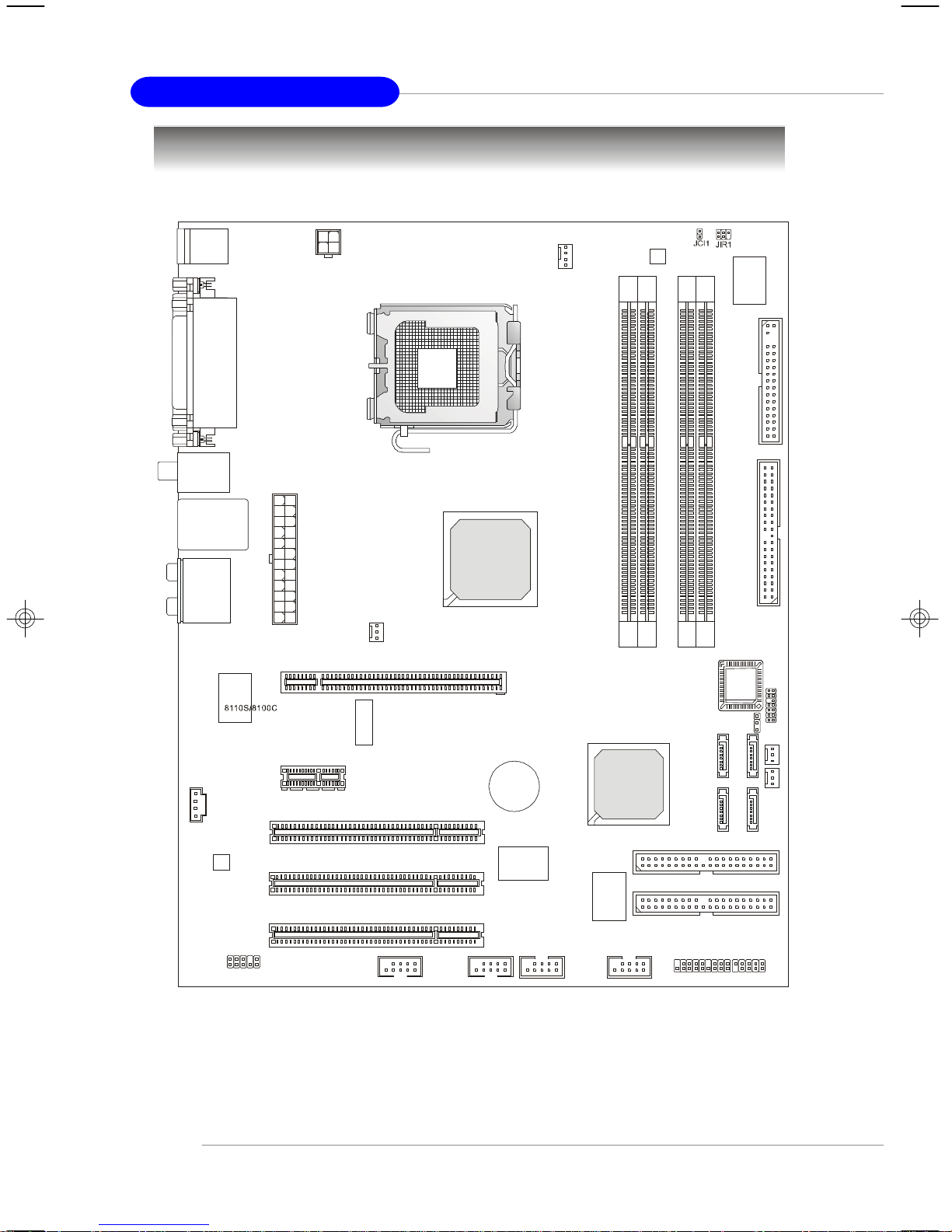
PCI1
PCI2
PCI3
F
D
D1IDE
1
BIOS
BATT
Intel 915P/915G
Intel ICH6R/ICH6
PCI_E2
Mainboard Layout
Top : mouse
Bottom: keyboard
Top :
Parallel Port
Bottom:
COM port
VGA port(915G only)
USB
ports
Top: LAN Jack
Bottom: USB ports
T:
Line-In
M:
Line-Out
B:
Mic
T:RS-Out
M:CS-Out
B:SPDIFOut
1
D
C
J
0
8
8
C
L
A
JPW1
1
X
T
A
PCI _E1
CPUFAN1
1
N
A
F
B
N
0
8
4
2
6
8
M
T
R
+
VT6307
1
M
M
I
D
VT6410
2
M
M
I
D
3
4
M
M
M
M
I
I
D
D
1
C
P
L
J
1
T
A
B
1
J
4
A
T
A
S
2
A
T
A
S
N
3
A
A
F
T
R
A
W
S
P
1
N
A
F
S
Y
S
1
A
T
A
S
IDE2
JAUD1
915P Neo3 / 915G Neo3 (MS-7166) v1.x ATX Mainboard
1-4
J1394_1(optional)J1394_2(optional)
JUSB1 JUSB2
JDB1
JFP2
IDE3
JFP1
Page 13
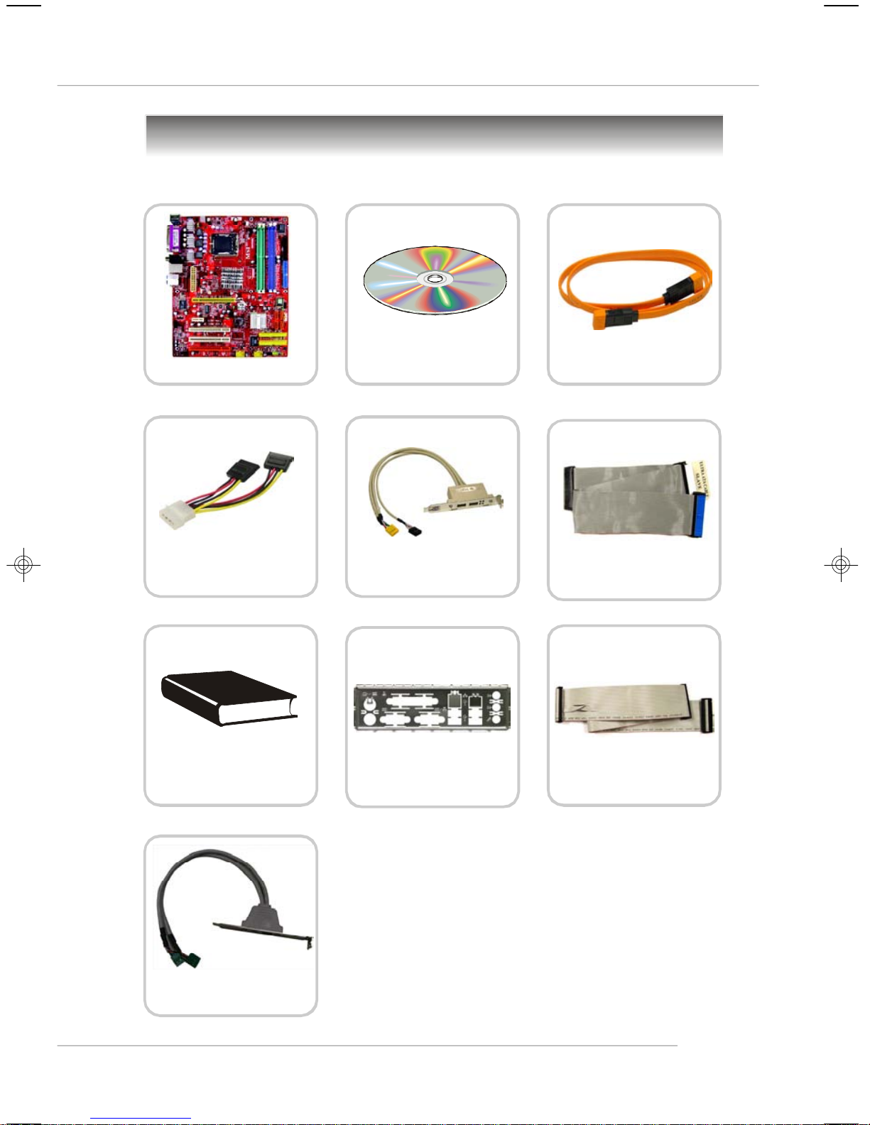
Packing Contents
Getting Started
MSI motherboard
Power Cable
User’s Guide
MSI Driver/Utility CD
D-Bracket 2
(Optional)
Back IO Shield
SATA Cable
Standard Cable for
IDE Devices
Standard Cable for
Floppy Disk
IEEE1394 Bracket
(Optional)
* The pictures are for reference only and may vary
from the packing contents of the product you
purchased.
1-5
Page 14

Hardware Setup
Chapter 2. Hardware Setup
Hardware Setup
This chapter tells you how to install the CPU, memory modules,
and expansion cards, as well as how to setup the jumpers on the
mainboard. Also, it provides the instructions on connecting the peripheral devices, such as the mouse, keyboard, etc.
While doing the installation, be careful in holding the components and follow the installation procedures.
2-1
Page 15
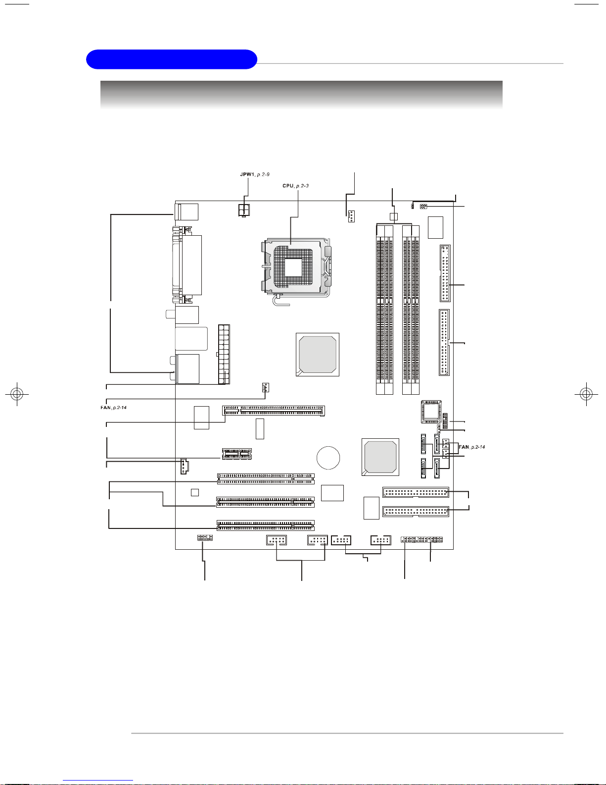
MS-7166 ATX Mainboard
JIR1,
p.2-19
SATA1~4
JLPC1
p.2-15
JBAT1
p.2-23
CPUFAN1
,
p.2-14
DIMM1~4
IDE2/IDE3
JFP1/JFP2
JUSB1/JUSB2
J1394_1/J1394_2
Quick Components Guide
Back Panel I/O, p.2-10
ATX1, p.2-9
PCIE, p.2-24
JCD1, p.2-17
, p.2-7
JCI1, p.2-23
FDD1, p.2-14
IDE1, p.2-15
,
,
, p.2-16
PCI1~3, p.2-25
JAUD1, p.2-18
2-2
, p.2-19
, p.2-18
, p.2-15
, p.2-17
JDB1, p.2-20
Page 16
Hardware Setup
Central Processing Unit: CPU
The mainboard supports Intel® Pentium 4 Prescott processor. The mainboard
uses a CPU socket called LGA775. When you are installing the CPU, make sure to
install the cooler to prevent overheating. If you do not have the CPU cooler,
contact your dealer to purchase and install them before turning on the computer.
For the latest information about CPU, please visit http://www.msi.com.tw/
program/products/mainboard/mbd/pro_mbd_cpu_support.php.
MSI Reminds You...
Overheating
Overheating will seriously damage the CPU and system, always make
sure the cooling fan can work properly to protect the CPU from
overheating.
Replacing the CPU
While replacing the CPU, always turn off the ATX power supply or
unplug the power supply’s power cord from grounded outlet first to
ensure the safety of CPU.
Overclocking
This motherboard is designed to support overclocking. However, please
make sure your components are able to tolerate such abnormal setting,
while doing overclocking. Any attempt to operate beyond product specifications is not recommended. We do not guarantee the damages
or risks caused by inadequate operation or beyond product
specifications.
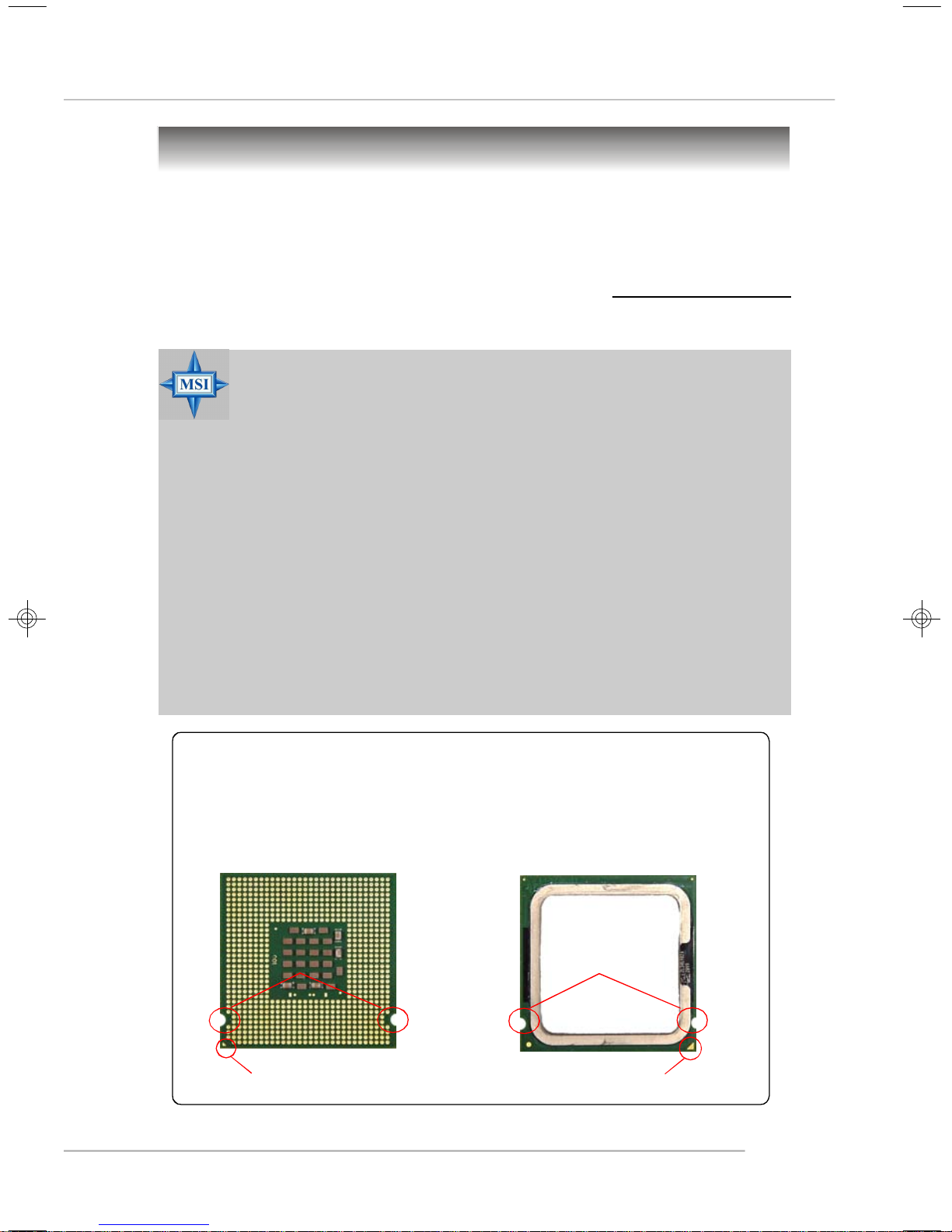
Introduction to LGA 775 CPU
The pin-pad side of LGA 775
CPU.
Alignment Key Alignment Key
The surface of LGA 775 CPU.
Remember to apply some silicone heat transfer compound on
it for better heat dispersion.
Yellow triangle is the Pin 1 indicator
Yellow triangle is the Pin 1 indicator
2-3
Page 17
MS-7166 ATX Mainboard
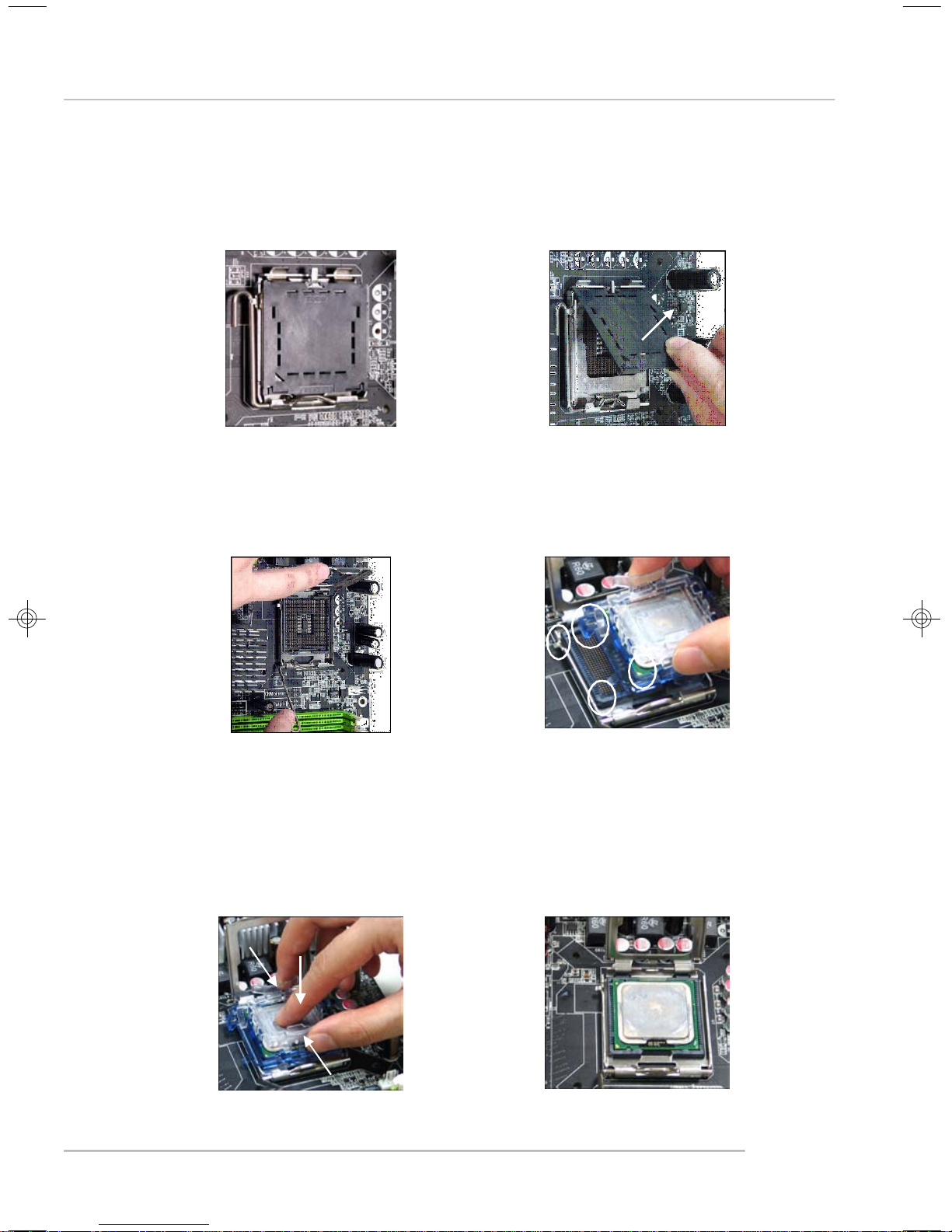
CPU & Cooler Installation
When you are installing the CPU, make sure the CPU has a cooler at-
tached on the top to prevent overheating. If you do not have the cooler, contact
your dealer to purchase and install them before turning on the computer. Meanwhile,
do not forget to apply some silicon heat transfer compound on CPU before installing
the heat sink/cooler fan for better heat dispersion.
Follow the steps below to install the CPU & cooler correctly. Wrong installation
will cause the damage of your CPU & mainboard.
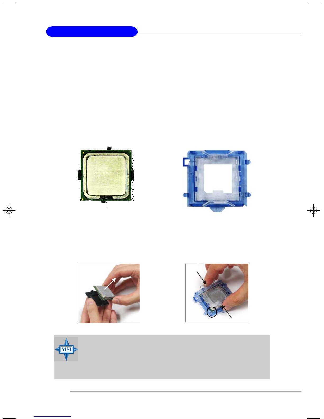
1.The CPU has a land side cover on the
bottom to protect the CPU contact from
damage. Rotate it to make the pin 1
indicator (yellow triangle) in the rightbottom corner.
land side cover
3.Use 2 hands to remove the land side
cover (if any). Please note not to touch
the pins.
2.Take out the accompanying CPU Clip
and rotate it for the same direction
as the CPU (Pin 1 indicator is in the
left-bottom corner).
4.Align the two pin 1 indicators (the
triangles on the CPU & the CPU Clip),
and use the CPU Clip to clip the CPU
up, pressing the clips on both sides
to the center, as the arrows shown.
MSI Reminds You...
1.Confirm if your CPU cooler is firmly installed before turning on your
system.
2.Do not touch the CPU socket pins to avoid damaging.
3. The availability of the CPU land side cover depends on your CPU
packing.
2-4
Page 18
Hardware Setup
5.The CPU has a plastic cap on it to
protect the contact from damage.
Before you have installed the CPU,
always cover it to protect the socket
pin.
7.Lift the load lever up and open the
load plate.
6.Remove the cap from lever hinge side
(as the arrow shows). The pins of
socket reveal.
8.Correctly align the triangle of CPU Clip
with the CPU chamfer, and the square
on the CPU Clip to the hook of the
socket.
9.Use your thumb and the middle fingers to push the clips to release the
CPU, then press down the CPU with
your index finger to allow the whole
module to be installed onto the CPU
socket.
10.The CPU is installed well on the CPU
socket.
2-5
Page 19

MS-7166 ATX Mainboard
11.Visually inspect if the CPU is seated
well into the socket, then remove the
CPU Clip with 2 fingers. Then cover
the load plate onto the package.
13. Align the holes on the mainboard with
the cooler. Push down the cooler until
its four clips get wedged into the
holes of the mainboard.
12. Press down the load lever lightly
onto the load plate, and then secure
the lever with the hook under retention tab.
14.Press the four hooks down to fasten
the cooler. Then rotate the locking
switch (refer to the correct direction
marked on it) to lock the hooks.
locking
switch
15.Turn over the mainboard to confirm
that the clip-ends are correctly
inserted.
MSI Reminds You...
1.Check the information in PC Health Status of H/W Monitor in BIOS
(Chapter 3) for the CPU temperature.
2. Whenever CPU is not installed, always protect your CPU socket pin
with the plastic cap covered (shown in Figure 1) to avoid damaging.
3. Please note that the mating/unmating durability of the CPU is 20 cycles.
Therefore we suggest you do not plug/unplug the CPU too often.
2-6
Note:If you want to uninstall the CPU,
align the 4 points (see Point 8 for
details) again and push the clip to
lift up the CPU.
Page 20
Hardware Setup
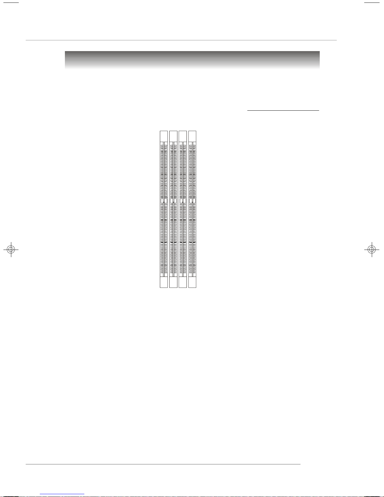
Memory
The mainboard provides 4 slots for 184-pin DDR SDRAM DIMM (Double In-Line Memory
Module) modules and supports the memory size up to 4GB. You can install DDR266/
333/400 modules on the DDR DIMM slots (DDR 1~4).
For the updated supporting memory modules, please visit http://www.msi.com.tw/
program/products/mainboard/mbd/pro_mbd_trp_list.php.
DIMM1~4
(from left to right)
Introduction to DDR SDRAM
DDR (Double Data Rate) SDRAM is similar to conventional SDRAM, but doubles the
rate by transferring data twice per cycle. It uses 2.5 volts as opposed to 3.3 volts
used in SDR SDRAM, and requires 184-pin DIMM modules rather than 168-pin DIMM
modules used by SDR SDRAM. High memory bandwidth makes DDR an ideal solution
for high performance PC, workstations and servers.
DIMM Module Combination
Install at least one DIMM module on the slots. Each DIMM slot supports up to a maximum
size of 1GB. Users can install either single- or double-sided modules to meet their
own needs. Please note that each DIMM can work respectively for single-
channel DDR, but there are some rules while using dual-channel DDR (Please
refer to the suggested DDR population table below). Users may install memory modules
of different type and density on different-channel DDR DIMMs. However, the same
type and density memory modules are necessary while using dual-channel DDR,
or instability may happen. Please refer to the following table for detailed dual-channel
DDR. Other combination not listed below will function as single-channel DDR.
2-7
Page 21
MS-7166 ATX Mainboard
Memory Module Population Rules
Install at least one DIMM module on the slots. Each DIMM slot supports up to a
maximum size of 1GB. Users can install either single- or double-sided modules to
meet their own needs. Please note that each DIMM can work respectively for
single-channel DDR, while both channels (in different color) populated
with same amount of memory size will work as dual-channel DDR.
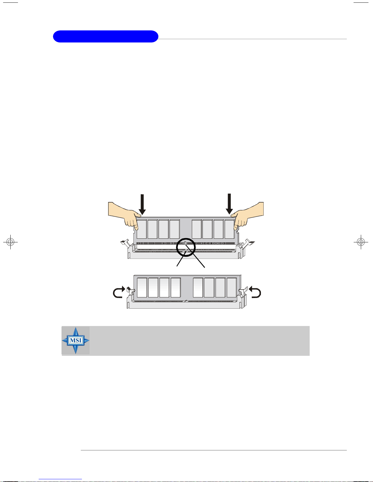
Installing DDR Modules
1. The DDR DIMM has only one notch on the center of module. The module will
only fit in the right orientation.
2. Insert the DIMM memory module vertically into the DIMM slot. Then push it in
until the golden finger on the memory module is deeply inserted in the socket.
3. The plastic clip at each side of the DIMM slot will automatically close.
Volt
MSI Reminds You...
You can barely see the golden finger if the module is properly inserted in the socket.
Notch
2-8
Page 22
Hardware Setup
Power Supply
The mainboard supports ATX power supply for the power system. Before
inserting the power supply connector, always make sure that all components are
installed properly to ensure that no damage will be caused.
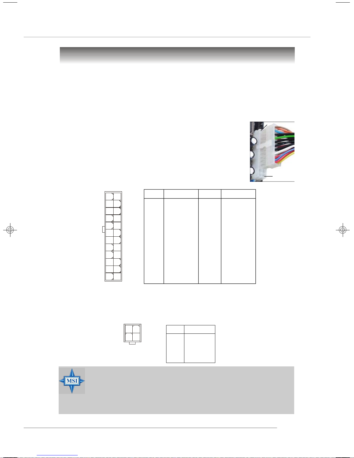
ATX 24-Pin Power Connector: ATX1
This connector allows you to connect an ATX 24-pin power supply. To
connect the ATX 24-pin power supply, make sure the plug of the
power supply is inserted in the proper orientation and the pins are
aligned. Then push down the power supply firmly into the connector.
You may use the 20-pin ATX power supply as you like. If
you’d like to use the 20-pin ATX power supply, please plug your
power supply along with pin 1 & pin 13 (refer to the image at the
right hand). There is also a foolproof design on pin 11, 12, 23 & 24
to avoid wrong installation.
Pin Definition
pin 13
pin 12
PIN SIGNAL
1 +3.3V
2 +3.3V
3 GND
4 +5V
5 GND
6 +5V
7 GND
8 PWR OK
9 5VSB
10 +12V
11 +12V
12 +3.3V
ATX1
13
24
1
12
ATX 12V Power Connector: JPW1
This 12V power connector is used to provide power to the CPU.
JPW1 Pin Definition
JPW1
2
4
1
3
PIN SIGNAL
1 GND
2 GND
3 12V
4 12V
PIN SIGNAL
13 +3.3V
14 -12V
15 GND
16 PS-ON#
17 GND
18 GND
19 GND
20 Res
21 +5V
22 +5V
23 +5V
24 GND
MSI Reminds You...
1. These two connectors connect to the ATX power supply and have to
work together to ensure stable operation of the mainboard.
2. Power supply of 350 watts (and above) is highly recommended for
system stability.
3. ATX 12V power connection should be greater than 18A.
2-9
Page 23
MS-7166 ATX Mainboard
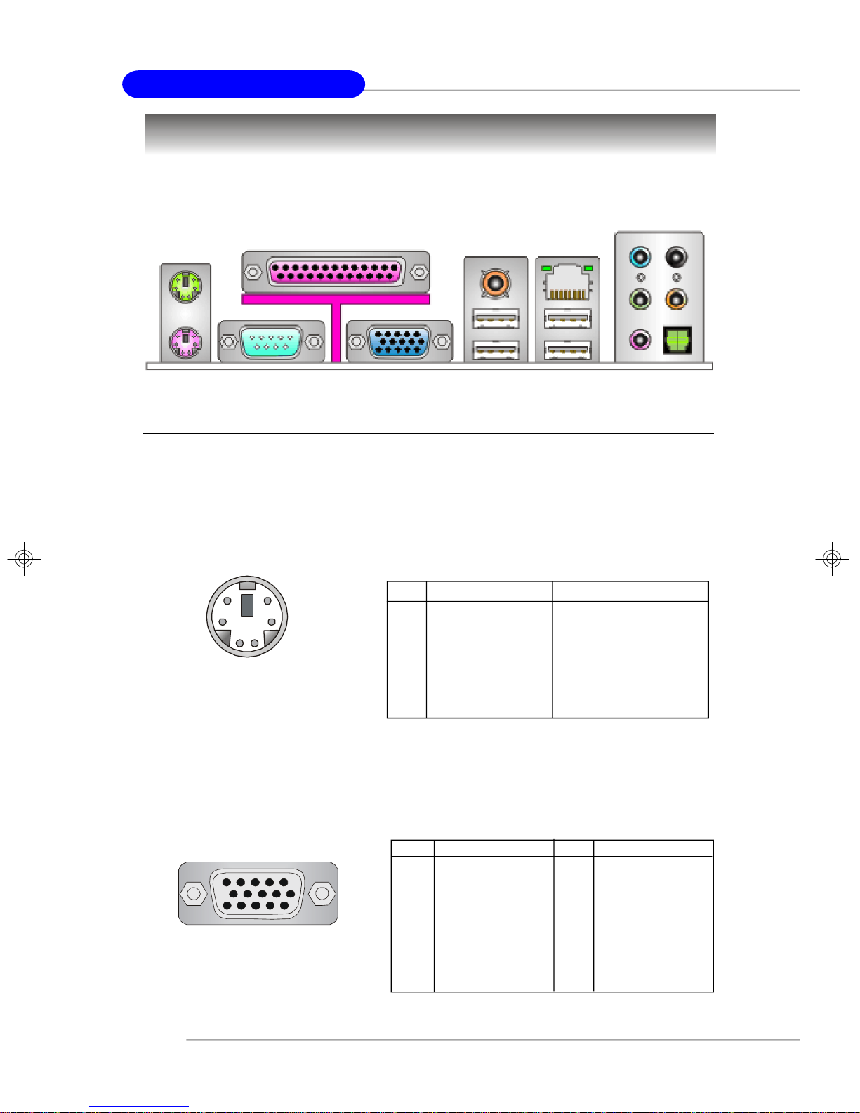
Back Panel
The back panel provides the following connectors:
RS-Out
CS-Out
SPDIF
Mouse
Keyboard
COM Port
Parallel
VGA port
(915G)
SPDIF
Out
USB Ports
L-In
LAN
L-Out
Mic
Out
Mouse/Keyboard Connector
The mainboard provides a standard PS/2® mouse/keyboard mini DIN connector
for attaching a PS/2® mouse/keyboard. You can plug a PS/2® mouse/keyboard directly
into this connector. The connector location and pin assignments are as follows:
Pin Definition
6
4
2
PS/2 Mouse / Keyboard
(6-pin Female)
5
3
1
PIN SIGNAL DESCRIPTION
1 Mouse/Keyboard Data Mouse/Keyboard data
2 NC No connection
3 GND Ground
4 VCC +5V
5 Mouse/Keyboard Clock Mouse/Keyboard clock
6 NC No connection
VGA Connector (Optional, for 915G only)
The mainboard provides a DB 15-pin female connector to connect a VGA
monitor.
5
15
VGA Connector
(DB 15-pin)
2-10
1
11
Pin Signal Description Pin Signal Description
1 RED 2 GREEN
3 BLUE 4 N/C
5 GND 6 GND
7 GND 8 GND
9 +5V 10 GND
11 N/C 12 SDA
13 Horizontal Sync 14 Vertical Sync
15 SCL
Page 24
Hardware Setup
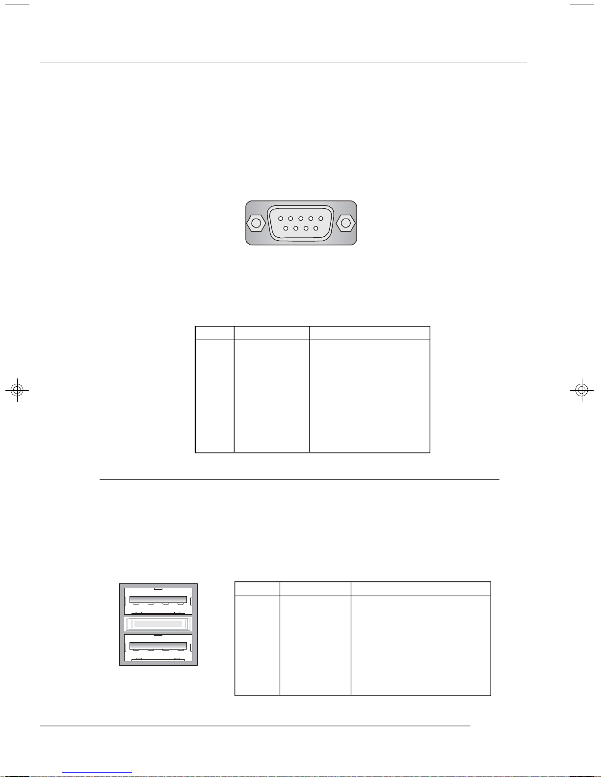
Serial Port Connector: COM Port
The mainboard offers one 9-pin male DIN connector COM Port. It’s a 16550A
high speed communication port that send/receive/ 16 bytes FIFOs. You can attach a
serial mouse or other serial device directly to it.
1 2 3 4 5
6 7 8 9
9-Pin Male DIN Connector
COM Port
Pin Definition
PIN SIGNAL DESCRIPTION
1 DCD Data Carry Detect
2 SIN Serial In or Receive Data
3 SOUT Serial Out or Transmit Data
4 DTR Data Terminal Ready)
5 GND Ground
6 DSR Data Set Ready
7 RTS Request To Send
8 CTS Clear To Send
9 RI Ring Indicate
USB Connectors
The mainboard provides an OHCI (Open Host Controller Interface) Universal
Serial Bus root for attaching USB devices such as keyboard, mouse or other USBcompatible devices. You can plug the USB device directly into the connector.
1 2 3 4
5 6 7 8
USB Ports
USB Port Description
PIN SIGNAL DESCRIPTION
1 VCC +5V
2 -Data 0 Negative Data Channel 0
3 +Data0 Positive Data Channel 0
4 GND Ground
5 VCC +5V
6 -Data 1 Negative Data Channel 1
7 +Data 1 Positive Data Channel 1
8 GND Ground
2-11
Page 25
MS-7166 ATX Mainboard
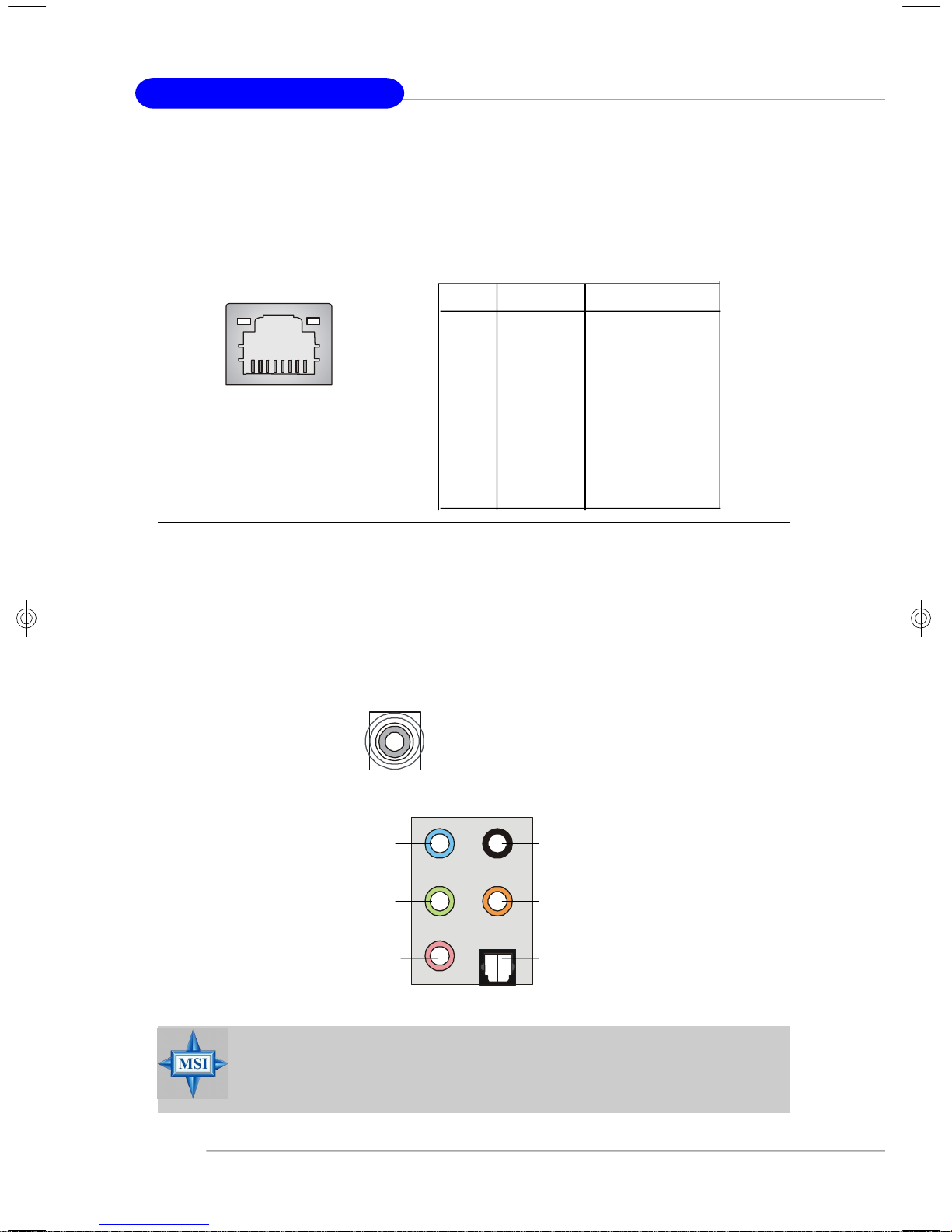
LAN (RJ-45) Jack
The mainboard provides 1 standard RJ-45 jack for connection to single Local
Area Network (LAN). This LAN enables data to be transferred at 1000Mbps, 100Mbps
or 10Mbps. You can connect a network cable to it.
Giga-bit LAN Pin Definition
PIN SIGNAL DESCRIPTION
1 D0P Differential Pair 0+
2 D0N Differential Pair 0-
3 D1P Differential Pair 1+
RJ-45 LAN Jack
4 D2P Differential Pair 2+
5 D2N Differential Pair 2-
6 D1N Differential Pair 1-
7 D3P Differential Pair 3+
8 D3N Differential Pair 3-
Audio Port Connectors
The left 3 audio jacks are for 2-channel mode for stereo speaker output: Line
Out is a connector for Speakers or Headphones. Line In is used for external CD
player, Tape player, or other audio devices. Mic is a connector for microphones.
However, there is an advanced audio application provided by Realtek ALC880
to offer support for 7.1-channel audio operation and can turn rear audio connectors
from 2-channel to 4-/5.1-/7.1- channel audio.
S/PDIF Out-Coaxial
Line In / Line Out
(Surround R/L)
(in 7.1 CH)
Line Out
(Front R/L)
MIC
Rear Speaker Out
(in 7.1CH / 5.1CH)
Center/Subwoofer
Speaker Out
( in 7.1CH / 5.1CH)
SPDIF-Out
MSI Reminds You...
For the advanced functions of the audio codec, please refer to Chapter
4: Introduction to Realtek ALC880 Audio Codec for details.
2-12
Page 26
Hardware Setup
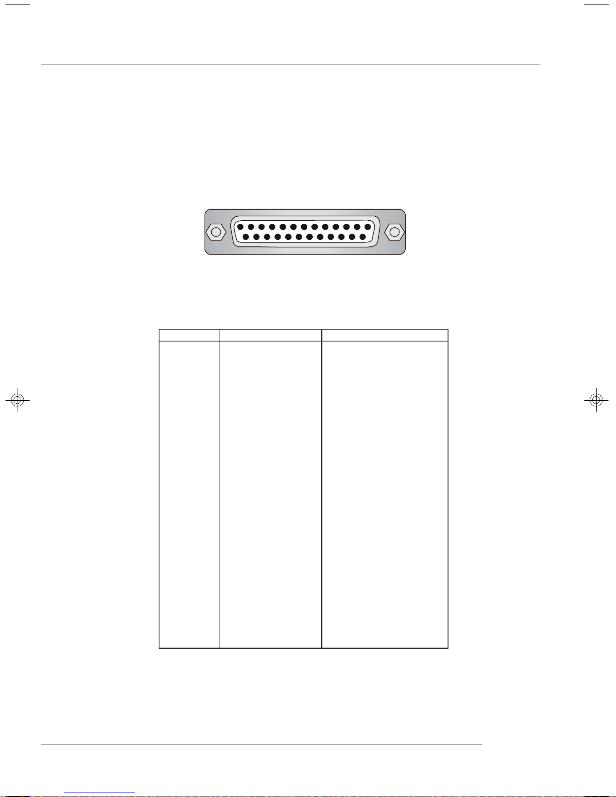
Parallel Port Connector: LPT1
The mainboard provides a 25-pin female centronic connector as LPT. A parallel
port is a standard printer port that supports Enhanced Parallel Port (EPP) and Extended Capabilities Parallel Port (ECP) mode.
13 1
25
14
Pin Definition
PIN SIGNAL DESCRIPTION
1 STROBE Strobe
2 DATA0 Data0
3 DATA1 Data1
4 DATA2 Data2
5 DATA3 Data3
6 DATA4 Data4
7 DATA5 Data5
8 DATA6 Data6
9 DATA7 Data7
10 ACK# Acknowledge
11 BUSY Busy
12 PE Paper End
13 SELECT Select
14 AUTO FEED# Automatic Feed
15 ERR# Error
16 INIT# Initialize Printer
17 SLIN# Select In
18 GND Ground
19 GND Ground
20 GND Ground
21 GND Ground
22 GND Ground
23 GND Ground
24 GND Ground
25 GND Ground
2-13
Page 27
MS-7166 ATX Mainboard
Connectors
The mainboard provides connectors to connect to FDD, IDE HDD, case, LAN,
and USB Ports.
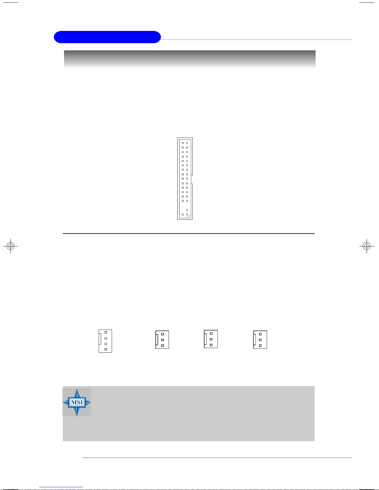
Floppy Disk Drive Connector: FDD1
The mainboard provides a standard floppy disk drive connector that supports
360K, 720K, 1.2M, 1.44M and 2.88M floppy disk types.
FDD1
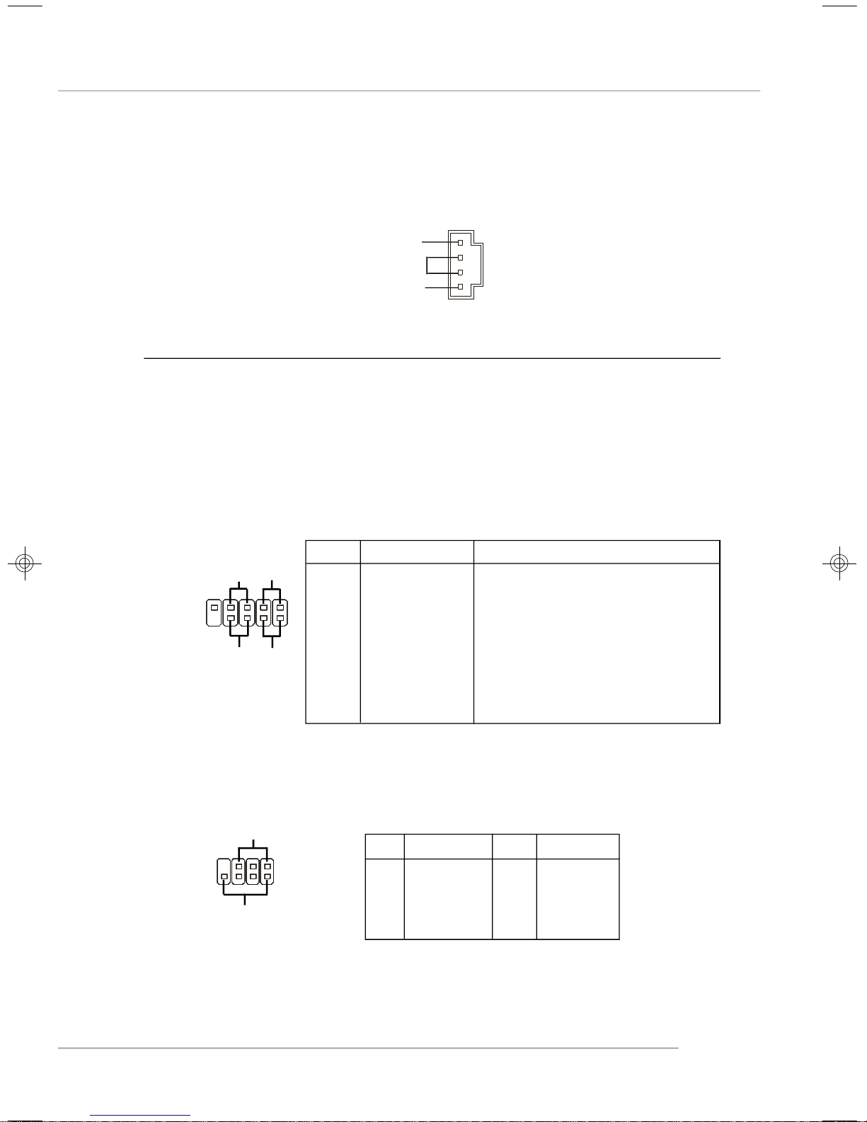
Fan Power Connectors: CPUFAN1/NBFAN1/SYSFAN1/PWRFAN1
The CPUFAN1 (processor fan), NBFAN1, SYSFAN1 and PWRFAN1 support
system cooling fan with +12V. It supports four/three-pin head connector. When
connecting the wire to the connectors, always take note that the red wire is the
positive and should be connected to the +12V, the black wire is Ground and should
be connected to GND. If the mainboard has a System Hardware Monitor chipset onboard, you must use a specially designed fan with speed sensor to take advantage
of the CPU fan control.
GND
+12V
SENSOR
Control
CPUFAN1
NBFAN1
GND
+12V
Sensor
SYSFAN1
MSI Reminds You...
1.Always consult the vendors for proper CPU cooling fan.
2.CPU_FAN supports the fan control. Fan/heatsink with 3 or 4 fins
are both available.
3.Please refer to the recommended CPU fans at Intel® official
website.
GND
+12V
Sensor
GND
+12V
Sensor
PWRFAN1
2-14
Page 28
Hardware Setup
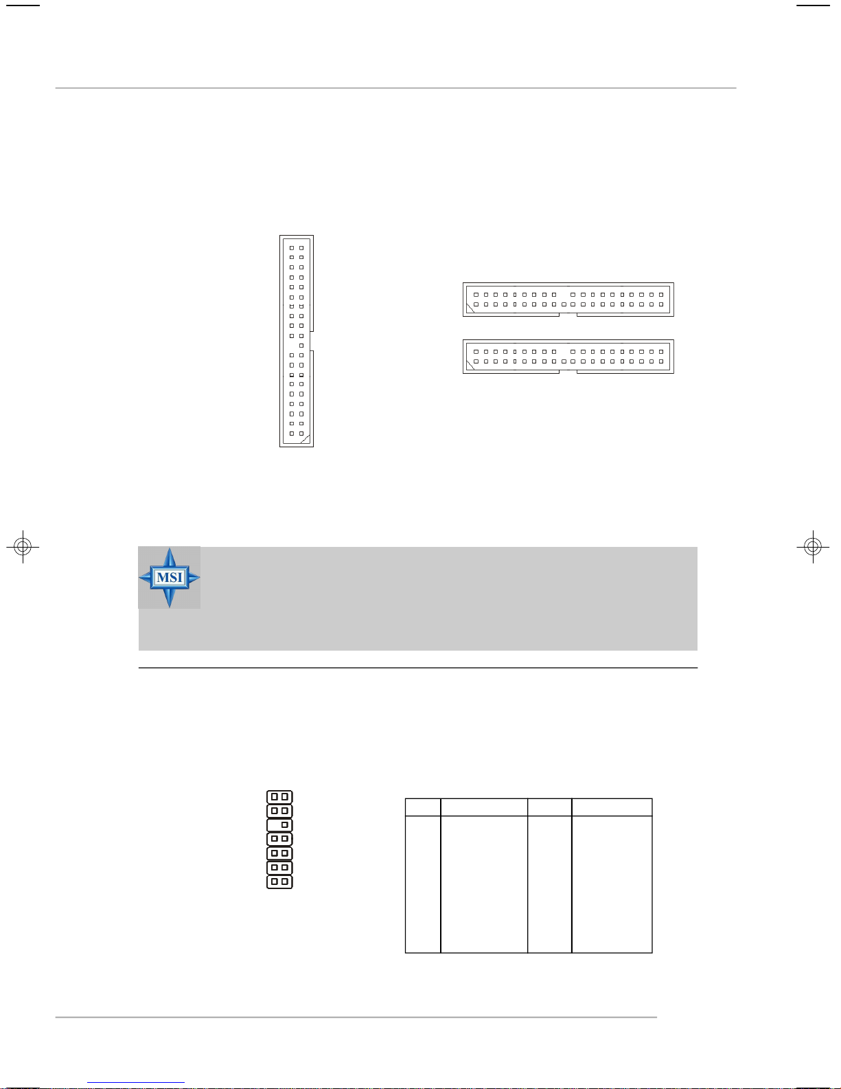
Hard Disk Connector: IDE1, IDE2, IDE3
The mainboard has 32-bit Ultra DMA 66/100 IDE controllers integrated in the
chips Intel ICH6 and VIA 6410, which supports PIO & Bus Master operation modes
and it can connect up to two Ultra ATA drives.
IDE2 (yellow)
IDE1 (blue)
IDE3 (yellow)
Note: When you use VIA VT6410 RAID IDE3 will
be Primary and IDE2 will be Secordary.
Each one can connect a Master and a Slave drive. You must configure second hard
drive to Slave mode by setting the jumper accordingly.
MSI Reminds You...
If you install two hard disks on cable, you must configure the second
drive to Slave mode by setting its jumper. Refer to the hard disk
documentation supplied by hard disk vendors for jumper setting
instructions.
FWH/LPC Debugging Pin Header: JLPC1
The pin header is for internal debugging only.
1314
2 1
JLPC1
JLPC1 Pin Definition
PIN SIGNAL PIN SIGNAL
1 LCLK 2 Key (no pin)
3 LRST# 4 VCC3
5 LAD0 6 FID0_LRST
7 LAD1 8 VCC5
9 LAD2 10 Key (no pin)
11 LAD3 12 GND
13 LFRAME# 14 GND
2-15
Page 29
MS-7166 ATX Mainboard
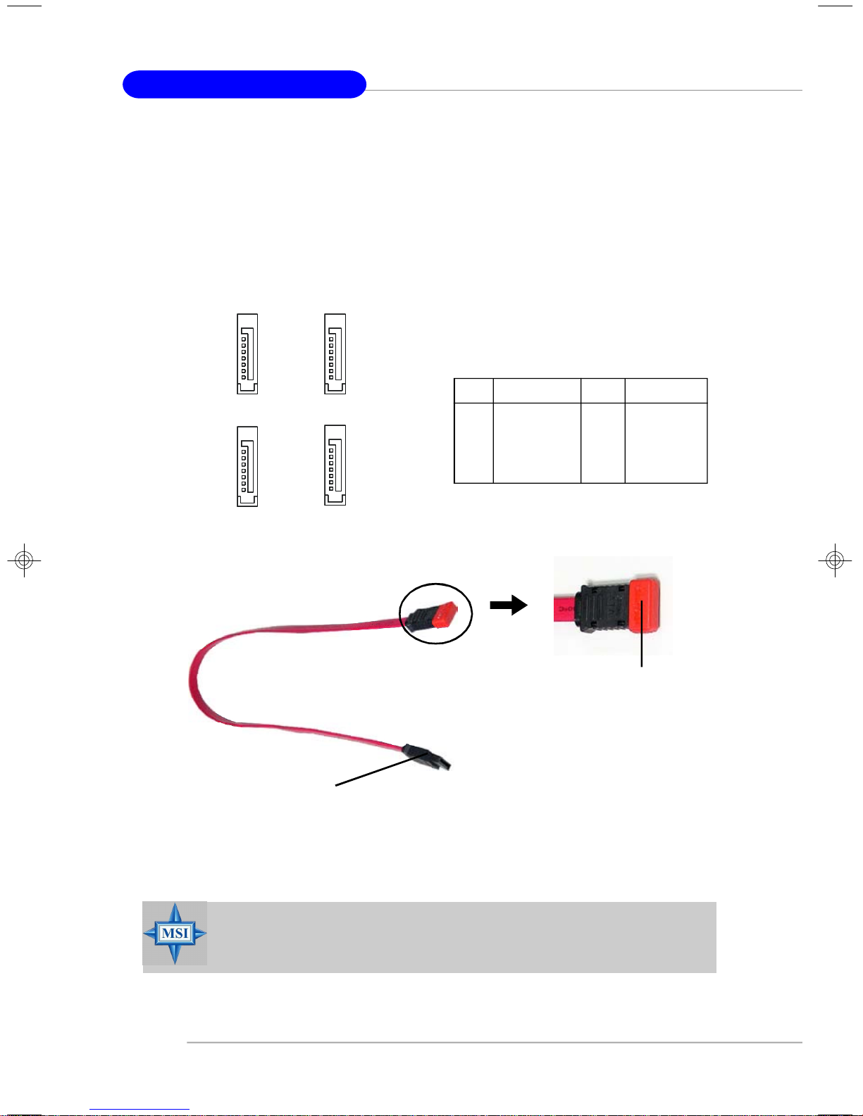
Serial ATA Connectors controlled by Intel ICH6: SATA1~SATA4
The SouthBridge of this mainboard is Intel ICH6 which supports four serial ATA
connectors SATA1~SATA4.
SATA1~SATA4 are dual high-speed Serial ATA interface ports. Each supports
1st generation serial ATA data rates of 150 MB/s. Both connectors are fully compliant
with Serial ATA 1.0 specifications. Each Serial ATA connector can connect to 1 hard
disk device.
1
7
SATA4
SATA3
SATA2 SATA1
Serial ATA cable
SATA1~ SATA4 Pin Definition
PIN SIGNAL PIN SIGNAL
1 GND 2 TXP
3 TXN 4 GND
5 RXN 6 RXP
7 GND
Take out the dust cover and
connect to the hard disk
devices
Connect to serial ATA ports
MSI Reminds You...
Please do not fold the serial ATA cable in a 90-degree angle, since
this might cause the loss of data during the transmission.
2-16
Page 30
Hardware Setup
CD-In Connector: JCD1
The connector is for CD-ROM audio connector.
R
JCD1
GND
L
Front Panel Connectors: JFP1 / JFP2
The mainboard provides two front panel connectors for electrical connection
to the front panel switches and LEDs. JFP1 is compliant with Intel® Front Panel I/O
Connectivity Design Guide.
JFP1
JFP2
JFP1 Pin Definition
Reset
HDD
Switch
LED
9
10
Power
Power
Switch
LED
Power
LED
7
8
Speaker
1
2
PIN SIGNAL DESCRIPTION
1 HD_LED_P Hard disk LED pull-up
2 FP PWR/SLP MSG LED pull-up
1
3 HD_LED_N Hard disk active LED
2
4 FP PWR/SLP MSG LED pull-up
5 RST_SW_N Reset Switch low reference pull-down to GND
6 PWR_SW_P Power Switch high reference pull-up
7 RST_SW_P Reset Switch high reference pull-up
8 PWR_SW_N Power Switch low reference pull-down to GND
9 RSVD_DNU Reserved. Do not use.
JFP2 Pin Definition
PIN SIGNAL PIN SIGNAL
1 GND 2 SPK-
3 SLED 4 BUZ+
5 PLED 6 BUZ-
7 NC 8 SPK+
2-17
Page 31

MS-7166 ATX Mainboard
Front USB Connectors: JUSB1 / JUSB2
The mainboard provides two standard USB 2.0 pin headers JUSB1 / JUSB2.
USB 2.0 technology increases data transfer rate up to a maximum throughput of
480Mbps, which is 40 times faster than USB 1.1, and is ideal for connecting high-
speed USB interface peripherals such as USB HDD, digital cameras, MP3 players,
printers, modems and the like.
JUSB1 / JUSB2 Pin Definition
PIN SIGNAL PIN SIGNAL
9
10
1
2
JUSB1 / JUSB2
(USB 2.0/standard spec)
MSI Reminds You...
Note that the pins of VCC and GND must be connected correctly, or it
may cause some damage.
1 VCC 2 VCC
3 USB0- 4 USB1-
5 USB0+ 6 USB1+
7 GND 8 GND
9 Key 10 USBOC
Front Panel Audio Connector: JAUD1
The F_AUDIO front panel audio connector allows you to connect to the front
panel audio and is compliant with Intel® Front Panel I/O Connectivity Design Guide.
2
1
PIN SIGNAL DESCRIPTION
1 PORT 1L Analog Port 1 - Left channel
2 GND Ground
3 PORT 1R Analog Port 1 - Right channel
4 PRESENCE# Active low signal - signals BIOS that a High Definition Audio
5 PORT 2R Analog Port 2 - Right channel
6 SENSE1_RETIRN Jack detection return from front panel JACK1
7 SENSE_SEND Jack detection sense line from the High Definition Audio CODEC
8 KEY Connector Key
9 PORT 2L Analog Port 2 - Left channel
10 SENSE2_RETIRN Jack detection return from front panel JACK2
10
9
JAUD1
JAUD1 Pin Definition
dongle is connected to the analog header. PRESENCE# = 0
when a High Definition Audio dongle is connected.
jack detection resistor network
2-18
Page 32

Hardware Setup
IrDA Infrared Module Header: JIR1
The connector allows you to connect to IrDA Infrared module. You must configure the setting through the BIOS setup to use the IR function. JIR1 is compliant with
Intel® Front Panel I/O Connectivity Design Guide.
Pin Definition
Pin Signal
5
6
JIR1
1
2
1 NC
2 NC
3 VCC5
4 GND
5 IRTX
6 IRRX
IEEE 1394 Connector: J1394_1/J1394_2 (Optional)
The mainboard provides two 1394 pin headers that allow you to connect
optional IEEE 1394 port.
9
10
1
2
J1394_1 / J1394_2
How to attach the IEEE 1394 Port:
Connected to J1394_1 / J1394_2
Pin Definition
PIN SIGNAL PIN SIGNAL
1 TPA+ 2 TPA-
3 Ground 4 Ground
5 TPB+ 6 TPB-
7 Cable power 8 Cable power
9 Key (no pin) 10 Ground
Foolproof
design
IEEE1394 Bracket (Optional)
2-19
Page 33

MS-7166 ATX Mainboard
D-Bracket™ 2 Connector: JDB1
The mainboard comes with a JDB1 connector for you to connect to D-Bracket™
2. D-Bracket™ 2 is a USB Bracket that supports both USB1.1 & 2.0 spec. It integrates
four LEDs and allows users to identify system problem through 16 various combinations of LED signals.
Pin Definition
Pin Signal
1 DBG1 (high for green color)
2 DBR1 (high for red color)
9
10
1
2
JDB1
3 DBG2 (high for green color)
4 DBR2 (high for red color)
5 DBG3 (high for green color)
6 DBR3 (high for red color)
7 DBG4 (high for green color)
8 DBR4 (high for red color)
9 Key
10 NC
D-Bracket™ 2
Connected to JDB1
Connected to JUSB1
(Optional)
LEDs
(the USB pinheader in YELLOW color)
D-Bracket™ 2 is an external USB bracket integrating four Diagnostic LEDs,
which use graphic signal display to help users understand their system. The LEDs
provide up to 16 combinations of signals to debug the system. The 4 LEDs can debug
all problems that fail the system, such as VGA, RAM or other failures. This special
feature is very useful for the overclocking users. These users can use the feature to
detect if there are any problems or failures.
D-Bracket™ 2 supports both USB 1.1 & 2.0 specification.
D-Bracket™ 2
2-20
1 2
3 4
Page 34

Hardware Setup
D-Bracket™ 2
1 2
3 4
Description
System Power ON
The D-LED will hang here if the processor is damaged or
not installed properly.
Early Chipset Initialization
Memory Detection Test
Testing onboard memory size. The D-LED will hang if the
memory module is damaged or not installed properly.
Decompressing BIOS image to RAM for fast booting.
Initializing Keyboard Controller.
Testing VGA BIOS
This will start writing VGA sign-on message to the screen.
Processor Initialization
This will show information regarding the processor (like
brand name, system bus, etc...)
Testing RTC (Real Time Clock)
Initializing Video Interface
This will start detecting CPU clock, checking type of video
onboard. Then, detect and initialize the video adapter.
BIOS Sign On
This will start showing information about logo, proces-
sor brand name, etc...
2-21
Page 35

MS-7166 ATX Mainboard
D-Bracket™ 2 Description
Testing Base and Extended Memory
Testing base memory from 240K to 640K and extended
memory above 1MB using various patterns.
Assign Resources to all ISA.
Initializing Hard Drive Controller
This will initialize IDE drive and controller.
Initializing Floppy Drive Controller
This will initialize Floppy Drive and controller.
Boot Attempt
This will set low stack and boot via INT 19h.
Operating System Booting
2-22
Page 36

Hardware Setup
Jumpers
Chassis Intrusion Switch Connector: JCI1
This connector is connected to a 2-pin chassis switch. If the chassis is opened,
the switch will be short. The system will record this status and show a warning
message on the screen. To clear the warning, you must enter the BIOS utility and
clear the record.
GND
CINTRU
2
1
JCI1
The motherboard provides the following jumpers for you to set the computer’s
function. This section will explain how to change your motherboard’s function through
the use of jumpers.
Clear CMOS Jumper: JBAT1
There is a CMOS RAM on board that has a power supply from external battery
to keep the system configuration data. With the CMOS RAM, the system can automatically boot OS every time it is turned on. If you want to clear the system configuration,
use the JBAT1 (Clear CMOS) Jumper to clear data. Follow the instructions below to
clear the data:
1
JBAT1
MSI Reminds You...
You can clear CMOS by shorting 2-3 pin while the system is off.
Then return to 1-2 pin position. Avoid clearing the CMOS while the
system is on; it will damage the mainboard.
3
1
Keep Data
3
1
Clear Data
2-23
Page 37

MS-7166 ATX Mainboard
Slots
The mainboard provides a PCI Express x16 slot, a PCI Express x1 slot and
three 32-bit PCI bus slots.
PCI Express Slots (optional)
The PCI Express slots, as a high-bandwidth, low pin count, serial, interconnect technology, support Intel highest performance desktop platforms utilizing the
Intel Pentium 4 processor with HT Technology.
PCI Express architecture provides a high performance I/O infrastructure for
Desktop Platforms with transfer rates starting at 2.5 Giga transfers per second over
a PCI Express x1 lane for Gigabit Ethernet, TV Tuners, 1394 controllers, and general
purpose I/O. Also, desktop platforms with PCI Express Architecture will be designed
to deliver highest performance in video, graphics, multimedia and other sophisticated
applications. Moreover, PCI Express architecture provides a high performance graphics
infrastructure for Desktop Platforms doubling the capability of existing AGP 8x designs with transfer rates of 4.0 GB/s over a PCI Express x16 lane for graphics
controllers.
You can insert the expansion cards to meet your needs. When adding or
removing expansion cards, make sure that you unplug the power supply first.
2-24
PCI Express x16 slot
PCI Express x1 slot
Page 38

Hardware Setup
PCI (Peripheral Component Interconnect) Slots
The PCI slots allow you to insert the expansion cards to meet your needs.
When adding or removing expansion cards, make sure that you unplug the power
supply first. Meanwhile, read the documentation for the expansion card to make any
necessary hardware or software settings for the expansion card, such as jumpers,
switches or BIOS configuration.
PCI Slots
PCI Interrupt Request Routing
The IRQ, acronym of interrupt request line and pronounced I-R-Q, are hardware lines over which devices can send interrupt signals to the microprocessor. The
PCI IRQ pins are typically connected to the PCI bus INT A# ~ INT D# pins as follows:
Order 1 Order 2 Order 3 Order 4
PCI Slot 1 INT A# INT B# INT C# INT D#
PCI Slot 2 INT B# INT C# INT D# INT A#
PCI Slot 3 INT C# INT D# INT A# INT B#
2-25
Page 39

BIOS Setup
Chapter 3. BIOS Setup
BIOS Setup
This chapter provides information on the BIOS Setup program and allows you
to configure the system for optimum use. You may need to run the Setup
program when:
² An error message appears on the screen during the system boot
up, and requests you to run SETUP.
² You want to change the default settings for customized features.
MSI Reminds You...
1. The items under each BIOS category described in this chapter are
under continuous update for better system performance.
Therefore, the description may be slightly different from the latest
BIOS and should be held for reference only.
2. While booting up, the BIOS version is shown in the 1st line appearing after the memory count. It is usually in the format:
example: W7166IMS V1.0BH 03/04/05
where:
1st digit refers to BIOS maker as A=AMI(R); W=AWARD(R)
2nd-5th digits refer to the model number.
6th digit refers to the customer, MS=all standard customers.
V1.0BH refers to the BIOS version.
03/04/05 refers to the date this BIOS is released.
3-1
Page 40

MS-7166 ATX Mainboard
Entering Setup
Power on the computer and the system will start POST (Power On Self Test)
process. When the message below appears on the screen, press <DEL> key to
enter Setup.
Press DEL to enter SETUP
If the message disappears before you respond and you still wish to enter
Setup, restart the system by turning it OFF and On or pressing the RESET button. You
may also restart the system by simultaneously pressing <Ctrl>, <Alt>, and <Delete>
keys.
Control Keys
<↑> Move to the previous item
<↓> Move to the next item
<←> Move to the item in the left hand
<→> Move to the item in the right hand
<Enter> Select the item
<Esc> Jumps to the Exit menu or returns to the main menu from a
submenu
<+> Increase the numeric value or make changes
<-> Decrease the numeric value or make changes
<F6> Load Fail-Safe Defaults
<F7> Load Optimized Defaults
<F10> Save all the CMOS changes and exit
Getting Help
After entering the Setup utility, the first screen you see is the Main Menu.
Main Menu
The main menu displays the setup categories the BIOS supplies. You can use the
arrow keys ( ↑↓ ) to select the item. The on-line description for the selected setup
category is displayed at the bottom of the screen.
Default Settings
The preset Optimal Defaults of the BIOS setup program provide optimal performance
settings for all devices and the system.
MSI Reminds You...
The items under each BIOS category described in this chapter are
under continuous update for better system performance. Therefore, the
description may be slightly different from the latest BIOS and should be
held for reference only.
3-2
Page 41

BIOS Setup
The Main Menu
Once you enter AwardBIOS CMOS Setup Utility, the Main Menu will appear on the
screen. Use arrow keys to move among the items and press <Enter> to enter the
sub-menu.
Standard CMOS Features
Use this menu for basic system configurations, such as time, date etc.
Advanced BIOS Features
Use this menu to setup the items of Award® special enhanced features.
Advanced Chipset Features
Use this menu to change the values in the chipset registers and optimize your system’s performance.
Integrated Peripherals
Use this menu to specify your settings for integrated peripherals.
Power Management Setup
Use this menu to specify your settings for power management.
PNP/PCI Configurations
This entry appears if your system supports PnP/PCI.
H/W Monitor
This entry shows the status of your CPU, fan, warning for overall system status.
Frequency/Voltage Control
Use this menu to specify your settings for frequency/voltage control.
3-3
Page 42

MS-7166 ATX Mainboard
Load BIOS Defaults
Use this menu to load the default values set by the BIOS vendor for stable system
performance.
Set Password
Use these two menus to set the passwords for BIOS.
Save & Exit Setup
Save changes to CMOS and exit setup.
Exit Without Saving
Abandon all changes and exit setup.
3-4
Page 43
BIOS Setup
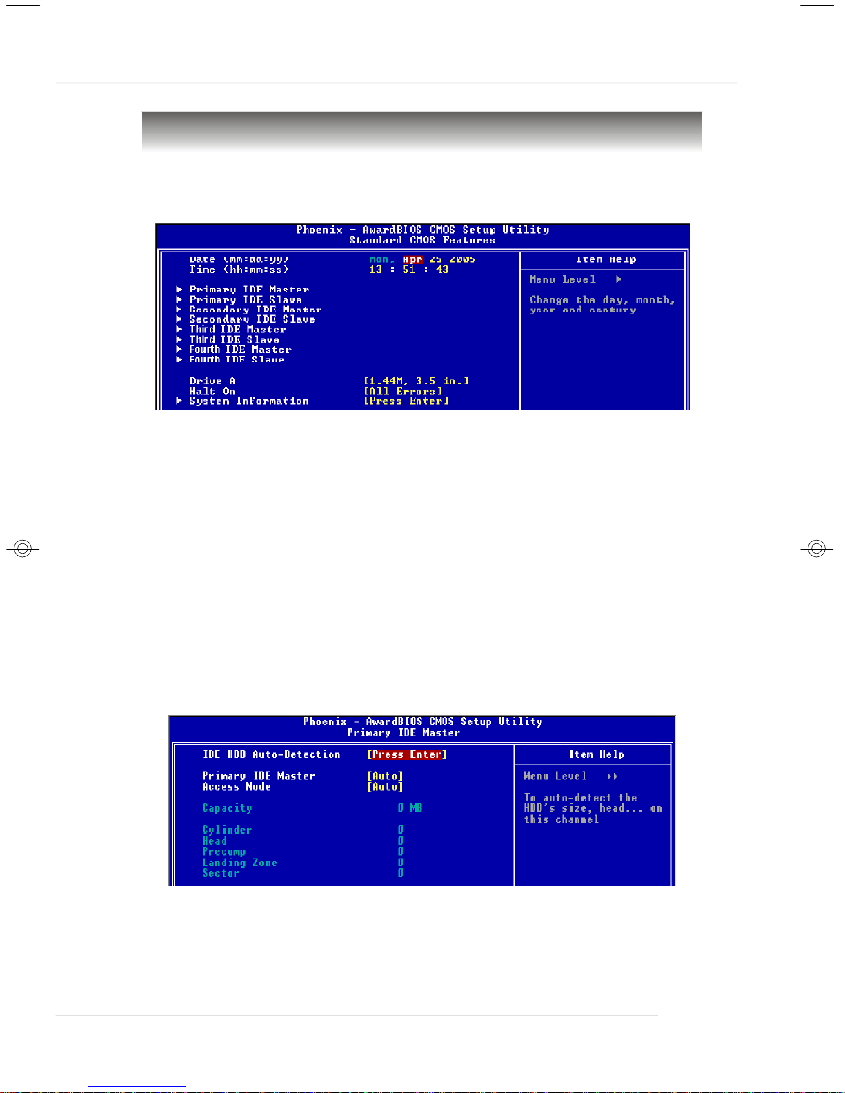
Standard CMOS Features
The items in Standard CMOS Features Menu includes some basic setup items. Use
the arrow keys to highlight the item and then use the <+> or <-> keys to select the
value you want in each item.
Date (MM:DD:YY)
This allows you to set the system to the date that you want (usually the current date).
The format is <day> <month> <date> <year>.
day Day of the week, from Sun to Sat, determined by BIOS. Read only.
month The month from Jan. through Dec.
date The date from 1 to 31 can be keyed by numeric function keys.
year The year can be adjusted by users.
Time (hh:mm:ss)
This allows you to set the system time that you want (usually the current time). The
time format is <hour> <minute> <second>.
Primary / Secondary / Third / Fourth IDE Master/Slave
Press <+> or <-> to select the hard disk drive type. The specification of hard disk
drive will show up on the right hand according to your selection. Press <Enter> for
the sub-menu of each item:
IDE HDD Auto-Detecion
Press <Enter> to auto-detect the hard disk’s size, head and other information on
this channel.
3-5
Page 44
MS-7166 ATX Mainboard
Primary IDE Master
Press PgUp/<+> or PgDn/<-> to select [Manual], [None] or [Auto] type. Note that
the specifications of your drive must match with the drive table. The hard disk
will not work properly if you enter improper information for this category. If your
hard disk drive type is not matched or listed, you can use [Manual] to define your
own drive type manually.
If you select [Manual], related information is asked to be entered to the following
items. Enter the information directly from the keyboard. This information should
be provided in the documentation from your hard disk vendor or the system
manufacturer.
Access Mode The settings are [CHS], [LBA], [Large], [Auto].
Capacity The formatted size of the storage device.
Cylinder Number of cylinders.
Head Number of heads.
Precomp Write precompensation.
Landing Zone Cylinder location of the landing zone.
Sector Number of sectors.
Drive A
This item allows you to set the type of the floppy drives installed. Available
options: [Disabled], [360 KB, 5
88MB, 3
1/2
].
1/4
], [1.2 MB, 5
1/4
], [720 KB, 3
1/2
], [1.44 MB, 3
1/2
], [2.
Halt On
The setting determines whether the system will stop if an error is detected at
boot. Available options are:
[All Errors] The system stops when any error is detected.
[No Errors] The system doesn’t stop for any detected error.
[All, But Keyboard] The system doesn’t stop for a keyboard error.
[All, But Diskette] The system doesn’t stop for a disk error.
[All, But Disk/Key]The system doesn’t stop for either a disk or a keyboard error.
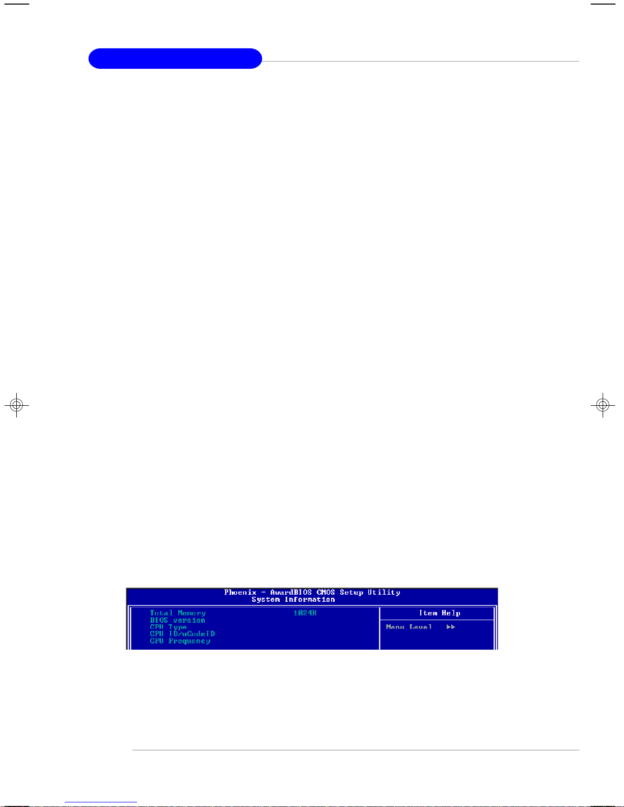
System Informaion
Press <Enter> for the sub-menu of each item:
Total Memory/BIOS versin/CPU Type/CPU ID/vCode ID/CPU Frequency
This item shows the memory status, BIOS version, CPU type, CPU ID/vCode ID/
CPU frequency of your system (read only).
3-6
Page 45

BIOS Setup
Advanced BIOS Features
CPU Feature
Press <Enter> to enter the sub-menu. This sub-menu only available with 6XX CPU.
C1E Support
Setting options: [Enabled], [Disabled].
Intel(R) SpeedStep(tm)tech
This item is available when you install CPU support EIST. Setting options: [Enabled],
[Disabled]
Thermal Management
Setting options: [Thermal Monitor 1], [Thermal Monitor 2.]
Limit CPUID MaxVal
Setting options: [Enabled], [Disabled].
NX BIOS Control
Setting options: [Enabled], [Disabled]
Boot Sequence
Press <Enter> to enter the sub-menu.
The original IBM PCs loaded the DOS operating system from drive A (floppy disk), so
IBM PC-compatible systems are designed to search for an operating system first on
drive A, and then on drive C (hard disk). However, modern computers usually load
the operating system from the hard drive, and may even load it from a CD-ROM drive.
3-7
Page 46

MS-7166 ATX Mainboard
Hard Disk Boot Priority
Press <Enter> to enter the sub-menu. Then you may use the arrow keys ( -Ż ) to
select the desired device, then press <+>, <-> or <PageUp>, <PageDown> key to
move it up/down in this hard disk boot priority list.
1st/2nd/3rd Boot Device
These items allow you to set the sequence of boot devices where BIOS attempts
to load the operating system.
Boot From Other Devices
Setting the option to [Enabled] allows the system to try to boot from other devices
if the system fails to boot from the 1st/2nd/3rd boot device. Settings are: [Disabled],
[Enabled].
MSI Reminds You...
Available settings for “1st/2nd/3rd Boot Device” vary depending on
the bootable devices you have installed. For example, if you did not
install a floppy drive, the setting “Floppy” will not show up.
Boot Sector Protection
This function protects the BIOS from accidental corruption by unauthorized users or
computer viruses. When enabled, the BIOS’ data cannot be changed when attempting to update the BIOS with a Flash utility. To successfully update the BIOS, you’ll
need to disable this Flash BIOS Protection function.
You should enable this function at all times. The only time when you need to disable
it is when you want to update the BIOS. After updating the BIOS, you should immediately re-enable it to protect it against viruses. Setting options: [Enabled], [Disabled].
Hyper-Threading Technology
The processor uses Hyper-Threading technology to increase transaction rates and
reduces end-user response times. The technology treats the two cores inside the
processor as two logical processors that can execute instructions simultaneously.
In this way, the system performance is highly improved. If you disable the function,
the processor will use only one core to execute the instructions. Settings: [Enabled],
[Disabled].
MSI Reminds You...
Enabling the functionality of Hyper-Threading Technology for your computer system requires ALL of the following platform Components:
* CPU: An Intel® Pentium® 4 Processor with HT Technology;
* Chipset: An Intel® Chipset that supports HT Technology;
* BIOS: A BIOS that supports HT Technology and has it enabled;
* OS: An operating system that supports HT Technology.
For more information on Hyper-threading Technology, go to:
www.intel.com/info/hyperthreading
3-8
Page 47

BIOS Setup
Quick Boot
Setting the item to [Enabled] allows the system to boot within 5 seconds since it will
skip some check items. Available options: [Enabled], [Disabled].
MPS Table Version
This field allows you to select which MPS (Multi-Processor Specification) version to
be used for the operating system. You need to select the MPS version supported by
your operating system. To find out which version to use, consult the vendor of your
operating system. Settings: [1.4], [1.1].
Boot to OS/2
This allows you to run the OS/2® operating system with DRAM greater than 64MB.
Setting options: [Yes], [No].
Full Screen LOGO Display
This item enables you to show the company logo on the bootup screen. Settings are:
[Enabled] Shows a still image (logo) on the full screen at boot.
[Disabled] Shows the POST messages at boot.
3-9
Page 48

MS-7166 ATX Mainboard
Advanced Chipset Features
MSI Reminds You...
Change these settings only if you are familiar with the chipset.
DRAM Timing Selectable
Selects whether DRAM timing is controlled by the SPD (Serial Presence Detect)
EEPROM on the DRAM module. Setting to [By SPD] enables DRAM timings and the
following related items to be determined by BIOS based on the configurations on the
SPD. Selecting [Manual] lets users configure the DRAM timings and the following
related items manually. Setting options: [Manual], [By SPD].
CAS Latency Time
This controls the CAS latency, which determines the timing delay (in clock cycles)
before SDRAM starts a read command after receiving it. Settings: [Auto], [2], [2.5],
[3]. [2] increases the system performance the most while [3] provides the most stable
performance.
DRAM RAS# to CAS# Delay
When DRAM is refreshed, both rows and columns are addressed separately. This
setup item allows you to determine the timing of the transition from RAS (row address
strobe) to CAS (column address strobe). The less the clock cycles, the faster the
DRAM performance. Setting options: [Auto], [2], [3], [4], [5].
DRAM RAS# Precharge
This item controls the number of cycles for Row Address Strobe (RAS) to be allowed
to precharge. If insufficient time is allowed for the RAS to accumulate its charge
before DRAM refresh, refresh may be incomplete and DRAM may fail to retain data.
This item applies only when synchronous DRAM is installed in the system. Setting
options: [Auto], [2], [3], [4], [5].
3-10
Page 49

BIOS Setup
Precharge delay (tRAS)
This setting determines the precharge delay, which determines the timing delay for
DRAM precharge. Setting options: [Auto], [4], [5], [6], [7], [8], [9], [10], [11], [12], [13],
[14], [15].
Adjust DDR Frequency
When it is set to [Manual] in High Performance Mode, user can place an artificial
memory clock limit on the system. Please note that memory is prevented from running
faster than this frequency. Setting options: [Auto], [333 MHz], [400 MHz].
Memory Hole
In order to improve performance, certain space in memory can be reserved for ISA
peripherals. This memory must be mapped into the memory space below 16MB. When
this area is reserved, it cannot be cached. Settings: [Disabled], [15MB-16MB].
PCI Express Root Port Func
Press <Enter> to enter the sub-menu.
PCI Express Port
Settin options: [Auto], [Disabled], [Enabled]
PCI-E Compliancy Mode
This field allows you to select the PCI-E specification version. Setting options: [v1.
0a], [v1.0].
** VGA Setting **
On-Chip VGA
This setting determines whether the system RAM can be allocated to on-chip video
controller for video purposes. When setting to Enabled, up to 128MB system RAM
will be allocated to on-chip video controller. Setting options: [Enabled] and [Disabled].
On-Chip Frame Buffer Size
Frame Buffer is the video memory that stores data for video display (frame). This field
is used to determine the memory size for Frame Buffer. Larger frame buffer size
increases video performance. Setting options: [1MB], [4MB], [8MB], [16MB], [32MB].
FIXED Memory Size
This field specifies the size of system memory to allocate for video memory. Setting
options: [64MB], [128MB].
DVMT Memory Size
This field specifies the size of DVMT (Dynamic Video Memory Technology) memory to
allocate for video memory. Setting options: [64MB], [128MB].
Boot Display
Use the field to select the type of device you want to use as the display(s) of the
system. Setting options: [Auto], [CRT], [TV], [EFP]. The option [EFP] refers to the LCD
display.
3-11
Page 50

MS-7166 ATX Mainboard
Integrated Peripherals
USB Controller
This setting is used to enable/disable the onboard USB host controller. Setting options:
[Disabled], [Enabled].
USB 2.0 Controller
Set to [Enabled] if you need to use any USB 2.0 device in the operating system that
does not support or have any USB 2.0 driver installed, such as DOS and SCO Unix.
Setting options: [Disabled], [Enabled].
USB Keyboard/Mouse Support
Set to [Enabled] if you need to use a USB keyboard/mouse in the operating system
that does not support or does not have any USB driver installed, such as DOS and
SCO Unix. Settings: [Enabled], [Disabled].
Azalia/AC97 Selection
[Auto] allows the mainboard to detect whether an audio device is used. If an audio
device is detected, the onboard AC’97 (Audio Codec’97) controller will be enabled; if
not, it is disabled. Disable the controller if you want to use other controller cards to
connect an audio device. The settings are: [Enabled], [Disabled].
Onboard LAN Controller
The item enables or disables the onboard LAN device. Setting options: [Enabled],
[Disabled].
Onboard Lan Boot ROM
The items enable or disable the initialization of the onboard LAN Boot ROMs during
bootup. Selecting Disabled will speed up the boot process.
Onboard RAID control
The item enables or disables the onboard RAID controller. Setting options: [Enabled],
[Disabled].
3-12
Page 51

BIOS Setup
Onboard VIA RAID Mode
The item allows you to select the onboard VIA RAID mode. Setting options: [IDE],
[RAID].
OnBoard 1394 control
This setting is used to enable/disable the onboard VIA 1394 controller. Setting options:
[Enabled], [Disabled].
IO Devices Configuration
Press <Enter> to enter the sub-menu and the following screen appears:
Onboard FDC Controller
Select [Enabled] if your system has a floppy disk controller (FDC) installed on the
system board and you wish to use it. If you install add-on FDC or the system has
no floppy drive, select [Disabled] in this field. Setting options: [Enabled], [Disabled].
COM Port 1
These items specify the base I/O port addresses of the onboard Serial Port 1 .
Selecting [Auto] allows BIOS to automatically determine the correct base I/O port
address. Settings: [3F8/IRQ4], [2F8/IRQ3], [3E8/IRQ4], [2E8/IRQ3] and [Disabled].
UR2 Duplex Mode
This setting controls the operating mode of IR transmission/reception. Setting
options: [Full], [Half]. Under [Full] Duplex mode, synchronous, bi-directional transmission/reception is allowed. Under [Half] Duplex mode, only asynchronous, bidirectional transmission/reception is allowed.
Use IR Pins
Consult your IR peripheral documentation to select the correct setting of the TxD
and RxD signals.
Onboard Parallel Port
There is a built-in parallel port on the on-board Super I/O chipset that provides
Standard, ECP, and EPP features. It has the following options:
[Disabled]
[3BC/IRQ7]Line Printer port 0
[278/IRQ5] Line Printer port 2
[378/IRQ7] Line Printer port 1
3-13
Page 52

MS-7166 ATX Mainboard
Parallel Port Mode
[SPP] Standard Parallel Port
[EPP] Enhanced Parallel Port
[ECP] Extended Capability Port
[ECP + EPP]Extended Capability Port + Enhanced Parallel Port
To operate the onboard parallel port as Standard Parallel Port only, choose [SPP].
To operate the onboard parallel port in the EPP mode simultaneously, choose [EPP].
By choosing [ECP], the onboard parallel port will operate in ECP mode only. Choosing [ECP + EPP] will allow the onboard parallel port to support both the ECP and EPP
modes simultaneously.
EPP Mode Select
The onboard parallel port is EPP Spec. compliant, so after the user chooses the
onboard parallel port with the EPP function, the following message will be displayed on the screen: “EPP Mode Select.” At this time either [EPP 1.7] spec or [EPP
1.9] spec can be chosen.
ECP Mode Use DMA
The ECP mode has to use the DMA channel, so choose the onboard parallel port
with the ECP feature. After selecting it, the following message will appear: “ECP
Mode Use DMA.” At this time, the user can choose between DMA channel [3] or
[1].
IDE Devices Configuration
Press <Enter> to enter the sub-menu and the following screen appears:
PCI IDE BusMaster
Set this option to [Enabled] to specify that the IDE controller on the PCI local bus
has bus mastering capability. Settings options: [Disabled], [Enabled].
OnChip Primary PCI IDE
The integrated peripheral controller contains an IDE interface with support for the
IDE channel. Choose [Enabled] to activate the channel. Setting options: [Enabled],
[Disabled].
3-14
Page 53

BIOS Setup
IDE Primary Master/Slave PIO
The four IDE PIO (Programmed Input/Output) fields let you set a PIO mode (0-4) for
each of the four IDE devices that the onboard IDE interface supports. Modes 0
through 4 provide successively increased performance. In [Auto] mode, the system automatically determines the best mode for each device. Setting options are:
[Auto], [Mode 0], [Mode 1], [Mode 2], [Mode 3], [Mode 4].
IDE Primary Master/Slave UDMA
Ultra DMA/33 implementation is possible only if your IDE hard drive supports it and
the operating environment includes a DMA driver (Windows 95 OSR2 or a thirdparty IDE bus master driver). If your hard drive and your system software both
support Ultra DMA/33, Ultra DMA/66 and Ultra DMA/100, select Auto to enable
BIOS support. Setting optons are: [Auto], [Disabled].
SATA Devices Configuration
Press <Enter> to enter the sub-menu and the following screen appears:
*** On Chip Serial ATA Setting ***
SATA Mode
This setting is used to select the SATA mode. The setting are:
[IDE] no AHCI, no RAID
[SATA]AHCI enabled, RAID enabled
[AHCI] AHCI enabled, no RAID
Advanced Host Controller Interface (AHCI) includes a description of the hardware/
software interface between system software and the host controller hardware.
On-Chip Serial ATA
This setting is used to specify the SATA controller. The settings are:
[Disabled] Select this if you want to disable both SATA controller.
[Combined]You can use the IDE channels with S-ATA and P-ATA devices, and
maximum of 2 devices in each channel are supported (maxinum of 4
devices). Refer to the table below for the combination.
[Enhanced]Enable both S-ATA and P-ATA devices, and maximum of 6 devices are
supported (maxinum of 4 SATA devices).
[Auto] Let the system arrange automatically.
[SATA Only]SATA is operating in legacy mode.
PATA IDE Mode/ SATA Port
This Item allows you to set the parallel IDE and the SATA port operation mode.
Setting options: [Primary], [Secondary].
3-15
Page 54

MS-7166 ATX Mainboard
Power Management Features
MSI Reminds You...
S3-related functions described in this section are available only
when your BIOS supports S3 sleep mode.
ACPI Standby State
This item specifies the power saving modes for ACPI function. If your operating
system supports ACPI, such as Windows 98SE, Windows ME and Windows 2000,
you can choose to enter the Standby mode in S1 (POS) or S3 (STR) fashion through
the setting of this field. Options are:
[S1(POS)]The S1 sleep mode is a low power state. In this state, no system
context is lost (CPU or chipset) and hardware maintains all system context.
[S3(STR)]The S3 sleep mode is a lower power state where the information
of system configuration and open applications/files is saved to
main memory that remains powered while most other hardware
components turn off to save energy. The information stored in
memory will be used to restore the system when a “wake up”
event occurs.
Re-Call VGA BIOS from S3
When ACPI Standby State is set to [S3/STR], users can select the options in this
field. Selecting [Yes] allows BIOS to call VGABIOS to initialize the VGA card when
system wakes up (resumes) from S3 sleep state. The system resume time is shortened when you disable the function, but system will need an AGP driver to initialize
the VGA card. Therefore, if the AGP driver of the card does not support the initialization feature, the display may work abnormally or not function after resuming from S3.
Options: [Auto], [Yes], [No].
3-16
Page 55

BIOS Setup
Suspend Time Out (Minute)
If system activity is not detected for the length of time specified in this field, all
devices except CPU will be shut off. Settings: [Disabled], [1], [2], [4], [8], [10], [20],
[30], [40], [50], [60].
Power Button Function
This feature allows users to configure the Power Button function. Settings are:
[Power Off] The power button functions as a normal power-on/-off button.
[Suspend] When you press the power button, the computer enters the
suspend/sleep mode, but if the button is pressed for more
than four seconds, the computer is turned off.
Wakeup Event Setup
Press <Enter> and the following sub-menu appears.
PCI Express PME
When setting to [Enabled], this setting allows your system to be awakened by PCI
Express Device from the power saving modes through any event on PME (Power
Management Event). Setting options: [Disabled], [Enabled].
Resume From S3 by USB
The item allows the activity of the USB device to wake up the system from S3
(Suspend to RAM) sleep state. Setting options: [Disabled], [Enabled].
Resume by RTC Alarm
This is used to enable or disable the feature of booting up the system on a
scheduled time/date from the S3, S4, and S5 power off state. Setting options:
[Disabled], [Enabled].
Date (of Month) Alarm
The field specifies the date for Resume by RTC Alarm. Settings: [0]~[31].
Time (hh:mm:ss) Alarm
The field specifies the time for Resume by RTC Alarm. Format is <hour><minute>
<second>.
POWER ON Function
This controls how the PS/2 mouse or keyboard can power on the system. Settings:
[Password], [Hot KEY], [Mouse Left], [Mouse Left], [Mouse Right], [any KEY],
[BUTTON ONLY], [Keyboard 98].
3-17
Page 56

MS-7166 ATX Mainboard
KB Power ON Password
If POWER ON Function is set to Password, then you can set a password in the
field for the PS/2 keyboard to power on the system.
Hot Key Power ON
If POWER ON Function is set to [Hot KEY], you can assign a hot key combination
in the field for the PS/2 keyboard to power on the system. Settings: [Ctrl-F1]
through [Ctrl-F12].
Restore on AC/Power Loss
This setting specifies whether your system will reboot after a power failure or
interrupt occurs. Available settings are:
[Off] Leaves the computer in the power off state.
[On] Leaves the computer in the power on state.
[Last State] Restores the system to the previous status before power
failure or interrupt occurred.
3-18
Page 57

BIOS Setup
PNP/PCI Configurations
This section describes configuring the PCI bus system and PnP (Plug & Play) feature.
PCI, or Peripheral Component Interconnect, is a system which allows I/O devices to
operate at speeds nearing the speed the CPU itself uses when communicating with
its special components. This section covers some very technical items and it is
strongly recommended that only experienced users should make any changes to the
default settings.
Init Display First
This setting specifies which VGA card is your primary graphics adapter. Setting
options are:
[PCI Slot] The system initializes the PCI Graphic card first. If a PCI Graphic card
is not available, it will initialize the PCI Express graphic.
[Onboard] The system initializes the Onboard Graphic card first.
[PCI -E] The system initializes the PCI Express graphic first. If a PCI Express
graphic card is not available, it will initialize the PCI graphic card.
PCI Slot1~4 IRQ
These items specify the IRQ line for each PCI slot. Setting options: [3], [4], [5], [7], [9],
[10], [11], [12], [14], [15], [Auto]. Selecting [Auto] allows BIOS to automatically determine the IRQ line for each PCI slot.
**PCI Express relative items**
Maximum Payload Size
This item allows you to set the maximum TLP (transaction layer packet) payload size
for the PCI Express devices. Setting options: [128], [256], [512], [1024], [2048], [4096].
3-19
Page 58

MS-7166 ATX Mainboard
H/W Monitor
This section shows the status of your CPU, fan, overall system status, etc. Monitor
function is available only if there is hardware monitoring mechanism onboard.
Chassis Intrusion Detect
The field enables or disables the feature of recording the chassis intrusion status
and issuing a warning message if the chassis is once opened. To clear the warning
message, set the field to [Reset]. The setting of the field will automatically return to
[Enabled] later. Setting options: [Enabled], [Reset], [Disabled].
CPU Smart Fan Temperature.
When the current temperature of the CPU fan reaches the value you specify here,
the CPU fan will speed up for cooling down to avoid the CPU damage; on the contrary,
if the CPU fan current temperature is lower than the specified value, the CPU fan will
slow down its speed to keep the temperature stable. You may also choose [Disabled]
to disable the CPU Smart Fan function.
CPU Temperature Tolerance
You can select a fan tolerance value here for the specific range for the CPU Smart
Fan Temp. item. If the current temperature of the CPU fan reaches the maximum
threshold (the temperature set in the CPU Smart Fan Temp. plus the tolerance
value you set here), the fan will speed up for cooling down. On the contrary if the
current temperature reaches the minimum threshold (the set temperatures minus the
tolerance value), the fan will slow down to keep the temperatures stable.
3-20
Page 59
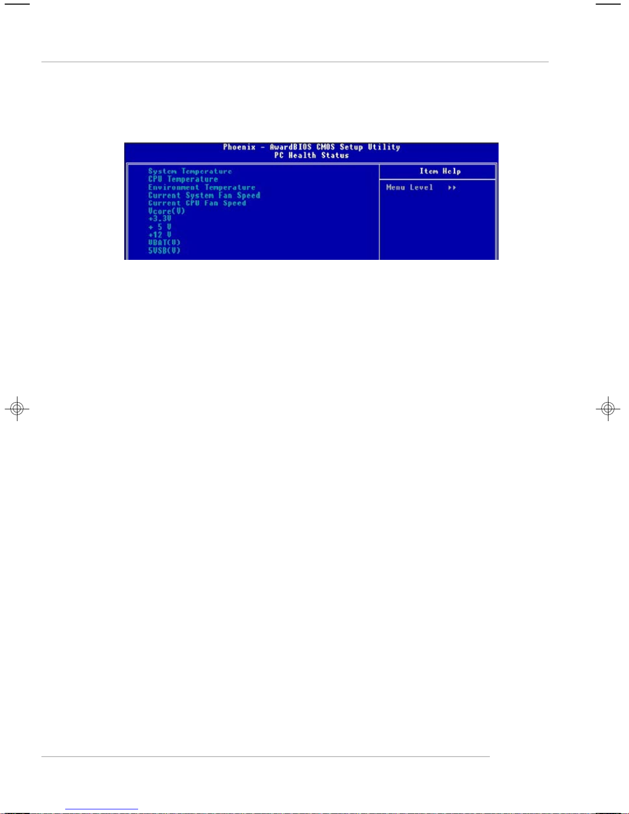
BIOS Setup
PC Health Status
Press <Enter> and the following sub-menu appears.
System/ CPU/ Environment Temperature, Current System/CPU Fan Speed,
Vcore(V), +3.3V, +5 V, +12 V, VBAT(V), 5VSB (V).
These items display the current status of all of the monitored hardware devices/
components such as CPU voltages, temperatures and all fans’ speeds.
3-21
Page 60

MS-7166 ATX Mainboard
Frequency/Voltage Control
The items here includes some important settings of CPU and PCI functions.
MSI Reminds You...
Change these settings only if you are familiar with the chipset.
Current CPU Clock
This item only displays the current CPU clock.
Dynamic OverClocking
Dynamic Overclocking Technology is the automatic overclocking function, included in
the MSITM’s newly developed CoreCell
TM
Technology. It is designed to detect the load
balance of CPU while running programs, and to adjust the best CPU frequency
automatically. When the motherboard detects CPU is running programs, it will speed
up CPU automatically to make the program run smoothly and faster. When the CPU is
temporarily suspending or staying in the low load balance, it will restore the default
settings instead. Usually the Dynamic Overclocking Technology will be powered only
when users' PC need to run huge amount of data like 3D games or the video process,
and the CPU frequency need to be boosted up to enhance the overall performance.
Setting options:
[Disabled] Disable Dynamic Overclocking.
[Private] 1st level of overclocking, increasing the CPU frequency by 1%.
[Sergeant] 2nd level of overclocking, increasing the CPU frequency by 3%.
[Captain] 3rd level of overclocking, also the default value of "Load High
Performance Defaults", increasing the CPU frequency by 5%.
[Colonel] 4th level of overclocking, increasing the CPU frequency by 7%.
[General] 5th level of overclocking, increasing the CPU frequency by 10%.
[Commander] 6th level of overclocking, increasing the CPU frequency by 15%.
3-22
Page 61

BIOS Setup
MSI Reminds You...
1. Even though the Dynamic Overclocking Technology is more stable
than manual overclocking, basically, it is still risky. We suggest
user to make sure that your CPU can afford to overclocking regularly first. If you find the PC appears to be unstable or reboot
incidentally, it's better to disable the Dynamic Overclocking or to
lower the level of overclocking options. By the way, if you need to
conduct overclocking manually, you also need to disable the Dynamic OverClocking first.
2. Meanwhile, there are two functions to protect user's system from
crash.
- There is a safe key "Ins" in BIOS. In case the overclocking
fails, you can press "Ins" key while system rebooting to
restore to the BIOS defaults.
- If the system incidentally reboot for four times, the BIOS will
also be restored to the defaults.
Adjust CPU Clock Ratio
This item allows you to adjust the CPU ratio. Setting range is from [8X] to [50X].
Auto Detect PCI Clk
This item is used to auto detect the PCI slots. When set to [Enabled], the system will
remove (turn off) clocks from empty PCI slots to minimize the electromagnetic interference (EMI). Settings: [Enabled], [Disabled].
Spread Spectrum
When the motherboard’s clock generator pulses, the extreme values (spikes) of the
pulses creates EMI (Electromagnetic Interference). The Spread Spectrum function
reduces the EMI generated by modulating the pulses so that the spikes of the pulses
are reduced to flatter curves. If you do not have any EMI problem, leave the setting at
[Disabled] for optimal system stability and performance. But if you are plagued by EMI,
select the desired range for EMI reduction. Remember to disable Spread Spectrum
function if you are overclocking, because even a slight jitter can introduce a temporary boost in clock speed which may just cause your overclocked processor to lock
up.
CPU Clock
This item specifies the clock frequency of CPU host bus (FSB), AGP (3V66) and PCI
bus. It provides a method for end users to overclock the processor. Setting options:
Give a DEC value by entering a number between maximum [200] MHz to minimum
[100] MHz.
CPU Voltage
The settings are used to adjust the CPU clock multiplier (ratio) and CPU corevoltage
(Vcore). These settings offer users a tool to overclock the system.
3-23
Page 62

MS-7166 ATX Mainboard
Memory Voltage
Adjusting the DDR voltage can increase the DDR speed. Any changes made to this
setting may cause a stability issue, so changing the DDR voltage for long-term
purpose is NOT recommended.
PCI Express Voltage
Adjusting the PCI Express voltage can increase the device speed. Any changes
made to this setting may cause a stability issue, so changing the PCI Express
voltage for long-term purpose is NOT recommended.
3-24
Page 63

BIOS Setup
Load BIOS Defaults
The item on the main menu allow users to restore all of the BIOS settings to the default
values.When you select Load Fail-Safe Defaults, a message as below appears:
Pressing Y loads the BIOS default values for the most stable, minimal system
performance.
3-25
Page 64

MS-7166 ATX Mainboard
Set Supervisor/ User Password
When you select these two functions, a message as below will appear on the
screen:
Type the password, up to six characters in length, and press <Enter>. The password
typed now will replace any previously set password from CMOS memory. You will
be prompted to confirm the password. Retype the password and press <Enter>. You
may also press <Esc> to abort the selection and not enter a password.
To clear a set password, just press <Enter> when you are prompted to enter the
password. A message will show up confirming the password will be disabled. Once
the password is disabled, the system will boot and you can enter Setup without
entering any password.
When a password has been set, you will be prompted to enter it every time you try
to enter Setup. This prevents an unauthorized person from changing any part of your
system configuration.
3-26
Page 65

Introduction to DigiCell
Chapter 4. Introduction to DigiCell
Chapter 2. Hardware Setup
Introduction to DigiCell
DigiCell, the most useful and powerful utility that MSI has spent much
research and efforts to develop, helps users to monitor and configure all the
integrated peripherals of the system, such as audio program, power
management, MP3 files management and communication / 802.11g WLAN
settings. Moreover, with this unique utility, you will be able to activate the
MSI well-known features, Live Update and Core Center, which makes it
easier to update the BIOS/drivers online, and to monitor the system hardware status (CPU/Fan temperature and speed) or to overclock the CPU/
memory.
Once you have your DigiCell installed (locate the setup source file in
the setup CD accompanying with your mainboard, path: Utility --> MSI Util-
ity --> MSI DigiCell), it will have an icon in the system tray, a short cut
icon on the desktop, and a short cut path in your “Start-up” menu. You may
double-click on each icon to enable DigiCell.
short-cut icon in the system tray
short-cut path in the start-up menu
(path: Start-->Programs-->MSI-->DigiCell)
4-1
Page 66

MS-7166 ATX Mainboard
MSI Feature
Main
Before using this utility, it is required to have all the integrated peripherals/cards (LAN
card, Wireless LAN card, MegaStick... etc.) and all the necessary drivers (onboard
LAN driver, audio driver, CoreCenter, Live Update... etc.) installed correctly.
The icon representing each item will be lit up if it is inserted/installed correctly and
properly. Otherwise, the icon will remain gray and user is not able to view the
functionality/connection of that item.
Introduction:
Click on each icon appearing above to enter the sub-menu to make further configuration.
MSI
Click on this button to link to MSI website:
http://www.msi.com.tw.
Quick Guide
Click on this button and the quick guide of DigiCell will be displayed for you
to review.
H/W Diagnostic
In this sub-menu, it provides the information of each DigiCell button for you to
check if the representing peripherals/cards/drivers are correctly installed.
Comm.
In this sub-menu, you can see the configuration details for communication
products, including the status, strength, speed and channel of the connection of the Ethernet LAN & Wireless LAN.
Software Access Point
In this sub-menu, you can change your connection mode to different ones,
and configure the advanced settings for each mode, such as the authentication encryption... etc.
4-2
Page 67

Introduction to DigiCell
Live Update
You can take advantage of Live Update to detect and update BIOS and
drivers online.
Core Center
You can take advantage of Core Center to monitor the health status of your
system and to overclock under Windows OS if your system supports
overclocking function.
MEGA STICK
If you have your MEGA STICK connected to your system, this icon will be lit
up. Click this blue icon to turn DigiCell into a MP3 player, and then you can load
media files from your MEGA STICK or the system, and edit the preferred
playlist.
Audio Speaker Setting
In this sub-menu, you can configure and test the multi-channel audio function,
speakers, sound effect and environment.
Power on Agent
In this sub-menu, you can configure date, time and auto-executed programs
of the power-on, power-off and restarting features.
MSI Reminds You...
Click on back button in every sub-menu and it will bring you back to the
main menu.
4-3
Page 68

MS-7166 ATX Mainboard
MSI Feature
H/W Diagnostic
In the H/W Diagnostic sub-menu, you can see the information, status and note of
each DigiCell. You may double check the connection and installation of the item
marked as gray.
You may also click on the Mail to MSI button to send your questions or suggestions
to MSI’s technical support staff.
4-4
Page 69

Introduction to DigiCell
Communication
In the Communication sub-menu, you can see the status of all the LAN / WLAN /
Bluetooth on the screen if the hardware is installed. The first icon indicates the
onboard LAN on your system, the second icon indicates the wireless LAN status,
and the third one is the information about the bluetooth on your system. Click on each
item for details.
This icon indicates the information and connection status of onboard LAN,
which is read-only.
The second icon indicates the wireless connection. You may click this icon
to configure the advanced settings in the WLAN Card Mode dialogue box
(see the image on p.4-8). Please note that it is only available when the
Software Access Point is set to WLAN Card Mode .
The third icon indicates the connection using bluetooth devices. If your
system is connected to the bluetooth device, the icon will light up.
4-5
Page 70

MS-7166 ATX Mainboard
MSI Feature
Software Access Point
In the Software Access Point sub-menu, you can see the communication status on
your system and choose the desired software access point mode by clicking on the
desired icon, in which the default settings are configured for your usage. The default
software access point mode is set to WLAN Card Mode. For more advanced
security settings and channels switching, click on “Setting” button to enter its sub-
menu.
Terminology
Here are the introduction of WLAN / AP communication terminology.
WEP Key
In the wireless network environment, the administrator can set up password
(Network Key) to protect the network from being attacked or unauthorized
access. When building the network, you can set up 4 sets of WEP keys,
which can be 5 characters (10 hex-adecimal digital) or 13 characters (26
hex-adecimal digital) and specify one of them to use.
Ad-hoc Mode
An Ad-hoc network is a local area network or other small network, especially
one with wireless or temporary plug-in connections, in which some of the
network devices are part of the network only for the duration of a communications session. Users in the network can share files, print to a shared
printer, and access the Internet with a shared modem. In this kind of network,
new devices can be quickly added; however, users can only communicate
with other wireless LAN computers that are in this wireless LAN workgroup,
and are within range.
Infrastructure Mode
The difference between Infrastructure network and Ad-hoc network is that
the former one includes an Access Point. In an Infrastructure network, the
Access Point can manage the bandwidth to maximize bandwidth utilization.
Additionally, the Access Point enables users on a wireless LAN to access an
existing wired network, allowing wireless users to take advantage of the
wired networks resources, such as Internet, email, file transfer, and printer
sharing. The scale and range of the Infrastructure networking are larger and
wider than that of the Ad-hoc networking.
4-6
Page 71

Introduction to DigiCell
Access Point Mode
Click on “Setting” button of the Access Point Mode and the following screen will
display.
IP Sharing
Click on this icon to enable/disable the IP sharing. The default of this setting is disabled.
Disabled. Enabled.
Enabling/disabling IP sharing depends on the different situation. For example:
1.If your family and you are getting on Internet at home with multi computers, and
your ISP only provides one IP for you, you may need to enable IP Sharing
function in order to use this one IP to get on Internet with multi computers
simultaneously.
2.If you are getting on Internet in office, usually the LAN card will automatically get
the IP this computer uses. In this case you don’t have to enablethis function.
SSID
Means Service Set Identifier, a unique name shared among all points in a wireless
network. It must be identical for all points in the network. Then the card will be able
to connect to an access point with the same SSID.
Channel
Specifies the operating radio frequency channel in Infrastructure mode, which
should be set to an available one (ex: with less traffic to ensure the stable and better
connection).
Associated Client List
This option is to display information of stations that are currently associated to your
wireless gateway.
4-7
Page 72

MS-7166 ATX Mainboard
Association Control
This option allows you to control which PC can connect to the wireless LAN. If you
enable this feature, only PCs with MAC address located in Association Control List
can connect to the wireless LAN.
MAC Address
MAC stands for Media Access Control. A MAC address is the hardware address of
a device connected to a network.
Security
This option allows you to enable/disable the authentication function.
Authentication
Open
Shared
MSI Feature
: Communicates the key across the network.
: Devices must have identical WEP settings to communicate.
WLAN Card Mode
Click on “Setting” button of the WLAN Card Mode for the WEP status of your APs.
If the AP you are selecting (the highlighted one) is not encrypted (Disabled shown in
the Encryption column), the screen will display as below. You can click “Connect”
to make connection to that AP, click “Cancel” to close this dialogue box, or click
“Refresh” button to update the available WLAN connections.
If the network you are selecting is encrypted (WEP shown in the Encryption column),
the screen will display as below. You need to enter the correct WEP key defined by
AP in the specified WEP Key 1~4 fields to make the connection.
4-8
Page 73

Introduction to DigiCell
Live Update
Click on the Live Update icon in the main menu and the Live Update program will be
enabled.
The Live Update 3™ is a tool used to detect and update your BIOS/
drivers/VGA BIOS/VGA Driver/Utility online so that you don’t need to
search for the correct BIOS/driver version throughout the whole
Web site. To use the function, you need to install the “MSI Live
Update 3” application. After the installation, the “MSI Live Update 3”
icon (as shown on the right) will appear on the screen.
Double click the “MSI Live Update 3” icon, and the following screen
will appear:
Several buttons are placed on the left column of the screen. Click the desired button
to start the update process.
Live BIOS – Updates the BIOS online.
Live Driver – Updates the drivers online.
Live VGA BIOS – Updates the VGA BIOS online.
Live VGA Driver – Updates the VGA driver online.
Live Utility – Updates the utilities online.
If the product you purchased does not support any of the functions listed above, a
“sorry” message is displayed. For more information on the update instructions, insert
the companion CD and refer to the “Live Update Guide” under the “Manual” Tab.
4-9
Page 74
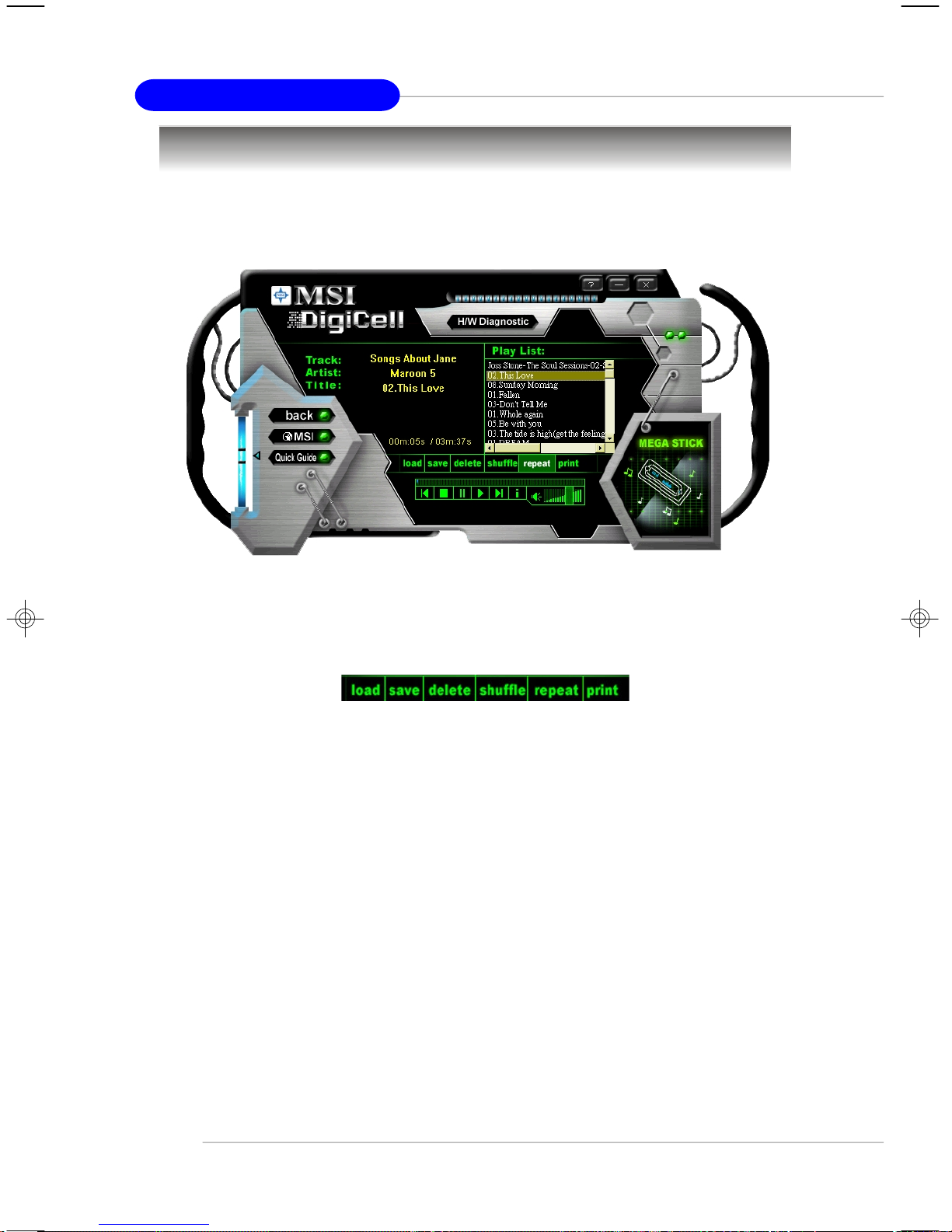
MS-7166 ATX Mainboard
MSI Feature
MEGA STICK
In the MEGA STICK sub-menu, you can configure the settings of MSI MEGA STICK
and the media files (*.m3u, *.mp3, *.wav, *.cda, *.wma) on your system.
Basic Function
Here you can edit your own play list with the buttons “load ”, “save”, “delete”,
“shuttle”, “ repeat” & “print”.
Load To load media files or the playlist of mp3 files (*.m3u) on your system or
on your MEGA STICK.
Save To save a loaded playlist of mp3 files (*.m3u) on your system or on
your MEGA STICK.
Delete Click on the media files in the Play List: field and use “ Delete” button
to remove the media file from the play list. You may remove multi media
files simultaneously by using “Ctrl” to select multi files.
Shuffle To play the media file in the Play List: in a random order.
Repeat To repeat the selected files in the Play List:.
Print This button has 2 functions:
1.To print out the details of current play list through your printer with
the following information:
Song title --- Song length --- Singer name
2.To save the details of current play list and save the file in the plain
text file format in the \\Program files\MSI\DigiCell\MyMusic.txt for
your reference. The MyMusic.txt file is with the following information:
Song title --- Song length --- Singer name
4-10
Page 75

Introduction to DigiCell
There is also a toolbar for you to execute some basic function, like play, stop, pause,
previous/next song, song info and volume adjust. There is also a scroll bar on the top
for you to forward/rewind.
previous
pause
next
forward/rewind
bar
song’s informationstop
play
Right-click on the MP3 file and choose “Info”, a MP3 Info dialogue
will pop up to show the information of the file, including the title, artist,
album, release year and others. You may also add your own comment
in the comment field. Then click “Save” to save the change, click
“Cancel” to discard the change, or click “Remove” to remove all
this information.
4-11
Page 76

MS-7166 ATX Mainboard
MSI Feature
Non-Unicode programs supported
If you are using an operating system in European languages, and you’ d like to play the
media files in MEGA STICK with East-Asian languages (such as Chinese, Japanese...
etc.), it is possible that the file names display incorrectly.
However, you can install the Supplemental Language Support provided by
Microsoft to solve this problem. You need to have your Microsoft Setup CD prepared
in the CD-ROM. The system will start to install the necessary components after the
settings are configured here. Follow the steps described below.
1.Go to [Control Panel] and choose [Regional and Languages Options].
2.Go to the [Languages] tab and enable the check box of [Install files for East
Asian languages]. A dialogue box will pop up to remind you the above selection
is chosen.
4-12
Page 77

Introduction to DigiCell
3. Then go to the [Advanced] tab and select the language you want to be
supported (the language of the filename in the MegaStick) from the drop-
down list in the [Language for non-Unicode programs], then click [Apply]. The
system will install the necessary components from your Microsoft Setup CD
immediately.
4-13
Page 78

MS-7166 ATX Mainboard
MSI Feature
Core Center (for Pentium 4 CPU)
Click on the Core Center icon in the main menu and the Core Center program will
be enabled.
CoreCenter is just like your PC doctor that can detect, view and adjust the PC
hardware and system status during real time operation.
In the left side it shows the current system status including the Vcore, 3.3V, +5V and
12V. In the right side it shows the current PC hardware status such as the CPU &
system temperatures and all fans speeds.
When you click the red triangles in the left and right sides, two sub-menus will open
for users to adjust the thresholds of system to send out the warning messages.
4-14
Page 79

Introduction to DigiCell
Left-wing: Current system status
In the left sub-menu, you can configure the settings of FSB, Vcore, Memory Voltage
and AGP Voltage by clicking the radio button next to each item and make it available
(the radio button will be lighted as yellow when selected), use the “+” and “-” buttons
to adjust, then click “OK” to apply the changes. Then you can click “Save” to save
the values you just configured.
Also you may click “Auto” to start testing the maximum CPU overclocking value. The
CPU FSB will automatically increase the testing value until the PC reboots. Or you may
click “Default” to restore the default values.
Right-wing: PC hardware status during real time operation
In the right sub-menu, here you can configure the PC hardware status such as CPU
& system temperatures and fan speeds. You may use the scroll bars to adjust each
item, then click “OK” to apply the changes. The values you set for the temperatures
are the maximum thresholds for the system for warnings, and the value for fan
speeds are the minimum thresholds.
4-15
Page 80

MS-7166 ATX Mainboard
MSI Feature
Audio Speaker Setting
In the Audio Speaker Setting sub-menu, you can configure the multi-channel audio
operation, perform speaker test, and choose the environment you prefer while enjoying the music.
You can scroll the bar of each equalizer to regulate the current playing digital sound
source. Also you may click on the “on” button to enable/disable the equalizer function.
Once the equalizer function is enabled, you can choose several preset equalizers
for your preference. You may also right-click anywhere to execute this function.
After you have chosen one equalizer, it will be indicated next to the “ on” button in
yellow.
The Environment setting lets you select the environment you like, such as
Cave or Convert Hall .
4-16
Page 81

Introduction to DigiCell
Click on the “Speaker test” button and the following dialogue box will appear:
In this Speaker Configuration dialogue box, select the audio configuration which
is identical to the audio jack on your mainboard. Once the correct audio configuration
is selected, click “Apply ” to save the changes. Then the following screen will
appear. In this Speaker Configuration dialogue box, first select the correct item
from the Speaker mode drop-down list, and then click on each connected speaker
to ensure if Headphone, 2-, 4-, 5.1-, or 7.1- channel audio operation is working
properly. If any speaker fails to make sound, then check whether the cable is inserted firmly to the connector, or replace the bad speakers with good ones.
Front Left
Main Side Left
Rear Left
Center
Front Right
Main Side Right
Rear Right
Subwoofer
4-17
Page 82

MS-7166 ATX Mainboard
MSI Feature
Power on Agent
In the Power on Agent sub-menu, you can configure setting of power-on, power-
off and restarting status.
In the screen below, you can set the date, time, start-up programs respectively for
power-on, power-off and restarting.
Power On
Here are the available settings for Power On function:
Date Use the drop-down list to select the date for power-on.
Time Use the arrow keys to select the hour/minute/second for power-on,
power-off and restarting. Then click “Apply” to save the changes. As
you click “Apply ”, the following dialogue will appear to show you the
next power-on schedule, and the system will start to count down to
restart. Click “OK” to restart the computer right away or click “Later ”
to restart your computer later.
MSI Reminds You...
Please note that the new setting will not take effect until you restart your
computer.
4-18
Page 83

Introduction to DigiCell
Power Off / Restart
You may configure the time (in the format hh:mm:ss) for the next power-off / restart.
Start With
Use the button “ +Add” to add the start-up programs
as DigiCell is activated next time. For example, you
may like to have Outlook activated or a specified
website linked when you get to the office every
morning.
Step 1: Click on the Program: field and click “>>”
button to browse for the path of Outlook or
Internet Explorer.
Step 2: Click on “OK” to apply the setting.
Step 3: For specified file or specified website, you
may enter the file name with the complete
path or the website link in the Parameters: field.
add the desired startwith program
To activate Outlook as DigiCell
is enabled next time
To activate a specified website
as DigiCell is enabled next time
Of course you may use the button “-Delete” to remove the added programs, or you
can right-click on the selected program and click Delete.
delete the added program
MSI Reminds You...
You can also enable the Every turn on function, which will enable the
specified program(s) and file(s) every time the Digi Cell utility runs.
4-19
Page 84

MS-7166 ATX Mainboard
MSI Feature
Auto Login
Since the Power On function allows the system to power on automatically, you may
have to enable this Auto Login function in the following situations:
1.If you are using a computer belonging to a domain in office, and you need to
enter your user name & password everytime when you boot up your computer.
2.If there are multi users using the same computer and you’ d like to power on the
computer automatically with one specific user.
Enable Auto Login
Enable this setting if you want to use the Auto Login feature. It supports the
following operating systems: Win9X, Windows ME, Windows 2000 & Windows XP.
Default User Name
It is only available for Windows 2000 & Windows XP.
--If you are using a computer belonging to a domain in office, please enter your
login user name in this field.
--If you are using a computer with multi users (for Windows XP operating system),
please enter the user name you’d like to auto power-on in this field.
Default Password
It is only available for Windows 2000 & Windows XP.
--If you are using a computer belonging to a domain in office, please enter your
login password in this field.
--If you are using a computer with multi-users (for Windows XP operating system),
please enter the password for the user name you’d like to auto power-on in
this field.
4-20
Page 85

Introduction to Intel ICH6R SATA RAID
Chapter 5. Intel ICH6R RAID
Introduction
Introduction to Intel
ICH6R SATA RAID
The optional southbridge ICH6R provides a hybrid solution that combines four independent SATA ports for support of up to four Serial ATA
(Serial ATA RAID) drives.
Serial ATA (SATA) is the latest generation of the ATA interface. SATA
hard drives deliver blistering transfer speeds up to 150MB/sec. Serial ATA
uses long, thin cables, making it easier to connect your drive and improving
the airflow inside your PC. The most outstanding features are:
1. Supports 150 MB/s transfers with CRC error checking.
2. Supports Hot-plug-n-play feature.
3. Data handling optimizations including tagged command queuing,
elevator seek and packet chain command.
Intel ICH6R includes the RAID level 0 (striping), RAID level 1
(mirroring), and a combination of the two called Intel Matrix RAID Technology,
which has two volume in two hard disk.
RAID 0 breaks the data into blocks which are written to separate
hard drives. Spreading the hard drive I/O load across independent channels greatly improves I/O performance. RAID 1 provides data redundancy
by mirroring data between the hard drives and provides enhanced read
performance. Intel Matrix RAID Technology is the advanced ability for two
RAID volumes to share the combined space of two hard drives being used
in unison.
MSI Reminds You...
The maximum number of hard drives for RAID 0, RAID 1 or Matrix mode
is 2.
All the information/volumes listed in your system might differ from the
illustrations in this appendix.
5-1
Page 86

MS-7166 ATX Mainboard
BIOS Configuration
The Intel RAID Option ROM should be integrated with the system BIOS on all
motherboards with a supported Intel chipset. The Intel RAID Option ROM is the Intel
RAID implementation and provides BIOS and DOS disk services. Please use <Ctrl> +
<I> keys to enter the “ Intel(R) RAID for Serial ATA” status screen, which should
appear early in system boot-up, during the POST (Power-On Self Test). Also, you
need to enable the RAID function in BIOS (please to P.3-14 items Onboard RAID
control <Enhanced> & Configure SATA as <RAID> for details) to create, delete
and reset RAID volumes.
Using the Intel RAID Option ROM
1. Creating, Deleting and Resetting RAID Volumes:
The Serial ATA RAID volume may be configured using the RAID Configuration
utility stored within the Intel RAID Option ROM. During the Power-On Self Test (POST),
the following message will appear for a few seconds:
MSI Reminds You...
The “Driver Model”, “Serial #” and “Size” in the following example might
be different from your system.
After the above message shows, press <Ctrl> and <I> keys simultaneously
to enter the RAID Configuration Utility.
MSI Reminds You...
The following procedure is only available with a newly-built system or if
you are reinstalling your OS. It should not be used to migrate an existing system to RAID 0 or RAID 1.
5-2
Page 87

After pressing the <Ctrl> and <I> keys simultaneously, the following window
will appear:
Introduction to Intel ICH6R SATA RAID
(1) Create RAID Volume
1. Select option 1 “Create RAID Volume” and press <Enter> key. The following
screen appears. Then in the Name field, specify a RAID Volume name and
then press the <TAB> or <Enter> key to go to the next field.
2. Use the arrow keys to select the RAID level (RAID0 or RAID1) best suited to
your usage model in RAID Level.
5-3
Page 88
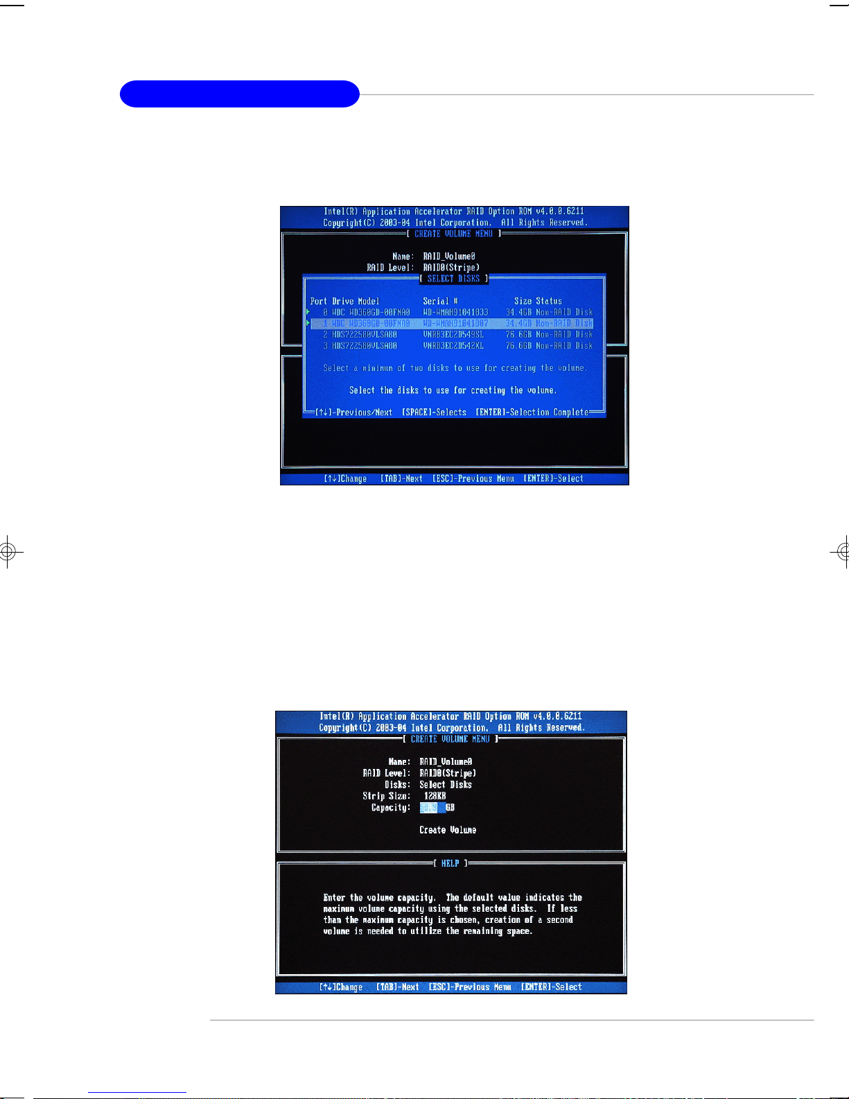
MS-7166 ATX Mainboard
3. In the Disk field, press <Enter> key and the following screen appears. Use
<Space> key to select the disks you want to create for the RAID volume, then
click <Enter> key to finish selection.
4. Then select the strip value for the RAID 0 or RAID 1 array by using the “upper
arrow” or “down arrow” keys to scroll through the available values, and
pressing the <Enter> key to select and advance to the next field. The available values range from 4KB to 128 KB in power of 2 increments. The strip
value should be chosen based on the planned drive usage. Here are some
suggested selections:
16 KB – Best for sequential transfers
64 KB – Good general purpose strip size
128 KB – Best performance for most desktops and workstations. The default
value.
5. Then select the capacity of the volume in the Capacity field. The default
value is the maximum volume capacity of the selected disks.
5-4
Page 89

Introduction to Intel ICH6R SATA RAID
MSI Reminds You...
Since you want to create two volumes (Intel Matrix RAID Technology),
this default size (maximum) needs to be reduced. Type in a new size for
the first volume. As an example: if you want the first volume to span the
first half of the two disks, re-type the size to be half of what is shown by
default. The second volume, when created, will automatically span the
remainder of two hard drives.
6.Then the following screen appears for you to confirm if you are sure to
create the RAID volume. Press <Y> to continue.
7.Then the following screen appears to indicate that the creation is finished.
5-5
Page 90
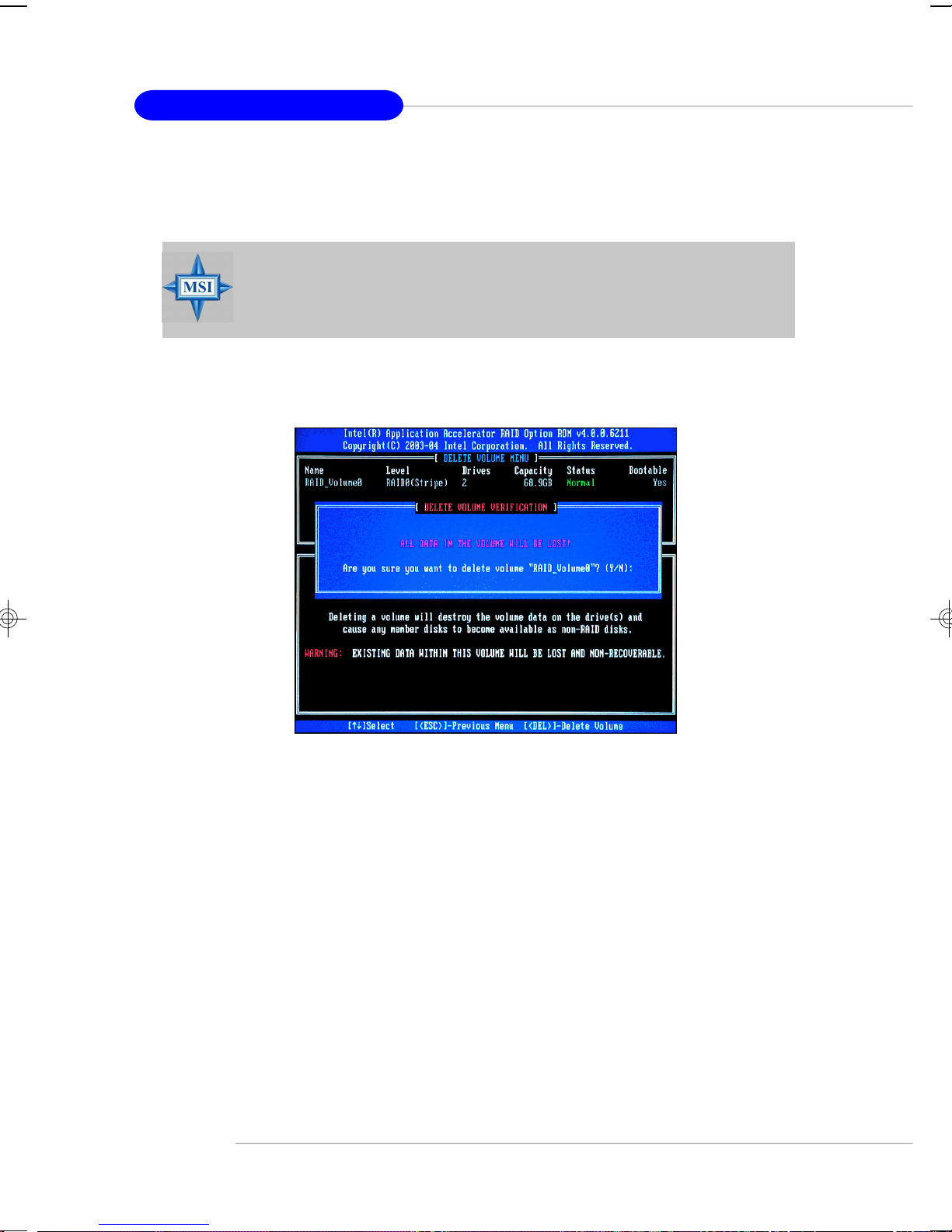
MS-7166 ATX Mainboard
(2) Delete RAID Volume
Here you can delete the RAID volume, but please be noted that all data on RAID
drives will be lost.
MSI Reminds You...
If your system currently boots to RAID and you delete the RAID volume
in the Intel RAID Option ROM, your system will become unbootable.
Select option 2 Delete RAID Volume from the main menu window and press
<Enter> key to select a RAID volume for deletion. Then press <Delete> key to delete
the selected RAID volume. The following screen appears.
Press <Y> key to accept the volume deletion.
5-6
Page 91

Introduction to Intel ICH6R SATA RAID
(3) Reset Disks to Non-RAID
Select option 3 Reset Disks to Non-RAID and press <Enter> to delete the RAID
volume and remove any RAID structures from the drives. The following screen
appears:
Press <Y> key to accept the selection.
MSI Reminds You...
1. You will lose all data on the RAID drives and any internal RAID
structures when you perform this operation.
2. Possible reasons to ‘Reset Disks to Non-RAID’ could include issues
such as incompatible RAID configurations or a failed volume or
failed disk.
5-7
Page 92

MS-7166 ATX Mainboard
Installing Software
Install Driver in Windows XP / 2000
† New Windows XP / 2000 Installation
The following details the installation of the drivers while installing Windows XP /
2000.
1. Start the installation:
Boot from the CD-ROM. Press F6 when the message "Press F6 if you need
to install third party SCSI or RAID driver" appears.
2. When the Windows XP Setup window is generated, press S to specify an
Additional Device(s).
3. Insert the driver diskette Intel IAA RAID XP Driver For ICH6R (FW82801FR)
into drive A: and press <Enter>.
4. Choose the driver Intel(R) 82801FR SATA RAID Controller from the drop-
down list that appears on Windows XP Setup screen, and press the <Enter>
key.
5. Press <Enter> to continue with installation or if you need to specify any
additional devices to be installed, do so at this time. Once all devices are
specified, press <Enter> to continue with installation.
6. From the Windows XP/2000 Setup screen, press the <Enter> key. Setup will
now load all device files and then continue the Windows XP/2000 installation.
† Existing Windows XP/2000 Driver Installation
1. Insert the MSI CD into the CD-ROM drive.
2. The CD will auto-run and the setup screen will appear.
3. Under the Driver tab, click on Intel IAA RAID Edition.
4. The drivers will be automatically installed.
† Confirming Windows XP/2000 Driver Installation
1. From Windows XP/2000, open the Control Panel from My Computer fol-
lowed by the System icon.
2. Choose the Hardware tab, then click the Device Manager tab.
3. Click the "+" in front of the SCSI and RAID Controllers hardware type. The
driver Intel(R) 82801FR SATA RAID Controller should appear.
5-8
Page 93
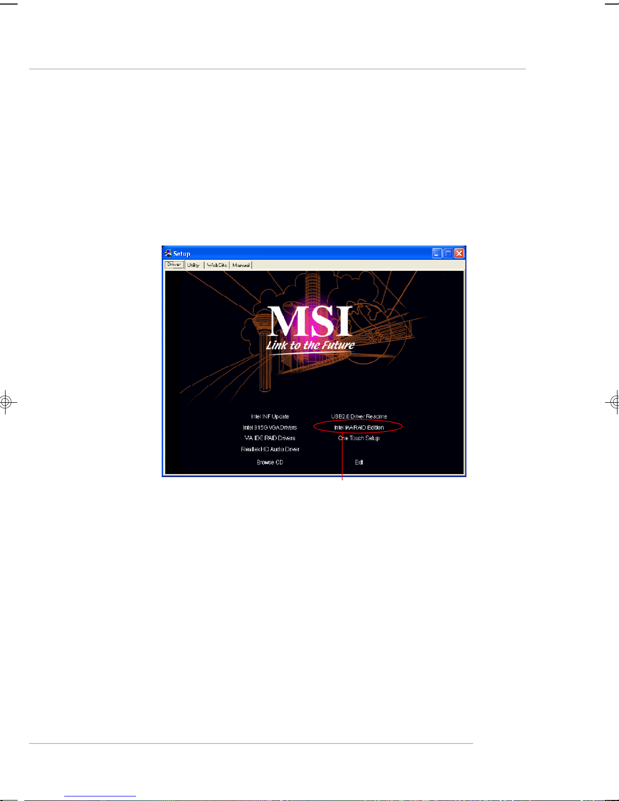
Introduction to Intel ICH6R SATA RAID
Installation of Intel Application Accelerator RAID Edition
The Intel Application Accelerator RAID Edition driver may be used to operate
the hard drive from which the system is booting or a hard drive that contains important data. For this reason, you cannot remove or un-install this driver from the system
after installation; however, you will have the ability to un-install all other non-driver
components.
Insert the MSI CD and click on the Intel IAA RAID Edition to install the software.
Click on this item
5-9
Page 94

MS-7166 ATX Mainboard
The InstallShield Wizard will begin automatically for installation showed as
following:
Click on the Next button to proceed the installation in the welcoming window.
5-10
Page 95
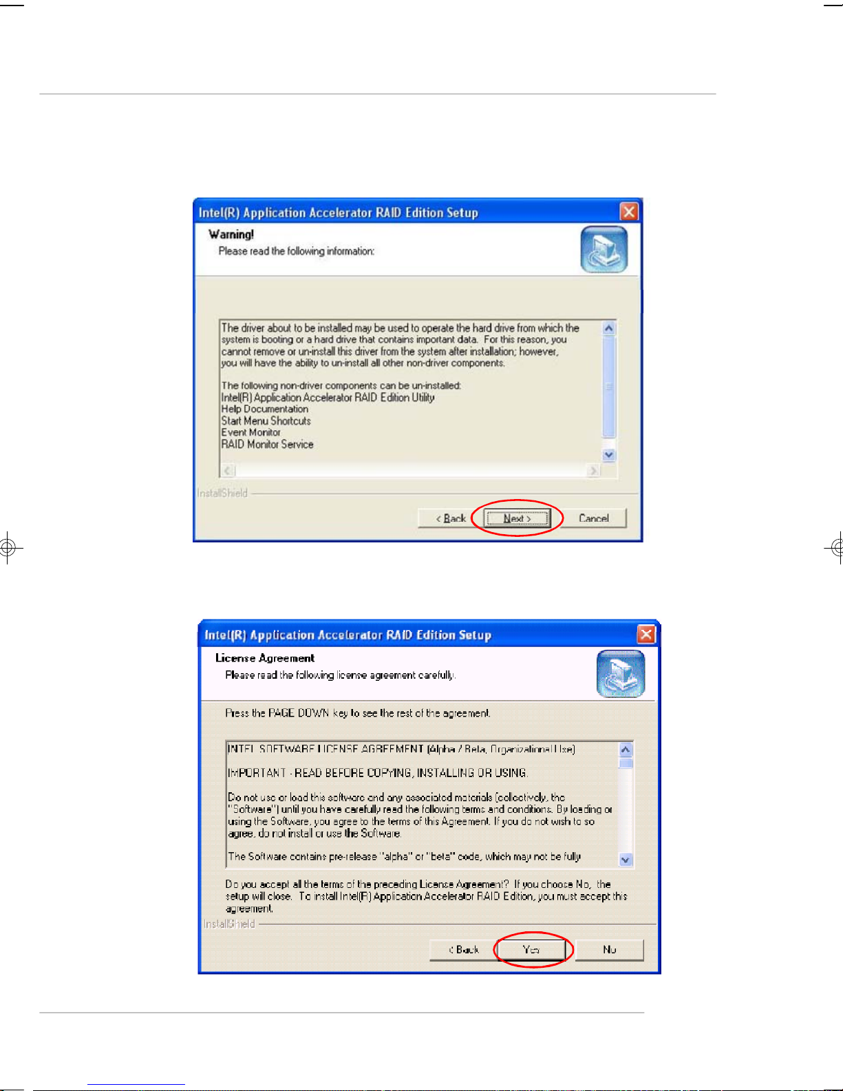
Introduction to Intel ICH6R SATA RAID
The window shows the components to be installed. Click Next button to continue.
After reading the license agreement in the following window, click Yes button to
continue.
5-11
Page 96

MS-7166 ATX Mainboard
Select the folder in which you want the program to be installed in the following
window, and click Next button to start installation.
Select a program folder in the following window where you want Setup to add the
program icon.
5-12
Page 97

Introduction to Intel ICH6R SATA RAID
The following window appears to show the Intel Application Accelerator RAID
Edition Setup installation status.
Once the installation is complete, the following window appears.
5-13
Page 98

MS-7166 ATX Mainboard
RAID Migration Instructions
The Intel Application Accelerator RAID Edition offers the flexibility to upgrade
from a single Serial ATA (SATA) hard drive to a two drive RAID 0 or RAID 1 configuration when an additional SATA hard drive is added to the system. This process will
create a new RAID volume from an existing disk. However, several important steps
must be followed at the time the system is first configured in order to take advantage
of RAID when upgrading to a second SATA hard drive:
1. BIOS must be configured for RAID before installing Windows* XP on the
single SATA hard drive. Refer to P.3-16 On Chip SATA Setting for
properly setting of the BIOS.
2. Install the Intel Application Accelerator RAID Driver during Windows Setup.
Refer to P.5-8 Installing Software for instructions on installing the
driver during Windows Setup.
3. Install the Intel Application Accelerator RAID Edition after the operating
system is installed.
To create a volume from an existing disk, complete the following steps:
MSI Reminds You...
A Create from Existing Disk operation will delete all existing data
from the added disk and the data cannot be recovered. It is critical to
backup all important data on the added disk before proceeding. However,
during the migration process, the data on the source disk is preserved.
After the Intel Application Accelerator RAID Edition has been successfully
installed and the system has rebooted, click on the Intel Application Accelerator
shortcut link (Start --> All Programs --> Intel(R) Application Accelerator -->
Intel Application Accelerator) and the following window will appear:
5-14
Page 99

Introduction to Intel ICH6R SATA RAID
Create RAID Volume from Existing Disk
To create a RAID volume from an existing disk, choose Action --> Create
RAID Volume from Existing Hard Drive.
The Create RAID Volume from Existing Hard Drive Wizard pops up to lead
you for the following procedure. Click Next to continue.
5-15
Page 100

MS-7166 ATX Mainboard
(1) Step 1: Configure Volume
Here you can configure the new RAID volume by entering the volume name,
selecting the RAID level and strip size.
† RAID Volume Name:
A desired RAID volume name needs to be typed in where the ‘RAID_Volume1’ text
currently appears above. The RAID volume name has a maximum limit of 16 characters.
The RAID volume name must also be in English alphanumeric ASCII characters.
† RAID Level:
Select the desired RAID level:
RAID 0 (Performance) – A volume optimized for performance will allow you to
access your data more quickly.
RAID 1 (Redundancy) – A volume optimized for data redundancy will provide
you with a realtime duplicate copy of your data. Note:
Only half of the available volume space will be available for data storage.
† Strip Sizes:
Select the desired strip size setting. As indicated, the optimal setting is 128KB. Selecting any other option may result in performance degradation. Even though 128KB
is the recommended setting for most users, you should choose the strip size value
which is best suited to your specific RAID usage model. The most typical strip size
settings are:
4KB: For specialized usage models requiring 4KB strips
8KB: For specialized usage models requiring 8KB strips
16KB: Best for sequential transfers
32KB: Good for sequential transfers
64KB: Good general purpose strip size
128KB: Best performance for most desktops and workstations
5-16
 Loading...