

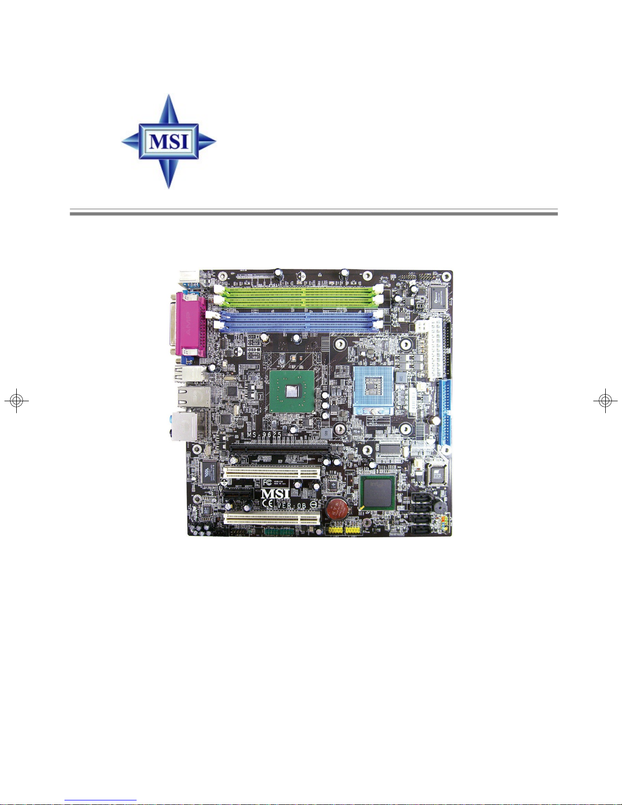
915GM Speedster
MS-9625 (v1.X) Workstation Board
English Version
G52-S9625X1
i

Copyright Notice
The material in this document is the intellectual property of MICRO-STAR
INTERNATIONAL. We take every care in the preparation of this document, but no
guarantee is given as to the correctness of its contents. Our products are under
continual improvement and we reserve the right to make changes without notice.
Trademarks
All trademarks are the properties of their respective owners.
Intel® and Pentium® are registered trademarks of Intel Corporation.
AMD, Athlon™ , Athlon™ XP, Thoroughbred™, and Duron™ are registered trademarks of AMD Corporation.
PS/2 and OS®/2 are registered trademarks of International Business Machines
Corporation.
Windows® 95/98/2000/NT/XP are registered trademarks of Microsoft Corporation.
Netware® is a registered trademark of Novell, Inc.
Award® is a registered trademark of Phoenix Technologies Ltd.
AMI® is a registered trademark of American Megatrends Inc.
Revision History
Revision Revision History Date
V1.0 First release August 2005
Technical Support
If a problem arises with your system and no solution can be obtained from the user’s
manual, please contact your place of purchase or local distributor. Alternatively,
please try the following help resources for further guidance.
Visit the MSI website for FAQ, technical guide, BIOS updates, driver updates,
and other information: http://www.msi.com.tw/program/service/faq/
faq/esc_faq_list.php
Contact our technical staff at: support@msi.com.tw
ii
Safety Instructions
1. Always read the safety instructions carefully.
2. Keep this User’s Manual for future reference.
3. Keep this equipment away from humidity.
4. Lay this equipment on a reliable flat surface before setting it up.
5. The openings on the enclosure are for air convection hence protects the equipment from overheating. DO NOT COVER THE OPENINGS.
6. Make sure the voltage of the power source and adjust properly 110/220V before connecting the equipment to the power inlet.
7. Place the power cord such a way that people can not step on it. Do not place
anything over the power cord.
8. Always Unplug the Power Cord before inserting any add-on card or module.
9. All cautions and warnings on the equipment should be noted.
10. Never pour any liquid into the opening that could damage or cause electrical
shock.
11. If any of the following situations arises, get the equipment checked by a service
personnel:
† The power cord or plug is damaged.
† Liquid has penetrated into the equipment.
† The equipment has been exposed to moisture.
† The equipment has not work well or you can not get it work according to
User’s Manual.
† The equipment has dropped and damaged.
† The equipment has obvious sign of breakage.
12. DO NOT LEAVE THIS EQUIPMENT IN AN ENVIRONMENT UNCONDITIONED, STORAGE TEMPERATURE ABOVE 600 C (1400F), IT MAY DAMAGE THE EQUIPMENT.
CAUTION: Danger of explosion if battery is incorrectly replaced.
Replace only with the same or equivalent type recommended by the
manufacturer.
iii
FCC-B Radio Frequency Interference Statement
This equipment has been
tested and found to comply
with the limits for a Class B
digital device, pursuant to Part
15 of the FCC Rules. These limits are designed to provide reasonable protection
against harmful interference in a residential installation. This equipment generates,
uses and can radiate radio frequency energy and, if not installed and used in accordance with the instructions, may cause harmful interference to radio communications.
However, there is no guarantee that interference will not occur in a particular
installation. If this equipment does cause harmful interference to radio or television
reception, which can be determined by turning the equipment off and on, the user is
encouraged to try to correct the interference by one or more of the measures listed
below.
† Reorient or relocate the receiving antenna.
† Increase the separation between the equipment and receiver.
† Connect the equipment into an outlet on a circuit different from that to
which the receiver is connected.
† Consult the dealer or an experienced radio/television technician for help.
Notice 1
The changes or modifications not expressly approved by the party responsible for
compliance could void the user’s authority to operate the equipment.
Notice 2
Shielded interface cables and A.C. power cord, if any, must be used in order to
comply with the emission limits.
VOIR LA NOTICE D’ INSTALLATION AVANT DE RACCORDER AU RESEAU.
Micro-Star International
MS-9625
This device complies with Part 15 of the FCC Rules. Operation is subject to the
following two conditions:
(1) this device may not cause harmful interference, and
(2) this device must accept any interference received, including interference that
may cause undesired operation.
iv
WEEE (Waste Electrical and Electronic Equipment) Statement
v
vi
vii

CONTENTS
Copyright Notice..............................................................................................................ii
Trademarks.......................................................................................................................ii
Revision History..............................................................................................................ii
Technical Support...........................................................................................................ii
Safety Instructions..........................................................................................................iii
FCC-B Radio Frequency Interference Statement........................................................iv
WEEE (Waste Electrical and Electronic Equipment) Statement....................................v
Chapter 1. Getting Started....................................................................................1-1
Mainboard Specifications...................................................................................1-2
Mainboard Layout................................................................................................1-4
MSI Special Features..........................................................................................1-5
Core Center (Optional)................................................................................1-5
Chapter 2. Hardware Setup..................................................................................2-1
Quick Components Guide....................................................................................2-2
Central Processing Unit: CPU.............................................................................2-3
CPU and Cooler Set Installation..................................................................2-4
Memory.................................................................................................................2-6
Installing DDR Modules................................................................................2-6
Memory Population Rules............................................................................2-7
Power Supply......................................................................................................2-8
SSI 24-Pin System Power Connector: ATX1.............................................2-8
SSI 8-Pin CPU Power Connector: JPW1....................................................2-8
Back Panel............................................................................................................2-9
Mouse Connector (Green) / Keyboard Connector (Purple)....................2-9
VGA Port.......................................................................................................2-9
Serial Port...................................................................................................2-10
USB Connectors........................................................................................2-10
LAN (RJ-45) Jacks......................................................................................2-11
Audio Port Connectors...............................................................................2-11
Parallel Port Connector: LPT1...................................................................2-13
Connectors........................................................................................................2-13
Floppy Disk Drive Connector: FDD1..........................................................2-13
Hard Disk Connector: IDE1........................................................................2-13
Serial ATA Connectors: SATA1, SATA2, SATA3, SATA4.......................2-14
Front Panel Audio Connector: JAUD1......................................................2-15
Chassis Intrusion Switch Connector: JCI1..............................................2-16
viii

CD-In Connector: JCD1.............................................................................2-16
Front Panel Connector: JFP1....................................................................2-16
Fan Power Connectors: CPUFAN1, SYSFAN1.......................................2-17
IEEE 1394 Connectors: J1394_1, J1394_2.............................................2-17
Front USB Connectors: F_USB1, F_USB2.............................................2-18
Serial Port Header: COM2.........................................................................2-18
Jumper................................................................................................................2-19
Clear CMOS Jumper: CLR_CMOS1..........................................................2-19
FSB Frequency Jumpers: J4, J5..............................................................2-20
CPU VCCA Jumper: J6..............................................................................2-21
GMCH Voltage Jumper: J3.........................................................................2-21
Slots....................................................................................................................2-22
PCI (Peripheral Component Interconnect) Express Slots.......................2-22
PCI (Peripheral Component Interconnect) Slots......................................2-22
PCI Interrupt Request Routing...................................................................2-23
Chapter 3. BIOS Setup............................................................................................3-1
Entering Setup.....................................................................................................3-2
Control Keys................................................................................................3-2
Getting Help..................................................................................................3-3
General Help <F1>.......................................................................................3-3
The Menu Bar.......................................................................................................3-4
Main......................................................................................................................3-5
Advanced............................................................................................................3-6
Security..............................................................................................................3-16
Server................................................................................................................3-17
Boot....................................................................................................................3-19
Exit......................................................................................................................3-20
Appendix A: Realtek ALC880 8-Channel Audio Function.............................A-1
Installing the Realtek HD Audio Driver................................................................A-2
Installation for Windows 2000/XP..............................................................A-2
Software Configuration......................................................................................A-4
Sound Effect................................................................................................A-5
Mixer.............................................................................................................A-8
Audio I/O.....................................................................................................A-13
Microphone................................................................................................A-18
3D Audio Demo...........................................................................................A-19
Information..................................................................................................A-20
ix

Using 2-, 4-, 6- & 8- Channel Audio Function.................................................A-22
Appendix B: Intel ICH6R SATA RAID (Optional).................................................B-1
BIOS Configuration..............................................................................................B-2
Using the Intel RAID Option ROM................................................................B-2
Installing Software..............................................................................................B-8
Install Driver in Windows XP / 2000...........................................................B-8
Installation of Intel Application Accelerator RAID Edition..........................B-9
RAID Migration Instructions...............................................................................B-14
Create RAID Volume from Existing Disk...................................................B-15
x

Getting Started
Chapter 1. Getting
Started
Getting Started
Thank you for choosing the 915GM Speedster (MS-9625 v1.X), an
excellent Micro ATX workstation board from MSI.
Based on the innovative Intel® 915GM & Intel® ICH6/ ICH6R chipsets
for optimal system efficiency, the 915GM Speedster mainboard accommodates the latest Intel® Pentium® M Dothan/ Celeron® M
Dothan processors in 478-pin package and supports up to two 184pin 333MHz non-ECC DDR DIMMs (or two 240-pin 400/533MHz nonECC DDR-II DIMMs) to provide the maximum of 2GB memory capacity.
In the entry-level and mid-range market segment, this mainboard can
provide a high-performance solution for today’s front-end and general purpose server/workstation, as well as in the future.
1-1

MS-9625 M-ATX Workstation Board
Mainboard Specifications
CPU
† Supports Intel® Pentium® M Dothan/ Celeron® M Dothan processors in 478-
pin package
† Up to 2MB L2 cache for Pentium® M Dothan and up to 1MB L2 cache for Celeron® M
Dothan
(For more information on compatible components, please visit http://www.msi.
com.tw/program/products/server/svr/pro_svr_qvl.php)
Chipset
† Intel® 915GM Northbridge
- Supports 400 and 533 MHz Intel® NetBurst micro-architecture bus
- PCI Express external graphics support
- Supports DDR333 or DDR-II 400/533 memory interface
- Integrated Intel® Graphics Media Accelerator (GMA) 900 with ADD2 interface
support
† Intel® ICH6 or ICH6R Southbridge
- Direct connection to GMCH via Direct Media Interface
- Supports one-channel Ultra ATA 100 bus Master IDE controller
- Two-port Serial ATA controller
- Support for up to eight USB 2.0 ports
- Intel® High Definition Audio interface
Main Memory
† Supports up to two 184-pin 333MHz non-ECC DDR DIMMs or two 240-pin
400/533MHz non-ECC DDR-II DIMMs
† Supports up to 2GB
(For more information on compatible components, please visit http://www.msi.
com.tw/program/products/server/svr/pro_svr_qvl.php)
Slots
† Two 32-bit/33MHz PCI slots (support 3.3V/5V PCI bus interface)
† One PCI Express x1 slot (PCI Express Bus specification v1.0a compliant)
† One PCI Express x16 slot (PCI Express Bus specification v1.0a compliant)
HDD Interface
† One IDE controller on the ICH6 / ICH6R chipset provides IDE HDD/CD-ROM with
PIO, Bus Master and Ultra DMA66/100 operation modes
† ICH6 / ICH6R chipset supports 4 Serial ATA 150 ports
Onboard Peripherals
† 1 floppy port supports one FDD with 360KB, 720KB, 1.2MB, 1.44MB, and 2.88MB
† 1 PS/2 keyboard port
† 1 PS/2 mouse port
† 1 serial port & 1 serial pinheader
1-2

Getting Started
† 1 VGA port
† 1 parallel port supports SPP/EPP/ECP mode
† 2 RJ-45 ports (with LEDs)
† 8 USB ports (4 on the front and 4 on the rear)
† 2 IEEE 1394 pinheaders
† 1 Line-In / Line-Out / MIC-In / Rear Speaker Out / Center-Subwoofer Speaker
Out / optical SPDIF-Out audio port
Onboard LAN
† 2 Marvell 88E8053 Gigabit Ethernet controllers
Onboard Audio
† High Definition Audio interface integrated in ICH6 / ICH6R
† Realtek ALC880 8-channel codec
- 8-CH DA connector with 48 KHz rate
- Compliant with AC97 2.3 specifications
- Meets perfomace requirement for audio on PC97/2001 system
- Meets Microsoft WHQL / WLP 2.0 audio requirement
Onboard IEEE 1394
† VIA VT6307 IEEE 1394 controller
Power Management Features
† Wake up on LAN (WOL), wake up on PCI
† RTC alarm and wake up
† Wake up on keyboard/mouse/USB from S1
† Supports ACPI S1, S3, S4, S5 function
System Management
† SMBus (I2C)
† Temperature, voltage, and fan monitors
BIOS
† The mainboard BIOS provides “Plug & Play” BIOS which detects the peripheral
devices and expansion cards of the board automatically
† The mainboard provides a Desktop Management Interface (DMI) function which
records your mainboard specifications
† Supports boot from LAN, USB Device 1.1 & 2.0, and SATA HDD
Dimension
† Micro ATX Form Factor: 24.5 cm (W) x 24.5 cm (L)
Mounting
† 8 mounting holes
1-3
MS-9625 M-ATX Workstation Board
BATT
FDD 1IDE
1
ATX1
Winbond
W83627THF
BIOSJ1J3
SATA1
CLR_CMOS1
ICH6/ICH6R
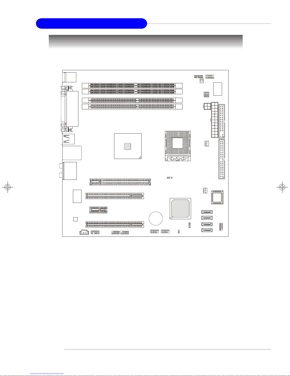
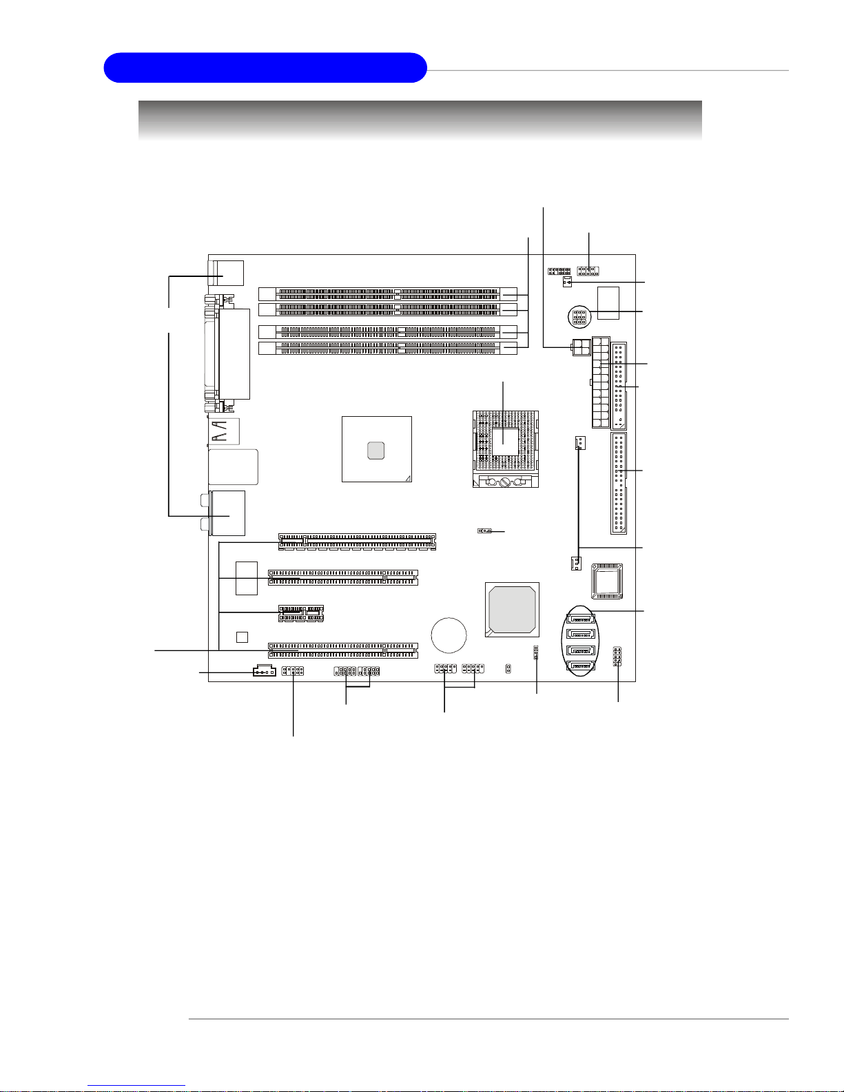
Mainboard Layout
Top: Mouse
Bottom: Keyboard
Top :
Parallel Port
Bottom:
COM
VGA Port
DIMM4
DIMM3
DIMM2
DIMM1
JLPC1
JCI1
COM2
J6J4J5
JPW1
USB Ports
LAN Jacks
T:
Line-In
M:
Line-Out
B:
Mic
T: RS-Out
M: CS-Out
B: SPDIFOut
VIA
VT6307
ALC880
JCD1
PCI _E1
PCI 2
PCI 1
JAUD1
PCI 3
J1394_1
Intel
915GM
J1394_2
+
F_USB2
F_USB1
Intel
CPUFAN1
SYSFAN1
SATA4
SATA3
SATA2
JFP1
915GM Speedster (MS-9625 v1.X) M-ATX Workstation Board
1-4
Getting Started
MSI Special Features
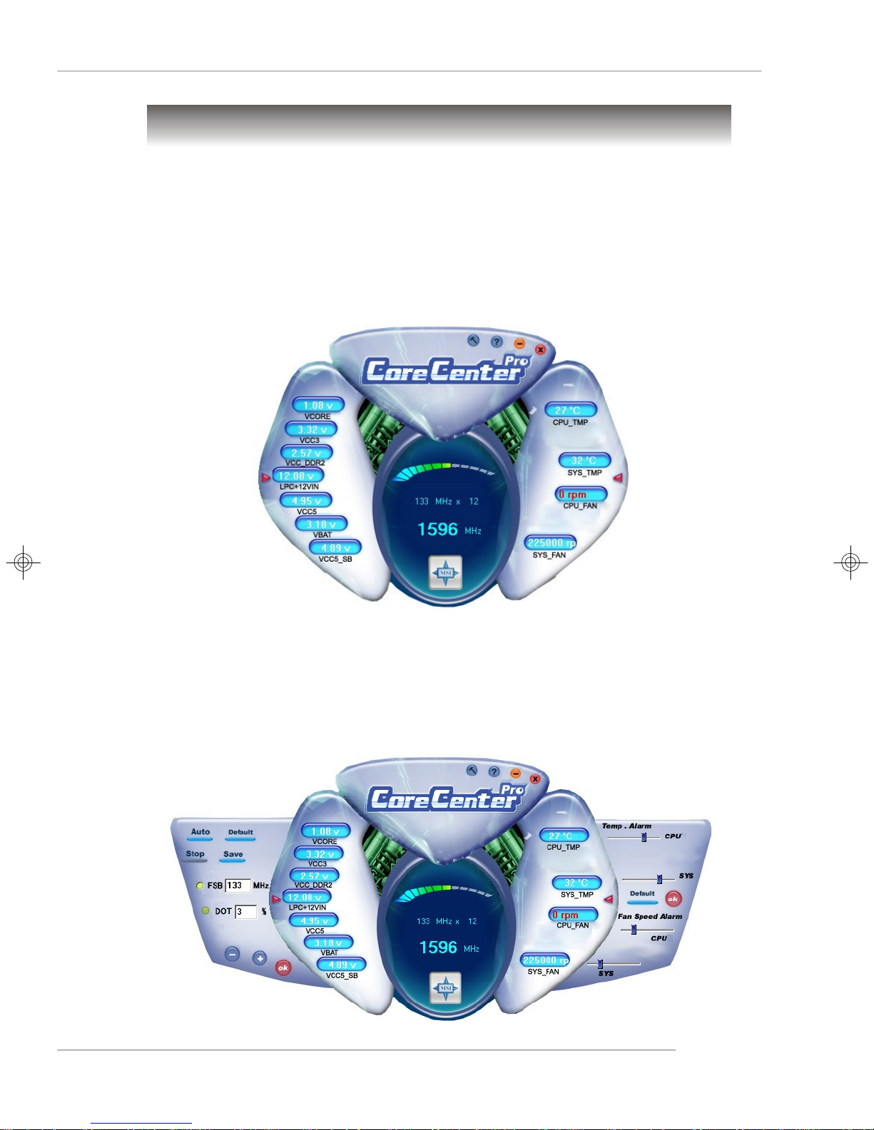
Core Center (Optional)
The Core Center is a new utility you can find in the CD-ROM disk. The utility is just like
your PC doctor that can detect, view and adjust the PC hardware and system status
during real time operation. In the left side it shows the current system status, including
the Vcore, 3.3V, +5V and 12V. In the right side it shows the current PC hardware
status such as the CPU & system temperatures and all fans speeds.
When you click the red triangles in the left and right sides, two sub-menus will open
for users to overclock, overspec or to adjust the thresholds of system to send out the
warning messages. If you click the Core Center button on the top, a screen pops up
for you to choose the “Auto mode” or “User mode” of CPU fan. You may adjust the
speeds of CPU fans and system fan here.
1-5

MS-9625 M-ATX Workstation Board
Left-side: Current system status
In the left sub-menu, you can configure the settings of FSB & DOT by clicking the radio
button in front of each item and make it available (the radio button will be lit as yellow
when selected), use the “+” and “-” buttons to adjust, then click “ok” to apply the
changes. Then you can click Save to save the desired FSB you just configured.
Also you may click Auto to start testing the maximal CPU overclocking value. The CPU
FSB will automatically increase the testing value until the PC reboots. Or you may click
Default to restore the default values.
Right-side: PC hardware status during real time operation
In the right sub-menu, here you can configure the PC hardware status such as CPU
& system temperatures and fan speeds. You may use the scroll bars to adjust each
item, then click “ok” to apply the changes. The values you set for the temperatures
are the maximum thresholds for the system for warnings, and the value for fan
speeds are the minimum thresholds.
Top-side: User mode/Auto mode
Here you may adjust the CPU fan speed. If you choose User mode, you may adjust
the CPU fan speed in 8 different modes, from Stop to Full speed.
MSI Reminds You...
Items shown on Core Center may vary depending on your system status.
1-6

Hardware Setup
Chapter 2. Hardware
Setup
Hardware Setup
This chapter provides you with the information about hardware setup
procedures. While doing the installation, be careful in holding the
components and follow the installation procedures. For some
components, if you install in the wrong orientation, the components
will not work properly.
Use a grounded wrist strap before handling computer components.
Static electricity may damage the components.
2-1
MS-9625 M-ATX Workstation Board
BIOS
Quick Components Guide
JPW1, p.2-8
I/O Ports,
p.2-9
PCI/PCI
Express Slots,
p.2-22
JCD1, p.2-16
DIMM4/3/2/1, p.2-6
CPU, p.2-3
J3, p.2-21
COM2, p.2-18
JCI1, p.2-16
J6/J4/J5,
p.2-20/21
ATX1, p.2-8
FDD1, p.2-13
IDE1, p.2-13
CPUFAN1/
SYSFAN1,
p.2-17
SATA4/
SATA3/
SATA2/
SATA1, p.2-14
JAUD1, p.2-15
2-2
J1394_1/2,
p.2-17
F_USB2/1,
p.2-18
CLR_CMOS1,
p.2-19
JFP1, p.2-16

Hardware Setup
Central Processing Unit: CPU
The mainboard supports Intel® Pentium® M Dothan/ Celeron® M Dothan processors in 478-pin package. The mainboard uses Socket 478 for easy CPU installation.
When you are installing the CPU, make sure the CPU has a heat sink and a
cooling fan attached on the top to prevent overheating. If you do not have the
heat sink and cooling fan, contact your dealer to purchase and install them before
turning on the computer.
For more information on compatible components, please visit http://www.msi.com.
tw/program/products/server/svr/pro_svr_qvl.php .
MSI Reminds You...
Overheating
Overheating will seriously damage the CPU and system, always make
sure the cooling fan can work properly to protect the CPU from overheating.
Overclocking
This motherboard is designed to support overclocking. However, please
make sure your components are able to tolerate such abnormal settings
while doing overclocking. Any attempt to operate beyond product
specifications is not recommended. We do not guarantee the
damages or risks caused by inadequate operation or beyond
product specifications.
2-3
MS-9625 M-ATX Workstation Board
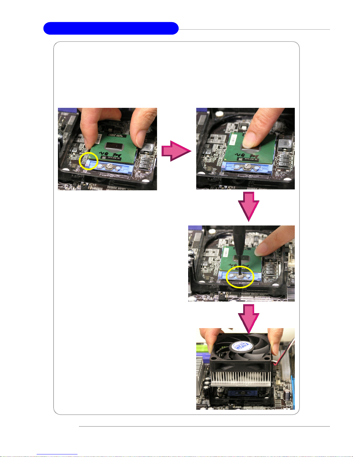
CPU & Cooler Set Installation
1. Place the CPU on top of the socket. Make sure to align the gold arrow on the CPU
with the arrow key on the socket.
2. Push the CPU down until its pins securely fit into the socket.
3. On the front end of the CPU socket is a
locking mechanism designed into the
form of a screw. Make sure that you
actuate or deactuate this mechanism with
a screwdriver before and after installing the CPU.
4. Mount the cooler set (fan & heatsink
bundled) on top of the CPU and fit it
into the retention mechanism.
2-4
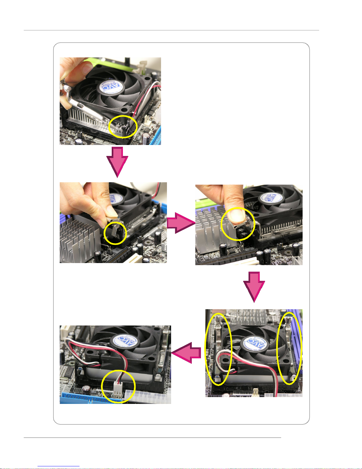
Hardware Setup
5. Secure one end of the metal clip to the
retention mechanism.
6. Hook the other end of the clip to the retention mechanism and press the lever
down to close.
7. Follow the same procedures to install
the second clip.
8. Connect the fan power cable from
the mounted fan to the 3-pin fan
power connector on the board.
2-5
MS-9625 M-ATX Workstation Board
Memory
The mainboard supports up to 2GB of DDR333 (two 184-pin 333MHz non-ECC DDR
DIMMs) or DDR-II 400/533 (two 240-pin 400/533MHz non-ECC DDR-II DIMMs) system
memory. Please note that only one type of memory (all DDR or all DDR-II, no mixture
allowed) can be used at one time.
For more information on compatible components, please visit http://www.msi.com.
tw/program/products/server/svr/pro_svr_qvl.php .
DIMM4 (DDR-II 400/533)
DIMM3 (DDR-II 400/533)
DIMM2 (DDR333)
DIMM1 (DDR333)
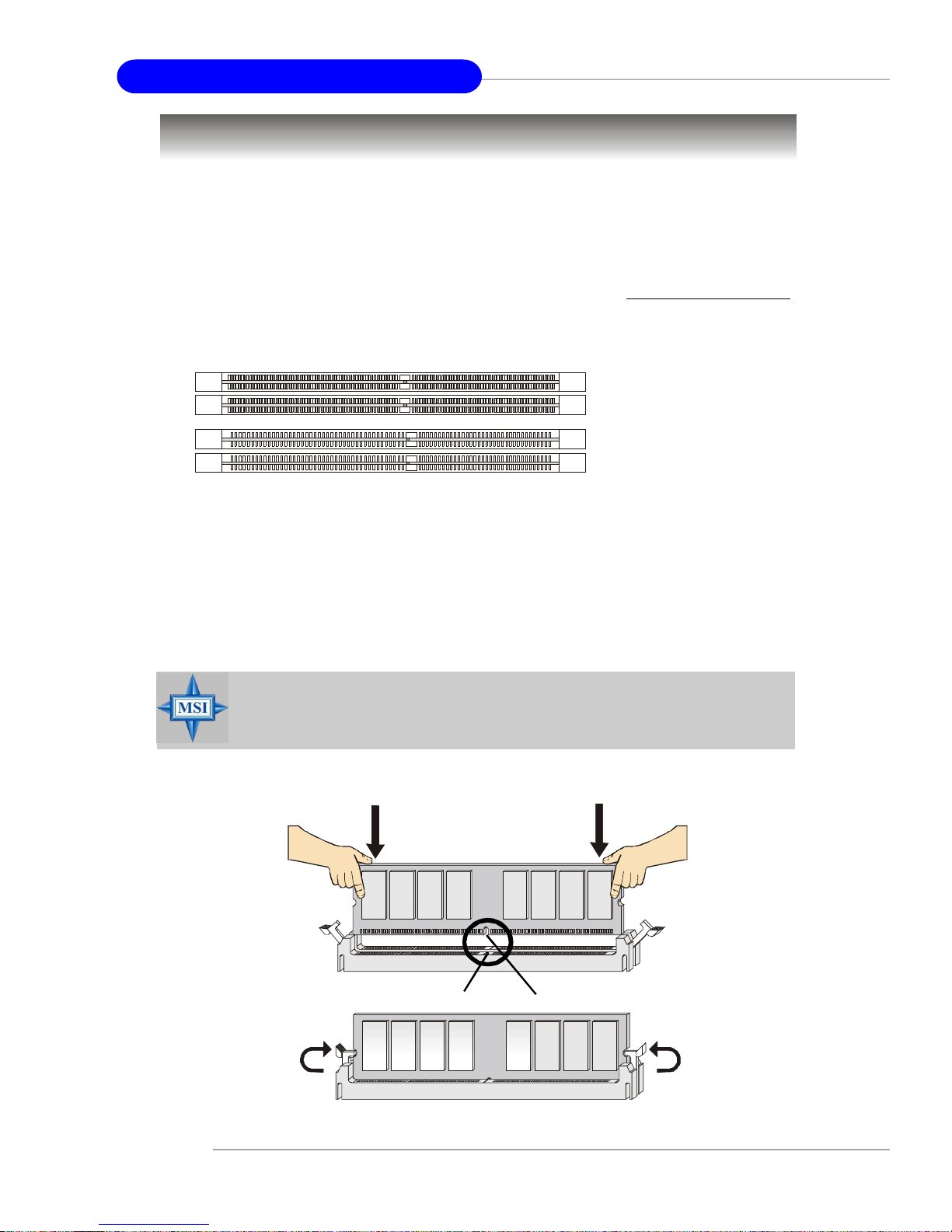
Installing DDR Modules
1. The DDR DIMM has only one notch on the center of module. The module will only fit
in the right orientation.
2. Insert the DIMM memory module vertically into the DIMM slot. Then push it in until the
golden finger on the memory module is deeply inserted in the socket.
MSI Reminds You...
You can barely see the golden finger if the module is properly inserted
in the socket.
3. The plastic clip at each side of the DIMM slot will automatically close.
Volt
Notch
2-6

Hardware Setup
Memory Population Rules
This mainboard supports DDR333 (DIMM1 & DIMM2) or DDR-II 400/533 (DIMM3 &
DIMM4) memory interface.
Each DIMM slot supports up to a maximum size of 1GB. Users can install either singleor double-sided modules depending on their needs. Please note that only one type of
memory (all DDR or all DDR-II, no mixture allowed) can be used at one time.
Slot Memory Module Total Memory
DIMM1 or DIMM3 S/D 64MB~1GB
DIMM2 or DIMM4 S/D 64MB~1GB
Maximum System Memory Supported 64MB~2GB
S: Single Side D: Double Side
MSI Reminds You...
Make sure that you install memory modules of the same type and
density on DDR DIMMs.
2-7

MS-9625 M-ATX Workstation Board
Power Supply
The mainboard supports SSI power supply for the power system. Before inserting
the power supply connector, always make sure that all components are installed
properly to ensure that no damage will be caused.
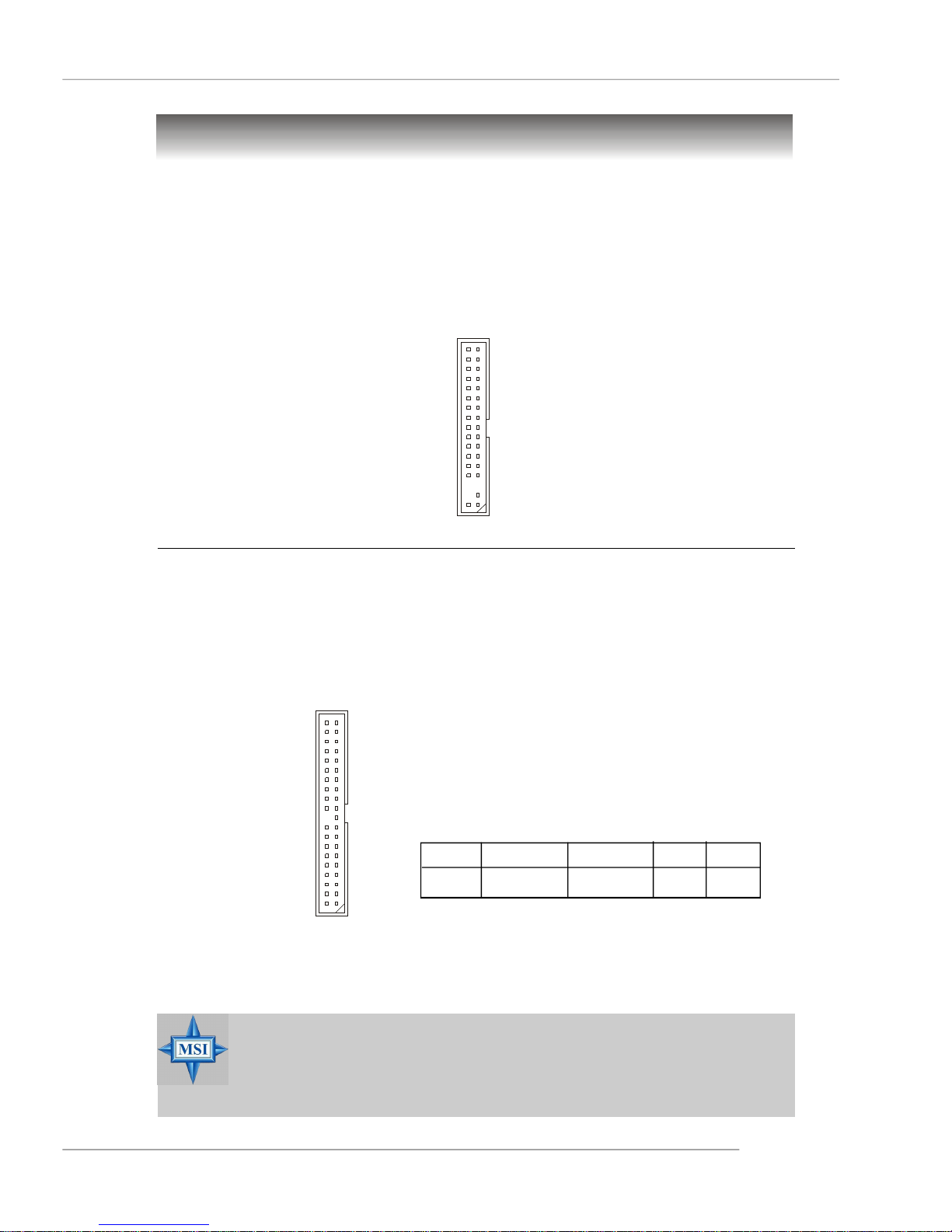
SSI 24-Pin System Power Connector: ATX1
pin 13
This connector allows you to connect an SSI power supply. To
connect the SSI power supply, make sure the plug of the power
supply is inserted in the proper orientation and the pins are aligned.
Then push down the power supply firmly into the connector.
You may use the 20-pin ATX power supply or 24-pin SSI power
supply as you like. If you’d like to use the ATX power supply,
pin 12
please plug your power supply along with pin 1 & pin 13 (refer to
the image at the right hand). There is also a foolproof design on pin 11, 12, 23 & 24 to
avoid wrong installation.
SSI 8-Pin CPU Power Connector: JPW1
This connector provides 12V power output to the CPU.
24
13
ATX1
1
12
ATX1 Pin Definition
PIN SIGNAL
1 +3.3V
2 +3.3V
3 GND
4 +5V
5 GND
6 +5V
7 GND
8 PWR OK
9 5VSB
10 +12V
11 +12V
12 NC
PIN SIGNAL
13 +3.3V
14 -12V
15 GND
16 PS-ON#
17 GND
18 GND
19 GND
20 Res
21 +5V
22 +5V
23 +5V
24 GND
4
3
2
1
JPW1
JPW1 Pin Definition
PIN SIGNAL
1 GND
2 GND
3 12V
4 12V
MSI Reminds You...
1. Maker sure that these two connectors are connected to adequate SSI
power supplies to ensure stable operation of the mainboard.
2. Power supply of 350watts (and above) is highly recommended for
system stability.
3. SSI 12V power connection should be greater than 18A.
2-8
Mouse
Parallel
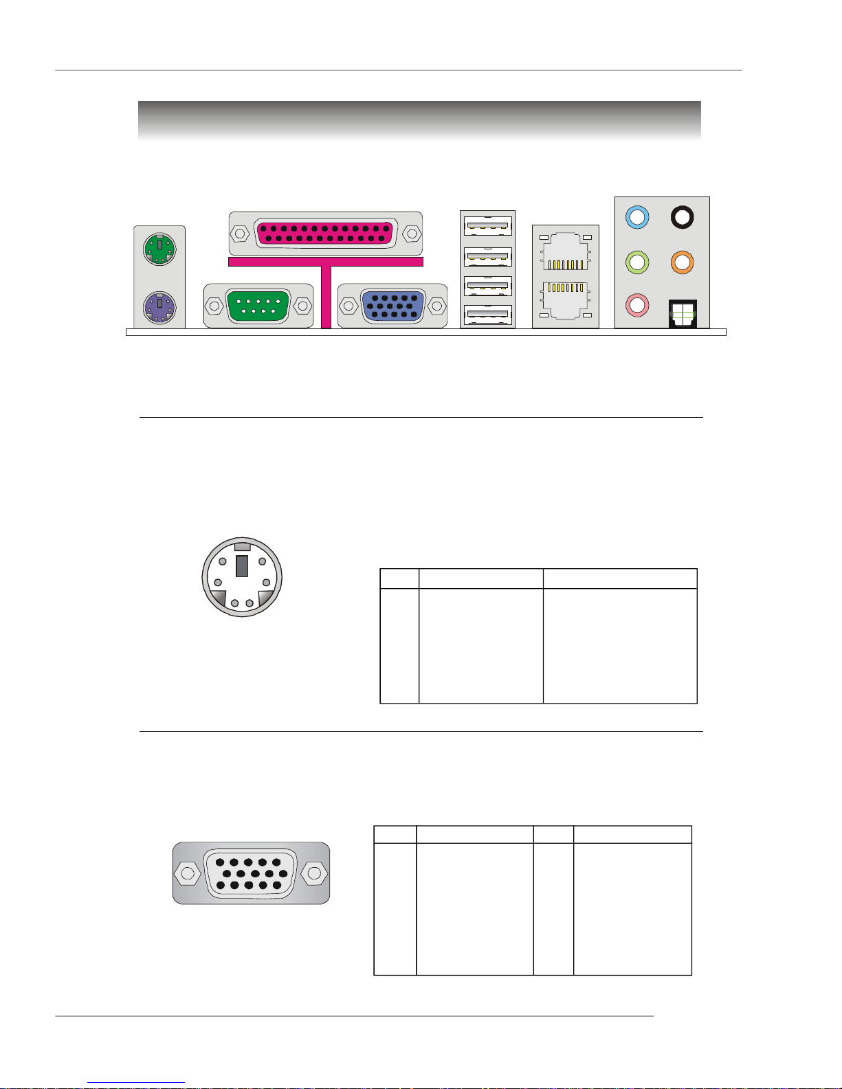
Back Panel
Hardware Setup
L-In
LAN
RS-Out
Keyboard
COM Port
VGA Port
USB Ports
L-Out
Mic
CS-Out
SPDIF Out
(Optical)
Mouse Connector (Green) / Keyboard Connector (Purple)
The mainboard provides a standard PS/2® mouse/keyboard mini DIN connector for
attaching a PS/2® mouse/keyboard. You can plug a PS/2® mouse/keyboard directly
into this connector. The connector location and pin assignments are as follows:
6
4
2
PS/2 Mouse / Keyboard
(6-pin Female)
5
3
1
PIN SIGNAL DESCRIPTION
1 Mouse/Keyboard Data Mouse/Keyboard data
2 NC No connection
3 GND Ground
4 VCC +5V
5 Mouse/Keyboard Clock Mouse/Keyboard clock
6 NC No connection
Pin Definition
VGA Port
The mainboard provides a DB 15-pin female connector to connect a VGA monitor.
5
15
VGA Connector
(DB 15-pin)
1
11
Pin Signal Description Pin Signal Description
1 RED 2 GREEN
3 BLUE 4 N/C
5 GND 6 GND
7 GND 8 GND
9 +5V 10 GND
11 N/C 12 SDA
13 Horizontal Sync 14 Vertical Sync
15 SCL
2-9
MS-9625 M-ATX Workstation Board
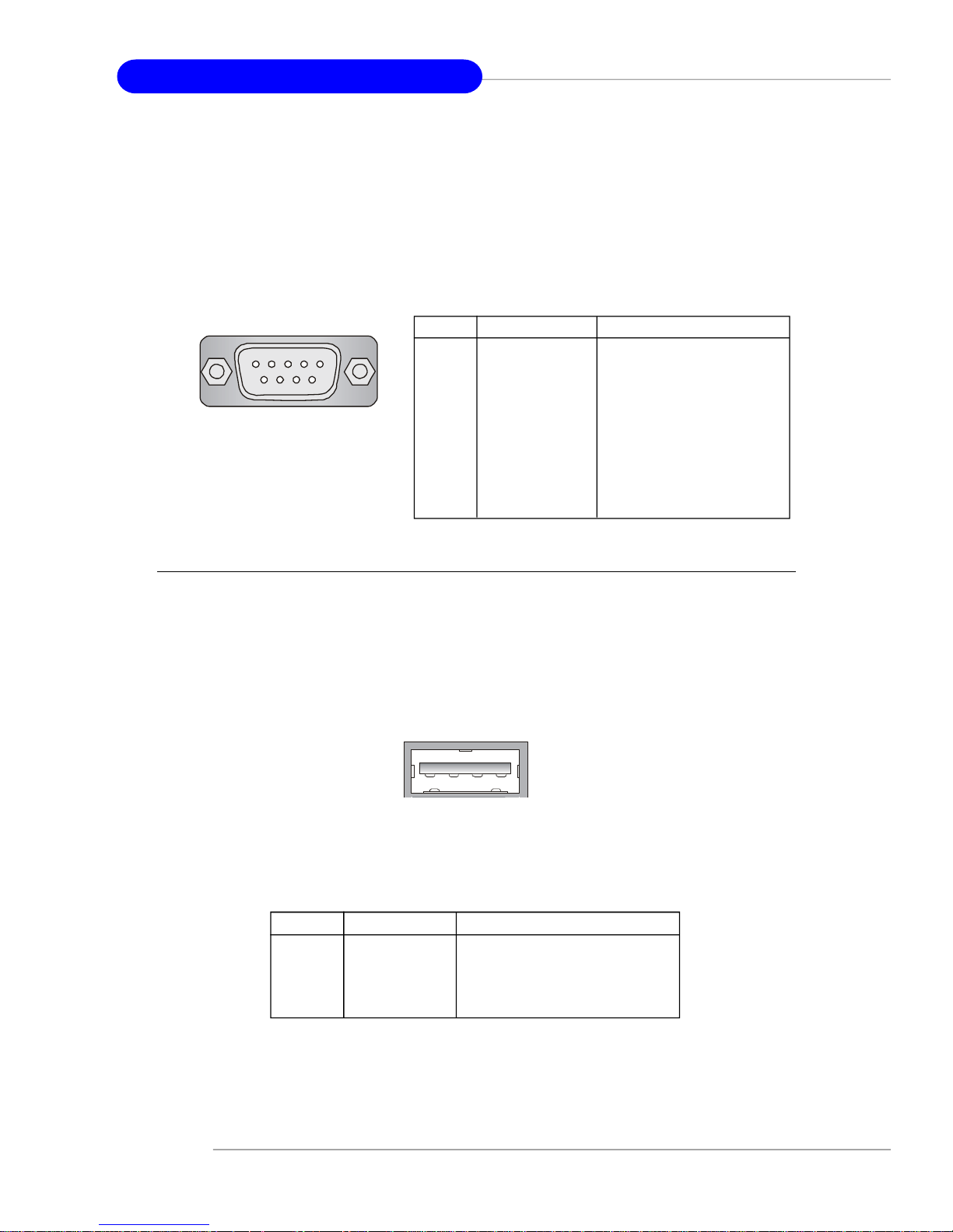
Serial Port
The mainboard offers one 9-pin male DIN connector as the serial port. The port is a
16550A high speed communication port that sends/receives 16 bytes FIFOs. You can
attach a serial mouse or other serial devices directly to the connector.
Pin Definition
1 2 3 4 5
6 7 8 9
9-Pin Male DIN Connector
PIN SIGNAL DESCRIPTION
1 DCD Data Carry Detect
2 SIN Serial In or Receive Data
3 SOUT Serial Out or Transmit Data
4 DTR Data Terminal Ready
5 GND Ground
6 DSR Data Set Ready
7 RTS Request To Send
8 CTS Clear To Send
9 RI Ring Indicate
USB Ports
The rear panel provides four UHCI (Universal Host Controller Interface) Universal
Serial Bus roots for attaching USB devices such as keyboard, mouse or other USBcompatible devices. You can plug the USB device directly into the connector.
1 2 3 4
USB Port
USB Port Description
PIN SIGNAL DESCRIPTION
1 VCC +5V
2 -Data 0 Negative Data Channel 0
3 +Data0 Positive Data Channel 0
4 GND Ground
2-10
Hardware Setup
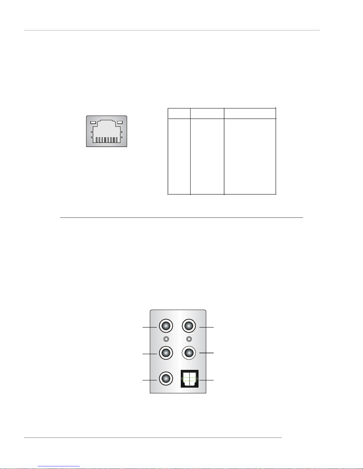
LAN (RJ-45) Jacks
The mainboard provides 2 standard RJ-45 jacks for connection to single Local Area
Network (LAN). This Giga-bit LAN enables data to be transferred at 1000, 100 or
10Mbps. You can connect a network cable to either LAN jack.
Giga-bit LAN Pin Definition
PIN SIGNAL DESCRIPTION
1 D0P Differential Pair 0+
2 D0N Differential Pair 03 D1P Differential Pair 1+
RJ-45 LAN Jack
4 D2P Differential Pair 2+
5 D2N Differential Pair 26 D1N Differential Pair 17 D3P Differential Pair 3+
8 D3N Differential Pair 3-
Audio Port Connectors
The left 3 audio jacks are 2-channel mode for stereo speaker output. Line Out is a
connector for Speakers or Headphones. Line In is used for external CD player, Tape
player, or other audio devices. Mic is a connector for microphones.
However, there is an advanced audio application provided by Realtek ALC880 to
offer support for 7.1-channel audio operation and can turn rear audio connectors
from 2-channel to 4-/5.1-/7.1 channel audio.
Line In
(in 7.1CH)
Line Out
MIC
Rear Speaker Out
(in 7.1CH / 6CH / 4CH)
Center/Subwoofer
Speaker Out
( in 7.1CH / 6CH)
S/PDIF Out-Optical
(in 7.1CH / 6CH)
2-11
MS-9625 M-ATX Workstation Board
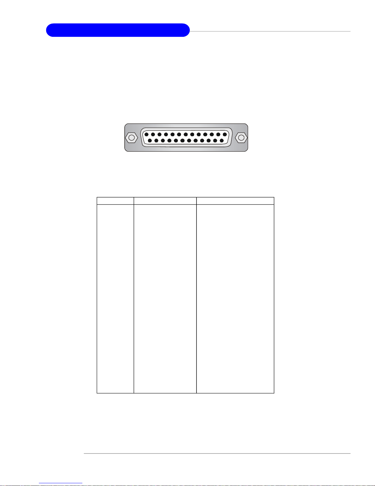
Parallel Port Connector: LPT1
The mainboard provides a 25-pin female centronic connector as LPT. A parallel port is
a standard printer port that supports Enhanced Parallel Port (EPP) and Extended
Capabilities Parallel Port (ECP) mode.
13 1
25
14
Pin Definition
PIN SIGNAL DESCRIPTION
1 STROBE Strobe
2 DATA0 Data0
3 DATA1 Data1
4 DATA2 Data2
5 DATA3 Data3
6 DATA4 Data4
7 DATA5 Data5
8 DATA6 Data6
9 DATA7 Data7
10 ACK# Acknowledge
11 BUSY Busy
12 PE Paper End
13 SELECT Select
14 AUTO FEED# Automatic Feed
15 ERR# Error
16 INIT# Initialize Printer
17 SLIN# Select In
18 GND Ground
19 GND Ground
20 GND Ground
21 GND Ground
22 GND Ground
23 GND Ground
24 GND Ground
25 GND Ground
2-12
Hardware Setup
Connectors
The mainboard provides connectors to connect to FDD, IDE HDD, case, LAN, USB
Ports, CPU/system power supply fans, ... and etc.
Floppy Disk Drive Connector: FDD1
The mainboard provides a standard floppy disk drive connector that supports 360K,
720K, 1.2M, 1.44M and 2.88M floppy disk types.
FDD1
Hard Disk Connector: IDE1
The mainboard provides a one-channel Ultra ATA 100 bus Master IDE controller that
supports PIO mode 0 ~ 4, Bus Master, and Ultra DMA 33/66/100 function. You can
connect up to two hard disk drives, CD-ROM drives, 120MB floppy disk drive (reserved
for future BIOS), and other devices.
IDE1
IDE1 Definition
IDE VDMA Controller RAID ATAPI
1 66/100 Intel ICH6 N/A Yes
IDE1 (Primary IDE Connector)
IDE1 can connect a Master and a Slave drive. You must configure the second
hard drive to Slave mode by setting the jumper accordingly.
MSI Reminds You...
If you install two hard disks on cable, you must configure the second
drive to Slave mode by setting its jumper. Refer to the hard disk documentation supplied by hard disk vendors for jumper setting instructions.
2-13
MS-9625 M-ATX Workstation Board
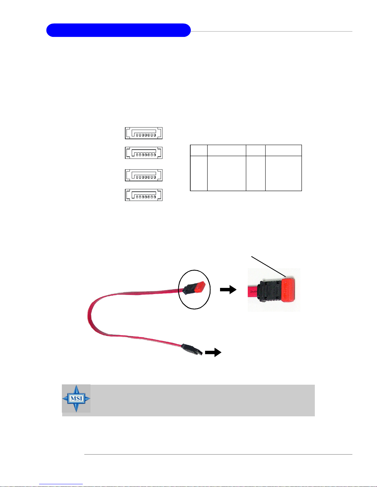
Serial ATA Connectors: SATA1, SATA2, SATA3, SATA4
This mainboard provides four high-speed Serial ATA interface ports. Each supports
1st generation serial ATA data rates of 150 MB/s and is fully compliant with Serial ATA
1.0 specifications. Each Serial ATA connector can connect to 1 hard disk device.
71
SATA4
SATA1/2/3/4 Pin Definition
SATA3
SATA2
SATA1
Optional Serial ATA cable
PIN SIGNAL PIN SIGNAL
1 GND 2 TXP
3 TXN 4 GND
5 RXN 6 RXP
7 GND
Take out the dust cover and connect
to the hard disk devices
MSI Reminds You...
Please do not fold the Serial ATA cable into 90-degree angle. Otherwise,
the loss of data may occur during transmission.
2-14
Connect to SATA1/2/3/4
 Loading...