

Page 1
Wind Board 330
MS-7314 (v2.X) Mainboard
G52-73141X8
i
Page 2

Copyright Notice
The material in this document is the intellectual property of MICRO-STAR
INTERNATIONAL. We take every care in the preparation of this document, but no
guarantee is given as to the correctness of its contents. Our products are under
continual improvement and we reserve the right to make changes without notice.
Trademarks
All trademarks are the properties of their respective owners.
NVIDIA, the NVIDIA logo, DualNet, and nForce are registered trademarks or trade-
marks of NVIDIA Corporation in the United States and/or other countries.
AMD, Athlon™, Athlon ™ XP, Thoroughbred™, and Duron™ are registered trademarks of AMD Corporation.
Intel® and Pentium® are registered trademarks of Intel Corporation.
PS/2 and OS®/2 are registered trademarks of International Business Machines
Corporation.
Windows® NT/XP are registered trademarks of Microsoft Corporation.
Netware® is a registered trademark of Novell, Inc.
Award® is a registered trademark of Phoenix Technologies Ltd.
AMI® is a registered trademark of American Megatrends Inc.
Revision History
Revision Revision History Date
V1.0 First release for Europe November 2008
Technical Support
If a problem arises with your system and no solution can be obtained from the user’s
manual, please contact your place of purchase or local distributor. Alternatively,
please try the following help resources for further guidance.
Visit the MSI website for FAQ, technical guide, BIOS updates, driver updates,
and other information: http://global.msi.com.tw/index.php?
func=service
Contact our technical staff at: http://ocss.msi.com.tw
ii
Page 3
Safety Instructions
1. Always read the safety instructions carefully.
2. Keep this User’s Manual for future reference.
3. Keep this equipment away from humidity.
4. Lay this equipment on a reliable flat surface before setting it up.
5. The openings on the enclosure are for air convection hence protects the equipment from overheating. DO NOT COVER THE OPENINGS.
6. Make sure the voltage of the power source and adjust properly 110/220V before connecting the equipment to the power inlet.
7. Place the power cord such a way that people can not step on it. Do not place
anything over the power cord.
8. Always Unplug the Power Cord before inserting any add-on card or module.
9. All cautions and warnings on the equipment should be noted.
10.Never pour any liquid into the opening that could damage or cause electrical
shock.
11. If any of the following situations arises, get the equipment checked by service
personnel:
† The power cord or plug is damaged.
† Liquid has penetrated into the equipment.
† The equipment has been exposed to moisture.
† The equipment does not work well or you can not get it work according to
User’s Manual.
† The equipment has dropped and damaged.
† The equipment has obvious sign of breakage.
12. DO NOT LEAVE THIS EQUIPMENT IN AN ENVIRONMENT UNCONDITIONED, STORAGE TEMPERATURE ABOVE 600 C (1400F), IT MAY DAMAGE THE EQUIPMENT.
CAUTION: Danger of explosion if battery is incorrectly replaced.
Replace only with the same or equivalent type recommended by the
manufacturer.
iii
Page 4

FCC-B Radio Frequency Interference Statement
This equipment has been
tested and found to comply
with the limits for a Class B
digital device, pursuant to Part
15 of the FCC Rules. These limits are designed to provide reasonable protection
against harmful interference in a residential installation. This equipment generates,
uses and can radiate radio frequency energy and, if not installed and used in accordance with the instructions, may cause harmful interference to radio communications.
However, there is no guarantee that interference will not occur in a particular
installation. If this equipment does cause harmful interference to radio or television
reception, which can be determined by turning the equipment off and on, the user is
encouraged to try to correct the interference by one or more of the measures listed
below.
† Reorient or relocate the receiving antenna.
† Increase the separation between the equipment and receiver.
† Connect the equipment into an outlet on a circuit different from that to
which the receiver is connected.
† Consult the dealer or an experienced radio/television technician for help.
Notice 1
The changes or modifications not expressly approved by the party responsible for
compliance could void the user’s authority to operate the equipment.
Notice 2
Shielded interface cables and A.C. power cord, if any, must be used in order to
comply with the emission limits.
VOIR LA NOTICE D’ INSTALLATION AVANT DE RACCORDER AU RESEAU.
Micro-Star International
MS-7314
This device complies with Part 15 of the FCC Rules. Operation is subject to the
following two conditions:
(1) this device may not cause harmful interference, and
(2) this device must accept any interference received, including interference that
may cause undesired operation.
iv
Page 5
WEEE (Waste Electrical and Electronic Equipment) Statement
v
Page 6
vi
Page 7
vii
Page 8

CONTENTS
Copyright Notice................................................................................................ii
Trademarks........................................................................................................ii
Revision History................................................................................................ii
Technical Support.............................................................................................ii
Safety Instructions..........................................................................................iii
FCC-B Radio Frequency Interference Statement.........................................iv
WEEE (Waste Electrical and Electronic Equipment) Statement.....................v
English...........................................................................................................En-1
Mainboard Specifications...........................................................................En-2
Quick Components Guide...........................................................................En-4
Memory.....................................................................................................En-5
Power Supply............................................................................................En-7
Back Panel.................................................................................................En-8
Connectors..............................................................................................En-10
Jumper....................................................................................................En-15
Slot..........................................................................................................En-16
BIOS Setup..............................................................................................En-17
Software Information...............................................................................En-23
Deutsch.........................................................................................................De-1
Spezifikationen.........................................................................................De-2
Komponenten-Übersicht...........................................................................De-4
Speicher...................................................................................................De-5
Stromversorgung......................................................................................De-7
Rücktafel..................................................................................................De-8
Anschlüsse............................................................................................De-10
Steckbrücke............................................................................................De-15
Steckplätze.............................................................................................De-16
BIOS Setup.............................................................................................De-17
Software-Information..............................................................................De-23
viii
Page 9

Français..........................................................................................................Fr-1
Spécifications............................................................................................Fr-2
Guide rapide des composants...................................................................Fr-4
Mémoire.....................................................................................................Fr-5
Connecteurs d’ alimentation........................................................................Fr-7
Panneau arrière.........................................................................................Fr-8
Connecteurs.............................................................................................Fr-10
Cavalier....................................................................................................Fr-15
Slot...........................................................................................................Fr-16
Réglages BIOS..........................................................................................Fr-17
Information de Logiciel..............................................................................Fr-23
Русский .........................................................................................................Ru-1
Характеристики ......................................................................................Ru-2
Руководство по размещению компонентов .........................................Ru-4
Память ....................................................................................................Ru-5
Разъем питания ......................................................................................Ru-7
Задняя панель ........................................................................................Ru-8
Коннекторы............................................................................................Ru-10
Перемычки .............................................................................................Ru-15
Слоты .....................................................................................................Ru-16
Настройка BIOS......................................................................................Ru-17
Сведения о программном обеспечении...............................................Ru-23
ix
Page 10

Wind Board 330
User’s Guide
English
English
En-1
Page 11
MS-7314 Mainboard
Mainboard Specifications
Processor Support
- Intel® ATom CPU 330
Supported FSB
- 533 MHz
Chipset
- North Bridge: Intel® 945GC chipset
- South Bridge: Intel® ICH7 chipset
Memory Support
- DDR2 533 SDRAM (2GB Max)
- 1 DDR2 DIMM (240pin / 1.8V), single channel
(For more information on compatible components, please visit
http://global.msi.com.tw/index.php?func=testreport)
LAN
- Supports Realtek® RTL8101E 10/100 Mb/s
- Supports ACPI Power Management
Audio
- Chip integrated by Realtek® ALC888, supports 5.1-channel audioout
- Supports Windows® VistaTM premium compliance
IDE
- 1 IDE port by Intel® ICH7
- Supports Ultra DMA 66/100 mode
- Supports PIO, Bus Master operation mode
SATA
- 2 SATAII ports by Intel® ICH7
- Supports 2 SATAII devices
- Supports storage and data transfers at up to 3 Gb/s
En-2
Page 12
Connectors
Back panel
- 1 PS/2 mouse port
- 1 PS/2 keyboard port
- 1 serial port (COM1)
- 1 VGA port
- 1 parallel port supporting SPP/EPP/ECP mode
- 4 USB 2.0 Ports
- 1 RJ-45 LAN jack
- 3 flexible audio jacks
On-Board Pinheaders / Connectors
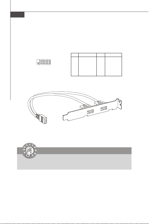
- 2 USB 2.0 pinheaders
- 1 Front Panel Audio pinheader
- 1 Chassis intrusion pinheader
- 1 Speaker pinheader
Slots
- 1 PCI slot, supports 3.3V/ 5V PCI bus Interface
Form Factor
- Mini-ITX (17.0cm X 17.0cm)
Mounting
- 4 mounting holes
English
En-3
Page 13
MS-7314 Mainboard
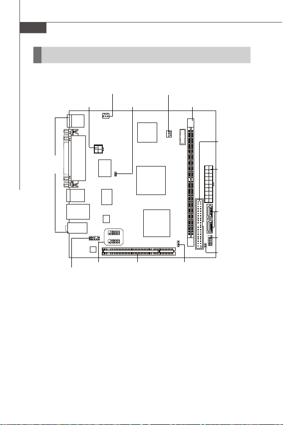
Quick Components Guide
SYS_FAN1, En-12 SYS_FAN2, En-12
JPW1, En-7
Back Panel,
En-8
JUSB1~2,
JAUD1,
En-14
En-12
JCI1, En-13
PCI,
En-16
DDR2 DIMMs, En-5
JBAT1,
En-15
IDE1, En-10
ATX1, En-7
SATA, En-11
JFP1, En-13
JBR1, En-11
En-4
Page 14
Memory
The DIMM slot is used for installing memory module.
For more information on compatible components, please visit http://global.msi.com.
tw/index.php?func=testreport
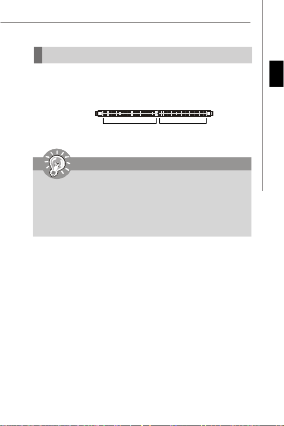
DDR2
240-pin, 1.8V
Important
-DDR2 memory module is not interchangeable with DDR and the DDR2 standard is not backwards compatible. You should always install DDR2 memory
module in the DDR2 DIMM slot.
- For more information on compatible components, please visit http://global.
msi.com.tw/index.php?func=testreport
- Due to the CPU limitation, the installed 667 MHz memory will be dropped to
533 MHz for system stability.
64x2=128 pin 56x2=112 pin
English
En-5
Page 15
MS-7314 Mainboard
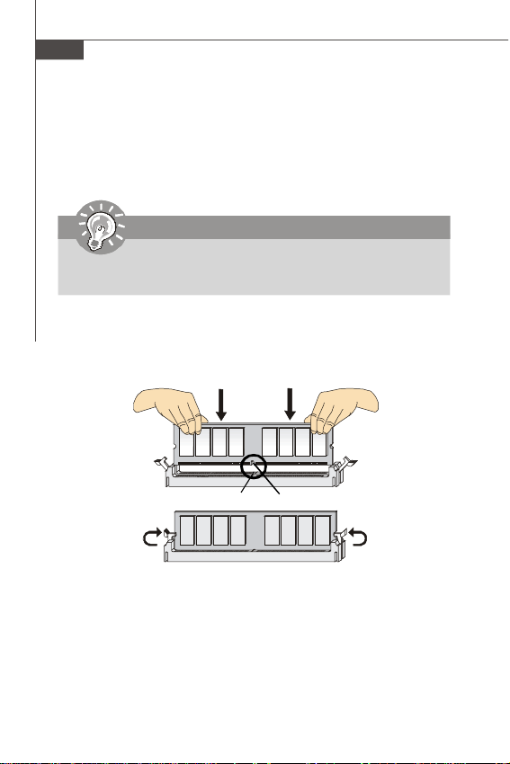
Installing Memory Modules
1. The memory module has only one notch on the center and will only fit in the right
orientation.
2. Insert the memory module vertically into the DIMM slot. Then push it in until the
golden finger on the memory module is deeply inserted in the DIMM slot. The plastic
clip at each side of the DIMM slot will automatically close when the memory module
is properly seated.
Important
You can barely see the golden finger if the memory module is properly inserted
in the DIMM slot.
3. Manually check if the memory module has been locked in place by the DIMM slot
clips at the sides.
En-6
Volt
Notch
Page 16
Power Supply
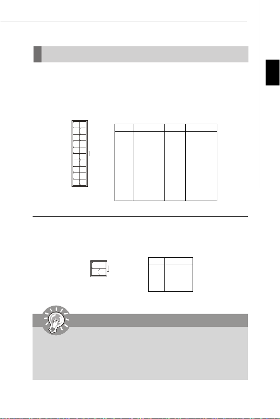
ATX 20-Pin Power Connector: ATX1
This connector allows you to connect to an ATX power supply. To connect to the ATX
power supply, make sure the plug of the power supply is inserted in the proper
orientation and the pins are aligned. Then push down the power supply firmly into the
connector.
10120
11
ATX1
ATX 4-pin Power Connector: JPW1
This power connector is used to provide power to the CPU.
1 3
JPW1
42
Pin Definition
PIN SIGNAL
1 3.3V
2 3.3V
3 GND
4 5V
5 GND
6 5V
7 GND
8 PW_OK
9 5V_SB
10 12V
PIN SIGNAL
11 3.3V
12 -12V
13 GND
14 PS_ON
15 GND
16 GND
17 GND
18 -5V
19 5V
20 5V
Pin Definition
PIN SIGNAL
1 GND
2 GND
3 12V
4 12V
Important
1. For more information on compatible components, please visit http://global.
msi.com.tw/index.php?func=testreport
2. Make sure that all the connectors are connected to proper ATX power
supplies to ensure stable operation of the mainboard.
3. Power supply of 400 watts (and lower) is strongly recommended for system
stability.
English
En-7
Page 17
MS-7314 Mainboard
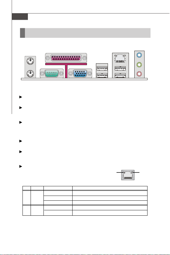
Back Panel
Mouse
Keyboard
Mouse/Keyboard
The standard PS/2® mouse/keyboard DIN connector is for a PS/2® mouse/keyboard.
Parallel Port
A parallel port is a standard printer port that supports Enhanced Parallel Port (EPP)
and Extended Capabilities Parallel Port (ECP) mode.
Serial Port
The serial port is a 16550A high speed communications port that sends/ receives 16
bytes FIFOs. You can attach a serial mouse or other serial devices directly to the
connector.
VGA Port
The DB15-pin female connector is provided for monitor.
USB Port
The USB (Universal Serial Bus) port is for attaching USB devices such as keyboard,
mouse, or other USB-compatible devices.
LAN
The standard RJ-45 LAN jack is for connection to the
Local Area Network (LAN). You can connect a network
cable to it.
LED Color LED State Condition
Left Yellow On (steady state) LAN link is established.
Green Off 10 Mbit/sec data rate is selected.
Right
Parallel Port
Serial Port USB Port
Off LAN link is not established.
On (brighter & pulsing)The computer is communicating with another computer on the LAN.
On 100 Mbit/sec data rate is selected.
VGA Port
LAN
USB Port
Line-In
Line-Out
Mic
GreenYellow
En-8
Page 18

Audio Ports
These audio connectors are used for audio devices. It is easy to differentiate between audio effects according to the color of audio jacks.
Line-In (Blue) - Line In is used for external CD player, tapeplayer or
Line-Out (Green) - Line Out, is a connector for speakers or headphones.
Mic (Pink) - Mic, is a connector for microphones.
other audio devices.
Important
The Realtek audio provided to offer support for 5.1-channel audio operation
and can turn rear audio connectors from 2-channel to 4-/ 5.1-channel audio.
English
En-9
Page 19
MS-7314 Mainboard
Connectors
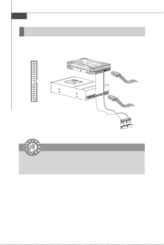
IDE Connector: IDE1
This connector supports IDE hard disk drives, optical disk drives and other IDE devices.
IDE1
Important
If you install two IDE devices on the same cable, you must configure the
drives separately to master / slave mode by setting jumpers. Refer to IDE
device’s documentation supplied by the vendors for jumper setting
instructions.
En-10
Page 20
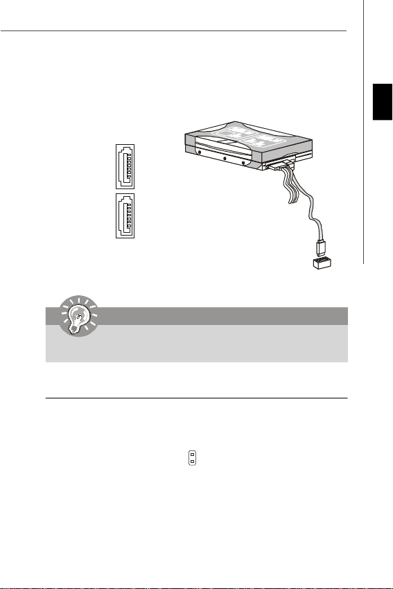
Serial ATA Connector: SATA1~2
This connector is a high-speed Serial ATA interface port. Each connector can connect to one Serial ATA device.
SATA1
SATA2
Important
Please do not fold the Serial ATA cable into 90-degree angle. Otherwise,
data loss may occur during transmission.
Speaker Connector: JBR1
This connector connects to the speaker of the case.
2
SPK-
1
SPK+
JBR1
English
En-11
Page 21
MS-7314 Mainboard
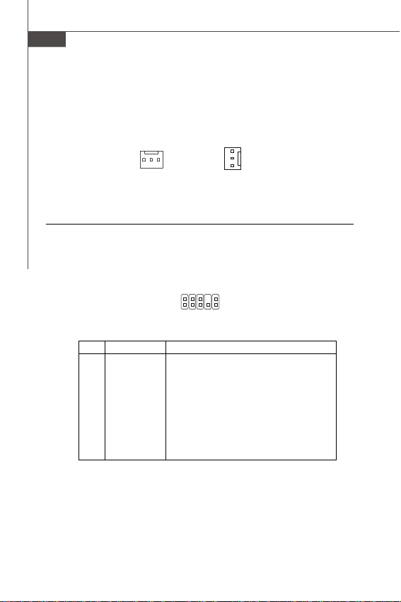
Fan Power Connectors: SYS_FAN1/ SYS_FAN2
The fan power connectors support system cooling fan with +12V. When connecting
the wire to the connectors, always note that the red wire is the positive and should
be connected to the +12V; the black wire is Ground and should be connected to GND.
SEN SOR
+1 2V
GND
SENSOR
+12V
GND
SYS_FAN2SYS_FAN1
Front Panel Audio Connector: JAUD1
This connector allows you to connect the front panel audio and is compliant with
Intel® Front Panel I/O Connectivity Design Guide.
JAUD1
2
1
Pin Definition
PIN SIGNAL DESCRIPTION
1 MIC_L Microphone - Left channel
2 GND Ground
3 MIC_R Microphone - Right channel
4 NC
5 LINE out_R Analog Port - Right channel
6 MIC_JD Jack detection return from front panel microphone JACK1
7 Front_JD Jack detection sense line from the High Definition Audio CODEC
8 NC No control
9 LINE out_L Analog Port - Left channel
10 LINEout_JD Jack detection return from front panel JACK2
jack detection resistor network
10
9
En-12
Page 22
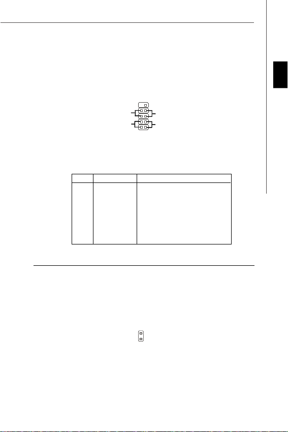
Front Panel Connector: JFP1
This connector is for electrical connection to the front panel switches and LEDs. The
JFP1 is compliant with Intel® Front Panel I/O Connectivity Design Guide.
910
-
Power
Switch++
Power
LED
2
JFP1
+
Reset
-
Switch
-
HDD
LED
1
JFP1 Pin Definition
PIN SIGNAL DESCRIPTION
1 HD_LED + Hard disk LED pull-up
2 FP PWR/SLP MSG LED pull-up
3 HD_LED - Hard disk active LED
4 FP PWR/SLP MSG LED pull-up
5 RST_SW - Reset Switch low reference pull-down to GND
6 PWR_SW + Power Switch high reference pull-up
7 RST_SW + Reset Switch high reference pull-up
8 PWR_SW - Power Switch low reference pull-down to GND
9 RSVD_DNU Reserved. Do not use.
Chassis Intrusion Connector: JCI1
This connector connects to the chassis intrusion switch cable. If the chassis is
opened, the chassis intrusion mechanism will be activated. The system will record
this status and show a warning message on the screen. To clear the warning, you
must enter the BIOS utility and clear the record.
1
CINTRU
2
GND
JCI1
English
En-13
Page 23
MS-7314 Mainboard
Front USB Connector: JUSB1~2
These connectors, compliant with Intel® I/O Connectivity Design Guide, is ideal for
connecting high-speed USB interface peripherals such as USB HDD, digital cameras,
MP3 players, printers, modems and the like.
Pin Definition
PIN SIGNAL PIN SIGNAL
9
10
JUSB1/2
1
2
1 VCC 2 VCC
3 USB0- 4 USB15 USB0+ 6 USB1+
7 GND 8 GND
9 Key (no pin) 10 NC
USB 2.0 Bracket
(optional)
Important
Note that the pins of VCC and GND must be connected correctly to avoid
possible damage.
En-14
Page 24
Jumper
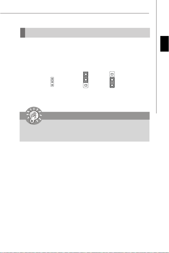
Clear CMOS Jumper: JBAT1
There is a CMOS RAM onboard that has a power supply from an external battery to
keep the data of system configuration. With the CMOS RAM, the system can automatically boot OS every time it is turned on. If you want to clear the system configuration,
set the jumper to clear data.
JBAT1
1
1
3
Keep Data Clear Data
1
3
Important
You can clear CMOS by shorting 2-3 pin while the system is off. Then return
to 1-2 pin position. Avoid clearing the CMOS while the system is on; it will
damage the mainboard.
English
En-15
Page 25
MS-7314 Mainboard
Slot
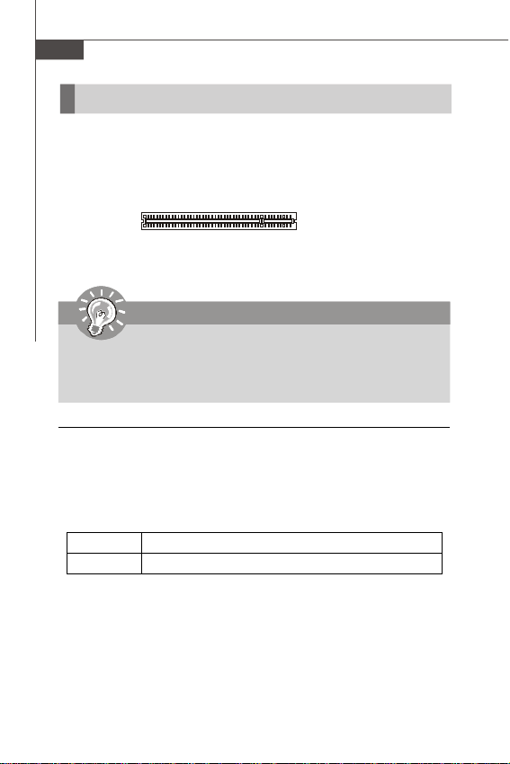
PCI (Peripheral Component Interconnect) Slot
The PCI slot supports LAN card, SCSI card, USB card, and other add-on cards that
comply with PCI specifications.
32-bit PCI Slot
Important
When adding or removing expansion cards, make sure that you unplug the
power supply first. Meanwhile, read the documentation for the expansion card
to configure any necessary hardware or software settings for the expansion
card, such as jumpers, switches or BIOS configuration.
PCI Interrupt Request Routing
The IRQ, acronym of interrupt request line and pronounced I-R-Q, are hardware lines
over which devices can send interrupt signals to the microprocessor. The PCI IRQ
pins are typically connected to the PCI bus pins as follows:
Order 1 Order 2 Order 3 Order 4
PCI Slot 1 INT A# INT B# INT C# INT D#
En-16
Page 26
BIOS Setup
This chapter provides basic information on the BIOS Setup program and allows you
to configure the system for optimum use. You may need to run the Setup program
when:
* An error message appears on the screen during the system booting up, and requests
you to run BIOS SETUP.
* You want to change the default settings for customized features.
Important
1.The items under each BIOS category described in this chapter are under
continuous update for better system performance. Therefore, the description
may be slightly different from the latest BIOS and should be held for reference
only.
2.Upon boot-up, the 1st line appearing after the memory count is the BIOS
version. It is usually in the format:
A7314IMS V4.0 110208 where:
1st digit refers to BIOS maker as A = AMI, W = AWARD, and P = PHOENIX.
2nd - 5th digit refers to the model number.
6th refers to the Chipset vender as A = AMD, I = Intel, V = VIA, N = Nvidia, U =
ULi.
7th - 8th digit refers to the customer as MS = all standard customers.
V4.0 refers to the BIOS version.
110208 refers to the date this BIOS was released.
English
En-17
Page 27

MS-7314 Mainboard
Entering Setup
Power on the computer and the system will start POST (Power On Self Test) process.
When the message below appears on the screen, press <DEL> key to enter Setup.
Press DEL to enter SETUP
If the message disappears before you respond and you still wish to enter Setup,
restart the system by turning it OFF and On or pressing the RESET button. You may
also restart the system by simultaneously pressing <Ctrl>, <Alt>, and <Delete> keys.
Getting Help
After entering the Setup menu, the first menu you will see is the Main Menu.
Main Menu
The main menu lists the setup functions you can make changes to. You can use the
arrow keys (↑↓ ) to select the item. The on-line description of the highlighted setup
function is displayed at the bottom of the screen.
Sub-Menu
If you find a right pointer symbol (as shown in the right view)
appears to the left of certain fields that means a sub-menu
containing additional options can be launched from this field.
You can use control keys (↑↓ ) to highlight the field and press <Enter> to call up the
sub-menu. Then you can use the control keys to enter values and move from field to
field within a sub-menu. If you want to return to the main menu, just press <Esc >.
General Help <F1>
The BIOS setup program provides a General Help screen. You can call up this screen
from any menu by simply pressing <F1>. The Help screen lists the appropriate keys
to use and the possible selections for the highlighted item. Press <Esc> to exit the
Help screen.
En-18
Page 28
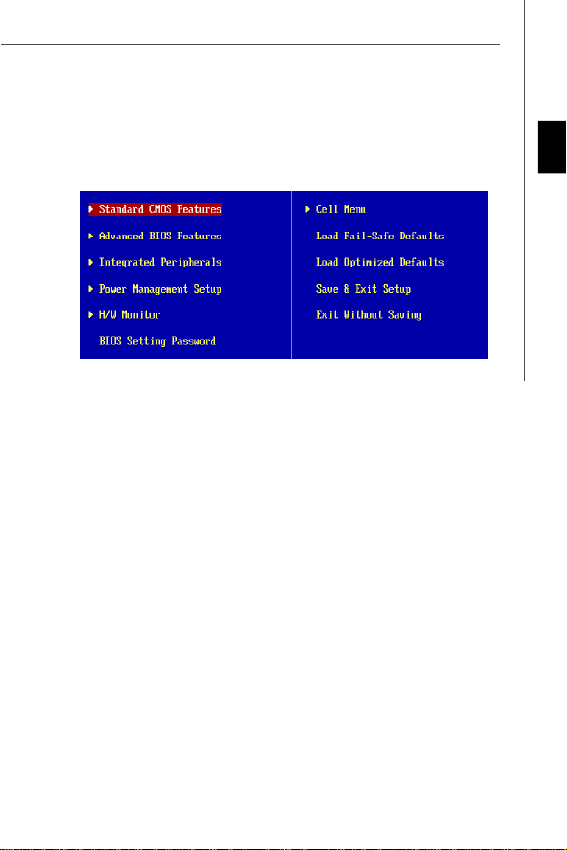
The Main Menu
Once you enter AMI® or AWARD® BIOS CMOS Setup Utility, the Main Menu will appear
on the screen. The Main Menu allows you to select from the setup functions and two
exit choices. Use arrow keys to select among the items and press <Enter> to accept
or enter the sub-menu.
Standard CMOS Features
Use this menu for basic system configurations, such as time, date etc.
Advanced BIOS Features
Use this menu to setup the items of special enhanced features.
Integrated Peripherals
Use this menu to specify your settings for integrated peripherals.
Power Management Setup
Use this menu to specify your settings for power management.
H/W Monitor
This entry shows your PC health status.
BIOS Setting Password
Use this menu to set the Password.
Cell Menu
Use this menu to specify your settings for frequency/voltage control and overclocking.
Load Fail-Safe Defaults
Use this menu to load the default values set by the BIOS vendor for stable system
performance.
Load Optimized Defaults
Use this menu to load the default values set by the mainboard manufacturer specifically
for optimal performance of the mainboard.
Save & Exit Setup
Save changes to CMOS and exit setup.
Exit Without Saving
Abandon all changes and exit setup.
English
En-19
Page 29
MS-7314 Mainboard
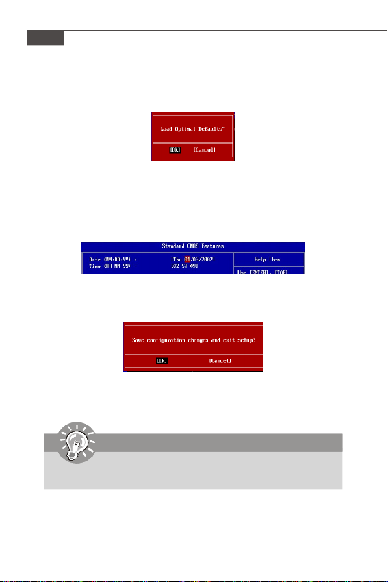
When enter the BIOS Setup utility, follow the processes below for general use.
1. Load Optimized Defaults : Use control keys (↑↓) to highlight the Load
Optimized Defaults field and press <Enter> , a message as below appears:
Select [Ok] and press Enter to load the default settings for optimal system
performance.
2. Setup Date/ Time : Select the Standard CMOS Features and press <Enter> to
enter the Standard CMOS Features-menu. Adjust the Date, Time fields.
3. Save & Exit Setup : Use control keys (↑↓) to highlight the Save & Exit Setup
field and press <Enter> , a message as below appears:
Select [Ok] and press Enter to save the configurations and exit BIOS Setup utility.
Important
The configuration above are for general use only. If you need the detailed
settings of BIOS, please read the manual in English version on MSI website.
En-20
Page 30
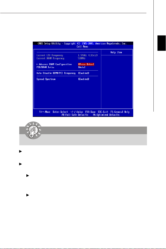
4. Cell Menu Introduction : This menu is for advanced user who want to overclock
the mainboard.
Important
Change these settings only if you are familiar with the chipset.
Current CPU / DRAM Frequency
These items show the current clocks of CPU and Memory speed. Read-only.
Advance DRAM Configuration
Press <Enter> to enter the sub-menu.
Configure DRAM Timing by SPD
Setting to [Auto] enables DRAM timings and the following related items automatically
to be determined by BIOS based on the configurations on the SPD (Serial Presence
Detect) EEPROM on the DRAM module.
CAS# Latency (CL)
When the Configure DRAM Timing by SPD sets to [Manual], the field is
adjustable. This controls the CAS latency, which determines the timing delay (in
clock cycles) before SDRAM starts a read command after receiving it.
English
En-21
Page 31

MS-7314 Mainboard
tRCD
When the Configure DRAM Timing by SPD sets to [Manual], the field is
adjustable. When DRAM is refreshed, both rows and columns are addressed
separately. This setup item allows you to determine the timing of the transition
from RAS (row address strobe) to CAS (column address strobe). The less the
clock cycles, the faster the DRAM performance.
tRP
When the Configure DRAM Timing by SPD sets to [Manual], this field is
adjustable. This setting controls the number of cycles for Row Address Strobe
(RAS) to be allowed to precharge. If insufficient time is allowed for the RAS to
accumulate its charge before DRAM refresh, refresh may be incomplete and
DRAM may fail to retain data. This item applies only when synchronous DRAM is
installed in the system.
tRAS
When the Configure DRAM Timing by SPD sets to [Manual], this field is
adjustable. This setting determines the time RAS takes to read from and write to
memory cell.
FSB/DRAM Ratio
This item will allow you to adjust the ratio of FSB to memory.
Auto Disable DRAM/PCI Frequency
When set to [Enabled], the system will remove (turn off) clocks from empty DIMM and
PCI slots to minimize the electromagnetic interference (EMI).
Spread Spectrum
When the mainboard’s clock generator pulses, the extreme values (spikes) of the
pulses create EMI (Electromagnetic Interference). The Spread Spectrum function
reduces the EMI generated by modulating the pulses so that the spikes of the pulses
are reduced to flatter curves. If you do not have any EMI problem, leave the setting at
Disabled for optimal system stability and performance. But if you are plagued by EMI,
set to Enabled for EMI reduction. Remember to disable Spread Spectrum if you are
overclocking because even a slight jitter can introduce a temporary boost in clock
speed which may just cause your overclocked processor to lock up.
Important
1.If you do not have any EMI problem, leave the setting at [Disabled] for
optimal system stability and performance. But if you are plagued by EMI,
select the value of Spread Spectrum for EMI reduction.
2.The greater the Spread Spectrum value is, the greater the EMI is reduced,
and the system will become less stable. For the most suitable Spread
Spectrum value, please consult your local EMI regulation.
3.Remember to disable Spread Spectrum if you are overclocking because
even a slight jitter can introduce a temporary boost in clock speed which
may just cause your overclocked processor to lock up.
En-22
Page 32

Software Information
Take out the Driver/Utility CD that is included in the mainboard package, and place it
into the CD-ROM drive. The installation will auto-run, simply click the driver or utility
and follow the pop-up screen to complete the installation. The Driver/Utility CD contains the:
Driver menu - The Driver menu shows the available drivers. Install the driver by your
desire and to activate the device.
Utility menu - The Utility menu shows the software applications that the mainboard
supports.
WebSite menu- The WebSite menu shows the necessary websites.
Important
Please visit the MSI website to get the latest drivers and BIOS for better system
performance.
English
En-23
Page 33

Wind Board 330
Benutzerhandbuch
Deutsch
Deutsch
De-1
Page 34

MS-7314 Mainboard
Spezifikationen
Prozessoren
- Intel® ATom CPU 330
FSB (Front-Side-Bus)
- 533 MHz
Chipsatz
- North-Bridge: Intel® 945GC Chipsatz
- South-Bridge: Intel® ICH7 Chipsatz
Speicher
- DDR2 533 SDRAM (max. 2GB)
- 1 DDR2 DIMM (240 Pin / 1.8V), Einkanal
(Weitere Informationen zu kompatiblen Speichermodulen finden
Sie unter http://global.msi.com.tw/index.php?func=testreport)
LAN
- Unterstützt Realtek® RTL8101E 10/100 Mb/s
- Unterstützt die Stromsparfunktionalität mit ACPI
Audio
- Onboard Soundchip über Realtek® ALC888, unterstützt 5.1-Kanal
Audio-Ausgang
- Zertifiziert fü r das Windows® VistaTM Premium Betriebs-system
IDE
- 1 IDE Port ü ber Intel® ICH7
- Unterstützt die Betriebmodi mit Ultra DMA 66/100
- Unterstützt die Betriebmodi mit PIO, Bus Mastering
SATA
- 2 SATAII Ports über Intel® ICH7
- Unterstützt 2 SATAII Geräte
- Unterstützt die Datenübertragungsraten von bis zu 3 Gb/s
De-2
Page 35

Anschlüsse
Hintere Ein-/ und Ausgänge
- 1 PS/2 Mausanschluss
- 1 PS/2 Tastaturanschluss
- 1 Serielle Anschluss (COM1)
- 1 VGA Anschluss
- 1 Parallele Schnittstelle, unterstützt die Modi SPP/EPP/ECP
- 4 USB 2.0 Anschlüsse
- 1 RJ-45 LAN Anschluss
- 3 Audiobuchsen
On-Board Stiftleiste/ Anschlüsse
- 2 USB 2.0 Stiftleisten
- 1 Audio Stiftleiste für Gehäuse Audio Ein-/ Ausgänge
- 1 Gehäusekontaktschalter
- 1 Lautsprecher Stiftleiste
Steckplätze
- 1 PCI Steckplatz
- Unterstützen 3.3V/ 5V PCI Bus Interface
Form Faktor
- Mini-ITX (17.0cm X 17.0cm)
Montage
- 4 Montagebohrungen
Deutsch
De-3
Page 36

MS-7314 Mainboard
Komponenten-Übersicht
SYS_FAN1, De-12 SYS_FAN2, De-12
JPW1, De-7
Back Panel,
De-8
JUSB1~2,
JAUD1,
De-14
De-12
JCI1, De-13
PCI,
De-16
DDR2 DIMMs, De-5
JBAT1,
De-15
IDE1, De-10
ATX1, De-7
SATA, De-11
JFP1, De-13
JBR1, De-11
De-4
Page 37

Speicher
Diese DIMM-Steckplätze nehmen Arbeitsspeichermodule auf.
Die neusten Informationen über kompatible Bauteile finden Sie unter http://global.msi.
com.tw/index.php?func=testreport
DDR2
240-polig, 1.8V
64x2=128 Pole 56x2=112 Pole
Wichtig
-DDR2 und DDR können nicht untereinander getauscht werden und der Stan-
dard DDR2 ist nicht abwärtskompatibel. Installieren Sie DDR2 Speichermodule stets in DDR2 DIMM Slots.
- Weitere Informationen über kompatible Bauteile finden Sie unter http://global.
msi.com.tw/index.php?func=testreport
- Wegen der CPU Beschrankung wird der eingebaute 667 MHz Speicher zu
533 MHz für dieSystemstabilitat abgesenkt.
De-5
Deutsch
Page 38

MS-7314 Mainboard
Installieren der Arbeitsspeichermodule
1. Das Arbeitsspeichermodul hat nur eine Kerbe in der Mitte und passt nur in eine
Richtung in den Steckplatz.
2. Stecken Sie das Arbeitsspeichermodul senkrecht in den DIMM-Steckplatz ein.
Drücken Sie anschlie ß end das Arbeitsspeichermodul nach unten, bis die
Kontaktseite richtig tief in dem DIMM-Steckplatz sitzt. Der Kunststoffbügel an jedem
Ende des DIMM-Steckplatzes schnappt automatisch ein, wenn das
Arbeitsspeichermodul richtig eingesetzt ist.
Wichtig
Die goldenen Kontakte sind kaum zu sehen, wenn das Arbeitsspeichermodul
richtig im DIMM-Steckplatz sitzt.
3. Prüfen Sie von Hand, ob das Arbeitsspeichermodul von den seitlichen Bügeln am
DIMM-Steckplatz richtig gehalten wird.
De-6
Volt
Kerbe
Page 39

Stromversorgung
ATX 20-poliger Stromanschluss: ATX1
Mit diesem Anschluss verbinden Sie den ATX Anschluss des Netzteils. Achten Sie bei
dem Verbinden des ATX Stromanschlusses darauf, dass der Anschluss des Netzteils
richtig auf den Anschluss an der Hauptplatine ausgerichtet ist. Drücken Sie dann den
Anschluss des Netzteils fest nach unten, um eine richtige Verbindung zu
gewährleisten.
10120
11
ATX1
ATX 4-poliger Stromanschluss: JPW1
Dieser Stromanschluss wird verwendet, um die CPU mit Strom zu versorgen.
Polzuweisung
PIN SIGNAL
1 3.3V
2 3.3V
3 GND
4 5V
5 GND
6 5V
7 GND
8 PW_OK
9 5V_SB
10 12V
PIN SIGNAL
11 3.3V
12 -12V
13 GND
14 PS_ON
15 GND
16 GND
17 GND
18 -5V
19 5V
20 5V
Deutsch
1 3
JPW1
42
Polzuweisung
PIN SIGNAL
1 GND
2 GND
3 12V
4 12V
Wichtig
1. Weitere Informationen ü ber kompatible Bauteile finden Sie unter http://
global.msi.com.tw/index.php?func=testreport
2. Stellen Sie sicher, dass diese Anschlü sse mit den richtigen Anschlüssen
des Netzteils verbunden werden, um einen stabilen Betrieb der Hauptplatine
sicherzustellen.
3. Für die Systemstabilität ist ein Netzteil mit 400 Watt (oder noch mehr)
empfehlenswert
De-7
Page 40

MS-7314 Mainboard
Rücktafel
Maus
Tastatur
Maus/Tastatur
Die Standard PS/2® Maus/Tastatur Stecker Mini DIN ist für eine PS/2® Maus/Tastatur.
Parallele Schnittstelle
Serielle
Schnittstelle
VGA Port
USB Port
LAN
USB Port
Line-In
Line-Out
Mik
Parallele Schnittstelle
Die Parallele Schnittstelle ist eine Standard Druckerschnittstelle, die ebenso als Enhanced Parallel Port (EPP) und als Extended Capabilities Parallel Port (ECP) betrieben
werden kann.
Serielle Schnittstelle
Bei der Seriellen Schnittstelle handelt es sich um eine 16550A Hochgeschwindigkeitskommunikationsschnittstelle, die 16 Bytes FIFOs sendet/empfängt. An den Stecker
können Sie direkt eine Serielle Maus oder ein anderes Serielles Gerät anschließ en.
VGA Port
Die DB 15-Pin Buchse dient zum Anschluss eines VGA Monitors.
USB Port
Dieser USB (Universal Serial Bus) Anschluss zum direkten Anschluss von USBGeräten, wie etwa Tastatur, Maus oder weiterer USB-kompatibler Geräte.
LAN
Die Standard RJ-45 Buchse ist fü r Anschlus zum an ein
Lokales Netzwerk (Local Area Network - LAN). Hier kann
ein Netzwerkkabel angeschlossen werden.
LED Farbe LED Status Zustand
Links Gelb An (Dauerleuchten) Verbindung mit dem LAN.
Rechts
Aus Keine Verbindung mit dem LAN.
An (heller & pulsierend) Der Computer kommuniziert mit einem anderen Rechner im LAN.
Grün Aus Gewählte Datenrate 10 MBit/s.
An Gewählte Datenrate 100 MBit/s.
GrünGelb
De-8
Page 41

Audioanschlüsse
Diese Audioanschlüsse werden im Zusammenspiel mit Audioein-/ ausgabegeräten
verwendet. Anhand der Farbe der Audiobuchsen kann man unterschiedliche
Verwendungen unterscheiden.
Line-Eingang (Blau) - Line Eingang, kann für externe CD oder
Line-Ausgang (Grün) - Line Ausgang, für Lautsprecher und Kopfhörer..
MIK (Pink) - Mikrofon, für Mikrofoneingang.
Kasettenspieler oder andere Audiogeräte verwendet
werden.
Wichtig
Der Realtek Audioanschluss unterstützt den Audiobetrieb im 5.1-Kanalmodus
und kann hinteren Audioanschlüsse von 2-Kanalmodes bis zu 4-/ 5.1Kanalmodus drehen.
Deutsch
De-9
Page 42

MS-7314 Mainboard
Anschlüsse
IDE Anschluss: IDE1
An diesem Anschluss können IDE Festplatten, optische Laufwerke und andere Geräte
betrieben werden.
IDE1
Wichtig
Verbinden Sie zwei Laufwerke über ein Kabel, müssen Sie das zweite
Laufwerk im Slave-Modus konfigurieren, indem Sie entsprechend den Jumper
setzen. Entnehmen Sie bitte die Anweisungen zum Setzen des Jumpers der
Dokumentation der IDE Geräte, die der Festplattenhersteller zur Verfügung
stellt.
De-10
Page 43

Serial ATA Anschluss: SATA1~2
Der Anschluss ist eine Hochgeschwindigkeitsschnittstelle der Serial ATA. Pro
Anschluss kann ein S-ATA Gerät angeschlossen werden.
SATA1
SATA2
Wichtig
Bitte falten Sie das Serial ATA Kabel nicht in einem Winkel von 90 Grad,
da dies zu Datenverlusten während der Datenübertragung führt.
Lautsprecher Anschluss: JBR1
Der Anschluss wird mit dem Lautsprecher verbunden.
2
SPK-
1
SPK+
JBR1
Deutsch
De-11
Page 44

MS-7314 Mainboard
Stromanschlüsse für L ü fter: SYS_FAN1/ SYS_FAN2
Die Anschlüsse unterstützen aktive Systemlüfter mit + 12V. Wenn Sie den Anschluss
herstellen, sollten Sie immer darauf achten, dass der rote Draht der positive Pol ist,
und mit +12V verbunden werden sollte. Der schwarze Draht ist der Erdkontakt und
sollte mit GND verbunden werden.
SEN SOR
+1 2V
GND
SENSOR
+12V
GND
SYS_FAN2SYS_FAN1
Audioanschluss des Frontpanels: JAUD1
Dieser Anschluss ermöglicht den Anschluss von Audioein und -ausgängen eines
Frontpanels. Der Anschluss entspricht den Richtlinien des “ Intel® Front Panel I/O
Connectivity Design Guide”.
PIN SIGNAL BESCHREIBUNG
1 MIC_L Microphone - Left channel
2 GND Ground
3 MIC_R Microphone - Right channel
4 NC
5 LINE out_R Analog Port - Right channel
6 MIC_JD Jack detection return from front panel microphone JACK1
7 Front_JD Jack detection sense line from the High Definition Audio CODEC
8 NC No control
9 LINE out_L Analog Port - Left channel
10 LINEout_JD Jack detection return from front panel JACK2
JAUD1
2
1
Polzuweisung
jack detection resistor network
10
9
De-12
Page 45

Frontpanel Anschluss: JFP1
Dieser Anschluss ist für das Frontpanel. Sie dienen zum Anschluss der Schalter und
LEDs des Frontpanels. JFP1 erfüllt die Anforderungen des “Intel Front Panel I/O
Connectivity Design Guide“.
910
-
Power
Switch++
Power
LED
2
JFP1
+
Reset
-
Switch
-
HDD
LED
1
JFP1 Polzuweisung
PIN SIGNAL BESCHREIBUNG
1 HD_LED + Hard disk LED pull-up
2 FP PWR/SLP MSG LED pull-up
3 HD_LED - Hard disk active LED
4 FP PWR/SLP MSG LED pull-up
5 RST_SW - Reset Switch low reference pull-down to GND
6 PWR_SW + Power Switch high reference pull-up
7 RST_SW + Reset Switch high reference pull-up
8 PWR_SW - Power Switch low reference pull-down to GND
9 RSVD_DNU Reserved. Do not use.
Gehäusekontaktanschluss: JCI1
Das Gehäuse kann vor unberechtigtem Öffnen gesichert werden. Dazu wird das
Gehäuse über ein Kabel mit einem Mechanismus verbunden. Dieser Mechanismus
wird aktiviert, sollte die Gehäuse-Wand entfernt werden. Das System bemerkt den
Zustand und gibt eine Warnmeldung auf den Bildschirm aus. Die Meldung kann nur
über das BIOS erneut entfernt werden.
1
CINTRU
2
GND
JCI1
Deutsch
De-13
Page 46

MS-7314 Mainboard
USB Vorderanschluss: JUSB1~2
Dieser Anschluss entspricht den Richtlinien des Intel® I/O Connectivity Design Guide.
Er ist bestens geeignet, Hochgeschwindigkeits- USB- Peripheriegeräte anzuschließ en,
wie z.B. USB Festplattenlaufwerke, Digitalkameras, MP3-Player, Drucker,
Modems und ähnliches.
1
9
10
2
JUSB1/2
Polzuweisung
PIN SIGNAL PIN SIGNAL
1 VCC 2 VCC
3 USB0- 4 USB15 USB0+ 6 USB1+
7 GND 8 GND
9 Key (no pin) 10 NC
USB 2.0 Slotblech
(optional)
Wichtig
Bitte beachten Sie, dass Sie die mit VCC (Stromführende Leitung) und GND
(Erdleitung) bezeichneten Pins korrekt verbinden müssen, ansonsten kann
es zu Schäden kommen.
De-14
Page 47

Steckbrücke
Steckbrücke zur CMOS- Löschung: JBAT1
Auf dem Mainboard gibt es einen sogenannten CMOS Speicher (RAM), der über eine
Batterie gespeist wird und die Daten der Systemkonfiguration enthält. Er ermöglicht es
dem Betriebssystem, mit jedem Einschalten automatisch hochzufahren. Wollen Sie die
Systemkonfiguration löschen, verwenden Sie hierfür JBAT1 (Clear CMOS Jumper -
Steckbrücke zur CMOS Löschung).
Deutsch
JBAT1
1
1
3
Halten Daten
1
3
Löschen Daten
Wichtig
Sie können den CMOS löschen, indem Sie die Pins 2-3 verbinden, während das
System ausgeschaltet ist. Kehren Sie danach zur Pinposition 1-2 zurück. Löschen
Sie den CMOS nicht, solange das System angeschaltet ist, dies würde das
Mainboard beschädigen.
De-15
Page 48

MS-7314 Mainboard
Steckplätze
PCI (Peripheral Component Interconnect)-Steckplatz
Die PCI Steckplätze unterstü tzt LAN Karte, SCSI Karte, USB Karte und andere
Zusatzkarten cards,die mit PCI Spezifikationen übereinstimmen.
32-Bit PCI Steckplatz
Wichtig
Stellen Sie vor dem Einsetzen oder Entnehmen von Karten sicher, dass Sie den
Netzstecker gezogen haben. Studieren Sie bitte die Anleitung zur
Erweiterungskarte, um jede notwendige Hard - oder Softwareeinstellung für die
Erweiterungskarte vorzunehmen, sei es an Steckbrücken (“Jumpern”), Schaltern
oder im BIOS.
PCI-Unterbrechungsanforderungs-Routing
Eine IRQ (Interrupt Request; Unterbrechungsanforderung)-Leitung ist eine
Hardwareleitung, über die ein Gerät Unterbrechungssignale zu dem Mikroprozessor
schicken kann. Die PCI IRQ-Pole werden in der Regel mit dem PCI-Bus-Polen wie folgt
verbunden:
Folge 1 Folge 2 Folge 3 Folge4
PCI Steckplatz 1 INT A# INT B# INT C# INT D#
De-16
Page 49

BIOS Setup
Dieses Kapitel enthält Informationen über das BIOS Setup und ermöglicht es Ihnen, Ihr
System optimal auf Ihre Anforderungen einzustellen. Notwendigkeit zum Aufruf des
BIOS besteht, wenn:
* Während des Bootvorgangs des Systems eine Fehlermeldung erscheint und Sie
zum Aufruf des BIOS SETUP aufgefordert werden.
* Sie die Werkseinstellungen zugunsten individueller Einstellungen ändern wollen.
Wichtig
1.Die Menüpunkte jeder BIOS Kategorie, die in diesem Kapitel beschrieben
wird, werden permanent auf den neuesten Stand gebracht, um die
Systemleistung zu verbessern. Aus diesem Grunde kann die Beschreibung
geringfügig von der aktuellsten Version des BIOS abweichen und sollte
dementsprechend lediglich als Anhaltspunkt dienen.
2.Während des Hochfahrens, wird die BIOS Version in der ersten Zeile nach
dem Hochzählen des Speichers angezeigt, üblicherweise im Format dieses
Beispiels:
A7314IMS V4.0 110208 wobei:
Die erste Stellen den BIOS-Hersteller bezeichnet, dabei gilt A = AMI, W =
AWARD, und P = PHOENIX.
2te - 5te Stelle bezeichnen die Modelnummer.
6te Stelle bezeichen den Chipsatzhersteller, A = AMD, I = Intel, V = VIA, N =
Nvidia, U = ULi.
7te - 8te Stelle beziehen sich auf den Kunden, MS=alle Standardkunden.
V4.0 bezieht sich auf die BIOS Version.
110208 bezeichnet das Datum der Veröffentlichung des BIOS.
Deutsch
De-17
Page 50

MS-7314 Mainboard
Aufruf des BIOS Setups
Nach dem Einschalten beginnt der Computer den POST (Power On Self Test Selbstüberprüfung nach Anschalten). Sobald die Meldung unten erscheint, drücken
Sie die Taste <Entf>(<Del>) um das Setup aufzurufen.
Wenn die Nachricht verschwindet, bevor Sie reagieren und Sie möchten immer noch
ins Setup, starten Sie das System neu, indem Sie es erst AUS- und danach wieder
ANSCHALTEN, oder die “RESET”-Taste am Gehäuse betätigen. Sie können das System außerdem neu starten, indem Sie gleichzeitig die Tasten <Strg>,<Alt> und <Entf>
drücken (bei manchen Tastaturen <Ctrl>,<Alt> und <Del>).
Hilfe finden
Nach dem Start des Setup Menüs erscheint zuerst das Hauptmenü.
Hauptmenü
Das Hauptmenü listet Funktionen auf, die Sie ändern können.
Sie können die Steuertasten (↑↓ ) verwenden, um einen
Menüpunkt auszuwählen. Die Online-Beschreibung des
hervorgehobenen Menüpunktes erscheint am unteren Bildschirmrand.
Untermenüs
Wenn Sie an der linken Seite bestimmter Felder ein Dreieckssymbolf finden (wie
rechts dargestellt), bedeuted dies, dass Sie ü ber das entsprechende Feld ein
Untermenü mit zusätzlichen Optionen aufrufen können. Durch die Steuertasten (↑↓
)önnen Sie ein Feld hervorheben und durch Drücken der Eingabetaste <Enter> in das
Untermenü gelangen. Dort können Sie mit den Steuertasten Werte eingeben und
navigieren. Durch Drücken von <Esc > kommen Sie zurück ins Hauptmenü.
Allgemeine Hilfe <F1>
Das BIOS Setup verfügt über eine Allgemeine Hilfe (General Help). Sie können diese
aus jedem Menü einfach durch Drü cken der Taste <F1> aufrufen. Sie listet die Tasten
und Einstellungen zu dem hervorgehobenen Menü punkt auf. Um die Hilfe zu verlassen,
drücken Sie <Esc>.
Press DEL to enter SETUP
De-18
Page 51

Das Hauptmenü
Nachdem Sie das AMI® oder AWARD® BIOS CMOS Setup Utility, aufgerufen haben,
erscheint das Hauptmenü. Es weist die Setup- Funktionen und zwei Arten das Menü
zu verlassen auf. Verwenden Sie die Pfeiltasten, um im Menü zu navigieren und
drücken Sie die Eingabetaste (<Enter>), um ein Untermenü aufzurufen.
Standard CMOS Features
In diesem Menü können Sie die Basiskonfiguration Ihres Systems anpassen, so z.B.
Uhrzeit, Datum usw.
Advanced BIOS Features
Verwenden Sie diesen Menü punkt, um weitergehende Einstellungen an Ihrem System vorzunehmen.
Integrated Peripherals
Verwenden Sie dieses Menü, um die Einstellungen für in das Board integrierte
Peripheriegeräte vorzunehmen.
Power Management Setup
Verwenden Sie dieses Menü, um die Einstellungen für die Stromsparfunktionen
vorzunehmen.
H/W Monitor
Dieser Eintrag zeigt den generellen Systemstatus.
BIOS Setting Password
Verwenden Sie dieses Menü , um das Kennwort für das BIOS einzugeben.
Cell Menu
Hier kö nnen Sie Ihre Einstellungen zur Kontrolle von Frequenz und Spannung und zur
Übertaktung vornehmen.
Load Fail-Safe Defaults
In diesem Menü können Sie eine stabile, werkseitig gespeicherte Einstellung des
BIOS Speichers laden. Nach Anwählen des Punktes sichern Sie die Änderungen und
starten das System neu.
Load Optimized Defaults
In diesem Menü können Sie die BIOS-Voreinstellungen laden, die der
Mainboardhersteller zur Erzielung der besten Systemleistung vorgibt.
Save & Exit Setup
Abspeichern der BIOS-Änderungen im CMOS und verlassen des BIOS.
Exit Without Saving
Verlassen des BIOS´ ohne Speicherung, vorgenommene Änderungen verfallen.
De-19
Deutsch
Page 52

MS-7314 Mainboard
Wenn Sie das BIOS Dienstprogramm öffnen, folgen Sie den untenstehenden
Anweisungen.
1. Laden der optimalen Voreinstellung : Verwenden Sie die Steuerschlüssel (
↑↓ ), um dem Laden der optimalen Voreinstellung zu wählen und drücken Sie
auf <Eingabe>. Dann erscheint die folgende Meldung:
Drücken Sie auf [OK] und <Enter>, um die im Werk eingestellten Standardwerte
für eine optimale Systemleistung zu laden.
2. Die Datum/Zeit Einstellung : Wählen Sie die “Standard-CMOS Features” vor
und drücken Sie <Eingabe> um das Standard-CMOS Features-Menü zu wählen.
Passen Sie nun die Felder “Datum” und “Zeit” an.
3. Abspeichern u. Beenden der Einstellung: Verwenden Sie die Steuerschlüssel
(↑↓ ), um dem Abspeichern u. Beenden der Einstellungen zu wählen und
drücken Sie auf <Eingabe>. Es erscheint folgende Meldung:
Drücken Sie auf [OK] und <Enter>, um die (neuen) Einstellungen zu speichern
und das BIOS Setup zu verlassen.
Wichtig
Die Konfiguration oben dienen nur generellen Zwecken. Wenn Sie detaillierte
BIOS- Einstellungen benötigen, dann sehen Sie bitte das Handbuch in
Englischer Sprache auf der MSI Website ein.
De-20
Page 53

4. Cell Menu Introduction : Das Menü ist für den weiteren Benutzer, der die
Hauptplatine übertakten mögen.
Wichtig
Nur wenn Sie mit dem Chipsatz vertraut sind, können Sie die Einstellung
ändern.
Current CPU / DRAM Frequency
Zeigt die derzeitige Frequenz der CPU/ Speicher. Nur Anzeige.
Advance DRAM Configuration
Drücken Sie die Eingabetaste <Enter>.
Configure DRAM Timing by SPD
Die Einstellung [Auto] ermöglicht die automatische Erkennung des DRAM timings
durch das BIOS auf Basis der Einstellungen im SPD (Serial Presence Detect)
EEPROM auf dem DRAM Modul.
CAS# Latency (CL)
Lautet Configure DRAM Timing by SPD [Manual], können Sie hier die DRAM
Timing angeben. Hier wird die Verzögerung im Timing (in Taktzyklen) eingestellt,
bevor das SDRAM einen Lesebefehl nach dessen Erhält auszuführen beginnt.
Deutsch
De-21
Page 54

MS-7314 Mainboard
tRCD
Lautet Configure DRAM Timing by SPD [Manual], können Sie hier die DRAM
Timing angeben. Wenn DRAM erneuert wird, werden Reihen und Spalten separat
adressiert. Gestattet es, die Anzahl der Zyklen der Verzogerung im Timing
einzustellen, die zwischen den CAS und RAS Abtastsignalen liegen, die
verwendet werden, wenn der DRAM beschr ieben, ausgelesen oder aufgef
rischt wird. Eine hohe Geschwindigkeit fuhrt zu hoherer Leistung, während
langsamere Geschwindigkeiten einen stabileren Betrieb bieten.
tRP
Lautet Configure DRAM Timing by SPD [Manual], können Sie hier die DRAM
Timing angeben. Legt die Anzahl der Taktzyklen fest, die das
Reihenadressierungssignal (Row Address Strobe - RAS) für eine Vorladung
bekommt. Wird dem RAS bis zur Auffrischung des DRAM nicht genug Zeit zum
Aufbau seiner Ladung gegeben, kann der Refresh unvollstandig ausfallen und
das DRAM Daten verlieren. Dieser Menüpunkt ist nur relevant, wenn synchroner
DRAM verwendet wird.
tRAS
Wenn Configure DRAM Timing by SPD auf [Manual] einstellt, stellt diese
Einstellung das Nehmen der Zeit RAS fest, um von zu lesen und zu einer
Speicherzelle zu schreiben.
FSB/DRAM Ratio
Können Sie hier den FSB/Ratio des Speichers anpassen.
Auto Disable DRAM/PCI Frequency
Lautet die Einstellung auf [Enabled] (eingeschaltet), deaktiviert das System die Taktung
leerer PCI Sockel, um die Elektromagnetische Störstrahlung (EMI) zu minimieren.
Spread Spectrum
Pulsiert der Taktgenerator des Motherboards, erzeugen die Extremwerte (Spitzen)
der Pulse EMI (Elektromagnetische Interferenzen). Die Spread Spectrum Funktion
reduziert die erzeugten EMI, indem die Pulse so moduliert werden, das die Pulsspitzen
zu flacheren Kurven reduziert werden.
Wichtig
1. Sollten Sie keine Probleme mit Interferenzen haben, belassen Sie es bei
der Einstellung [Disabled] (ausgeschaltet), um bestmögliche
Systemstabilität und -leistung zu gewährleisten. Stellt für sie EMI ein
Problem dar, wählen Sie die gewünschte Bandbreite zur Reduktion der
EMI.
2. Je größer Spread Spectrum Wert ist, desto größer nimmt der EMI ab, und
das System wird weniger stabil. Bitte befragen Sie Ihren lokalen EMI
Regelung zum meist passend Spread Spectrum Wert.
3. Denken Sie daran Spread Spectrum zu deaktivieren, wenn Sie übertakten,
da sogar eine leichte Schwankung eine vorübergehende Taktsteigerung
erzeugen kann, die gerade ausreichen mag, um Ihren übertakteten
Prozessor zum einfrieren zu bringen.
De-22
Page 55

Software-Information
Die im Mainboard-Paket enthaltene CD enthält alle notwendigen Treiber. Um die Installation automatisch laufen zu lassen, klicken Sie einfach den Treiber oder Utiltiy und
folgen Sie dem Pop-Up Schirm, um die Installation durchzuführen. Der
Treibergebrauchs-CD enthält:
Treibermenü - das Treibermenü zeigt die vorhandenen Treiber. Aktivieren Sie den
Gebrauchsmenü - das Gebrauchsmenü zeigt die Software-Anwendungen der die
WebSite Menü - das Website Menü zeigt die betreffende Website.
Besuchen Sie bitte die MSI Website, um die neuesten Treiber und BIOS für
bessere System Leistung zu erhalten.
gewünschten Treiber.
Mainboard Unterstützungen.
Wichtig
Deutsch
De-23
Page 56

Wind Board 330
Guide d’utilisation
Français
Français
Fr-1
Page 57

Carte mère MS-7314
Spécifications
Processeurs Supportés
- Intel® ATom CPU 330
FSB supporté
- 533 MHz
Chipset
- North Bridge : Chipset Intel® 945GC
- South Bridge : Chipset Intel® ICH7
Mémoire Supportée
- DDR2 533 SDRAM (2GB Max)
- 1 DDR2 DIMM (240pin / 1.8V), simple canal
(Pour plus d’informations sur les composants compatibles, veuillez
visiter http://global.msi.com.tw/index.php?func=testreport)
LAN
- Supporte Realtek® RTL8101E 10/100 Mb/s
- Supporte ACPI Power Management
Audio
- Puce intégrée par Realtek® ALC888, supporte 5.1-canaux audioout
- Supporte Windows® VistaTM premium compliance
IDE
- 1 port IDE par Intel® ICH7
- Supporte le mode Ultra DMA 66/100
- Supporte les modes d’opération PIO, Bus Master
SATA
- 2 ports SATAII par Intel® ICH7
- Supporte 2 périphériques SATAII
- Supporte le stockage et un taux de transfert jusqu’à 3 Gb/s
Fr-2
Page 58

Connecteurs
Panneau arrière
- 1 port souris PS/2
- 1 port clavier PS/2
- 1 port sérial (COM1)
- 1 port VGA
- 1 port parallèle supportant le mode SPP/EPP/ECP
- 4 ports USB 2.0
- 1 jack LAN RJ-45
- 3 jacks audio flexibles
Connecteurs intégrés
- 2 connecteurs USB 2.0
- 1 connecteur Audio avant
- 1 connecteur Châssis intrusion
- 1 connecteur haut-parleur
Slots
- 1 slot PCI supporte l’Interface bus PCI 3.3V/ 5V
Dimension
- Mini-ITX (17.0cm X 17.0cm)
Montage
- 4 trous de montage
Français
Fr-3
Page 59

Carte mère MS-7314
Guide rapide des composants
SYS_FAN1, Fr-12 SYS_FAN2, Fr-12
Panneau
arrière,
Fr-8
JAUD1,
Fr-12
JPW1, Fr-7
JUSB1~2,
Fr-14
JCI1, Fr-13
PCI,
Fr-16
DDR2 DIMMs, Fr-5
JBAT1,
Fr-15
IDE1, Fr-10
ATX1, Fr-7
SATA, Fr-11
JFP1, Fr-13
JBR1, Fr-11
Fr-4
Page 60

Mémoire
Ce slot de DIMM est destiné à installer les modules de mémoire.
Pour plus d’informations sur les composants compatibles, veuillez visiter http://global.
msi.com.tw/index.php?func=testreport
DDR2
240-pin, 1.8V
64x2=128 pin 56x2=112 pin
Important
-Les modules DDR2 ne sont pas interchangeables par DDR et vice versa.
Vous devez toujours installer les modules de mémoire DDR2 dans les slots
DDR2 DIMM.
- Pour plus d’informations sur les composants compatibles, veuillez visiter
http://global.msi.com.tw/index.php?func=testreport.
- A cause de la limitation du CPU, la mémoire 667 MHz installée se baissera
à 533 MHz pour la stabilité du système.
Français
Fr-5
Page 61

Carte mère MS-7314
Installation des modules de mémoire
1. Le module de mémoire possède une seule encoche en son centre et ne s’adaptera
que s’il est orienté de la manière convenable.
2. Insérez le module de mémoire à la verticale dans le slot du DIMM. Poussez-le
ensuite jusqu’à l’extrémité dorée du module de mémoire, soit profondément insérée
dans le slot du DIMM. Les clips en plastique situés de chaque côté du module va se
fermer automatiquement.
Important
Vous pourrez à peine voir l’extrémité dorée si le module de mémoire est
correctement inséré dans le slot du DIMM.
3. Vérifiez manuellement si la barrette mémoire a été verrouillée en place par les clips
du slot DIMM sur les côtés.
Fr-6
Volt
Encoche
Page 62

Connecteurs d’alimentation
Connecteur d’alimentation ATX 20-Pin : ATX1
Ce connecteur vous permet de connecter l’alimentation ATX. Pour cela, assurez-
vous que la prise d’alimentation est bien positionnée dans le bon sens et que les
goupilles soient alignées. Enfoncez alors la prise dans le connecteur.
10120
11
ATX1
Connecteur d’alimentation ATX 4-pin : JPW1
Le connecteur d’alimentation sert à fournir de l’alimentation au CPU.
1 3
JPW1
42
PIN SIGNAL
1 3.3V
2 3.3V
3 GND
4 5V
5 GND
6 5V
7 GND
8 PW_OK
9 5V_SB
10 12V
Dé finition de pins
PIN SIGNAL
11 3.3V
12 -12V
13 GND
14 PS_ON
15 GND
16 GND
17 GND
18 -5V
19 5V
20 5V
Dé finition de pins
PIN SIGNAL
1 GND
2 GND
3 12V
4 12V
Important
1. Pour plus d’informations sur les composants compatibles, veuillez visiter
http://global.msi.com.tw/index.php?func=testreport
2. Veuillez vous assurer que tous les connecteurs sont connectés aux correctes
alimentations ATX pour garantir une opération stable de la carte mère.
3. L’alimentation de 400 watts (et plus) est fortement recommandée pour la
stabilité du système.
Français
Fr-7
Page 63

Carte mère MS-7314
Panneau arrière
Souris
Clavier
Souris/Clavier
Le standard connecteur de souris/clavier DIN de PS/2® est pour une souris ou un
clavier de PS/2®.
Port Parallèle
Un port parallèle est un port standard d’imprimante qui supporte les modes Enhanced
Parallel Port (EPP) et Extended Capabilities Parallel Port (ECP).
Port Sérial
Ce port sérial est un port de communication de haute vitesse 16500A qui envoie/
reçoit 16 bytes FIFOs. Vous pouvez y attachez une souris de série ou autres
composants de série directement.
Port VGA
Le connecteur féminin de DB15-pin est fournit pour le moniteur.
Port USB
Le port USB (Universal Serial Bus) sert à brancher des périphériques USB tel que le
clavier, la souris, ou d’autre périphériaues compatibles USB.
LAN
La prise standard RJ-45 LAN sert à la connexion au
réseau local (Local Area Network (LAN)). Vous pouvez
y relier un câble de réseau.
LED Couleur LED Statut Condition
Eteinte La connexion au réseau LAN n’est pas établie.
Gauche Jaune Allumée (stable) La connexion au réseau LAN est établie.
Vert Eteinte
Droite
Droite Allumée Un débit de 100 Mo/sec est sélectionné.
Port parallèle
Port sé rial Port USB
Allumée (plus brillant et
clignotante)
Port VGA
L’ ordinateur communique avec un autre ordinateur
sur le réseau local LAN.
Un débit de 10 Mo/sec est sélectionné.
LAN
Port USB
Ligne-In
Ligne-Out
Mic
VertJaune
Fr-8
Page 64

Ports Audio
Ces connecteurs audio servent pour les périphériques audio. Vous pouvez différencier
la couleur des prises audio pour obtenir divers effets sonores.
Ligne-In (Bleu) - Ligne In, est utilisée pour un appareil de CD externe,
Ligne-Out (Vert) - Ligne Out, est destiné aux haut-parleurs ou aux
Mic (Rose) - Mic In est un connecteur pour les microphones.
cassette ou d’autre périphériques.
casques d’écoute.
Important
L’audio Realtek audio fournit le support pour l’opération de 5.1-canaux audio
et peut changer les connecteurs d’audio arri ère de 2-canaux à 4-/ 5.1-
canaux audio.
Français
Fr-9
Page 65

Carte mère MS-7314
Connecteurs
Connecteur IDE : IDE1
Ce connecteur supporte les lecteurs de disque dur IDE, lecteurs optiques de disque
et d’autre périphériques IDE.
IDE1
Important
Si vous installez deux périphériques IDE sur le même câble, vous devez
configurer les périphériques séparément en mode Master/ Slave par les
cavaliers de configuration. Référez-vous aux documentations des
périphériques de IDE offertes par votre vendeur pour les instructions de
configurations des cavaliers.
Fr-10
Page 66

Connecteur Serial ATA : SATA1~2
Ce connecteur est un port d’interface de sérial ATA haut débit. Chaque connecteur
peut être relié à un appareil de sérial ATA.
SATA1
SATA2
Important
Veuillez ne pas plier le câble de série ATA à 90°. Autrement des pertes de
données pourraient se produire pendant la transmission.
Connecteur Haut-parleur : JBR1
Ce connecteur se connecte au haut-parleur de l’amplificateur.
2
SPK-
1
SPK+
JBR1
Français
Fr-11
Page 67

Carte mère MS-7314
Connecteur d’alimentation du ventilateur : SYS_FAN1/ SYS_FAN2
Les connecteurs de courant du ventilateur supportent le ventilateur de refroidissement
du système avec +12V. Lors du branchement des fils aux connecteurs, faites toujours
en sorte que le fil rouge soit le fil positif devant être relié au connecteur +12V; et que le
fil noir soit le fil de mise à la terre devant être relié au connecteur de mise à la terre GND.
SEN SOR
+1 2V
GND
SENSOR
+12V
GND
SYS_FAN2SYS_FAN1
Connecteurs du panneau avant : JAUD1
Ce connecteur vous permet de connecter un audio sur le panneau avant. Il est
conforme au guide de conception de la connectivité Entrée/sortie du panneau avant
Intel®.
PIN SIGNAL DESCRIPTION
1 MIC_L Microphone - Left channel
2 GND Ground
3 MIC_R Microphone - Right channel
4 NC
5 LINE out_R Analog Port - Right channel
6 MIC_JD Jack detection return from front panel microphone JACK1
7 Front_JD Jack detection sense line from the High Definition Audio CODEC
8 NC No control
9 LINE out_L Analog Port - Left channel
10 LINEout_JD Jack detection return from front panel JACK2
JAUD1
2
1
Définition des pins
jack detection resistor network
10
9
Fr-12
Page 68

Connecteurs du panneau avant : JFP1
Ce connecteur est fournit pour la connexion électrique aux interrupteuts et LEDs du
panneau avant. Le JFP1 est conforme au guide de conception de la connectivité
Entrée/sortie du panneau avant Intel®.
910
-
Power
Switch++
Power
LED
2
JFP1
+
Reset
-
Switch
-
HDD
LED
1
Définition des pins pour JFP1
PIN SIGNAL DESCRIPTION
1 HD_LED + Hard disk LED pull-up
2 FP PWR/SLP MSG LED pull-up
3 HD_LED - Hard disk active LED
4 FP PWR/SLP MSG LED pull-up
5 RST_SW - Reset Switch low reference pull-down to GND
6 PWR_SW + Power Switch high reference pull-up
7 RST_SW + Reset Switch high reference pull-up
8 PWR_SW - Power Switch low reference pull-down to GND
9 RSVD_DNU Reserved. Do not use.
Connecteur Châssis Intrusion : JCI1
Ce connecteur est connecté à un câble châssis intrusion switch. Si le châssis est
ouvert, le switch en informera le système, qui enregistera ce statut et affichera un
écran d’alerte. Pour effacer ce message d’alerte, vous devez entrer dans le BIOS et
désactiver l’alerte.
1
CINTRU
2
GND
JCI1
Fr-13
Français
Page 69

Carte mère MS-7314
Connecteur USB avant : JUSB1~2
Ces connecteurs sont conformes au guide de conception de la connectivité Entrée/
sortie du panneau avant Intel®, il est idéal pour relier les périphériques d’interface
USB à haut débit tels les disques durs externes, les appareils photo
numériques, les lecteurs MP3, les imprimantes, les modems et les
appareils similaires.
9
10
JUSB1/2
1
2
Définition de pins
PIN SIGNAL PIN SIGNAL
1 VCC 2 VCC
3 USB0- 4 USB15 USB0+ 6 USB1+
7 GND 8 GND
9 Key (no pin) 10 NC
Support USB 2.0
(optionnel)
Important
Notez que les pins de VCC (Connexion de voie virtuelle) et GND (terre)
doivent être branchées correctement afin d’éviter tout dommage possible.
Fr-14
Page 70

Cavalier
Cavalier d’effacement CMOS : JBAT1
Il y a un CMOS RAM intégré, qui possède un bloc d’alimentation alimenté par une
batterie externe, destiné à conserver les données de configuration du système.
Avec le CMOS RAM, le système peut lancer automatiquement le système d’exploitation
chaque fois qu’il est allumé. Si vous souhaitez effacer la configuration du système,
réglez ce cavalier pour effacer les données.
1
3
JBAT1
1
Conserver les données Effacer les données
Important
Vous pouvez effacer le CMOS en raccourcissant 2-3 pins quand le système est
éteint. Retournez ensuite en position 1-2 broches. Evitez d’effacer le CMOS
pendant que le système est allumé; cela endommagerait la carte mère
1
3
Français
Fr-15
Page 71

Carte mère MS-7314
Slot
Slot PCI (Peripheral Component Interconnect)
Le slot PCI supporte la carte LAN, la carte SCSI, la carte USB et d’autres cartes
ajoutées qui sont compatibles avec les spécifications de PCI.
Slot PCI 32-bit
Important
Lorsque vous ajoutez ou retirez une carte d’extension, assurez-vous que le
PC n’est pas relié au secteur. Lisez la documentation pour faire les configurations nécessaires du matériel ou du logiciel de la carte d’extension, tels
que cavaliers, commutateurs ou la configuration du BIOS.
Chemins de revendication d’interruption de PCI
IRQ est l’abréviation de “interrupt request line”. Les IRQ sont des lignes de matériel
sur lesquelles les périphériques peuvent émettre des signaux d’interruption au microprocesseur. Les picots de PCI IRQ sont typiquement connectés aux picots de bus PCI
comme suivant :
Ordre 1 Ordre 2 Ordre 3 Ordre 4
PCI Slot 1 INT A# INT B# INT C# INT D#
Fr-16
Page 72

Réglages BIOS
Ce chapitre donne des informations concernant le programme de réglage de BIOS et
vous permet de configurer le système pour obtenir des performances d’utilisation
optimum. Vous aurez peut-être besoin de lancer le programme de réglage quand :
* Un message d’erreur apparaît sur l’écran pendant le démarrage du système, qui
vous demande de lancer SETUP (Réglage).
* Vous souhaitez changer les réglages par défaut des fonctions personnalisées.
Important
1.Les objets situés sous chaque catégorie BIOS décrits dans ce chapitre
sont en cours de mise à jour continue pour améliorer les performances du
système. C'est pourquoi il est possible que la description soit légèrement
différente du BIOS le plus récent, et ne doit servir que comme référence.
2.Au redémarrage, la première ligne qui apparaît après le compte de la mémoire,
est la version BIOS. Elle est généralement sous la forme :
A7314IMS V4.0 110208 où :
Le premier caractère se rapporte au fabricant du BIOS : A = AMI, W = AWARD,
et P = PHOENIX.
Les caratères du second au cinquième caractère se rapportent au numéro de
modèle.
Le sixième caractère se rapporte au jue de puces : A = AMD, I = Intel, V = VIA,
N = Nvidia, U = ULi.
Les septième et huitième caractère se rapportent au client : MS = all standard
customers (tous les clients standards).
V4.0 se rapporte à la version de BIOS.
110208 se rapporte à la date à laquelle est sortie ce BIOS.
Français
Fr-17
Page 73

Carte mère MS-7314
Réglages d’Entrée
Allumez l'ordinateur et le système lancera le processus POST (Test automatique
d'allumage). Lorsque le message ci-dessous apparaît à l'écran, appuyez sur la tou-
che <DEL> pour entrer dans les réglages.
Appuyez sur DEL pour entrer dans SETUP
Si le message disparaît avant que vous ne répondiez et que vous souhaitez encore
entrer dans Setup (Réglages), redémarrez le système en OFF (éteignant) puis en On
(rallumant) en appuyant sur le bouton RESET (Réinitialiser). Vous pouvez également
redémarrer le systè me en appuyant simultanément sur les touches <Ctrl>, <Alt>, et
<Delete>.
Obtenir de l’aide
Après être entré dans le menu de Ré glage, le premier menu que vous verrez apparaître
sera le menu principal.
Menu principal
Le menu principal établit la liste des fonctions de réglage que vous pouvez modifier.
Vous pouvez utiliser les touches de flèche (↑↓ ) pour sélectionner l'objet. La description en ligne des fonctions de réglages illuminées est affichée au bas de l'écran.
Sous-Menu
Si vous un symbole de pointeur droit (comme indiqué sur la
vue de droite) apparaît sur la gauche de certains champs,
cela signifie qu'un sous-menu peut être lancé à partir de ce
champ. Un sous-menu contient des options supplémentaires pour un paramètre de
champ. Vous pouvez utiliser les touches de flèche (↑↓ ) pour illuminer le champ puis
appuyez sur <Enter> (Entrer) pour faire apparaître le sous-menu. Vous pourrez alors
utiliser les touches de commande pour saisir des valeurs et vous déplacer d'un
champ à un autre à l'intérieur d'un sous-menu. Si vous souhaitez revenir au menu
principal, appuyez juste sur <Esc>.
Aide générale <F1>
Le programme de réglages BIOS fournit un écran d'aide générale. Vous pouvez faire
sortir cet écran à partir de n'importe quel menu en appuyant simplement sur <F1>.
L'écran d'aide donne une liste des touches appropriées à utiliser et les sélections
possibles pour l'objet illuminé. Appuyez sur <Esc> pour quitter l'écran d'aide.
Fr-18
Page 74

Menu principal
Une fois entré dans l’unité de ré glages AMI® ou AWARD® BIOS CMOS, le Menu principal
appaît sur l’écran. Le Menu Principal vous permet de sélectionner de la foncion de
réglage et deux choix de sortie. Utilisez les touches de flèche pour sélectionner parmi
les objets et appuyez sur <Enter> pour accepter ou entrer dans le sous-menu.
Standard CMOS Features (Fonctions CMOS standard)
Utilisez ce menu pour les configurations du système de base, tel que l’heure, la date.
Advanced BIOS Features (Fonctions BIOS avancées)
Utilisez ce menu pour régler les objets des fonctions améliorées spéciales.
Integrated Peripherals (Périphériques intégrés)
Utilisez ce menu pour définir vos régléges des périphériques intégrés.
Power Management Setup (Réglage de la gestion de l’énergie)
Utilisez ce menu pour définir vos réglages de la gesion de l ’énergie.
H/W Monitor (Moniteur H/W)
Cette entrée indique l’état de santé de votre PC.
BIOS Setting Password (Mot de passe de réglage BIOS)
Utilisez ce menu pour régler le mot de passe du BIOS.
Cell Menu (Menu cell)
Utilisez ce menu pour définir vos réglages du contrôle de la fréquence/voltage et de
l’overclocking.
Load Fail-Safe Defaults (Défauts de sécurité de chargement intégrée)
Utilisez ce menu pour charger les valeur par défauts réglées par le vendeur de BIOS
afin de garantir la stabilité des performances du système.
Load Optimized Defaults (Chargement des réglages par défaut optimisés)
Utilisez ce menu pour charger les valeurs par défaut réglées par le fabricant de la
carte mère spécifiquement pour obtenir des performances optimales de la carte
mère.
Save & Exit Setup (Sauvegarder et quitter les réglages)
Sauvegardez les changements apportés au CMOS puis quittez les réglages.
Exit Without Saving (Quitter sans sauvegarder)
Abandonnez tous les changements et quittez les réglages.
Fr-19
Français
Page 75

Carte mère MS-7314
Quand vous entrez dans l’unité de réglages BIOS, suivez les procédures
suivantes pour l’utilisation générale.
1. Load Optimized Defaults(chargement des réglages par défaut optimisés)
: Utilisez les touches de contrôle (↑↓) afin de surligner le domaine Load Optimized Defaults et appuyez sur <Enter> , le message suivant apparaîtra :
Choisir [Ok] et appuyer sur Enter chargera les valeurs défauts de BIOS pour un
système minimal plus stable.
2. Setup Date/ Time (Réglage de l’heure et de la date) : Choisissez Standard
CMOS Features et appuyez sur <Enter> afin d’entrer dans le menu Standard
CMOS Features. Ajustez la date et l’heure.
3. Save & Exit Setup (Sauvegarder et quitter les réglages) : Utilisez les
touches de contrôle (↑↓) afin de surligner le domaine de Save & Exit Setup
et appuyez sur <Enter> , le message suivant apparaîtra :
Choisir [Ok] et appuyer sur Enter afin de sauvegarder les configurations et l’unité
de réglages de quitter BIOS.
Important
Les configurations précédantes ne sont que pour l’utilisation générale. Si
vous avez besoin de réglages détaillés du BIOS, veuillez vous référer au
manuel de l’édition anglaise sur la page d’internet de MSI.
Fr-20
Page 76

4. Cell Menu Introduction (Introduction du Menu cell) : Ce menu est pour des
utilisations avancée destinée à overclocker la carte mère.
Important
Ne changez pas ces réglages sauf que vous connaissiez bien ces chipsets.
Current CPU/ DRAM Frequency
Ces articles montrent les horloges actuelles de la vitesse du CPU et de la mémoire.
Lecture uniquement.
Advance DRAM Configuration
Appuyez sur <Enter> pour entrer dans le sous-menu.
Configure DRAM Timing by SPD
La mise en [Auto] active DRAM timings et ces articles suivants relatifs d’être
déterminé automatiquement par le BIOS basé sur les configurations sur le SPD
(Serial Presence Detect) EEPROM sur le module DRAM.
CAS# Latency (CL)
Lorsque le Configure DRAM Timing by SPD est mis en [Manual], ce domaine
est ajustable. Cela contrôle le latence CAS, qui détermine le temps de retard (en
cycle d’horlog) avant que le SDRAM commence un ordre de lecture après l’avoir
reçue.
tRCD
Quand le Configure DRAM Timing by SPD est mis en [Manual], ce domaine
est ajustable. Quand le DRAM est rafraîchi, les rangs et les colonnes sont tous
adressés séparément. Cet article vous permet de déterminer le timing de la
Français
Fr-21
Page 77

Carte mère MS-7314
transition de RAS (row address strobe) à CAS (column address strobe). Le
moins fonctionne l’horloge, le plus vite est la performance de DRAM.
tRP
Quand le Configure DRAM Timing by SPD est mis en [Manual], ce domaine
est ajustable. Cet article contrôle le numéro de cycles pour que le Row Address
Strobe (RAS) soit permit de précharger. S’il n’y a pas assez de temps pour que
le RAS accumule son charge avant le refraîchissement de DRAM, le
refraîchissement peut être incomplet et le DRAM peut échouer à retenir les
données.Cet article applique seulement quand le DRAM synchrone est installé
dans le système
tRAS
Quand le Configure DRAM Timing by SPD est mis en [Manual], ce domaine
est justable. Cet article détermine le temps que le RAS prend pour lire ou écrire
sur une cellule de mémoire.
FSB/DRAM Ratio
Cet article vous permet d’ajuster le ratio du FSB à la mémoire.
Auto Disable DRAM/PCI Frequency
Lorsqu’il est mis en [Enabled], le système éteindra les horloges des fentes vides de
PCI pour réduire au minimum l’interface électromagnétique (EMI).
Spread Spectrum
Lorsque le clock generator de la carte mère fonctionne, les valeurs extrêmes (spikes)
créent des interférences électromagnétiques (EMI-Electromagnetic Interference). La
fonction Spread Spectrum réduit ces interférences en réglant les impultions. Si vous
n’avez pas de problème d’EMI ceci vous permet d’avoir une stabilité du système et
des performances optimales. Dans le cas contraire, choisissez Enabled pour réduire
les interférences. N’oubliez pas de d é sactiver cette fonction si vous voulez faire de
l’overclocking, parce que la moindre modification peut entraîner une accélération
temporaire d’horloge et ainsi votre processeur overclocké se verrouillera.
Important
1.Si vous n’avez pas de problème d’EMI, laissez l’option sur [Disabled]
ceci vous permet d’avoir une stabilité du système et des performances
optimales. Dans le cas contaire, choisissez Spread Spectrum pour réduire
les EMI.
2.Plus la valeur Spread Spectrum est importante, plus les EMI sont réduites,
et le système devient moins stable. Pour la valeur Spread Spectrum la
plus convenable, veuillez consulter le règlement EMI local.
3.N’oubliez pas de désactiver la fonction Spread Spectrum si vous êtes en
train d’overclocker parce que même un battement léger peut causer un
accroissement temporaire de la vitesse de l’horloge qui verrouillera votre
processeur overclcké.
Fr-22
Page 78

Information de Logiciel
Sortez le pilote/ Service du CD, qui est inclus dans le paquet de la carte mère et
placez-le dans le CD-ROM.L’installation va automatiquement se déclencher, cliquez
sur le pilote ou sur l’usage et suivez le pop-up de l’écran pour accomplir l’installation.
Le pilote/Service CD contient :
Menu de pilote – Il montre les pilotes disponibles. Installez le pilote si vous le
souhaitez pour activer le dispositif.
Menu de services – Il montre les applications logicielles supportées par la carte mère.
Menu du site Web – Il vous indique les sites webs utiles.
Important
Veuillez consulter le site Web de MSI pour obtenir les derniers pilotes et
BIOS pour améliorer l’exécution du système de votre ordinateur.
Français
Fr-23
Page 79

Wind Board 330
Руководство
пользователя
Русский
Русск ий
Ru-1
Page 80

MS-7314 Системная плата
Характеристики
Процессоры
- Intel® ATom CPU 330
FSB
- 533 МГц
Чипсет
- Северный мост: Intel® 945GC
- Южный мост: Intel® ICH7
Память
- DDR2 533 SDRAM (2ГБ Max)
- 1 слот DDR2 DIMM (240конт / 1.8V), один канал
(За дополнительной информацией о совместимых компонентах
посетите сайт http://global.msi.com.tw/index.php?
func=testreport)
LAN
- Поддержка Realtek® RTL8101E 10/100 Мб/с
- Поддержка ACPI управления питанием
Аудио
- Интегрированный чипсет Realtek® ALC888, поддержка 5.1канального аудио -выхода
- Совместимость с Windows® vistaTM premium
IDE
- 1 порт IDE на чипсете Intel® ICH7
- Поддержка режимов Ultra DMA 66/100
- Поддержка режимов работы PIO, Bus Master
SATA
- 2 порта SATAII на чипсете Intel® ICH7
- Поддержка 2-х устройств SATAII
- Поддержка скорости передачи данных до 3Гб/с
Ru-2
Page 81

Коннекторы
Задней панели
- 1 PS/2 порт мыши
- 1 PS/2 порт клавиатуры
- 1 последовательный порт (COM1)
- 1 порт VGA
- 1 параллельный порт поддерживает режимы SPP/EPP/ECP
- 4 порта USB 2.0
- 1 разъем RJ-45 LAN
- 3 звуковых разъема с гибким переназначением
Разъемы, установленные на плате
- 2 разъема USB 2.0
- 1 разъем для аудио на передней панели
- 1 разъем датчика открывания корпуса
- 1 разъем динамика
Слоты
- 1 слот PCI, поддержка интерфейса PCI шины с питанием 3.3V/
5V
Форм Фактор
- Mini-ITX (17.0см X 17.0см)
Крепление
- 4 отверстия для крепления
Русск ий
Ru-3
Page 82

MS-7314 Системная плата
Руководство по размещению компонентов
SYS_FAN1, Ru-12 SYS_FAN2, Ru-12
DDR2 DIMMs, Ru-5
JBAT1,
Ru-15
Задняя
панель,
Ru-8
JAUD1,
Ru-12
JPW1, Ru-7
JUSB1~2,
Ru-14
JCI1, Ru-13
PCI,
Ru-16
IDE1, Ru-10
ATX1, Ru-7
SATA, Ru-11
JFP1, Ru-13
JBR1, Ru-11
Ru-4
Page 83

Память
Слоты DIMM используются для установки модулей памяти.
За дополнительной информацией о совместимых компонентах посетите сайт
http://global.msi.com.tw/index.php?func=testreport
DDR2
240-конт, 1.8V
Внимание
- Модули DDR2 не взаимозаменяемы с модулями DDR, и стандарт DDR2
не имеет обратной совместимости. Следует устанавливать модули
памяти DDR2 в разъемы DDR2 DIMM.
- За дополнительной информацией о совместимых компонентах ,
посетите сайт http://global.msi.com.tw/index.php?func=testreport
- Из-за лимитации процессора, установленная память 667 МГц будет
снижаться до 533 МГц для системной стабильности.
64x2=128 конт 56x2=112 конт
Русск ий
Ru-5
Page 84

MS-7314 Системная плата
Установка модулей памяти
1. Модули памяти имеют только одну прорезь в середине. Модуль войдет в
разъем только при правильной ориентации.
2. Вставьте модуль в DIMM слот в вертикальном направлении. Затем нажмите
на него, чтобы золоченые контакты глубоко погрузились в DIMM слот. Если
модуль памяти вставлен правильно, то пластиковые защелки на обоих
концах закроются автоматически.
Внимание
Золотые контакты едва видны, если модули памяти правильно
размещены в DIMM слоте.
3. Вручную убедитесь , что модуль закреплен в слоте DIMM защелками с обеих
сторон.
Ru-6
Вольт
Прорезь
Page 85

Разъем питания
20-контактный разъем питания ATX: ATX1
Этот разъем позволяет подключить разъем питания ATX. Для подключения
источника питания убедитесь, что разъем и контакты правильно
сориентированы. Затем плотно вставьте коннектор в разъем.
42
Pin Definition
PIN SIGNAL
1 3.3V
2 3.3V
3 GND
4 5V
5 GND
6 5V
7 GND
8 PW_OK
9 5V_SB
10 12V
PIN SIGNAL
11 3.3V
12 -12V
13 GND
14 PS_ON
15 GND
16 GND
17 GND
18 -5V
19 5V
20 5V
Pin Definition
PIN SIGNAL
1 GND
2 GND
3 12V
4 12V
10120
11
ATX1
4-контактный разъем питания ATX: JPW1
Этот разъем питания используется для обеспечения питания процессора.
1 3
JPW1
Внимание
1. За дополнительной информацией о совместимых компонентах ,
посетите сайт http://global.msi.com.tw/index.php?func=testreport
2. Убедитесь в том, что все разъемы подключены к источнику питания
ATX для стабильной работы системной платы.
3. Для стабильности системы настоятельно рекомендуется источник
питания мощностью 400 Вт (и ниже).
Русск ий
Ru-7
Page 86

MS-7314 Системная плата
Задняя панель
Разъем
Разъем
мыши
Разъем
клавиатуры
Разъемы мыши/клавиатуры
Стандартные разъемы DIN PS/2® для подключения мыши/клавиатуры с
интерфейсом PS/2®.
Разъем параллельного порта
Параллельный порт - это стандартный порт для принтера. Он поддерживает
режимы EPP (усовершенствованный параллельный порт) и ECP (параллельный
порт с дополнительными возможностями).
Разъем последовательного порта
Это высокоскоростной последовательный порт связи 16550A с 16-байтной
передачей FIFO. К этому разъему можно непосредственно подключить мышь
для последовательного порта или другое устройство.
Порт VGA
Разъем DB15 для подключения монитора.
Порт USB
USB порт (Universal Serial Bus) позволяет подключать такие USB устройства,
как клавиатура, мышь и т.д.
Разъем LAN
Стандартный разъем RJ-45 для подключения к
локальной вычислительной сети (LAN). К нему
подключается кабель локальной сети.
LED Цвет Состояние LED Описание
Лев. Жёлт . Есть (постоянно) LAN соединение установлено.
Зелен. Нет Скорость передачи 10 Мб/с.
Прав.
параллельного порта
Разъем
последовательного
порта
Нет LAN соединение не установлено.
Есть ( пульсирует) Связъ с другим компьютером по LAN.
Есть Скорость передачи 100 Мб/с.
Порт
VGA
Порт USB
Разъем
LAN
Порт USB
вход аудио
выход аудио
микрофона
Зелен.Жёлт.
Ru-8
Page 87

Аудио разъемы
Эти разъемы используются для подключения звуковых устройств . Разъемы,
выполняющие разные функции, имеют различные цвета.
Вход аудио (Голубой) - Линейный вход, используется для
Выход аудио (Зеленый) - Линейный выход для подключения
Микрофон (Розовый) - Разъем для подключения микрофона.
подключения внешего CD проигрывателя ,
магнитофоноа или других звуковых устройств.
наушников или колонок.
Внимание
Realtek аудио предназначено для поддержки 5.1- накального аудио
операции и позволяет переменять звуковые коннекторы из 2канального в 4-/ 5.1-канального аудио.
Русск ий
Ru-9
Page 88

MS-7314 Системная плата
Коннекторы
Разъем IDE: IDE1
Разъем поддерживает жёсткий диск IDE, дополнительное дисковое устройство
и другие устройства с интерфейсом IDE.
IDE1
Внимание
При подключении двух устройств на одном кабеле, следует установить
устройства в режим Master/ Slave посредством установки перемычки.
За инструкциями обратитесь к документации изготовителя
устройства.
Ru-10
Page 89

Разъем Serial ATA: SATA1~2
Данный разъем является высокоскоростным портом интерфейса Serial ATA.
Любой разъем Serial ATA может соединяться с одним устройством Serial
ATA.
SATA1
SATA2
Внимание
Избегайте, пожалуйста, резких изгибов кабеля Serial ATA. В противном
случае могут возникнуть потери данных при передаче.
Разъем динамика: JBR1
Этот коннектор подключается к разъему динамику.
2
SPK-
1
SPK+
JBR1
Русский
Ru-11
Page 90

MS-7314 Системная плата
Разъемы питания вентиляторов: SYS_FAN1/ SYS_FAN2
Разъемы питания вентиляторов поддерживают вентиляторы с питанием
+12В. При подключении необходимо помнить, что красный провод
подключается к шине +12В, черный - к земле GND.
SEN SOR
+1 2V
GND
SENSOR
+12V
GND
SYS_FAN2SYS_FAN1
Выносной разъем аудио: JAUD1
Этот коннектор позволяет подключить выносной разъем аудио на передней
панели и соответствует руководству Intel® Front Panel I/O Connectivity Design.
JAUD1
2
1
Pin Definition
PIN SIGNAL DESCRIPTION
1 MIC_L Microphone - Left channel
2 GND Ground
3 MIC_R Microphone - Right channel
4 NC
5 LINE out_R Analog Port - Right channel
6 MIC_JD Jack detection return from front panel microphone JACK1
7 Front_JD Jack detection sense line from the High Definition Audio CODEC
8 NC No control
9 LINE out_L Analog Port - Left channel
10 LINEout_JD Jack detection return from front panel JACK2
jack detection resistor network
10
9
Ru-12
Page 91

Коннекторы передней панели: JFP1
Этот коннектор используется для подключения кнопок и индикаторов,
расположенных на передней панели корпуса. Коннектор JFP1 соответствует
руководству Intel® Front Panel I/O Connectivity Design.
910
-
Power
Switch++
Power
LED
2
JFP1
+
Reset
-
Switch
-
HDD
LED
1
JFP1 Pin Definition
PIN SIGNAL DESCRIPTION
1 HD_LED + Hard disk LED pull-up
2 FP PWR/SLP MSG LED pull-up
3 HD_LED - Hard disk active LED
4 FP PWR/SLP MSG LED pull-up
5 RST_SW - Reset Switch low reference pull-down to GND
6 PWR_SW + Power Switch high reference pull-up
7 RST_SW + Reset Switch high reference pull-up
8 PWR_SW - Power Switch low reference pull-down to GND
9 RSVD_DNU Reserved. Do not use.
Разъем датчика открывания корпуса: JCI1
К этому коннектору подключается кабель датчика, установленного в корпусе.
При открывании корпуса его механизм активизируется. Система запоминает
это событие и выдает предупреждение на экран. Предупреждение можно
отключить в настройках BIOS.
1
CINTRU
2
GND
JCI1
Русский
Ru-13
Page 92

MS-7314 Системная плата
Разъем USB передней панели: JUSB1~2
Разъем, соответствует спецификации Intel® I/O Connectivity Design, идеально
подходит для подключения таких высокоскоростных периферийных устройств,
как USB HDD, цифровые камеры, MP3 плееры, принтеры, модемы и им
подобные.
9
10
JUSB1/2
1
2
Pin Definition
PIN SIGNAL PIN SIGNAL
1 VCC 2 VCC
3 USB0- 4 USB15 USB0+ 6 USB1+
7 GND 8 GND
9 Key (no pin) 10 NC
USB 2.0 Bracket
(опционально)
Внимание
Помните, что во избежание повреждений, контакты VCC и GND должны
быть правильно подключены.
Ru-14
Page 93

Перемычки
Перемычка очистки CMOS: JBAT1
На плате установлена CMOS память с питанием от батарейки, хранящая данные
о конфигурации системы. С помощью памяти CMOS, система автоматически
загрузится каждый раз при включении. Если у вас возникает необходимость
сбросить конфигурацию системы (очистить CMOS), воспользуйтесь этой
перемычкой.
JBAT1
1
1
3
Keep Data Clear Data
1
3
Внимание
Очистка CMOS производится соединением контактов 2-3 при
отключенной системе. Затем следует вернуться к соединению
контактов 1-2. Избегайте очистки CMOS при работающей системе:
это повредит системную плату.
Ru-15
Русский
Page 94

MS-7314 Системная плата
Слоты
Слот PCI (Peripheral Component Interconnect)
Слот PCI позволяет установить карты LAN, SCSI, USB и другие дополнительные
карты расширения, которые соответствуют спецификации PCI.
32-bit Слот PCI
Внимание
Перед установкой или извлечением карт расширения убедитесь, что
кабель питания отключен от электрической сети. Прочтите
документацию на карту расширения и выполните необходимые
аппаратные или програмные установки для данной платы, такие как
перемычки, переключатели или конфигурацию BIOS.
Маршрутизация запросов прерывания PCI
IRQ - сокращение от interrupt request (line) - линия запроса прерывания ,
аппаратная линия, по которой устройства могут посылать сигнал прерывания
микропроцессору. Обычное подключение PCI IRQ к контактам шины PCI показано
ниже:
Order 1 Order 2 Order 3 Order 4
PCI Slot 1 INT A# INT B# INT C# INT D#
Ru-16
Page 95

Настройка BIOS
В этой главе приводятся основные сведения о режиме настройки BIOS (BIOS
SETUP), который позволяет установить оптимальную конфигурацию системы.
Этот режим может потребоваться в следующих случаях:
* Во время загрузки системы появляется сообщение об ошибке с требованием
запустить BIOS SETUP.
* Вы желаете заменить заводские настройки на собственные.
Внимание
1.Для улучшения работы системы содержимое каждого из разделов
BIOS, рассматриваемое в данной главе, постоянно совершенствуется.
Поэтому, для новых версий BIOS оно может несколько отличаться
от данного описания, которое сможет служить в качестве ориентира.
2.При загрузке, в первой, после объема памяти строке, выводится
обозначение BIOS . Обычно оно имеет следующий формат:
A7314IMS V4.0 110208 где:
1ая буква соответствует изготовителю BIOS ( A = AMI, W = AWARD
и P = PHOENIX).
Следующие 4 цифры соответствуют номеру модели.
Следующая буква обозначает поставщика чипсета (A = AMD, I = Intel, V
= VIA, N = Nvidia, U = ULi).
2 следующие буквы обозначают заказчика MS = стандартный заказчик.
V4.0 соответствует номеру версии BIOS.
110208 - дата выпуска BIOS.
Русский
Ru-17
Page 96

MS-7314 Системная плата
Вход в режим настройки
Включите питание компьютера. При этом запустится процедура POST (Тест
включения питания). Когда на экране появится приведенное ниже сообщение,
нажмите клавишу <DEL> для входа в режим настройки.
Press DEL to enter SETUP
Если сообщение исчезло, а вы не успели нажать клавишу, перезапустите
систему, выключив и снова включив питание, или нажав кнопку RESET.
Можно, также, перезапустить систему, нажав одновременно клавиши <Ctrl>,
<Alt>, и <Delete>.
Режим настройки
Войдя в режим настройки, вы сразу увидите Главное меню.
Main Menu (Главное меню )
Главное меню содержит список настроек , которые вы можете изменить. Для
выбора можно использовать клавиши со стрелками (↑↓). Справка о выбранной
настройке отображается в нижней части экрана.
Подменю
Если вы обнаружите, что слева от пункта меню имеется
знак правого указателя (как показано справа) это
означает наличие подменю, содержащего
дополнительные настройки которые можно сделать в этом пункте.
Используйте управляющие клавиши ( ↑↓ ) для выбора , а затем нажмите
<Enter> чтобы вызвать подменю. Далее можно использовать управляющие
клавишиe для ввода параметров и перемещения по пунктам подменю. Чтобы
вернуться в главное меню, просто нажмите <Esc>.
Подробная справка <F1>
В режиме настройки BIOS имеется возможность получения подробной справки.
Ее можно вызвать из любого меню простым нажатием <F1>. В окне справки
будут перечислены все возможные настройки в выбранном пункте меню.
Нажмите <Esc> для выключения окна справки.
Ru-18
Page 97

The Main Menu
При входе в режим настройки BIOS CMOS от AMI® или AWARD® на экране отображается
Главное меню. Оно позволяет вам выбрать из функций настройки и двух вариантов
выхода. Для перемещения по пунктам используются клавиши со стрелками и <Enter>
для подтверждения или входа в подменю.
Standard CMOS Features (Стандартные функции CMOS)
Это меню позволяет установить основные параметры конфигурации системы
(дату, время и т.п.)
Advanced BIOS Features (Дополнительные функции BIOS)
Это меню используется для настройки специальных функций BIOS.
Integrated Peripherals (Встроенные периферийные устройства)
Это меню используется для настройки параметров встроенных периферийных
устройств.
Power Management Setup (Настройка управления питанием)
Это меню позволяет задать параметры управления питанием системы.
H/W Monitor (Монитор аппаратной части )
Этот пункт отображает состояние аппаратной части ПК.
BIOS Setting Password (Пароль доступа к настройкам BIOS)
Это меню используется, чтобы задать пароль.
Cell Menu (Меню узла “ Cell”)
Это меню позволяет управлять тактовыми частотами и напряжениями при разгоне
системы.
Load Fail-Safe Defaults
Это меню используется для загрузки значений BIOS, установленных
производителем для стабильной системы.
Load Optimized Defaults (Установить оптимальные настройки)
Это меню используется для установки настроек изготовителя для
оптимальной производительности системной платы .
Save & Exit Setup (Выход с сохранением настроек )
Запись изменений в CMOS и выход из режима настройки.
Exit Without Saving (Выход без сохранения)
Отмена всех изменений и выход из режима настройки.
Ru-19
Русский
Page 98

MS-7314 Системная плата
В общем случае, находясь в режиме настройки BIOS, рекомендуется
выполнить следующие действия.
1. Load Optimized Defaults (Установить оптимальные настройки): Клавишами
управления ( ↑↓ ) выберите пункт Load Optimized Defaults и нажмите
<Enter>, появится следующее сообщение:
Выберите [Ok] и нажмите Enter, чтобы загрузить настройки по умолчанию
для оптимальной производительности системы.
2. Setup Date/ Time (Установка даты/времени): Выберите Standard CMOS
Features (Стандартные функции CMOS) и нажмите <Enter> для входа в
меню. Установите дату и время в соответствующих полях.
3. Save & Exit Setup (Выход с сохранением изменений): Клавишами
управления (↑↓ ) выберите пункт Save & Exit Setup и нажмите <Enter>,
появится следующее сообщение:
Выберите [Ok] и нажмите Enter, чтобы сохранить конфигурацию и выйти из
BIOS Setup.
Внимание
Приведенная выше конфигурация подходит для общего применения .
Если же вам требуются более тонкие настройки BIOS, обратитесь к
английской версии руководства на веб-сайте MSI.
Ru-20
Page 99

4. Cell Menu Introduction: Это меню позволяет управлять тактовыми
частотами при разгоне .
Внимание
Вам можно заменять эти устройства только при вашем знакомстве
с чипсетом.
Current CPU / DRAM Frequency
Эти пункты показывают текущие частоты CPU и памяти. Только для чтения.
Advance DRAM Configuration
Нажмите <Enter> для входа в подменю.
Configure DRAM Timing by SPD
При установке [Auto], этот пункт позволяет BIOS автоматически
определить таймины памяти и соответствующие пункты на основе
конфигурации в SPD (Serial Presence Detect) EEPROM на модуле DRAM.
CAS# Latency (CL)
При установке Configure DRAM Timing by SPD в [Manual], этот пункт
становится доступным. Этот пункт контролирует время задержки CAS,
которое определяет период (в тактах генератора) между получением
SDRAM команды чтения и началом ее выполнения.
tRCD
При установке Configure DRAM Timing by SPD в [Manual], этот пункт
становится доступным . При регенерации заряда DRAM, строки и столбцы
адресуются раздельно . Этот пункт позволяет вам определить время
перехода от RAS (строб адреса строки) к CAS (строб адреса столбца).
Чем меньше тактов, тем быстрее работа DRAM.
Русский
Ru-21
Page 100

MS-7314 Системная плата
tRP
При установке Configure DRAM Timing by SPD в [Manual], этот пункт
становится доступным. Этот пункт контролирует количество тактов,
предоставляемых для предзаряда Row Address Strobe (RAS). Если
выделяется недостаточное время для того, чтобы RAS набрал необходимый
заряд, регенерация DRAM может оказаться неполной и привести к потере
данных. Этот пункт применим, только когда в системе установлена
синхронная DRAM.
tRAS
При установке Configure DRAM Timing by SPD в [Manual], этот пункт
становится доступным . Эта установка определяет время , которое RAS
затрачивает на чтение и запись в ячейку памяти.
FSB/DRAM Ratio
Этот пункт позволяет регулировать коэффициент между частотами FSB и памяти.
Auto Disable DRAM/PCI Frequency
При установке значения [Enabled], система отключит неиспользуемые разъемы памяти
и PCI, что приведёт к снижению уровня электромагнитных помех (EMI).
Spread Spectrum
Так как тактовый генератор системной платы импульсный, то его работа
вызывает электромагнитные помехи - EMI (Electromagnetic Interference). Функция
Spread Spectrum снижает эти помехи, генерируя сглаженные импульсы. Если
у вас нет проблем с помехами, оставьте значение [Disabled] (запрещено) для
лучшей стабильности и производительности. Однако, если у вас возникают
электромагнитные помехи, разрешите использование этой функции, установив
[Enabled](разрешено). Не забудьте запретить использование функции Spread
Spectrum, если вы “разгоняете” системную плату. Это необходимо, так как
даже небольшой дребезг сигналов тактового генератора может привести к
отказу “разогнанного” процессора.
Внимание
1. Если у вас нет проблем с помехами, оставьте значение [Disabled]
(запрещено) для лучшей стабильности и производительности. Однако,
если у вас возникают электромагнитные помехи, выберите Spread Spec-
trum для их уменьшения.
2. Чем больше значение Spread Spectrum, тем ниже будет уровень
электромагнитных помех, но система станет менее стабильной. Для выбора
подходящего значения Spread Spectrum, сверьтесь со значениями уровней
электромагнитных помех, установленных законодательством.
3. Не забудьте запретить использование функции Spread Spectrum, если
вы ”разгоняете” системную плату . Это необходимо, так как даже
небольшой дребезг сигналов тактового генератора может привести к
отказу ”разогнанного” процессора.
Ru-22
 Loading...