

Page 1
Page 2

Contents
Description .............................................................................................................................. 1
Safety Precautions........................................................................................................... 1
Installation............................................................................................................................... 3
Mounting ............................................................................................................................................. 3
Electrical Connection .......................................................................................................................... 3
Switch Connection .............................................................................................................................. 4
PDM / ECU Connection ...................................................................................................................... 5
CAN Bus Connection .......................................................................................................................... 5
Master Relay States ............................................................................................................... 6
LED Indicator States ........................................................................................................................... 6
Battery Connected .............................................................................................................................. 6
Battery Isolated ................................................................................................................................... 7
Resetting the Device............................................................................................................... 8
Load Dump Protection ............................................................................................................ 8
Shutdown Delay...................................................................................................................... 8
Temperature Monitoring ......................................................................................................... 9
Load Current Monitoring ......................................................................................................... 9
Power Saving Mode................................................................................................................ 9
CAN Communications .......................................................................................................... 10
Message Format ............................................................................................................................... 10
CAN Shutdown ................................................................................................................................. 12
Device Configuration ............................................................................................................ 13
Changing the base CAN Identifier .................................................................................................... 13
Changing the CAN Baud Rate & Shutdown Delay ........................................................................... 14
Changing the PDM Output Drive Configuration ................................................................................ 15
Setting up CAN Shutdown ................................................................................................................ 16
Specifications........................................................................................................................ 18
Drawing................................................................................................................................. 19
Revision History .................................................................................................................... 20
Page 3

Master Relay - User’s Manual 1
Description
The Master Relay is a battery isolator that goes much further than just safety in mind. It has
been designed with the sole purpose of a motorsport environment. Utilising solid state
switching components, the Master Relay has excellent temperature resistance, as well as an
aluminium enclosure that is lightweight and robust in even the harshest motorsport
environment.
The Master Relay not only has built in engine shutdown functionality in accordance to FIA
regulations, it also incorporates alternator load dump protection unavailable on most rival
devices. This helps to avoid nasty voltage spikes often seen when disconnecting the battery
source whilst the alternator is still charging.
The device can safely shut down the vehicle under a number of different events including:
external kill switch press, over current / short circuit, over temperature, and can even be shut
down via a remote CAN message. For example, in the event of a severe impact or an
overturned.
When connected to a data logger on a CAN bus, the Master Relay provides valuable
information about the current, voltage and internal temperature, as well as diagnostic
information that makes finding problems a lot easier. As well as transmission to a data logger
the Master Relay has a multi-coloured LED that shows a unique colour combination for each
of the 10 different states. The driver switch can also be connected with an LED to show when
the battery is isolated.
Safety Precautions
These instructions provide vital information to the safe and desired installation of the Master
Relay. Please ensure you are familiar with the entire process before installing this device into
your car. Failure to comply with these instructions could damage the Master Relay or other
components in the vehicle.
The Master Relay must be completely disconnected before any welding is conducted on the
installed vehicle.
The Master Relay should always have the PDM output connected and correctly shutting the
engine down. Failure to do so could damage not only the Master Relay but also other
computers connected in the vehicle such as ECUs, displays, control units etc.
While all efforts are made to ensure the accuracy of the information in this manual, no
responsibility will be taken for the consequences of any omissions in this manual.
Page 4
2
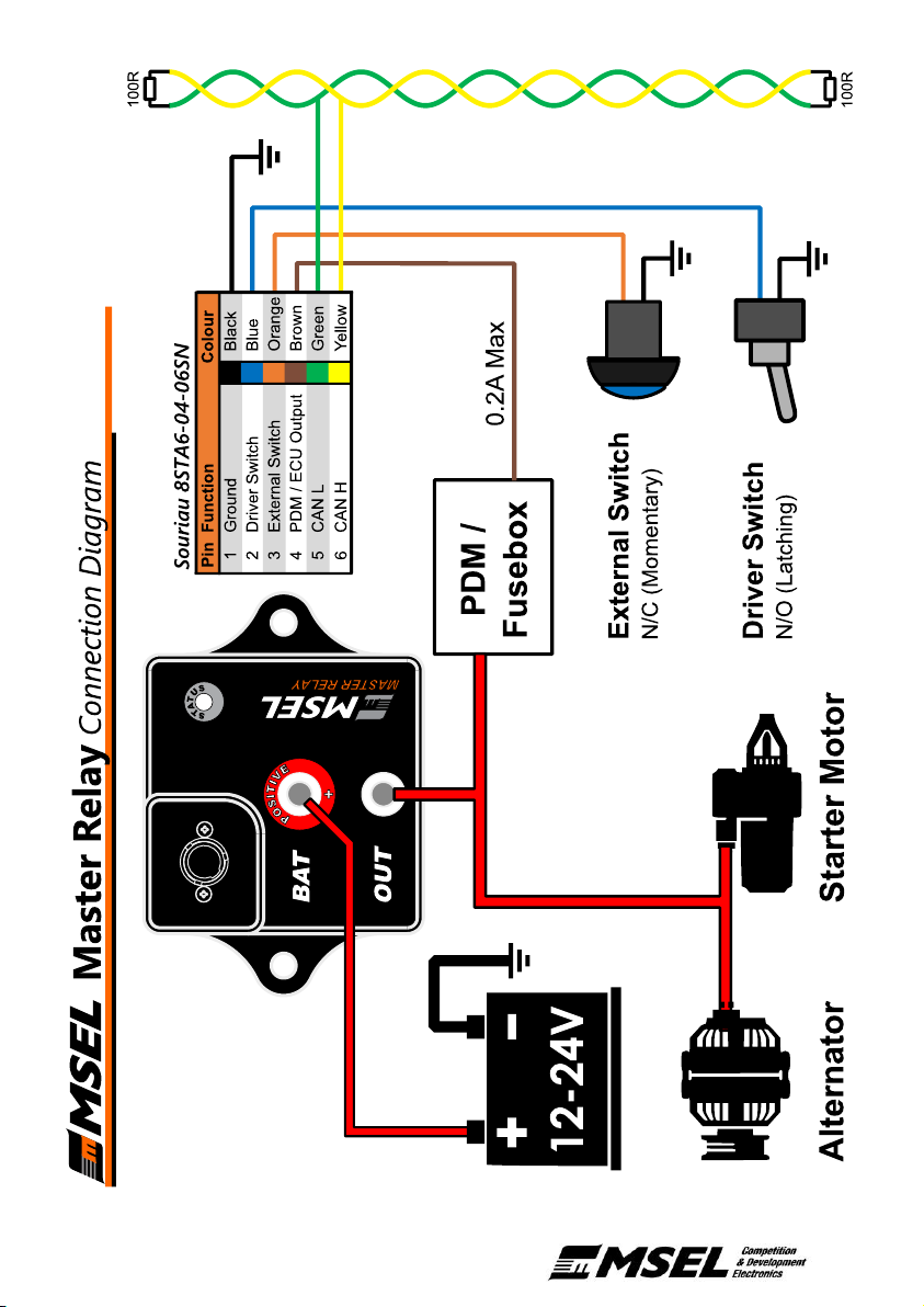
Figure 1: Connection Diagram
Page 5
Master Relay - User’s Manual 3
Installation
Mounting
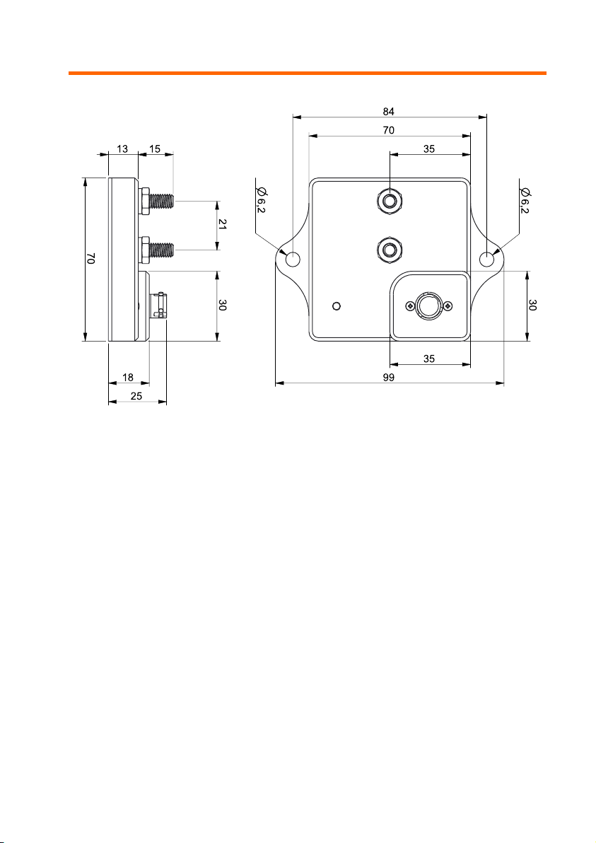
The MSEL Master Relay has two tags designed for mounting the device to a flat surface. The
spacing between the mounting holes is 84mm (see Drawing for details). The location of the
Master Relay, as well as the total current load, can have significant effect on the internal
temperature of the Master Relay. Where possible try to mount the Master Relay away from
significant heat sources.
Electrical Connection
The Master Relay is connected between the positive terminal of the battery and the rest of
the vehicles positive power supply. The device should be positioned as close to the battery
as possible, keeping the positive lead as short as you can. See the Connection Diagram for
a typical installation.
ENSURE THAT THE GROUND CONNECTION IS MADE BEFORE CONNECTING THE
BATTERY AND VEHICLE TERMINALS.
Power Studs
The battery and output terminals are copper plated M6 studs. Care should be taken to
ensure that cables are insulated from the housing and neighbouring studs. It is
recommended to use the supplied nut caps with insulated lugs, or for maximum
protection, rubber insulating boots can be used on each stud.
Interface Connector
All low current connections are made through a single 6-way Souriau mil-spec connector;
keeping things tidy, protected and allowing for quick removal / installation.
The mating connector (Souriau 8STA6-04-06SN) can be purchased individually for
custom installs or a breakout harness with DTM connectors is available for generic
installs.
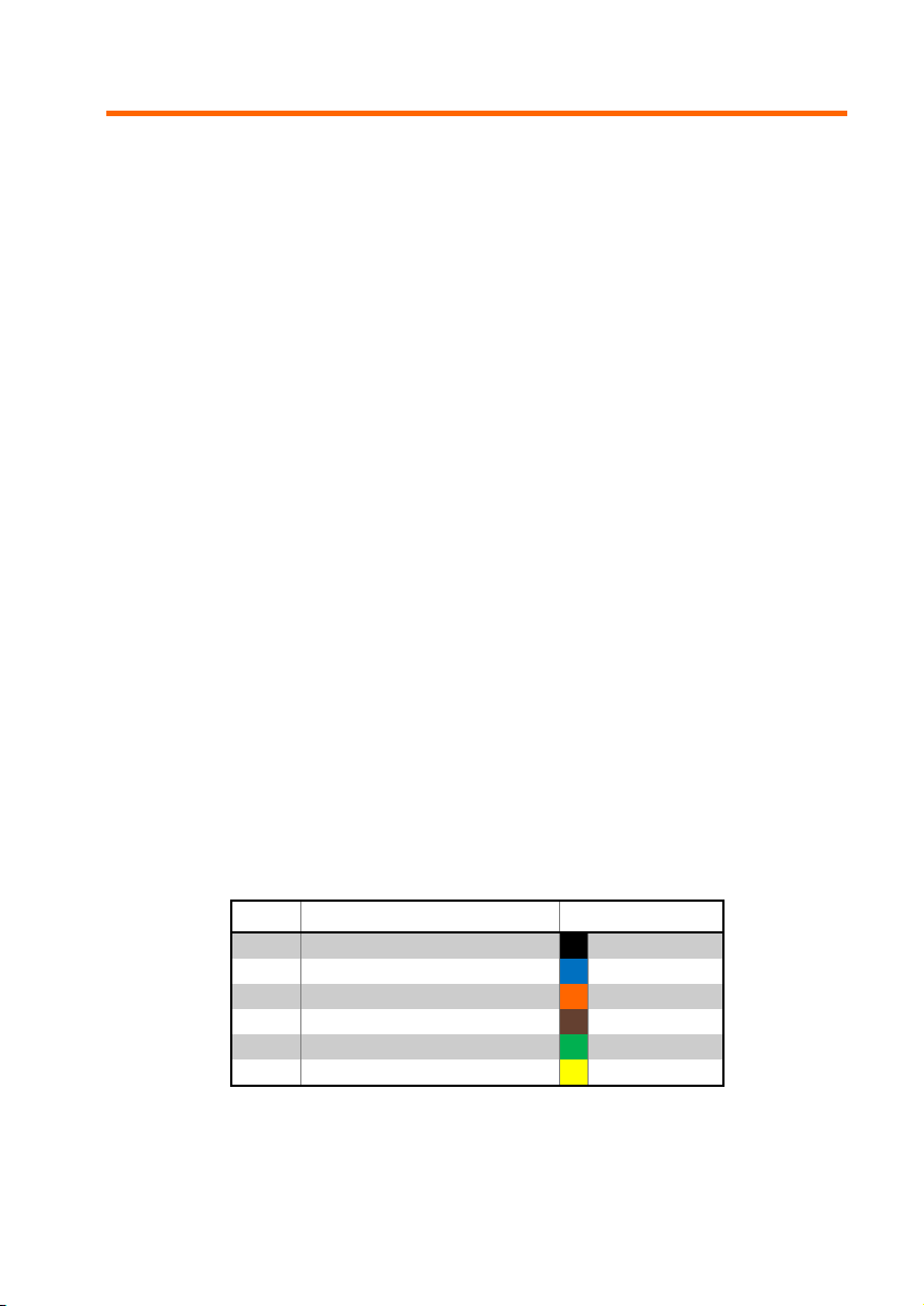
Table 1: Interface connector pinout
Pin
Function
Colour
1
Ground Black
2
Driver Switch
Blue
3
External Switch
Orange
4
PDM / ECU Output
Brown
5
CAN L Green
6
CAN H Yellow
Table 1 shows the pinout along with the standard wiring colours supplied with the breakout
harness. For those making a custom harness the Souriau connector has #26 terminals
and accept 30AWG through to 24AWG wire.
Page 6
4
Switch Connection
The Master Relay is controlled by two types of switch, the driver kill switch and the external
kill switch.
Driver Kill Switch
The driver kill switch is generally operated from within the vehicle and is the main control
for the battery isolation. Generally, just a single driver kill switch is used, however multiple
switches can be wired as shown in Multiple Switches, the extra switch could be hidden
and used as an additional security measure.
Wiring of the driver kill switch is carried out as shown in the Connection Diagram. The
switch used should be of a latching type (either toggle or push button). When the switch
is in the off position there should be an open circuit between the two terminals. One side
of the switch connected to pin 2 of the Master Relay connector, and the other side is
connected to ground.
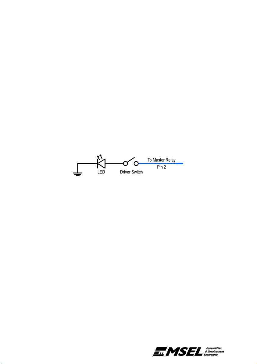
An LED can be added to the circuit as shown in Figure 2. This LED will be on solid when
the device is in the normal state, flash when the battery is isolated, and be turned off when
the driver switch is off.
Figure 2: LED indicator wiring
External Kill Switch
The external kill switch allows remote triggering of the Master Relay. It is often mounted
on the exterior of the vehicle and indicated by a red lightning bolt on a blue triangle.
Multiple external switches can be wired as shown in Multiple Switches. If an external
switch is not required, pin 3 of the Master Relay connector should be permanently
connected to ground.
Wiring of the external kill switch is carried out as shown in the Connection Diagram. The
switch used should be of a momentary non-latching type with a normally closed (NC)
configuration. When the switch is pressed there should be an open circuit between the
two terminals. One side of the switch is connected to pin 3 of the Master Relay connector,
and the other side connected to ground.
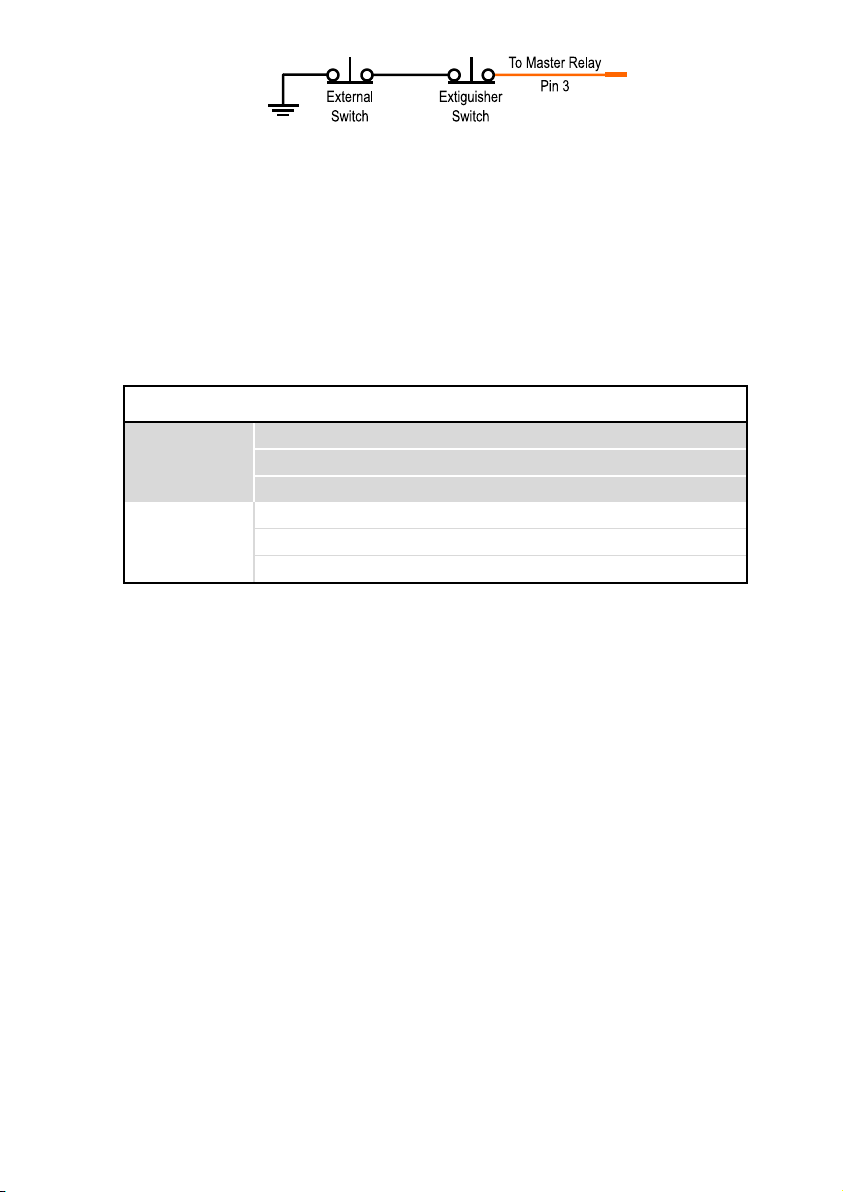
Multiple Switches
Multiple external kill switches can be connected in series provided that when all switches
are in the ‘ON’ position there is continuity between the input to the Master Relay and
ground. When any switch is in the ‘OFF’ position the connection to ground should be open
circuit. See Figure 3 for examples of multiple switch configurations.
Page 7
Master Relay - User’s Manual 5
Figure 3: Example multiple external switch configuration
PDM / ECU Connection
Pin 4 of the Master Relay connector provides a logical output for a PDM / ECU allowing engine
shutdown functionality in accordance with FIA rules. The drive of this output can be configured
in the combinations shown in Table 2 below. The device ships standard with configuration 0
(active high, half bridge). In this configuration when the Master Relay is in an ‘On’ or ‘Normal’
state the output is connected to the battery supply, and when ‘Off’ the output is connected to
ground.
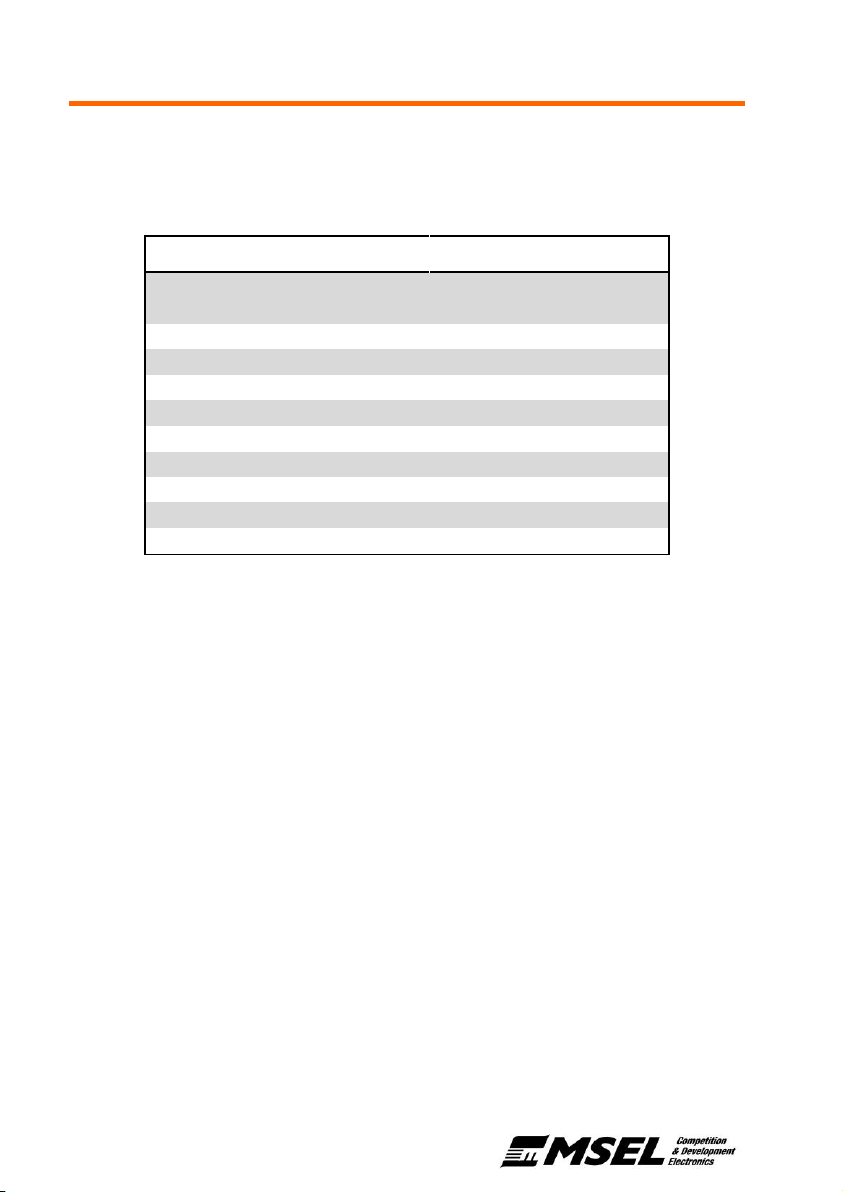
Table 2: PDM output drive configurations
Active State
Output Drive
Config.
Output 'On'
Output 'Off'
High
Half Bridge
0
V
battery
GND
Low Side 2 -
GND
High Side
1
V
battery
-
Low
Half Bridge
4
GND
V
battery
Low Side 6 GND
-
High Side 5 -
V
battery
In order to change the output drive to one of the other configurations please refer to Changing
the PDM Output Drive Configuration, or specify your requirements when purchasing.
The PDM / ECU output is short circuit protected and current limited to 200mA. To drive larger
loads an external relay is recommended.
CAN Bus Connection
To receive status and channel information from the Master Relay it must be connected to a
compatible device on the same CAN bus. Examples of these include a data logger, dash
display, or ECU. The Master Relay transmits two messages on a configurable address and is
compatible with most CAN capable data loggers on the market. For further information on the
format and transmission refer to the CAN Communications section.
The Master Relay does not have any internal termination resistors and therefore requires
100R termination resistors at each end of the CAN bus.
Page 8
6
Master Relay States
LED Indicator States
The table below shows the corresponding states for each of the possible colour codes
displayed on the status LED.
Table 3: LED indicator states
Status
LED Colour
Normal
Green
(CAN Error)
/
Green Flashing
Over Temperature Warning
/
Blue Flashing
Over Current Kill
Yellow
Low Voltage Warning
/
Green/Blue Flashing
High Voltage Warning
/
Green/Red Flashing
Over Temperature Kill
/
Blue/Red Flashing
Driver Switch Kill
Red
External Switch Kill
/
Red Flashing
CAN Trigger Kill
Blue
Power On Reset
Purple
Battery Connected
Normal Operation
The battery is connected to the output and the device is operating normally.
Normal Operation (CAN Error)
The device is operating normally; however, the CAN bus has been unresponsive for more
than 2 transmission cycles. CAN communications have been disabled until the CAN bus
is back online (this is checked every 5 seconds).
Over Temperature Warning
The device temperature has exceeded the warning temperature (90°C). The device will
continue to function normally; however, the temperature is getting close to the device
limits. This should be remedied to avoid undesired performance and/or potential damage.
Once the fault is remedied the device will automatically return to normal operation.
Low Voltage Warning
The device voltage has dropped below the lower warning limit (7V). The device will try to
continue to function normally, however the voltage is getting close to the device limits.
This should be remedied to avoid undesired performance and/or potential damage.
Once the fault is remedied the device will automatically return to normal operation.
Page 9

Master Relay - User’s Manual 7
High Voltage Warning
The device voltage has exceeded the upper warning limit (28V). The device will try to
continue to function normally, however the voltage is getting close to the device limits.
This should be remedied to avoid undesired performance and/or potential damage.
Once the fault is remedied the device will automatically return to normal operation.
Battery Isolated
Driver Kill
The driver kill switch has been turned off or the connection has broken. The battery is
disconnected and the indicator will be solid red.
The device will remain in this state for 30 seconds before entering a low power state. To
return to normal operation a reset is required (see Resetting the Device).
External Kill
The external kill switch has been triggered or the connection has broken. The battery is
disconnected and the indicator will be flashing red.
To return to normal operation a reset is required (see Resetting the Device).
CAN Kill
A CAN message has triggered a shutdown. The battery is disconnected and the indicator
will be solid blue. See CAN Shutdown for further details on the CAN kill function.
To return to normal operation a reset is required (see Resetting the Device).
Over Temperature Kill
The device temperature has exceeded the maximum allowed temperature (110°C). The
battery is disconnected and the indicator will be flashing red and blue.
Once the fault is remedied the device will automatically return to normal operation.
Power On Reset
The device has been powered on with the driver & external switches on. The battery
remains disconnected and the indicator will be solid purple.
To return to normal operation a reset is required (see Resetting the Device).
Over Current Kill
The device temperature has exceeded the maximum allowed current. The battery is
disconnected and the indicator will be solid yellow.
Check for any short circuits between the output terminal and the chassis ground. To return
to normal operation once the fault is remedied, a reset is required (see Resetting the
Device).
Page 10

8
Resetting the Device
Once the device has been triggered by one of the 5 faults (external kill, driver kill, CAN kill,
over-current kill or over-temperature kill) the device will remain in the off state until reset. The
LED indicator will show the current fault as outlined in LED Indicator States.
Once the fault has been remedied the device can be reset by cycling the driver kill switch off
and then back on.
Load Dump Protection
The Master Relay has on board circuitry that will help protect sensitive electronic devices in
the event of a shutdown during engine operation. The PDM output will be turned off
immediately therefore stopping the engine. However, the battery is not disconnected until the
alternator is no longer charging. This avoids the situation where the alternator may still be
generating as the battery is disconnected, resulting in voltage spikes as large as 120V that
can damage sensitive electronic components.
The Master Relay has a 5 second timeout where by even if for some reason the battery is still
being charged it will be disconnected regardless (this can be extended by specifying a longer
shutdown delay, see Shutdown Delay).
Shutdown Delay
The Master Relay can be programmed to delay switching the battery power off to allow for
diagnostic data logging. The shutdown delay is in addition to the load dump protection delay
described in Load Dump Protection. Therefore, the battery is guaranteed to be connected for
the duration of the shutdown delay, except for an over current event where the battery is
disconnected immediately to prevent potential damage.
The recommended procedure for this is to use a PDM or ECU to shut down the engine and
disable everything except the data logging systems. This allows these devices to receive the
shutdown event information and store it before shutting down.
The table below indicates the recommended delay times for different data logging systems:
Table 4: Recommended shutdown delay times
Data Logging Device
Shutdown Delay
All MoTeC products
1.0 seconds
All devices are shipped with no additional shutdown delay, in order to activate this feature
please request it at the time of purchase, or program the desired delay as described in
Changing the CAN Baud Rate & Shutdown Delay.
Page 11

Master Relay - User’s Manual 9
Temperature Monitoring
The Master Relay has an on-board temperature sensor for monitoring the internal
temperature of the unit. The temperature is transmitted on the CAN bus as well as used
internally to isolate the battery in case of excessive temperatures. A warning is displayed on
the LED indicator at 90°C (flashing blue) and the device is shut down at 110°C with a blue/red
indication on the LED.
The device will automatically attempt to restart when the temperature drops back down below
100°C, or with a device reset (and temperature is below 110°C).
Load Current Monitoring
The Master Relay has internal bi-directional current sensing for the load to / from the battery.
This current is transmitted as part of message 1 on the CAN bus (see CAN Communications).
The load current is designed as an indication of the total system draw and is accurate to ±10%
or 1A (whichever is greatest). It is not intended to be used for detailed, smaller current draw
analysis. The Master Relay should be used in conjunction with a PDM for accurate
measurement of current for individual devices.
The Master Relay has integrated short-circuit protection and will isolate the battery in the
event of a major short circuit on the main output terminal.
Power Saving Mode
After 30 seconds in the Driver Kill mode the Master Relay will enter a power saving mode. In
this mode the following functions of the device are turned off to save power.
• CAN transmission is disabled
• The LED indicator is turned off
• Temperature and load monitoring are turned off
• The microcontroller is put into a standby state
The device resumes operation as soon as the driver switch is turned on again.
Page 12
10
CAN Communications
The Master Relay comes preprogramed with a baud rate of 1 Mbps. The user can configure
the device to a baud rate of 500 Kbps or 250 Kbps as detailed in Changing the CAN Baud
Rate & Shutdown Delay, or alternatively request these settings at the time of purchase.
Message Format
The Master Relay transmits status and information on the CAN bus over two addresses.
These addresses are defined by the base CAN address (Default: 0x6E4). This can be
configured using the process detailed in Changing the base CAN Identifier, or alternatively by
requesting a particular address at the time of purchase.
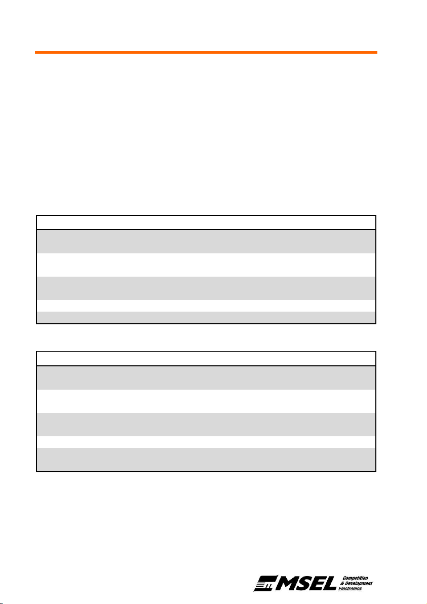
Table 5 & Table 6 below show the format of the transmitted channels. Each message is
transmitted at a rate of 10Hz, and all multi-byte channels are in Big-Endian format (MSB first).
Table 5: Base address (Default: 0x6E4)
Byte
Channel
Units
Length
Base
Signed
Value
Transmitted
0
Voltage Out
V 2 0.01
Unsigned
12.56
1256
1
2
Current Load
A 2 0.1
Signed
54.5
545
3
4
Internal Temperature
°C 2 0.1
Signed
25.2
252
5 6 Warnings
- 1 1 - see
(2)
7
Status
- 1 1 - see
(1)
Table 6: Base address + 1 (Default: 0x6E5)
Byte
Channel
Units
Length
Base
Signed
Value
Transmitted
0
Voltage In
V 2 0.01
Unsigned
12.56
1256
1
2
Serial No.
- 2 1
Unsigned - -
3
4
Configuration
(3)
- 2 1
Unsigned - -
5 6 Time Since Shutdown
s 1 0.1
Unsigned
15.5
155
7
Shutdown Cause 2
(4)
-
4 MSB 1 -
see
(1)
Shutdown Cause
(4)
-
4 LSB 1 -
see
(1)
(1
) List of ‘Status’ enumerations are available in Table 7
(2)
‘Warning’ bit masks are available in Table 7
(3)
‘Configuration’ composition is available in Table 8
(4)
‘Shutdown Cause 1’ is the 2nd to last event, and ‘Shutdown Cause 2’ is the last event (from serial no. 61061),
serial no. prior to 61061 just give last event.
Page 13
Master Relay - User’s Manual 11
Status and Warning Formats
The status and warning channels transmitted in CAN message 1 contain the current
status of the warnings and faults on the device. The status enumerations are listed in
Table 7 below.
The warning channel is made up from 8 individual bits, corresponding to the status or
switch states. Multiple warnings may be present at any single instance. For example, if
both the external switch (0x40) and the driver switch (0x20) are off, the warning channel
will be equal to 0x60.
Table 7: Status enumeration & warning channel bit masks
Status
Status
Enumeration
Warning
Bit Mask
Normal 1 -
Over Temperature Warning
2
0x01
Over Current Warning
3
0x02
Low Voltage Warning
4
0x04
High Voltage Warning
5
0x08
Over Temperature Kill
6
0x10
Driver Switch Kill
7
0x20
External Switch Kill
8
0x40
CAN Trigger Kill
9
0x80
Power On Reset
10
-
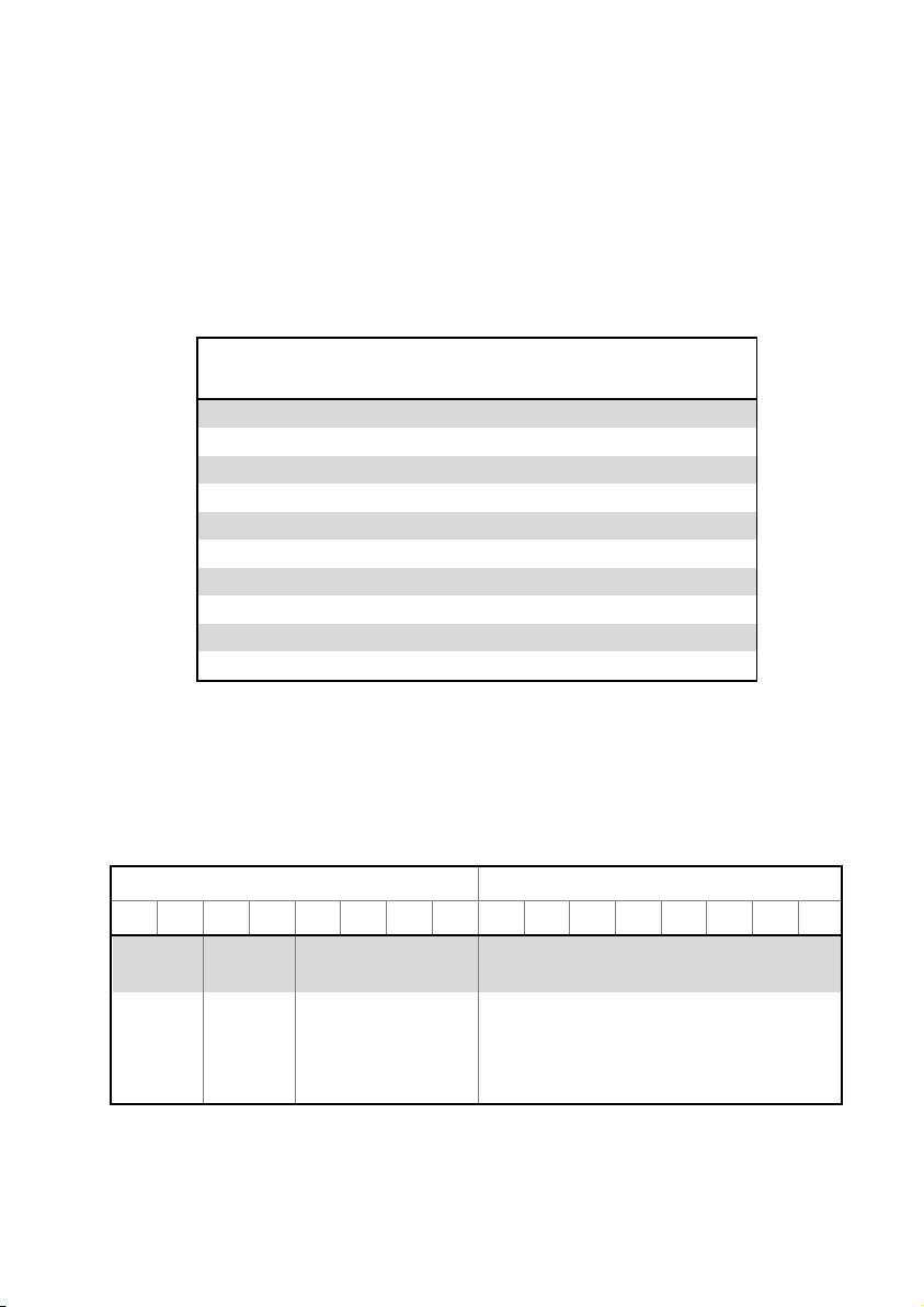
Configuration Format
The configuration channel contains information on the current configuration stored in the
Master Relay. Table 8 below shows the composition of this channel from the features
programmed as detailed in Device Configuration.
Table 8: Configuration channel composition
Byte 1
Byte 2
7 6 5 4 3 2 1 0 7 6 5 4 3 2 1
0
CAN Kill
Enable
CAN Baud
Rate
Output Drive
Shutdown Delay
0 = Disabled
1 = Enabled
2 = ADR
0 = 1Mbps
1 = 500Kbps
2 = 250Kbps
0 = Active-Hi, Half Bridge
1 = Active-Hi, High Side
2 = Active-Hi, Low Side
4 = Active-Lo, Half Bridge
5 = Active-Lo, High Side
6 = Active-Lo, Low Side
Shutdown Delay (in 0.1 seconds)
eg. 10 = 1 second shutdown delay
Page 14
12
CAN Shutdown
The Master Relay has the ability to be shut down remotely via a CAN message. As default
this functionality is disabled. Refer to Setting up CAN Shutdown for information about how to
enable and set up this function, or alternatively request this functionality to be programmed
when ordering the device.
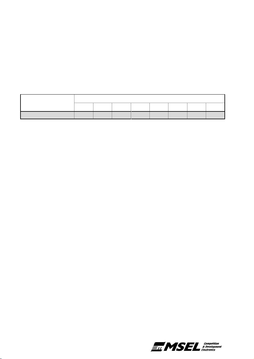
When enabled, upon receiving a message with the format shown in Table 9, and on the
configured CAN kill address, the Master Relay will shut down the engine and isolate the
battery.
Table 9: Example CAN shutdown message for CAN Kill address 0x6E6
Received Address
Byte
0 1 2 3 4 5 6
7
0x6E6
0xFF
0x00
0xFF
0x00
0xFF
0x00
0xFF
0x00
This feature can also be programmed to work with a MoTeC Accident Data Recorder (ADR)
and trigger after a severe event. To enable this feature set the CAN Kill Enable byte to ‘2’,
and the CAN Kill address to the address of the status information transmitted by the ADR
(default is 0x449). See Setting up CAN Shutdown for further instructions.
Please check previous logged data carefully to ensure that the severe event
threshold in the ADR doesn’t false trigger on normal impacts such as ‘curb strikes’.
Page 15
Master Relay - User’s Manual 13
Device Configuration
Changing the base CAN Identifier
The default base CAN address is 0x6E4, can be changed using any CAN bus interface device
capable of transmitting a message onto the CAN bus. The following procedure changes the
CAN identifier on the Master Relay:
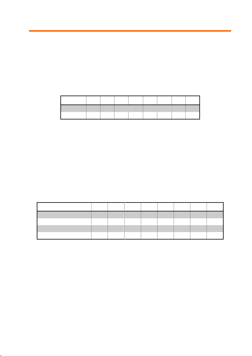
1. Configure the CAN interface device to transmit a single message on address 0x789
with the following format:
Table 10: Example CAN ID configuration message
Byte 0 1 2 3 4 5 6 7
Data
0x07
0x89
CAN_ID
CAN_ID
0x07
0x89
Example*
0x07
0x89
0x06
0xE4
0x06
0xE4
0x07
0x89
* shows the correct message format to change the address to 0x6E4
Where ‘CAN_ID’ is the desired new CAN address in big endian format (MSB first).
Please note that the CAN address must not exceed a length of 11 bits (0x000 to
0x7FF), and must not conflict with any other CAN devices on the network.
2. Press and hold the external kill switch while sending the above message.
3. The Master Relay will send a response message on the base CAN address. See
Table 11 for a list of responses.
Table 11: Responses for CAN ID configuration
0 1 2 3 4 5 6 7
Successful
0x00
0x00
0x00
0x00
0x00
0x00
0x00
0x00
IDs do not match
0x11
0x11
0x11
0x11
0x11
0x11
0x11
0x11
Frame check error
0x22
0x22
0x22
0x22
0x22
0x22
0x22
0x22
Invalid ID
0x33
0x33
0x33
0x33
0x33
0x33
0x33
0x33
4. After a successful response the Master Relay will be configured to send all CAN
information on the new base address.
Page 16
14
Changing the CAN Baud Rate & Shutdown Delay
The device comes preconfigured with a default CAN baud rate of 1Mbps, and a shutdown
delay of 200ms. These values can be changed using any CAN bus interface device capable
of transmitting a message onto the CAN bus. The following procedure is used to change the
CAN baud rate and shutdown delay on the Master Relay:
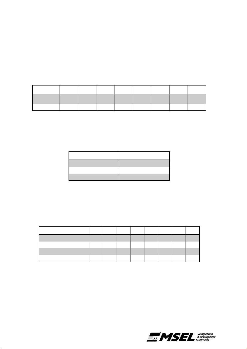
1. Configure the CAN interface device to transmit a single message on address 0x789
with the following format:
Table 12: Example CAN baud rate & shutdown delay configuration message
Byte 0 1 2 3 4 5 6 7
Data
0x04
0x56
BAUD
RATE
BAUD
RATE
SHUT
DELAY
SHUT
DELAY
0x04
0x56
Example*
0x04
0x56
0x01
0x01
0x0A
0x0A
0x04
0x56
* shows the correct message format to set the baud rate to 500Kbps and the shutdown delay to 1 second.
Where ‘BAUD RATE’ is from the table below and ‘SHUT DELAY’ is the delay in
tenths of a second that the power is kept on after a shutdown event (in hex).
Table 13: List of baud rate enumerations
Baud Rate Value
‘BAUD RATE’
1Mbps (Default)
0x00
500Kbps
0x01
250Kbps
0x02
2. Press and hold the external kill switch while sending the above message.
3. The Master Relay will send a response message on the base CAN address. See
Table 14 for a list of responses.
Table 14: Responses for CAN baud rate & shutdown delay configuration
0 1 2 3 4 5 6
7
Successful
0x00
0x00
0x00
0x00
0x00
0x00
0x00
0x00
Values do not match
0x11
0x11
0x11
0x11
0x11
0x11
0x11
0x11
Frame check error
0x22
0x22
0x22
0x22
0x22
0x22
0x22
0x22
Invalid baud rate
0x33
0x33
0x33
0x33
0x33
0x33
0x33
0x33
4. After a successful response the Master Relay will need to be restarted (by removing
the power) before the new CAN baud rate is implemented. The shutdown delay is
effective immediately.
Page 17
Master Relay - User’s Manual 15
Changing the PDM Output Drive Configuration
The device comes preconfigured with a default PDM drive output of active high, half-bridge.
This configuration can be changed using any CAN bus interface device capable of
transmitting a message onto the CAN bus. The following procedure is used to change the
PDM output drive on the Master Relay:
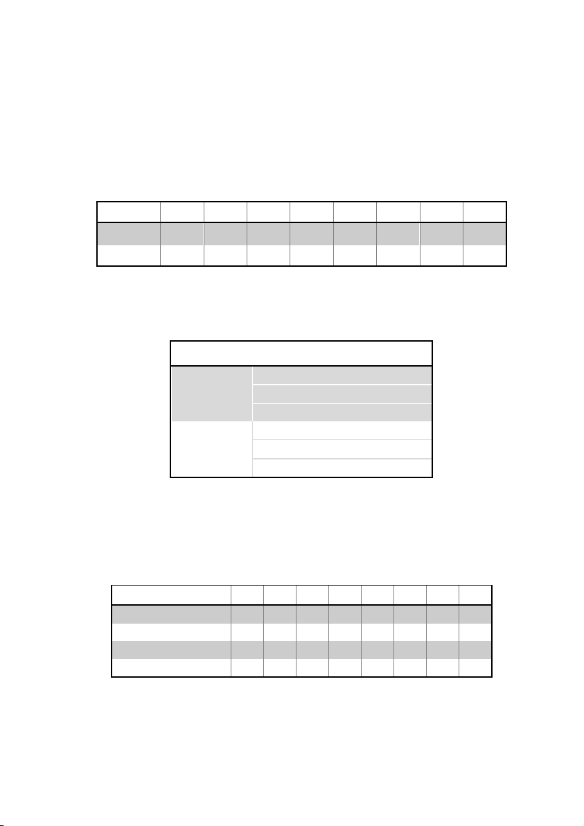
1. Configure the CAN interface device to transmit a single message on address 0x789
with the following format:
Table 15: Example PDM output drive configuration message
Byte 0 1 2 3 4 5 6 7
Data
0x0A
0xBC
OUTPUT
DRIVE
OUTPUT
DRIVE
0x00
0x00
0x0A
0xBC
Example*
0x0A
0xBC
0x06
0x06
0x00
0x00
0x0A
0xBC
* shows the correct message format to set the PDM output drive to active low, low side.
Where ‘OUTPUT DRIVE’ is selected from the table below:
Table 16: List of output drive enumerations
Active State
Drive
‘OUTPUT DRIVE’
High
Half Bridge
0x00
Low Side
0x02
High Side
0x01
Low
Half Bridge
0x04
Low Side
0x06
High Side
0x05
2. Press and hold the external kill switch while sending the above message.
3. The Master Relay will send a response message on the base CAN address. See
Table 17 for a list of responses.
Table 17: Responses for PDM output drive configuration
0 1 2 3 4 5 6
7
Successful
0x00
0x00
0x00
0x00
0x00
0x00
0x00
0x00
Values do not match
0x11
0x11
0x11
0x11
0x11
0x11
0x11
0x11
Frame check error
0x22
0x22
0x22
0x22
0x22
0x22
0x22
0x22
Invalid configuration
0x33
0x33
0x33
0x33
0x33
0x33
0x33
0x33
4. After a successful response, the Master Relay will need to be reset before the new
PDM output drive is implemented.
Page 18
16
Setting up CAN Shutdown
The CAN shutdown function is disabled by default. This configuration can be changed using
any CAN bus interface device capable of transmitting a message onto the CAN bus. The
following procedure enables / disables the CAN shutdown function of the Master Relay, as
well as sets the address for shutdown commands to be received. For more information on
how to use the shutdown once enabled, please refer to Configuration Format.
1. Configure the CAN interface device to transmit a single message on address 0x789
with the following format:
Table 18: Example CAN shutdown configuration message
Byte 0 1 2 3 4 5 6 7
Data
0x01
0x23
CAN_KILL
CAN_KILL
0x01
0x23
Example*
0x01
0x23
0x16
0xE6
0x16
0xE6
0x01
0x23
* shows the correct message format to enable CAN shutdown on address 0x6E6
Where ‘CAN_KILL’ is composed as in Table 19 below. The first 4 bits (‘EN’), set the
CAN shutdown mode, where 0 is disabled, 1 is enabled, and 2 is for a MoTeC ADR.
The last 12 bits (‘KILL_ID’) set the receive CAN address in big endian format (MSB
first).
Table 19: Example ‘KILL_ID’ composition
Byte 0 1
Mask
0xF0
0x0F
0xF0
0x0F
Data
EN
KILL_ID
Example*
0x1
0x6
0xE
0x6
* shows the correct byte composition to enable CAN shutdown on address 0x6E6
‘EN’ must be less than 0x2 to enable the function. Setting ‘EN’ to any other value
will disable the CAN shutdown function.
Please note that the CAN address must not exceed a length of 11 bits (0x000 to
0x7FF), and must not conflict with any other CAN devices on the network.
2. Press and hold the external kill switch while sending the above message
The Master Relay will send a response message on the base CAN address. See Table 20
for a list of responses.
Page 19

Master Relay - User’s Manual 17
Table 20: Responses for CAN ID configuration
0 1 2 3 4 5 6 7
Successfully Enabled
0x00
0x00
0x00
0x00
0x00
0x00
0x00
0x00
IDs do match
0x11
0x11
0x11
0x11
0x11
0x11
0x11
0x11
Frame check error
0x22
0x22
0x22
0x22
0x22
0x22
0x22
0x22
Set to ADR Mode
0x55
0x55
0x55
0x55
0x55
0x55
0x55
0x55
Successfully Disabled
0x66
0x66
0x66
0x66
0x66
0x66
0x66
0x66
3. After a successful response, the Master Relay will need to be restarted (by
removing the power) before the CAN shutdown is enabled.
Page 20

18
Specifications
Connection
Battery Terminal: Copper Plated Stud M6
Output Terminal: Copper Plated Stud M6
Mating Interface Connector: 8STA6-04-06SN
Pin 1: Ground
Pin 2: Driver Switch
Pin 3: External Switch
Pin 4: PDM / ECU Output
Pin 5: CAN Low
Pin 6: CAN High
Power Supply
Operating Voltage: 8 to 30 V
Operating Current: 0.03 A (Normal)
0.02 A (Isolated)
0.001 A (Power saving)
Operating Conditions
Temperature: -20 to 100 °C
IP Rating: IP63
PDM / ECU Output
Drive Type: Configurable, (see PDM / ECU Connection)
Output Voltage: V
battery
Max Current: 200mA (maintained)
Switched Current
Maintained Current: 200 A
Peak Current: 1000 A
Current Measurement
Sensitivity: 0.5 A (Up to 100A)
5.0 A (Over 100A)
Calibration Error: ±10% or 1 A
Range: -255 to 600 A
Temperature Measurement
Sensitivity: 0.2 °C
Calibration Error: ± 3°C
Range: 0 to 125°C
CAN Bus
Baud Rate: Configurable (Default: 1Mbps)
Transmit Addresses: Configurable (Default: 0x6E4, 0x6E5)
Termination Resistor: External required
Physical
Mass: 115 g
Page 21
Master Relay - User’s Manual 19
Drawing
All dimensions are in mm
Page 22

20
Revision History
v1.0 – November 2016
Serial No. up to 61060
Initial Release
v1.1 – October 2017
Serial No. 61061 on
Added ‘2nd Shutdown Cause’ to the CAN messaging. This gives the last two reasons for
shutdown, allowing logging the original shutdown event to be seen, even after a ‘reset’.
Page 23

Master Relay - User’s Manual 21
Page 24

Copyright © 2017 – Motorsport Electronics Ltd
Master Relay User’s Manual
Rev 1.1, October 2017
www.msel.com | [email protected] | +64 9 525 2991
 Loading...