

Page 1
MSD Advanced RPM Control Module
PN 7761
ONLINE PRODUCT REGISTRATION: Register your MSD product online and you’ll be entered in our
monthly 8.5mm Super Conductor Spark Plug Wire give-away! Registering your product will help if there
is ever a warranty issue with your product and helps the MSD R&D team create new products that you
ask for! Go to www.msdignition.com/registration.
Parts Included:
1 - Module
1 - Parts Bag
Required Items for Operation:
MSD Power Grid - PN 7730
MSD CAN-Hub - PN 7740
The Advanced RPM Control Module (ARC), PN 7761, has been designed to help prevent excessive
wheel speed. In the event that engine and / or driveshaft rpm increase(s) at an undesirable rate the
module’s software will retard timing and/or rev limiting in order to prevent excessive wheel speed.
INSTALLATION:
The ARC Module should be securely mounted near the MSD CAN-Hub. Plug the ARC CAN connector
to an available port on the MSD CAN-Bus Hub, PN 7740. Do NOT cut the CAN-Bus connector wires.
1 - 8’ DS Sensor extension harness
Hall Effect Sensor - Racepak PN 800-SS-MSC-5
Driveshaft Collar - Call Racepak
The driveshaft sensor must plug directly to the 7761 module. MSD recommends using an 8-magnet
driveshaft collar. Using less than an 8-magnet collar will result in less data for the processor to
work with and slower, less reliable corrections.
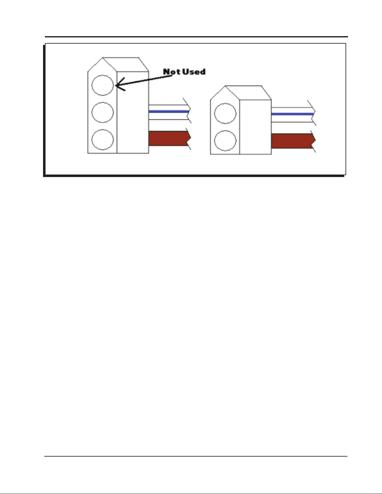
When connecting to a Racepak Data Recorder, the White/Blue and Brown wires will be connected
to the driveshaft input on the Racepak. The wires (White/Blue and Brown) do not have a connector
on them from the factory; two connectors are included in the parts bag of the module. Select and
install either the 2-pin or 3-pin connector depending on which style is required by the data recorder
being used. To install, push the pins (pre-installed on the wires) into the proper hole according to
Figure 1 below. If these wires are not used, terminate the wires using heat shrink so that they cannot
create a short.
The Yellow output wire is included in the same loom as the driveshaft output wires. The Yellow wire
will switch to ground any time the ARC is controlling timing or rev limiting. The output circuit can
support up to two amps continuous. This can be used to activate a light, solenoid, or boost controller.
M S D • W W W . M S D P E R F O R M A N C E . C O M • ( 9 1 5 ) 8 5 7 - 5 2 0 0 • F A X ( 9 1 5 ) 8 5 7 - 3 3 4 4
Page 2

2 INSTALLATION INSTRUCTIONS
MSD 7730 Wiring
Wire
Lead Grouping Color Function Description
6-PIN CONN (TO Hub / Modules) RED MSD CAN HI Supplie s 12V s witched powe r
to add on modul e un its. Also
communicates between modules
and Power Grid System Controller.
This connector is only used with
modules added onto the system.
BROWN SHIELD
RED POWER OUT
BLACK MSD CAN LO
BLACK MSD CAN GND
3-PIN CONN (DS to MSD) Green Ground These wires send the signal to the
MSD from the driveshaft sensor.
.
Purple / Blue Signal
Red Power
LOOSE WIRES Brown Ground These two wires should be inserted
(MSD to RACEPAK)
The connector must be assembled
using the two pin or three pin
connector to accommodate the
Racepak connector needed.
White / Blue Signal
Yellow Active Indicator Provides ground to a circuit any time
into one of the connectors supplied
in the parts bag as shown in Figure
1. These wires send the driveshaft
signal from the MSD to Racepak.
the unit is active by retarding or rev
limiting.
M S D • W W W . M S D P E R F O R M A N C E . C O M • ( 9 1 5 ) 8 5 7 - 5 2 0 0 • F A X ( 9 1 5 ) 8 5 7 - 3 3 4 4
Page 3
INSTALLATION INSTRUCTIONS 3
Figure 1 Installing 2-pin or 3-pin connector.
OPERATION
To program the ARC module start MSD View and connect to the 7761 with the ignition on.
• Turn on ignition power
• Connect 7730 to PC via USB
• Start MSD View
• In the Connect box select 7761
• Click “Connect”
MSD View will be display three main tabs; Settings, Driveshaft, and Crankshaft.
SETTINGS
This tab contains general settings for the ARC unit. After the items in this tab have been programmed
the first time they will not need to be changed unless hardware changes are made. The settings
available here are:
Driveshaft Input – Calibrates the signal from the driveshaft sensor. The unit accepts 2, 4, 8,
or 16 magnet DS collars.
Output to Racepak – Calibrates the signal sent to the Racepak unit. Refer to your Racepak
software or user manual to determine the proper signal for that system.
The unit can send a signal representing 2, 4, or 8 magnet DS collars.
Driveshaft Acquisition – Enable or disable the System Controller, PN 7730, from recording driveshaft
data.
DRIVESHAFT
If settings are entered for both Driveshaft and Crankshaft the module will limit accordingly for
both inputs.
Settings made to these sub tabs control the engine according to driveshaft speed.
M S D • W W W . M S D P E R F O R M A N C E . C O M • ( 9 1 5 ) 8 5 7 - 5 2 0 0 • F A X ( 9 1 5 ) 8 5 7 - 3 3 4 4
Page 4

4 INSTALLATION INSTRUCTIONS
RETARD ABOVE LIMIT
The settings in this sub tab determine the amount of timing retard based on time from launch. A slope
can be set if an engine needs less timing retard further into a run. Multiple steps can be plotted to
coordinate with gear changes or nitrous events. The settings here vary depending on the application.
Two lines can be programmed. The software is designed so that the lower line will always be the
maximum timing taken out. The top line will always be the minimum timing taken out. Because of
this, it makes no difference which line is above the other.
When the driveshaft rpm is between the Retard Curves the ARC module will automatically determine
timing change. The unit calculates the amount of timing change by interpolation. By using the
calculation, the module makes it progressively harder for the engine to continue accelerating past
the desired plot.
If only one retard setting is desired – with no progressive control – then both Retard Above Limit curves
should be set identically. If one line is left at the top of the plot, the software will see the minimum
retard as zero.
CURVES
There are up to three curves to set in this tab; two Retard Curves and a single Limiter Curve. The
three lines can be combined or used individually for only retard or only limiter. Typically, one Retard
Curve will be set to follow the driveshaft rpm curve closely. The other Retard Curve will be plotted
above. The Limiter Curve is a safety by plotting above the highest Retard Curve. When driveshaft
speed exceeds the Rev Limiter Curve the ARC module will clamp the engine at the engine rpm that
was present when the driveshaft speed exceeded the plot. The engine rpm clamp will be released
after the driveshaft speed drops below the plot. Each curve set can be programmed with up to 30
points in intervals of 0.01 seconds and 1 rpm. See “Loading Curves” below for instructions to import
a driveshaft curve into this plot.
CRANK SHAFT
If settings are entered for both Driveshaft and Crankshaft the module will react accordingly for
both inputs.
Settings made to these sub tabs control the engine according to crankshaft rpm. There is sometimes
a lag between driveshaft and crank shaft inputs, this is especially true in vehicles with automatic
transmissions due to the convertor.
SLEW RATE
The ARC Module can control the engine RPM when it exceeds the pre determined acceleration.
During excessive acceleration, the ARC Module can be programmed to retard timing or to rev limit
the engine speed. MSD ReView can be used to determine the slew rate and assist in slew settings.
On the Engine RPM trace of any file within View the slew rate is calculated for the time between the
red and blue cursors. It is best to put the cursors at the top and bottom of the steepest area of a good
run to get a starting point of an engine’s slew.
A margin must be set since all RPM curves experience some variances (“wobble” - jagged lines due
to split second changes in speed). The margin programmed in RPMs allows for excessive slope in
the slew rate for a short period of time. Without the margin, or when the margin is set too low, the
module may limit the engine each time there is an upswing in the normal variance (rpm “wobble”).
If margin is too large, the slew controller will not activate early enough to control rapid acceleration.
The default Margin is set to 200 rpm.
M S D • W W W . M S D P E R F O R M A N C E . C O M • ( 9 1 5 ) 8 5 7 - 5 2 0 0 • F A X ( 9 1 5 ) 8 5 7 - 3 3 4 4
Page 5

INSTALLATION INSTRUCTIONS 5
Crank Slew Limiter - Use this setting to turn slew rate control ON or OFF.
Launch Delay Time - Preset the amount of time after the Dark Blue launch wire is released. In that
time no corrections will be made for high slew rate.
Timing Margin - The excess rpm allowance for fluctuations (“wobble”) in the engine’s speed.
This is necessary because of the variance seen in RPM signal. This margin
sets the minimum amount of RPM climb required to activate the timing control
features.
Rev Limit Margin - The excess rpm allowance for fluctuations (“wobble”) in the engine’s speed.
This is necessary because of the variance seen in RPM signal. This margin
sets the minimum amount of RPM climb required to activate the rev limit
features. This margin always acts in addition to Timing Margin.
Slew Retard - The retard amount activated while the Engine RPM exceeds the set Slew Rate
plus the Timing Margin.
Gear 1 - The maximum slew rate the system allows for each gear. The number of gears
that appear on the screen should match the number of gears programmed
into the 7730.
TIME BASED
The settings here work in the same way of those for the Driveshaft settings. Unlike the driveshaft
settings, the crank shaft settings allow only a single Retard Curve.
RETARD ABOVE LIMIT
The settings in this sub tab determine the amount of timing retard based on time from launch. A slope
can be set if an engine requires less timing retard further into a run. Multiple steps can be plotted to
coordinate with gear changes or nitrous events. The settings here vary depending on the application.
Only a single Retard Curve can be set based on Crank Shaft RPM.
CURVES
The Retard Curve or limiter Curve (AKA Dots) will be set to follow the crankshaft rpm curve closely.
When crankshaft rpm exceeds the Rev Limiter Curve the ARC module will limit the engine. If a retard
curve is used the timing will retarded accordingly. Each curve set can be programmed with up to 30
points in intervals of 0.01 seconds and 1 rpm. See “Loading Curves” below for instructions to import
a driveshaft curve into this plot.
FEATURES
There are a number of features of the software for the ARC module that do not have individual tabs.
LOADING RPM CURVES
In order to draw the best possible control curves for the ARC, users should import an RPM curve
from data recordings to use as a base. To load an RPM curve into this plot, a user must have a .csv
file from a previously recorded run. MSD View will accept up to 10 seconds worth of rpm data that
automatically loads from the 0 time point. If a run has data recorded prior to the launch, adjust the 0
time point with the Time Offset feature in ReView prior to transferring the run back into the View software.
M S D • W W W . M S D P E R F O R M A N C E . C O M • ( 9 1 5 ) 8 5 7 - 5 2 0 0 • F A X ( 9 1 5 ) 8 5 7 - 3 3 4 4
Page 6

6 INSTALLATION INSTRUCTIONS
LOAD
One way to establish a base rpm in the plot is to load a saved file. The following instructions demonstrate
how to load a file with the “Load” button in the Trace pane of MSD View_7761. Users can also use the
Import option from the File dropdown. This method will plot 10 seconds of rpm data (or all available
data after the 0 time point if there is less than 10 seconds available).
1. Open the desired base run in MSD ReView
2. Move a View cursor to the desired 0 time point
3. Right click on that cursor over the RPM trace
4. Hover over “Export”
5. Select “10s from mouse…”
6. In the Save As window navigate to a location where the file will be found later
7. Name and Save the file
8. Navigate to the “Curves” tab of MSD View_7761
9. Click “Load” in the Traces pane (left most area of the window)
10. In the Open window navigate to saved file
11. Open the file
After the trace has been opened the rpm curve will appear in the plot. No adjustments can be made
to the curve. If it is desired to adjust the curve’s horizontal position, re-check the 0 time point in MSD
View. If needed, redo the Export / Import process being sure to have the mouse exactly where the 0
time point is desired.
COPY AND PASTE
Another way to establish the rpm curve into View software is the Copy and Paste feature. This method
will plot 10 seconds of rpm data (or all available data after the 0 time point if there is less than 10
seconds available).
1. Open the desired base run MSD ReView
2. Ensure the 0 time point is in the desired location (typically the launch limiter release)
3. Right click on a trace in MSD Review
4. Select “Copy”
5. Navigate to the Curves tab in MSD View_7761 software
6. Right click in the Traces pane (left most area of the window)
7. Select “Paste”
After the trace has been pasted the rpm curve will appear in the plot. No adjustments can be made
to the curve. If it is desired to adjust the curve’s horizontal position, re-check the 0 time point in MSD
View. Redo the Copy and Paste process after any changes are made.
M S D • W W W . M S D P E R F O R M A N C E . C O M • ( 9 1 5 ) 8 5 7 - 5 2 0 0 • F A X ( 9 1 5 ) 8 5 7 - 3 3 4 4
Page 7

INSTALLATION INSTRUCTIONS 7
CONFIGURABLE
(PULSES PER DRIVE
3-PIN
NOT USED
SIGNAL
GROUND
2-PIN
SIGNAL
GROUND
USER
OUTPUT
SHAFT REV)
ARC M
PN 7761
SIGNAL
GROUND
TERMINATED
WIRES
ODULE
A
DVANCE
RPM
CONTROL
3-PIN
ACTIVE
OUTPUT
(The wire
is grounded
when the ARC
module is in
control.)
HALL
EFFECT
SENSOR
USER
CONFIGURABLE
INPUT
(PULSES PER DRIVE
SHAFT REV)
RACEPAK HALL
EFFECT RPM
SHAFT SENSOR
PN:800-SS-MSC-5
MSD
CAN
Figure 2 Wiring.
M S D • W W W . M S D P E R F O R M A N C E . C O M • ( 9 1 5 ) 8 5 7 - 5 2 0 0 • F A X ( 9 1 5 ) 8 5 7 - 3 3 4 4
Page 8

8 INSTALLATION INSTRUCTIONS
TECH NOTES
_________________________________________________________________________________________________________________________
_________________________________________________________________________________________________________________________
_________________________________________________________________________________________________________________________
_________________________________________________________________________________________________________________________
_________________________________________________________________________________________________________________________
_________________________________________________________________________________________________________________________
_________________________________________________________________________________________________________________________
_________________________________________________________________________________________________________________________
_________________________________________________________________________________________________________________________
_________________________________________________________________________________________________________________________
_________________________________________________________________________________________________________________________
_________________________________________________________________________________________________________________________
_________________________________________________________________________________________________________________________
_________________________________________________________________________________________________________________________
_________________________________________________________________________________________________________________________
_________________________________________________________________________________________________________________________
_________________________________________________________________________________________________________________________
_________________________________________________________________________________________________________________________
Service
In case of malfunction, this MSD component will be repaired free of charge according to the terms of the warranty.
When returning MSD components for warranty service, Proof of Purchase must be supplied for verification. After
the warranty period has expired, repair service is based on a minimum and maximum fee.
All returns must have a Return Material Authorization (RMA) number issued to them before
being returned. To obtain an RMA number please contact MSD Customer Service at 1 (888) MSD-7859 or
visit our website at www.msdignition.com/rma to automatically obtain a number and shipping information.
When returning the unit for repair, leave all wires at the length in which you have them installed. Be sure to include
a detailed account of any problems experienced, and what components and accessories are installed on the vehicle.
The repaired unit will be returned as soon as possible using Ground shipping methods (ground shipping is covered
by warranty). For more information, call MSD at (915) 855-7123. MSD technicians are available from 7:00 a.m. to
5:00 p.m. Monday - Friday (mountain time).
Limited Warranty
M
SD warrants this product to be free from defects in material and workmanship under its intended normal use*,
when properly installed and purchased from an authorized MSD dealer, for a period of one year from the date of
the original purchase. This warranty is void for any products purchased through auction websites. If found to be
defective as mentioned above, it will be repaired or replaced at the option of MSD. Any item that is covered under
this warranty will be returned free of charge using Ground shipping methods.
This shall constitute the sole remedy of the purchaser and the sole liability of MSD. To the extent permitted by
law, the foregoing is exclusive and in lieu of all other warranties or representation whether expressed or implied,
including any implied warranty of merchantability or fitness. In no event shall MSD or its suppliers be liable for special
or consequential damages.
*Intended normal use means that this item is being used as was originally intended and for the original application
as sold by MSD. Any modifications to this item or if it is used on an application other than what MSD markets the
product, the warranty will be void. It is the sole responsibility of the customer to determine that this item will work for
the application they are intending. MSD will accept no liability for custom applications.
M S D • W W W . M S D P E R F O R M A N C E . C O M • ( 9 1 5 ) 8 5 7 - 5 2 0 0 • F A X ( 9 1 5 ) 8 5 7 - 3 3 4 4
© 2012 Autotr onic Contro ls Corporat ion
FRM30470 Revised 03/12 Printed in U.S.A.
 Loading...