

Page 1

TC
Remote visualizing solutions
Thin Client
Hardware
Technical Manual and Installation Instructions
Issue 1.00
12.6.2006
MSC Tuttlingen GmbH
Rudolf-Diesel-Straße 17
78532 Tuttlingen
Germany
Page 2

Page 3
TM: TC - Hardware General Notice
General Notice
Safety guidelines
This document contains notices which you should observe to ensure your own personal safety,
as well as to protect the product and connected equipment. These notices are highlighted in the
manual by a warning triangle and are marked as follows according to the level of danger.
Immediate danger
to life and limb of personnel and others.
Danger
Warning
Non-compliance will cause death or
serious (crippling) injury.
Hazardous situation
to life and limb of personnel and others.
Non-compliance may cause death or
serious injury.
Caution
Intended use
Warning
Potentially hazardous situation
Non-compliance may cause slight injury;
possible damage to property.
Notes on correct handling
Non-compliance may cause damage to the product and/or to parts/items in the vicinity.
Important information about the product, the handling of the product, or the part of
the documentation onto which is supposed to be made especially attentive.
Environmental protection
Non-compliance may have an impact on the environment.
The products of MSC Tuttlingen GmbH may only be used for the applications
described in the technical documents, and only in connection with devices or
components from other manufacturers which have been approved or
recommended by us.
Start-up must not take place until it is established that the machine which is to
accommodate this component conforms to the guideline 98/37 EC.
This product can only function correctly and safely if it is transported, stored,
set up, and installed correctly, and operated and maintained as recommended.
Rev. 1.00 dated 12.6.2006 - I -
Page 4

General Notice TM: TC - Hardware
Qualification of personnel
Only qualified personnel may carry out the following activities on the products:
installation, commissioning, operation, maintenance.
Qualified persons in accordance with the safety guidelines are defined as persons who are
authorized to commission, to ground, and to tag circuits, equipment, and systems in accordance
with established safety practices and standards.
Disclaimer of liability
We have checked the contents of this document for agreement with the hardware and software
described. Since deviations cannot be precluded entirely, we cannot guarantee full agreement.
However, the data in this manual are reviewed regularly and any necessary corrections included
in subsequent editions. Suggestions for improvement are welcomed.
EMC directive 89/336/EEC
The following applies to this product of MSC Tuttlingen GmbH:
TC complies with the requirements of the EMC directive 89/336/EEC
on basis of the standards following in chapter "Technical Data".
The EEC declarations of conformity and the related documentation will be maintained at the
following address for inspection by the responsible officials in accordance with article 10(1)
of the above stated EEC directive:
MSC Tuttlingen GmbH
Rudolf-Diesel-Straße 17
78532 Tuttlingen
Germany
Areas of use
Products of MSC Tuttlingen GmbH meet the applicable, harmonized, European standards for the
respective area of applications.
Fitting conditions
The fitting conditions and safety notes in the submitted document must be adhered to when
commissioning and operating the products.
Trade names and/or trademarks
All hardware and software names are trade names and/or trademarks of the respective
manufacturer.
Copyright
Every user documentation is intended for the operator and the operator’s personnel only.
The transmission and reproduction of this document and the exploitation and communication of
its contents are not allowed without express authority. Offenders will be liable for damages.
- II - Rev. 1.00 dated 12.6.2006
Page 5

TM: TC - Hardware Contents
Contents
1 Characteristics.............................................................................................................................5
1.1 Features.........................................................................................................................................5
1.2 Use.................................................................................................................................................6
1.3 Nomenclature.................................................................................................................................6
1.4 Overview ........................................................................................................................................7
2 Installation ....................................................................................................................................9
2.1 Unpacking and checking the delivery contents .............................................................................9
2.2 Storing and transporting.................................................................................................................9
2.3 Installing.........................................................................................................................................9
2.3.1 Temperature.................................................................................................................................10
2.3.2 Ventilation ....................................................................................................................................10
2.3.3 Installation position.......................................................................................................................11
2.3.4 Installation cutout.........................................................................................................................11
2.3.5 Mounting and sealing...................................................................................................................12
Built-In = Built-in unit....................................................................................................................12
Stand-Alone = Add-on unit...........................................................................................................13
2.4 Providing readiness of operation .................................................................................................14
2.5 Connecting to power supply.........................................................................................................15
2.6 Using peripheral devices..............................................................................................................16
3 Commissioning and Operating.................................................................................................17
3.1 Expanding the TC ........................................................................................................................17
3.1.1 General requirements ..................................................................................................................17
3.1.2 Opening the device and closing it again......................................................................................18
3.1.3 Back-up battery............................................................................................................................19
3.1.4 Flash memory ..............................................................................................................................20
3.2 Connecting peripheral devices.....................................................................................................21
3.2.1 Interfaces .....................................................................................................................................21
3.2.2 Peripherals...................................................................................................................................22
3.3 Operating the TC..........................................................................................................................23
3.3.1 Membrane keyboard....................................................................................................................23
Function keys...............................................................................................................................23
Status LED...................................................................................................................................23
3.3.2 Touchscreen ................................................................................................................................24
3.4 Setting/Operating the TC.............................................................................................................24
3.4.1 Operating system and software...................................................................................................24
3.4.2 Cleaning.......................................................................................................................................24
3.5 Terms of warranty........................................................................................................................25
4 Technical Data............................................................................................................................27
4.1 General ........................................................................................................................................27
4.2 Device-specific.............................................................................................................................30
4.3 External connections....................................................................................................................31
4.3.1 USB ports.....................................................................................................................................31
4.3.2 Ethernet connection.....................................................................................................................31
4.3.3 Microphone input and audio output .............................................................................................31
Rev. 1.00 dated 12.6.2006 Page 1 of 48
Page 6

Contents TM: TC - Hardware
5 Mechanical Dimensions ...........................................................................................................33
5.1 TC12-B........................................................................................................................................ 33
5.1.1 Front............................................................................................................................................ 33
5.1.2 Device dimensions...................................................................................................................... 34
5.1.3 Fitting dimensions ....................................................................................................................... 36
5.2 TC12-S........................................................................................................................................ 37
5.2.1 Front............................................................................................................................................ 37
5.2.2 Device dimensions...................................................................................................................... 38
5.2.3 Adapter plate............................................................................................................................... 40
5.3 TC17-B........................................................................................................................................ 41
5.3.1 Front............................................................................................................................................ 41
5.3.2 Device dimensions...................................................................................................................... 42
5.3.3 Fitting dimensions ....................................................................................................................... 44
5.4 TC17-S........................................................................................................................................ 45
5.4.1 Front............................................................................................................................................ 45
5.4.2 Device dimensions...................................................................................................................... 46
5.4.3 Adapter plate............................................................................................................................... 48
Page 2 of 48 Rev. 1.00 dated 12.6.2006
Page 7

TM: TC - Hardware Table of Figures
Table of Figures
Fig. 1-1: Example for type identification..................................................................................................6
Fig. 1-2: Overview...................................................................................................................................7
Fig. 2-1: Ventilation...............................................................................................................................10
Fig. 2-2: Permissible installation positions............................................................................................11
Fig. 2-3: Mounting and sealing [Built-In] ...............................................................................................12
Fig. 2-4: Mounting and sealing [Stand-Alone].......................................................................................13
Fig. 2-5: Connecting to power supply ...................................................................................................15
Fig. 2-6: Plug-in connection for 24 VDC ...............................................................................................15
Fig. 3-1: Opening the device and closing it again.................................................................................18
Fig. 3-2: Connections to periphery........................................................................................................21
Fig. 3-3: Identification label...................................................................................................................22
Fig. 3-4: Front view [e.g. TC17-S].........................................................................................................23
Fig. 3-5: Membrane keyboard...............................................................................................................23
Fig. 4-1: USB.........................................................................................................................................31
Fig. 4-2: Ethernet...................................................................................................................................31
Fig. 4-3: Microphone input and audio output........................................................................................31
Fig. 5-1: TC12-B [Built-In] – Front.........................................................................................................33
Fig. 5-2: TC12-B [Built-In] – Device dimensions...................................................................................35
Fig. 5-3: TC12-B [Built-In] – Fitting dimensions....................................................................................36
Fig. 5-4: TC12-S [Stand-Alone] – Front................................................................................................37
Fig. 5-5: TC12-S [Stand-Alone] – Device dimensions..........................................................................39
Fig. 5-6: TC12-S [Stand-Alone] – Adapter plate...................................................................................40
Fig. 5-7: TC17-B [Built-In] – Front.........................................................................................................41
Fig. 5-8: TC17-B [Built-In] – Device dimensions...................................................................................43
Fig. 5-9: TC17-B [Built-In] – Fitting dimensions....................................................................................44
Fig. 5-10: TC17-S [Stand-Alone] – Front ...............................................................................................45
Fig. 5-11: TC17-S [Stand-Alone] – Device dimensions ..........................................................................47
Fig. 5-12: TC17-S [Stand-Alone] – Adapter plate...................................................................................48
Rev. 1.00 dated 12.6.2006 Page 3 of 48
Page 8

Table of Figures TM: TC - Hardware
Note
The user documentation for the TC operation panel is divided into several parts.
The submitted "Hardware" description will be completed by instructions in the use of
the installed software.
Customized variants are also based on these components.
If necessary, a description of the significant special particulars is attached.
Please read the manuals before the first use, and keep them carefully for the later use.
They are written for customers with prior knowledge in PC technology and automation.
Purpose
The manuals are part of the Technical Documentation of the TC.
They provide service personnel and system advisors with the information required
to install, commission, operate and maintain the TC.
TC - Hardware
Technical Manual and Installation Instructions
Article no. 69 00 105
© Copyright MSC Tuttlingen GmbH, 78532 Tuttlingen, 2006
Subject to change without notice.
Page 4 of 48 Rev. 1.00 dated 12.6.2006
Page 9

TM: TC - Hardware Characteristics
1 Characteristics
1.1 Features
Remote solutions are becoming more and more important for the operation and visualization
of machines. Particularly the central software installation and maintenance of a few remote
servers lead to considerable cost savings compared to the application of several panel PCs
with the respective total software installation. In addition, the increasing dissemination of web
servers in PLC and SCADA systems offers further saving potential for the client license costs.
• Unit for usage at the machine "on site"
- Built-In (built-in unit)
Protection class: IP 65 at front, IP 20 at rear
- Stand-Alone (add-on unit)
Protection class: IP 65 all-around
- Front panel with touchscreen, four function keys, LED
- TFT color display in different sizes and resolutions
- Fanless
- Supply voltage 24 VDC
• Base board for integration of CPU module at ETX form factor
- CPU x86 on ET(e) module
- SDRAM
- Compact-Flash card
• Interfaces to peripherals
- 2 x USB 1.1
- 2 x USB 1.1
- Ethernet (RJ-45 socket): 10/100 Base-T
- Microphone input (mono), audio output (stereo)
1)
There are only 3 x USB with maximum current consumption.
• Operating system and software
- Windows CE 5.0
Microsoft Terminal Client (RDP)
.NET Web Services
CITIRX Client ICA
- Embedded Linux
Browser Mozilla
Java VM2 (JDK 1.4x)
- Windows CE 5.0
zenOn
• Test certificate: CE
1)
at front, covering IP 65
1)
at rear
Rev. 1.00 dated 12.6.2006 Page 5 of 48
Page 10

Characteristics TM: TC - Hardware
1.2 Use
Operation terminals of TC line are completely configured "Thin Clients" for most different server
environments e.g. RDP, Web or extended configurations. The Embedded operating system is
particularly adapted to the ETX compatible computer platform and integrated into a HTML
browser or terminal server client. The connection to the server is provided by Ethernet.
The TC panels are characterized by high operation safety at rough operating conditions. The
type of protection class is IP 65 front-sided (Built-In) or IP 65 all-around (Stand-Alone). They also
stand for excellent oscillation and temperature resistance.
1.3 Nomenclature
The identification of the different versions of TC type series depends on
• used display,
• manner of mounting,
• desired use,
• options,
- e.g. WLAN antenna.
For example:
TC 12
-S /Win /WLAN
Mounting
Display version
Basic system
Option
Use
Fig. 1-1: Example for type identification
You will find the available components in the chapter "Technical Data".
Each device is determined by an article number.
Page 6 of 48 Rev. 1.00 dated 12.6.2006
Page 11
TM: TC - Hardware Characteristics
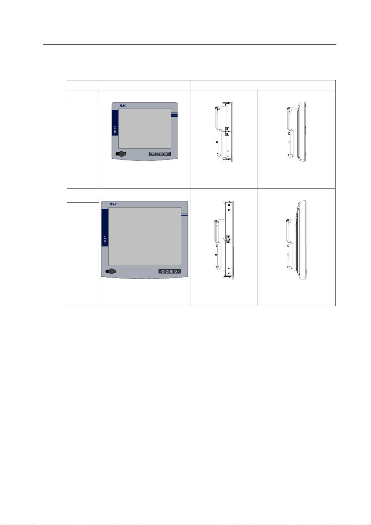
1.4 Overview
Device type Front panel Side view
TC12
TC17
a
b
c
Display: 12.1"
Dimensions: 315 mm x 280 mm
TC12-B [Built-In]
Built-in unit
Installation depth: 77 mm
Mounting with clamping jaws
TC17-B [Built-In]
TC12-S [Stand-Alone]
Add-on unit
Depth: 85 mm
Mounting at support arm system
TC17-S [Stand-Alone]
a
b
c
Display: 17.0"
Dimensions: 410 mm x 370 mm
Built-in unit
Installation depth: 84 mm
Mounting with clamping jaws
Add-on unit
Depth: 95 mm
Mounting at support arm system
Fig. 1-2: Overview
Rev. 1.00 dated 12.6.2006 Page 7 of 48
Page 12

Characteristics TM: TC - Hardware
This page is left intentionally blank!
Page 8 of 48 Rev. 1.00 dated 12.6.2006
Page 13

TM: TC - Hardware Installation
2 Installation
2.1 Unpacking and checking the delivery contents
Unpacking
• Check the packaging of the TC for transport damages.
• Remove the packaging carefully in order to avoid damages.
Save the original packaging for a possible new transportation of the TC.
Keep also the supplied documents.
Checking
• Check the contents of the packaging for visible transport damages.
• Check the contents for completeness by means of the delivery note.
2.2 Storing and transporting
The TC is constructed solidly indeed. The included components are however sensitive to
excessive shocks and impacts.
Therefore protect the TC against too great mechanical stress.
The device must be transported in its original packaging, completely with all shock-absorbing
parts.
2.3 Installing
Please adhere also to the chapter "Technical Data" during installing the TC.
Ensure that no condensation is formed on the device when it is stored/transported
during cold weather periods or when it is exposed to extreme deviations of
temperature.
The TC is approved for operation in closed rooms.
Rev. 1.00 dated 12.6.2006 Page 9 of 48
Page 14
Installation TM: TC - Hardware
You've got to observe the following items in order to effect a trouble-free operation
of the TC and to avoid damages.
2.3.1 Temperature
• Prior to commissioning:
- Allow the device time to adjust to room temperature.
- If condensation has formed, do not turn the device on until it is absolutely dry.
• Prevent overheating during operation:
Protect the device from direct radiation by sunlight or other heat sources.
• The ambient temperature during operation must not exceed +45 °C.
2.3.2 Ventilation
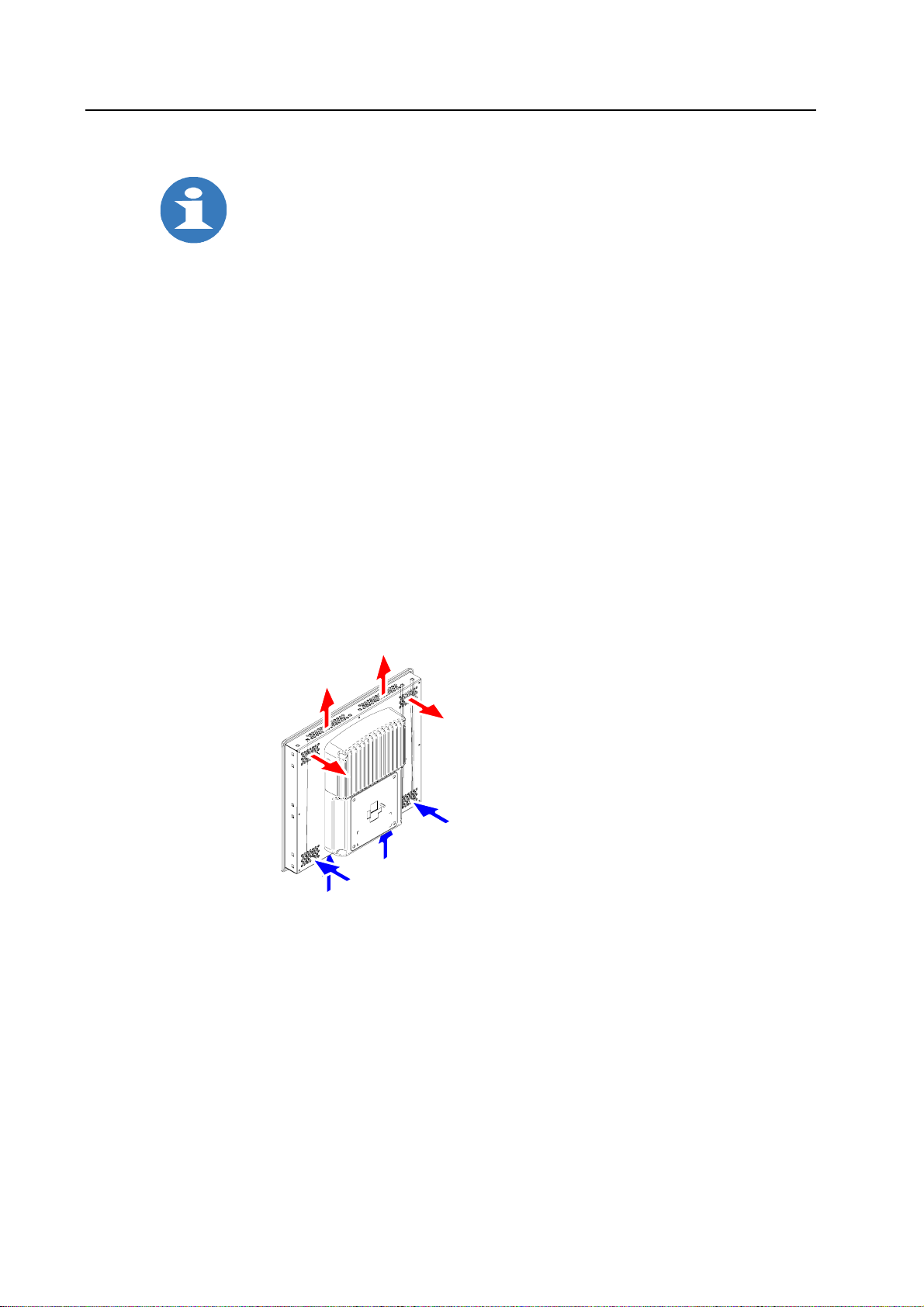
Built-in version:
• Do not cover ventilation holes by the installation:
They effect circulation of the air to cool the device.
• Provide sufficient volume for the air exchange in control cabinet/panel. The free space around
the TC must be at least 50 mm, at the rear side a free space of 20 mm is permissible.
Example: TC12-B
The following is valid correspondingly for other built-in versions.
Fig. 2-1: Ventilation
With closed housing, typical of the add-on version, take care of a suitable circulation.
Page 10 of 48 Rev. 1.00 dated 12.6.2006
Page 15
TM: TC - Hardware Installation
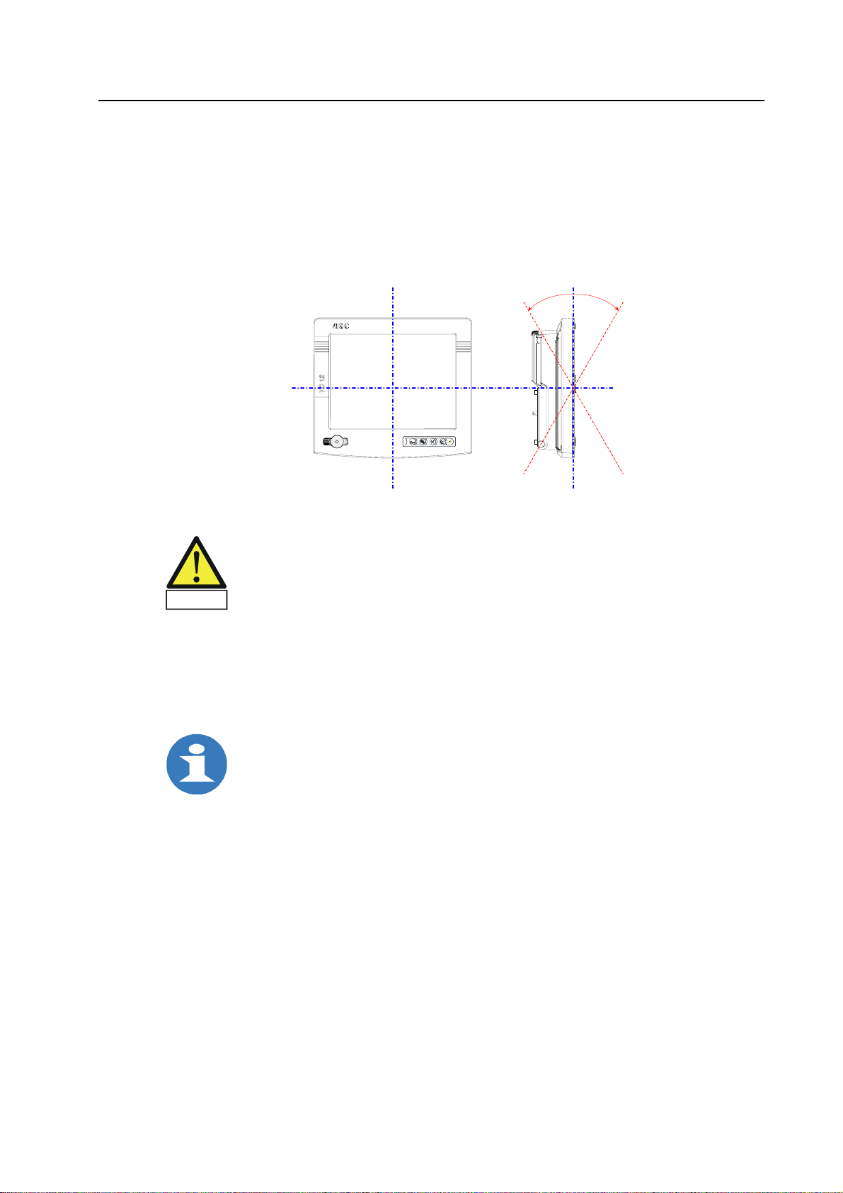
2.3.3 Installation position
The vertical installation as well as deviations up to ± 30° in the below indicated directions are
permitted.
For deviations from vertical installation it is to be considered that no accumulation of heat arises
in the interior of the housing.
Example: TC12-S [Stand-Alone]
The following is valid correspondingly for all versions.
+30° –30°
a
b
c
Fig. 2-2: Permissible installation positions
When the TC is installed in a position, which is not permissible,
any warranty will expire.
Warning
2.3.4 Installation cutout
Built-in version:
For dimensions of the installation cutout, see section "Fitting dimensions" of the respective
device in chapter "Mechanical Dimensions".
Also ensure free space to pull out the TC from the installation cutout.
Rev. 1.00 dated 12.6.2006 Page 11 of 48
Page 16
Installation TM: TC - Hardware
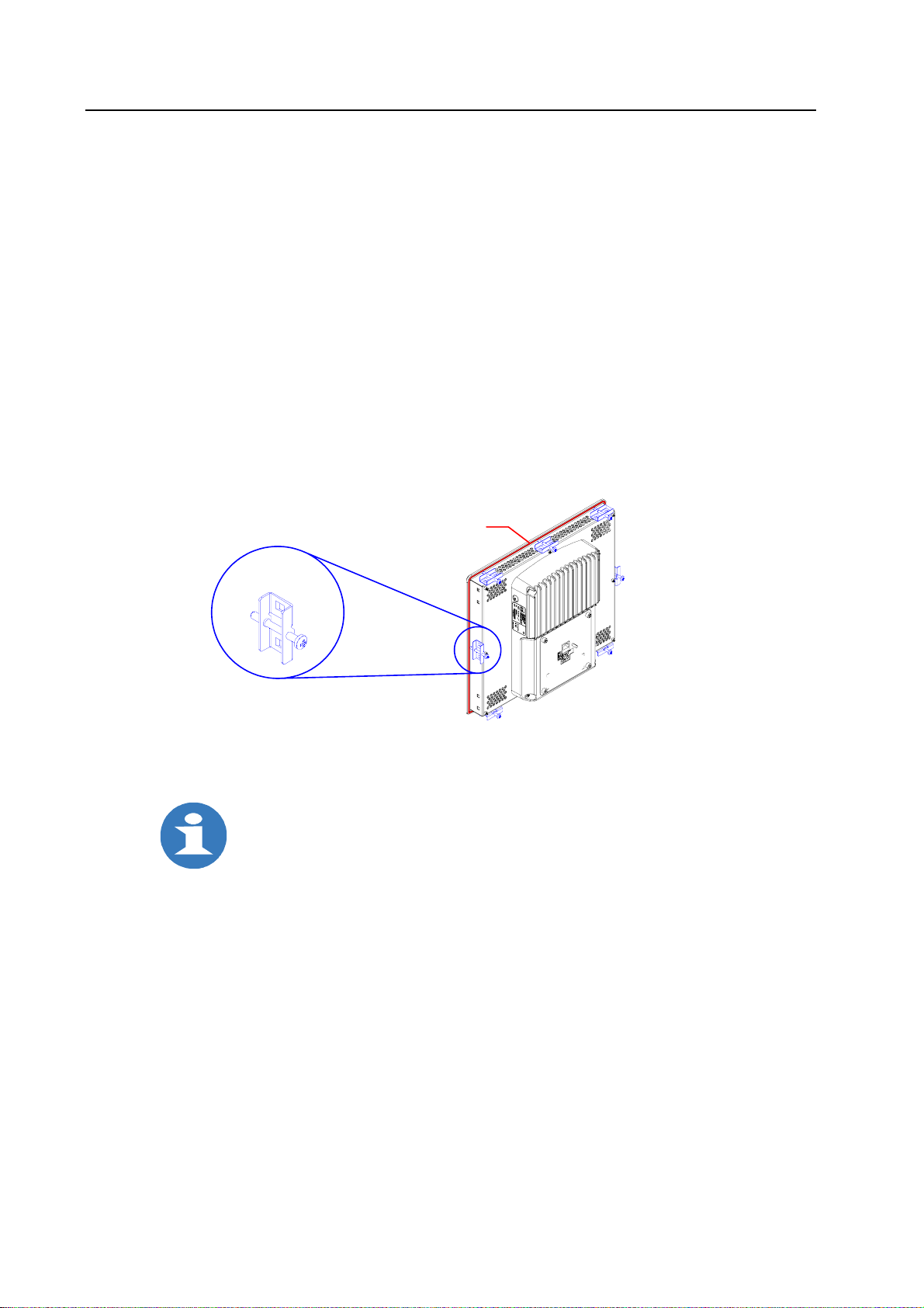
2.3.5 Mounting and sealing
Built-In = Built-in unit
TC as a built-in unit can be installed in cabinets and racks as well as
front panels of switching cabinets and desks.
• For mounting
There are clamping jaws to be set into the holes planned for this in the housing well.
- Put TC into the installation cutout from in front and hold it there.
- Place enclosed clamping jaws on the positions marked in the figure.
It is recommended: 3 x at the bottom, 3 x at the top, in the middle on the right and on the left.
- Fix the device in the installation cutout by tightening the Philips screws.
• For installation of the front panel according with IP 65
Sealing on the back side is not interrupted and goes round the border of the plate:
Round-cord of sponge rubber, Ø 3 mm, stuck in a groove with milling depth of 2 mm.
Example: TC12-B
The following is valid correspondingly for other built-in versions.
Sealing
Mounting
Rubber seal
Clamping jaw
Note:
Select the installation cutout so that the control cabinet/panel contains reinforcement
bars to stabilize the installation cutout. If necessary, install such reinforcement bars.
Protection class IP 65 is only guaranteed with sufficient rigidity of control cabinet/panel,
if the panel is installed correctly with the enclosed clamping jaws and the sealing is
positioned correctly.
Fig. 2-3: Mounting and sealing [Built-In]
Page 12 of 48 Rev. 1.00 dated 12.6.2006
Page 17
TM: TC - Hardware Installation
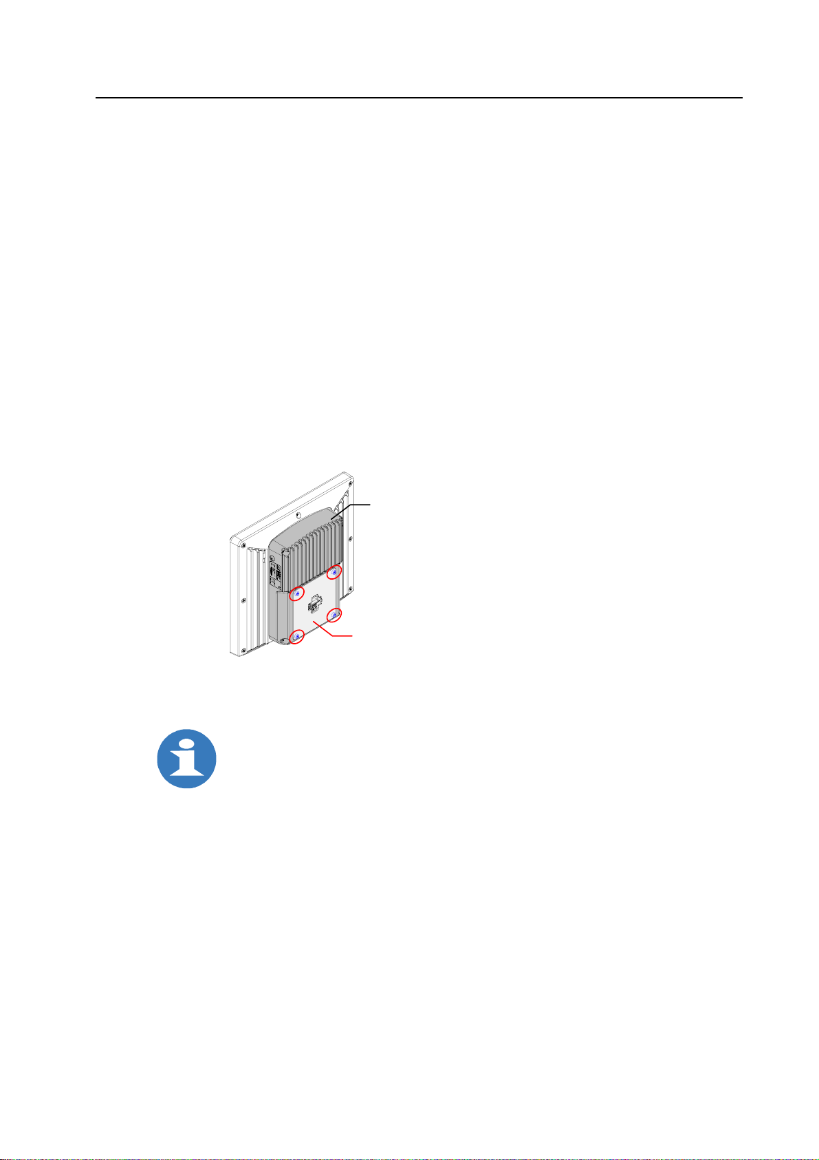
Stand-Alone = Add-on unit
TC as an add-on unit can be mounted at support arm systems of different manufacturers.
For mounting at a housing coupling (an equipment flange) the adapter plate on the rear of the
housing is removable.
The dimensions of the adapter plate and references for possible flange systems, you will find in
the section "Adapter plate" of the corresponding device in the chapter "Mechanical Dimensions".
An option is the delivery of the adapter plate with holes for fixing the corresponding flange
system.
• Loosen the four screws [M5x8, hexagon socket] of the adapter plate.
Remove the plate from the rear-mounted part of housing.
• When still not existing, drill holes into the adapter plate for the connection with the housing
coupling.
• Attach the housing coupling to the adapter plate.
• Screw on the adapter plate with mounted equipment flange on the rear-mounted part of housing.
Example: TC12-S
The following is valid correspondingly for other add-on versions.
Note:
Protection class IP 65 of the housing is only guaranteed, if the sealing on the
rear-mounted part of housing is not damaged during removal and fitting of the
adapter plate, and the sealing remains positioned correctly.
In addition it is to be ensured that the required tightness is obtained when mounting
the equipment flange at the adapter plate.
Rear-mounted part of housing
M5x8 screw
Hexagon socket (4x)
Adapter plate
Fig. 2-4: Mounting and sealing [Stand-Alone]
Rev. 1.00 dated 12.6.2006 Page 13 of 48
Page 18
Installation TM: TC - Hardware
2.4 Providing readiness of operation
Fail-safe connections for ensuring trouble-free operation:
Use only shielded cables and metallic connectors
for all signal connections.
Screw down or lock all plug connectors.
This improves the electrical shielding.
Do not install signal lines in the same cable ducts
as high voltage lines.
Caution
Before commissioning the system
all cable connections must be tested.
It has to be guaranteed that all voltages and signals
correspond to the required values.
Safe derivation of electric malfunctions:
Device and cabinet are to be connected on maximally short way
with a central grounding point.
Use a connection with maximally low impedance
between device and cabinet.
Caution
Carry out the grounding connection with green-yellow cable
with at least 2.5 mm² cross section.
Interference emission:
according to EN 61000-6-4
TC can cause interferences in the living area;
in this case it can be demanded from the operator to carry out adequate measures.
Especially for 230 V devices:
Notice:
Device must only be connected to a socket-outlet with grounding contact.
Danger
For complete disconnection from mains, the power plug must be unplugged.
Note:
Ensure that the socket-outlet with grounding contact of the internal installation is
freely accessible and is as close as possible to the device.
Caution
For installation in a cabinet, a central power disconnect switch must be provided.
The connector of the connection line to the supply voltage is a disconnecting appliance
according to EN 60950.
Pull the power plug before opening the device!
Danger
Especially for 24 V devices:
Notice:
Device may be operated only with safe extra low voltage
(extra low function potential with safe disconnection).
Warning
Page 14 of 48 Rev. 1.00 dated 12.6.2006
The power transformer must correspond to the valid specifications.
Page 19
TM: TC - Hardware Installation
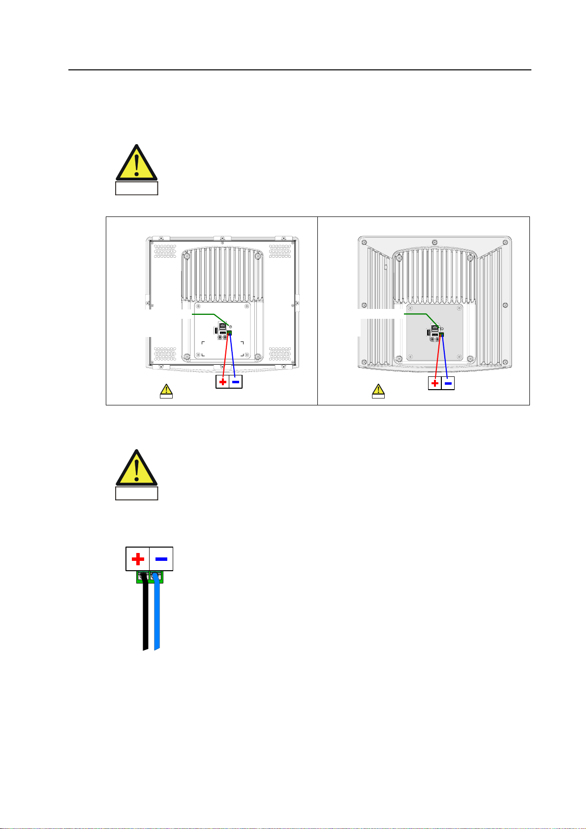
2.5 Connecting to power supply
Before connecting to mains
Does available voltage conform to the standard voltage requirement?
Functional grounding: Connect grounding point with cabinet ground!
Grounding bolt M4x10 at the interface sheet steel [Built-In] or flat pin 6.3x0.8 at the
Warning
View on rear of the housing
e.g. TC12-B [Built-In] e.g. TC12-S [Stand-Alone]
adapter plate [Stand-Alone] on the rear of the housing
Grounding point
Grounding bolt
M4x10
Voltage supply
24 VDC
Note:
pin assignment
Warning
Grounding point
Flat pin
6.3x0.8
Voltage supply
24 VDC
Note:
pin assignment
Warning
Fig. 2-5: Connecting to power supply
Mains supply voltage 24 VDC
24 VDC (18...36 VDC) supply for integrated DC/DC transducer.
The voltage applied must meet the requirements for a
safe extra low voltage (SELV) according to EN 60950!
Warning
Attend to "+" and "–" polarity!
Plug-in connection for 24 VDC
on the rear of the housing
+–
Plug component
FMC 1,5/2-ST-3,5
2 pin, pitch: 3.5 mm
Phoenix Contact
Fig. 2-6: Plug-in connection for 24 VDC
• Attach the supplied connector onto a 2-wire cable and plug it into the socket on the rear of the
housing. Consider "+" and "–" polarity.
• Connect the supply cable to a 24 V supply voltage that meets the requirements
for a safe extra low voltage (SELV) according to EN 60950.
The device is ready for 24 VDC operation.
Rev. 1.00 dated 12.6.2006 Page 15 of 48
Page 20

Installation TM: TC - Hardware
2.6 Using peripheral devices
The devices of MSC Tuttlingen GmbH offer by means of their peripheral interfaces the possibility
to connect different components.
When using standard peripheral devices (e.g. at the USB port) you have to note
that their electromagnetic interference immunity is often only sufficient for office
environments.
They are not suitable however for operating in the industrial environment!
Page 16 of 48 Rev. 1.00 dated 12.6.2006
Page 21
TM: TC - Hardware Commissioning and Operating
3 Commissioning and Operating
3.1 Expanding the TC
Note:
TC is a completely configured device.
An hardware expansion is not possible.
If necessary only the replacement of
Compact-Flash card and back-up battery is required.
3.1.1 General requirements
Limitation of liability
All technical specifications and approvals apply only to expansions approved by
MSC Tuttlingen GmbH.
No liability can be accepted for impairment of functions caused by the use of devices and
components from other manufacturers.
All modules and components are electrostatically sensitive.
The ESD notes are absolutely to be considered.
The opposite symbol indicates the use of electrostatically sensitive modules.
Precautions
Electronic components are extremely sensitive to electrostatic discharge.
Therefore, certain precautionary measures are necessary when handling these
modules. Please refer to the directive for Electrostatically Sensitive Devices
Caution
(ESD guideline).
• Before plugging in or unplugging any components, disconnect the TC from the power supply.
• Before plugging in the connection cables, the static charge of your body,
the TC and the cables must be brought to the same level.
To do this, briefly touch the metal housing.
• Discharge the electrostatic charge from tools you are using.
• Wear a grounding strip when handling components.
• Leave components in their packaging until they are to be installed.
• Components should only be held at the edges –
never touch connection pins and conductive tracks.
• Never operate the TC with the housing open.
Rev. 1.00 dated 12.6.2006 Page 17 of 48
Page 22
Commissioning and Operating TM: TC - Hardware
3.1.2 Opening the device and closing it again
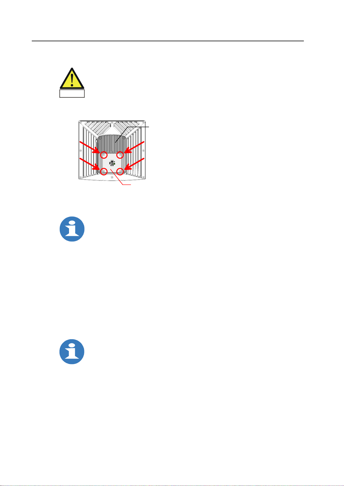
Notice:
Only remove the interface sheet steel [Built-In] or the adapter plate [Stand-Alone]
for exchanging Compact-Flash card and battery.
Caution
Example: TC17-S [Stand-Alone]
TC should remain closed. Do not loosen any further screws at the housing.
The following is valid correspondingly for all versions.
Rear-mounted part of housing
Adapter plate
Fig. 3-1: Opening the device and closing it again
Removing the interface sheet steel [Built-In] or the adapter plate [Stand-Alone]
Before opening:
Separate the device from supply.
Disconnect all connection cables from the TC.
• Loosen the four screws at the interface sheet steel [Built-In] or
at the adapter plate [Stand-Alone]:
M5x8 Hexagon socket
• Remove the interface sheet steel [Built-In] or the adapter plate [Stand-Alone]
to the back.
After having removed the interface sheet steel [Built-In] or the adapter plate [Stand-Alone],
battery and Compact-Flash card on the base board are accessible and can be exchanged
if necessary.
Mounting the interface sheet steel [Built-In] or the adapter plate [Stand-Alone]
While installing:
Pay attention to integrity and correct position of the sealing on the rear-mounted
part of housing. Protection class IP 65 all-around for Stand-Alone!
Guarantee contact between EMC spring clips and interface sheet steel [Built-In] or
adapter plate [Stand-Alone].
• Put in the interface sheet steel [Built-In] or the adapter plate [Stand-Alone] so across the
interface connections that the EMC spring clips at the USB sockets press against the interface
sheet steel [Built-In] or the adapter plate [Stand-Alone] from below and guarantee the contact
with that.
• Set the four screws through the holes in the interface sheet steel [Built-In] or
the adapter plate [Stand-Alone] into the threads in the rear-mounted part,
and tighten them again.
Page 18 of 48 Rev. 1.00 dated 12.6.2006
Page 23
TM: TC - Hardware Commissioning and Operating
3.1.3 Back-up battery
The battery that is installed on the base board provides Real Time Clock and CMOS memory
with a current, in order to permanently save system information, even if the board is separated
from the supply.
Type CR2032
Electrochemical system Primary Lithium cylindrical and button
Nominal capacity 230 mAh
Nominal voltage 3 V
Diameter 20 mm
Height 3.2 mm
Weight 3 g
Replacing the battery
When the charge is too low or the battery is empty, the data stored in the CMOS RAM
(e.g. date and time) might not be accurate.
Then the Lithium battery must be replaced.
To replace the battery, follow these steps:
• Observe the precautions in section "General requirements".
• Open the housing as described in section "Opening the device and closing it again".
• With a medium flat-bladed screwdriver, gently pry the battery enough
to free the battery from its socket.
• Install the new battery in the socket, orienting the "+" face-up.
• Close the TC again.
Notice:
Incorrect replacement leads to danger of explosion.
The battery may be replaced only with an identical battery or with a type
recommended by the manufacturer.
Caution
Ensure that you insert the battery in the right way (see polarity).
Note:
Do not throw Lithium batteries into the household waste. They must be disposed of
in accordance with local regulations concerning special waste.
Rev. 1.00 dated 12.6.2006 Page 19 of 48
Page 24

Commissioning and Operating TM: TC - Hardware
3.1.4 Flash memory
The base board of the TC is firmly equipped with a Compact-Flash card.
The Compact-Flash card is used as a storage medium exclusively for system information.
Notice:
Do not "save" any data to the storage medium if a supply voltage failure occurs!
The variable voltage in such an event causes uncontrolled writing to the storage
medium, data files may be overwritten or deleted.
UPS (Uninterruptible Power Supply) prevents loss of data!
Exchanging the Compact-Flash card
If data are destroyed on the Compact-Flash card, it is to be replaced by a new one,
that can be got by MSC Tuttlingen GmbH.
To replace the Compact-Flash card, follow these steps:
• Observe the precautions in section "General requirements".
• Open the housing as described in section "Opening the device and closing it again".
• Remove the damaged Compact-Flash card and insert the new card.
• Close the TC again.
Page 20 of 48 Rev. 1.00 dated 12.6.2006
Page 25
TM: TC - Hardware Commissioning and Operating
3.2 Connecting peripheral devices
3.2.1 Interfaces
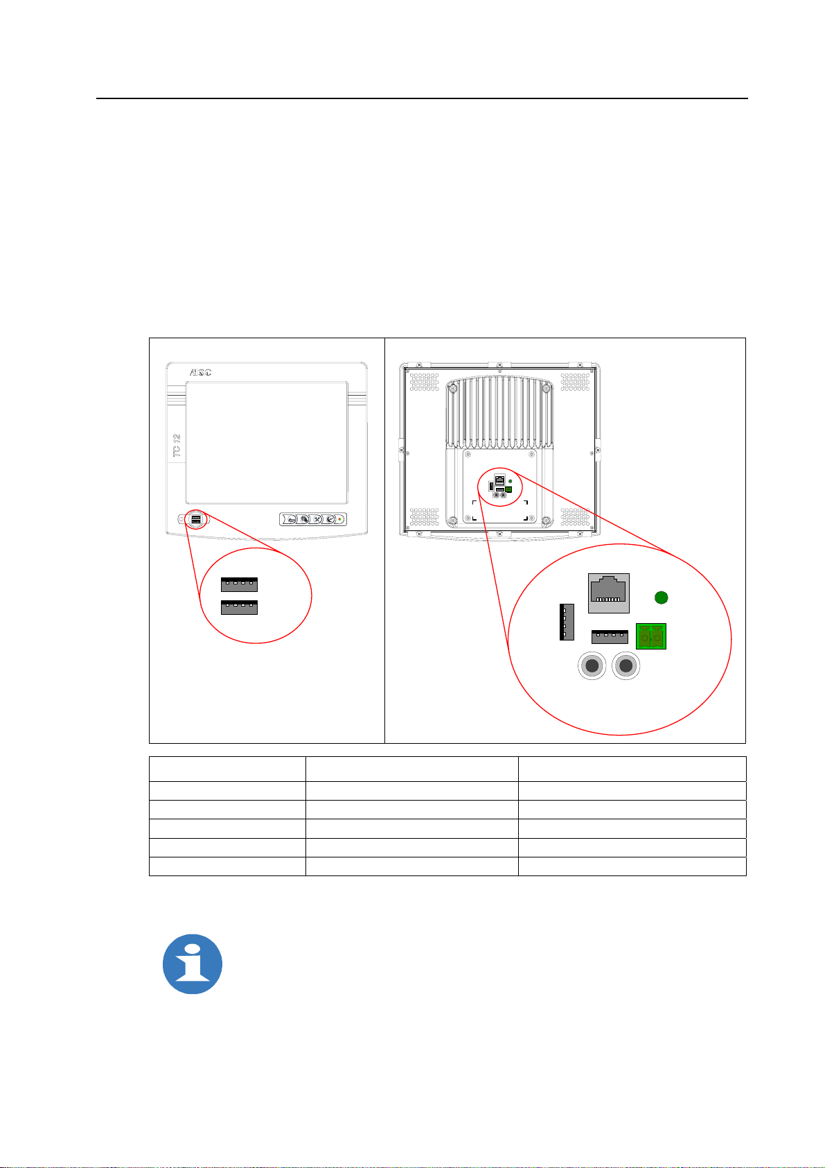
Access to ports
Connections to peripheral devices are placed on the front under the covering and on the rear of
the housing.
Example: TC12-B [Built-In]
The following is valid correspondingly for all versions.
Front view Rear view
a
b
c
Ethernet
USB
Grounding
–
+
24 VDC
Audio Line-Out
(Stereo)
USB
USB
Interface Connector type Annotation
USB port USB Type A, 4 pin 2 x on the front, under the covering
USB port USB Type A, 4 pin 2 x on the rear
Ethernet RJ-45 socket, 8 pin on the rear
MIC-Input (Mono) Socket for switchboard plug 3.5 mm on the rear
Audio Line-Out (Stereo) Socket for switchboard plug 3.5 mm on the rear
B
S
U
MIC-Input
(Mono)
Fig. 3-2: Connections to periphery
Notice:
During operation: Do not connect or disconnect any plugs!
When connecting peripheral devices, pay attention to their industrial compatibility!
Configuration of the connections, see identification label!
Terminals are standardized contacts with known default assignments.
Rev. 1.00 dated 12.6.2006 Page 21 of 48
Page 26
Commissioning and Operating TM: TC - Hardware
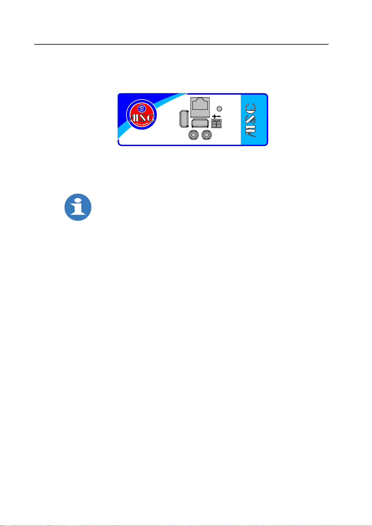
Identification label
The identification label outside on the interface sheet steel [Built-In] or inside on the adapter plate
[Stand-Alone] shows the configuration of the interfaces.
e
d
.
n
e
g
n
i
l
t
t
u
t
c
s
m
.
w
w
w
MIC-Input
(Mono)
B
S
U
Ethernet
USB
Audio
Line-Out
(Stereo)
Erdung
Power
24V
Fig. 3-3: Identification label
3.2.2 Peripherals
Notice:
For the process operation external keyboard and external mouse
must be provided with the CE mark (for industrial environment!).
External keyboard and touchscreen may be operated in parallel.
Keyboard
The TC is designed to connect a USB keyboard.
It can be connected to one of the USB ports.
Mouse
The TC is designed to connect a USB mouse.
It can be connected to one of the USB ports.
Data medium
The connection of a data medium as for example USB stick and drive unit with USB port
is possible at one of the USB ports.
Ethernet network
The TC can be connected to a computer network via the RJ-45 socket "Ethernet".
Ethernet is a standard for local networks. Twisted-pair cables are used for networking the
computers.
Page 22 of 48 Rev. 1.00 dated 12.6.2006
Page 27
TM: TC - Hardware Commissioning and Operating
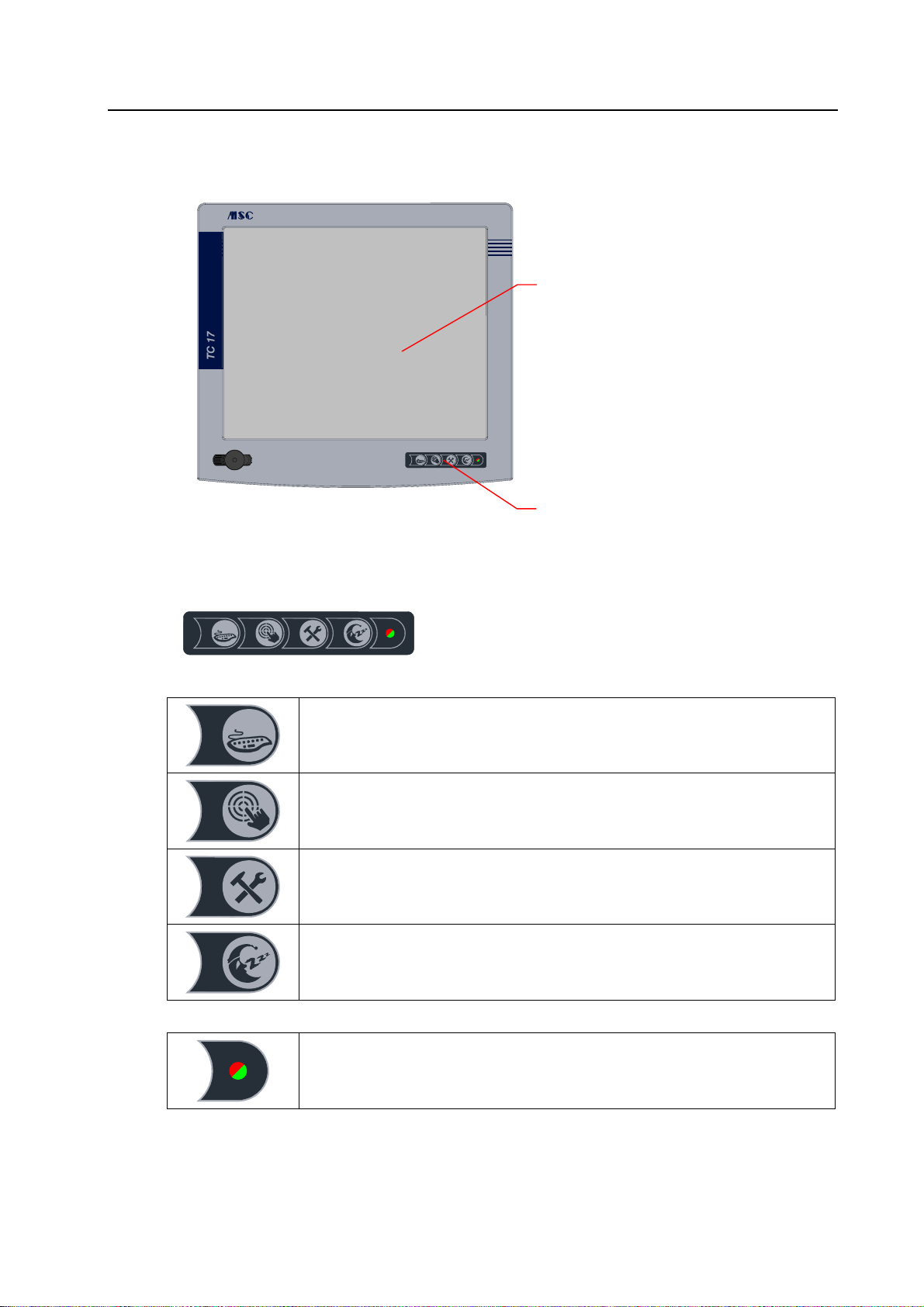
3.3 Operating the TC
Touchscreen
a
b
c
3.3.1 Membrane keyboard
a
b
c
Function keys
a
b
c
Soft keyboard
Touch calibration
Tools
- Configuring the device parameters.
- Operating the user software.
Stand by
Pressing for more than 2 seconds causes a hardware reset.
Membrane keyboard
The membrane keyboard on the front panel contains four function keys
and the status LED.
Fig. 3-4: Front view [e.g. TC17-S]
Fig. 3-5: Membrane keyboard
Status LED
red flashing = failure
green = indication of operation
alternately red-green flashing: "Stand by" mode (display out)
Rev. 1.00 dated 12.6.2006 Page 23 of 48
Page 28
Commissioning and Operating TM: TC - Hardware
3.3.2 Touchscreen
The touchscreen is integrated in the display section of the front panel.
By touching the sensitive screen according to the represented functions on the display,
you operate the computer, for example through pressure on an indicated field.
Notice:
Do not use any metallic or peaked objects –
these could damage the touch surface.
3.4 Setting/Operating the TC
3.4.1 Operating system and software
According to your order MSC Tuttlingen GmbH configures the TC as Win Client, Web Client or
extended Client, equipped with operating system and software based on that.
Description for handling of the operating interface
Successively instructions will be written according to these software packages.
These ones include the use of the corresponding software and complete the
submitted description of device.
3.4.2 Cleaning
Switch off the TC and all devices connected to it, before starting the cleaning.
Notice:
1)
Prerequisite for a proper maintenance of the device
is that the device1)
is cleaned regularly according to the following guidelines.
1)
"Device" means for the different versions:
"Device" Device version Protection class
Front Built-In [Built-in unit] IP 65 at front, IP 20 at rear
Total device Stand-Alone [Add-on unit] IP 65 all-around
• It is allowed to use only pure water, if necessary with small additions of neutral detergents
(pH 5-8). Where appropriate with the aid of smooth, not abrasive cloths, rags or industrial
cotton wool. Violent rubbing is to be avoided.
• The removal of greasy, oily or sooty substances can be done with aromatic-free terpentine
substitute or isopropyl alcohol (IPA). Remains of adhesives, silicone rubber or adhesive tapes
etc. can be removed also in this way.
• It must not be used any solvents that contain esters, ketones, alcohols, aromatics, glycolic
ether or halogenated hydrocarbons or the like.
• Avoid scraping and abrasive agents.
• Do not use any strongly acid or alkaline cleaning and wetting agents.
• Never use detergents of unknown composition.
• The detergents may have a maximum of 25 °C. Steam jet devices must not be applied.
• Immediately after every cleaning process, it is to be rinsed with pure cold water.
Page 24 of 48 Rev. 1.00 dated 12.6.2006
Page 29

TM: TC - Hardware Commissioning and Operating
3.5 Terms of warranty
For the devices of MSC Tuttlingen GmbH, the agreements determined in the General Terms and
Conditions (AGB) are valid.
All wearing parts are excluded from warranty.
Wearing parts are parts which are subject to maintenance or routine check-up:
all fans, all drive units, display backlight, battery.
Rev. 1.00 dated 12.6.2006 Page 25 of 48
Page 30

Commissioning and Operating TM: TC - Hardware
This page is left intentionally blank!
Page 26 of 48 Rev. 1.00 dated 12.6.2006
Page 31
TM: TC - Hardware Technical Data
)
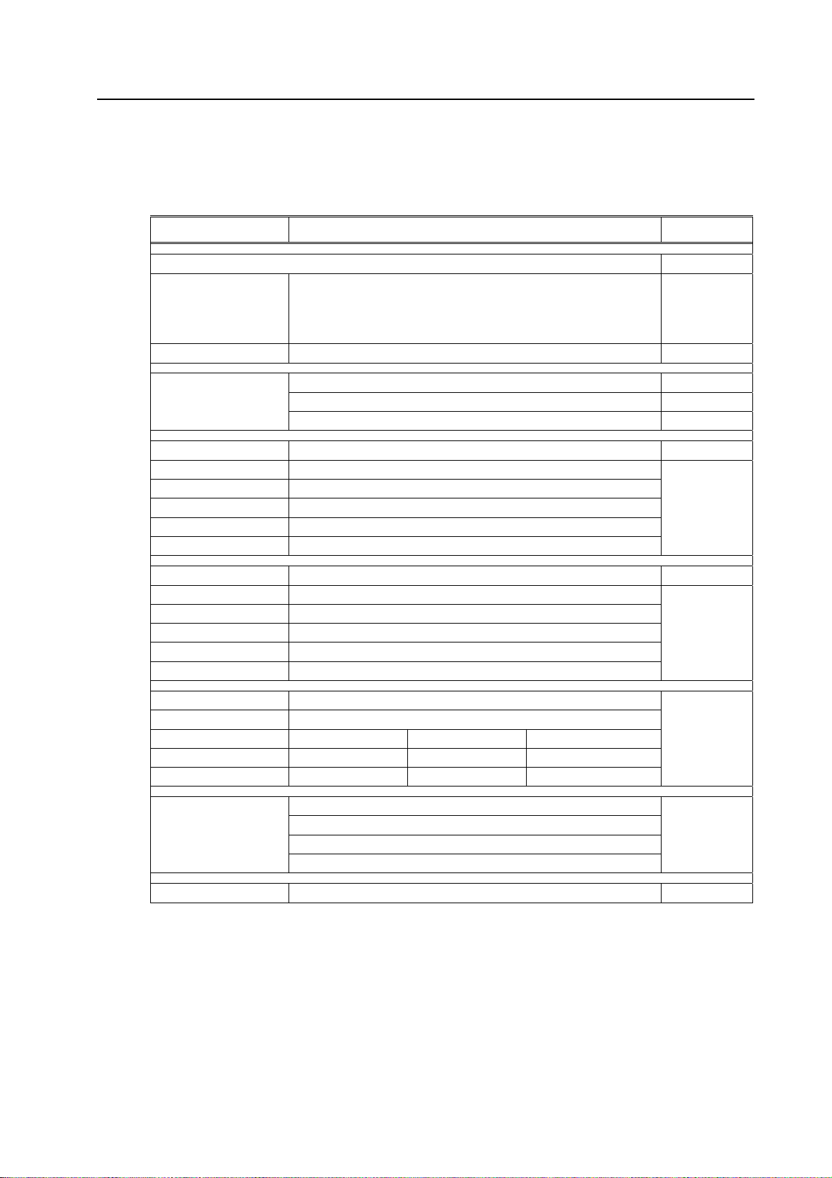
4 Technical Data
4.1 General
Component Description Indication
Basic system
Front Aluminum
Operating panel Touchscreen resistive-analogue
Display
Active matrix LCD
TFT color
Built-In
Protection class IP 65 at front, IP 20 at rear
Cooling Fanless: no CPU fan, no device fan
Housing well Galvanized sheet steel (thickness 1 mm)
Rear-mounted part Aluminum
Mounting Clamping jaws for fixing in the installation cutout
Stand-Alone
Protection class IP 65 all-around
Cooling Fanless: no CPU fan, no device fan
Housing well Aluminum
Rear-mounted part Aluminum
Mounting Flange mounting for support arm or pedestal
Base board
CPU on ET(e) module x86 400 MHz
... Win Client ... Web Client ... extended Client
Memory extension 128 MB SDRAM 256 MB SDRAM application-specific
Compact-Flash 128 MB CF card 256 MB CF card application-specific
External interfaces
Option
TC
printed in MSC design / silk-screen printing in RAL 5013 (cobalt blue)
customer-specific design is possible
membrane keyboard with 4 function keys
Status LED
12.1" / SVGA (800 x 600 pixel) 12
17.0" / SXGA (1280 x 1024 pixel) 17
Built-in unit -B
Add-on unit -B
Board for integration of CPU module at ETX form factor
2 x USB 1.11) at front, covering IP 65
2 x USB 1.11) at rear
1 x Ethernet 10/100 Base-T
MIC-Input (Mono) / Audio Line-Out (Stereo)
WLAN antenna with adapter /WLAN
Note:
1
There are only 3 x USB with maximum current consumption.
Rev. 1.00 dated 12.6.2006 Page 27 of 48
Page 32
Technical Data TM: TC - Hardware
Component Description Indication
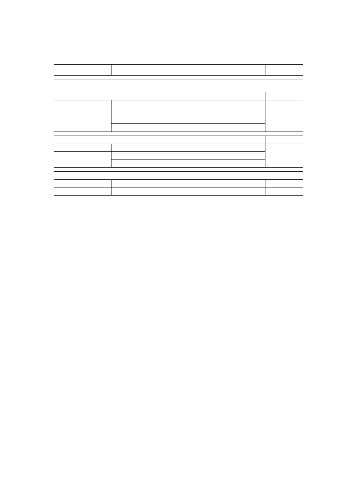
Configuration as …
Win Client
/Win
Operating system Windows CE 5.0
Software Microsoft Terminal Client (RDP)
.NET Web Services
CITRIX Client ICA
Web Client
/Web
Operating system Embedded Linux
Software Browser Mozilla
Java VM2 (JDK 1.4x)
extended Client
Operating system Windows CE 5.0
Software zenOn /Zenon
Page 28 of 48 Rev. 1.00 dated 12.6.2006
Page 33

TM: TC - Hardware Technical Data
)
Supply voltage
Power consumption
24 VDC / 18...36 VDC (SELV)
Device with 12.1" display 40 W typ.
Device with 17.0" display 70 W typ.
Mechanical dimensions
depending on device variation
(see chapter "Mechanical Dimensions")
Weight
depending on equipment
(see section "Device-specific" in this chapter)
Ambient temperature
Opera t i o n ( v e r t i c a l i n s t a l l a t i o n , with natural convection)
Device with 12.1" display, basic configuration 0 ºC to +50 ºC
Device with 17.0" display 0 ºC to +45 ºC
Storage -20 ºC to +60 ºC
Relative humidity
50% max. at +40 ºC non condensing
90% max. at +20 ºC non condensing
Ambient air
Oscillation load (in operation)
free of corrosive gases
according to EN 60068-2-6
10 Hz to 58 Hz 3.0 mm
58 Hz to 150 Hz 2 g
Shock load (in operation)
according to EN 60068-2-27
15 g, 11 ms, 3 shocks
EMC directive 89/336/EEC
Testing for EEC conformity
Interference emission according to EN 61000-6-4
Interference resistance according to EN 61000-6-2
Test certificate
CE
1)
Notice:
1
24 volt devices correspond to protection class II in accordance with EN 60950.
The voltage applied must meet the requirements for a safe extra low voltage (SELV)
according to EN 60950.
Rev. 1.00 dated 12.6.2006 Page 29 of 48
Page 34

Technical Data TM: TC - Hardware
4.2 Device-specific
Specific dates for different versions of the TC line are described in this section.
Type indication Article no. Front Display Touch Housing Other* Weight
315x280 front panel
410x370 front panel
12.1" TFT color, SVGA
17.0" TFT color, SXGA
TC12-B/Win 63 09 U22 x x x x x 4.15
TC12-B/* x x x x
TC12-S/Win 63 09 U21 x x x x x 4.95
TC12-S/* x x x x
TC17-B/Win 63 09 U42 x x x x x 6.75
TC17-B/* x x x x
TC17-S/Win 63 09 U41 x x x x x 7.95
TC17-S/* x x x x
* Further specifications to type indication you can find in the section "Nomenclature"
of chapter "Characteristics" and "General" of chapter "Technical Data".
12.1" resistive-analogue
17.0" resistive-analogue
Galvanized sheet steel
Aluminum
/Win
/Web
/Zenon
/Citrix
/WLAN Weight (standard) [kg],
approx.
The accessories (clamping jaws) for the built-in version weigh 100 g.
Page 30 of 48 Rev. 1.00 dated 12.6.2006
Page 35
TM: TC - Hardware Technical Data
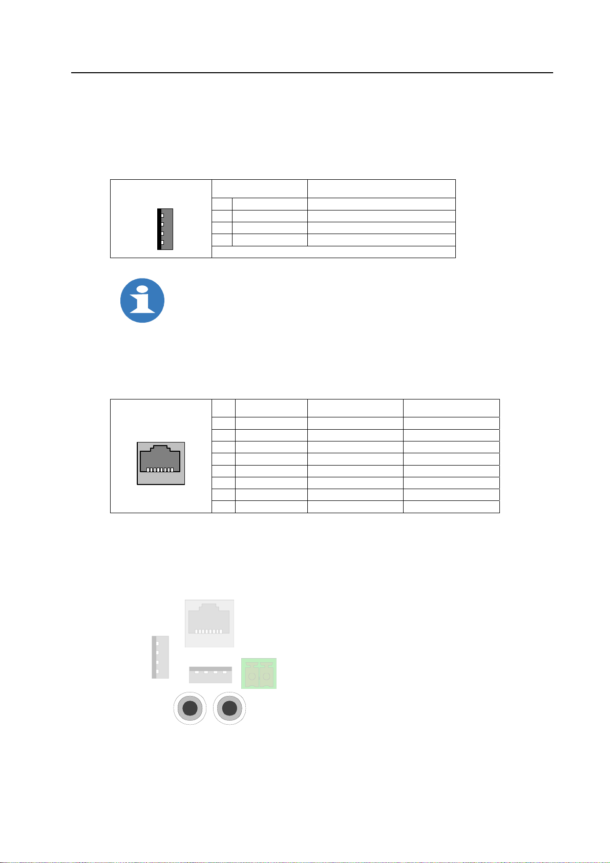
4.3 External connections
4.3.1 USB ports
4 pin USB connector, Type A,
to connect USB peripheral devices.
USB Type A,
4 pin
4
3
2
1
USB Meaning
1 VCC USB Voltage supply
2 USB– Data
3 USB+ Data
4 GND Ground
Note:
2 x USB 1.1 at front, covering IP 65
2 x USB 1.1 at rear
There are only 3 x USB with maximum current consumption.
4.3.2 Ethernet connection
One Ethernet connection via 10Base-T connector "Ethernet".
The Ethernet controller supports transfer rates of 10 Mbit/s and 100 Mbit/s.
10Base-T
RJ-45 CAT5
18
Pin Signal Meaning Input/Output
1 TxD+ 10Base-T Transmit Differential Output
2 TxD– 10Base-T Transmit Differential Output
3 RxD+ 10Base-T Receive Differential Input
4 N.C. not connected --5 N.C. not connected --6 RxD– 10Base-T Receive Differential Input
7 N.C. not connected --8 N.C. not connected ---
4.3.3 Microphone input and audio output
Fig. 4-1: USB
Fig. 4-2: Ethernet
Two sockets for switchboard plug, each 3.5 mm, for microphone input (mono) and
audio output (stereo).
MIC-Input
(Mono)
Audio Line -Out
(Stereo)
Fig. 4-3: Microphone input and audio output
Rev. 1.00 dated 12.6.2006 Page 31 of 48
Page 36

Technical Data TM: TC - Hardware
This page is left intentionally blank!
Page 32 of 48 Rev. 1.00 dated 12.6.2006
Page 37
TM: TC - Hardware Mechanical Dimensions
5 Mechanical Dimensions
5.1 TC12-B
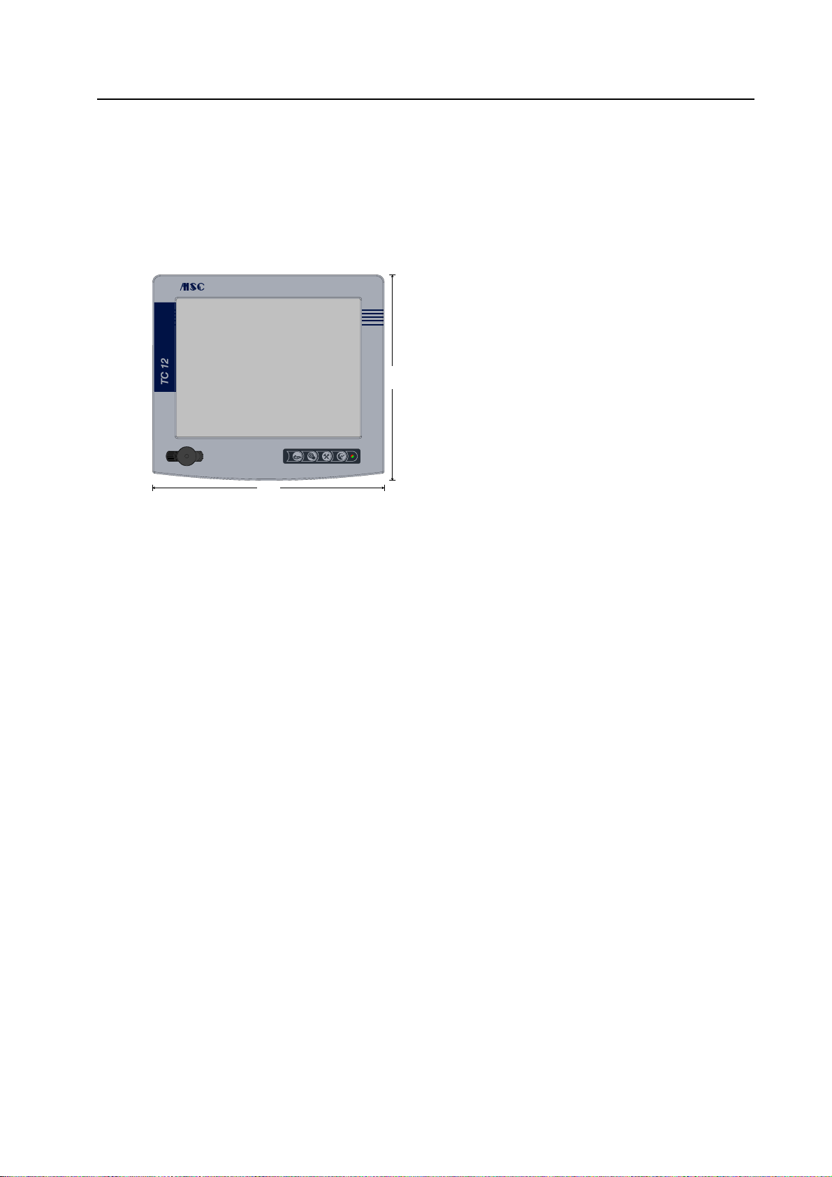
5.1.1 Front
• TC12-B
Built-In = Built-in unit
• 315 mm x 280 mm
250 x 188.5
a
b
c
0
8
2
• 12.1" display
• Membrane keyboard
- 4 function keys
- LED
• 2 x USB under covering
315
• Touchscreen
Fig. 5-1: TC12-B [Built-In] – Front
Rev. 1.00 dated 12.6.2006 Page 33 of 48
Page 38
Mechanical Dimensions TM: TC - Hardware
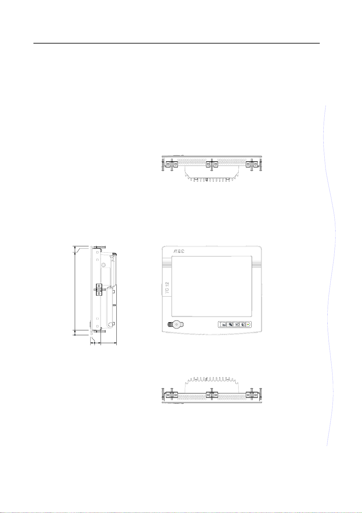
5.1.2 Device dimensions
TC12-B [Built-In]
280
272.5
15.5
a
b
c
0
5
0
7
-
7
2
7
Page 34 of 48 Rev. 1.00 dated 12.6.2006
Page 39
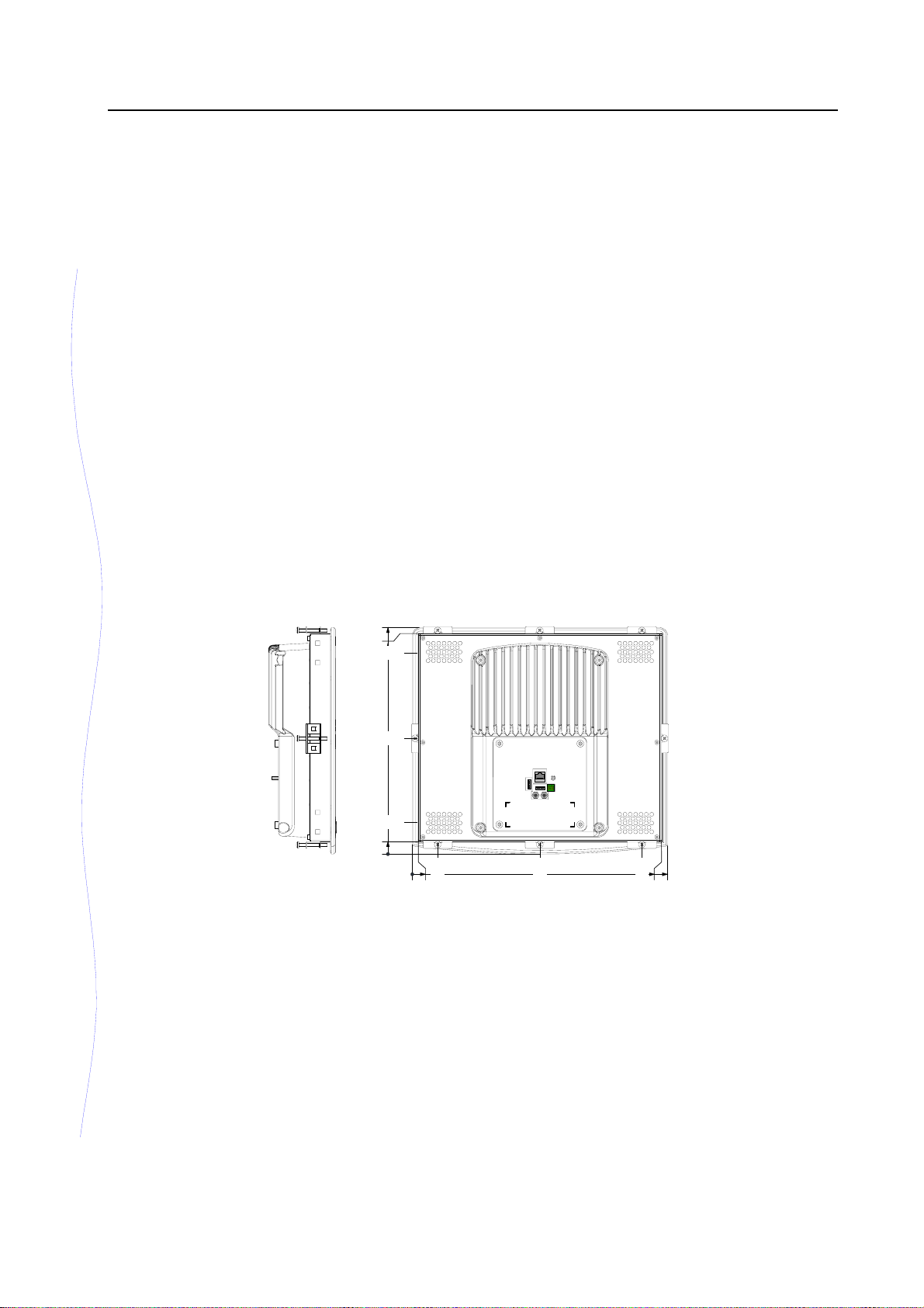
TM: TC - Hardware Mechanical Dimensions
TC12-B [Built-In]
280
272.5
248.5
143
15.5
39.5
0
5
.
1
3
0
5
.
7
5
.
7
5
1
5
.
3
8
5
5
2
.
1
7
3
0
3
General tolerances
ISO 2768 – mK
Fig. 5-2: TC12-B [Built-In] – Device dimensions
Note: Positioning the clamping jaws
It is recommended to place the enclosed clamping jaws at the positions marked in
the figure to fix the device.
Rev. 1.00 dated 12.6.2006 Page 35 of 48
Page 40

Mechanical Dimensions TM: TC - Hardware
5.1.3 Fitting dimensions
TC12-B [Built-In]
Recommended installation cutout
302
9
5
2
Fig. 5-3: TC12-B [Built-In] – Fitting dimensions
Page 36 of 48 Rev. 1.00 dated 12.6.2006
Page 41
TM: TC - Hardware Mechanical Dimensions
5.2 TC12-S
5.2.1 Front
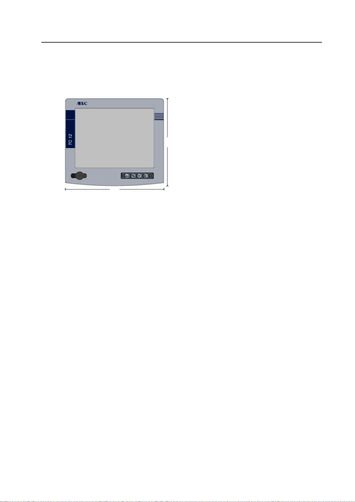
• TC12-S
Stand-Alone = Add-on unit
• 315 mm x 280 mm
0
8
2
• 12.1" display
• Membrane keyboard
- 4 function keys
250 x 188.5
a
b
c
- LED
• 2 x USB under covering
315
• Touchscreen
Fig. 5-4: TC12-S [Stand-Alone] – Front
Rev. 1.00 dated 12.6.2006 Page 37 of 48
Page 42
Mechanical Dimensions TM: TC - Hardware
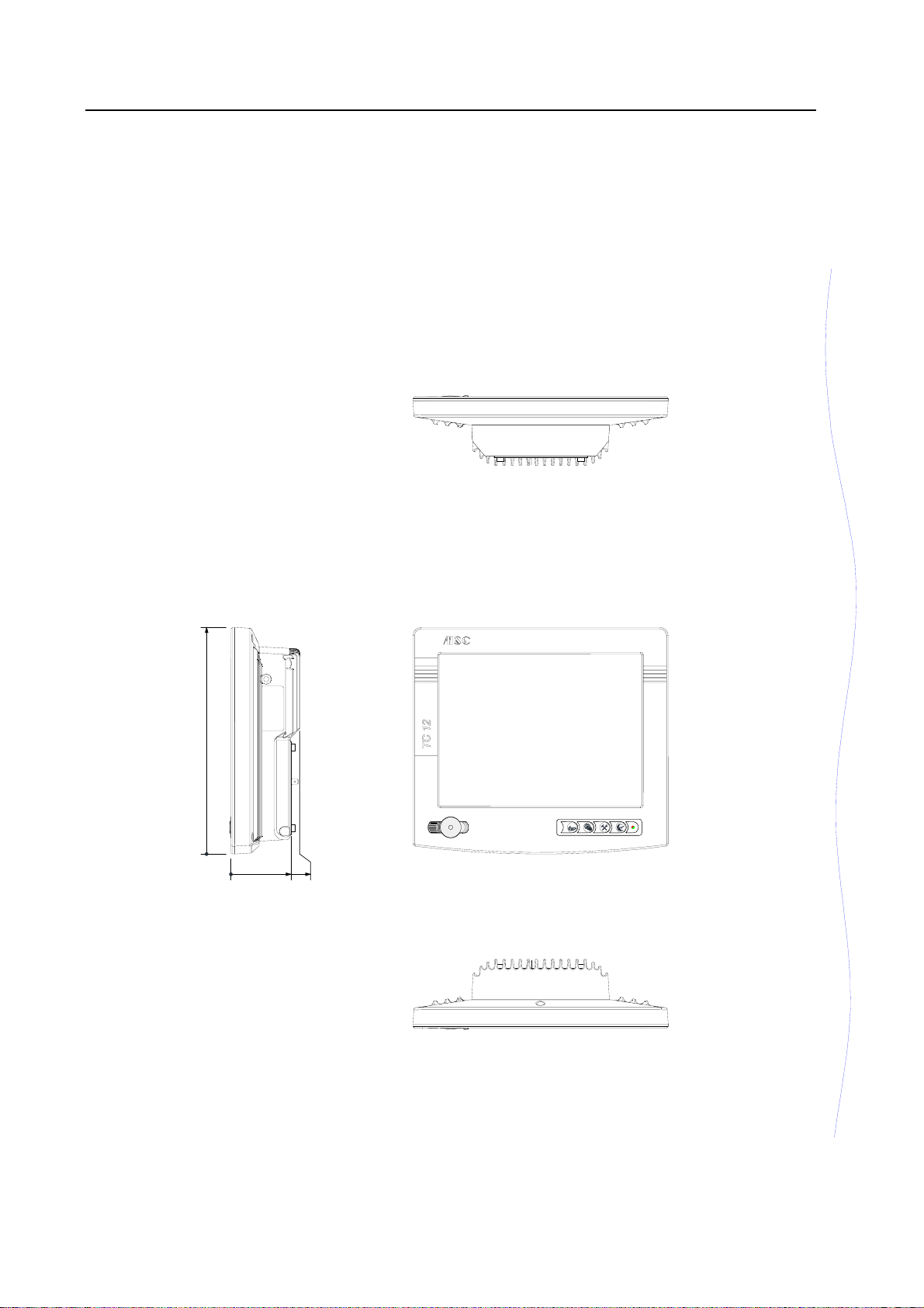
5.2.2 Device dimensions
TC12-S [Stand-Alone]
280
a
b
c
0
0
5
3
.
8
4
7
Page 38 of 48 Rev. 1.00 dated 12.6.2006
Page 43
TM: TC - Hardware Mechanical Dimensions
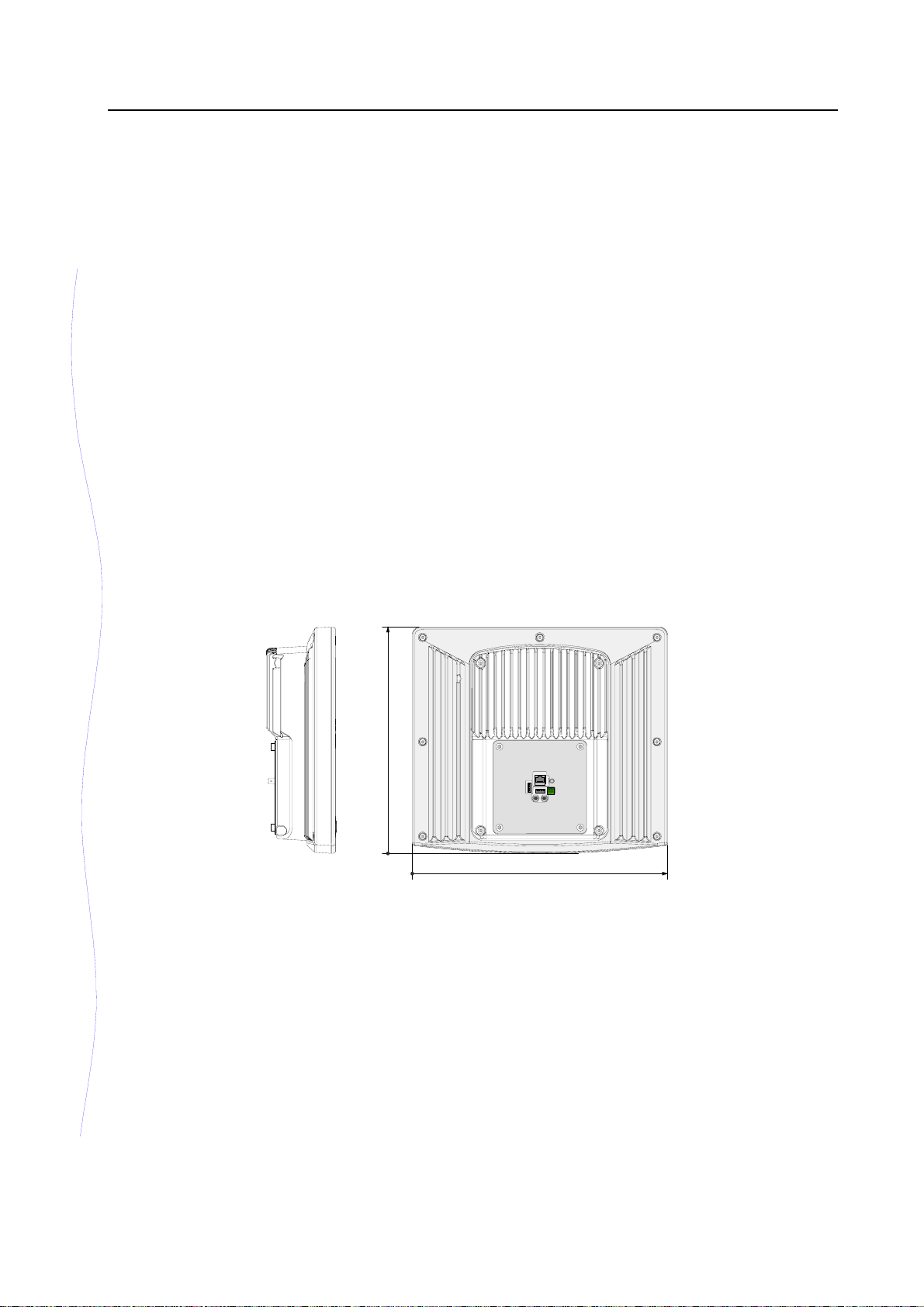
TC12-S [Stand-Alone]
280
0
0
5
1
3
General tolerances
ISO 2768 – mK
Fig. 5-5: TC12-S [Stand-Alone] – Device dimensions
Rev. 1.00 dated 12.6.2006 Page 39 of 48
Page 44
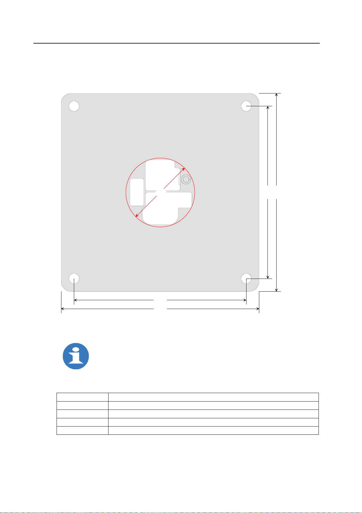
Mechanical Dimensions TM: TC - Hardware
5.2.3 Adapter plate
TC12-S [Stand-Alone]
for mounting a housing coupling
0
0
4
5
0
1
1
1
100
115
Material thickness: 2.5 mm
Fig. 5-6: TC12-S [Stand-Alone] – Adapter plate
Note:
When selecting a housing coupling (an equipment flange) it is to be ensured
that the tube internal diameter is at least 40 mm.
Upon request the adapter plate is provided with holes to mount the particular
flange system.
Possible standard flange systems
Manufacturer Indication
Rittal CP, CP-S (stainless steel), CP-S (angle coupling), CP-L (device coupling)
Bernstein CS-480 NR, CS-200 (SL), CS-600 NR (stainless steel)
ROSE GT48/2 (flange angle coupling), GT50/2, GT60/2, GTH48, GTH60
HASEKE KSE 60 (angle)coupling
Scale 1:1
Page 40 of 48 Rev. 1.00 dated 12.6.2006
Page 45
TM: TC - Hardware Mechanical Dimensions
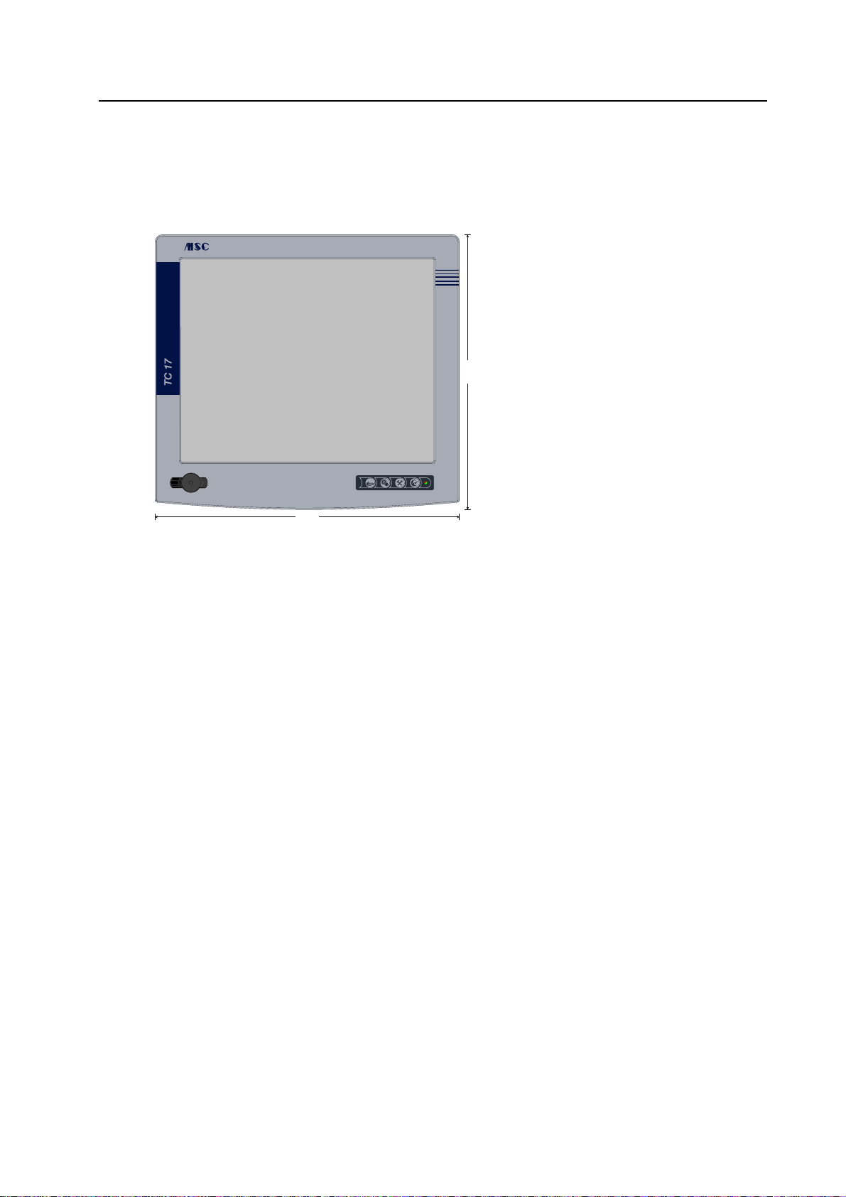
5.3 TC17-B
5.3.1 Front
• TC17-B
Built-In = Built-in unit
• 410 mm x 370 mm
• 17.0" display
0
7
3
• Membrane keyboard
- 4 function keys
- LED
• 2 x USB under covering
341 x 273.5
a
b
c
• Touchscreen
410
Fig. 5-7: TC17-B [Built-In] – Front
Rev. 1.00 dated 12.6.2006 Page 41 of 48
Page 46
Mechanical Dimensions TM: TC - Hardware
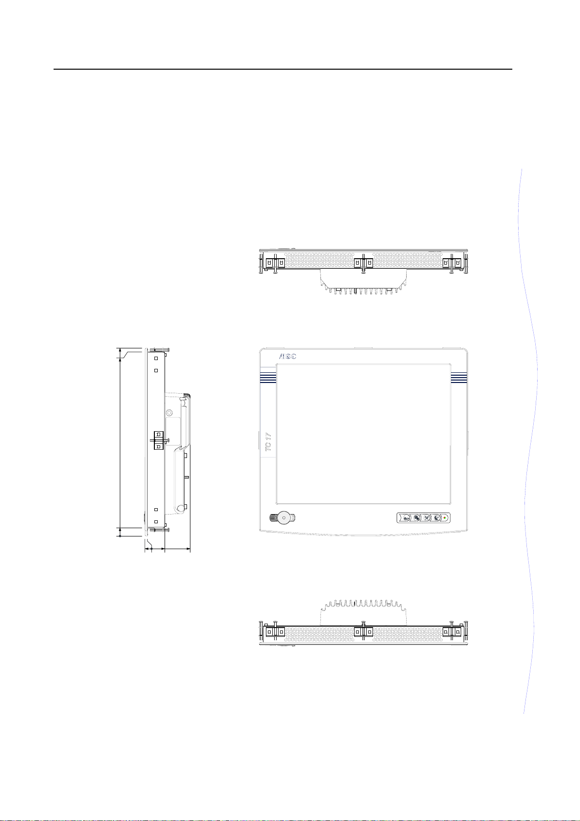
5.3.2 Device dimensions
TC17-B [Built-In]
370
362.5
16.5
a
b
c
0
5
0
-
4
4
8
3
Page 42 of 48 Rev. 1.00 dated 12.6.2006
Page 47
TM: TC - Hardware Mechanical Dimensions
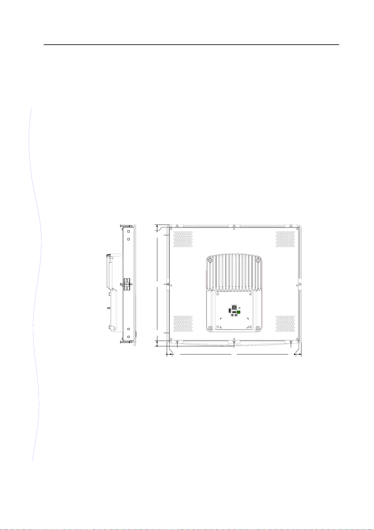
TC17-B [Built-In]
370
362.5
338.5
188.5
16.5
40.5
0
5
.
1
3
0
5
.
7
5
0
2
5
.
8
7
5
3
.
2
0
4
General tolerances
ISO 2768 – mK
Fig. 5-8: TC17-B [Built-In] – Device dimensions
0
1
4
Note: Positioning the clamping jaws
It is recommended to place the enclosed clamping jaws at the positions marked in
the figure to fix the device.
Rev. 1.00 dated 12.6.2006 Page 43 of 48
Page 48
Mechanical Dimensions TM: TC - Hardware
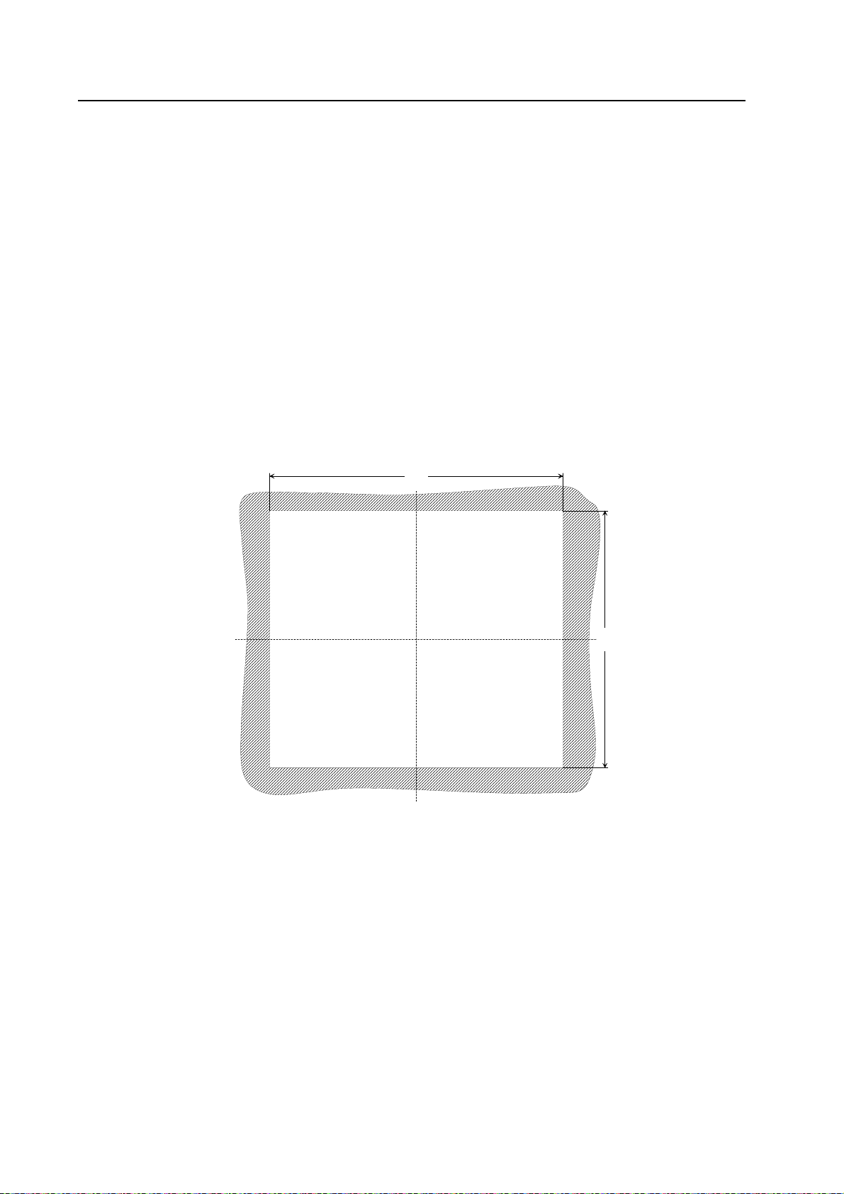
5.3.3 Fitting dimensions
TC17-B [Built-In]
Recommended installation cutout
397
8
4
3
Fig. 5-9: TC17-B [Built-In] – Fitting dimensions
Page 44 of 48 Rev. 1.00 dated 12.6.2006
Page 49
TM: TC - Hardware Mechanical Dimensions
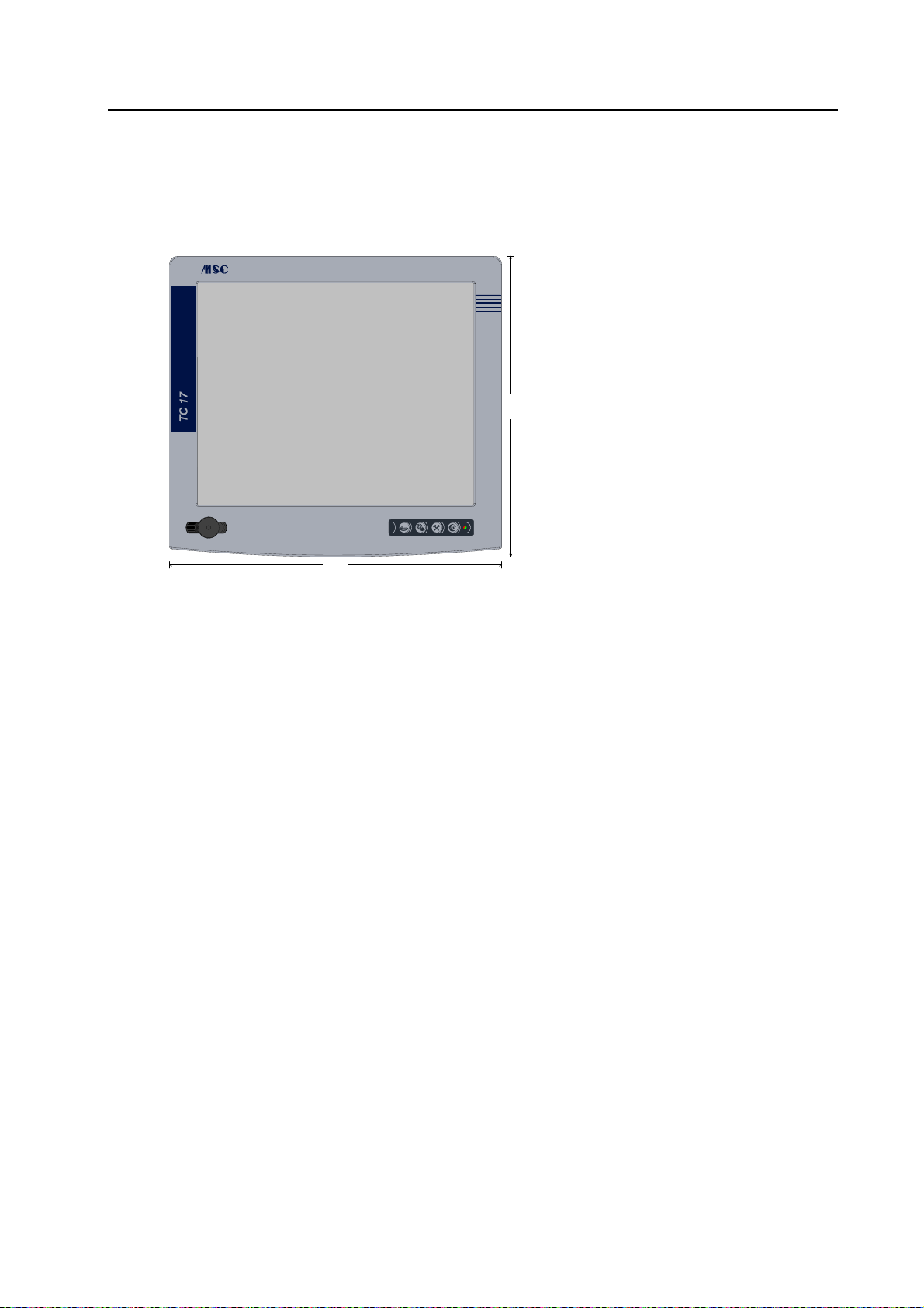
5.4 TC17-S
5.4.1 Front
• TC17-S
Stand-Alone = Add-on unit
• 410 mm x 370 mm
• 17.0" display
0
7
3
• Membrane keyboard
- 4 function keys
- LED
• 2 x USB under covering
341 x 273.5
a
b
c
• Touchscreen
410
Fig. 5-10: TC17-S [Stand-Alone] – Front
Rev. 1.00 dated 12.6.2006 Page 45 of 48
Page 50
Mechanical Dimensions TM: TC - Hardware
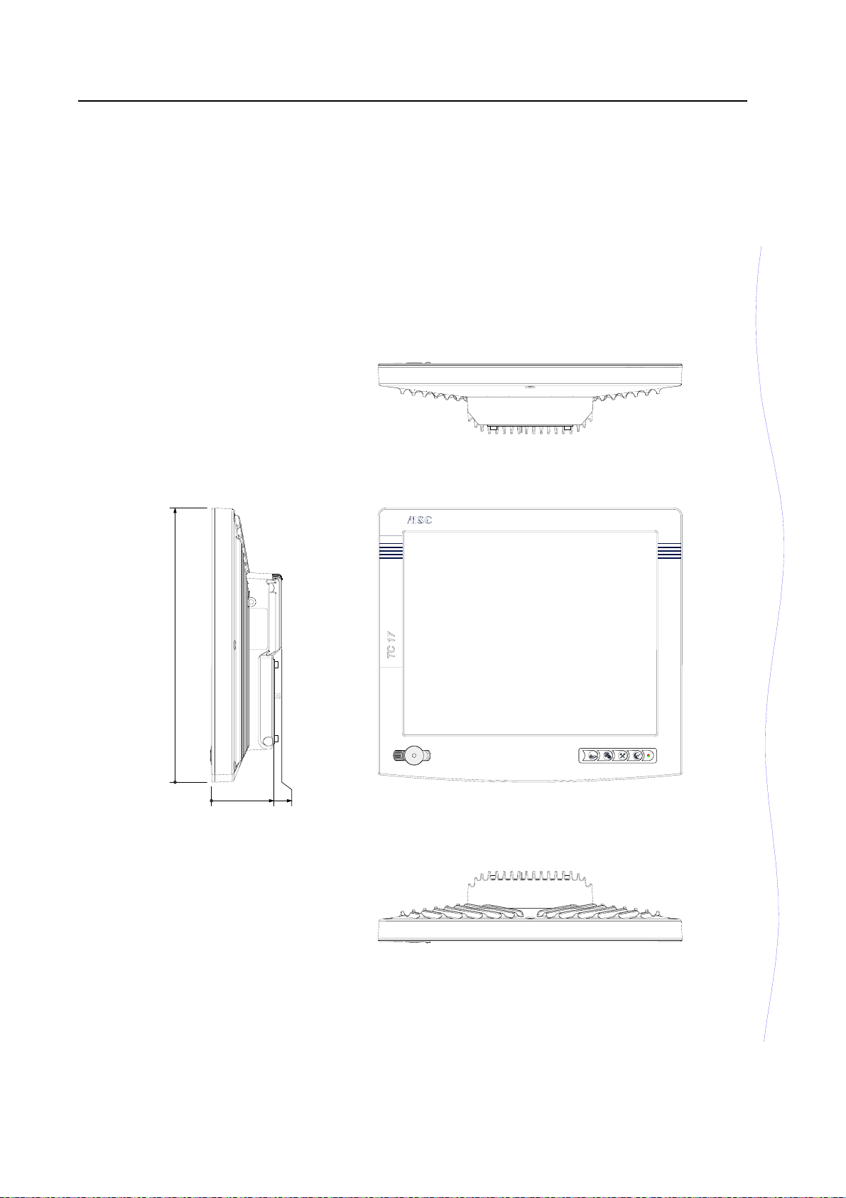
5.4.2 Device dimensions
TC17-S [Stand-Alone]
370
a
b
c
0
0
5
3
.
9
4
8
Page 46 of 48 Rev. 1.00 dated 12.6.2006
Page 51
TM: TC - Hardware Mechanical Dimensions
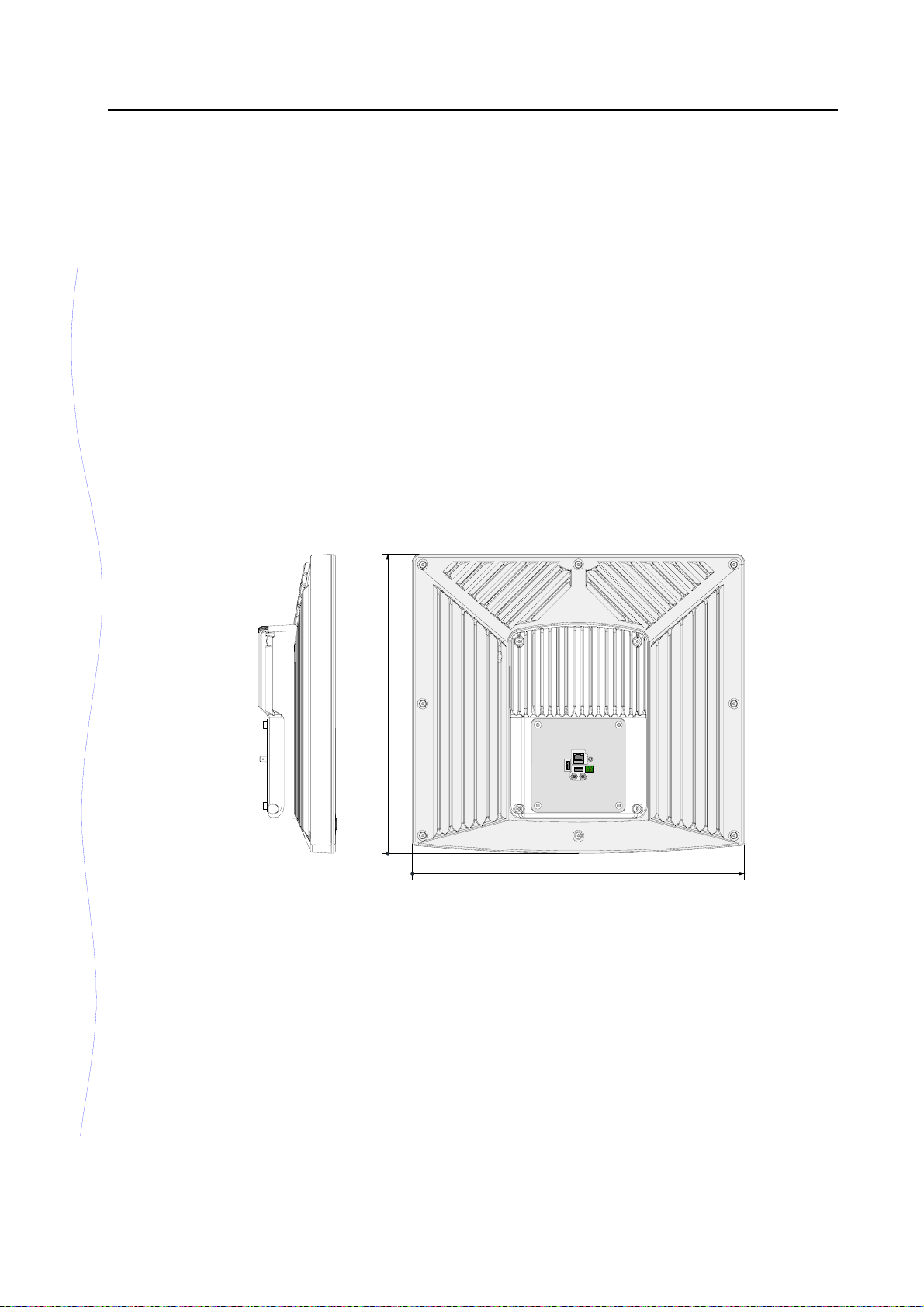
TC17-S [Stand-Alone]
370
0
0
General tolerances
ISO 2768 – mK
Fig. 5-11: TC17-S [Stand-Alone] – Device dimensions
0
1
4
Rev. 1.00 dated 12.6.2006 Page 47 of 48
Page 52
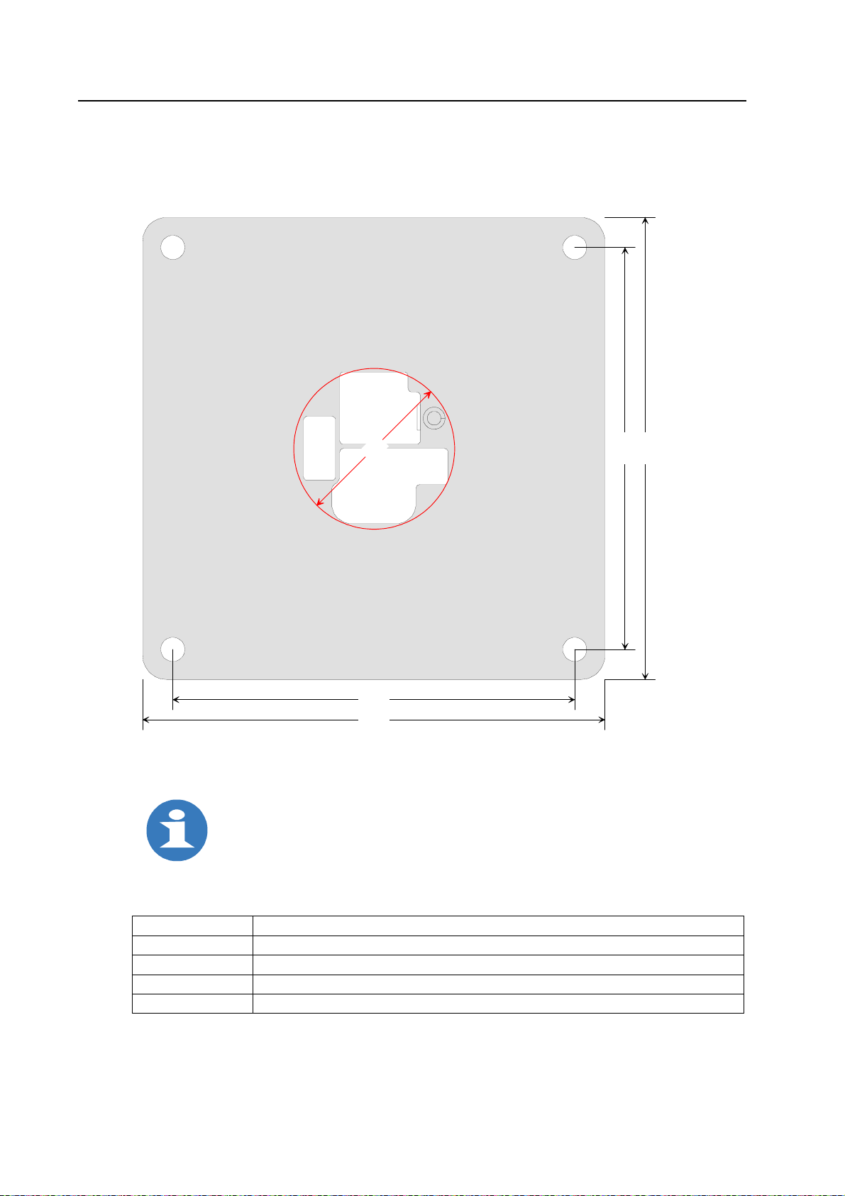
Mechanical Dimensions TM: TC - Hardware
5.4.3 Adapter plate
TC17-S [Stand-Alone]
for mounting a housing coupling
0
0
4
5
0
1
1
1
100
115
Material thickness: 2.5 mm
Fig. 5-12: TC17-S [Stand-Alone] – Adapter plate
Note:
When selecting a housing coupling (an equipment flange) it is to be ensured
that the tube internal diameter is at least 40 mm.
Upon request the adapter plate is provided with holes to mount the particular
flange system.
Possible standard flange systems
Manufacturer Indication
Rittal CP, CP-S (stainless steel), CP-S (angle coupling), CP-L (device coupling)
Bernstein CS-480 NR, CS-200 (SL), CS-600 NR (stainless steel)
ROSE GT48/2 (flange angle coupling), GT50/2, GT60/2, GTH48, GTH60
HASEKE KSE 60 (angle)coupling
Scale 1:1
Page 48 of 48 Rev. 1.00 dated 12.6.2006
 Loading...