

Page 1

OptiSwitch-100/100F
High Density 10/100/1000Mbps Switch
Installation and User Guide
ML43843 Rev.05
MRV Communications, Inc.
URL: http://www.mrv.com
Page 2

OptiSwitch-100/100F
Standards Compliance
UL 1950; CSA 22.2 No 950; FCC Part 15 Class A; CE-89/336/EEC, 73/23/EEC
FCC Notice
WARNING: This equipment has been tested and found to comply with the limits for a Class A digital device,
pursuant to Part 15 of the FCC Rules. These limits are designed to provide reasonable protection against harmful
interference when the equipment is operated in a commercial environment. This equipment generates, uses, and
can radiate radio frequency energy and, if not installed and used in accordance with the instruction manual, may
cause harmful interference to radio communications. Operation of this equipment in a residential area is likely to
cause harmful interference in which case the user will be required to correct the interference at his own expense.
The user is cautioned that changes and modifications made to the equipment without approval of the manufacturer
could void the user’s authority to operate this equipment
It is suggested that the user use only shielded and grounded cables when appropriate to ensure compliance with
FCC Rules.
CE Mark
The CE mark symbolizes compliance with the EMC directive of the European Community. Such marking is
indicative that the specified equipment meets or exceeds the following technical standards:
• EN 55022 - Limits and Methods of Measurement of Radio Interference Characteristics of Information
• EN 50081-1- Electromagnetic compatibility - of Radio Interference Characteristics of Information
• EN 50082-1 - Electromagnetic compatibility -- Generic immunity standard Part 1: Residential, commercial
• EN61000-4-2 (previously IEC 1000-4-2) - Electromagnetic compatibility for industrial-process measurement
• EN61000-4-3 (previously IEC 1000-4-3) - Electromagnetic compatibility for industrial-process measurement
• EN61000-4-4 (previously IEC 1000-4-4) - Electromagnetic compatibility for industrial-process measurement
• EN61000-4-5 - Electromagnetic compatibility for industrial-process measurement and control equipment
• EN61000-4-6 - Electromagnetic compatibility for industrial-process measurement and control equipment
• EN61000-4-8- Electromagnetic compatibility for industrial-process measurement and control equipment
• EN61000-4-11 – Electromagnetic compatibility for industrial-process measurement and control equipment
• EN61000-3-2 – Harmonic standard
• EN61000-3-3 – Voltage Fluctuation and Flicker standard
A ‘Declaration of Conformity’, in accordance with the above standards, has been made and is on file at MRV.
This document and the information contained herein are proprietary to MRV and are furnished to the recipient
solely for use in operating, maintaining and repairing MRV equipment. The information within may not be utilized
for any purpose except as stated herein, and may not be disclosed to third parties without written permission from
MRV. MRV reserves the right to make changes to any technical specifications in order to improve reliability,
function or design.
©2001 MRV Inc.
Technology Equipment
Technology Equipment Generic Emission standard Part 1 – Residential commercial and light industry
environment
and light industry environment
and control equipment Part 4: Section 2 - Electrostatic discharge requirements
and control equipment Part 4: Section 3 - Radiated electromagnetic field requirements
and control equipment Part 4: Section 4 - Electrical fast transient/burst requirements
Part 4: Section 5 – Surge Immunity requirements
Part 4: Section 6 – Immunity to conducted disturbances induces by radio frequency fields
Part 4: Section 8– Power frequency magnetic field immunity requirements
Part 4: Section 11 – Voltage dips short interruptions and voltage variations immunity requirements
• CISPR 22 - Radiated and Line-conducted Class A
• EN 60950 - ITE Safety
i
Page 3
OptiSwitch-100/100F
Table of Contents
INTRODUCTION .................................................................................................................................. 1
F
EATURE SUMMARY
Feature / Configuration.................................................................................................................... 1
Management ..................................................................................................................................... 2
A
PPLICATIONS
T
YPICAL CONFIGURATION
T
ECHNICAL SPECIFICATIONS
Additional Standards Compliance....................................................................................................3
INSTALLATION ...................................................................................................................................5
I
NSTALLING THE OPTISWITCH
Rack Mounting..................................................................................................................................5
Front Panel....................................................................................................................................... 5
Rear Panel........................................................................................................................................6
I
NSTALLING MODULES IN THE OPTISWITCH
The OptiSwitch-100/F Modules........................................................................................................7
C
ONNECTING POWER
Input Supply...................................................................................................................................... 8
Grounding.........................................................................................................................................8
Module Screws..................................................................................................................................8
C
ONNECTING ETHERNET DEVICES
Network Connections........................................................................................................................ 8
GETTING STARTED............................................................................................................................9
C
ONVENTIONS USED IN THIS MANUAL
C
ONNECTING TO THE MANAGEMENT PORT
L
OGGING INTO THE COMMAND LINE INTERFACE
S
ETTING THE
V
ERIFYING THE INSTALLATION
A
CCESSING THE COMMAND LINE INTERFACE REMOTELY
..............................................................................................................................1
.......................................................................................................................................2
.....................................................................................................................2
.................................................................................................................3
-100/F .................................................................................................... 5
-100/F ............................................................................... 6
............................................................................................................................7
........................................................................................................8
..................................................................................................9
...........................................................................................9
..................................................................................9
IP A
DDRESS
...................................................................................................................10
...........................................................................................................10
...................................................................11
COMMAND LINE INTERFACE....................................................................................................... 12
C
OMMAND STRUCTURE
E
NTERING COMMANDS
SYSTEM COMMANDS ...................................................................................................................... 15
C
OMMANDS SUMMARY
Viewing System Status .................................................................................................................... 15
Viewing the Self-Test Status............................................................................................................16
Enabling / Disabling the Self Test .................................................................................................. 16
Warm-Resetting the Device ............................................................................................................ 17
Cold-Resetting the Device ..............................................................................................................17
Getting the Last Error .................................................................................................................... 17
Resetting to Factory Default Configuration ...................................................................................17
Viewing the Software Filename......................................................................................................17
Setting the Software File Name ...................................................................................................... 19
Viewing the TFTP Server IP Address.............................................................................................19
Setting the TFTP Server IP Address...............................................................................................19
Setting the TFTP Server Mode ......................................................................................................19
Getting the TFTP Download Mode ................................................................................................20
Downloading the Software .............................................................................................................20
BASIC CONFIGURATION................................................................................................................21
C
ONSOLE COMMANDS
Accessing Keyboard Help............................................................................................................... 21
.......................................................................................................................12
.......................................................................................................................13
.......................................................................................................................15
.........................................................................................................................21
ii
Page 4
OptiSwitch-100/100F
Displaying the Logo........................................................................................................................22
Clearing the Screen ........................................................................................................................ 22
Logging In ......................................................................................................................................22
Logging Out.................................................................................................................................... 22
Setting the Page Size.......................................................................................................................22
Setting the Command Line Prompt.................................................................................................22
Setting the Prompt Attributes..........................................................................................................23
Setting the Display Message Attributes ..........................................................................................23
Setting the Text Display Attributes ................................................................................................. 23
Setting the Password ......................................................................................................................23
IP C
OMMANDS
Viewing Current IP Address........................................................................................................... 24
Viewing Current IP Configuration .................................................................................................25
Setting an IP Address .....................................................................................................................25
Setting IP Configuration................................................................................................................. 25
Erasing the IP Configuration ......................................................................................................... 26
Configuring a Gateway ..................................................................................................................26
Viewing the Gateway Address....................................................................................................................26
Setting the Gateway Address...................................................................................................................... 27
A
DDRESS RESOLUTION PROTOCOL
Deleting ARP Table Entries ...........................................................................................................28
Adding an ARP Table Entry ...........................................................................................................28
Viewing ARP Statistics ...................................................................................................................28
Enabling or Disabling the BOOTP.................................................................................................29
Setting the Bootp............................................................................................................................. 29
P
ORT CONFIGURATION
Viewing the Port Configuration......................................................................................................31
Setting the Port Configuration........................................................................................................31
Setting the Port Speed and Mode................................................................................................................ 31
Configuring the Giga Ethernet Redundant port ............................................................................. 32
Displaying the Gigabit Ethernet Redundant port ........................................................................................ 32
Setting the Gigabit Ethernet Redundant port .............................................................................................. 32
Setting the Port State .................................................................................................................................. 32
Flow Control ..................................................................................................................................32
Viewing Flow Control ................................................................................................................................ 33
Setting Flow Control................................................................................................................................... 33
Port Priority ................................................................................................................................................ 33
P
ORT TRUNKING
Etherchannel...................................................................................................................................34
Definitions: ................................................................................................................................................. 34
3 Main rules for the EC............................................................................................................................... 34
CLI commands ........................................................................................................................................... 34
Head of Line Block..................................................................................................................................... 35
....................................................................................................................................24
......................................................................................................28
........................................................................................................................29
.................................................................................................................................33
MAC-SECURITY................................................................................................................................. 36
C
OMMANDS SUMMARY
Setting the Security Port Configuration..........................................................................................36
Displaying the Port Configuration .................................................................................................36
Setting the MAC Security Level......................................................................................................37
Getting the MAC Security Level ..................................................................................................... 37
Getting the Security Entries............................................................................................................ 37
Getting the MS Entry ......................................................................................................................37
Searching for a MAC Security Address..........................................................................................38
Adding a MAC Security Entry ........................................................................................................ 39
Deleting a MAC Security Entry ......................................................................................................39
Clearing a MAC Security Entry...................................................................................................... 39
Modifying a MAC Security Entry ...................................................................................................39
Saving a MAC Security Table......................................................................................................... 40
SPANNING TREE PROTOCOL (STP)............................................................................................. 41
H
OW THE
STP T
.......................................................................................................................36
OPOLOGY STABILIZES
................................................................................................41
iii
Page 5
OptiSwitch-100/100F
S
PANNING TREE PARAMETERS
R
OOT BRIDGE
M
ANUALLY DESIGNATING A ROOT BRIDGE
S
ELECTING A DESIGNATED SWITCH/BRIDGE
T
OPOLOGY CHANGE NOTIFICATION
U
SING
S
PANNING TREE AND
S
PANNING TREE COMMANDS
Enabling / Disabling STP...............................................................................................................44
Viewing the Spanning Tree State....................................................................................................46
Viewing the Bridge Parameters...................................................................................................... 46
Configuring the Bridge...................................................................................................................46
Modifying the Bridge Priority .................................................................................................................... 46
Setting the Time Between Messages ..........................................................................................................48
Setting the Hello Time................................................................................................................................ 48
Setting the Forward Delay .......................................................................................................................... 48
Viewing STP Port Configuration.................................................................................................... 48
Setting Ports Configuration............................................................................................................ 49
Setting the Port priority............................................................................................................................... 49
Enabling/Disabling Spanning Tree On a Port.............................................................................................49
Changing the Path Cost............................................................................................................................... 50
SWITCHING DATABASE .................................................................................................................51
L
EARNING TABLE
Aging Configuration.......................................................................................................................51
Viewing the Aging Time ............................................................................................................................ 51
Setting the Aging Time............................................................................................................................... 52
Viewing an Individual Learning Table Entry ................................................................................. 52
Viewing a Range of Learning Table Entries................................................................................... 53
Deleting an Individual Learning Table Entry.................................................................................55
Deleting Learning Table Entries for a Port.................................................................................... 55
Deleting a MAC Address From the Learning Table.......................................................................56
Adding Static Entries......................................................................................................................56
......................................................................................................................................42
STP
TO MANAGE REDUNDANT LINKS
VLAN R
................................................................................................................................51
............................................................................................................42
........................................................................................42
.......................................................................................42
BPDU......................................................................................... 42
......................................................................................44
ESTRICTIONS
..............................................................................................................44
.......................................................................................44
VIRTUAL NETWORKING................................................................................................................ 57
Getting a VLAN Matrix...................................................................................................................58
Viewing the VLAN Mode ................................................................................................................ 58
Setting the VLAN Mode .................................................................................................................. 58
I
NTER-SWITCH
I
MPORTANT CONSIDERATIONS
Tag Field Format ...........................................................................................................................59
Principles of ISVLAN......................................................................................................................59
Viewing the ISVLAN Mode.............................................................................................................60
Setting a Tagged Port.....................................................................................................................60
Modifying the VLAN Tag................................................................................................................61
Removing a Tagged Port ................................................................................................................61
Modifying the VLAN Ports .............................................................................................................61
Server Port......................................................................................................................................61
Creating a Server Port ...................................................................................................................61
Removing a Server Port.................................................................................................................. 62
VLAN.................................................................................................................................................62
Creating VLAN ............................................................................................................................... 62
Viewing VLAN Configuration......................................................................................................... 63
Viewing an Individual VLAN Entry ................................................................................................63
Deleting a VLAN............................................................................................................................. 63
Modifying a VLAN Name................................................................................................................ 65
M
ANAGEMENT
Viewing the Management Tag ........................................................................................................ 65
Modifying the Management Tag..................................................................................................... 66
Deleting the Management from a VLAN.........................................................................................66
Creating a New VLAN Which Includes the Management Port....................................................... 66
VLAN.........................................................................................................................59
............................................................................................................59
VLAN ........................................................................................................................65
iv
Page 6
OptiSwitch-100/100F
Setting a Switch Priority Policy...................................................................................................... 67
Viewing the Switch Priority Policy................................................................................................. 67
Modify the VLAN priority...............................................................................................................67
S
AMPLE CONFIGURATION
Physical Configuration Schema ..................................................................................................... 68
VLAN Server Port Configuration ...................................................................................................68
VLAN configuration........................................................................................................................69
Payroll VLAN Configuration ..................................................................................................................... 69
Finance VLAN Configuration ....................................................................................................................69
Checking the Configuration............................................................................................................69
VIRTUAL BROADCAST DOMAIN..................................................................................................70
VBC M
Viewing the VBC Mode...................................................................................................................70
Setting the VBC Mode.....................................................................................................................70
Creating VBC Domains..................................................................................................................70
Viewing the VBC Table...................................................................................................................71
Deleting a VBC............................................................................................................................... 72
UTILITIES............................................................................................................................................ 73
P
ING COMMANDS
Starting Ping................................................................................................................................... 73
S
TOPPING PING
P
ORT MIRRORING
Setup ............................................................................................................................................... 74
F
RAME GENERATOR
Setting the Frame Generator..........................................................................................................75
Starting Frame Generation ............................................................................................................77
Stopping Frame Generation ...........................................................................................................77
.........................................................................................................................................70
ODE
................................................................................................................................73
....................................................................................................................................74
................................................................................................................................74
Setting the Monitoring Port ........................................................................................................................74
Monitoring a Port........................................................................................................................................ 74
Saving the Configuration............................................................................................................................75
Stopping Monitoring................................................................................................................................... 75
Viewing the NVRAM Configuration.......................................................................................................... 75
Erasing the NVRAM Configuration ........................................................................................................... 75
– VLAN/S
............................................................................................................................75
ERVER-PORT/TRUNKING PORT
..................................................68
SNMP..................................................................................................................................................... 78
NB
ASE-XYPLEX
SNMP B
SNMP Community String Commands............................................................................................. 78
Viewing the Community String..................................................................................................................79
Setting the Read or Write Community........................................................................................................ 79
SNMP T
STATISTICS ........................................................................................................................................84
C
V
G
R
TROUBLESHOOTING....................................................................................................................... 88
C
RAPS
Setting Authentication Traps .......................................................................................................... 80
Viewing the Authentication Trap Status..................................................................................................... 80
Enabling/Disabling the Authentication Trap...............................................................................................81
Configuring the Trap Stations ........................................................................................................81
Viewing the Stations List............................................................................................................................ 81
Adding a Station to the List ........................................................................................................................ 81
Deleting a Station From the List................................................................................................................. 83
LEARING THE SWITCH COUNTERS
IEWING STATISTICS ON A PARTICULAR PORT
ETTING COLLISIONS ON A PORT
MON STATISTICS
Viewing Rmon Statistics Group for a Port ................................................................................................. 85
Getting the Packet Size Distribution ........................................................................................................... 86
Viewing the Management Counters............................................................................................................ 86
ONTACTS
SNMP S
ASIC CONFIGURATION
......................................................................................................................................80
...........................................................................................................................................88
UPPORT
...............................................................................................................................85
.......................................................................................................78
...........................................................................................................78
.....................................................................................................84
....................................................................................84
........................................................................................................85
v
Page 7
OptiSwitch-100/100F
APPENDIX A: CONSOLE COMMAND LINE QUICK REFERENCE ........................................89
Commands Groups ......................................................................................................................... 89
Console Commands........................................................................................................................89
System Commands ..........................................................................................................................90
IP Commands ................................................................................................................................. 90
Ping Commands..............................................................................................................................90
Address Resolution Protocol .......................................................................................................... 92
SNMP..............................................................................................................................................92
Switching ........................................................................................................................................ 92
Virtual Networking ......................................................................................................................... 93
Port Monitoring.............................................................................................................................. 94
EtherChannel Command ................................................................................................................94
MAC Security..................................................................................................................................94
Port Configuration .........................................................................................................................95
Statistics.......................................................................................................................................... 95
Spanning Tree Protocol (STP)........................................................................................................96
APPENDIX B: SYSTEM DEFAULT VALUES................................................................................ 97
console............................................................................................................................................97
system .............................................................................................................................................97
snmp................................................................................................................................................97
switch-db ........................................................................................................................................97
port configuration........................................................................................................................... 97
spanning tree .................................................................................................................................. 97
APPENDIX C: FIRMWARE DOWNLOAD VIA TFTP................................................................ 101
D
OWNLOADING ‘CLIENT MODE
D
OWNLOADING ‘SERVER MODE
TFTP R
ECOVERY
- B
REAKING INTO THE BOOT
’.......................................................................................................101
’ ...................................................................................................... 101
ROM........................................................................ 101
vi
Page 8
OptiSwitch-100/100F
Introduction
The OptiSwitch-100/F is a robust switch platform, representing the next generation in
switching technology. It boasts a combination of cutting-edge hardware architecture, a rich set
of Virtual LAN (VLAN) options and advanced network management features.
The functional difference between the OptiSwitch-100 and the OptiSwitch-100F is that the
latter supports one high density fiber optic module in the free slot and is slightly taller.
Feature Summary
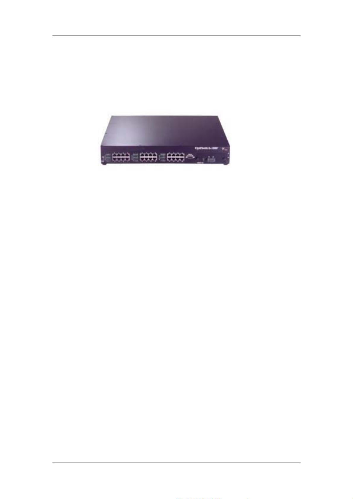
Figure 1: General view OptiSwitch-100/F
Feature / Configuration
24 switched 10/100Mbps ports and a slot (dport) to accommodate one of the following
•
uplink modules:
Single Gigabit Ethernet port (MM,SM)
•
Dual Gigabit Ethernet ports (MM,SM)
•
8 10/100 auto-negotiation ports module
•
2,4 or 8 100Base-FX ports (MM,SM)
•
2,4 Ethernet module
•
The highest common port speed is automatically set with when connecting any standard
•
compliant (802.3u Auto-negotiation) network device or station
Each 10/100Base port operates in half duplex mode, for shared networks, or in a dedicated
•
full duplex link, running at up to 200Mbps
All ports support auto-polarity detection and correction
•
Store-and-Forward switching
•
Flow Control (IEEE 802.3x) provides effective packet loss protection under heavy load
•
conditions, minimizing delays and retransmission of data, thus improving network
performance
Port-Trunking/ Etherchannel (available in the next software release) which enables
•
multiple ports to combine their bandwidth and operate as a single logical link. These
features can be used to create a high speed backbone connection between switches
Supports the creation of up to 2000 Virtual LAN
•
Supports the Inter-Switch VLAN tagging standard which enables the creation of multiple
•
groups across the network (IEEE 802.1q)
MAC address table (up to 12K unicast entries)
•
Maximum wire speed throughput on all ports simultaneously
•
1
Page 9
OptiSwitch-100/100F
Supports RMON (groups 1,2,3,9), Telnet for rapid fault detection and isolation
•
Port Mirroring
•
Spanning Tree Algorithm prevents broadcast loops
•
Management
•
•
•
Applications
A switch boosts network performance by segmenting a single large collision domain into
smaller, separate collision domains. It also provides dedicated connections for heavily loaded
networks using work stations and servers. In addition, the Full Duplex capability of Ethernet
switches permits long distance connectivity for backbone applications or high throughput for
high-performance dedicated servers. The OptiSwitch-100/F combines 10/100Mbps switched
ports with a slot (dport) for accommodating an optional module.
Fully managed through the comprehensive
Network Management System, or any SNMP-based management platform
Extensive Command Line Interface (CLI) management provides out-ofband administration.
Supports
status of each port is displayed by a LED on the front panel,
indicating active and link status.
private MIB, Ethernet MIB and bridge MIB.. The
MRV’s
MRV
MegaVision
Typical Configuration
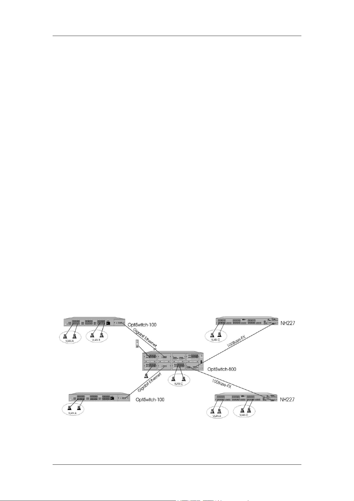
The OptiSwitch-100/F switch can connect up to twenty-four 10/100Mbps ports and with a slot
(dport) for accommodating an optional module Figure 2 illustrates various connection
possibilities: Two OptiSwitch-100/F switches ,with Gigabit Ethernet uplink modules, located
in different buildings can be connected via MM or SM fiber optic cable to a Gigabit Ethernet
backbone. VLAN Tagging allows the creation of one logical VLAN across all switches.
Additional connections include dedicated 10/100Mbps workgroup connections and 100Mbps
dedicated servers.
Figure 2: Various Application Possibilities Of The OptiSwitch-100/F
2
Page 10

OptiSwitch-100/100F
Technical Specifications{xe "Technical
Specifications"}
Compatibility IEEE802.3z (Gigabit Ethernet), IEEE802.3u (Fast Ethernet),
Input Voltage (V) 100-240 VAC ± 10%
AC Line Frequency (Hz) 50-60 Hz 50-60 Hz
Min. Power Consumption (W) 40 40
Max. Power Consumption (W) 65 65
Physical Height 1U 1.5U
Size W x D x H (mm) 443 x 312 x 44.5 443 x 362 x 66.5
Size W x D x H (inches) 17.4 x 12.3 x 1.8 17.4 x 14.2 x 2.6
Weight (kg) 2.0kg 3.2kg
Weight (lbs.) 4.4lbs 7.7lbs
Operating Temperature (C )
Operating Temperature (F)
Storage Temperature ( C)
Storage Temperature (F)
Humidity 85% maximum, non-condensing
Diagnostic LEDs Per Port LEDs: Port Activity, Link status ; Per Unit LEDs:
Mounting 19-inch rack mount EIA RS-310C standard
Standards Compliance UL-1950, TUV, CSA-22.2 No. 950 ; VCCI ; FCC Part 15, Class
OptiSwitch-100/F OptiSwitch-100/FF
IEEE802.1d (Bridge/Spanning tree), IEEE 802.1q (Vlan
Tagging), IEEE802.1p (Priority Queuing), IEEE802.3x (Flow
Control), Ethernet MIB, Bridge MIB, RMON (4 Groups)
0°C - 40°C 0°C - 40°C
32°F - 104°F 32°F - 104°F
-10°C - 50°C -10°C - 50°C
14°F - 122°F 14°F - 122°F
Power Status, Management
A, CE
Additional Standards Compliance
* The OptiSwitch-100/F contains a built-in SNMP agent running on the SNMP Processor
Board. This allows each unit to be managed from a centralized management station via
any SNMP-compliant NMS.
The SNMP agent software complies with the following standards:
• RFC 1155
May 1990
• RFC 1212
• RFC 1213 -
• RFC 1284
• RFC 1286
• RFC 1757
The OptiSwitch-100/F also supports two
The SNMP agent utilizes UDP/IP (RFC 768, RFC950, RFC1071 and RFC791) as OSI layers
3 and 4 protocols, ICMP (RFC792) and ARP (RFC826) to complete the UDP/IP protocol
suite.
- The Structure of Management Information (SMI) for TCP/IP Based Internets,
- The Management Information Base I (MIB I)
The Management Information Base II (MIB II), March 1991.
- The Ethernet MIB
- The Bridge MIB
- The RMON MIB
private MIBs: switch mib and gswitch.mib.
MRV
3
Page 11

OptiSwitch-100/100F
The UDP/IP stack implementation conforms to:
• RFC 1122 -
• RFC 1123 -
Requirements for Internet hosts - communication layers.
Requirements for Internet hosts - application and support
The OptiSwitch-100/F may be managed by any SNMP Manager that conforms to the above
standards. It may be fully managed by MegaVision,
MRV’s
multi-platform network
management system. For more information on MegaVision, view our web site, or contact
MRV for a data sheet.
The OptiSwitch-100/F implements an MRV Enterprise MIB and an MRV Product MIB that
may be provided upon request.
4
Page 12
OptiSwitch-100/100F
Installation
The OptiSwitch-100/F can operate as a stand-alone unit or in conjunction with any of MRV’s
other Ethernet offerings. Switch management is through MRV MegaVision software, any
SNMP-compatible NMS, or through the Command Line Interface (CLI).
Installing the OptiSwitch-100/F{xe "NH2064:installing
the"}
This section outlines the installation and operation of the OptiSwitch-100/F.
The OptiSwitch-100/F comes as a 19” rack-mountable unit. However, it can be placed either
in a rack mount, using the enclosed rack-mount brackets, or on a secure flat surface. Ensure
that the unit is within reach of the necessary connections (i.e. power outlet, Ethernet
connections, and if the OptiSwitch-100/F will be monitored via the serial port, a PC, UNIX
workstation, or modem). The unit is powered by a wide-range power supply for either 110 or
220 VAC operation.
WARNING!
Free airflow must be maintained in order to permit adequate cooling of the unit. Do NOT
block any of the unit’s ventilation holes!
Rack Mounting{xe "Rack Mounting"}{xe "NH2064:rack
mounting"}
If rack mounted units are installed in a closed or multi-unit rack assembly, they may require
further evaluation by Certification Agencies. The following items must be considered.
1. The ambient within the rack may be greater than room ambient. Installation should
2. Installation should be such that a hazardous stability condition is not achieved due to
be such that the amount of air flow required for safe operation is not compromised.
The maximum temperature for the equipment in this environment is 50C.
Consideration should be given to the maximum rated ambient.
uneven loading.
Front Panel{xe "Front Panel"}
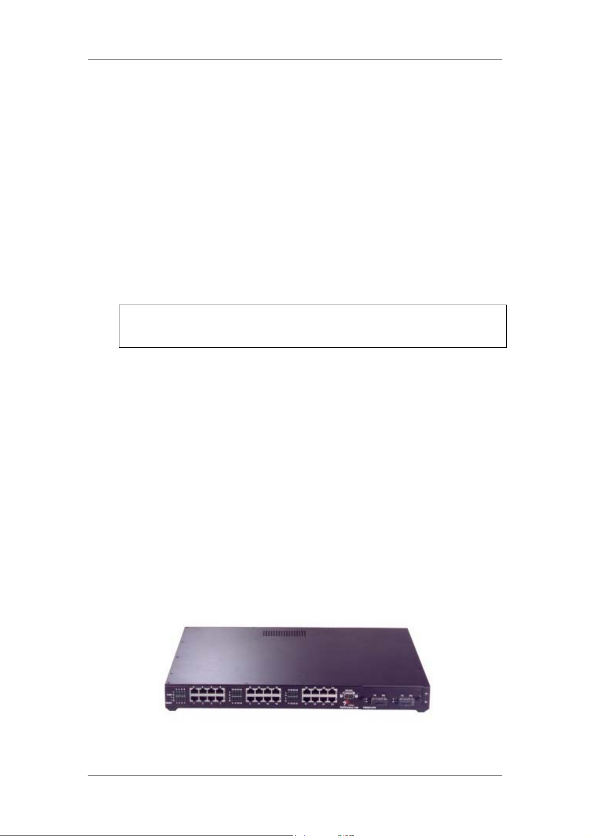
The front panel of the OptiSwitch-100/F is illustrated below in Figure 3. The table below
describes its various components, LED indications and their functions.
Figure 3: Front Panel View OptiSwitch-100
5
Page 13
OptiSwitch-100/100F
OptiSwitch-100/F Front Panel Table{xe "NH2064 Front Panel Table"}
1. Module Panel
2. DB-9 Connector
3. Global LEDs
PWR
MGMT
One of eight module slots
RS-232 connection for Command Line Interface
management
Green ON
Green
= power up
= power down
OFF
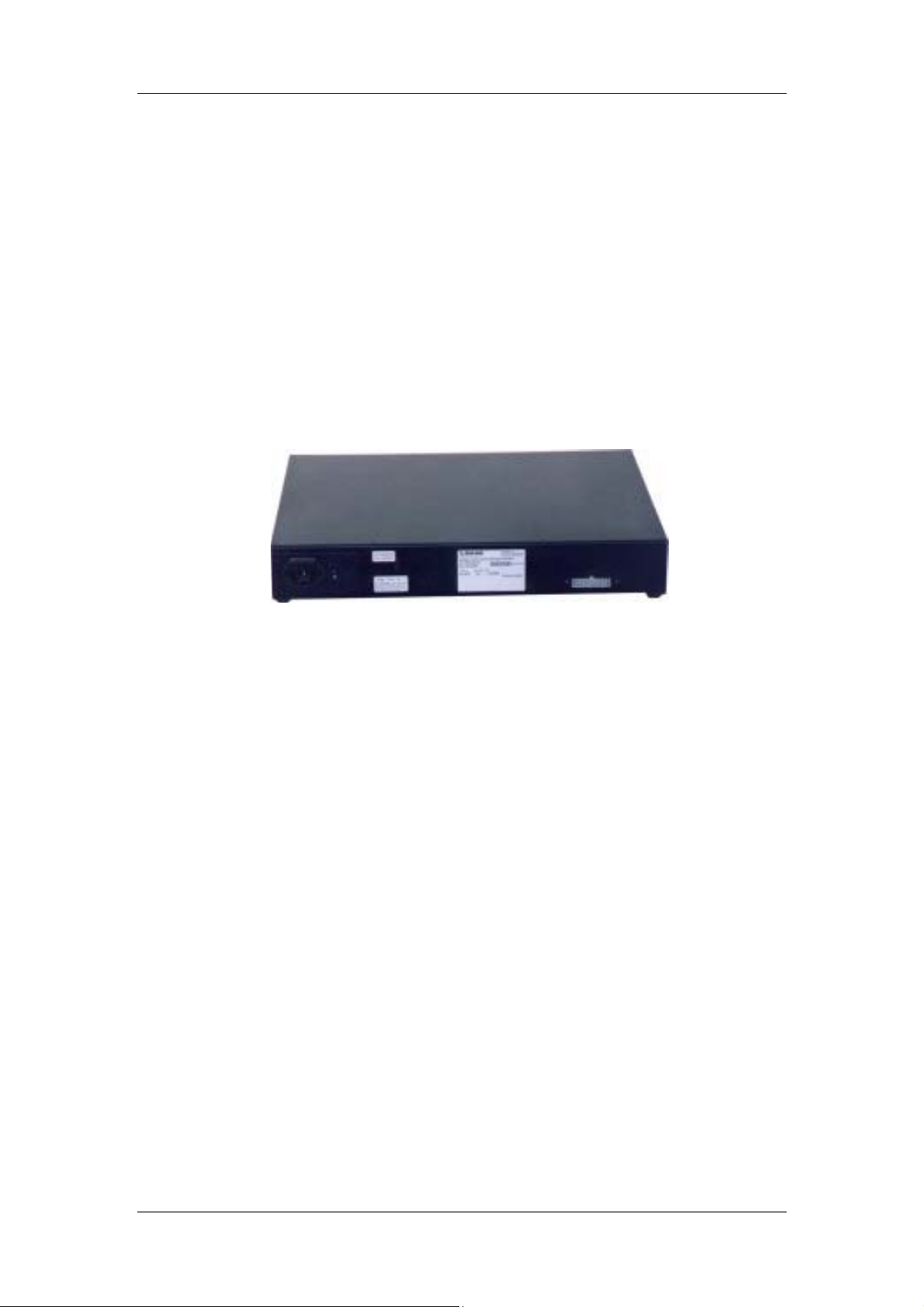
Rear Panel{xe "Rear Panel"}
The rear panel of the OptiSwitch-800/R, which houses the power connection and ON/OFF
switch, is illustrated in Figure 4. Fan holes are located on the left side of the unit (MUST NOT
OBSTRUCTED).
Figure 4: Rear Panel View OptiSwitch-100/F
Installing Modules in the OptiSwitch-100/F{xe
"NH2064:installing the modules"}
The modules are field-installable modules. Follow the procedure below to ensure proper
installation:
1. Power OFF the OptiSwitch-100/F switch.
2. Carefully slide an OptiSwitch-100/F module into a free slot and press firmly to insert.
3. Tighten the thumb screws securely.
4. Power ON the OptiSwitch-100/F switch.
6
Page 14

OptiSwitch-100/100F
The OptiSwitch-100/F Modules
All modules fit in all the chassis except for the 2GE which only compatible with the
OptiSwitch-800.
Connecting Power {xe "Power Connection"}
The power cord should be plugged into an easily accessible outlet. A built-in power supply
automatically adjusts to any outlet providing between 90 VAC and 264 VAC at 50/60 Hz.
For a 115 volt configuration, the power cord to be used is minimum type SJT (SVT) 18/3,
rated 250 Volts AC, 10 Amps with a maximum length of 15 feet. One end is terminated in an
IEC 320 attachment plug, the other in a NEMA 5-15P plug.
The power cord to be used with a 230 Volt configuration is minimum type SJT (SVT) 18/3,
rated 250 Volts AC, 10 Amps with a maximum length of 15 feet. One end is terminated in an
IEC 320 attachment plug. The other end is terminated as required by/ the country where it will
be installed.
FRANÇAIS
Utilisez uniquement un câble secteur adapté à 230 volts, de type SJT (SVT) 18/3 minimum, 250 volts AC
nominal, 10 Amps, et d’une longueur maximale de 4.5m. l’une des extrêmités étant raccordée à un
connecteur Type IEC320, tandis que l’autre extrêmité correspondra aux spécifications du pays
concerné.
DEUTSCH
Das Netzkabel ist das hauptsachliche Diskonnektionsmittel, es sollte in eine leicht erreichbare steckdos
gesteckt werden. Das Netzkabel kann mit einer 230 Volts Konfiguration verwonder werden vom typ:
Minimum VDE or HAR, 3 X 1.00 mm2, 250 VAC, 10 Amps, maximal 4.5m long. Ein Ende ontspriche
dem Stecker IEC 320. Das andere Ende entspricht den Anfoderungen des entsprechenden Landes.
7
Page 15
OptiSwitch-100/100F
Input Supply{xe "Input Supply"}
Check nameplate ratings to assure there is no overloading of supply circuits that could have an
effect on overcurrent protection and supply wiring.
Grounding
Reliable earthing of this equipment must be maintained. Particular attention should be given
to supply connections when connecting to power strips, rather than direct connections to the
branch circuit.
Module Screws
Securely tighten all screws to a minimum of 4.5 in-lb.
Connecting Ethernet Devices{xe "Connecting the
Ethernet Devices"}
For optimum performance, the Ethernet segments connected to the OptiSwitch-100/F must be
configured carefully. Generally, the segments should be configured so those machines on a
given port communicate primarily among themselves; i.e. most traffic does not need to cross
the switch. However, this is not the best configuration for certain situations.
Network Connections{xe "Network Connections"}
The cable connections to the 10/100BaseTX ports can be UTP or STP Category 5 and above,
and cable length is limited to 100 meters on each port. STP cable carries a higher quality of
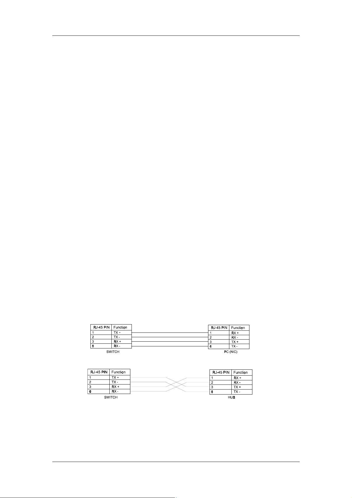
signal and is less sensitive to environmental noise. The RJ-45 ports of the switch are defined
as MDI-X ports.
The 10/100BaseTX ports on the OptiSwitch-100/F are designed to be connected directly to a
workstation, using a standard straight through patch cable. In order to cascade switches or
connect a hub to the switch, a crossover cable must be used.
Figure 5: Straight cable connection between a OptiSwitch-100/F and a workstation
Figure 6: Crossover cable connection between an OptiSwitch-100/F and a hub
8
Page 16

OptiSwitch-100/100F
Getting Started
Conventions Used in this Manual
The following are conventions used to explain command usage in this manual:
Enter commands by typing the command name followed by one or more parameters (if
•
required) and pressing the Enter key. For example, typing
Enter key at the command prompt displays the Administrative Interface banner.
banner
and pressing the
Items printed in the
•
Courier font in a box
The is used to show examples of CLI screen output.
•
The
•
•
Courier Italicized font
values. For example,
123.1.2.3.
Items in {} and separated by
Example :
get-comm { read | write | *}
This means you can type one of the following:
get-comm read
get-comm write
get-comm *
Courier bold font
represents command variables (arguments) and
represents an IP address in dotted decimal notation as
IP address
represent alternatives for the argument.
|
are to be typed exactly as they appear.
Connecting to the Management Port{xe "management
port:connecting to"}
With the product we supply a management cable. You can use it to get access to the
management port.
To configure the serial ports do the following items:
Connect the cable provided to the management port and communication interface (COM1
•
or COM2) of your PC.
Start Windows HyperTerminal and create a new connection with the property set to
•
9600 bits per second, 8 bits per character and no flow control.
Start HyperTerminal session and then type Enter to get the login prompt.
Logging into the Command Line Interface{xe
"command line interface:logging into the"}
The Command Line Interface (CLI) is protected with a login name and password.
To access the CLI the Network Administrator has to provide his name and a password.
Please Login
username: don
password: (not echoed)
The factory default password is a null string. To log in just press the Enter key. Once you are
logged into the CLI, you may change the password to avoid unauthorized access.
9
Page 17

OptiSwitch-100/100F
Setting the IP Address{xe "IP Address:setting the"}
To manage the MegaSwitch using an SNMP Network Management Application or to use the
ping command to test the switch, it is necessary to assign an IP Address, a netmask and a
broadcast address. The Network Administrator should assign the IP address in accordance
with the existing IP addressing schema.
set-ip-cfg
NOTE:
set-ip
Set the IP configuration with the
according to the IP address class.
SYS_console> set-ip-cfg?
set-ip-cfg set IP addres, Netmask, Broadcast
[arg #0] IP address
[arg #1] Netmask
[arg #2] Broadcast
An example of this is the following:
SYS_console> set-ip-cfg 192.1.1.64 255.255.255.0 255.255.255.255
If the switch has no IP Address, then the provided IP Configuration will change the running parameters
as well as the NVRAM-based database. If the switch was already configured, the command will only
change the NVRAM database. Consequently, to use the new parameters you should reset the Switch,
using the warm-reset command.
You can also use the simplified command. In this particular case, the mask and broadcast are
automatically set to defaults according to the IP address class.
SYS_console> set-ip?
set-ip set IP address
[arg #0] IP address
An example of this is the following:
SYS_console> set-ip 192.1.1.64
set-ip-cfg
command. automatically set to defaults
Verifying the Installation{xe "Installation:testing the"}
After the installation is complete and the IP Address configured, use the utility ping to test the
connectivity (For information on ping, refer to the utilities chapter).
ping
The ping command sends an echo request to the host specified in the command line. For
example, to test connectivity from the Switch to a workstation with an IP Address of
192.1.1.1, use the following command:
10
Page 18

OptiSwitch-100/100F
SYS_console>ping?
ping ip traffic generator
[arg #0] destination IP address
[arg #1] Number of packets to send or 0 for less ping
An example of this is the following:
SYS_console> ping 192.1.1.1 100
Accessing the Command Line Interface Remotely{xe
"Accessing the Command Line Interface Remotely"}
When the switch has an IP address, the administrative interface can be accessed by remote
through Telnet. All commands work exactly as if the serial interface were being used. Please
note that only one console session may be active at any given time. This means that after the
first Telnet session is established, all other Telnet connections are refused until the current
session is closed.
11
Page 19

OptiSwitch-100/100F
Command Line Interface
The CLI provides the following: {xe "command line interface (CLI)"}
Configuration of system parameters, including the serial line and / or the console’s
•
parameters
Configuration of the switch’s SNMP Agent parameters
•
Configuration of the ports’ parameters.
•
Network performance monitoring.
•
Virtual LANs operations
•
Statistics operations
•
Spanning Tree operations
•
Command Structure{xe "command line
interface:command structure"}
The CLI has several categories of commands:
Console related commands: help, banner, console parameters setup, etc.
•
System related commands: reset commands, download commands, initialize the NVRAM
•
with defaults, etc.
IP commands: parameter setup, parameter and information display, etc.
•
SNMP agent related commands: parameter setup, management and traps options
•
Switching Database related commands: aging time management and Switching Database
•
entry management
Virtual LAN commands
•
Port Configuration related commands
•
Switching statistics commands
•
Spanning Tree related commands
•
See the quick reference at the end of this manual for the command list sorted by subject.
at the CLI prompt displays a list of all the available command topics and a short
Typing
explanation about each. Typing in one of the names off this list yields a list of the commands
under that topic.
SYS_console>?
Commands groups are:
---------------------- console Console related commands
system System related commands
ip IP related commands
snmp SNMP related commands
switch-db Switching Database related commands
vlan Virtual LANS related commands
echannel EtherChannel Commands
mac-security MAC security related commands
port-cfg Port Configuration related commands
statistics Switching Statistics related commands
sp-tree Spanning Tree related commands
-----------------------------------------------------------------------------
use ! for previous cmd, ^U to clear line, ^W to clear previous word
-----------------------------------------------------------------------------
Note: ^ = CTRL key
?
12
Page 20

OptiSwitch-100/100F
Entering Commands{xe "command line
interface:entering commands"}
Enter commands by typing the command name followed by one or more parameters (if
required) and pressing the Enter key. For example, typing
key at the command prompt displays the Administrative Interface banner.
If a command is entered incorrectly, a message is displayed indicating the type of error that
occurred. For example, typing a nonexistent command gives the following message:
SYS_console> pin
command <pin> not found
If the command exists but the number of parameters is incorrect, the following message is
displayed:
SYS_console> ping
too few arguments <0 <2
To get the syntax and explanation of a command, type a question mark
name:
SYS_console> ping ?
ping IP traffic generator
[arg #0] destination IP address
[arg #1] number of packets to send or 0 for endless ping
SYS_console> ping _
banner
and pressing the Enter
After the command
?
that the command is repeated after the prompt, and you have only to add the necessary
Note
parameter/s. If you add a question mark after the first parameter, the same explanation is
provided and the previous command is redisplayed, including the provided parameters.
SYS_console> ping 129.1.1.7 ?
ping IP traffic generator
[arg #0] destination IP address
[arg #1] number of packets to send or 0 for endless ping
SYS_console> ping 129.1.1.7 0
The CLI provides a history of the last commands. Type
or Ctrl-P at the prompt to recall the
!
last command in the command history.
To correct a command line, use the following special keys (see the
or CTRL - P
!
CTRL - W
CTRL - U
- call the previous command
- delete the previous word
- erase the entire line
help-kbd
command):
When a command has more than one screen-full of text to print, you can continue to scroll or
stop the process.
The
Courier Italicized font
For example,
Ipaddress
represents an IP address in dotted decimal notation as 123.1.2.3.
represents command variables (arguments) and values.
Items in {} and separated by
Example :
get-comm { read | write | *}
represent alternatives for the argument.
|
This means you can type one of the following:
13
Page 21

OptiSwitch-100/100F
get-comm read
get-comm write
get-comm *
To retrieve a list of commands with a common beginning, type the first keyword(s), followed
by a question mark. For example:
sys_console>get ? .
Commands matching <get->
-------------------------------------------------------------------- get-stst-level show the selftest level
get-last-err displays information about the last fatal error
get-sw-file retrieves the SNMP Agent Software file name
get-tftp-srvr retrieves the TFTP download server IP address
get-tftp-mode retrieves the TFTP download mode
get-ip show current IP address
get-ip-cfg show current IP configuration
get-gatew show default gateway
get-arp-tbl display the ARP table
get-arp-stats get ARP statistics
get-bootp retrieves the state of the BOOTP process
get-comm show current read or/and write community
get-auth shows the traps authentication mode
get-traps show destination stations in the trap list
get-lt-16 gets 16 LT entries starting at a given index
get-lt-entry gets an LT entry at index
get-hdw-vlan get VLAN entry from switching hardware
get-lt-age retrieves the LT aging period
--Hit any key for more...<’q’-for quit, Esc-for paging cancel>
sys_console>
14
Page 22

OptiSwitch-100/100F
System Commands
Commands Summary{xe "system commands"}
The System Commands let you display and set the system-related parameters. Type system to
display system related commands.
sys_console>system
System related commands
---------------------------------------------------------------------
sys-stat show system status
get-stst-level show the selftest level
set-stst-level change the selftest level
warm-reset warm reset of the device
cold-reset cold reset of the device
get-last-err displays information about the last fatal error
init-nvram initialize NVRAM to default values
get-sw-file retrieves the SNMP Agent Software file name
set-sw-file sets the SNMP Agent Software file name - for download
get-tftp-srvr retrieves the TFTP download server IP address
set-tftp-srvr sets the TFTP download server IP address
set-tftp-mode sets the TFTP download mode
get-tftp-mode retrieves the TFTP download mode
sw-dnld software download BY TFTP
set-fg-param sets the Ethernet frame generator parameters
start-fg starts the Ethernet frame generator
stop-fg stop the Ethernet frame generator
sys_console>
Viewing System Status{xe "system commands:viewing
system status"}
sys-stat
This command displays general status information about the Ethernet Switch and its SNMP
Agent Hardware and Software:
SYS_console>sys-stat
MRV OptiSwitch-800 Version 2.24
Tue Apr 20 14:47:06 1999
SNMP Object ID is : < 1.3.6.1.4.1.629.16.3.1 >
System MAC Address : 00-20-1a-00-e1-f4
Switching Data Base Size: 12288 entries
Number of ports : 64
Total uptime(hundredths of seconds ): 331200
Total uptime(days, hh:mm:ss format): 0 days, 0:55:12.00
Mainboard hardware: Revision 0
Management card revision: i960-Jx
Slots hardware revisions -
i/f 1 : description [Port 1 - 10/100 BaseTx ETHERNET Port] : status [UP]
i/f 2 : description [Port 2 - 10/100 BaseTx ETHERNET Port] : status [UP]
i/f 3 : description [Port 3 - 10/100 BaseTx ETHERNET Port] : status [UP]
i/f 4 : description [Port 4 - 10/100 BaseTx ETHERNET Port] : status [UP]
i/f 5 : description [Port 5 - 10/100 BaseTx ETHERNET Port] : status [UP]
i/f 6 : description [Port 6 - 10/100 BaseTx ETHERNET Port] : status [UP]
15
Page 23

OptiSwitch-100/100F
i/f 7 : description [Port 7 - 10/100 BaseTx ETHERNET Port] : status [UP]
i/f 8 : description [Port 8 - 10/100 BaseTx ETHERNET Port] : status [UP]
i/f 9 : description [Port 9 - 10/100 BaseTx ETHERNET Port] : status [UP]
i/f 10 : description [Port 10 - 10/100 BaseTx ETHERNET Port] : status [UP]
i/f 11 : description [Port 12 - 10/100 BaseTx ETHERNET Port] : status [UP]
i/f 13 : description [Port 13 - 10/100 BaseTx ETHERNET Port] : status [UP]
i/f 14 : description [Port 14 - 10/100 BaseTx ETHERNET Port] : status [UP]
i/f 15 : description [Port 15 - 10/100 BaseTx ETHERNET Port] : status [UP]
i/f 16 : description [Port 16 - 10/100 BaseTx ETHERNET Port] : status [UP]
i/f 17 : description [Port 17 - 10/100 BaseTx ETHERNET Port] : status [UP]
i/f 18 : description [Port 18 - 10/100 BaseTx ETHERNET Port] : status [UP]
i/f 19 : description [Port 19 - 10/100 BaseTx ETHERNET Port] : status [UP]
i/f 20 : description [Port 20 - 10/100 BaseTx ETHERNET Port] : status [UP]
i/f 21 : description [Port 21 - 10/100 BaseTx ETHERNET Port] : status [UP]
i/f 22 : description [Port 22 - 10/100 BaseTx ETHERNET Port] : status [UP]
i/f 23 : description [Port 23 - 10/100 BaseTx ETHERNET Port] : status [UP]
i/f 24 : description [Port 24 - 10/100 BaseTx ETHERNET Port] : status [UP]
i/f 25 : description [Port 25 - 1000 BaseFx ETHERNET Port] : status [UP]
The screen displays the following information:
The device name
•
The SNMP Agent Software version and release date
•
The device SNMP Object ID
•
The device MAC Address
•
The Switching Database size
•
Number of ports
•
The system uptime in 1/100 sec as well as in days, hours, minutes and seconds
•
The main board hardware
•
The management card revision
•
The slot hardware revision
•
Viewing the Self-Test Status
get-stst-level
This command shows the hardware Self-Test status.
SYS_console>get-stst-level
Selftest is enable
Enabling / Disabling the Self Test{xe "system
commands:enable/disable self test"}
set-stst-level
This command changes the hardware Self-Test level. If the Self-Test is disabled, the system
boots without running hardware diagnostics. If enabled, the system performs the diagnostics.
It is enabled by a default.
SYS_console>set-stst-level enable
Device selftest level parameter change in the NVRAM.
16
Page 24

OptiSwitch-100/100F
Warm-Resetting the Device{xe "system commands:warm
reset"}
warm-reset
This command resets the SNMP Agent software. The Switch configuration is changed
according to the values stored in the NVRAM. This command permits you to refresh the
Switch configuration after a change of the NVRAM parameters. The statistics counters are
also reset by the warm-reset command.
Cold-Resetting the Device{xe "system commands:cold
reset"}
cold-reset
This command causes the switch to
device off and on.
cold-reset
. Cold reset is equivalent to turning the
Getting the Last Error{xe "system commands:getting the last
error"}
get-last-err
This command retrieves the number of warm resets since the last hardware reset. It also
displays the last fatal error message and the time since that error happened.
SYS_console>get-last-err
System information since the last hardware reset
----------------------------------------------- Software resets number : 0
Fatal error text :
Fatal error uptime : 0 days, 0:15:36.00
NOTE:
The software resets number implies executed warm resets commands after the
last cold reset.
Resetting to Factory Default Configuration{xe "system
commands:resetting to factory defaults"}
init-nvram
This command resets the non-volatile RAM on the SNMP Agent to default values. Changes
take effect after a boot (warm or cold reset).
Viewing the Software Filename{xe "system
commands:updating software"}
get-sw-file
This command retrieves the SNMP Agent Software file name.
Example
SYS_console>get-sw-file
17
Page 25

OptiSwitch-100/100F
NVRAM based remote software file name is flash58x.hex
18
Page 26

OptiSwitch-100/100F
Setting the Software File Name{xe "system
commands:setting the software name"}
set-sw-file
Sets the name of the file downloaded by TFTP. This name must match the name of the agent
software file on the TFTP server.
set-sw-file <filename>
Viewing the TFTP Server IP Address{xe "system
commands:viewing TFTP server IP address"}
get-tftp-srvr
This command retrieves the IP address of the TFTP server, which the Agent will use to
download software (see
SYS_console>get-tftp-srvr
The IP address of the remote TFTP server is: 000.000.000.000
sw-dnld
).
Setting the TFTP Server IP Address{xe "system
commands:setting TFTP server IP address"}
set-tftp-srvr
This command sets the IP address of the TFTP server used for downloading.
set-tftp-srvr <IP address>
Setting the TFTP Server Mode{xe "system
commands:setting the TFTP server mode"}
set-tftp-mode
This command sets the TFTP server mode.
Upgrading the product’s software can be done in two different ways:
Download from computer to the unit initiated from the unit itself with the appropriate
•
command (
The unit acts as a client consuming from the computer, so a TFTP daemon should be
started into the computer, and TFTP mode should be set to
Upload from the computer to the unit initiated from the computer itself,
•
sw-dnld
),
client
in the unit.
The units acts as a server offering a TFTP service to the computer, so the computer
should use a TFTP client to upload the software into the unit that should be set to
server mode.
SYS_console> set-tftp-mode {client|server}
Switch Tftp client/server is enabled for next download.
19
Page 27

OptiSwitch-100/100F
Getting the TFTP Download Mode{xe "system
commands:getting the TFTP download mode"}
get-tftp-mode
This command retrieves the TFTP download mode and requires no argument.
SYS_console>get-tftp-mode
Tftp server will operate on next software download
Downloading the Software{xe "system
commands:downloading the software"}
sw-dnld
This command starts the software download process from the remote TFTP server specified
by the
set-tftp-srvr
command. The switch will reboot before starting the download. The progress of the process
appears under the form of a dot displayed at regular interval. Once the download is finished
the software is copied into the non-volatile RAM then the equipment reboots.
command, retrieving the file specified by the
set-sw-file
20
Page 28

OptiSwitch-100/100F
Basic Configuration
Console Commands{xe "basic configuration"}{xe
"console commands"}
This is a set of commands that let you configure the CLI parameters and user interface. To
view the console commands, type
console
sys_console>console
Console related commands
-------------------------------------------------------
help-kbd lists the console functional keys
banner display banner
clear clear screen
login exit the Admin Interface
logout exit the Admin Interface and any Telnet session
set-page set console page
set-prompt change the console prompt
set-attr-prompt set prompt attributes
set-attr-msg set message attributes
set-attr-text set text attributes
set-passwd change the console password
sys_console>
.
------
Accessing Keyboard Help{xe "Accessing Keyboard Help"}
help-kbd
This command lists the console function keys.
SYS_console>help-kbd
---------------------------------------------------- ^U (or Escape) - clear the line
^W - clear the previous word
! or ^P - for previous command
TAB - for command completion
? - help, depending on position:
in 1st column - list of the categories
in command - list of the completions
in parameters - list of the parameters
# - with line number - repeat command from history,
for example: #26
- without line number - show history list
-----------------------------------------------------
NOTE: ^ = CTRL key
The
function key lists three information types: categories, completions, and parameters.
?
Access them as follows:
3. At
sys_console>,
enter ? to display categories.
4. At
5. At
sys_console>,
sys_console>,
enter
set-port-?
enter
set-port-cfg ?
21
to display completions.
to display parameters.
Page 29

OptiSwitch-100/100F
Displaying the Logo{xe "console commands:display the
logo"}
banner
The
logo.
banner
command displays the MRV Switch OptiSwitch-100/F Administrative Interface
Clearing the Screen{xe "console commands:clearing the
screen"}
clear
This command clears the screen (no argument is required with this command).
Logging In{xe "console commands:logging in"}
login
The
login
session. This allows you to test a password (or other activity) without reconnecting.
command exits the Administrative Interface, but will not disconnect a Telnet
Logging Out{xe "console commands:logging out"}
logout
The
logout
access will request you to login again.
command will end the actual Administrative Interface Session. Any further
Setting the Page Size{xe "console commands:setting the
page size"}
set-page
This command determines how many lines of data are displayed when you enter a command.
SYS_console> set-page?
[arg #0] page size in lines: 5..127 or 0 for no pageing
Setting the Command Line Prompt{xe "console
commands:setting the line command prompt"}
set-prompt
The
set-prompt
Administrative Interface. With the prompt command, you can set a more meaningful prompt,
such as a location of the switch, or the name of a workgroup. The default prompt is:
SYS_console>
set-prompt <new_prompt>
command allows you to set a new command line prompt for the
.
22
Page 30

OptiSwitch-100/100F
SYS_console> set-prompt?
[arg #0] new prompt
An example of the changing the prompt is the following:
SYS_console> set-prompt R&D_grp>
R&D_grp> _
Setting the Prompt Attributes{xe "console commands:setting
the prompt attributes"}
set-attr-prompt
This command sets the prompt attributes.
set-attr-prompt <number of option>
SYS_console> set-attr-prompt ?
[arg #0] options: 0-normal,1-bold,2-underline,4-blink,8-reverse
Setting the Display Message Attributes{xe "console
commands:setting display message attributes"}
set-attr-msg
This command sets the display message attributes.
set-attr-msg <number>
SYS_console> set-attr-msg ?
[arg #0] options: 0-normal,1-bold,2-underline,4-blink,8-reverse
Setting the Text Display Attributes{xe "console
commands:settting text display attributes"}
set-attr-text
This command sets the text display attributes.
set-attr-text <number>
set-attr-text ?
[arg #0] options: 0-normal,1-bold,2-underline,4-blink,8-reverse
Setting the Password{xe "console commands:setting the
password"}
The console requires you to enter a password in order to log in, thus preventing unauthorized
access. The
system first prompts you for the original password. Then you are asked to input a new
password, and then type it again for verification. The password is not echoed to you.
set-passwd
command allows you to change the console password. The
23
Page 31

OptiSwitch-100/100F
NOTE:
If you change the default password, and then the password is lost, you must call MRV
Customer Support for assistance in accessing your unit.
If you enter the old password incorrectly, or verify the new password incorrectly, the
password will not be changed.
set-passwd
SYS_console>set-passwd
Enter old password:
xxxxx
Enter new password:
yyyyy
Enter new password again:
yyyyx
Error : different new passwords
If the password change succeeds, the system responds accordingly.
SYS_console>set-passwd
SYS_console>
Enter old password:
xxxxx
Enter new password:
yyyyy
Enter new password again:
yyyyy
CLI running password changed
IP Commands{xe "IP Commands"}
This section lists the IP Configuration commands available to the command line interface. It is
separated into different sections to allow for simpler reference: IP Commands and Address
Resolution Protocol configuration commands are in this chapter. Ping commands are located
in the utilities chapter.
SYS_console> ip
IP related commands
-------------------------------------------------------------------- get-ip show current IP address
set-ip set IP address
get-ip-cfg show current IP configuration
set-ip-cfg set IP address , netmask and broadcast
clear-ip-cfg cleans the NVRAM based IP configuration
get-gatew show default gateway
set-gatew define default gateway
get-arp-tbl display the ARP table
del-arp-entry deletes an entry/all entries(*) of the ARP table
add-arp-entry add an entry to the ARP table
get-arp-stats get ARP statistics
ping IP traffic generator
ping-stop stop the ping process
get-bootp retrieves the state of the BOOTP process
set-bootp enables or disables the BOOTP process activation
---------------------------------------------------------------------
Viewing Current IP Address{xe "IP commands:viewing
current IP address"}
get-ip
24
Page 32

OptiSwitch-100/100F
This command shows the device’s current IP address, if any.
If no IP Configuration defined:
•
SYS_console> get-ip
The device has no IP Address defined
If IP Configuration already defined:
•
SYS_console> get-ip
The device IP address is: 194.090.136.187
Viewing Current IP Configuration{xe "IP commands:viewing
current IP configuration"}
get-ip-cfg
This shows the complete current IP configuration - address, network mask and broadcast
address.
If no address is defined:
•
SYS_console> get-ip-cfg
The device has no IP Address defined
address was previously defined:
If an
•
SYS_console> get-ip-cfg
The device IP address, netmask and broadcast are:
IP address : 194.090.136.187
IP netmask : 255.255.255.000
IP broadcast : 255.255.255.255
Setting an IP Address{xe "IP commands:setting an IP
address"}
set-ip
This command sets the IP address of the SNMP Agent. If no IP address was previously set
(as is the factory default configuration), the new value is used immediately and saved into
NVRAM. Otherwise, the new value is only stored in the NVRAM, and you must execute a
warm-reset
SYS_console> set-ip?
[arg #0] IP address
to make the change effective.
Setting IP Configuration{xe "IP commands:setting IP
configuration"}
set-ip-cfg
This command sets the IP address, network IP mask, and broadcast IP address. If no IP
configuration was previously set (as is the default factory configuration), the new values are
used immediately and saved into NVRAM. If a previous IP configuration was being used, the
new configuration is saved in NVRAM. In order to use the newly defined values immediately,
reset the system using the
warm-reset
command.
25
Page 33

OptiSwitch-100/100F
SYS_console> set-ip-cfg?
[arg #0] IP address
[arg #1] Netmask
[arg #2] Broadcast
NOTE:
If the IP configuration is not specified, the agent will not respond to any in-band
requests, including ping messages.
If no IP Configuration is defined:
•
SYS_console>set-ip-cfg 194.90.136.187 255 255.255.0 255.255.255.255
Device IP Address set for this session
Device IP Address change in the NVRAM OK
The device NVRAM IP configuration will be:
IP address : 194.090.136.187
IP netmask : 255.255.255.000
IP broadcast : 255.255.255.255
If the IP Configuration is already defined:
•
SYS_console>set-ip-cfg 194.90.136.187 255.255.255.0 255.255.255.255
Device IP address unchanged for this session
Device IP Address change in the NVRAM OK
The device NVRAM IP configuration will be:
IP address : 194.090.136.187
IP netmask : 255.255.255.000
IP broadcast : 255.255.255.255
Perform a
warm-reset
to use the newly defined parameters.
Erasing the IP Configuration{xe "IP commands:Erasing IP
configuration"}
clear-ip-cfg
This command clears the NVRAM IP configuration.
SYS_console>clear-ip-cfg
Device IP Configuration cleared
Configuring a Gateway{xe "Configuring a Gateway:viewing
gateway address"}
Viewing the Gateway Address
get-gatew
This command shows default gateway address.
SYS_console>get-gatew
The default gateway address is : 000.000.000.000
26
Page 34

OptiSwitch-100/100F
Setting the Gateway Address{xe "Configuring a Gateway:setting
gateway address"}
set-gatew
This command sets the default gateway IP Address. This command lets you specify the
address of the router interface used to access a different IP network for NMS. The default
value for the default gateway IP address is 0.0.0.0
SYS_console> set-gatew?
[arg #0] IP address of default gateway
An example of this is the following:
SYS_console>set-gatew 194.90.136.254
Device Default Gateway change in the NVRAM OK
Device Default Gateway changed to : 194.90.136.254
27
Page 35

OptiSwitch-100/100F
Address Resolution Protocol{xe "Address Resolution
Protocol (ARP)"}
get-arp-tbl
This command displays the ARP table of the NMS agent. The ARP table contains information
relating IP addresses to MAC addresses and interface numbers. It also shows the TTL (TimeTo-Live) value for each entry.
SYS_console>get-arp-tbl
If Ip MAC TTL
=============================================
01 194.090.136.254 08-00-87-1d-9b-32 1200
01 194.090.136.010 00-20-1a-01-3f-18 1200
01 194.090.136.028 08-00-09-9d-5e-30 900
Deleting ARP Table Entries{xe "Address Resolution
Protocol:deleting ARP table entries"}
del-arp-entry
This command deletes entries from the ARP table. If an
matching arp entry will be deleted. If * is specified, the entire ARP table will be flushed. This
command should be used if the network topology has physically changed, e.g. if a
management station has been moved from one segment to another, thus changing its interface
number.
del-arp-entry {<IP address>|*}
IP address
Adding an ARP Table Entry{xe "Address Resolution
Protocol:adding ARP table entry"}
add-arp-entry
This command adds an entry to the ARP table.
add-arp-entry <IP address> <mac_address> <Interface>
SYS_console>add-arp-entry 194.90.136.133 00-11-22-33-44-55 1
ARP Table Entry successfully added
Viewing ARP Statistics{xe "Address Resolution
Protocol:viewing ARP statistics"}
is specified, the
get-arp-stats
This command gets ARP statistics.
SYS_console>get-arp-stats
InMsgs: : 0
InErrors : 0
InIllegals : 0
InBadOpcode : 0
InRequests : 0
InReplies : 0
28
Page 36

OptiSwitch-100/100F
InReqNotForMe : 0
OutMsgs : 0
OutErrors : 0
OutRequests : 0
OutReplies : 0
ResolveReqs : 0
SYS_console>
Enabling or Disabling the BOOTP
get-bootp
This command retrieves the state of the BOOTP process.
Setting the Bootp
set-bootp
This command enables or disables the BOOTP process activation
opt. [arg #0] either <enable | disable>; default : enable
opt. [arg #1] abort timeout <sec.>; 0-forever; default : 60
Port Configuration{xe "Port Configuration"}
This section contains instructions for configuring and displaying the ports’ parameters with
the Administrative Interface. Type
sys_console> port-cfg
Port Configuration related commands
---------------------------------------------------------------------
get-port-cfg displays the configuration of all the ports
set-port-cfg selects speed(10/100/auto-neg) and duplex : half/full
get-ger-cfg displays the configuration of a Giga Ethernet
Redundant port
set-ger-cfg set configuration mode of a Giga Ethernet Reduandant
port
set-port-state enables/disables the port
set-fctrl sets the port flow control: enable or disable
get-fctrl gets the port flow control request: enable or disable
set-tag-outbound-mode Enable/Disable VLAN Tag Checking
get-tag-outbound-mode Show VLAN Tag Checking
set-port-priority-cfg set priority for port
get-port-priority-cfg get the port priority configuration
set-hol-block-mode enable or disable head of line block mode
get-hol-block-mode get head of line block mode
---------------------------------------------------------------------
sys_console>
port-cfg
to view the related commands.
29
Page 37

OptiSwitch-100/100F
30
Page 38

OptiSwitch-100/100F
Viewing the Port Configuration{xe "Port
Configuration:viewing"}
get-port-cfg
This command displays the port configuration.
get-port-cfg {<slot number>.<port number in slot> pipe all}
SYS_console>get-port-cfg all
PORT_ID LAN_TYPE LINK IF_TYPE SPEED_SEL LAN_SPEED FDPLX FCNTRL ENABLE
==============================================================================
1 ETH10/100 OFF TP AUTO Not Set OFF DISABLED ON
2 ETH10/100 OFF TP AUTO Not Set OFF DISABLED ON
3 ETH10/100 OFF TP AUTO Not Set OFF DISABLED ON
4 ETH10/100 OFF TP AUTO Not Set OFF DISABLED ON
5 ETH10/100 OFF TP AUTO Not Set OFF DISABLED ON
6 ETH10/100 OFF TP AUTO Not Set OFF DISABLED ON
7 ETH10/100 ON TP AUTO 100Mbps ON DISABLED ON
8 ETH10/100 OFF TP AUTO Not Set OFF DISABLED ON
9 ETH10/100 OFF TP AUTO Not Set OFF DISABLED ON
10 ETH10/100 OFF TP AUTO Not Set OFF DISABLE ON
11 ETH10/100 OFF TP AUTO Not Set OFF DISABLED ON
12 ETH10/100 OFF TP AUTO Not Set OFF DISABLED ON
13 ETH10/100 OFF TP AUTO Not Set OFF DISABLED ON
14 ETH10/100 OFF TP AUTO Not Set OFF DISABLED ON
15 ETH10/100 OFF TP AUTO Not Set OFF DISABLED ON
16 ETH10/100 OFF TP AUTO Not Set OFF DISABLED ON
17 ETH1000 OFF FO FORC1000 1000Mbps N/A DISABLED ON
Switch is in relax backoff mode.
Setting the Port Configuration{xe "Port
Configuration:setting"}
Setting the Port Speed and Mode{xe "Port Configuration:setting port
speed and mode"}
set-port-cfg
• PORT_ID:
An interface number.
• LAN_TYPE:
• ETH-10/100
• ETH1000
• LINK
• IF TYPE
: ON/OFF if ON a device is connected to the port and the link is UP
: TP (twisted pair) / FO (fiber optic)
• SPEED_SEL
• LAN_SPEED
• FDPLX: OFF
• FCNTRL
• ENABLE
: DISABLED/ENABLED
: ON = port is enabled (default), OFF = port is disabled
indicates Gigabit Ethernet
: AUTO / FORC10/100/1000
: The speed that has been negotiated between entities.
= Half Duplex, ON = Full Duplex
This command selects speed (10/100/auto-neg) and duplex mode (half/full).
31
Page 39

OptiSwitch-100/100F
set-port-cfg <port-number> <speed> <mode>
sys_console>set-port-cfg?
[arg #0] port index in format <slot number>.<port number in slot>
[arg #1] enter either {auto|100|10}
opt.[arg #2] enter either {half|full}; default : half
sys_console>set-port-cfg 2 100 half
Configuring the Giga Ethernet Redundant port{xe "Port
Configuration:setting"}
Displaying the Gigabit Ethernet Redundant port
get-ger-cfg
This command
get-ger-cfg
SYS_console> get-ger-cfg?
[arg #0] <slot number>
displays the configuration of a Giga Ethernet Redundant port
{<slot number>}
.
Setting the Gigabit Ethernet Redundant port
set-ger-cfg
This command sets the configuration mode of a Giga Ethernet Redundant port (nbase (GER<>GER); standard (GER<->2 GEs); manual-right or manual.
set-ger-cfg
SYS_console> set-ger-cfg?
[arg #0] <slot number>
opt.[arg #1] enter either {nbase|std|man-r|man-l}; default : nbase
{<slot number> <default:nbase>}
Setting the Port State{xe "Port Configuration:setting the port state"}
set-port-state
This command can be used to enable or disable a port when the Spanning Tree algorithm is
not running.
set-port-state <port number > {enable|disable}
opt. [arg #0] port index in format <slot number>.<port number in slot>; default:all
opt. [arg #1] enter either {enable|disable}; default:enable
Flow Control{xe "Port Configuration:flow control"}
Ports are compliant to flow control specifications 802.3x or Back-pressure. You can set a port
to perform flow control only if this port is in full duplex mode. Otherwise, Backpressure will
be applied to control the incoming flow of data.
When the port is configured to do 802.3x flow control the switching engine sends a
continuous flow of idle frames to avoid deadlocks.
32
Page 40

OptiSwitch-100/100F
If the port does Backpressure the mechanism is slightly different in the sense that instead of
sending idle frames the switching engine sends a collision signal.
Viewing Flow Control{xe "flow control:viewing"}
get-fctrl
This command displays the status of the flow control function.
get-fctrl {run|nvram|all}
SYS_console>get-fctrl ?
get-fctrl gets the port flow control request: enable or disable
opt.[arg #0] database type - either {run|nvram|all}; default : run
opt.[arg #1] port index in format <slot number>.<port number in
slot>;default : all
Setting Flow Control{xe "flow control:setting"}
set-fctrl
This command sets a port’s flow control mode.
SYS_console>set-fctrl
set-fctrl sets the port flow control: enable or disable
[arg #0] database type - either {run|nvram|all}
[arg #1] port index in format <slot number>.<port number in slot>
opt.[arg #2] enter either {enable|disable}; default : enable
Port Priority
set-priority-port-cfg
This command sets the priority of a port. All the rames received from the ort destined to the
port are forwarded according to the configured priority.
SYS_console> set-priority-port-cfg
set-priority-port-cfg sets the priority configuration
[arg #0] database type - either {run|nvram|all}
opt. [arg #1] port index in format <slot number><port number in slot>
default : all
opt. [arg #2] port priority: 1..8 (1..4- low 5...8 high) default : 1
get-priority-port-cfg
This command displays the priority of the port.
SYS_console> get-priority-port-cfg
get-priority-port-cfg displays the priority configuration
[arg #0] database type - either {run|nvram}; default : ru
Port Trunking{xe "Port Trunking"}
This feature is also known as Etherchannel. It allows equipment to pass data through multiple
physical links, providing an extended bandwidth and redundancy.
NOTE: If you want to use this feature in conjunction with VLAN note that you must set
exactly the same VLAN configuration for each physical link that belongs to
Trunking/Etherchannel group
33
Page 41

OptiSwitch-100/100F
Etherchannel{xe "port trunking:getting trunk configuration"}
Definitions:
The EC may include Fast Ethernet ports or Gigabit Ethernet ports, but no mix of the two
types. The EC may be connected only to an EC of the other switches .
Every EC may include ports (Fast Ethernet) ONLY from one group, it is not possible to build
the EC from ports (Fast Ethernet ports) that are not members of the same group.
Examples:
Ports: 1-2-3-4-5-6-7-8 - Legal EC.
1-2-3-4 Legal EC
9-10-15 Legal EC
18-20-22-24 Legal EC
1-2-3-10 Illegal EC
8-9-10 Illegal EC
3 Main rules for the EC
• About frame transfer:
All source addresses received by any of the ports included in the EC will be distributed
between all ports of the EC for learning. The rule of the distribution: all ports will learn the
same number of source addresses.
The EC transmits all unknown, broadcast, and multicasts (including BPDU) frames through
one port only. The EC transmits all known (Destination Address) frames according to the
learned addresses.
• Ethernet Channel and STP.
All ports of the EC participate as one port in the Spanning Tree Process.
The EC has a lower path cost than the single port.
• Ethernet Channel and VLAN
If any port that is a member of EC is also a member of a VLAN then all members of that EC
must be defined as member of that VLAN also.
Connections
Although not recommended, some of the EC ports may be disconnected.
CLI commands
In CLI was added new submenu 'echannel' which contains a group of commands for Ethernet
Channel support.
34
Page 42

OptiSwitch-100/100F
Short notation:
- Symbol '|' between parameter's values says that user can choose one of these values.
-'opt' says that this parameter is optionally. If user doesn't enter it, it's value is as default ( after
'default' word').
Ethernet Channel definition commands
new-ec
This command creates Ethernet channel.
SYS_console> new-ec
new-ec creates a new EthernetChannel
[arg #0] database type - either {run|nvram|all}
opt. [arg #1] Ports - ports list in format: S1.D1-...-Sn.Dn
get-ec-tbl
This command gets the Ethernet Channels table. User can get either runtime or permanent
EthernetChannel List.
SYS_console> get-ec-tbl
get-ec-tbl shows the EthernetChannel
[arg #0] database type - either {run|nvram}
get-ec-entry
This command gets one Ethernet Channel configuration. User can get either runtime or
permanent Ethernet Channel configuration.
SYS_console> get-ec-entry
get-ec-entry shows the EthernetChannel entry
[arg #0] database type - either {run|nvram};default : run
opt.[arg #1] EtherChannel index (from get-ec-tbl); default : 1
del-ec
This command removes the EthernetChannel.
SYS_console> del-ec
del-ec removes the EthernetChannel
opt.[arg #0] database type - either {run|nvram}
opt.[arg #1] EtherChannel index (from get-ec-tbl)
Head of Line Block
set-hol-block-mode
This command enables or disables the head of line block mode.
SYS_console> set-hol-block-mode
set-hol-block-mode enable or disable head of line block mode
[arg #0] hol-mod
e: either {disable|enable}
get-hol-block-mode
This command displays the head of line block mode.
35
Page 43

OptiSwitch-100/100F
Mac-Security
Commands Summary{xe "system commands"}
This set of commands provides intrusion control functionality on a per port and MAC address
combination. To view the mac-security commands, type
sys_console>mac-security
MAC security related commands
------------------------------------------------------------
set-security-port-cfg sets the security mode for a port
get-security-port-cfg displays the MAC security
configuration
set-security-level sets the level of MAC security
get-security-level gets the level of MAC security
get-ms-16 gets 16 MAC security entries
starting at a given index
get-ms-entry get an MS entry at index
find-ms-addr searches for an address in the MAC
security table
add-ms-entry adds an MS entry
del-ms-entry removes an MS entry at index
clear-ms-port clean an MS entries for port
ms-port-modify Modifies the port in MAC security
entry
save-ms Saves current learned table (lt) as
MAC security table (ms)
sys_console>
mac-security
Setting the Security Port Configuration{xe "system
commands:viewing system status"}
set-security-port-cfg
This command sets the security mode for a port. If a port is in the Disabled mode it will not
restrict access based on the MAC address.
SYS_console>set-security-port-cfg?
set-security-port-cfg sets the security mode for a port
[arg #0] database type - either {run|nvram|all}
opt.[arg #1] port index in format <slot number>.<port number in slot>;
default all
opt.[arg #2] enter either {enable|disable}; default : enable
Displaying the Port Configuration{xe "system
commands:enable/disable self test"}
get-security-port-cfg
This command displays the MAC security configuration.
36
Page 44

OptiSwitch-100/100F
SYS_console>get-security-port-cfg
get-security-port-cfg displays the MAC security configuration
[arg #0] database type - either {run|nvram};default : run
Setting the MAC Security Level{xe "system commands:warm
reset"}
set-security-level
This command sets the level of the MAC security.
SYS_console> set-security-level?
set-security-level sets the level of the MAC security
[arg #0] database type - either {run|nvram|all}
opt.[arg #1] security <none|port|switch>;default : none
Getting the MAC Security Level{xe "system commands:warm
reset"}
get-security-level
This command sets the level of the MAC security.
SYS_console> get-security-level?
get-security-level gets the level of the MAC security
opt.[arg #0] database type - either {run|nvram} default : none
Getting the Security Entries{xe "system commands:getting
the last error"}
get-ms-16
This command gets 16 MAC security entries starting at a given index.
SYS_console> get--ms-16?
get-ms-16 gets 16 MAC security entries staring at a given index
[arg #0] database type - either {run|nvram
opt.[arg.#1] ms-entry-index(decimal): 1-MAX MS SIZE or * for the next
batch; ault : *
opt.[arg #2] port index in format <slot number>.<port number in slot>;
default : all
Getting the MS Entry{xe "system commands:getting the last
error"}
get-ms-entry
This command provides the MS entry at the index.
SYS_console> get--ms-entry?
get-ms-entry gets an MS entry at index
[arg #0] database type - either {run|nvram
opt.[arg.#1] ms-entry-index(decimal): 1-MAX MS
37
Page 45

OptiSwitch-100/100F
Searching for a MAC Security Address{xe "system
commands:updating software"}
find-ms-addr
This command searches for an address in the MAC security table.
SYS_console> find-ms-addr?
find-ms-addr searches for an address in the MAC security table
[arg #0] database type - either {run|nvram}
[arg.#1] MAC address in hex format xx-xx-xx-xx-xx-xx
[arg #2] port index in format <slot number>.<port number in slot>;
default : all
38
Page 46

OptiSwitch-100/100F
Adding a MAC Security Entry{xe "system commands:setting
the software name"}
add-ms entry
This command adds a MAC security entry.
SYS_console> add-ms-addr?
add-ms-addr adds an MS entry
[arg #0] database type - either {run|nvram|all}
[arg.#1] MAC address in hex format xx-xx-xx-xx-xx-xx
[arg #2] port index in format <slot number>.<port number in slot>;
default : all
Deleting a MAC Security Entry{xe "system commands:setting
the software name"}
del-ms entry
This command add a MAC security entry from the MAC security table.
SYS_console> del-ms-addr?
del-ms-addr removes an MS entry at index
[arg #0] database type - either {run|nvram}
[arg.#1] ms-entry-index(decimal): 1-MAX MS
Clearing a MAC Security Entry{xe "system
commands:setting the software name"}
clear-ms port
This command clears a MAC security entry for port.
SYS_console> del-ms-addr?
del-ms-addr removes an MS entry at index
[arg #0] database type - either {run|nvram|all}
[arg #2] port index in format <slot number>.<port number in slot>;
default : all
Modifying a MAC Security Entry{xe "system
commands:setting the software name"}
ms-port-modify
This command modifies the port in the MAC security entry.
SYS_console> ms-port-modify?
ms-port-modify modifies the port in MAC security entry
[arg #0] database type - either {run|nvram}
[arg.#1] ms-entry-index(decimal): 1-MAX MS
[arg #2] port index in format <slot number>.<port number in slot>;
default : all
39
Page 47

OptiSwitch-100/100F
Saving a MAC Security Table{xe "system commands:setting
the software name"}
save-ms
This command saves current learned table (lt) as MAC security table.
SYS_console> save-ms?
save-ms saves current learned table (lt) as MAC security table (ms)
[arg #0] database type - either {run|nvram|all}
opt.[arg #2] port index in format <slot number>.<port number in slot>;
default : all
40
Page 48

OptiSwitch-100/100F
Spanning Tree Protocol (STP)
The switch software supports {xe "Spanning Tree Protocol (STP)"}IEEE 802.1D Spanning
Tree Protocol (STP) which ensures the existence of a loop-free topology in networks that
contain any arrangement of devices.
STP produces a logical tree topology to ensure that a single path exists between any two end
stations on an interconnected network. STP also provides a high degree of fault tolerance. It
allows the network to automatically reconfigure the spanning tree topology if there is a bridge
or data-path failure.
Multiple paths to a destination can be good, as in the case of using secondary paths to provide
redundant links in the event of problems with the primary link. It can also lead to bad network
performance when problems arise from having more than one path. STP allows for
redundancy without the performance problems.
How the STP Topology Stabilizes{xe "Spanning Tree
Protocol:STP Topology Stabilizing"}
The switch software incorporates the IEEE 802.1D Spanning Tree Protocol (STP) to prevent
the duplication of paths in an interconnected network.
When a switch with STP enabled starts up, it assumes that it is the Root Bridge and puts
•
all of its external ports into ‘listening’ mode. The switch then sends a configuration
BPDU listing its bridge ID as being the Root Bridge ID (MAC address and priority) on all
its external ports.
As each switch port receives a configuration BPDU, the switch compares the Root Bridge
•
information in the BPDU to its current Root Bridge information. If the bridge priority or
MAC address Root Bridge information in the BPDU supercedes the switch’s current Root
Bridge information, the switch sets the new Root Bridge ID and configuration
information as current and sets the root interface. The switch then adds it own pathcost to
the Root Bridge pathcost and resends this information on its external ports.
If the root information received by the port does not supercede the current bridge
information, the port compares the bridge ID in the message to its own bridge ID. If the
root information received by the port supercedes the current bridge information, the port
makes the received bridge ID as the designated bridge.
When the forwarding delay time expires, the switch checks the status of each interface. If
•
the switch interface is either the root interface or a designated bridge for the interface, the
port is set to forwarding. Otherwise it is blocked.
Periodically, the Root Bridge sends a Hello BPDU out on all of its external ports. If a
•
switch does not receive a Hello BPDU from the Root Bridge, within the period of time
specified by the Maximum Age Timer, the switch assumes that the network is
reconfiguring and STP starts again.
41
Page 49

OptiSwitch-100/100F
Spanning Tree Parameters{xe "Spanning Tree
Parameters"}
Normally, each switch or bridge in a network participates in STP. The units work together as
peers to determine which links are to forward packets between LANs, and which links are to
be blocked. Links that forward packets are chosen based on which link has the lowest pathcost
and priority. Redundant paths are blocked, unless another link which is a forwarding link is
deactivated, at which the blocked link then goes into a forwarding state.
NOTE: MRV switches are compatible with STP software that conforms to the IEEE 802.1D
specification. They are not compatible with other STP versions that do not conform
to this specification (for example, the DEC STP implementation). If you install a
OptiSwitch-100/F switch in a network where other devices are using nonconforming (i.e., not 802.1D) STP, you must make sure that no loops exist in the
network topology.
Root Bridge{xe "Spanning Tree Protocol:root bridge"}
Units that participate in STP compete to be the Root Bridge of the switched network. At startup, each unit broadcasts an STP message called a Configuration Bridge Protocol Data Unit
(Configuration BPDU) through each of its interfaces, announcing its bridge ID, including its
priority value and MAC address.
The unit with the lowest priority value is recognized as the Root Bridge. In the event of a tie,
the unit with the lowest MAC address becomes the Root. After the STP topology stabilizes,
Hello BPDUs are periodically sent by the Root bridge and are propagated down the Spanning
Tree by other bridges in the switched network. Each bridge adds its own pathcost before
forwarding.
Manually Designating a Root Bridge{xe "Spanning
Tree Protocol:manually designing a root bridge"}
By assigning priority values to the switches in your network, you can designate which unit is
to be the Root Bridge, which is to be the 1st backup Root Bridge, 2nd backup Root Bridge,
etc. There are no rules for selecting a Root Bridge. However, most commonly the Root will be
located in the middle of the network or at the corporate data center . For instructions on
assigning Priority values, refer to the Spanning Tree Commands section.
Selecting a Designated Switch/Bridge{xe "Spanning
Tree Protocol:selecting designated Switch/Bridge"}
When a LAN has multiple switches connecting it to a remote LAN, the units compete to
determine which can provide the best service to the LAN. The units that can provide the best
service is recognized as the Designated Switch/Bridge for the LAN. Other units provide
standby connections.
Topology Change Notification BPDU{xe "Spanning
Tree Protocol:topology change notification"}
A non-Root interface sends a Topology Change Notification BPDU (TCN BPDU) over its
Root interface any time it believes that the network topology has changed.
The following circumstances can cause this to happen:
42
Page 50

OptiSwitch-100/100F
A Root interface gives up its Root status and the topology state is changing.
•
A switch receives a TCN BPDU from another unit via a non-Root interface.
•
43
Page 51

OptiSwitch-100/100F
An interface's state changes (it enters the Forwarding state) . When a Root interface receives a
•
TCN BPDU, it sets a Topology Changing flag in its Hello BPDU for an interval that is twice the
length of the Forward Timer. When a non-Root interface receives a Hello BPDU with this flag set,
it quickly ages its dynamic filter s so that it can relearn its filters based on the new topology.
Using STP to Manage Redundant Links{xe "Spanning
Tree Protocol:managing redundant links"}
Multiple switches can be connected to form a larger switched network, without using STP the
connections between the switches would form a loop. STP should be used to block one of the
connections. If the primary connection fails for some reason, STP will reconfigure the
topology and direct all inter-switches traffic on the redundant link.
Spanning Tree and VLAN Restrictions{xe "Spanning
Tree Protocol:VLAN restrictions"}
STP is resolved by the Management entity in the switch. Accordingly the ports involved in the
redundant connection must belong to the Management VLAN.
Spanning Tree Commands{xe "Spanning Tree
Commands"}
sys_console>sp-tree
Spanning Tree related commands
---------------------------------------------------------------------
get-stp displays the Spanning Tree session state
set-stp enables/disables the Spanning Tree - for the next
session
get-st-bcfg retrieves the Spanning Tree Bridge Parameters
get-st-pcfg retrieves the Spanning Tree port parameters
table
set-br-prio sets the Spanning Tree bridge priority
set-br-maxage sets the Spanning Tree bridge Max Age
set-br-hellot sets the Spanning Tree bridge Hello Time
set-br-fwdel sets the Spanning Tree bridge Forward Delay
set-prt-prio sets the Spanning Tree Port priority
set-prt-enb sets the Spanning Tree Port - enable or disable
set-prt-pcost sets the Spanning Tree Port path cost, 0 = auto
sense
Enabling / Disabling STP{xe "Spanning Tree
commands:enable/disable STP"}
set-stp enable
This command enables or disables the spanning tree. Note enabling or disabling the Spanning
Tree will not take effect until the SNMP agent is reset, via
reset
SYS_console> set-stp enable?
, or a power cycle. The default is disabled.
44
warm-reset, cold-
Page 52

OptiSwitch-100/100F
Set-stp enables/disables the spanning tree – for the next session
opt.[arg #0] database type - either {run|nvram}; default; all
opt.[arg #1] either <enable|disable>;default : disable
45
Page 53

OptiSwitch-100/100F
Viewing the Spanning Tree State{xe "Spanning Tree
Protocol:viewing spanning tree state"}
get-stp
This command retrieves the current state of Spanning Tree.
sys_console> get-stp
Running spanning tree engine is disable
Next session of the Spanning Tree engine will be disabled.
Viewing the Bridge Parameters{xe "Spanning Tree
Protocol:viewing bridge parameters"}
get-st-bcfg
For determining Root in a spanning tree network, the MAC address is a tie breaker when
priority values for devices are equal. In this case, the unit with the lowest MAC address
becomes the root. For OptiSwitch-100/F products, the lowest numbered switch has the lowest
MAC address.
SYS_console>get-st-bcfg
802.1D SPANNING TREE BRIDGE INFO
==================================
Designated Root : 0000-0000-0000-0000
Bridge Priority : 32768 ( 0x8000 )
Root Cost : 0
Root Port : none
Max Age : 20
Hello Time : 2
Hold Time : 1
Forward Delay : 15
Bridge Max Age : 20
Bridge Hello Time : 2
Bridge Forward Delay : 15
------ The time units are seconds
Configuring the Bridge{xe "Spanning Tree
Protocol:configuring the bridge"}
Modifying the Bridge Priority{xe "configuring the bridge:modifying
bridge priority"}
set-br-prio
By modifying the bridge priority you are able to choose which component will become the
Root Bridge in your network. Decrease the priority to a value below the lowest priority you
can see in the other switches if you want this bridge to be the Root Bridge.
integer in the range 0..65535. The default is 32768.
priority
is an
set-br-prio <priority>
sys_console> set-br-prio?
set-br-prio sets the Spanning Tree bridge priority
opt.[arg #0] bridge priority 0..65535; default : 0x8000
46
Page 54

OptiSwitch-100/100F
An example to execute the bridge priority is the following:
SYS_console>set-br-prio 32768
The Bridge Priority was changed
47
Page 55

OptiSwitch-100/100F
Setting the Time Between Messages{xe "configuring the bridge:setting
time between messages"}
set-br-maxage
This command sets amount of time between Spanning Tree configuration messages.
Note that
sys_console> set-br-maxage?
set-br-maxage sets the Spanning Tree bridge Max Age
opt.[arg #0] bridge MaxAge 6..40 seconds; default : 20
maxage
set-br-maxage <maxage>
Setting the Hello Time{xe "configuring the bridge:setting hello time"}
set-br-hellot
is displayed in seconds with the range of 6..40. The default is 20.
delay"}
This command sets the Spanning Tree bridge’s
the range 1..10. Note that
set-br-hellot <hello_time>
sys_console> set-br-hellot?
set-br-hellot sets the Spanning Tree Hello time
opt.[arg #0] bridge Hello Time 1...10 seconds; default : 2
hello_time
hello_time. hello_time
is displayed in seconds. The default is 2.
is an integer in
Setting the Forward Delay{xe "configuring the bridge:setting forward
set-br-fwdel
This command sets the Spanning Tree Bridge Forward Delay, which controls the amount of
time between the listening and forwarding states of a port.
displayed in seconds in the range 4..30. The default is 15.
set-br-fwdel<forward_delay>
sys_console> set-br-fwdel?
set-br-fwdel sets the Spanning Tree bridge Forward Delay
opt.[arg #0] bridge Forward Delay 4..30 seconds; default : 15
forward_delay
is an integer
Viewing STP Port Configuration{xe "Spanning Tree
Protocol:viewing STP port configuration"}
get-st-pcfg
This command retrieves Spanning Tree port parameter table. If Spanning Tree is disabled, no
parameters will be retrieved.
get-st-pcfg {<port-number>|all}
get-st-pcfg {<port-number>|all}
opt. [arg#0] port index in format <slot number><port number in slot>;
default:all
sys_console> get-st-pcfg 2
YS_console>get-st-pcfg
48
Page 56

priority"}
OptiSwitch-100/100F
STP PORT TABLE
================
ID Prior State PathCost DesigRoot DesigCost DesigBridge DesigPort
--------------------------------------------------------------------------- 1 128 FWD 10 8000-0020-1a00-a70b 0 8000-0020-1a00-a70b 8001 D
2 128 FWD 10 8000-0020-1a00-a70b 0 8000-0020-1a00-a70b 8002 D
3 128 FWD 10 8000-0020-1a00-a70b 0 8000-0020-1a00-a70b 8003 D
4 128 FWD 10 8000-0020-1a00-a70b 0 8000-0020-1a00-a70b 8004 D
5 128 FWD 10 8000-0020-1a00-a70b 0 8000-0020-1a00-a70b 8005 D
6 128 FWD 10 8000-0020-1a00-a70b 0 8000-0020-1a00-a70b 8006 D
Setting Ports Configuration{xe "Spanning Tree
Protocol:setting ports configuration"}
Setting the Port priority{xe "setting ports configuration:setting port
set-prt-prio
This command sets the Spanning Tree port priority, and gives ports priorities for blocking.
port_number
is the decimal port number, and
1..255. The default is 128.
set-prt-prio <slot number>.<port_number> <port_priority>
sys_console> set-prt-prio?
set-prt-prio sets the Spanning Tree port priority
[arg #0] port index in format <slot number>.<port number in slot>
opt.[arg.#1] port priority 0..255;default:128
The following is an example:
SYS_console>set-prt-prio 1 128
Priority was changed for port 1
Enabling/Disabling Spanning Tree On a Port{xe "setting ports
configuration:enable/disable STP on a port"}
set-prt-enb
This command enables or disables spanning tree on a port. The default is enabled.
set-prt-enb <port-number> {enable|disable}
port_priority
is an integer in the range
sys_console> set-prt-enb?
set-prt-enb sets the Spanning Tree port – enable or disable
[arg #0] port index in format <slot number>.<port number in slot>
opt.[arg.#1] either <enable | disable> ; default:enable
The following is an example:
SYS_console>set-prt-enb 1 enable
The Port State was changed to <enable> for port 1
49
Page 57

cost"}
OptiSwitch-100/100F
Changing the Path Cost {xe "setting ports configuration:changing path
set-prt-pcost
This command sets the path cost of a port, where port_number
and
path_cost
is an integer path cost in the range 1..65535. Using 0 as
is the integer port number,
path_cost
causes the switch to calculate the path cost automatically according to the port speed. The
default values are 4, 10, and 100.
set-prt-pcost <slot number>.<port_number> <path_cost>
sys_console> set-prt-pcost?
set-prt-pcost sets the Spanning Tree port path cost, 0 = auto sense
[arg #0] port index in format <slot number>.<port number in slot>
opt.[arg.#1] Port Path Cost 0..65535;default:10
The following is an example:
SYS_console>set-prt-pcost 1 10
The Port Path Cost was changed for port 1
50
Page 58

OptiSwitch-100/100F
Switching Database
This chapter contains {xe "Switching"}instructions for managing the Switching Database with
the Command Line Interface. Type
sys_console>switch-db
Switching Database related commands
-------------------------------------------------------------------
get-lt-16 gets 16 LT entries starting at a given index
get-lt-entry gets an LT entry at index
add-lt-entry adds an LT entry
find-lt-addr searches for an address in the CPU LT
del-lt-addr removes an entry with a given address
del-lt-entry removes an LT entry at index
del-lt-port forget lt entries for port
get-lt-age retrieves the LT aging period
set-lt-age sets the LT aging period
The Switching Database consists of 12K entries. Each active entry contains the information
relevant to a workstation, characterized by its Ethernet MAC Address. Each entry contains the
following information.
switch-db
to view related commands.
Learning Table{xe "switching:learning table"}
The following section lists commands relevant to the Learning table and Aging mechanism of
the switch. The
index
one and the maximum size of the Switching Database Table (12K).
Aging Configuration{xe "learning table:aging configuration"}
Viewing the Aging Time{xe "aging configuration:viewing aging time"}
get-lt-age
This command displays the Switching Database Aging Time in seconds. The default value for
the Aging Time is 300 seconds. The Aging Time is the time-out period for dynamically
learned forwarding entries. An entry whose MAC address does not appear in the source field
of an incoming packet for a period equal to the Aging Time is discarded.
sys_console> get-lt-age?
get-lt-age gets 16 LT entries starting at a given index
opt.[arg #0] lt entry index (decimal): 1-MAX LT SIZE or * for the next
batch; ault: *
opt.[arg.#1] port index in format <slot number>.<port number in
slot>;default:all
The following is an example:
contained in the following commands is an integer number between
sys_console> get-lt-age
Running aging period: 300 seconds
CURRENT aging period: 300 seconds
NVRAM aging period: 300 seconds
51
Page 59

OptiSwitch-100/100F
Setting the Aging Time{xe "aging configuration:setting aging time"}
set-lt-age
set-lt-age opt.{run|nvram|all } opt.<aging_time>
This command lets you modify the Switching Database Aging Time. The change may be
made:
• all
(Default) - In both the running and the NVRAM databases. This value is used if
no optional value is entered.
• run
• nvram (
(Optional) - In the running database so that the new value is used immediately.
Optional)-In the NVRAM, meaning that the change occurs only in the next
session.
The
aging_time is in seconds. The factory default value is 300 seconds. Use a lower value
if the number of active workstations at a given moment is larger than the size of the Switching
Database. The aging time can be anywhere between 10 and 11,000 seconds. 0 is used for
aging OFF.
set-lt-age sets the LT aging period
opt.[arg #0] database type - either {run|nvram|all}; default : all
opt.[arg #1] aging time in seconds 10..11000, or 0 for ageing off;
default : 300
sys_console> set-lt-age run 400
Aging Period update – OK
Viewing an Individual Learning Table Entry{xe "learning
table:viewing an individual entry"}
get-lt-entry
This command displays the entry at
entry number in decimal (between 1 and 12288).
in the Switching Database, where
index
index
is the
get-lt-entry <index>
SYS_console>get-lt-entry 1
Entry ---- MAC Address ---- LOCK DPORT SELF Vid T
=================================================================
1 00-20-1a-00-8c-3f + -NONE- + 0000 -
Entry -
MAC Address
Signifies the index in the Switching Database Table.
contained in an entry or given as a parameter is printed as a 6-byte
hexadecimal sequence separated by the ‘-‘ sign. For example:
00-20-1A-00-01-29
LOCK -
If on (denoted as a +), the entry will not be deleted by the switch aging process
(static entry). If off (denoted as a -), this is a dynamic entry that may be automatically deleted
by the switch aging process if the MAC address is not active during the aging time period.
DPORT
SELF
- The destination port to which frames with the stated address will be forwarded.
(not user configurable) - If on (denoted as a +), the entry is a system address. These
addresses are the switch’s individual and group addresses, as well as other addresses added by
the management system. If off (denoted as a -), the entry contains the MAC address of a
station connected to the switch.
- The VLAN Identifier (tag) (appears only when features are enabled)
VID
Tag flag (appears only when VLAN feature is enabled).
T –
52
Page 60

OptiSwitch-100/100F
Viewing a Range of Learning Table Entries{xe "learning
table:viewing a range of entries"}
get-lt-16
Displays 16 learning table entries starting at * (default- continued from the last displayed
index) unless alternative
command format. If the end of the Learning table is reached, the
over from the beginning. By default all ports are displayed unless specific
number in slot> is designated
get-lt-16 opt.<index> opt.<slot number>.<port number in
slot>
get-lt-16 gets 16 LT entries starting at a given index
opt.[arg #0] lt-entry index(decimal): 1-MAX LT SIZE or * for the next
batch; default : *
opt.[arg #1] port index in format <slot number>.<port number in slot>;
default : all
SYS_console>get-lt-16
number of entries:124
Entry ---- MAC Address ---- LOCK DPORT SELF
====================================================
1 00-20-1a-00-a7-c7 + -NONE- +
2 00-20-1a-01-a7-c7 + -NONE- +
3 00-20-1a-02-a7-c7 + -NONE- +
4 00-20-1a-03-a7-c7 + -NONE- +
5 00-20-1a-04-a7-c7 + -NONE- +
6 00-20-1a-05-a7-c7 + -NONE- +
7 00-20-1a-06-a7-c7 + -NONE- +
8 00-20-1a-07-a7-c7 + -NONE- +
9 00-20-1a-08-a7-c7 + -NONE- +
10 00-20-1a-09-a7-c7 + -NONE- +
11 00-20-1a-0a-a7-c7 + -NONE- +
12 00-20-1a-0b-a7-c7 + -NONE- +
13 00-20-1a-0c-a7-c7 + -NONE- +
14 00-20-1a-0d-a7-c7 + -NONE- +
15 00-20-1a-0e-a7-c7 + -NONE- +
16 00-20-1a-0f-a7-c7 + -NONE- +
The first displayed entries belong to the system. These entries contain information related to
the SNMP Agent and should never be modified or removed. These entries are locked, (a (+) in
the LOCK and SELF columns).
is entered. The format of the display is similar to the previous
index
parameter starts the list
*
<slot number> <port
MAC addresses, noted with a (-) in the LOCK and SELF columns were learned from the port
stated in the DPORT field.
Searching the Learning Table for a MAC Address{xe "learning table:searching for a MAC
address"}
find-lt-addr
Search for a MAC address in the Learning table. If the
mac_address
Switching Database, the entry is displayed:
find-lt-addr <mac_address> <VID>
find-lt-addr searches for an address in the in the CPU LT
[arg #0] MAC address in hex format xx-xx-xx-xx-xx-xx
[arg #1] VLAN Tag <2..4095>;default:0
53
is found in the
Page 61

OptiSwitch-100/100F
54
Page 62

OptiSwitch-100/100F
An example of this is the following:
SYS_console>find-lt-addr 00-20-1a-00-8c-4d 1
Entry ---- MAC Address ---- LOCK DPORT SELF Vid T
=================================================================
15 00-20-1a-00-8c-4d + -NONE- + 0000 -
If the requested MAC address is not in the table, an error message is displayed.
Deleting an Individual Learning Table Entry{xe "learning
table:deleting an entry"}
del-lt-entry
This command deletes the Learning table entry at
number shown in
field set (+) is prohibited since they are system addresses.
del-lt-entry <index>
del-lt-entry removes an LT entry at index
[arg #0] it-entry index (decimal): 1-MAX LT SIZE
Use the
the Switching Database.
del-lt-entry
find-lt-addr
command with caution, as it allows the administrator to change
and
get-lt-16.
CAUTION
index,
where
Deleting entries with the SELF
<index>
Deleting Learning Table Entries for a Port{xe "learning
table:deleting port entries"}
del-lt-port
The command deletes the learning table entries for a particular port.
del-lt-port <slot number>.<port number in slot>
del-lt-port forget lt entries for port
[arg #0] port index in format <slot number>.<port number in slot>
is the entry
55
Page 63

OptiSwitch-100/100F
An example of this is the following:
sys_console> del-lt-port 1
Deleting a MAC Address From the Learning Table{xe
"learning table:deleting a MAC address"}
del-lt-addr
Deletes the Learning table entry that matches
mac_address
caution when deleting system entries
is not found in the Learning table. Again, as in the previous command,
with a (+) in LOCK column.
mac_address
. The command fails if
del-lt-addr <mac_address> <Vid>
del-lt-addr removes an entry with a given address
[arg #0] MAC address in hex format xx-xx-xx-xx-xx-xx
[arg #1] VLAN Tag <2..4095>;default:0
SYS_console>del-lt-addr 00-11-22-33-44-55
MAC Address - 00-11-22-33-44-55 - not in LT
Adding Static Entries {xe "learning table:adding static
entries"}
add-lt-entry
Add a Learning table entry to the Switching Database. The command parameters are described
at the beginning of this chapter.
add-lt-entry adds an LT entry
[arg #0] MAC address in hex format xx-xx-xx-xx-xx-xx
[arg #1] port number - <slot number>.<portnumber>
[arg #2] S- static (lock on) or D- aging out (lock off)
[arg #3] VLAN Tag { 2..4095 }
[arg #4] T- tagged or N- untagged
SYS_console>add-lt-entry 01-02-03-04-05-06 1 S 100 N
Add LT entry - OK
An example of this is the following:
use
SYS_console>add-lt-entry 01-02-03-04-05-06 1 S 100 N
Add LT entry - OK
56
Page 64

OptiSwitch-100/100F
Virtual Networking
Virtual Networking{xe "Virtual Networking"} provides the capability to view user
communities as a large set of disconnected, yet potentially connectable stations. This allows
you to develop and apply your own criteria for grouping users within isolated work groups.
After such groups are created considering these criteria, the groups are actually implemented
via hardware and software that, in effect, provide a Virtual Bridging function between all the
member stations in a particular group. This collection of stations, referred to as a Virtual LAN,
shares a common multicast domain. Members of different Virtual LANs can only
communicate via Routers.
In Figure 7, most stations are members of a particular Virtual LAN and have a particular
Virtual LAN Number (VLN 2, 3, 4, etc). Those stations not in a particular Virtual LAN are
automatically members of the Default Virtual LAN. MAC-layer unicast and multicast traffic
propagating within this virtual topology can be separated into two groups: traffic passing
between stations within the same Virtual LAN, and traffic passing across Virtual LAN
boundaries.
Unicast traffic moving within a Virtual LAN is propagated from its source, directly to its
destination. Other stations are not exposed to this traffic (in contrast to repeated environments)
unless they ultimately share physical segments with either the source or destination specified
in a particular dialog. Multicast traffic is passed to all stations in the Virtual LAN, as if all
stations were connected to a single multi-port switch. Traffic cannot pass between Virtual
LANs without the aid of a Router. These internetworking devices must be physically
connected to the network with a separate physical interface for each Virtual LAN.
This chapter contains {xe "Switching"}instructions to manage the Vlan Network Command
Line Interface. Type
sys_console>vlan
Virtual LANS related commands
-------------------------------------------------------------------
get-vlan-matrix retrieves the TAG VLAN connectivity matrix
set-vbc-domain defines a Virtual Broadcast Domain
del-vbc-domain deletes a Virtual Broadcast Domain
get-vbc-tbl displays the Virtual Broadcast Domain Table
get-vbc-matrix retrieves the VBC connectivity matrix
get-vlan-tbl Display VLAN Table
get-vlan-entry Display VLAN entry
new-vlan Make a new VLAN
del-vlan Delete a VLAN
vlan-name-modify Modifies the Name of a VLAN
vlan-tag-modify Modifies the VLAN tag
vlan-ports-modify Modifies the VLAN Ports
vlan-prio-modify Modifies the VLAN priority
set-vlan-mode Set VBC or VLAN Tagging mode
get-vlan-mode Shows VLAN mode
set-mgmt-vlan Set Management VLAN
get-mgmt-vlan-tag Get Management VLAN tag
del-mgmt-form-vlan Returns the Management VLAN tag to default
value (1)
add-mgmt-to-vlan Adds Management to existing VLAN
view related commands.
vlan
57
Page 65

OptiSwitch-100/100F
new-srvr-port Set a Vlan Server port(s)
del-srvr-port Del a Vlan Server Port(s)
set-mon-port sets the monitoring port
monitor starts port monitoring
stop-mon stops port monitoring
get-nv-mon retrieves the NVRAM based monitoring
configuration
save-mon saves the running monitoring configuration to
NVRAM
clear-nv-mon clear the NVRAM based monitoring configuration
set-priority-policy set a policy for switch priority
get-priority-policy Get a policy for switch priority
-------------------------------------------------------------------
Getting a VLAN Matrix
get-vlan-matrix
This command retrieves the TAG VLAN connectivity matrix.
SYS_console> get-vlan-matrix
[arg #0] column slot
Viewing the VLAN Mode {xe "VLAN mode:viewing"}
get-vlan-mode
SYS_console>get-vlan-mode run
Runtime VLAN mode is disabled
get-vlan-mode {run|nvram}
get-vlan-mode shows the VLAN mode
[arg.#0] database type - either {run|nvram}; default : run
NOTE: The following three commands,
vlan
, must be issued in that order.
set-vlan-mode, new-srvr-port
Setting the VLAN Mode{xe "VLAN mode:setting"}
set-vlan-mode
Three modes are available:
vbc, tag
or
one mode can be defined for running session). The default mode is
. The modes are mutually exclusive (i.e. only
none
none
.
, and
new-
set-vlan-mode <database> <VLAN state>
set-vlan-mode set VBC or VLAN Tagging mode
opt.[arg #0] database type - either {run|nvram|all}; default : all
opt.[arg #1] VLAN state: either {vbc|tag|none}; default : tag
An example of this is the following:
58
Page 66

OptiSwitch-100/100F
SYS_console>set-vlan-mode run tag
Set run VLAN mode tag - OK
Inter-Switch VLAN{xe "Inter-Switch VLAN (ISVLAN)"}
The inter-switch VLAN conforms to the standard IEEE 802.1q, which describe the method
o f passing tagged frames through a physical link. To satisfy the need, the frame format
should be changed and 4 more bytes are added to the frame header between the end of
address field and the frame type.
Important Considerations{xe "Virtual
Networking:Important considerations"}
Before configuring your VLAN, you must perform the following:
Set the VLAN mode to tagged.
•
Set the server ports, (see the Server Port chapter in this manual).
•
Set the tagging ports (see the ISVLAN chapter in this manual).
•
Configure the new VLAN.
•
Configure the management VLAN.
•
Virtual LANs can be used to limit the broadcast domain and to establish secure virtual
workgroups. The following parameters are used within the VLAN commands.
indicates that only the currently running configuration is changed. Changes are
• run
not restored after a reset.
• nvram
• all
indicates that only the configuration stored in non-volatile memory is
changed. Changes do not take effect until a warm or cold reset.
indicates that both the currently running configuration and the non-volatile
configuration is changed. The changes take effect immediately and will be restored
after a reset.
Tag Field Format{xe "Inter-Switch VLAN:tag field format"}
This is a 4 byte long field divided into two sub-fields of 2 bytes, respectively named TPID and
TCI. TPID is the
contains the user priority, CFI bit, and the VID (VLAN Identifier).
Tag Protocol Identifier, which identifies the tag type of the frame.
Principles of ISVLAN{xe "Inter-Switch VLAN:principles"}
To configure a tagged port that could carry specific tagged frames we will provide you with
the necessary information about how our ISVLAN works.
TCI
The port declared as tagged port should belong to all the VLANs you are willing to
•
interconnect between multiple switches with the command set-tag-outbound-mode.
Once you have declared the tagged port you can create the specific VLAN’s using the
•
command set provided in the ISVLAN chapter of this document.
59
Page 67

OptiSwitch-100/100F
Viewing the ISVLAN Mode{xe "ISVLAN:viewing ISVLAN
mode"}
get-tag-outbound-mode
This command shows the VLAN Tagging ports’ state. A T indicates that the Tagging mode of
the port is on, A indicates that the Tagging is off.
get-tag-outbound-mode {run|nvram}
get-tag-outbound show VLAN Tag checking
opt.[arg.#0] database type - either {run|nvram}; default : run
An example of this is the following:
SYS_console>get-tag-outbound-mode run
Slot - 1
1 2 3 4 5 6 7 8
================================
T T T T T T T T
Slot - 2
1 2 3 4 5 6 7 8
================================
A T A A A A A A
Slot - 3
1 2 3 4 5 6 7 8
================================
T A A A A A A A
Slot - 4
1
====
A
Slot - 6
1
====
A
Setting a Tagged Port{xe "ISVLAN:setting a tagged port"}
set-tag-outbound-mode
This command can be used to enable or disable VLAN tagging to port/s on a network on
which all nodes support the IEEE 802.1Q standard or a comparably capable network. Do not
enable a port connected to a network on which there are any nodes that do not support the
IEEE 802.1q standard.
set-tag-outbound-mode {run|nvram|all} <port-list>
{enable|disable}
set-tag-outbound-mode Enable/Disable VLAN Tag Checking
[arg #0] database type - either {run|nvram|all}
[arg #1] ports - ports list in format: S1.D1-S2.D2-...-Sn.Dn
[arg #2] VLAN state: either {disable|enable}; default
An example of this is the following:
60
Page 68

OptiSwitch-100/100F
SYS_console>set-tag-outbound-mode run 5.8 enable
Set run VLAN Tag awareness - OK
Modifying the VLAN Tag
vlan-tag-modify
This command modifies the VLAN tag
vlan-tag-modify Modifies the VLAN tag
[arg #0] database type - either {run|nvram}
[arg #1] VLAN index (from get-vlan-tbl
[arg #2] VLAN Tag { 2..4095 }
Removing a Tagged Port{xe "ISVLAN:removing a tagged
port"}
set-tag-outbound-mode
To remove a previously declared tagged port you have to use the same command.
set-tag-outbound-mode {run|nvram |all}<port-list>{enable|disable}
set-tag-outbound-mode
[arg #0] database type - either {run|nvram|all}
[arg #1] ports - ports list in format: S1.D1-S2.D2-...-Sn.Dn
[arg #2] VLAN state: either {disable|enable}
An example of this is the following:
SYS_console>set-tag-outbound-mode run 5.8 disable
Set run VLAN Tag awareness - OK
Modifying the VLAN Ports
vlan-ports-modify
This command modifies the VLAN Ports
vlan-ports-modify Modifies the Vlan ports
[arg #0] database type - either {run|nvram}
[arg #1] VLAN index (from get-vlan-tbl
[arg #2] VLAN Domain - ports list in format: S1.D1-...-Sn.Dn
Server Port{xe "ISVLAN:server port"}
A server port is a shared port among VLANs. This port is seen from every VLAN it belongs
to. VLANS can see the port but they cannot use it as a third party to directly communicate.
Creating a Server Port{xe "ISVLAN:creating server port"}
new-srvr-port
This command defines a server port as a VLAN with one port (server) and a dedicated tag.
You then define the server port as a member of all the tag-based VLANs from which access is
61
Page 69

OptiSwitch-100/100F
desired. Access to the server port is available only to ports of VLANs in which the server port
is a member. This is done in order to share a common resource, such as a network server, over
the defined tag VLANs.
NOTE:
You must issue the ‘new-srvr-port’ command before the ‘new-vlan’ command(s) for
those VLAN(s) to which it will be made available.
new-srvr-port <database> <slot> <port#> <VTAG>
new-srvr-port Set a Vlan Server port(s)
[arg #0] database type - either {run|nvram|all}
[arg #1] server ports - ports list in format: S1.D1-S2.D2-..-Sn.Dn
[arg #2] VLAN Tag { 2 .. 4095 }
opt.[arg #3} VLAN priority 1..8(1..4-low, 5..8-high); default : 1
Removing a Server Port{xe "ISVLAN:removing server port"}
del-srvr-port
This command deletes a defined ‘server port’.
del-srvr-port
<database> <slot> <port>
del-srvr-port
[arg#0] database type – either {runnvram}
[arg#1] server ports – ports list in format: S1.D1–S2.D2-…-Sn.Dn
VLAN{xe "VLAN"}
Creating VLAN{xe "VLAN:creating"}
new-vlan
This command creates a new VLAN (
new-vlan <
database> <VLAN-name> <slot> <port> <UTAG
new-vlan Make a new Vlan
{run|nvram|all}
[arg #1] Name of new vlan
[arg #2] VLAN Domain - ports list in format: S1.D1-…-SnDn
[arg #3] VLAN Tag { 2 .. 4095 }
opt.[arg.#4] VALN priority 1..8 (1..4–low, 5..8–high); default : 1
An example of this is the following:
SYS_console>new-vlan all RND 16-17-18-19-7 10
Set run Port VLAN Domain entry – OK
NOTE: If you plan to define a ‘server port’, then you must configure that before you define
the VLANs.
based).
tag
[arg #0] database type - either
>
62
Page 70

OptiSwitch-100/100F
Viewing VLAN Configuration{xe "VLAN:viewing
configuration"}
get-vlan-tbl
This command displays the VLAN table.
get-vlan-tbl {runnvram}
get-vlan-tbl Display Vlan Table
{run|nvram}; default : run
An exmaple of this is the following:
SYS_console>get-vlan-tbl run
Runtime VLAN mode is VLAN Tagging
VLAN Table from RUN database (Mgmt tag: 1)
RUNTIME VLAN TAG DOMAIN TABLE
===========================================
VID NAME TAG Ports
===========================================
1 S SRVR_30 30 1 2 3 4 16 17 18 19 7S
2 RND 10 16 17 18 19 7S
3 FINANCE 20 1 2 3 4 7S
[arg #0] database type - either
Viewing an Individual VLAN Entry{xe "VLAN:viewing a VLAN
entry"}
get-vlan-entry
This command displays a specific VLAN entry.
get-vlan-entry {run|nvram}<index>
get-vlan-entry Display VLAN entry
opt.[arg #0] database type - either {run|nvram}; default : run
opt.[arg #1] VLAN index (from get-vlan-tbl; default : 1
An example of this is the following:
SYS_console>get-vlan-entry run 3
RUNTIME:
===========================================
VID NAME TAG Ports
===========================================
3 FINANCE 20 1 2 3 4 7S
Deleting a VLAN{xe "VLAN:deleting"}
del-vlan
This command deletes a VLAN entry. NOTE: You cannot delete both Server and
Management VLANs.
del-vlan <database> <VID>
del-vlan Delete a VLAN
[arg #0] database type - either {run|nvram}
63
Page 71

OptiSwitch-100/100F
[arg #1] VLAN id (from get-vlan-tbl
64
Page 72

OptiSwitch-100/100F
An example of this is the following:
SYS_console>del-vlan run 1
Delete Runtime VLAN Tag Domain entry - OK
Runtime VLAN mode is VLAN Tagging
VLAN Table from RUN database (Mgmt tag: 1)
RUNTIME VLAN TAG DOMAIN TABLE
===========================================
VID NAME TAG Ports
===========================================
1 S SRVR_30 30 1 2 3 4 16 17 18 19 7S
2 RND 10 16 17 18 19 7S
3 FINANCE 20 1 2 3 4 7S
If the Management VLAN is deleted, connections to the CPU will be lost (management port).
Modifying a VLAN Name
vlan-name-modify
WARNING
This command modifies the name of a VLAN
vlan-name-modify {run|nvram} <index> <name>
vlan-name-modify Modifies the name of a VLAN
[arg #0] database type - either {run|nvram}
[arg #1] VLAN index (from get-vlan-tbl
[arg #2] Name of the vlan
Management VLAN{xe "Management VLAN"}
The processor that manages the product (SNMP responses and traps, remote telnet
connections) does not belong to a VLAN you have declared previously. Therefore, to get
access to the processor through the network MRV recommends that you make the processor a
part of a chosen VLAN with the following set of commands.
Viewing the Management Tag{xe "Management
VLAN:viewing management tag"}
get-mgmt-vlan-tag
By default the Management processor belongs to (CPU) VLAN tag 1.
get-mgmt-vlan-tag {run|nvram}
get-mgmt-vlan-tag Get Management VLAN Tag
[arg #0] database type - either {run|nvram}
An example of this is the following:
SYS_console>get-mgmt-vlan-tag run
Management VLAN tag: 1
65
Page 73

OptiSwitch-100/100F
Modifying the Management Tag{xe "Management
VLAN:modifying management tag"}
add-mgmt-to-vlan
This command adds management (CPU) to an existing VLAN.
add-mgmt-to-vlan <database> <TAG>
add-mgmt-to-vlan Adds Management to an existing VLAN[arg #0]
database type - either {run|nvram}[arg #1] VLAN Tag {2 .. 4095}
An example of this is the following:
SYS_console>add-mgmt-to-vlan run 10
Set Management VLAN TAG 10 –OK
Deleting the Management from a VLAN{xe "Management
VLAN:deleting management from VLAN"}
del-mgmt-from-vlan
This command returns the management VLAN tag to default value (1).
del-mgmt-from-vlan {run|nvram}
del-mgmt-from-vlan Returns the Management VLAN tag to default value (1)
[arg #0] database type - either {run|nvram}; default : run
The following is an example:
SYS_console>del-mgmt-from-vlan run
Del Management VLAN - OK
Creating a New VLAN Which Includes the Management
Port{xe "Management VLAN:creating new VLAN that
includes management port"}
set-mgmt-vlan
This command creates a new VLAN, which automatically includes the CPU (management
port).
set-mgmt-vlan <
set-mgmt-vlan Set VLAN Management [arg #0] database type either {run|nvram|all} [arg #1] Name of Management vlan [arg
#2] Management VLAN Domain - ports list in decimal format:
S1.D1-S2.D2-….-Sn.Dn
[arg #3] VLAN Tag { 2 .. 4095 }
[arg #4] VLAN priority 1..8 (1..4 – low, 5..8 –high); default : 1
An example of this is following:
SYS_console>set-mgmt-vlan run v2 1-2-4 20
Set run Management VLAN Domain – OK
database
> <
mVLAN-name> <port-list> <VTAG>
66
Page 74

OptiSwitch-100/100F
Setting a Switch Priority Policy
set-priority-policy
This command sets a policy for switch priority.
Set-priority Set a policy for switch priority
[arg #0] database type - either {run|nvram|all}
opt.[arg #1] priority policy 1..4; default : 2
Viewing the Switch Priority Policy
get-priority-policy
This command retrieves the switch priority policy.
get-priority-policy Get a policy for switch priority
[arg #0] database type - either {run|nvram}
Modify the VLAN priority
vlan-prio-modify
This command modifies the VLAN priority
vlan-prio-modify Modifies VLAN priority
[arg #0] database type - either {run|nvram}
[arg #1] VLAN index (from get-vlan-tbl
[arg #2] VLAN priority 1..8 (1..4 - low, 5..8 - high)
67
Page 75
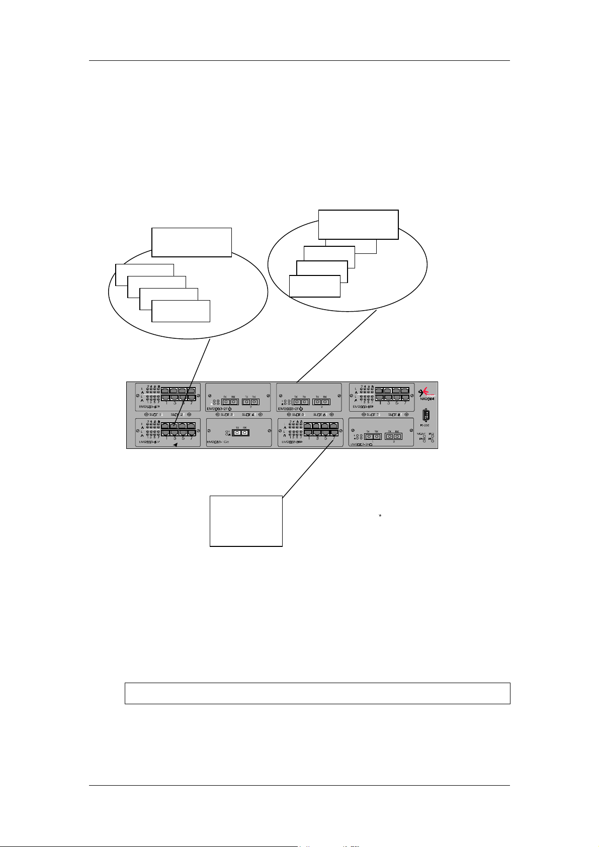
OptiSwitch-100/100F
Sample Configuration – VLAN/Server-port/Trunking
Port{xe "Virtual Networking:sample configuration"}
In the examples below, a new VLAN server is set to port 5.8 on VLAN tag number 30. The
PAYROLL VLAN (tag 10) is set to ports 1.1 to 1.4, and the FINANCE VLAN (TAg 20) is set
to ports 6.1 to 6.4. Both of them are given access to the server on port 7.
Physical Configuration Schema
Station 1
Station 2
Station 3
PAYROLL
Station 4
FINANCE
Station
Station
Station
Station
Application
server
Figure 7. Physical Configuration Schema
VLAN Server Port Configuration
An example of this is the following:
xe "VLAN sample:VLAN server port configuration"}
{
SYS_console>new-srvr-port run 7 30
Set VLAN Server Ports – OK
68
Page 76

OptiSwitch-100/100F
VLAN configuration{xe "VLAN sample:VLAN configuration"}
Payroll VLAN Configuration
An example of this is the following:
xe "VLAN sample:VLAN server port configuration"}
{
sys-console>new-vlan run FINANCE 1-2-3-4-7 10
Set run VLAN Domain entry – OK
Finance VLAN Configuration
An example of this is the following:
xe "VLAN sample:VLAN server port configuration"}
{
sys-console>new-vlan run PAYROLL 8-8-9-10-7 20
Set run VLAN Domain entry – OK
Checking the Configuration
An example of this is the following:
xe "VLAN sample:VLAN server port configuration"}
{
SYS_console>get-vlan-tbl run
Runtime VLAN mode is VLAN Tagging
VLAN Table from RUN database (Mgmt tag: 1)
RUNTIME VLAN TAG DOMAIN TABLE
===========================================
VID NAME TAG Ports
===========================================
1 S SRVR_30 30 1 2 3 4 22 23 24 25 7S
2 PAYROLL 20 6.01 6.02 6.03 6.04 7S
3 FINANCE 10 1 2 3 4 7S
69
Page 77

OptiSwitch-100/100F
Virtual Broadcast Domain
Virtual broadcasts domain{xe "Virtual broadcasts domain (VBC)"} is a concept that tends to
confine broadcasts in a physical domain, it allows to diminish the bandwidth used by
broadcasts, giving by the way more room to the unicast traffic, it also prevents the well known
phenomenon called broadcasts storms to affect the entire network. Of course VBC are not
made for a security purpose but to improve the efficiency of the communications in a network.
VBC disconnect entities belonging to different domain by avoiding the service traffic
(broadcasts) to go through. For instance, an ARP broadcast request sent by a machine which
belongs to VBC 1 to a machine belonging to VBC 2 will not have an answer, thus the
initiating entity cannot resolve the layer 3 address to a MAC address and consequently cannot
communicate with the VBC 2 machine.
VBC Mode{xe "VBC Mode"}
Viewing the VBC Mode{xe "VBC Mode:viewing VBC mode"}
get-vlan-mode
This command displays the current VBC mode.
get-vlan-mode {run|nvram}
get-vlan-mode shows vlan mode
opt.[arg #0] database type - either {run|nvram}; default : run
An example of this is the following:
SYS_console>get-vlan-mode run
Runtime VLAN mode is disabled
Setting the VBC Mode{xe "VBC Mode:setting VBC mode"}
set-vlan-mode
Three modes are available:
one mode can be defined for running session). The default mode is
set-vlan-mode <database><VLAN state>
set-vlan-mode set VBC or VLAN Tagging mode
opt.[arg #0] database type - either {run|nvram|all}; default : all
opt.[arg #1] VLAN state: either {vbc|tag|none}; default : tag
SYS_console>set-vlan-mode run vbc
Set run VLAN mode vbc- OK
vbc, tag
or
. The modes are mutually exclusive (i.e. only
none
none
.
Creating VBC Domains{xe "VBC Mode:creating VBC
domains"}
set-vbc-domain
This command establishes a Virtual broadcast domain.
ports to group into a broadcast domain.
70
port_list
is a dash-separated list of
Page 78

OptiSwitch-100/100F
set-vbc-domain {run|nvram|all} <port_list>
set-vbc-domain defines a Virtual Broadcast Domain
opt.[arg #0] database type - either {run|nvram|all}
opt.[arg #1] Virtual Broadcast Domain – ports list in format:
S1.D1 – Sn.Dn
An example of this is the following:
SYS_console>set-vbc-domain run 1-2-3-4
Set Runtime Virtual Broadcast Domain entry - OK
Runtime VLAN mode is VBC Domain
RUNTIME VIRTUAL BROADCAST DOMAIN TABLE
===========================================
Ports
11111111 7
VBC 12345678 1
1: ++++---- SYS_console>set-vbc-domain run 5-6-7
Set Runtime Virtual Broadcast Domain entry - OK
Runtime VLAN mode is VBC Domain
RUNTIME VIRTUAL BROADCAST DOMAIN TABLE
===========================================
Ports
11111111 7
VBC 12345678 1
1: ++++---- 2: ----+++- -
Viewing the VBC Table{xe "VBC Mode:viewing VBC table"}
get-vbc-tbl
This command displays the VBC table.
get-vbc-tbl {run|nvram}
get-vbc-tbl displays the Virtual Broadcast Domain Table
opt.[arg #0] database type - either {run|nvram}; default : run
An example of this is the following:
SYS_console>get-vbc-tbl run
Runtime VLAN mode is VBC Domain
RUNTIME VIRTUAL BROADCAST DOMAIN TABLE
===========================================
Ports
11111111 7
VBC 12345678 1
1: ++++---- 2: ----+++- -
71
Page 79

OptiSwitch-100/100F
Viewing the VBC Matrix{xe "VBC Mode:viewing VBC matrix"}
get-vbc-matrix
This command retrieves the current broadcast Domain matrix for a particular slot. The first
column is the source port list. The other columns are broadcast destination ports to which
frames from a given source port may be forwarded.
get-vbc-matrix <slot number>
get-vbc-matrix retrieves the VBC connectivity matrix
opt.[arg #0] column slot
SYS_console>get-vbc-matrix 1
VBC CONNECTIVITY MATRIX SLOT 1
================================
SRC to : 1 2 3 4 5 6 7 8
1 : - + + + - - - 2 : + - + + - - - 3 : + + - + - - - 4 : + + + - - - - 5 : - - - - - + + 6 : - - - - + - + 7 : - - - - + + - 8 : - - - - - - - 1 : - - - - - - - +
NOTE:
In this example the sign ‘+’ at the intersection of rows and columns means that a
connection is established. The sign ‘-’ indicates that there is no connectivity.
Deleting a VBC{xe "VBC Mode:deleting a VBC"}
del-vbc-domain
This command deletes a VBC domain,
by
get-vbc-tbl
.
where domain_id
del-vbc-domain {run|nvram} <domain_id>
del-vbc-domain deletes a Virtual Broadcast Domain
[arg.#0] database type - either {run|nvram}
[arg.#1] Virtual Broadcast Domain Id – decimal number as shown
in the <get-vbc-tbl> command
SYS_console>del-vbc-domain run 1
Delete Runtime Virtual Broadcast Domain entry - OK
Runtime VLAN mode is VBC Domain
RUNTIME VIRTUAL BROADCAST DOMAIN TABLE
===========================================
Ports
11111111 7
VBC 12345678 1
2: ----+++- -
NOTE:
When you use the set-vbc-domain command with the
runtime and nvram databases are changed. In case you need to delete the mentioned
vbc entries, you should run the del-vbc-domain command twice with run and nvram
parameters.
is the vbc id number as identified
all
parameter, both the
72
Page 80

OptiSwitch-100/100F
Utilities
Ping Commands{xe "Ping Commands"}{xe
"utilities:ping"}
Starting Ping{xe "Ping Commands:start ping"}
ping
The ping command is intended for testing the connectivity between the switch and other IP
network devices. It is not intended as a traffic generator. Thus, using the endless ping option is
not recommended.
Ping the IP address specified number of times or 0 for endless ping. The ping process starts
sending one datagram per second until the number of datagrams are sent. It prints one line of
output for each response that it receives. The ping command does not return any output if
there is no response. Normal response time is 1 to 10 seconds.
ping <IP address> {<number>|0}
This command modifies the VLAN priority
Ping IP traffic generator
[arg #0] destination IP address
[arg #1] number of packets to send or ) for endless ping
SYS_console>ping 194.90.136.20 4
SYS_console>194.90.136.20 Alive. echo reply: id 4643, seq 1, echo-data-len 0
194.90.136.20 Alive. echo reply: id 4643, seq 2, echo-data-len 0
194.90.136.20 Alive. echo reply: id 4643, seq 3, echo-data-len 0
194.90.136.20 Alive. echo reply: id 4643, seq 4, echo-data-len 0
PING process stopped - statistics :
ICMP echo requests : 4
ICMP echo responses : 4
PING process - press <CR> for prompt
SYS_console>
If a host does not respond, only statistics are printed. Failure to get an echo response from a
host may be due to:
A bad physical connection
•
A non-existent or inactive host
•
Network Unreachable: no corresponding entry in the routing table
•
Destination Unreachable: the default gateway failed to route the datagram
•
Outdated ARP table information - flush the ARP table with the
•
command.
del-arp-entry
73
Page 81

OptiSwitch-100/100F
Stopping Ping{xe "Ping Commands:stop ping"}
ping-stop
If you started a ‘long’ ping, use this command, or CTRL-C to stop the active ping process.
Port Mirroring{xe "utilities:port mirroring"}
The port mirroring feature allows you to copy frames from a selected port to a probe port for
diagnostic and troubleshooting purposes.
Port mirroring allows you to attach a network protocol analyzer to a probe port to view the
types of traffic passing through a particular switch port or ports.
This analysis can help troubleshoot network problems on a port-by-port basis.
Setup{xe "port mirroring:setup"}
Setting the Monitoring Port{xe "port mirroring:set monitoring port"}
set-mon-port
This command sets the monitoring port.
set-mon-port <slot> <port>
set-mon--port sets the monitoring port
[arg #0] port containing the monitoring device
The following is an example:
SYS_console>set-mon-port 1
Set of the Monitor Port - OK
Monitoring a Port{xe "port mirroring:monitoring a port"}
monitor
To set the port to be monitored and start the monitoring process decimal port. All traffic from
this port will be duplicated on the monitoring port specified by the set-mon-port
command.
monitor <slot>.<port number in slot>
monitor start port monitoring
[arg #0] port to be monitored
The following is an example:
SYS_console>monitor 4
Start monitoring port 4 - OK
NOTE: The monitoring device must be connected to the monitoring port before monitoring is
activated.
74
Page 82

OptiSwitch-100/100F
Saving the Configuration {xe "port mirroring:saving the configuration"}
save-mon
Stopping Monitoring{xe "port mirroring:stop monitoring"}
stop-mon
Viewing the NVRAM Configuration {xe "port mirroring:viewing NVRAM
configuration"}
get-nv-mon
This command saves the current port-monitoring configuration to the NVRAM.
SYS_console>save-mon
Save monitoring configuration to NVRAM - OK
Use this command to stop monitoring.
SYS_console>stop-mon
Stop monitoring - OK
Erasing the NVRAM Configuration{xe "port mirroring:erasing NVRAM
configuration"}
clear-nv-mon
Frame Generator{xe "Frame Generator"}
Setting the Frame Generator{xe "Frame Generator:setting"}
set-fg-param
This command retrieves the port monitoring information stored with the save-mon
command in the NVRAM.
SYS_console>get-nv-mon
The NVRAM based monitoring configuration is:
Monitored port: 4
Monitor port: 2
Monitor ACTIVE
Use this command to clear the NVRAM configuration.
SYS_console>clear-nv-mon
Clear NVRAM monitoring configuration - OK
This command sets the frame generator parameters.
hardware addresses in hex.
for the first 12 bytes.
set-fg-param <dest> <source> <fill_byte> <length>
set-fg-param sets the Ethernet frame
[arg #0] destination address in hex format xx xx xx xx xx xx
[arg #1] source address in hex format xx xx xx xx xx xx
[arg #2] frame fill pattern – hex byte
length
fill_byte
is the total length of the packet excluding CRC.
is a single byte used to fill the entire packet except
75
dest
and
source
are dash-separated
Page 83

OptiSwitch-100/100F
[arg #3] frame length – including DA, SA and type/length
76
Page 84

OptiSwitch-100/100F
An example of this is the following:
SYS_console>set-fg-param 00-0E-DE-02-80-01 00-0D-01-32-11-22 aa 100
Starting Frame Generation{xe "Frame Generator:starting"}
start-fg
This command starts frame generation.
generate traffic. For example, a
number in slot)
to be sent on each interface. A
specifies the number of packets per second to generate.
start-fg <slot> <port> <count> <rate>
start-fg starts the Ethernet frame generator
[arg #0] destination ports list in format: S1.D1-…-Sn.Dn
[arg #1] destination ports – ports list in format: S1.D1-…SnDn
[arg #2] frame per second
The following is an example:
SYS_console>start-fg 1-2 0 10
will send frames to specified ports.
dport
of 0 specifies an infinite number of packets.
count
is a dash-separated list of ports on which to
dport
range of S1.D1 – S2.D2
specifies the number of frames
count
(slot number.port
rate
Stopping Frame Generation{xe "Frame Generator:stopping"}
stop-fg
This command stops the Ethernet frame generator.
77
Page 85

OptiSwitch-100/100F
SNMP
This chapter explains how to use the Simple Network Management Protocol (SNMP){xe
"Simple Network Management Protocol (SNMP)"} to manage LAN Switch Processors. It
assumes that you are using an SNMP-based network management software application such as
MRV MegaVision ™ to manage the switches. Hereafter, this document refers to your network
management application as a Network Operations Center (NOC).
Additionally, this chapter describes the RMON (Remote Monitoring) application and the type
of network management applications that enable you to use RMON.
NB{xe "SNMP:NBase-Xyplex support"}ase-Xyplex
SNMP Support
SNMP is an Internet standard protocol, defined by the Internet Engineering Task Force (IETF)
Request for Comment (RFC) 1157, which specifies how network management information is
carried through a network. MRV switches support SNMP by implementing an SNMP agent.
The agent stores Management Information Base (MIB) data and makes it available when
requested via SNMP Set, Get, and Get_Next requests.
In addition, MRV switches generate SNMP Trap messages. Traps are notices that the switch
sends to an SNMP manager indicating that a specific event has occurred, or that the condition
of a unit has changed significantly.
SNMP Basic Configuration{xe "SNMP:basic
configuration"}
set-ip-cfg
To enable your NOC to communicate with a MRV switch, you must assign it an IP address.
Use the following command:
set-ip-cfg <ip-address> < ip-mask> < ip-broadcast>
set-ip-cfg set IP address, netmask and broadcast
[arg #0] IP address
[arg #1] netmask
[arg #2] broadcast
The address you assign must be valid for the network connected to the switch. In a routed
network, depending on the switch location, you also need to assign a subnet mask and
gateway, as follows:
set-gatew
To make sure that your NOC can exchange information with the switch, Ping the switch from
the NOC.
set-gatew <ip-gateway-address>
SNMP Community String Commands{xe "SNMP:community
string commands"}
-------------------------------------------------------------------
get-comm show current read or/and write community
set-comm change the read or write community
78
Page 86

OptiSwitch-100/100F
SNMP Community strings authenticate access to the MIB (Management Information Base).
Community strings function as passwords embedded in every SNMP packet. The community
string must match one of the two community strings configured in the switch for the message
to be processed. There are two community strings, one for each of the following types of
accesses:
• read
• write
- mode gives read access to all the objects in the MIB, but does not allow write access
- mode gives write access to all objects in the MIB
Viewing the Community String{xe "SNMP Community String:viewing"}
get-comm
This command displays the SNMP community string for a given access mode (read or write).
If the access mode is specified as *, both the read and the write community strings are
displayed.
get-comm {read|write|*}
get-comm show current read or/and write community
[arg #0] either {read|write|*}
An example of this is the following:
SYS_console> get-comm *
Current read community is: < public >
Current write community is: < private >
Setting the Read or Write Community{xe "SNMP Community
String:setting read or write"}
set-comm
This command lets you specify the SNMP community string for each of the two access
modes: read and write.
set-comm {read|write} <community-string>
set-comm change the read and write community
[arg #0] either {read|write}
[arg #1] new comm
An example of this is the following:
SYS_console>set-comm write password
New write community is: < password >
SYS_console>
79
Page 87

OptiSwitch-100/100F
SNMP Traps{xe "SNMP Traps"}
Traps are notices that the switch sends to an SNMP manager indicating a specific event has
occurred, or the condition of a unit has changed significantly. SNMP Traps are disabled
default.
NOTE: Trap messages do not provide an entirely reliable event notification mechanism; they
can get dropped, and are not acknowledged or retransmitted once dropped.
When the Switch detects an extraordinary event, it generates a trap. A trap is a notification
message that may be sent to predefine Network Management Stations. A trap event may be a
reset (cold or warm), detection of an interface link status change, an SNMP authentication
failure due to an incorrect community string, etc.
The SNMP trap commands let you manage whether or not the device issues an authentication
trap to the list of selected SNMP Management Stations. The list has a maximum of five
entries.
get-auth shows the traps authentication mode
set-auth modifies the traps authentication mode
get-traps show destination stations in the trap list
add-trap add a destination station to the trap list
del-trap delete a destination station from the trap list
by
Setting Authentication Traps{xe "SNMP Traps:setting
authentication traps"}
The Authentication Failures trap is generated whenever a login attempt fails during the
authentication process on a management port.
Viewing the Authentication Trap Status {xe "SNMP Traps:viewing
authentication trap status"}
get-auth
This command displays the authentication trap messages.
SYS_console>get-auth
The authentication trap messages are enabled
80
Page 88

OptiSwitch-100/100F
Enabling/Disabling the Authentication Trap{xe "SNMP
Traps:enabling/disabling traps"}
set-auth
This command enables or disables the authentication trap.
set-auth {enable|disable}
set-auth modifies the authentication mode
[arg #0] traps auth mode: either {enable
[arg #1] new comm
An example of this is the following:
SYS_console>set-auth disable
The authentication trap message mode change OK
The authentication trap messages are DISABLED
Configuring the Trap Stations{xe "SNMP Traps:configure
trap stations"}
Viewing the Stations List {xe "SNMP Traps:viewing stations list"}
get-traps
This command displays the Stations list.
SYS_console>get-traps
SNMP TRAP TABLE
===============
IPADDR COMMUNITY
---------------------------------------------------
194.090.136.126 ----------- public
Adding a Station to the List{xe "SNMP Traps:add station to the list"}
add-trap
The
add-trap
trap community string that appears in the trap message.
add-trap <IP address> <trap-community>
add-trap add a destination station to the trap list
[arg #0] IP address
[arg #1] community
The following is an example:
SYS_console>add-trap 194.90.136.20 rnd
Entry 194.90.136.20 - rnd added
SNMP TRAP TABLE
===============
IPADDR COMMUNITY
---------------------------------------------------
194.090.136.126 ----------- public
194.090.136.020 ----------- rnd
---------------------------------------------------
command enters the IP Address of the SNMP Management Station and the
81
Page 89

OptiSwitch-100/100F
82
Page 90

list"}
OptiSwitch-100/100F
Deleting a Station From the List{xe "SNMP Traps:delete station from
del-trap
The station’s
command.
del-trap <IP address>
del-trap delete a destination station to the trap list
[arg #0] IP address
The following is an example:
SYS_console>del-trap 194.90.136.20
Entry 194.90.136.20 - deleted
IP address
must be given as shown in the list provided with
get-trap
83
Page 91

OptiSwitch-100/100F
Statistics
This chapter contains instructions for displaying the switching statistics{xe "switching
statistics"}. Type
provide full physical layer information as well as inter-port switching statistics.
sys_console> statistics
Switching Statistics related commands
---------------------------------------------------------------------
clr-cnt clears the switch counters: ethernet and
bridging
get-eth-cnt gets the ethernet counters per port
get-colls-cnt gets the collision distribution counters per
port
get-rmon-cnt gets the ethernet RMON counters per port
get-sdist-cnt gets packet size distribution counters per port
get-mgm-brcnt gets the switching counters of the mgmt port
sys_console>
statistics
to view all the related commands. The commands below
Clearing the Switch Counters {xe "switching
statistics:clear switch counters"}
clr-cnt
This command clears the Ethernet and bridging counters.
Viewing Statistics on a Particular Port{xe "switching
statistics:view port statistics"}
get-eth-cnt
This command displays port statistics.
get-eth-cnt.<port-number>
get-eth-cnt gets the Ethernet counters per port
[arg #0] port index.<port-numberin slot>
The following is an example:
SYS_console> get-eth-cnt 2
Ethernet Statistics for port 2
===================================================
Good Bytes Received : 0
Good Bytes Sent : 0
Good Frames Receive : 0
Good Multicast Frames Receive : 0
Good BroadCast Frames Receive : 0
Frames Sent : 0
Multicast Frames Sent : 0
BroadCastFrames Sent : 0
Receive and Transmit Collisions : 0
Receive and Transmit Late Collisions : 0
Receive CRC or Alignment Error : 0
Receive Frame > 1518 bytes with Bad CRC : 0
84
Page 92

OptiSwitch-100/100F
Receive Fragments : 0
Receive Frame > 1518 bytes with Good CRC : 0
===================================================
Getting Collisions on a Port{xe "switching
statistics:getting port collisions"}
get-colls-cnt
This command displays the port collision count.
get-colls-cnt.<port-number>
get-colls-cnt gets the collision distribution counters per port
[arg #0] port index in format.<port-number>
The following is an example:
SYS_console>get-colls-cnt 2
Ethernet Collision Counters for port 2
==========================================
Collision Count : 0
Single Collision Count : 0
Multiple Collision Count : 0
Excessive Collision Count : 0
Late Collision Count : 0
==========================================
Rmon Statistics{xe "Rmon Statistics"}
Viewing Rmon Statistics Group for a Port{xe "Rmon Statistics:viewing
RMON group statistics for port"}
get-rmon-cnt
This command displays a port’s RMON Statistics Group.
get-rmon-cnt.<port number>
get-rmon-cnt
[arg #0] port index.<port-number>
The following is an example:
SYS_console>get-rmon-cnt 3
Ethernet RMON Counters for port 3
====================================================
etherStatsOctets : 0
etherStatsPkts : 0
etherStatsBcastPkts : 0
etherStatsMcastPkts : 0
etherStatsCRCAllignPkts: 0
etherStatsUndersizePkts: 0
etherStatsOversizePkts : 0
etherStatsRuntPkts : 0
etherStatsJabberPkts : 0
etherStatsCollisions : 0
gets the Ethernet RMON counters per port
85
Page 93

OptiSwitch-100/100F
Getting the Packet Size Distribution{xe "Rmon Statistics:getting packet
size distribution"}
get-sdist-cnt
This command is available for Fast Ethernet ports only.
get-sdist-cnt
[arg #0] port index.<port-number>
The following is an example:
SYS_console>get-sdist-cnt 3
RMON Packet Size Distribution Counters for port 3
============================================================
etherStatsPkts64Octets : 0
etherStatsPkts65to127Octets : 0
etherStatsPkts128to255Octets : 0
etherStatsPkts256to511Octets : 0
etherStatsPkts512to1023Octets : 0
etherStatsPkts1024to1518Octets : 189307821
get-sdist-cnt.<port number>
gets packet size distribution counters per port
Viewing the Management Counters
get-mgm-brcnt
This command displays the Management counters.
An example of this is the following:
xe "Rmon Statistics:viewing management counters"}
{
SYS_console>get-mgm-brcnt
Management Port Counters
=============================================
Frm Received : 129079
Bytes Received : 13451284
Frm Received Ucast: 6762
Frm Received Bcast: 96087
Frm Received Mcast: 26230
Frm Transmited : 287975
Bytes Transmited : 18921661
Frm Transmit Ucast: 6659
Frm Transmit Bcast: 295
Frm Transmit Mcast: 281021
------------------------------------------------------ port : Received frames : Transmited frames :
number: UCAST : BCAST : MCAST : UCAST : BCAST : MCAST :
1 0 0 0 0 0 0
2 0 0 0 0 0 0
3 0 0 0 0 0 0
4 0 0 0 0 0 0
5 0 0 0 0 0 0
6 0 0 0 0 0 0
7 6541 90338 24160 6454 293 34
8 0 0 0 0 0 0
9 0 0 0 0 0 0
10 0 0 0 0 0 0
11 0 0 0 0 0 0
12 0 0 0 0 0 0
13 0 0 0 0 0 0
14 0 0 0 0 0 0
15 0 0 0 0 0 0
16 0 0 0 0 0 0
86
Page 94

OptiSwitch-100/100F
17 0 0 0 0 0 0
18 0 0 0 0 0 0
19 0 0 0 0 0 0
20 0 0 0 0 0 0
21 0 0 0 0 0 0
22 0 166 113 80 2 763
23 279 5901 2045 262 2 64
87
Page 95

OptiSwitch-100/100F
Troubleshooting
The OptiSwitch-100/F is a highly reliable unit. If you encounter an operating problem, follow
the troubleshooting{xe "troubleshooting"} steps below. If the problem persists, contact your
local MRV representative.
1. Ensure that the unit is plugged into a grounded, functioning AC outlet providing between 90 VAC
and 264 VAC at 50/60 Hz. Check the power fuse and replace if blown.
CAUTION
For continued fire protection, replace with fuses of the same type and rating.
2. Review all link LEDs to ensure that those ports you believe should be functioning are properly
attached to a cable.
3. Verify that your cables are wired correctly. (See
Problem:
Cause:
Solution:
4. Review all link LEDs to ensure that those ports you believe should be functioning are properly
configured, and not disabled or partitioned.
Problem:
Cause:
Solution:
5. Ensure that the equipment attached to the switch is properly configured.
If you encounter any situations or problems you cannot solve, obtain, if possible, the following
information:
The serial number of your switch and its hardware address
•
LINK LED is ON but data is not being forwarded through
switch.
Cables are too long.
Make sure that cables are as defined in the installation
section of this guide. Check that cables meet the 10BaseT/100Base-TX standards and that they do not exceed 100m.
Port disabled due to a defective device on segment.
When a defective NIC card causes a permanent jam on the
network, the port will be disabled by the OptiSwitch-100/F.
a) Locate the defective device and disconnect it from the
network.
b) The disabled port can be enabled through management or
by shutting off the unit and powering up again.
Network Connections)
If the NMS option is installed, the firmware revision number displayed in the terminal
•
console banner message.
The configuration of the equipment being interfaced with the switch.
•
The sequence of events leading up to your problem.
•
Troubleshooting procedures you have already followed.
•
After compiling the above information, contact your local MRV representative or a Customer
Service{xe "Customer Service Phone Numbers"} Representative. In addition, if you have
specific questions about your network configuration, or have a particularly difficult network,
please call our technical support.
Contacts
USA
International
1-818-773-0900
972-4-993-6200
[email protected]
www.opticalaccess.com
88
Page 96

OptiSwitch-100/100F
Appendix A: Console Command Line Quick Reference
Commands Groups
console
system
ip
snmp
switch-db
vlan
echannel
mac-security
port-cfg
statistics
sp-tree
Console related commands
System related commands
IP related commands
SNMP related commands
Switching Database related commands
Virtual LANS related commands
EtherChannel Commands
MAC security related commands
Port Configuration related commands
Switching Statistics related commands
Spanning Tree related commands
Console Commands{xe "Command Line Quick
Reference:console commands"}
help-kbd
banner
clear
login
logout
set-page
set-prompt
set-attr-prompt
set-attr-msg
set-attr-text
set-passwd
Lists the console functional keys.
Displays banner.
Clears the screen (no argument is required with this
command).
Exits Admin Interface; but does not disconnect a Telnet
session.
Exits Admin Interface; Telnet session will be disconnected.
Sets console page.
Changes console prompt.
Sets the prompt attributes.
Sets the message attributes.
Sets the text attributes.
Changes the console password.
89
Page 97

OptiSwitch-100/100F
System Commands{xe "Command Line Quick
Reference:system commands"}
sys-stat
get-stst-level
set-stst-level
warm-reset
cold-reset
get-last-err
init-nvram
get-sw-file
set-sw-file
get-tftp-mode
set-tftp-mode
get-tftp-srvr
set-tftp-srvr
sw-dnld
set-fg-param
start-fg
stop-fg
Shows system status.
Shows the hardware selftest level.
Changes the hardware selftest level.
Restarts the device without resetting the log.
Restarts the device the same way as a power cycle.
Retrieves the number of warm resets since the last hardware
reset. It also displays the last Fatal error message and the
time since that error happened.
Resets the non-volatile RAM on the SNMP Agent to default
values.
Retrieves SNMP agent software file name.
Sets the SNMP Agent Software file name - for download.
Retrieves the TFTP download mode.
Sets the TFTP download mode.
Retrieves the TFTP server address.
Sets the TFTP server IP address.
Begins software download from TFTP server.
Sets the Ethernet frame generator parameters.
Starts the Ethernet frame generator
Stops the frame generator.
IP Commands{xe "Command Line Quick Reference:IP
commands"}
get-ip
set-ip
get-ip-cfg
set-ip-cfg
clear-ip-cfg
get-gatew
set-gatew
get-bootp
stop-fg
Shows current IP address.
Sets IP address.
Shows current IP configuration.
Sets IP address, netmask and broadcast.
Clears IP configuration in NVRAM.
Shows default gateway.
Defines default gateway.
starts the Ethernet frame generator
stops the Ethernet frame generator
Ping Commands{xe "Command Line Quick Reference:ping
commands"}
ping
ICMP utility.
90
Page 98

OptiSwitch-100/100F
ping-stop
Stops the ping process.
91
Page 99

OptiSwitch-100/100F
Address Resolution Protocol{xe "Command Line Quick
Reference:ARP commands"}
get-arp-tbl
del-arp-entry
add-arp-entry
get-arp-stats
Displays the ARP Table.
Deletes an entry/all entries (*) of the ARP table.
Adds an entry to the ARP table.
Gets ARP statistics.
SNMP{xe "Command Line Quick Reference:SNMP
commands"}
get-comm
set-comm
get-auth
set-auth
get-traps
add-trap
del-trap
Shows current read and /or write community.
Changes the read or write community.
Shows the traps authentication mode.
Sets the trap authentication mode.
Shows destination stations in the trap list.
Adds destination station to trap list.
Deletes a destination station from trap list.
Switching{xe "Command Line Quick Reference:switching
database commands"}
get-lt-entry
get-lt-16
find-lt-addr
del-lt-entry
del-lt-port
del-lt-addr
add-lt-entry
get-lt-age
set-lt-age
Gets a Learning Table entry at index.
Gets 16 Learning Table entries starting at a given index.
Searches for an address in the Learning Table.
Removes a Learning Table entry at index.
Deletes the Learning Table entries for a port.
Removes a Learning Table with a given address.
Adds a Learning Table entry.
Displays the Learning Table aging period.
Modifies the Learning Table aging period.
92
Page 100

OptiSwitch-100/100F
Virtual Networking{xe "Command Line Quick Reference:virtual
LAN commands"}
get-vlan-matrix
set-vbc-domain
del-vbc-domain
get-vbc-tbl
get-vbc-matrix
get-vlan-tbl
get-vlan-entry
new-vlan
del-vlan
vlan-name-modify
vlan-tag-modify
vlan-ports-modify
vlan-prio-modify
set-vlan-mode
get-vlan-mode
set-mgmt-vlan
get-mgmt-vlan-tag
del-mgmt-from-vlan
add-mgmt-to-vlan
new-srvr-port
del-srvr-port
set-mon-port
monitor
stop-mon
get-nv-mon
save-mon
clear-nv-mon
set-priority-policy
get-priority-policy
retrieves the TAG VLAN connectivity matrix
defines a Virtual Broadcast Domain
deletes a Virtual Broadcast Domain
displays the Virtual Broadcast Domain Table
retrieves the VBC connectivity matrix
Display VLAN Table
Display VLAN entry
Make a new VLAN
Delete a VLAN
Modifies the Name of a VLAN
Modifies the VLAN tag
Modifies the VLAN Ports
Modifies the VLAN priority
Set VBC or VLAN Tagging mode
Shows VLAN mode
Set Management VLAN
Get Management VLAN tag
Returns the Management VLAN tag to default value (1)
Adds Management to existing VLAN
Set a Vlan Server port(s)
Del a Vlan Server Port(s)
sets the monitoring port
starts port monitoring
stops port monitoring
retrieves the NVRAM based monitoring configuration
saves the running monitoring configuration to NVRAM
clears the NVRAM based monitoring configuration
Set a policy for switch priority
Get a policy for switch priority
93
 Loading...