


MR2228-S2C
Stackable Fast Ethernet Switch
Installation Guide
Installation GMMMMMM

Installation Guide
Stackable Fast Ethernet Switch
with 24 10BASE-T/100BASE-TX (RJ-45) Ports,2 1000BASE-T Combination Ports
(RJ-45/SFP),and 2 1000BASE-T/Stacking Ports
MR2228-S2C
2

Contents
Chapter 1: Introduction............................................................................................................1
Overview..........................................................................................................................1
Switch Architecture...................................................................................................1
Network Management Options .................................................................................2
Description of Hardware ..................................................................................................2
10BASE-T/100BASE-TX Ports .................................................................................2
1000BASE-T/SFP Ports............................................................................................2
Stacking Ports...........................................................................................................3
Port and System Status LEDs ..................................................................................3
Power Supply Receptacles.......................................................................................5
Features and Benefits......................................................................................................6
Connectivity .............................................................................................................. 6
Expandability ............................................................................................................6
Performance .............................................................................................................6
Management.............................................................................................................7
Chapter 2: Network Planning ..................................................................................................8
Introduction to Switching..................................................................................................8
Application Examples....................................................................................................... 8
Collapsed Backbone.................................................................................................8
Network Aggregation Plan ........................................................................................ 9
Remote Connections with Fiber Cable ...................................................................10
Making VLAN Connections..................................................................................... 11
Application Notes ........................................................................................................... 12
Chapter 3: Installing the Switch............................................................................................. 13
Selecting a Site..............................................................................................................13
Ethernet Cabling ............................................................................................................13
Equipment Checklist ......................................................................................................14
Package Contents ..................................................................................................14
Optional Rack-Mounting Equipment .......................................................................14
Mounting ........................................................................................................................ 14
Rack Mounting........................................................................................................15
Desktop or Shelf Mounting......................................................................................16
Installing an Optional SFP Transceiver..........................................................................17
Connecting Switches in a Stack..................................................................................... 17
Connecting to a Power Source ......................................................................................18
Connecting to the Console Port ..................................................................................... 19
Wiring Map for Serial Cable....................................................................................19
Chapter 4: Making Network Connections..............................................................................21
Connecting Network Devices.........................................................................................21
Twisted-Pair Devices .....................................................................................................21
Cabling Guidelines.................................................................................................. 21
Connecting to PCs, Servers, Hubs and Switches...................................................21
Network Wiring Connections...................................................................................22
Fiber Optic SFP Devices................................................................................................ 23
Connectivity Rules ......................................................................................................... 24
1000BASE-T Cable Requirements ......................................................................... 24
1000 Mbps Gigabit Ethernet Collision Domain .......................................................25
100 Mbps Fast Ethernet Collision Domain.............................................................. 25
10 Mbps Ethernet Collision Domain........................................................................ 25
Cable Labeling and Connection Records....................................................................... 25
Appendix A: Troubleshooting ................................................................................................ 27
Diagnosing Switch Indicators.........................................................................................27
1

Power and Cooling Problems ........................................................................................27
Installation...................................................................................................................... 28
In-Band Access..............................................................................................................28
Stack Troubleshooting ................................................................................................... 28
Appendix B: Cables...............................................................................................................29
Twisted-Pair Cable and Pin Assignments ...................................................................... 29
10BASE-T/100BASE-TX Pin Assignments.............................................................29
Straight-Through Wiring.......................................................................................... 30
Crossover Wiring ....................................................................................................30
1000BASE-T Pin Assignments ...............................................................................31
Fiber Standards .............................................................................................................32
2
Chapter 1: Introduction
Overview
The MR2228-S2C switch is a stackable Fast Ethernet switch with 24
10BASE-T/100BASE-TX ports and two 1000BASE-T ports that operate in
combination with two Small Form Factor Pluggable (SFP) transceiver slots. The
switch also provides two 1 Gbps built-in stacking ports for connecting up to eight
units in one stack. The stacking ports can also be used as normal Ethernet ports
in standalone mode. The MR2228-S2C also includes an SNMP-based
management agent, which provides both in-band and out-of-band access for
managing the switch.
The MR2228-S2C provides a broad range of powerful features for Layer 2
switching, delivering reliability and consistent performance for your network traffic.
It brings order to poorly performing networks by segregating them into separate
broadcast domains with IEEE 802.3Q compliant VLANs, and empowers
multimedia applications with multicast switching and CoS services.
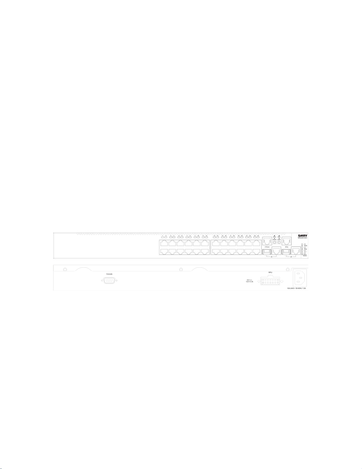
Figure 1-1. Front and Rear Panels
Switch Architecture
The MR2228-S2C employs a wire-speed, non-blocking switching fabric. This
permits simultaneous wire-speed transport of multiple packets at low latency on
all ports. The switch also features full-duplex capability on all ports, which
effectively doubles the bandwidth of each connection.
The switch uses store-and-forward switching to ensure maximum data integrity.
With store-and-forward switching, the entire packet must be received into a buffer
and checked for validity before being forwarded. This prevents errors from being
propagated throughout the network.
The switch includes built-in stacking ports that enable up to eight units that can
be connected together through a 1 Gbps stack backplane. The switch stack can
be managed from a master unit using a single IP address.
1

Network Management Options
With a comprehensive arrangment of LEDs, the MR2228-S2C provides “at a
glance” monitoring of network and port status. The switch can be managed over
the network with a web browser or Telnet application, or via a direct connection to
the console port. The switch includes a built-in network management agent that
allows it to be managed in-band using SNMP or RMON (Groups 1, 2, 3, 9)
protocols. It also has an RS-232 serial port (DB-9 connector) on the front panel for
out-of-band management. A PC may be connected to this port for configuration
and monitoring out-of-band via a null-modem serial cable. (See Appendix B for
wiring options.)
For a detailed description of the advanced features, refer to the Management
Guide.
Description of Hardware
10BASE-T/100BASE-TX Ports
The MR2228-S2C base unit contains 24 10BASE-T/100BASE-TX RJ-45 ports. All
ports support automatic MDI/MDI-X operation, so you can use straight-through
cables for all network connections to PCs or servers, or to other switches or
hubs.(See “10BASE-T/100BASE-TX Pin Assignments” on page B-1.)
Each of these ports support auto-negotiation, so the optimum transmission mode
(half or full duplex), and data rate (10, or 100 Mbps) can be selected automatically.
If a device connected to one of these ports does not support auto-negotiation, the
communication mode of that port can be configured manually.
Each port also supports IEEE 802.3x auto-negotiation of flow control, so the
switch can automatically prevent port buffers from becoming saturated.
1000BASE-T/SFP Ports
These are combination Gigabit RJ-45 ports with shared Small Form Factor
Pluggable (SFP) transceiver slots. If an SFP transceiver (purchased separately) is
installed in a slot and has a valid link on the port, the associated RJ-45 port is
disabled.
The 1000BASE-T RJ-45 ports support automatic MDI/MDI-X operation, so you
can use straight-through cables for all network connections to PCs or servers, or
to other switches or hubs. (See “1000BASE-T Pin Assignments” on page B-3.)
2
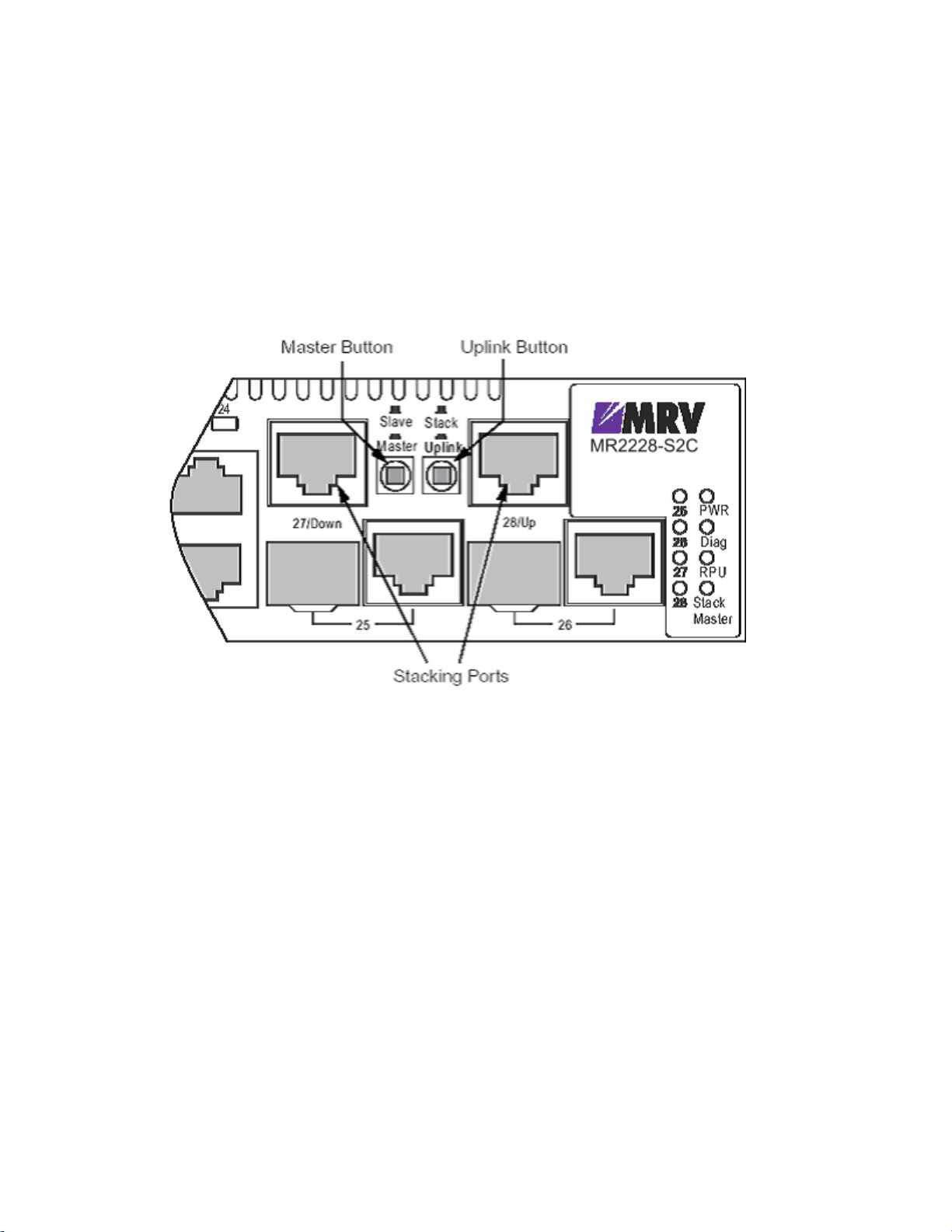
Stacking Ports
The unit provides two stacking ports that provide a 1 Gbps stack backplane
connection. Up to eight switches can be connected together using Category 5
Ethernet cables (purchased separately). The Master button enables one switch in
the stack to be selected as the master. This is the unit through which you manage
the entire stack.
The stacking ports can also be used as normal Ethernet ports in standalone mode
by pressing the Uplink button.
Figure 1-2. Stacking Ports
Port and System Status LEDs
The MR2228-S2C base unit includes a display panel for key system and port
indications that simplify installation and network troubleshooting. The LEDs, which
are located on the front panel for easy viewing, are shown below and described in
the following tables.
3
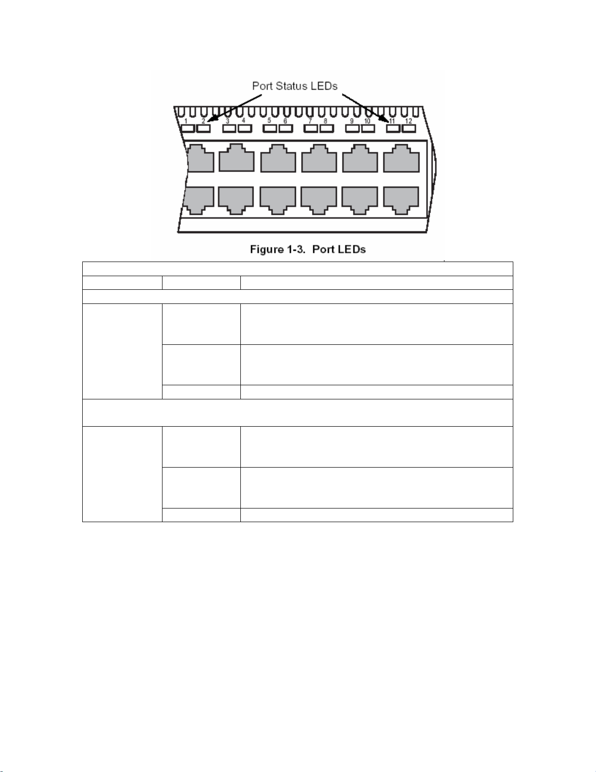
Table 1-1. Port Status LEDs
LED Condition Status
Fast Ethernet Ports (Ports 1-24)
(Link/Activity)
On/Flashing
Amber
Port has established a valid 10 Mbps network
connection.
Flashing indicates activity.
On/Flashing
Green
Port has established a valid 100 Mbps network
connection.
Flashing indicates activity.
Off There is no valid link on the port.
Gigabit Ethernet Ports (Ports 25-26 and Ports 27-28 when stacking is not
implemented)
(Link/Activity)
On/Flashing
Amber
Port has established a valid 10/100 Mbps network
connection.
Flashing indicates activity.
On/Flashing
Green
Port has established a valid 1000 Mbps network
connection
Flashing indicates activity.
Off There is no valid link on the port.
4
Table 1-2. System Status LEDs
LED Condition Status
PWR
Diag
RPU
Stack
On Green The unit’s internal power supply is operating
normally.
On Amber The unit’s internal power supply has failed.
Off The unit has no power connected.
On Green The system diagnostic test has completed
successfully.
Flashing
Green
On Amber The system diagnostic test has detected a fault.
Green A redundant power unit is attached and is in backup
Amber There is a fault in the redundant power unit.
Off There is no redundant power unit currently
Flashing
Amber
Green This switch is acting as the Master unit in the stack.
Amber This switch is acting as a Slave unit in the stack.
Flashing
Green
The system diagnostic test is in progress.
or active mode.
attached.
An initial power-on state during which the stack
configuration is detected.
When the user enters the light unit command in
the CLI, the unit ID of each switch in the stack will
be displayed by the port LEDs 1 to 8.
Power Supply Receptacles
There are two power receptacles on the rear panel of the switch. The standard
5
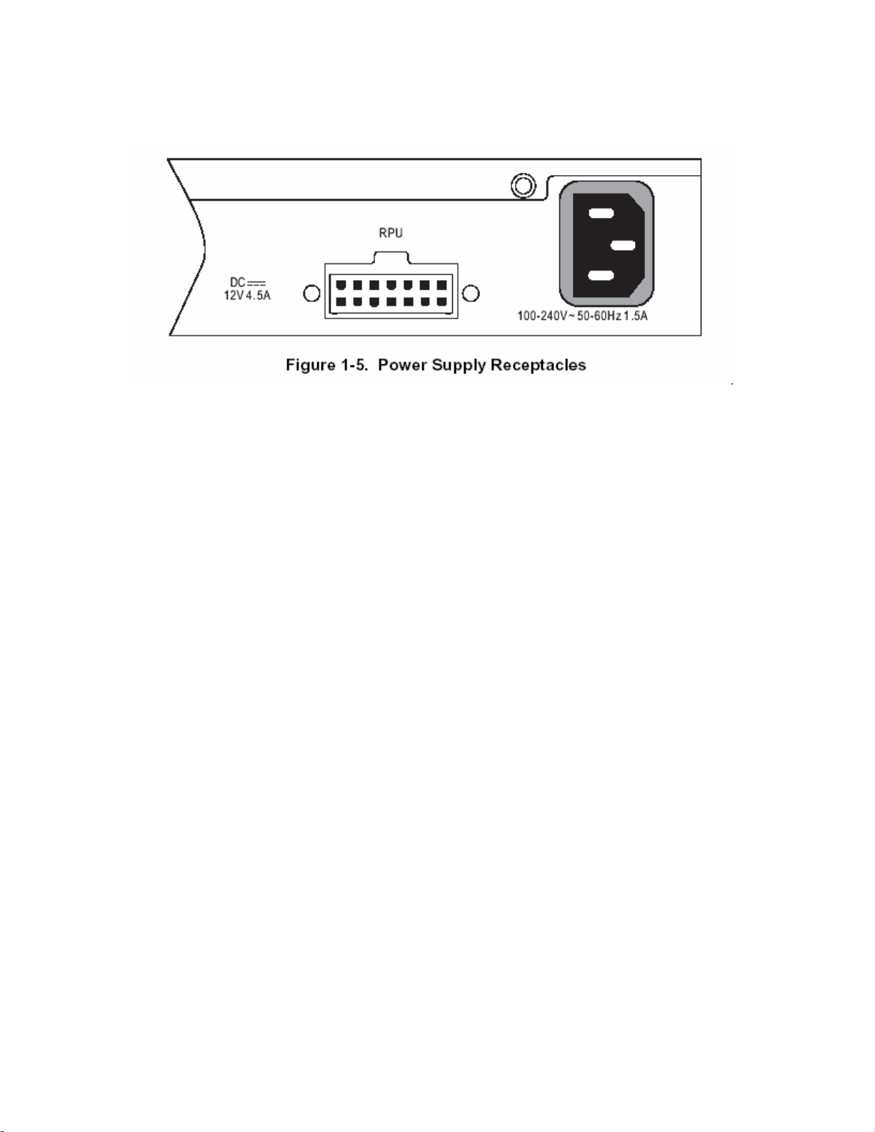
power receptacle is for the AC power cord. The receptacle labeled “RPU” is for
the optional Redundant Power Unit (RPU).
Features and Benefits
Connectivity
• 24 dual-speed ports for easy Fast Ethernet integration and for protection of your
investment in legacy LAN equipment.
• Auto-negotiation enables each RJ-45 port to automatically select the optimum
communication mode (half or full duplex) if this feature is supported by the
attached device; otherwise the port can be configured manually.
• Independent RJ-45 10/100BASE-TX ports with auto MDI/MDI-X.
• Unshielded (UTP) cable supported on all RJ-45 ports: Category 3 or better for 10
Mbps connections, Category 5 or better for 100 Mbps connections, and Category
5, 5e or 6 for 1000 Mbps connections.
• IEEE 802.3 Ethernet, 802.3u Fast Ethernet, and 802.3z and 802.3ab Gigabit
Ethernet compliance ensures compatibility with standards-based hubs, network
cards and switches from any vendor.
• Provides stacking capability via RJ-45 ports with 1 Gbps stacking bandwidth. Up
to 8 units can be stacked together.
Expandability
• Supports 1000BASE-SX, 1000BASE-LX and 1000BASE-LH SFP transceivers.
Performance
• Transparent bridging
• Aggregate duplex bandwidth of up to 8.8 Gbps
6

• Switching table with a total of 8K MAC address entries
• Provides store-and-forward switching
• Wire-speed filtering and forwarding
• Supports flow control, using back pressure for half duplex and IEEE 802.3x for
full duplex
• Broadcast storm control
Management
• “At-a-glance” LEDs for easy troubleshooting
• Network management agent:
• Manages switch in-band or out-of-band
• Supports Telnet, SNMP/RMON and web-based interface
7

Chapter 2: Network Planning
Introduction to Switching
A network switch allows simultaneous transmission of multiple packets via
non-crossbar switching. This means that it can partition a network more efficiently
than bridges or routers. The switch has, therefore, been recognized as one of the
most important building blocks for today’s networking technology.
When performance bottlenecks are caused by congestion at the network access
point (such as the network card for a high-volume file server), the device
experiencing congestion (server, power user, or hub) can be attached directly to a
switched port. And, by using full-duplex mode, the bandwidth of the dedicated
segment can be doubled to maximize throughput.
When networks are based on repeater (hub) technology, the maximum distance
between end stations is limited. For Ethernet, there may be up to four hubs
between any pair of stations; for Fast Ethernet, the maximum is two. This is
known as the hop count. However, a switch turns the hop count back to zero. So
subdividing the network into smaller and more manageable segments, and linking
them to the larger network by means of a switch, removes this limitation. A switch
can be easily configured in any Ethernet, Fast Ethernet, or Gigabit Ethernet
network to significantly boost bandwidth while using conventional cabling and
network cards.
Application Examples
The MR2228-S2C is not only designed to segment your network, but also to
provide a wide range of options in setting up network connections. Some typical
applications are described below.
Collapsed Backbone
The MR2228-S2C is an excellent choice for mixed Ethernet and Fast Ethernet
installations where significant growth is expected in the near future. You can
easily build on this basic configuration, adding direct full-duplex connections to
workstations or servers. When the time comes for further expansion, just connect
to another hub or switch using one of the Fast Ethernet or Gigabit Ethernet ports
built into the front panel, or using a Gigabit Ethernet port on a plug-in SFP
8
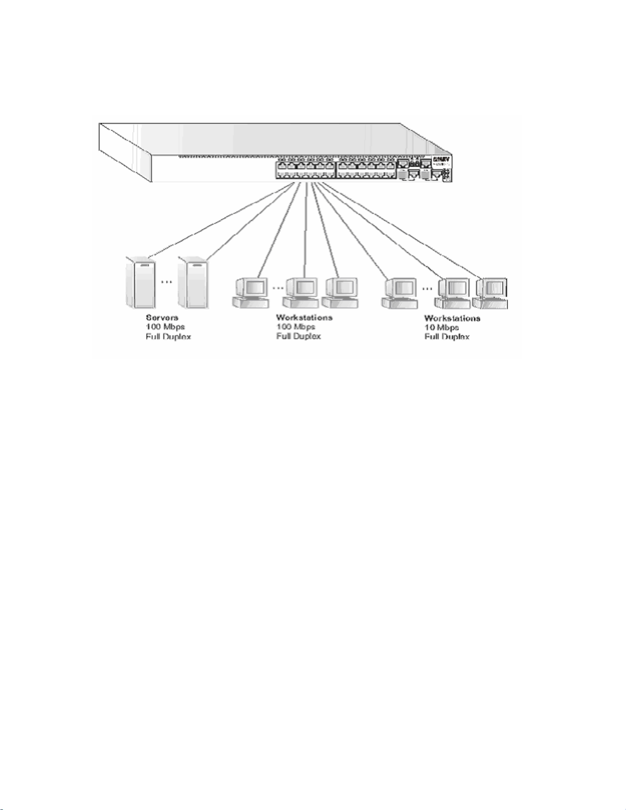
transceiver. In the figure below, the switch is operating as a collapsed backbone
for a small LAN.It is providing dedicated 10 Mbps full-duplex connections to
workstations and 100 Mbps full-duplex connections to power users and servers.
Figure 2-1. Collapsed Backbone
Network Aggregation Plan
With 28 parallel bridging ports (i.e., 28 distinct collision domains), the
MR2228-S2C can collapse a complex network down into a single efficient bridged
node, increasing overall bandwidth and throughput.
When up to eight switch units are stacked together, they form a single “virtual”
switch containing up to 208 ports. The whole stack can be managed through the
Master unit using a single IP address. In the figure below, the
10BASE-T/100BASE-TX ports on the switch are providing 100 Mbps connectivity
for up to 24 segments. In addition, the switch is also connecting several servers at
1000 Mbps.
9
 Loading...