

Page 1
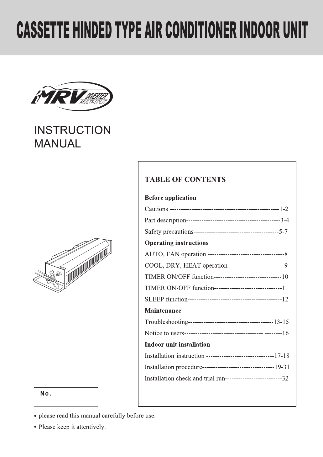
Household MRV
Ceiling Concealed Type Room Air Conditioner
AE092FCAHA
AE182FCAHA
0010570925
A
Page 2
123
Page 3
Page 4

AE092FCAHA
AE182FCAHA
Page 5
Part description
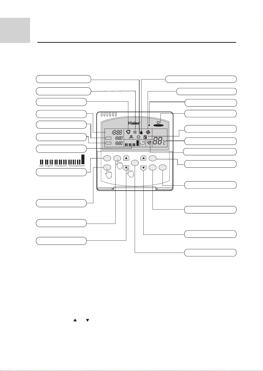
Remote controller
Heating operation indication
Cooling operation indication
Automatic operation
Clock display
TIMER ON display
TIMER OFF display
Fan speed display
L L M L M H L M H
AUTO
TIMER key
For selecting timer mode:
TIMER ON
TIMER OFF
TIMER ON/OFF
SET key
For setting the clock and time
for timer operation.
CLOCK key
For checking the clock time.
HOUR step key
For adjusting the clock and
time for timer operation.
TIMER ON
TIMER OFF
TIMER
SET
Dehumidifying operation indication
Fan only operation indication
Operation indicator
Power ON/OFF key
R
AM
PM
AM
PM
AM
PM
LOW MIN HIGH
AUTO
ROOM TEMP
SET TEMP
ion
Used to turn on /off the machine.
Sleep status indication
Temperature display
Automatic louver indication
CLOCK
3
SLEEP
TIME
1
2
TEMP
SWING
FAN
SPEED
MODE
LOU key
Used to select an automatic
or fixed air supplying direction.
MODE key
Used to select operation mode:
AUTO, COOL, DRY, HEAT, FAN.
FAN SPEED key
Used to select fan speed:
LOW, MID, HI, AUTO.
TEMP step key
For setting a desired temperature value.
SLEEP key
For setting the sleep status.
Note: This model of air conditioner doesnt provide the air sending direction adjustment function and thus
the "LOU" key is disengaged while the automatic air direction indication may be displayed.
This remote controller hasn't electric-aided heating indication as well as anion generation function
and indication.
Clock Set
When unit is started for the first time, clock should be adjusted as follows:
1. Press "CLOCK" key, "AM" or "PM" flashes at the clock display area.
2. Press the HOUR " "or " " key to set correct time. Each press will increase or decrease the time by 1 min.
If the key is kept depressed, time will change quickly.
3. After time setting is confirmed, press "SET" key , "AM" or "PM" stop flashing, while clock starts working.
4
Page 6

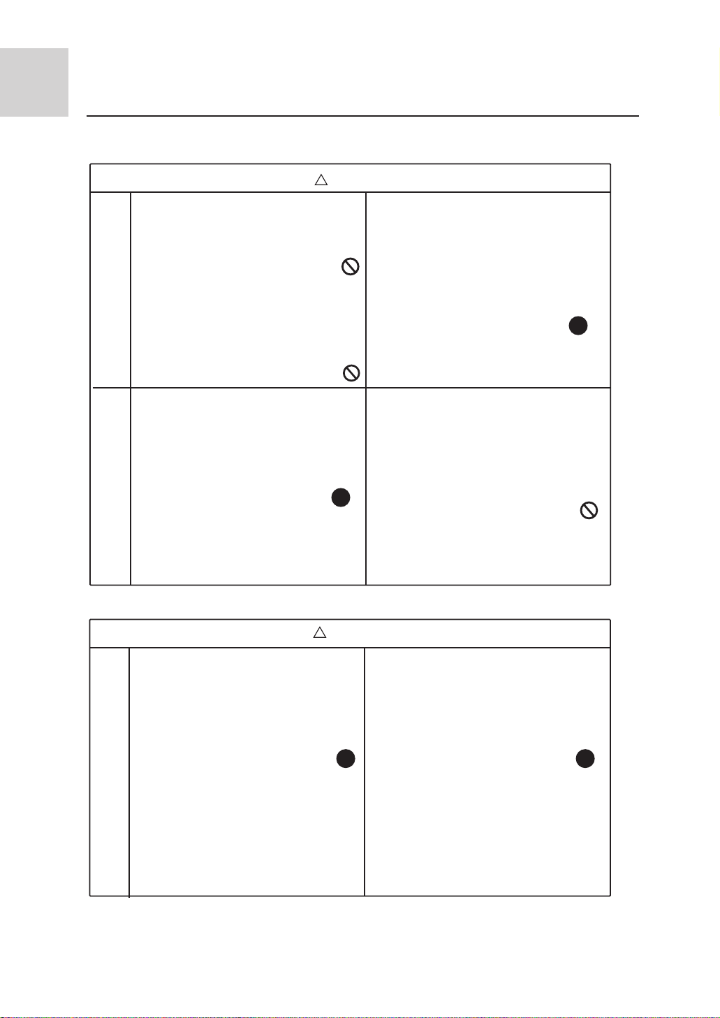
Important Points of Safety
The following four important points of safety and suggestions should be paid great attention:
!
Warning: Misuse may cause fatal result such as death or serious injury etc.
!
Attention: Misuse may cause human injury or damage of machine, in some case
fatal results.
: Content marked with this ìforbiddenî sign should be absolutely forbid den, otherwise may cause damage of machine and human injury of the
user.
: Content marked with this ìcompulsoryî sign should be executed comp-
!
ulsively, otherwise may cause damage of machine and human injury of
the user.
Comply with the following important points of safety.
Put these important points of attention and suggestions nearby and convenient for reference in need.
Hand over this instruction manual to new user if you resell this machine.
!
Warning
l Entrusted Installation
Installation of the machine should
be entrusted to certified person of
after service. Unauthorized install-
Warning for installation
ation may cause water leakage,
electric shock or fire hazard for
improper operation.
l To prevent leakage of refrigerant,
let certified person of after service
do it.
Leakage of refrigerant over certain
consistence may result in shortage
of oxygen. Enough precautions
MUST be done to avoid oxygen
shortage in case of refrigerant lea king if the room where the air conditioner is installed is small.
l The power supply must be fitted with
earth line to ensure valid earthing of
the air-conditioner. No or incomplete
earthing connection may cause the
risk of electric shock.
l Test run
!
After indoor units are installed,all
cassettes hinded models should be
tested.when the units are confirmed
to be normal,other fitments can be
installed.
!
!
!
5
Page 7
Important Points of Safety
!
Warning
l Avoid your body being blown
Warning for use
directly by cold wind for long
period, otherwise your health
may be affected.
l Donít extend your fingers or
any other article into the inlet
or outlet during operation of
the machine for touching re volving fans may cause human
injury or damage of machine.
Warning for move and repair
l When you have to disassemble
and reinstall the machine, entrust
it to after service. Improper inst allation may cause fire hazard,
electric shock or damage of ma chine.
l If something abnormal (e.g.: burnt
smell etc.) occurs, stop running the
machine, shut down the manual
power switch and contact after
service. Continuous operation in
disorder may cause fire hazard or
electric shock etc.
l Unauthorized alteration or repair
work is strictly forbidden. Impr oper alteration or maintenance
may cause fire hazard, electric
shock or water leakage. Repair
work should be entrusted to cert ified person of after service.
!
!
Attention points for installation
l Ensure the drainage hose work
normally during installation.
Improper installation of drainage
can cause water leakage and
damp articles.
l DO NOT install the machine in
place where flammable gas
releases easily to avoid fire
hazard.
!
Attention
!
l Ensure electric leakage breaker
being installed. Electric leakage
breaker MUST be installed,
otherwise electric shock may be
caused.
!
l If the power supply cord is
damaged, call a certified
electrician of the manufacturer
or other maintenance department
to replace it.
6
Page 8
Important Points of Safety
Attention
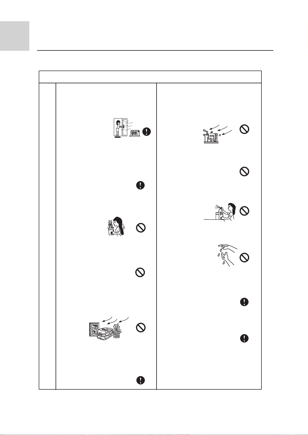
* Ensure ventilation of the room
if the machine is used with
burning facilities. Deficient
ventilation can cause oxygen
shortage.
* Check whether installation
bench of the machine is
damaged after a long period
of use. Machine on damaged
bench may fall down and cause
human injury or other damage.
Attention points for use
* In place where winds produced
by the machine can reach, donít
lay any animals or plants which
may be hurt otherwise.
* Donít put vases containing water
or other else on the unit assembly .
Otherwise, the machine may be
immersed internally and result in
bad electric insulation causing
electric shock.
* The is machine CANNOT be
used for the purpose of prese rving food, animals, plants,
precision instruments and
artwork etc., which may be
destroyed otherwise.
* DONíT lay any burning facilities
in place where winds produced by
the machine can reach. Incomplete
combustion of burning facility may
be caused otherwise.
* DONíT clean the machine with
water. Electric shock may occur
otherwise.
* DONíT put flammable spray
articles nearby or spray them to
the machine. Fire hazard may
occur otherwise.
* DONíT operate switch with wet
hand. Electric shock may occur
otherwise.
* Stop operation and shut down
manual power switch before
cleaning and maintenance.
* The power supply MUST be of
rated voltage and connected with
special electrical supply circuit.
* DONíT replace fuse with ma terial other than fuse of proper
capacity. Replacing fuse with
metal wire or copper etc. can
cause fire hazard or other faults.
7
Page 9
Operating instructions
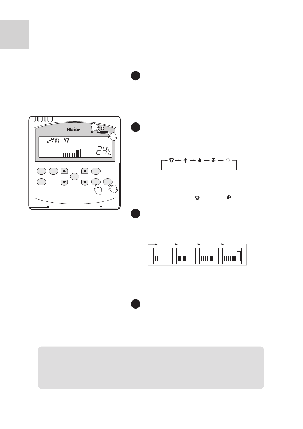
1
Unit start
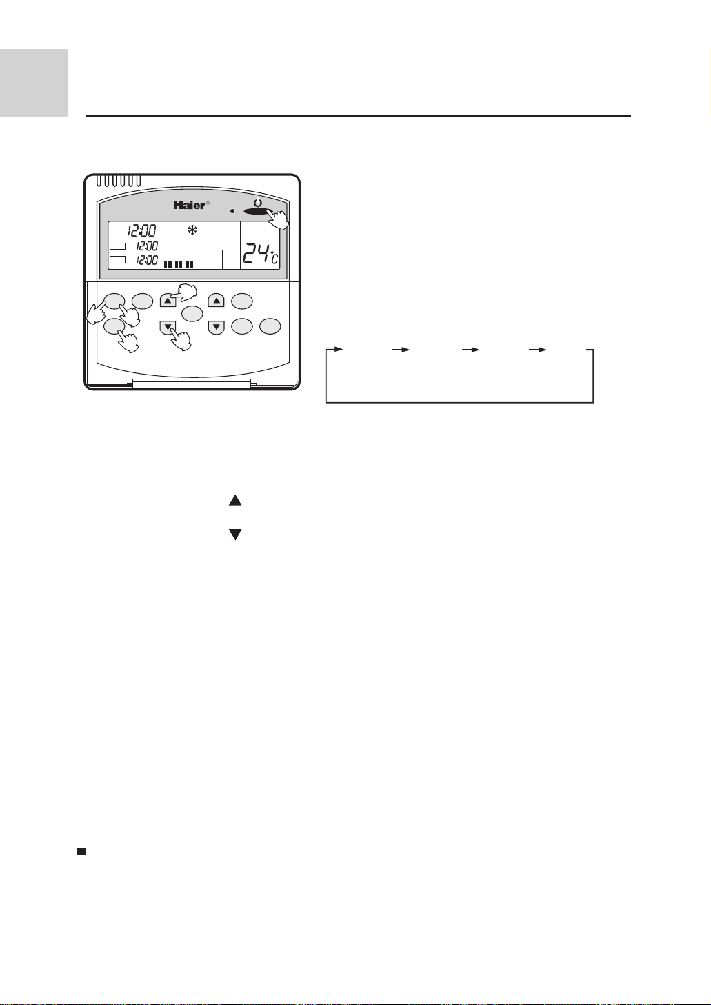
Press the "ON/OFF" key to turn on the unit.
The LCD on the remote controller displays the previous
operating conditions (excluding previous timer, sleep and
louver conditions).
The remote controller operation indicator turns on.
R
4
AM
AUTO
LOW MIN HIGH
ROOM TEMP
1
2
Select operation mode
Press the "MODE" key to alter the working mode. Each
pressing will change the operation mode in the following
sequence:
AUTO, FAN operation
TIMER
SET
CLOCK
TIME
SLEEP
TEMP
SWING
FAN
SPEED
AUTO COOL DRY FAN HEAT
The air conditioner will operate with the displayed running
MODE
2
3
mode.
Select AUTO or F AN operation mode,
the display will stop at " "AUTO, or" " FAN
3
Fan speed adjustment
Press the "FAN SPEED" key to change the fan speed. Every
pressing will change the fan speed in the following sequence:
LOW MID HIGH AUTO
L L M L M H L M H
AUTO
The air conditioner will run at the displayed fan speed.
Note: AUTO fan speed is unavailable in FAN operation mode.
Unit stop
4
Press the "ON/OFF" key to turn off the unit.
The remote controller LCD displays only the clock and room
temperature.
Hints:
The remote controller possesses a memory function which could remember the setting conditions
in each operation mode. Upon next time of operation, you need only to select the operation mode
and the air conditioner will automatically operate with the previous settings without further setting.
(Except for the timer, sleep and louver conditions).
8
Page 10

Operating instructions
COOL, DRY, HEAT operation
Recommended operation mode:
Please use cooling mode in summer
and heating mode in winter.
Please use DRY mode in spring or
autumn humid climate.
Unit start
1
Press the "ON/OFF" key to turn on the unit.
The LCD on the remote controller displays the previous operating conditions (excluding previous timer,
sleep and louver conditions).
The remote controller operation indicator turns on.
Select operation mode
2
Press the "MODE" key to alter the working mode.
Each pressing will change the operation mode in the
following sequence:
5
R
AUTO COOL DRY FAN HEAT
AM
AUTO
LOW
1
SET TEMP
The air conditioner will operate with the displayed
running mode.
Select your desired operation mode and get the display
stop at the corresponding indication.
Select a desired temperature
TIMER
CLOCK
SLEEP
TIME
SET
SWING
TEMP
FAN
MODE
SPEED
3
2
4
3
Press the TEMP setting keys.
Every time pressing the " " key, the temperature
setting will increase by 1oC.
Every time pressing the " " key, the temperature
setting will decrease by 1oC.
Set a suitable temperature value.
4
Fan speed selection
Run in COOL mode when
room temp. is higher than
temp. setting
Temp.setting + 2oC
Temp. setting
Ultra-low air supply
Run in mild DRY mode when
the room temp. reaches temp.
setting +2oC
Press the FAN "SPEED" key to change the fan speed.
Each press will change the fan speed in the following
sequence:
LOW MID HIGH AUTO
L L M L M H L M H
AUTO
The air conditioner will run at the fan speed displayed
on the LCD.
In HEAT operation, after unit is turned on, the air conditioner will send out hot air after a short while in order to
prevent cold draft.
In DRY operation, when the room temperature decreases to 2oC above temperature setting, the air conditioner
will run at low fan speed regardless of the fan speed setting.
Unit stop
5
Press "ON/OFF" key to turn off the unit.
Hints:
The remote controller could remember the setting conditions in each operation mode. Upon next
time turning on the unit, you need only to press the "ON/OFF" key and the air conditioner will
automatically operate with the previous settings. (Except for the timer, sleep and louver conditions).
9
Page 11
Operating instructions
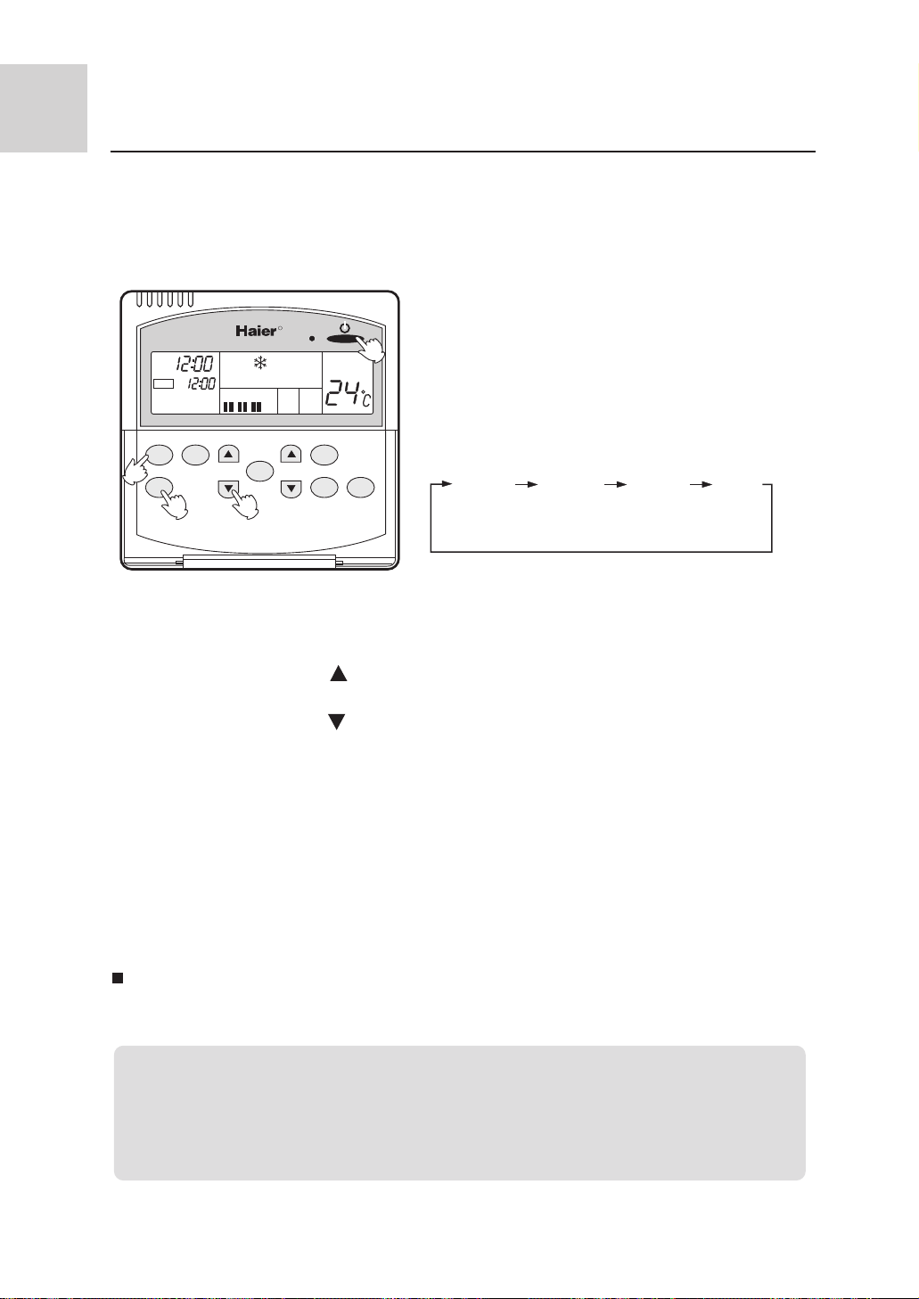
TIMER ON/OFF function
Please adjust the clock before using timer function.
You may set the air conditioner automatically turn on or turn
off when you wake in the early morning, come off work or
after you fall asleep.
1. Set the operation mode after the unit is turned on.
R
FAN
ROOM TEMP
1
MODE
AM
AM
TIMER ON
TIMER
CLOCK
2
SET
4
LOW MIN HIGH
TIME
AUTO
SLEEP
3
SWING
TEMP
SPEED
3. Set time
Press " TIMER SETTING " step keys.
The operation indicator on the remote controller turns on,
and the LCD screen displays the operation mode.
2. Setting the timer mode
Press the "TIMER" key to change timer mode. Each
pressing will change the timer mode indication as follows:
TIMER ON TIMER OFF TIMER ON BLANK
AM
12:00
TIMER ON TIMER OFF TIMER ON-OFF
PM
12:00
Determine a timer mode according to your need subsequently (TIMER ON or TIMER OFF).
The display of TIMER "ON" or TIMER "OFF" now
flashes.
TIMER OFF
AM
12:00
PM
12:00
Every time pressing the " " key will increment the time setting by 10 min, while kept
pressing will increase quickly.
Every time pressing the ì " key will decrement the time setting by 10 min, while kept
pressing will decrease quickly.
The LCD on the remote controller displays the time setting, which could be freely adjusted
within 24 hours.
4. Confirm the setting
After completion of time adjustment, press the "SET" key to confirm the time.
TIMER "ON" or TIMER "OFF" doesnt flash now.
The time display is: Unit starts or stops at x hour x min. (TIMER ON or TIMER OFF).
4
Cancel TIMER mode
Just press "TIMER" key several times until TIMER mode indication disappears.
Hints:
Time should be setting again after a power failure.
The remote controller possesses memory function, when use TIMER mode next time, just
press the "SET" key after mode selecting if time setting is the same as previous one.
10
Page 12
Operating instructions
TIMER ON-OFF operation
1. After unit starts, select your desired operation mode.
The operation indicator turns on and the operation mode is
displayed on the LCD screen.
TIMER ON
TIMER OFF
R
AM
AM
AM
LOW MID HIGH
AUTO
ROOM TEMP
1
2. Timer mode selection
TIMER
CLOCK
2
4
SET
6
3
SLEEP
TIME
5
TEMP
SWING
FAN
MODE
SPEED
TIMER ON TIMER OFF TIMER ON BLANK
AM
12:00
TIMER ON TIMER OFF TIMER ON-OFF
AM
12:00
TIMER OFF
AM
12:00
AM
12:00
Select TIMER ON-OFF mode.TIMER "ON" flashes now .
3. Time setting for TIMER ON
Press "TIMER SETTING" step keys.
Every time pressing the " " key, time setting will increment by 10 min, if kept pressed, it will increase
rapidly.
Every time pressing the " " key, time setting will decrement by 10 min, if kept pressed, it will decreases
rapidly.
The remote controller LCD displays the time setting which could be freely adjusted within 24 hours.
4. Time confirming for TIMER ON
After time setting, press the "SET" key to confirm the time.
"TIMER ON" doesnt flash any longer while "TIMER OFF" starts to flash.
*
Time displayed: Unit starts at x hour x min.
5. Time setting for TIMER OFF
Press "TIMER SETTING" step keys, then follow the same procedure in Time setting for TIMER "ON".
6. Time confirming for TIMER OFF
After time setting, press "SET " key to confirm.
TIMER "OFF " does not flash any longer.
Time displayed: Unit stops at x hour x min.
*
To cancel TIMER mode
l Just press "TIMER" key several times until TIMER mode indication disappears.
l According to the time setting sequence of TIMER ON and TIMER OFF, either Start-
Stop or Stop-Start can be achieved.
1 1
Page 13
Operating instructions
SLEEP function
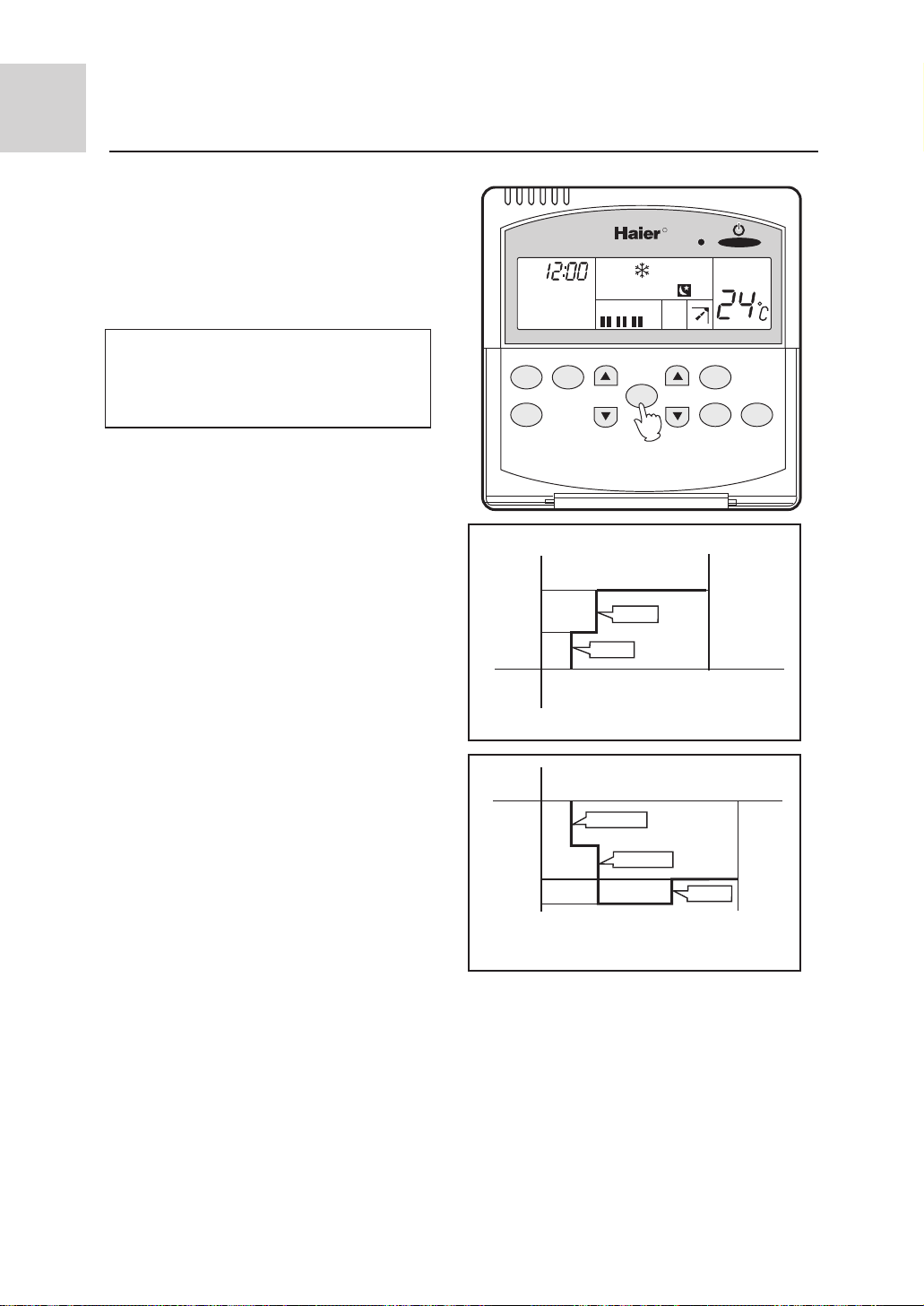
Using SLEEP function
Before using this function, the time must be checked
and set. After the unit starts, set the operation status,
then press "SLEEP" key.
Before going to bed, you can press the "SLEEP"
key on the remote controller and the air conditioner will operate in comfortable SLEEP mode
and bring you a sound sleep.
Operation Mode
In COOL/DRY mode
1 hour after SLEEP mode starts, temp. will become
1*higher than temp. setting. After another 1 hour,
temp. rises by 1* further. The unit will continue
to run for further 6 hours and then automatically
stops. The controlled temperature is higher than
temperature setting so that room temperature wont
be too low for your sleep.
In HEAT mode
(unavailable for cool only models)
1 hour after SLEEP mode starts, temp. will become
2*lower than temp. setting. After another 1 hour,
temp. decreases by 1* further. This temperature
will be maintained for 3 hours before rising by 1*.
The unit will continue to run for further 3 hours and
then stops automatically. The controlled temperature
is lower than temperature setting so that room
temperature wont be too high for your sleep.
R
TIMER
SET
AM
AUTO
LOW MIN HIGH
CLOCK
SLEEP
TIME
TEMP
SWING
FAN
SPEED
SET TEMP
MODE
Sleep operation starts Sleep operation stops
1 hr
Temperature
1 hr
About 6 hr
Rise by 1*
Rise by 1*
Sleep temperature
Unit stops
setting
In COOL/DRY mode
Temperature
setting
1 hr
Decrease by 2*
1 hr
Decrease by 2*
3 hr
Unit stops
About
3 hr
Rise by1*
Sleep temperature
Sleep operation starts Sleep operation stops
In HEAT mode
In AUTO mode
The unit operates in corresponding SLEEP mode
adapted to the automatically selected operation mode.
In FAN mode
SLEEP function is not available.
12
Page 14
Troubleshooting
The following cases are not troubles.
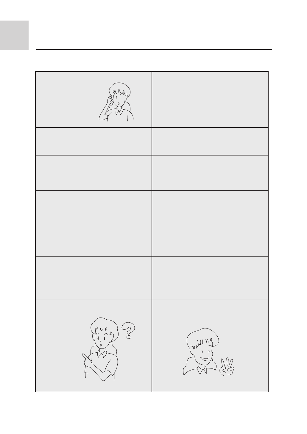
Water flow sound is heard.
"Hua-Hua"
A sound of "Pi-Pa" is generated.
Smells are given off.
During operation, mist or steam are
blown out.
During operation, the air conditioner may
sometimes exhibit a sound of "clatter" or
"rumble". This is the common sound of
refrigerant flow but not a trouble.
This is caused by the thermal expansion
or cold shrinkage of plastics.
Sometimes there are smells in the air flow
from the indoor unit. This is caused by the
smell of cigarettes or paint coatings inside
the unit.
During COOL or DRY operation, the unit
may blow out a thin mist. This is the con-
densate water mist caused by sudden co-
oling of the indoor air blown out from the
indoor unit.
During COOL operation, it automatically
changes to FAN mode.
The system couldnt be re-started immediately
after turning off.The unit can't start?
In order to prevent frost accumulation on
the heat exchanger in the indoor unit,
sometimes it will automatically transfers
to FAN mode, but soon will return to
COOL mode.
This is due to the systems self-protection
function, which prevents it from restarting
in 3 min after stops.
Please wait
for 3 min.
13
Page 15
Troubleshooting
During DRY operation, there is no air
sent out or fan speed cant be changed.
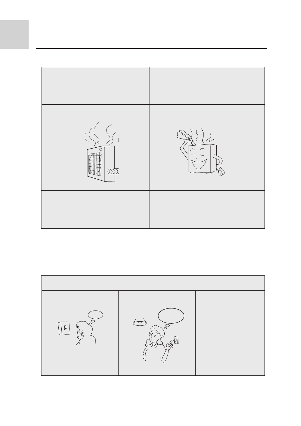
In HEAT mode, the outdoor unit
generates water or steam.
In HEAT mode, the indoor fan still
keeps running even the unit operation
stops.
In DRY operation, when the room temperature reaches 2* higher than temp.
setting,the unit will run at "lOW"fan speed
regardless of fan speed setting.
This occurs during removal of the frost
(in defrosting operation) on the radiator
of outdoor unit.
Defrost operation
After the unit stops, the indoor fan will
continue to run for a while to eliminate
residual heat.
Before asking for after -service to an authorized service center, please check your air
conditioner for the following items
The system couldnt start
Is power on/off switched on?
Is the power supply line
normal?
Is current leakage breaker
triggered?
Power
ON
OFF
failure?
Please do immediately
The power on/off switch is
not at position of "ON".
cut off power supply and
contact the authorized
service center.
14
Page 16
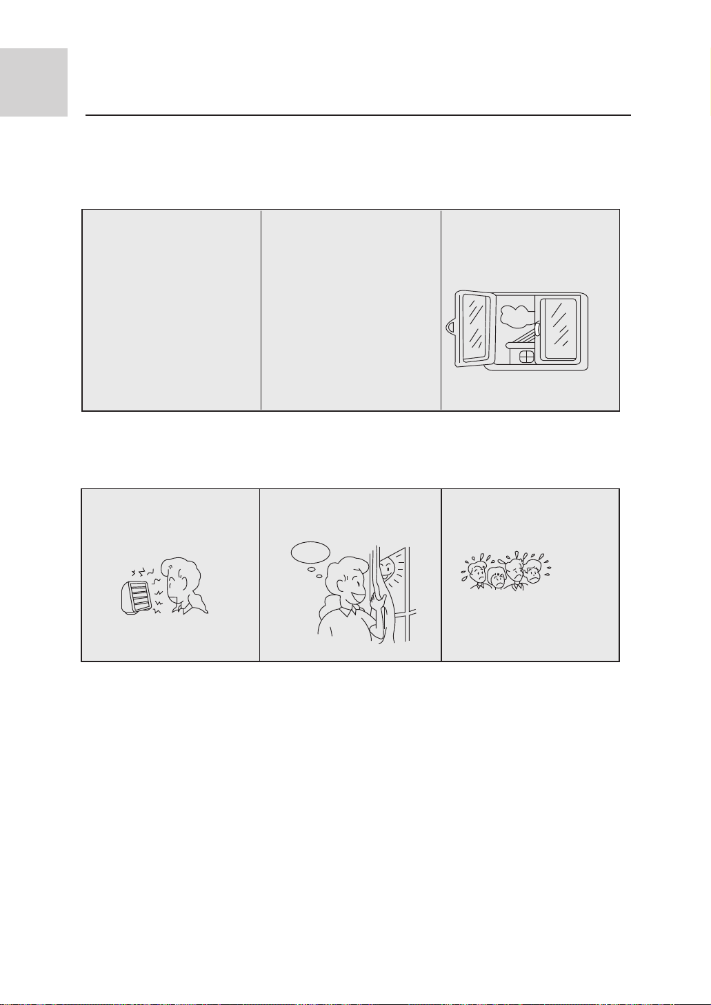
When fault occurs
Poor cooling or heating
Is the operation controller
adjusted as required?
Is there any other heat
source in the room?
Are there any obstructs
before the air inlet or outlet?
Poor cooling
Is there any direct sunlight
into the room?
Is there any door or window
left open?
Are there too many people
in the room?
If, after the above checks and the corresponding corrective actions, the system remains
abnormal operation, or the following facts appear, please turn off the air conditioner and
then contact the local authorized service center.
l Frequent open of fuse or breaker.
l There is water leakage during COOL or DRY operation.
l The operation is abnormal or abnormal sound is heard.
15
Page 17
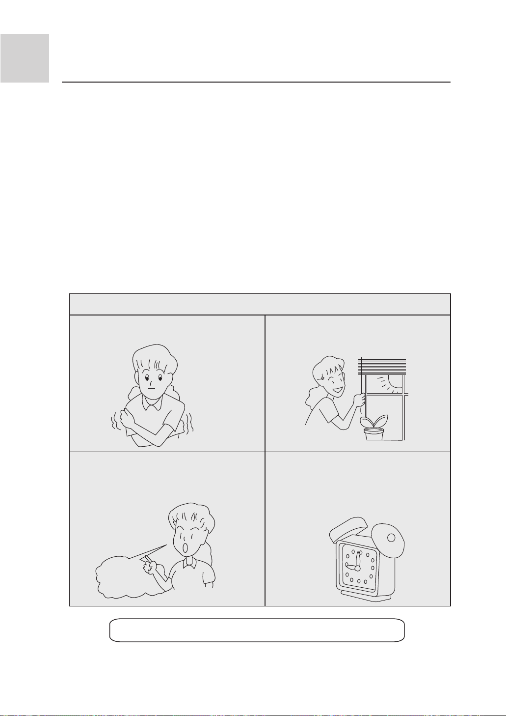
Notice to users
Notice to users
l To ensure proper operation of the system, the user shall follow this instruction manual
to install the unit.
l When handling the air conditioner, please be care not to scratch the case surface.
l This instruction manual describes the installation method aided with the installation
tools specified by Qingdao Haier Air Conditioner Electronics Com., Ltd.
l The maximum length of connection pipe is 50 m, and the maximum difference between
levels of indoor unit and outdoor unit shall be 30 m.
l Please keep the installation instruction manual well for reference in maintenance or
changing installation position.
Information about application
Adjust your desired air flow direction Avoid direct sunlight and gas flow
Keep appropriate room temperature
Too cool or too warm wont benefit
to your health, but causes an increased energy consumption.
Maximum
temperature
Caution: After installation, please confirm no refrigerant leaks.
Effectively use the timer Using
TIMER mode you can enjoy a
comfortable room temperature
when wake up or come back home.
16
Page 18
Installation precautions
Before installing, do read this "Safety precautions" carefully to guarantee the proper installation.
!
The below attentive matters are divided into"
wrong installation occur, it is very possible death and severe injury and other serious accidents will
happen. For those items are listed in
part can also cause serious accidents. Above all, both the two parts are very important contents
related to safety, so they must be obeyed.
After finishing the installation work, do test run to verify everything is normal. After that please
explain the using and maintenance methods to the user. Additionally , give this installation manual
and operation manual to the user and ask them to keep it properly.
Warning
!
The distributing shop, where you bought the air conditioner, or the specified shops shall do the
installation work. If you do the installation work by yourself, the improper installation will cause
water leakage, electric shock fire and other accidents.
The installation work shall be in line with what the installation manual specified. If installation
is not proper, water leakage, electric shock, fire and other accidents will occur .
Install the air conditioner to a place where can definitely stand its weight. Places not firm enough
will cause drop down of unit resulting in body hurt.
The installation work shall be preventive to typhoon and earthquake. If the installation work is
not met with the requirements, overturn of the unit will occur resulting in accidents.
The wiring work shall be done by a qualified person and referred to the " technical standard of
electric equipment" , "indoor wiring regulation" and what the manual specified. Do use
special circuit. If the capacity of the circuit is not enough or bad work, electric shock, fire and other
accidents will happen.
Using the specified cable to do wiring work and connecting firmly and properly. Fix the connecting
part of the terminals to prevent it from the external force.Improper connection and fixing will cause
heating and fire etc. accidents.
Wiring shall be kept in correct shape avoiding extrusion. After installation, the electric box cover
and the external panel shall not nip the wire. Improper installation will cause heating and fire etc.
accidents.
When setting or moving the air conditioner do not let the air and things alike get into the
refrigeration system except the specified refrigerant (R22). If air and other things enter, abnormal high pressure will occur, which easily cause break and body injuries etc. Accidents.
When installing, do use the accessories or specified parts. If not using the parts specified by our
company, water leakage, electric shock, fire and refrigerant leakage will occur .
Do not lead the drainpipe to drain where the sulfur gas may be involved. Otherwise, the poisonous
gas will enter into the indoor.
During installation, if refrigerant leakage occurs, do the ventilation work immediately. As soon as
the refrigerant gas meets fire, poisonous gas will be produce. If the refrigerant gas enters into room
and meet the air blowing heater, heater or stove etc. fire source, the poisonous gas may be produced.
After installation, confirm there is no leakage of refrigerant.
Do not install the unit in a place where the combustible gas may be leaked. In any case the
combustible gas leaks and accumulated around the unit, fire accident will occur.
Do heat insulation work to the refrigerant gas pipes and liquid pipes to reach the purpose of heat
preservation. If the heat insulation measure is not sufficient, water generated by condensing dew
will drip leading to wet the floor and indoor articles.
!
Note
Do grounding work.Do not connect the grounding wire to gas pipe,tap,lighting rod or telephone
line.Improper grounding will cause electric shock.
After electric installation,power on them to do electric leakage test.
Warning
!
" Warning"
" and "
part. But even the items listed in " Note"
!
two parts. When the
Note"
!
17
Page 19
Installation precautions
! Attention
This description does not address to all possible cases. For new requirement and query, please
consult the regional sales center of Haier Air Conditioner General Co., Ltd.
! Warning
This instruction manual must be read carefully before beginning of installation, improper installation may cause accidents and thus bring about machine damage and personal casualty.
Installing tools
1. Screw driver 6. Pipe cutter 10. Leakage detector or soap water
2. Hacksaw 7. Pipe expander 11. Measuring tape
3. Driller of 70mm diameter 8. Knife 12. Scraper
4. Spanner (diameter 17, 27mm) 9. Pinchers 13. Refrigeration oil
5. Spanner (14, 17, 19, 27mm)
18
Page 20
Installation procedure
Electrical requirements
l The power supply shall be connected from the outdoor side. (For models with electric-aided
heating function, the power supply to the indoor unit shall be connected at the indoor side
The power cord size is 3 x (1.25-1.5)mm2, type of YZW).
l A separate power circuit shall be supplied and connected by a qualified electrician according
to the wiring rules specified in the corresponding national standard.
l A current leakage breaker must be installed.
l The connection method of power cord is " Y " type. If the power flexible cord is damaged, it
shall be replaced by the manufacturer or its service department or similar qualified technician
so as to avoid risks.
l Power cord plug: L should be connected to the live wire, N should be connected to the neutral
wire and to the ground wire.
l Connection wire size: 3 x (1.25-1.5) mm2, type of YZW.
l Signal transmission wire size: 2 x (0.75-1.25) mm2 (shielded wire).
l Power cord, connection wire and signal wire shall be provided by the user.
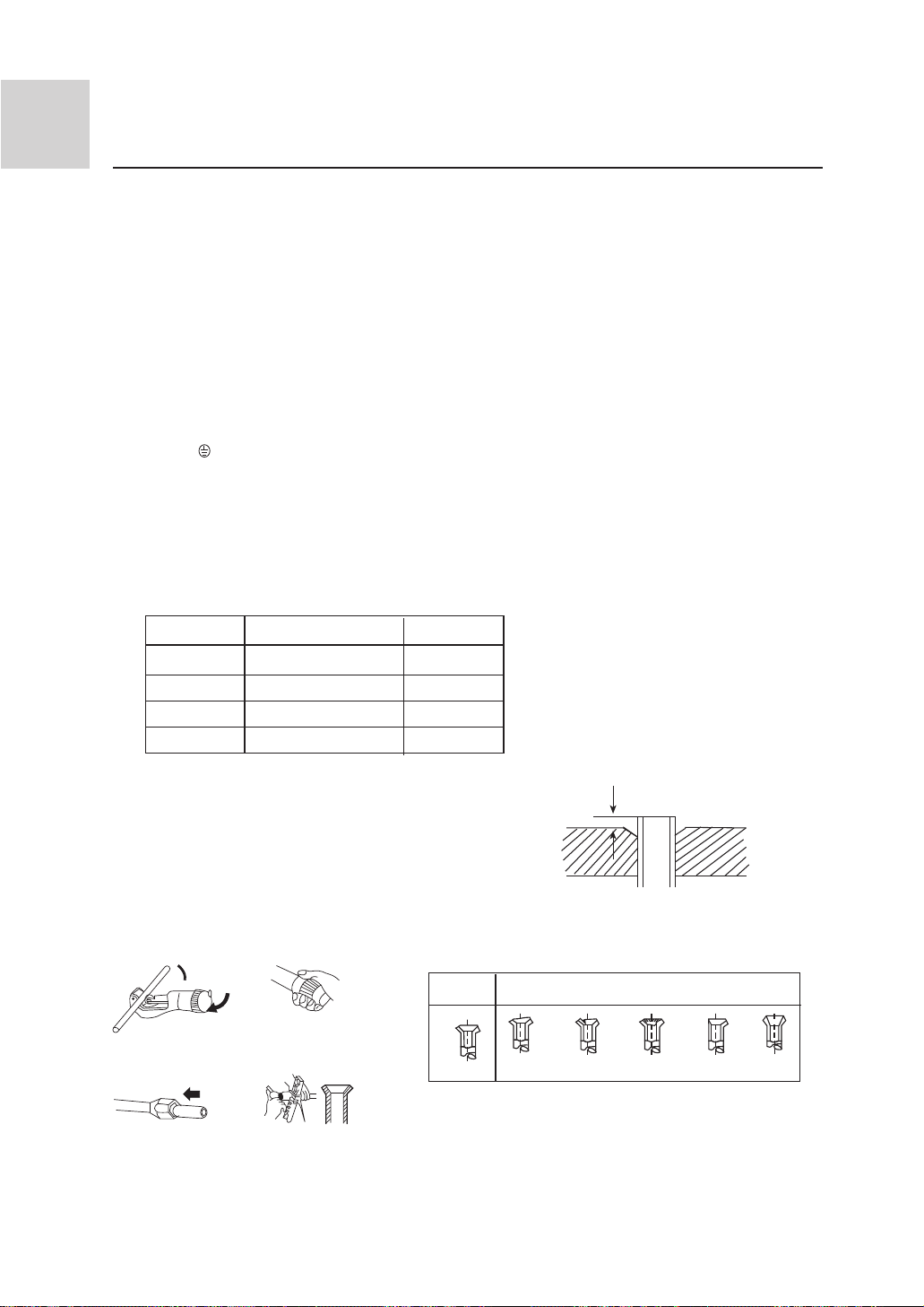
Pipe expansion dimensions as follows:
Specification
Liquid pipe
Liquid pipe
Gas pipe
Gas pipe
Pipe diameter ÿ Size A (mm)
6.35 mm (1/4") 0.8 ~ 1.5
9.52 mm (3/8") 1.0 ~ 1.8
12.7 mm (1/2") 1.2 ~ 2.0
15.88 mm (5/8") 1.4 ~2.2
Pipe cutting and expanding
If the pipe is too long or the flare is damaged,
it needs to be cut or expanded.
1. Pipe cutting 2. Removing burrs
Correct
3.Insertion nut 4. Pipe expansion
A
Pipe expander
Incorrect
Slope Damage Bur Partial Overlong
19
Page 21
Installation procedure
Choosing the installation location
! Caution
Please do not install the unit in places where flammable gases may be leaked. In case
that gas is leaked and accumulated around the unit, it may cause dangers of fire etc.
The indoor unit shall be installed at locations where cold and hot air could evenly circulated.
The following locations should be avoided:
l Places with rich saline matters (seaside regions).
l Places with plenty of gas sulfides (mainly in warm spring areas where the copper tube and
braze weld is prone to corrosion).
l Locations with much oil (including mechanical oil) and steam.
l Locations using organic solvents.
l Places where there are machines generating HF electromagnetic waves.
l Positions adjacent to door or window in contact with high-humidity external air. (Easy to
generate dew).
l Locations frequently using special aerosols.
Indoor unit
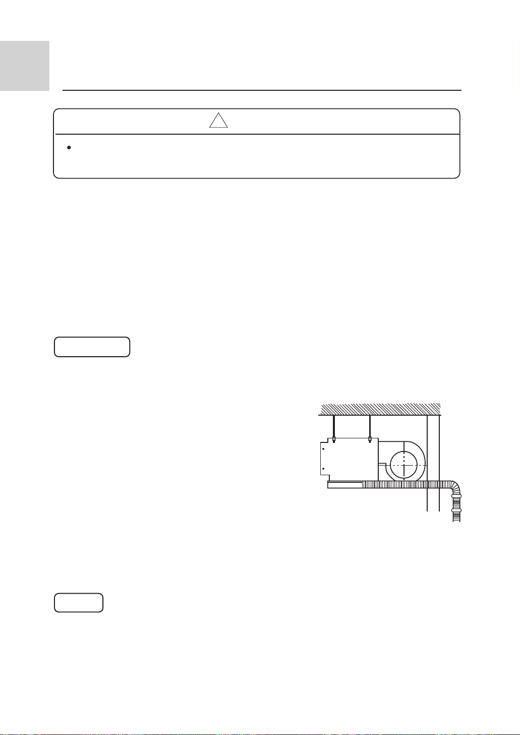
1. Select suitable places the outlet air can be sent to the
entire room, and convenient to lay out the connection
pipe, connection wire and the drainage pipe to outdoor.
2. The ceiling structure must be strong enough to support
the unit weight.
3. The connecting pipe, drain pipe and connection wire
shall be able to go though the building wall to connect
between the indoor and outdoor units.
4. The connecting pipe between the indoor and outdoor
units as well as the drain pipe shall be as short as possible.
(See Figure 1)
5. If its necessary to adjust the filling amount of the
refrigerant, please refer to the installation manual
attached with the outdoor unit.
6. The connecting flange should be provided by the user
himself.
Important
An access port must be provided during installation of indoor unit for maintenance.
Fig 1
20
Page 22
Installation procedure
! Warning
Installation of indoor unit
lThe unit shall be installed at locations enough
to support the unit. If not, the air conditioner
may fall down and cause personal injury.
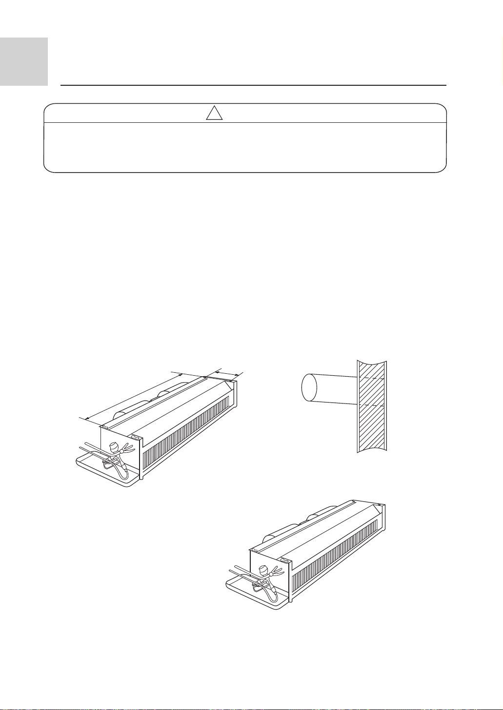
After selecting the unit installation location, proceed the following steps:
1. Drill a hole in the wall and insert the connecting pipe and wire through a PVC wall-through tube
purchased locally. The wall hole shall be with a outward down slope of at least 1/100. (See
Figure 2)
2. Before drilling check that there is no pipe or reinforcing bar just behind the drilling position.
Drilling shall avoid at positions with electric wire or pipe.
3. Mount the unit on a strong and horizontal building roof. If the base is not firm, it will cause
noise, vibration or leakage (see Figure 6).
4. Support the unit firmly.
5. Change the form of the connection pipe, connection wire and drain pipe so that they can go
through the wall hole easily.
lThe unit shall be installed according to the
specifications to resist to strong wind and
earthquake. Improper installation may cause
dangers of unit falling down etc.
Figure showing installation dimensions: (unit:mm)
223
1100
AE182FCAHA
Fig 2
AE092FCAHA
21
Page 23
Installation procedure
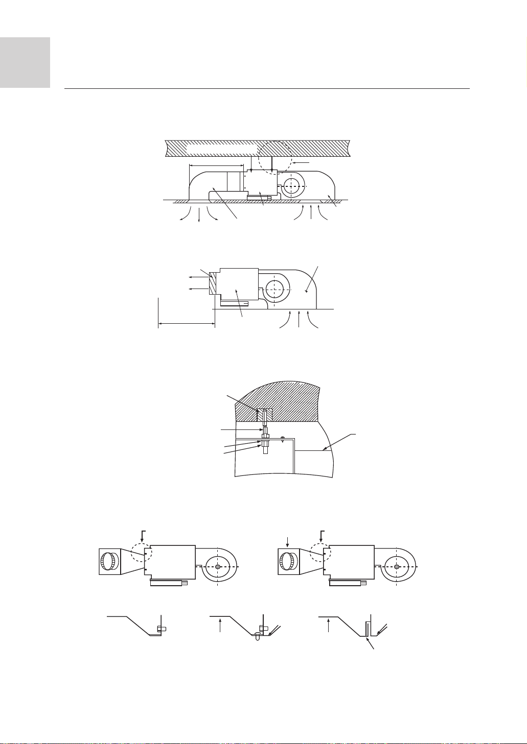
Installation of indoor unit
l When installing the cassette hind type indoor unit, a specially designed return air bellows
shall be installed, as shown in Figure 3, Figure 4.
l The distance between the air duct outlet and the air conditioner air outlet shall not exceed
0.5 m.
Installing building roof
*0.5m
Ceiling
A
Air supply
Air outlet grille
Air supply
No obstacles
within 1 m
M8 broad foundation bolt
M8 suspension screw
M8 broad lock ring
M8 nut
Air outlet duct
Detail A
Unit
Unit
Figure 3
Figure 4
Figure 5
Return air bellows
Return air
Return air bellows
Return air
Unit
B
B Rivet
Detail B
Air supply duct
B
to mount the top
plate with screw
Air supply ductAir supply duct
Figure 6
22
A
Detail A
Unit top plate
Air outlet grille
Page 24
Installation procedure
Installation of indoor unit
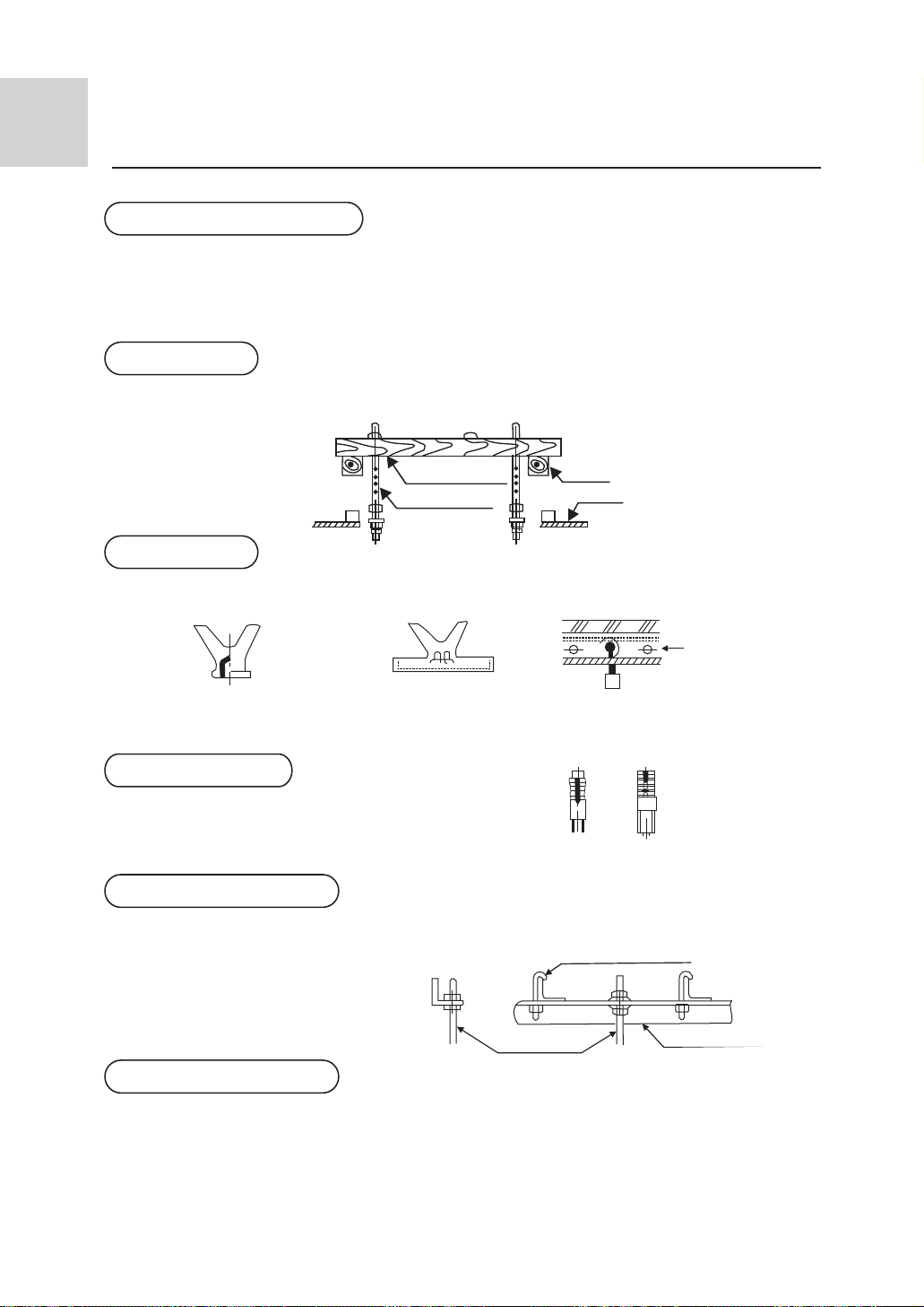
Installing the suspension screw:
Use M8 or M10 suspension screws (4, prepared in the field) (when the suspension screw
height exceeds 0.9 m, M10 size is the only choice). These screws shall be installed as
follows with space adapting to air conditioner overall dimensions according to the original
building structures.
Wooden structure
A square wood shall be supported by the beams and then set the suspension screws.
Square wood
Suspension
screw
New concrete slab
To set with embedded parts, foundation bolts etc.
Knife embedded part
Guide plate embedded part Pipe suspension foundation bolt
Original concrete slab
Use hole hinge, hole plunger or hole bolt.
Steel reinforcement structure
Use steel angle or new support steel angle directly.
Beam
Iron reinforcement
Foundation bolt
Hanging bolt
Suspension screw
Support steel angle
Hanging of the indoor unit
l Fasten the nut on the suspension screw and then hang the suspension screw in the T
slot of the suspension part of the unit.
l Aided with a level meter, adjust level of the unit within 5 mm2.
23
Page 25
Installation procedure
Installation of the remote controller
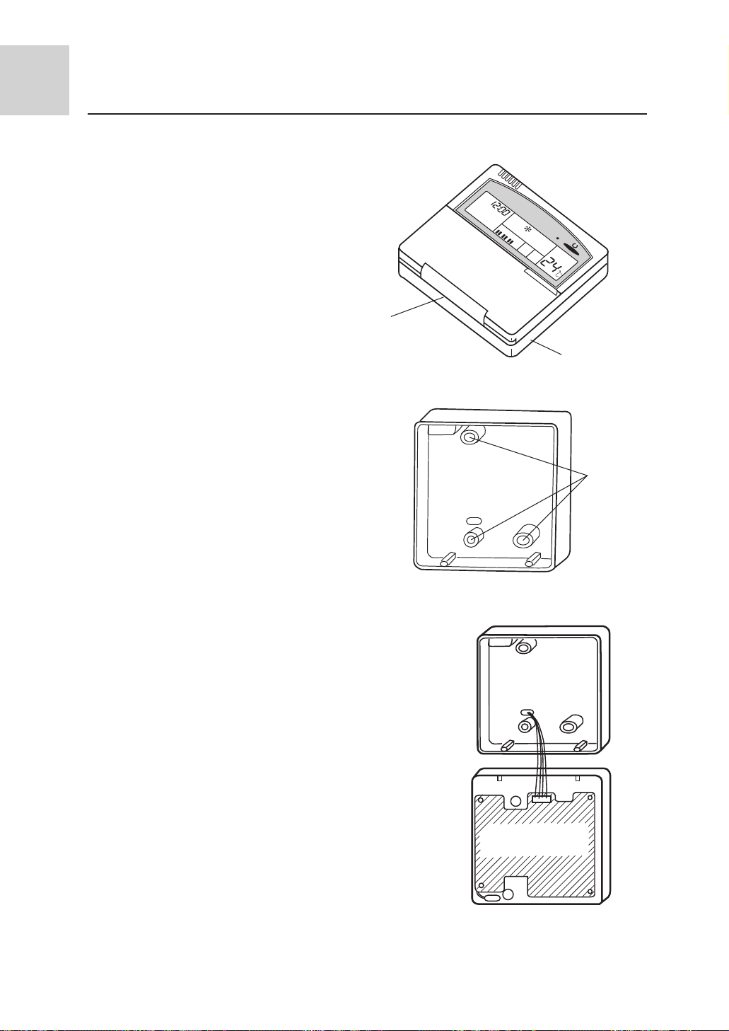
Installation of remote controller
1. Remove the back cover of the remote controller
Firstly detach the remote controller back
cover at the bottom, then detach at the top.
The whole back cover of the remote
controller could be removed.
Remote controller bottom
2. Mount the back cover of the remote controller
Drill 3 holes in the wall corresponding to
the positions of 3 screw holes in the back
cover of the remote controller, subsequently plug a cork into each wall hole. Align
the 3 screw holes in the back cover of the
remote controller with the corks and then
fasten the back cover onto the wall with
wooden screws.
AM
*
*
*
**
Remote controller back cover
Screw
hole
3. Installing the remote controller
Pull the lead cable of the remote controller
out of the wire hole in the back cover to a
suitable length before fit the remote controller with the back cover at the bottom,
and then close at the top.
4. Connecting the lead wires
Connect the lead out terminals of the remote controller with the lead terminals of the
indoor unit using remote controller connecting wire.
24
PCB
Page 26
Installation procedure
Drain pipe
! Caution
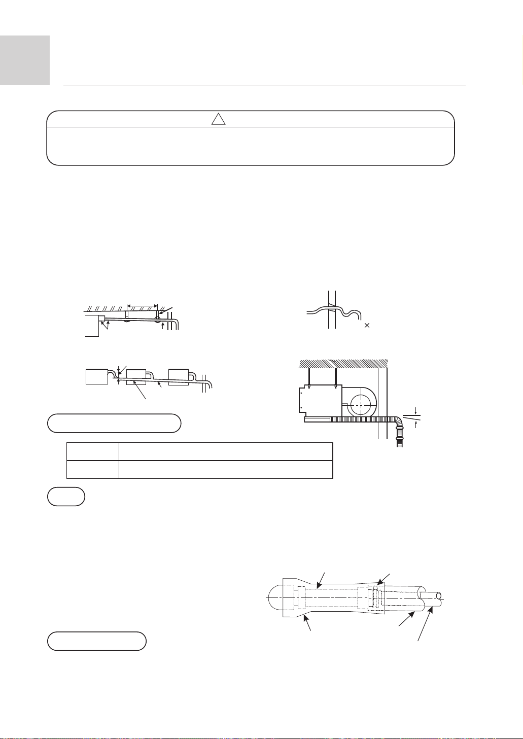
l In order to drain water normally, the drain pipe shall be processed as specified in
the installation manual and shall be thermal insulated to avoid dew generation.
Improper hose connection may cause indoor water leakage.
Requirements
l The indoor drain pipe shall be thermal insulated.
l The connection part between the drain pipe and the indoor unit shall be insulated so as to
prevent dew generation.
l The drain pipe shall be slant downwards (greater than 1/100). The middle part shall not be
of S type elbow, otherwise abnormal sound will be produced.
l The horizontal length of the drain pipe shall be less than 20 m. In case of long pipe, suppo rts shall be provided every 1.5 ñ 2m to prevent wavy form.
l Central piping shall be laid out according to the following figure.
l Take care not to apply external force onto the drain pipe connection part.
1.5m~2m
Insulation
(supplied by the user)
To the largest (app. 10cm)
Down slope above 1/100
Down slope
above 1/100
VP30
Support
S type elbow
Pipe and insulation material
Pipe
Insulation
Rigid PVC pipe VP31.5mm (internal diameter)
Foamed PE with thickness above 10mm
Hose
Drain pipe size: ÿ19.05mm2 (3/4") PVC pipe
The hose is used for adjusting the off-center and angle of the rigid PVC pipe.
l Directly stretch the hose to install without making any deformation.
l The soft end of the hose must be fastened with a hose clamp.
l Please apply the hose on horizontal part
Hose Hose clamp
Insulation treatment:
l Wrap the hose and its clamp until to the
indoor unit without any clearance with
insulating material, as shown in the figure.
Wall
Outside
Slant
Drain pipe (supplied
by the user)
Drain confirmation
Subsidiary insulation
Insulation
Rigid PVC pipe
During trial run, check that there is no leakage at the pipe connection part during water
draining even in winter.
25
Page 27
Installation procedure
Refrigerant piping
! Caution
l In installation, if there is refrigerant gas leakage, please take ventilation measures
immediately. The refrigerant gas will generate poisonous gas upon contacting fire.
l After installation, please verify that there is no refrigerant leakage. The leaked re frigerant gas will produce poisonous gas when meeting fire source such as heater
and furnace etc.
Allowable pipe length and drop
These parameters differ according to the outdoor unit. See the instruction manual attached
with the outdoor unit for details.
Pipe material and size
Pipe material
Model
Pipe size
(mm)
Supplementary refrigerant
The refrigerant supplementation shall be as specified in the installation instructions
attached with the outdoor unit. The added refrigerant shall be R407C.
The adding procedure shall be aided with a measuring meter for a specified amount
of supplemented refrigerant
Requirement
l Overfilling or underfilling of refrigerant will cause compressor fault. The amount of the
added refrigerant shall be as specified in the instructions.
Connection of refrigerant pipe
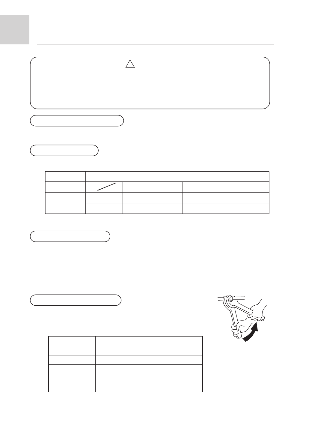
Conduct flared connection work to connect all refrigerant pipes.
l The connection of indoor unit pipes must use double spanners.
l The installing torque shall be as given in the following table.
Connecting pipe
O.D.(mm)
ÿ6.35
ÿ9.52
ÿ12.70
ÿ15.88
Phosphorus deoxidized copper seamless pipe (TP2) for air conditioner
AE182FCAHAAE092FCAHA
Gas side
Liquid side
Installing torque
(N-m)
11.8 (1.2kgf-m)
24.5 (2.5kgf-m)
49.0 (5.0 kgf-m)
78.4 (8.0 kgf-m)
ÿ15.88 ÿ12.70
ÿ9.52
Increased installing
torque (N-m)
13.7 (1.4 kgf-m)
29.4 (3.0 kgf-m)
53.9 (5.5 kgf-m)
98.0 (10.0 kgf-m)
ÿ6.35
Double-spanner
operation
26
Page 28
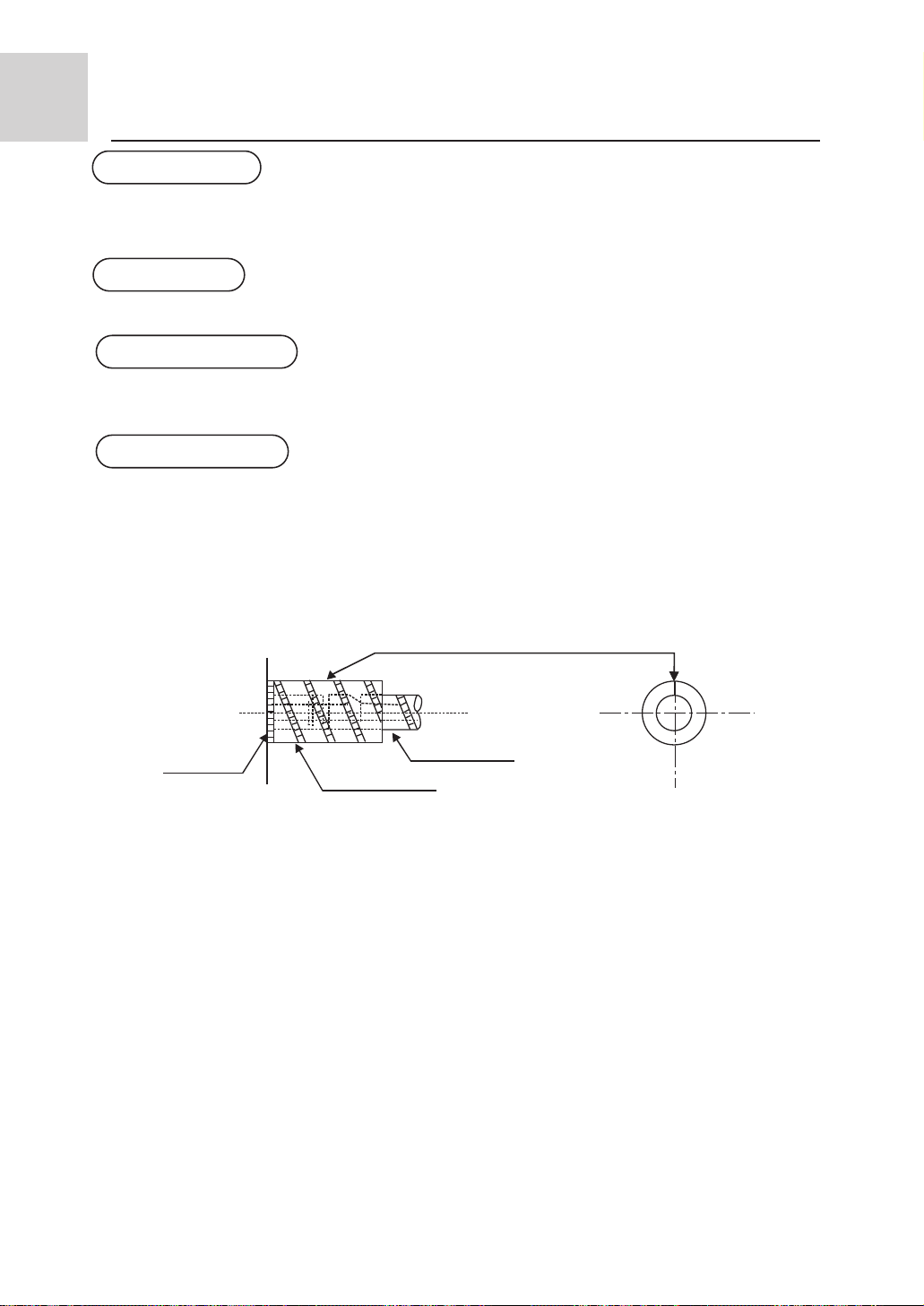
Installation procedure
Vacuum pumping
With a vacuum pump, create vacuum from the stop valve of the outdoor unit.
l Emptying with refrigerant sealed in the outdoor unit is absolutely forbidden.
Open all valves
Open all the valves on the outdoor unit.
Gas leakage detection
Check with a leakage detector or soap water that if there is gas leakage at the pipe
connections and bonnets.
Insulation treatment
Conduct insulation treatment on both the gas side and liquid side of pipes respectively.
During cooling operation, both the liquid and gas sides are cold and thus shall be insulated
so as to avoid dew generation.
l The insulating material at gas side shall be resistant to a temperature above 120*.
l The indoor unit pipe connection part shall be insulated.
The notch upward (Attached detail view)
Refrigerant piping
Indoor unit
Field piping side
Subsidiary insulation tube
27
Page 29
Installation procedure
! Warning
l The electric wiring work shall be conducted by qualified electricians according to the install ation instructions. A separate power circuit shall be used. Insufficient power cord amperage
or improper wiring will cause danger of electric shock or fire.
CElectric wiring
!
l During wiring connection, the power cord shall be of the specified cable and reliably fastened
so that external forces applied to the cable wouldnt transfer to the terminals. Improper conne ction or fastening will cause danger of heating, fire etc.
The power cord must be fitted with a grounding wire.
l Grounding shall be made as specified. Unreliable grounding will cause electric shock. The g rounding wire shall not be connected to the gas pipeline, water pipeline, thunder arrestor and
telephone wire
!
!
! Caution
!
l A current leakage breaker shall be installed, otherwise it electric shock would happen easily.
l If the power cord is damaged, it must be replaced by the manufacturer or its service center or
similar personnel to avoid risks. The power supply to the indoor unit shall be laid in comply ing with the operational instruction manual.
l The electric wiring shall avoid contacting with the high temperature part of the piping so as
to prevent the cable insulation melts and cause dangers.
l After connected on the terminal block, the wires shall be bent to U form and then fastened
with wire clip.
l The control wiring and refrigerant piping may be laid and fastened together.
l Before completion of vacuum pumping of the refrigerant pipe system, do not electrify the in-
door unit.
l The power cord of the indoor unit and connection wiring between indoor and outdoor units
shall be laid out according to the operational instruction manual of the indoor unit.
l The connection of the power cord shall comply with the local regulations.
28
Page 30
Installation procedure
Electric wiring
Wiring connection method : (the wiring diagram is attached inside the machine)
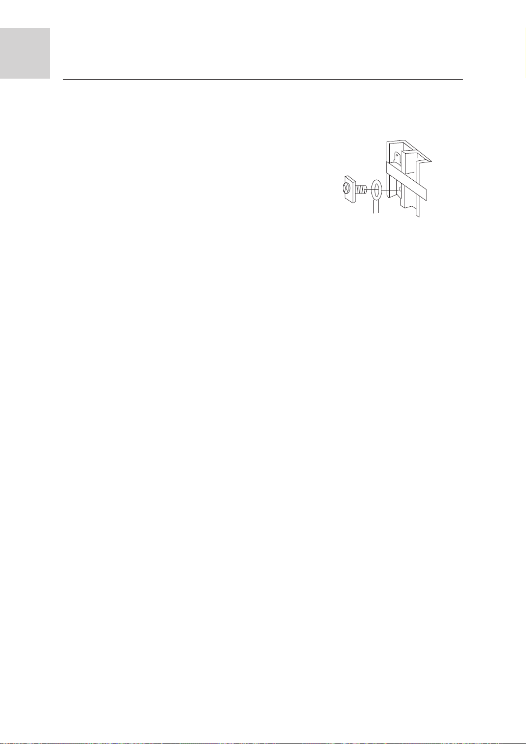
1) Ring terminal connection method
If there is a ring at the end of the connection wire,
the wire connection method is as shown in the right
figure. Remove the terminal screw and insert it
through the ring at the connection wire end, then
connect to the terminal board and fasten the screw.
2) Straight terminal connection method
If there isnt a ring at the end of the connection wire,
the connection method shall be: loosen the terminal
screw, insert the connection wire end completely
into the terminal board and fasten the screw. Pull the
connection wire outwards slightly to confirm it is
clamped tightly.
3) Clamping method of the connection wire
After wire connection is finished, the connection wire
must be pressed tightly with wire clips, which shall
apply to the outer sheath of the connection wire.
Connection method f
or ring terminal
Wire connection for built-in indoor unit
l Insert from outside the connection wire and signal transmission wire through the wall hole
with pipeline already arranged.
l Pull out the front ends of connection wire and signal wire and make a circle on the signal
wire.
l Connect the connection wire according to the connection method and indoor and outdoor
wiring diagram.
l Pull the connecting conductor outwards slightly to confirm it is clamped tightly.
l Connect the plug for connecting the signal wire with the plug of the signal wire connected
from the indoor unit.
l After wire connection is finished, install wire clips using the same method for connection
wire clamping.
Note: When connecting the indoor unit and the outdoor unit, please do connect the wires
with the same color terminals.
Notes:
l Before connecting the conductors between indoor unit and outdoor unit, check for the nu mber on the indoor and outdoor units connecting terminals. Connect the terminals with the
same color and number with a wire.
l Wrong connection would damage the controller of the air conditioner or the machine cou ldnt operate.
l Do not connect the connection wire and signal wire with the same cable. They shall be co nnected respectively to ensure system normal operation.
29
Page 31
Installation procedure
Field setting
Field setting
Field setting the unit number
In order to realize central control of the MRV air conditioning system, its necessary to set
the indoor unit number (control address).
Indoor unit number setting
Indoor unit number setting switch and confirmation of the settings.
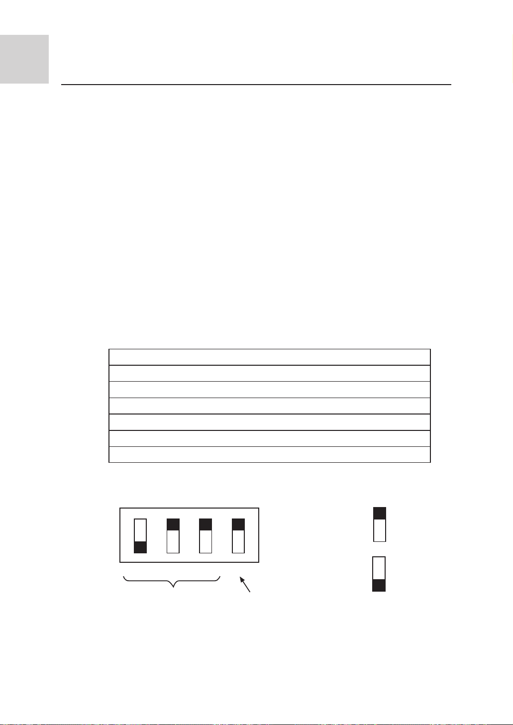
There is a 4-position dial switch for setting the indoor unit number on the computer board
of the indoor unit.
Setting way is as follows:
Before connecting the power supply, please set the indoor unit number manually according
to the following table
Matrix of the dial switch and indoor unit number
Position 1 Position 2 Position 3 Representing unit number
Example:
Setting for No. 2 indoor unit Disabled
0 0 0 1
1 0 0 2
0 1 0 3
1 1 0 4
0 0 1 5
1 0 1 6
1 0 0
Pos.1
Pos.2 Pos.3 Pos.4
: 0
: 1
30
Page 32
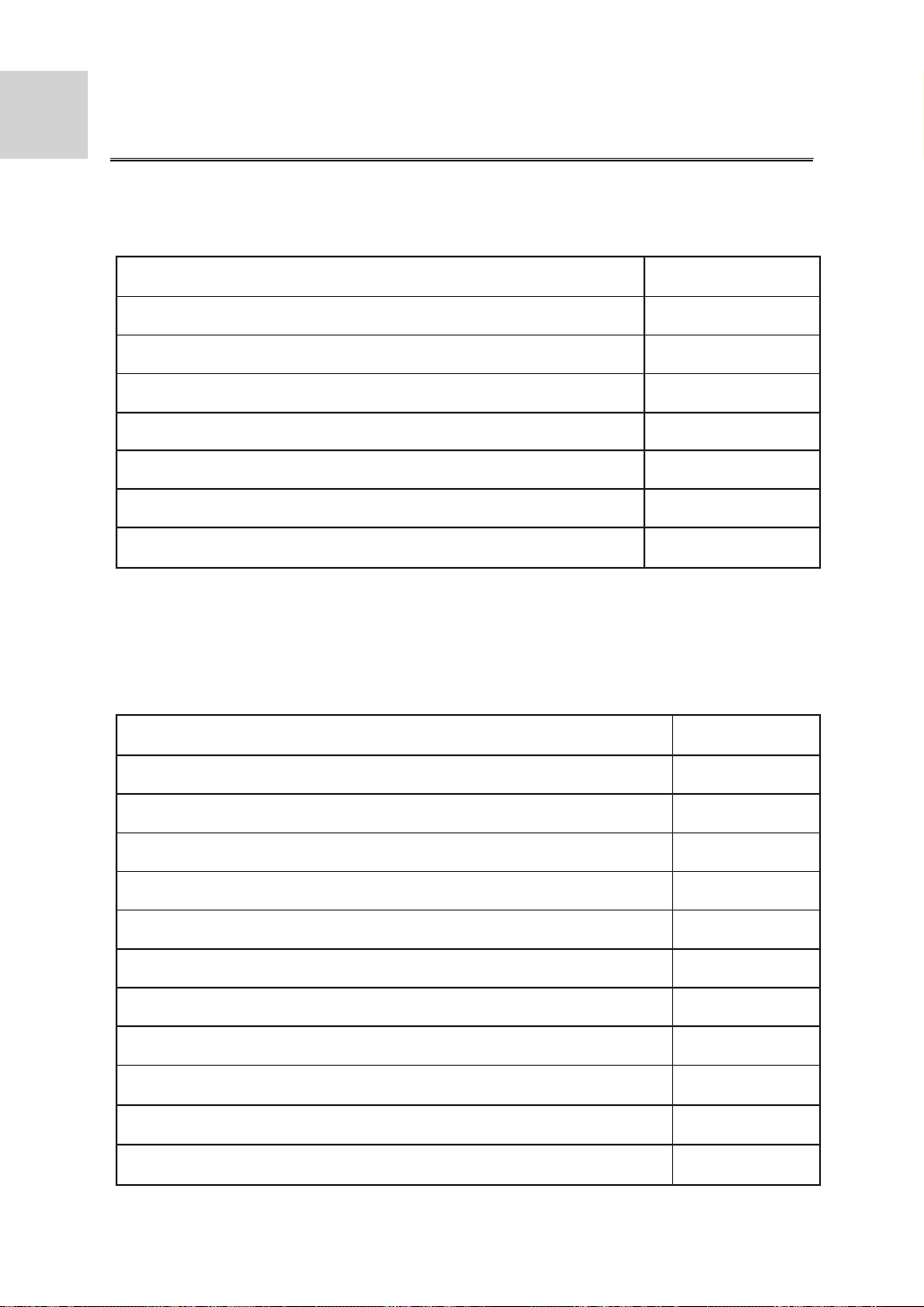
List of troubles
List of displayed troubles on the remote controller
Trouble description
Ambient temperature sensor fault
Indoor unit gas pipe temperature sensor abnormal
Indoor unit and outdoor unit signal transmission abnormal
Faulty communication between indoor unit 846 chip and 808 chip
Indoor unit liquid pipe temperature sensor trouble
Indoor unit and remote controller communication abnormal
Trouble with outdoor unit
List of indicated troubles with outdoor unit (when the remote controller indicates E9,
you may check the indoor unit main board LED1 or outdoor unit main board LED1
(AU242FHAHA), outdoor unit main board LED (ALARMA or ALARMB) (AU422FIA
HA*AU422FIAIA).
Trouble description
Outdoor unit defrost temperature sensor abnormal
Displayed code
E1
E2
E3
E5
E6
E7
E9
LED flash times
1
Outdoor unit ambient temperature sensor abnormal
Compressor suction temperature sensor abnormal
Compressor discharge temperature sensor abnormal
Outdoor unit AC overcurrent protection
Outdoor unit DC undervoltage protection
Outdoor unit power module overcurrent protection
Trouble with outdoor unit EEPROM
Compressor discharge gas too hot protection
Abnormal communication between outdoor unit 857 chip and 808 chip
Outdoor unit system pressure too high protection
31
2
3
4
6
7
9
10
11
12
13
Page 33
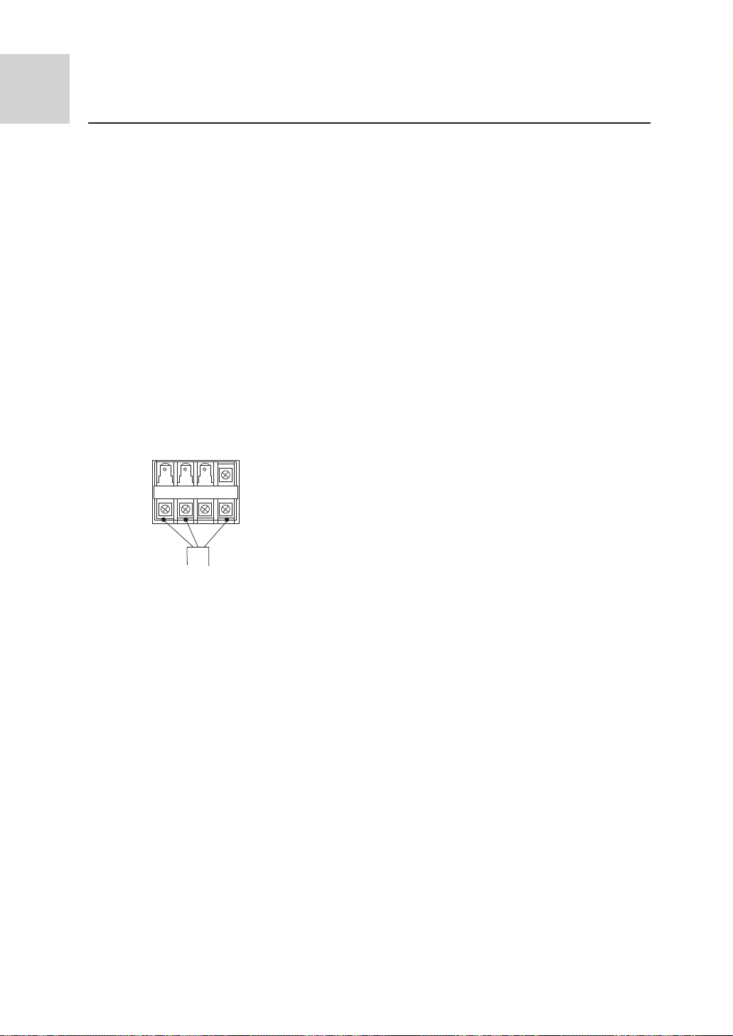
Installation check and trial operation
Check if the drain pipe and connection wires are arranged properly.
The drain pipe shall be put below. The connection wire shall be put above. Be sure to wrap
the drain pipe (especially the indoor part and the part inside the machine) with thermal insulating materials.
The drain pipe shall be made into slope. Avoid bulging up or down or phenomena shown
right figure in the run.
Installation check
* Do the supply voltage meet the requirement? * Could the drainage water completely
discharged to outdoor
*Are the power cord and the indoor/outdoor * Is there any gas leakage at the pipe joints?
connection wire connected properly?
Are the wires pressed firmly?
*Is the noise too big?
WT
*Do the terminal numbers of the indoor/outdoor connection wire coincide with each other?
Is the pipe connection part thermally insulated?
Is the indoor unit mounted firmly and reliably?
BK
YW/GN
Trial operation
The installation serviceman must conduct a trial operation and check:
* Does the temperature regulator work normally?
*Does the installation location selection meet the related requirements?
Wrap with the protective plastic tape
Wrap the connection pipe, the drain pipe and the connection wire together with PVC tape.
Caution:
The connection pipe must be wrapped individually with insulating material from down to up.
32
 Loading...