

MRV Communications Fiber Driver EM316LX User Manual

EM316LX
Console Server Module
User’s Guide
451-0330F

All rights reserved. No part of this publication may be reproduced without the prior written consent of
MRV Communications, Inc. The information in this document is subject to change without notice and
should not be construed as a commitment by MRV Communications, Inc. MRV Communications, Inc.
reserves the right to revise this publication, and to make changes in content from time to time,
without obligation to provide notification of such revision or changes. MRV Communications, Inc.
assumes no responsibility for errors that may appear in this document.
Copyright © 2005 by MRV Communications, Inc.
Should you experience trouble with this equipment, please contact one of the following
support locations:
• If you purchased your equipment in the Americas, contact MRV Americas
Service and Support in the U.S. at 978-952-4888. (If you are calling from outside the
U.S., call +001 978-952-4888.)
• If you purchased your equipment outside the Americas (Europe, EU, Middle-East,
Africa, Asia), contact MRV International Service and Support at (49) 6105/2070.
NOTE: The EM316LX is based on an LX-Series device. Therefore, this document refers to the
documentation set for the LX.
2
451-0330
FCC Notice
This equipment has been tested and found to comply with the limits for a
Class A digital device, pursuant to Part 15 of the FCC Rules. These limits
are designed to provide reasonable protection against harmful
interference when the equipment is operated in a residential installation.
This equipment generates, uses, and can radiate radio frequency energy
and, if not installed and used in accordance with the instructions, can
cause harmful interference to radio communications. However, there is
no guarantee that interference will not occur in a particular installation.
If this equipment does cause harmful interference to radio or television
reception, which can be determined by turning the equipment off and on,
the user is encouraged to try to correct the interference by one or more of
the following measures:
• Reorient or relocate the receiving antenna.
• Increase the separation between the equipment and receiver.
• Connect the power cord of the equipment into an outlet on a circuit
that is different from that to which the receiver is connected.
• Consult the dealer or experienced radio/TV technician for help.
CAUTION
451-0330
Changes or modifications not expressly approved by MRV
Communications, Inc. could void the user's authority to operate the
equipment.
BSMI Notice
3

VCCI Notice
This is a Class A product based on the standard of the Voluntary Control Council for
Interference by Information Technology Equipment (VCCI). If this equipment is used in a
domestic environment, radio disturbance may arise. When such trouble occurs, the user may
be required to take corrective actions.
EXPORT NOTICE
MRV models contain 128-bit encryption software. Export of this product is restricted under
U.S. law. Information is available from the U.S. Department of Commerce, Bureau of Export
Administration at www.bxa.doc.gov.
4
451-0330

Table of Contents
Preface ................................................................................................................................... 13
Customer Support.............................................................................................................................13
Other Documentation .......................................................................................................................14
Overview of the EM316LX .................................................................................................... 15
Conventions.......................................................................................................................................15
System Specifications .......................................................................................................................17
Installing the EM316LX......................................................................................................... 19
Hardware Installation ......................................................................................................................19
Unpack and Inspect the Unit..................................................................................................... 19
Package Contents ....................................................................................................................... 19
EM316LX Indicators and Interfaces................................................................................................20
Front Panel LEDs ....................................................................................................................... 20
Environmental and Installation Considerations ............................................................................21
General Installation..........................................................................................................................21
Follow all Safety Regulations .................................................................................................... 21
Unpacking the Unit .................................................................................................................... 22
Determine the Best Location for the Chassis ........................................................................... 22
General Precautions ................................................................................................................... 22
Plug in the Chassis ..................................................................................................................... 22
Unit Installation ...............................................................................................................................23
Cable Connections ............................................................................................................................24
Connecting the Ethernet Interface ............................................................................................ 24
Connect Serial Device Cables .................................................................................................... 24
Connecting Your Management Station ..................................................................................... 25
Modem Port (Optional) .....................................................................................................................25
Powering On......................................................................................................................................25
System Login and Passwords ...........................................................................................................26
Configuring the EM316LX for the First Time...................................................................... 27
Configuring the EM316LX Unit for the First Time From the LX DIAG Port...............................27
First Time Quick Configuration ................................................................................................ 27
Assigning an IP Address via the Network ................................................................................ 29
Manually Setting the IP Address Via the CLI ................................................................................30
Assigning an IP Address for Booting/Runtime From the EM316NM Module ..............................31
Setting Your ppciboot IP Address for Booting From Network ................................................. 31
Assigning a Runtime .................................................................................................................. 33
Accessing and Configuring the Graphical User Interface (GUI) ...................................................33
Configure Mode........................................................................................................................... 37
Menu Mode.................................................................................................................................. 38
Software Upgrades ...........................................................................................................................39
451-0330
5

IP Configuration Menu.....................................................................................................................39
Booting from Defaults.......................................................................................................................39
Accessing and Configuring Additional Features.............................................................................39
Connecting to the EM316LX via Telnet or SSH ....................................................................... 39
Accessing from a Terminal Attached to an EM316LX Serial Port .......................................... 40
Additional Considerations ................................................................................................................40
Command Line Interface (CLI) Tree Structure ..............................................................................41
Additional Considerations for an Internet Environment ...............................................................42
Autobauding Feature........................................................................................................................42
Reinitializing/Powering Off the Unit...............................................................................................42
Alternative Port Capabilities ................................................................................................ 43
Sensor (Temperature/Humidity) Ports ............................................................................................43
Connecting the Temperature/Humidity Sensor........................................................................ 43
IR-5150 Power Strip Management ..................................................................................................44
Connecting the IR-5150.............................................................................................................. 45
IR-4800 Power Strip Management ..................................................................................................46
Connecting the IR-4800.............................................................................................................. 46
Using LX Ports as Alarm Inputs and Control Outputs ..................................................................47
Alarm Inputs Setup and Usage ................................................................................................. 48
Control Output Setup and Usage .............................................................................................. 49
Appendix A - Technical Specifications ............................................................................... 51
Appendix B - Factory Defaults............................................................................................. 53
ppciboot Factory Default Settings....................................................................................................54
Appendix C - POST Test Error Codes................................................................................. 55
Error Code Definitions......................................................................................................................55
Appendix D - Cabling the EM316LX .................................................................................... 57
Cabling Considerations ....................................................................................................................57
Serial Device Connectors............................................................................................................ 57
Diagnostic Port Connector (Port 0)............................................................................................ 57
10/100 Connector ........................................................................................................................ 58
Ordering Cables .......................................................................................................................... 58
Modular Adapters .............................................................................................................................58
Pin Assignments ......................................................................................................................... 58
Connecting to the Diagnostic Port (Port 0)......................................................................................60
Modem Control/Hardware Flow Control .........................................................................................60
RJ-45 Wiring Considerations ...........................................................................................................61
Modular Adapters (RJ-45 to DB-25) ................................................................................................61
MRV Communications 8-Wire Cabling ...........................................................................................64
6
451-0330

Appendix E - Customer Support ......................................................................................... 67
Contact Information .........................................................................................................................67
Americas Support ....................................................................................................................... 67
International Field Offices ......................................................................................................... 67
International Support................................................................................................................. 69
Manual Information .........................................................................................................................70
Glossary.............................................................................................................................................70
Ordering Information .......................................................................................................................70
451-0330
7

8
451-0330

Figures
LX-Series EM316LX1 (1 Port) Front Panel (w/Modem) ........................................................... 20
LX-Series EM316LX2 (2 Port) Front Panel............................................................................... 20
Remove the Required Number of Blank Panels. ....................................................................... 23
Align the Edges of the EM316 to the Rail Inside the Chassis and Then Insert the Unit....... 23
Basic Menu Structure ................................................................................................................. 41
Connecting the Temperature/Humidity Sensor ........................................................................ 44
Connecting the IR-5150 .............................................................................................................. 45
Connecting the IR-4800 .............................................................................................................. 46
Typical Alarm Inputs Connections ............................................................................................ 48
Typical Interface Design for Control Output Signals ............................................................... 50
Serial Device Connector (RJ-45) Signal Assignments .............................................................. 57
10/100 Connector Assignments .................................................................................................. 58
DB-25 Pins................................................................................................................................... 60
Adapter Wiring, EM316LX Series to DTE ................................................................................ 61
Adapter Wiring, RJ-45 to DB-9, EM316LX Series to DTE ....................................................... 62
Adapter Wiring, EM316LX Series to DCE ................................................................................ 63
Modular Cables for RTS/CTS Flow Control (Eight-Wire), Concurrent with Modem Control Sig-
nalling.......................................................................................................................................... 65
451-0330
9

10
451-0330

Tables
EM316LX Specifications ............................................................................................................. 51
Temperature/Humidity Sensor Specifications .......................................................................... 52
EM316LX Factory Defaults ........................................................................................................ 53
POST Test Error Codes ..............................................................................................................55
451-0330
11

12
451-0330

Preface
This guide contains all the information you need to get the EM316LX up and running.
This guide is organized as follows:
•Preface - Describes the manual’s organization and how to contact customer support.
• Chapter 1 – Provides an overview of the EM316LX, including supported communication speeds,
software requirements, and conventions.
• Chapter 2 – Describes how to install and connect the EM316LX Series, as well as the unit’s
LEDs and connectors.
• Chapter 3 – Explains how to configure the unit for the first time, access the Graphical User
Interface, install Java Runtime Environment (JRE), and connect to the EM316LX Series via
telnet and SSH.
• Chapter 4 – Describes alternative port capabilities, including temperature/humidity sensors,
IR-4800/5150 power control units, and using LX ports as alarm input and control output port
points.
• Appendix A – Provides the electrical, environmental, and physical requirements for the
EM316LX installation.
• Appendix B - Lists the factory default settings.
• Appendix C – Provides the error code definitions for the POST test error codes.
• Appendix D - Describes how to cable the EM316LX unit.
• Appendix E - Lists customer support contact information.
Customer Support
Should you experience trouble with this equipment, please contact your MRV Americas Service and
Support customer representative in the USA at 978-952-4888. International customers call +011 978952-4888.
451-0330
13

Preface
Other Documentation
Other manuals in the LX documentation set are:
• LX-Series Commands Reference Guide - Describes each individual command in the LX CLI tree.
• LX-Series Configuration Guide - Provides information on network configuration, initial setup,
how to set up for remote console functions, RADIUS, and system administration. Provides basic
information regarding the Network Management System (NMS), and procedures on how to use
the Management Information Base (MIB) structure (as pointers to objects in the devices) to
manage these units.
• Software Release Notes - Cites supported features as well as any notes and restrictions for the
current software version.
14
451-0330

The EM316LX is a secure chassis card communication server that is designed for applications
requiring secure console or serial port management. The EM316LX provides the most secure and
robust feature set to meet your remote console management and terminal server needs. The
EM316LX includes the most comprehensive security features, such as per port access protection,
RADIUS, LDAP, Secure Shell v2.0, PPP PAP/CHAP, dial-back, on-board database, menus, and
others.
The EM316LX console management solution enables centrally located or remote personnel to connect
to the console or craft ports of any network element or server. This serial connection allows
administrators to manage and configure the remote network devices and servers, as well as perform
software upgrades as if attached locally.
Currently, the EM316LX hardware provides port densities of 1 serial port plus a V.90/K56 flex
Internal modem plus port 0 for local management, or 2 async serial ports plus port 0 for local
management.
Conventions
Chapter 1
Overview of the EM316LX
451-0330
The following conventions are used throughout this guide:
• User prompt – The user prompt is (for example) InReach:0> for Non-superusers or InReach:0>> for
superusers. The prompt will change based on a login user profile, as configured by the Superuser.
The 0 represents the session number.
15

Overview of the EM316LX
• Configure Mode prompt – A sample configure mode prompt is Async 1-2:0 >>, where Async
is a reminder that tells you which part of the configuration you are in, 1-2 is the range of ports
any operation will affect, 0 is a session number, and >> indicates superuser mode. To get to the
Async 1-2:0 >> prompt, you must first type port async 1 2 at the Config:0 >> prompt.
Note that you do not add a dash between the range numbers in port async 1 2.
• Command execution – Unless otherwise specified, commands are executed when you press
<RETURN>.
• Keyboard characters (keys) – Keyboard characters are represented using left and right angle
brackets (< and >). For example, the notation <CTRL> refers to the CTRL key; <A> refers to the
letter A; and <Enter> refers to the RETURN key.
• Typographical conventions – The following typographical conventions are used:
Monospace Typeface – indicates text that can be displayed or typed at a terminal (i.e.,
displays, user input, messages, prompts, etc.).
Italics – are used to indicate variables in command syntax descriptions.
• Help Key (?) - At any prompt level, you can press ? to display the available commands at that
level. The only time this is not true is if you are in the midst of entering a command. If ? is at the
end of a partial command, the LX displays a list of valid arguments to assist you in adding to the
current command line.
16
• Tab - Press the Tab button to complete a partially entered command. You must enter the first
three characters of a command for autocomplete to work. If the command is already complete, the
Tab button displays available commands.
• Command Recall - The up arrow recalls previously used commands.
• Ctrl-F – Moves forward to the next session.
• Ctrl-B – Moves back to the previous session.
• Ctrl-L – Returns you to the Local Command Mode.
• Ctrl-K – Clears the current command line.
NOTE: You must press the Enter key after you type Ctrl-F, Ctrl-B, Ctrl-L, or Ctrl-K.
451-0330

System Specifications
The following table lists important system specifications:
Item Description
Interface DTE RS-232 - RJ-45
Serial Line Speed 134.5 bps to 230 Kbps
Ethernet Interface 10/100 Auto Sensing
Default Serial Line Speed 9600 bps
Overview of the EM316LX
451-0330
17

Overview of the EM316LX
18
451-0330

Hardware Installation
This section explains how to install an EM316LX Communications server and place it into operation.
Unpack and Inspect the Unit
Place all packing materials back into the shipping carton and save the carton. (If you need to return
the unit to MRV Communications or your distributor, you should return it in the original carton.)
Package Contents
The EM316LX unit shipping carton contains the following items:
• One 8-wire RJ-45 serial crossover cable.
• One female DB-9 to RJ-45 adapter.
• One software/documentation CD.
• EM316LX Console Server Module User’s Guide
Chapter 2
Installing the EM316LX
451-0330
19
Installing the EM316LX
EM316LX Indicators and Interfaces
This section explains the EM316LX unit’s indicators and interfaces.
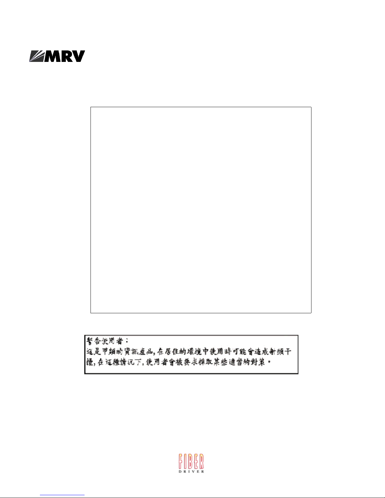
Front Panel LEDs
This section explains the front panel LEDs (see Figure 1 and Figure 2).
MODEM
Port
(optional)
RCV
LINK
EM316LX
DIAG/
MGMT
Port
EM316LX
DIAG/
MGMT
Port
DIAG/MGMT
1
Serial
Port 1
2/MODEM
10/100
FLT
OK
100
10/100
Interface
FLT LED (Fault)
OK LED (System OK)
100 Mbps LED
Figure 1 - LX-Series EM316LX1 (1 Port) Front Panel (w/Modem)
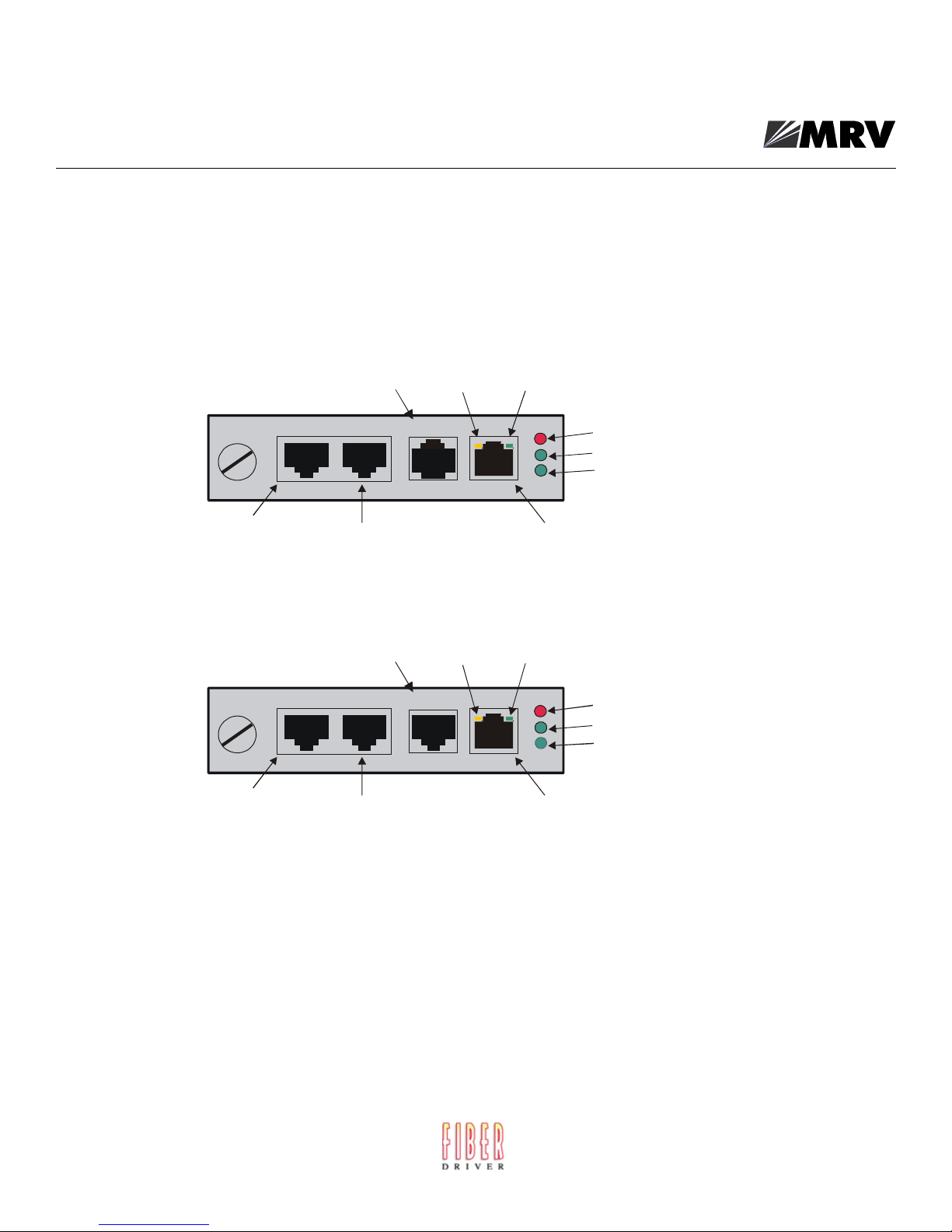
Serial Port 2
DIAG/MGMT
1
Serial
Port 1
RCV LINK
2/MODEM
10/100
FLT
OK
100
10/100
Interface
FLT LED (Fault)
OK LED (System OK)
100 Mbps LED
Figure 2 - LX-Series EM316LX2 (2 Port) Front Panel
FLT
Solid red indicates a fault condition exists or maintenance is required. This LED remains on until the
initial Power On Self Test (POST) completes successfully.
OK
Solid green indicates the system’s voltages are normal and the unit has passed the POST test.
20
451-0330

RCV
The RCV LED is one of two integral LEDs on the 10/100 Ethernet RJ45 jack. This yellow LED flashes
to indicate receive activity on the link.
LINK
This green LED defaults to a “link good” indicator. If the link is present and operating, the LED
comes ON.
100 Mbps
This green LED indicates speed. If the link is 100 Mbps, the LED is lit.
Environmental and Installation Considerations
• Unit must be installed in an environment not exceeding 85% humidity, noncondensing, 0° - +50°
C (32°-122° F).
• Do not choose a location where the unit will be exposed to direct sunlight or subjected to vibration.
• Do not place an object on the side(s) of the unit that might block airflow through the unit.
• Fits all 2-, 3-, or 16-slot Fiber Driver chassis.
Installing the EM316LX
General Installation
Follow all Safety Regulations
Eliminate static electricity in the workplace by grounding operators, equipment, and devices
(components and computer boards). Grounding prevents static charge buildup and electrostatic
potential differences. Transporting products in special electrostatic shielding packages averts
electrical field damage.
An effective workplace should be outfitted with the following items:
• ESD protective clothing/smocks: Street clothing must not come in contact with components or
computer boards since the various materials in clothing can generate high static charges. ESD
protective smocks, manufactured with conductive fibers, are recommended.
• Electrostatic shielding containers or totes: These containers (bags, boxes, etc.) are made of
specially formulated materials, which protect sensitive devices during transport and storage.
• Antistatic or dissipative carriers: These provide ESD protection during component movement in
the manufacturing process. It must be noted that antistatic materials alone will not provide
complete protection. They must be used in conjunction with other methods such as totes or
electrostatic shielding bags.
451-0330
21

Installing the EM316LX
• Dissipative tablemat: The mat should provide a controlled discharge of static voltages and must
be grounded. The surface resistance is designed such that sliding a computer board or component
across its surface will not generate more than 100 V.
• Personal grounding: A wrist strap or ESD cuff is kept in constant contact with bare skin and has
a cable for attaching it to the ESD ground. The purpose of the wrist strap is to drain off the
operator’s static charge. The wrist strap cord has a current-limiting resistor for personnel safety.
Wrist straps must be tested frequently to ensure that they are undamaged and operating
correctly. When a wrist strap is impractical, special heel straps or shoes can be used. These items
are effective only when used in conjunction with a dissipative floor.
• ESD protective floor or mat: The mat must be grounded through a current-limiting resistor. The
floor or mat dissipates the static charge of personnel approaching the workbench. Special
conductive tile or floor treatment can be used when mats are not practical or cause a safety
hazard. Chairs should be conductive or grounded with a drag chain to the flooring.
Unpacking the Unit
Verify that no visible damage has been caused to the outer box. Remove all material from the packing
box and confirm receipt of the following:
• Fiber Driver chassis unit
• User’s manual (this manual in printed format or on a CD)
In the unlikely event that anything is missing, contact your authorized dealer or representative. If it
becomes necessary to return the unit, repackage the unit in its original box.
Determine the Best Location for the Chassis
Affix the chassis to a 19” rack using the enclosed rack mount ears, or place the unit on a secure, flat
surface. Ensure that the unit is within reach of the necessary connections (i.e. power outlet, Ethernet
connections, and, if the chassis will be monitored via serial port, and either a PC, UNIX workstation,
or modem).
General Precautions
Make sure there is enough space to pull and connect both the electrical and optical cables without
stressing them beyond the manufacturer’s limitation (bend radius minimum).
Plug in the Chassis
Connect the power cord (s) to the chassis and an outlet. Turn the power switch(es) to ON position. The
wide-ranging power supply adjusts to any outlet.
22
451-0330
 Loading...