

MRV Communications EM316SW-XY User Manual
EM316SW-XY
Fast Ethernet Multi-Function
Media Converters
User Guide
PN 1288003-001
Revision D2
December 12, 2008

Fiber Driver® EM316SW-XY
Table of Contents
1 Preliminary Considerations.............................................................................................................iv
1.1 Trademarks and Copyright ...........................................................................................................................iv
1.2 Customer Support.........................................................................................................................................iv
1.3 Specific Document Information.....................................................................................................................iv
1.4 Latest Revision and Related Documents......................................................................................................iv
1.5 MRV Regulatory Compliance........................................................................................................................ v
1.6 General Safety..............................................................................................................................................vi
1.7 Electrical Safety ............................................................................................................................................vi
1.8 Laser Safety.................................................................................................................................................vii
1.9 Passive Laser Equipment Safety.................................................................................................................vii
2 Module Introduction..........................................................................................................................1
2.1 Features........................................................................................................................................................1
2.1.1 Loopback...............................................................................................................................................2
2.1.2 Link Integrity Notification (LIN) ..............................................................................................................3
2.1.3 LIN with Far End Fault Indication (FEFI)...............................................................................................3
2.1.4 Redundancy...........................................................................................................................................3
2.2 Modes of Operation ......................................................................................................................................4
2.2.1 Dual Repeater (Fiber and Copper)........................................................................................................5
2.2.2 Dual Converter.......................................................................................................................................6
2.2.3 Redundant Link .....................................................................................................................................7
2.2.4 Mixed-Media Switch (4-Port)................................................................................................................. 8
3 Preparation and Installation .............................................................................................................9
3.1 Unpacking the Fiber Driver Module..............................................................................................................9
3.2 Front Panel Description ..............................................................................................................................10
3.2.1 Distances.............................................................................................................................................10
3.2.2 SFP Ports ............................................................................................................................................10
3.2.3 LED Definitions....................................................................................................................................10
3.2.4 LED Display Information......................................................................................................................11
3.3 DIP Switches............................................................................................................................................... 12
3.3.1 Block Locations ...................................................................................................................................12
3.3.2 Switch Functions and Default Settings................................................................................................13
Module Installation............................................................................................................................................16
Cleaning Fibers.................................................................................................................................................18
3.3.3 Working with SFPs..............................................................................................................................19
3.3.3.1 Cleaning SFPs..............................................................................................................19
3.3.3.2 Mylar Tab SFP Modules ...............................................................................................20
3.3.3.3 Actuator/Button SFP Modules.......................................................................................21
3.3.3.4 Inserting an Actuator/Button SFP Module.....................................................................21
3.3.3.5 Bale Clasp SFP Module................................................................................................22
4 Module Management.......................................................................................................................23
4.1 Serial Console Interface..............................................................................................................................24
4.2 MegaVisionJ Embedded GUI Management ...............................................................................................24
4.3 EM316LNXNM-OT Command Line Interface (CLI)....................................................................................25
4.3.1 EM316LNXNM-OT Boot and CLI Login ..............................................................................................26
4.3.2 CLI Navigation.....................................................................................................................................27
4.3.3 Login Context Commands and Examples...........................................................................................28
4.3.3.1 “?” .................................................................................................................................28
4.3.3.2 “show chassis”..........................................................................................................29
4.3.3.3 “show slots”..............................................................................................................29
4.3.3.4 “show version”..........................................................................................................30
4.3.3.5 “show log”..................................................................................................................30
PN 1288003-001, Rev D2
i

Fiber Driver® EM316SW-XY
4.3.3.6 “show groups”............................................................................................................31
4.3.3.7 “show users”..............................................................................................................31
4.3.3.8 “show running-config”...........................................................................................32
4.3.3.9 “show startup-config”...........................................................................................33
4.3.3.10 Displaying and Saving System Parameters................................................................34
4.3.4 Configuration Context..........................................................................................................................35
4.3.4.1 Restoring Default Parameters.......................................................................................35
4.3.4.2 Configuring System Parameters...................................................................................36
4.3.5 Chassis Context ..................................................................................................................................37
4.3.5.1 “show”...........................................................................................................................37
4.3.5.2 Other Commands..........................................................................................................38
4.3.6 Slot Context Commands and Examples..............................................................................................39
4.3.6.1 “?” .................................................................................................................................40
4.3.6.2 “list”...........................................................................................................................41
4.3.6.3 “show”...........................................................................................................................42
4.3.7 Port Context Commands and Examples.............................................................................................45
4.3.7.1 “?” .................................................................................................................................45
4.3.7.2 “list”...........................................................................................................................49
4.3.7.3 “show”...........................................................................................................................49
4.3.7.4 “description”............................................................................................................51
4.3.7.5 “show defaults” .......................................................................................................52
4.3.7.6 “show config”............................................................................................................53
4.3.7.7 “shutdown” and “no shutdown”................................................................................53
4.3.7.8 “lin”.............................................................................................................................54
4.3.8 RJ-45 Port Commands........................................................................................................................55
4.3.8.1 “auto-neg-adv”..........................................................................................................55
4.3.8.2 “auto-negotiation”.................................................................................................55
4.3.8.3 “mdi-pinout”..............................................................................................................56
4.3.8.4 “duplex”.......................................................................................................................56
4.3.8.5 “speed”.........................................................................................................................56
4.3.9 SFP Port Commands...........................................................................................................................57
4.3.9.1 “loopback”..................................................................................................................57
4.3.9.2 “lin”.............................................................................................................................57
4.3.9.3 “select-link”............................................................................................................58
4.4 Configuration Examples..............................................................................................................................59
4.4.1 Repeater Mode....................................................................................................................................59
4.4.2 Converter Mode...................................................................................................................................61
4.4.3 Redundant Mode.................................................................................................................................64
4.4.4 Switching Mode ...................................................................................................................................65
5 Appendix ..........................................................................................................................................67
5.1 Technical Specifications .............................................................................................................................67
5.2 Operating Environment...............................................................................................................................67
5.3 Troubleshooting ..........................................................................................................................................67
PN 1288003-001, Rev D2
ii

Fiber Driver® EM316SW-XY
Table of Figures
Figure 1 -- Loopback on FO1 while FO2 is in normal operation........................................................................... 2
Figure 2 -- Dual Repeater Mode ...........................................................................................................................5
Figure 3 -- Dual Converter Mode ..........................................................................................................................6
Figure 4 -- Redundant Link Mode .........................................................................................................................7
Figure 5 -- Switching Mode ...................................................................................................................................8
Figure 6 -- Unpacking............................................................................................................................................9
Figure 7 -- EM316SW-XY front panel .................................................................................................................10
Figure 8 -- EM316SW-XY front panel .................................................................................................................11
Figure 9 -- DIP switch locations .......................................................................................................................... 12
Figure 10 -- Remove the required blank panels.................................................................................................... 16
Figure 11 -- Module installation (not all chassis are shown).................................................................................17
Figure 12 -- Correctly inserted Fiber Driver module in a powered chassis...........................................................17
Figure 13 -- Cleaning cartridge .............................................................................................................................18
Figure 14 – Contaminated fiber and clean fiber....................................................................................................18
Figure 15 -- SFP cleaners..................................................................................................................................... 19
Figure 16 -- Mylar Tab on SFP Module.................................................................................................................20
Figure 17 -- Insertion of a Mylar Tab SFP Module................................................................................................20
Figure 18 -- Removal of a Mylar Tab SFP Module ...............................................................................................20
Figure 19 – Actuator/Button SFP Module .............................................................................................................21
Figure 20 -- Insertion of an Actuator/Button SFP Module.....................................................................................21
Figure 21 -- Removal of an Actuator/Button SFP Module.....................................................................................21
Figure 22 -- Bale Clasp SFP Module ....................................................................................................................22
Figure 23 -- Insertion of a Bale Clasp SFP Module ..............................................................................................22
Figure 24 -- Removal of a Bale Clasp SFP Module..............................................................................................22
Figure 25 -- EM316LNXNM-OT general commands for EM316SW-XY modules................................................25
PN 1288003-001, Rev D2
iii

Fiber Driver® EM316SW-XY
1 Preliminary Considerations
1.1 Trademarks and Copyright
All trademarks are the property of their respective holders.
MRV Communications reserves the right to make changes to technical specifications and
documentation without notice in order to improve reliability, function, or design. The user assumes
sole responsibility for applying the information supplied herin.
Copyright © 2008 by MRV Communications, Inc. All rights reserved.
1.2 Customer Support
Before contacting customer support, look for software updates, technical specifications, and
frequently asked questions (FAQ) online at the MRV support website: http://service.mrv.com
The website includes information regarding software updates, technical specifications, frequently
asked questions (FAQ), and contact information.
Contact help online by sending email to support@mrv.com
http://service.mrv.com/support/forms/supportcall.cfm
MRV customer support telephone numbers:
MRV Americas (US, Canada, Latin America)
MRV Europe +49-6105-2070
MRV International +972-4-993-6200
Include the following important information when opening a support case.
• Site ID or company name
• Contact information
• Model or product name
• Serial number
• Top assembly revision (see label on device)
• Brief problem or question including a description of the host network environment
• Attenuation data for applicable high-speed fiber links
• Urgency of the issue
.
+1-800-435-7997 or +1-978-952-4888
or through the website request link at
1.3 Specific Document Information
Document Number: P/N 1288003-001, Rev D2
Document: EM316SW-XY User Guide
Release Date: December 12, 2008 1:36:06 PM
1.4 Latest Revision and Related Documents
The latest revision of MRV documents may be found at: http://www.mrv.com
MRV produces Release Notes for Fiber Driver modules as required.
.
.
PN 1288003-001, Rev D2
iv

Fiber Driver® EM316SW-XY
1.5 MRV Regulatory Compliance
Contact your sales representative for more regulatory compliance information regarding specific
MRV products or product families.
Fiber Driver Chassis
Compliance: FCC Part 15 (Class A); IC (Class A); EMC Directive: Emission (Class A) and
Immunity; LVD Directive: Electrical Safety; CE Marking; TUV CUE Mark (Canada, USA, EU);
GOST; RoHS Directive, WEEE Directive: Wheelie Bin Mark; ETSI, NEBS, C-Tick
Fiber Driver Modules
Compliance: FCC Part 15 (Class A); IC (Class A); EMC Directive: Emission (Class A) and
Immunity; LVD Directive: Electrical Safety; RoHS Directive, WEEE Directive: Wheelie Bin Mark;
ETSI
Optical and Copper Transceivers
Compliance: FCC Part 15 (Class A); IC (Class A); EMC Directive: Emission (Class A) and
Immunity; LVD Directive: Electrical Safety; CE Marking; TUV; UL, CSA, RoHS Directive, ETSI,
NEBS, compliant with EN 60825-1/A1:2002 Safety of Laser Products
PN 1288003-001, Rev D2
v
Fiber Driver® EM316SW-XY
1.6 General Safety
WARNING: Two people must lift large cabinet chassis. Lift with your legs and a straight back
to prevent injury. Lift with both hands, grasping underneath the lower edge. To prevent
damage to the chassis and components, do not lift the chassis with the handles on the power
supplies and interface processors, or by the plastic panels on the front of the chassis. These
handles are not designed to support the weight of the chassis.
WARNING: Do not stack unsecured equipment. Falling equipment can cause severe bodily
injury and equipment damage.
WARNING: To prevent bodily injury when mounting or servicing this equipment in a rack,
take all precautions to ensure that the system remains stable. Follow the guidelines below:
— Mount devices from the bottom of an empty rack.
— Mount the heaviest rack devices at the bottom of the rack.
— Install rack stabilizing equipment before mounting or servicing rack devices.
WARNING: Do not operate the equipment with the covers removed. Ensure that all modules
are installed, empty slots are covered and lasers outputs plugs are in place.
WARNING (Proposition 65): Some Fiber Driver products may contain chemicals known to
the State of California to cause cancer, birth defects, or other reproductive harm.
CAUTION: To prevent overheating the equipment, do not operate it in an area that exceeds
the maximum recommended ambient temperature. To prevent airflow restriction, provide at
least 3 inch (7.6 cm) of clearance around the ventilation openings.
CAUTION: Only trained and qualified service personnel (see IEC 60950-1) should install,
replace, or service the equipment.
1.7 Electrical Safety
WARNING: This equipment is intended to be grounded. Ensure that the host is connected to
earth ground during normal use.
WARNING: Use only shielded and grounded cables to ensure compliance with FCC rules.
WARNING: Electrical equipment relies on the protective devices in the building installation
for protection against short-circuit, over-current, and earth (ground) fault. Ensure that the
protective devices in the building installation are properly rated to protect the equipment.
Listed or certified fuse or circuit breaker must be used on all current-carrying conductors.
WARNING: Install the equipment near power outlet. The power cord plug is the equipment
main disconnecting device and must be easily accessible at all times. Unplug the power cord
before you work on a system that does not have an on/off switch.
CAUTION: The equipment is not intended for direct copper connection to Public Switched
Telephone Network or Telecommunication Network (EU) connection ports.
Install MRV equipment in accordance with applicable building and electrical codes such as:
NFPA NEC 70, CEC, Part 1, CSA C22.1, IEC 60364, BS7671, etc.
Provide proper grounding when servicing and operating electrical equipment to avoid
electrostatic discharge (ESD) that can damage equipment. Use antistatic carriers to transport
exposed electronic devices, protective clothing including grounding straps, antistatic table
and floor mats, furniture grounding, and any other safety devices recommended by the
industry.
PN 1288003-001, Rev D2
vi
Fiber Driver® EM316SW-XY
1.8 Laser Safety
WARNING: Do not open laser devices for service. Removing the cover may cause exposure
to harmful laser beams. Return defective laser devices to the vendor for service.
WARNING: Un-terminated connectors or fiber cable ends may emit invisible laser radiation.
Do not view them directly with optical instruments such as eye loupes, magnifiers, or
microscopes. The amplified laser output can dramatically increase eye hazard.
WARNING: This equipment is intended for use with Class 1 pluggable (SFP, XFP,
GBIC)fiber optics transceivers that carry a label indicating the following specifications:
– Classification as a Class 1 Laser product.
– Compliance with Food and Drugs Administration Center for Radiological Health (FDA
CDRH) performance standards, 21 CFR, 1040.10, and 1040.11.
– Certification from Nationally Recognized Testing Laboratory (NRTL), CSA, or TUV.
WARNING: Some fiber optics modules (EM316EDFA) may contain Class 1M levels of
invisible laser radiation. Class 1M equipment must be installed in a restricted location that is
only accessible to authorized personnel with laser safety training.
WARNING: Laser products labeled as Class 1M may have internal laser diodes containing
Class 3B lasers.
1.9 Passive Laser Equipment Safety
Passive devices require no external power source for operation. Although these devices may be
deployed anywhere a fiber cable may be routed, access to the fiber ends and connections constitutes
potential risks with live laser transmissions. The passive equipment is intended for add/drop and
multiplex/de-multiplex networking with multiple Class 1 laser fiber signals mapping to one signal of
CWDM (1,310nm to 1,610nm), DWDM (1,520nm to 1565nm), and add/drop modules.
Measure or calculate risk potential separately for skin and retinal hazards, with care not to exceed the
Class 1 laser hazard level (10 dbm). See IEC 60825-2 for details.
IEC 60825-2, D.5.1 - Aggregated Wavelengths on a Fiber (summary)
When more than one wavelength is combined on the same fiber as in a WDM system, then the
hazard level depends on aggregated power levels. Hazards are always cumulative for exposure to
wavelengths usually used in optical fiber communication systems.
WARNING: Only trained and qualified personnel (IEC 60950-1) should install, replace, or
service passive equipment.
WARNING: These passive optical devices are intended for connecting Class 1 laser inputs
only. Use of other than Class 1 laser inputs may result in equipment damage or hazardous
radiation exposure on the equipment output.
WARNING: Un-terminated connectors or fiber cable ends may emit invisible laser radiation.
Do not view directly with optical instruments such as eye loupes, magnifiers, or microscopes
because the amplified light can damage eyes.
PN 1288003-001, Rev D2
vii

Fiber Driver® EM316SW-XY
2 Module Introduction
The Fiber Driver EM316SW-XY is a highly configurable multi-function module that can perform the
functions of hundreds of less sophisticated devices. The SW-XY can operate in four modes. Each of
these applications is described later in this section.
• Repeater
• Converter
• Redundant Fiber Link
• Switch
The SW-XY features two RJ-45 copper Ethernet ports (P1 and P4) and two SFP sockets (P2 and P3).
SFP transceivers are available from MRV to support virtually any standard fiber optic or copper
Ethernet protocol.
2.1 Features
This modular design supports a wide variety of module and port features. Some important features
are listed below.
• Copper 10/100Base-TX with full wire-speed capabilities
• Maximum packet size of 1916 bytes
• Auto-negotiation
• Half/full-duplex sensing
• MDI/MDIX detection
• Fault status propagation (LIN and FEFI) except in switch mode
• Management tools for status and module control
• Port status through front panel LEDs and module management
• Hot-swap support
The LIN, MDI/MDIX, and Loopback features are configurable, and each item is introduced below.
PN 1288003-001, Rev D2
1
Fiber Driver® EM316SW-XY
2.1.1 Loopback
Loopback tests and verifies the link integrity. It is available on the fiber optic ports (P2 and P3)
only, and it operates in all four operational modes.
Loopback directs received data on a port to the transmitter to test the fiber optic link end-to-end
from the remote converter.
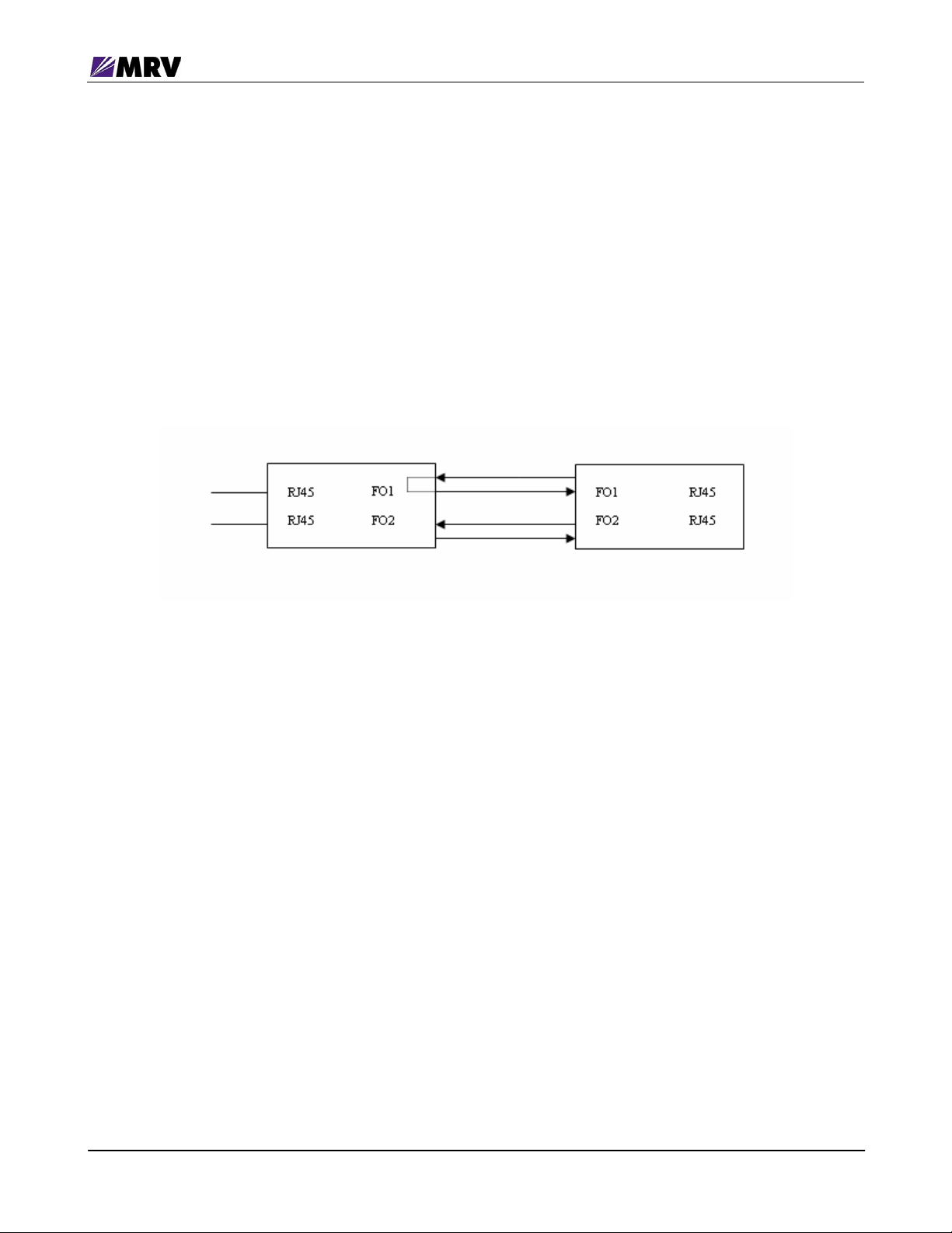
The figure below illustrates loopback with a pair of EM316SW-XY modules. In the drawing, FO1
and FO2 refer to fiber optic ports P2 and P3.
Figure 1 -- Loopback on FO1 while FO2 is in normal operation
The two loopback switches (loopback and loopback2) correlate to the two converters on the
module. “Loopback” controls port P2 and “Loopback2” controls port P3. The switch settings
apply to operation in all operational modes. In Redundant Link mode, both the loopback
switches must be set to the same position (either both ON or both OFF) for supported operation.
PN 1288003-001, Rev D2
2

Fiber Driver® EM316SW-XY
2.1.2 Link Integrity Notification (LIN)
LIN is not available in switch mode.
A single DIP switch (LIN EN) activates LIN for the entire module except in switch mode. If this
switch is OFF, then LIN cannot be activated even through software management. In the other
operational modes, ports on the EM316SW-XY are paired as converters or repeaters. LIN
applies to each port pairing with mode considerations noted in the corresponding sections. In
Redundant Link mode, changing LIN status on any port adjusts all ports (P1, P2, and P3) to the
same setting. Port P4 is disabled in this mode.
When a link fault is detected on a paired port, LIN shuts down the transmitter on the partner port
to notify connected equipment dependent the lost link. This status propagation allows switches,
routers, and other link-state dependant devices to accurately react to link conditions.
With standard LIN operation (without FEFI), digital diagnostics traps are suppressed. The LED
indicates beaconing with regular flashes while a link is down and data activity with irregular
flickers otherwise. A beaconing port is considered to have no signal.
LIN is especially valuable in fault-tolerant designs.
2.1.3 LIN with Far End Fault Indication (FEFI)
The SFP ports support FEFI, which conforms to IEEE 802.3u 100BASE-FX specifications.
When an SFP port detects a link failure on its receiver, it sends an FEFI (Far End Fault
Indication) signal to the remotely connected device as notice of a link fault. It may also receive
an FEFI signal sent from the remote link partner, which causes it to disable the paired copper
Ethernet port transmitter.
FEFI is always enabled on the EM316SW-XY, but it is used only as requested by LIN and
configured through either DIP switches (FEFI and FEFI2) or management module
administration.
In Redundant Link mode, enable both FEFI DIP switches (FEFI=ON and FEFI2=ON) to use
FEFI with LIN. This configuration provides “1:1” link protection to the redundant link. The dualhoming configuration (separate remote optical devices) is not supported.
2.1.4 Redundancy
The EM316SW-XY redundant mode (discussed in the following section) pairs the two SFP ports
(P2 and P3) as a self-healing link based on signal detection. The switch-over time when the
active fiber link fails is very short, which can allow transparent failover.
LIN disables the Ethernet port P1 only if BOTH fiber channels fail simultaneously. Port P4 is
disabled in redundant mode.
PN 1288003-001, Rev D2
3

Fiber Driver® EM316SW-XY
2.2 Modes of Operation
The EM316SW-XY supports four different operational modes.
1. Dual Repeater (Fiber and Copper)
2. Dual Converter
3. Redundant Link
4. Switch (4-Port, mixed-media)
This section describes these modes and required DIP switch settings.
Select the operational mode with the DIP switches labeled MODE1 and MODE0, switches 5 and 6
on switch block 1 nearest the front panel of the module.
Mode
Dual Repeater ON ON
DIP Switches
MODE1 MODE0
Port Grouping
Fiber Repeater: ports P2 & P3
Copper Repeater: ports P1 & P4
Dual Converter ON OFF
Redundant Link OFF ON
Mixed-Media Switch OFF OFF All ports (P1, P2, P3, P4)
Converter 1: ports P1 & P2
Converter 2: ports P3 & P4
Redundant: fiber optic ports P2 & P3
Local: copper port P1
Unused: copper port P4
PN 1288003-001, Rev D2
4
Fiber Driver® EM316SW-XY
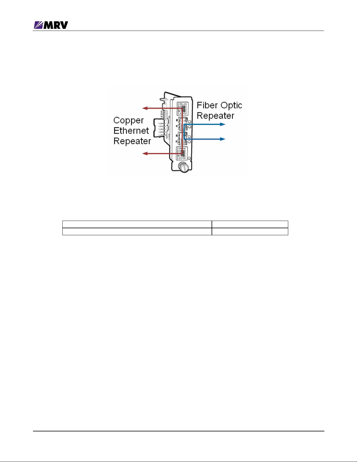
2.2.1 Dual Repeater (Fiber and Copper)
MODE1 ON
MODE0 ON
Figure 2 -- Dual Repeater Mode
In Dual Repeater mode, the module acts as a pair of repeaters.
Fiber Optic repeater between 100Base-FX ports SFP-based interfaces
Copper repeater between 10/100 Base-TX ports RJ-45 copper interfaces
The copper repeater can be used as a distance extender in a copper infrastructure to extend a
link beyond the 300 foot (100m) limit. Each RJ-45 interface supports speed and duplex
matching and automatic MDI/MDIX detection. LIN applies to this configuration, as well.
With LIN enabled, loss of link at a port receiver disables the transmitter of the paired port. There
is no beaconing on an inactive link in Dual Repeater mode.
PN 1288003-001, Rev D2
5
Fiber Driver® EM316SW-XY
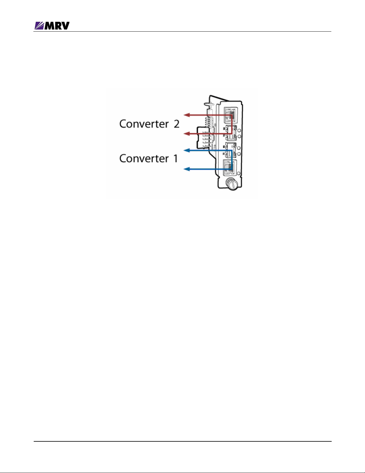
2.2.2 Dual Converter
MODE1 ON
MODE0 OFF
Figure 3 -- Dual Converter Mode
In Dual Converter mode, the module incorporates two independent “copper 10/100 to Fiber Fast
Ethernet converters” for the price of a single converter. This combination doubles the density of
a central office chassis, allowing up to 30 converters in a managed 16-slot chassis.
The first converter uses ports P1 and P2. The second converter uses ports P3 and P4.
With LIN enabled, loss of link at a port receiver disables the transmitter of the paired port.
Downstream switches, routers, and other link-state dependant devices can accurately react to
changing link conditions. This feature is especially valuable in fault-tolerant network designs.
The module supports both LIN and FEFI for link status propagation in Dual Converter mode. In
this mode, LIN offers two functional options.
1) The basic LIN (FEFI disabled) maintains backwards compatibility with all MRV Fast
Ethernet media conversion modules as well as the common Far End Fault Indication
(FEFI). The SFP transceiver beacons (transmits a periodic signal) if there is no signal
detected on its receiver. This signal notifies the other side about the detected problem.
2) A revised LIN (FEFI enabled), which uses the FEFI standard to notify the other side
about a problem in the receive fiber. Beaconing is not necessary in this case.
The revised LIN is recommended if the other side of the link supports FEFI. Use basic LIN if the
remote device does not support FEFI.
A single DIP switch controls LIN for both converters, so both will use either LIN enabled or
disabled.
PN 1288003-001, Rev D2
6
Fiber Driver® EM316SW-XY
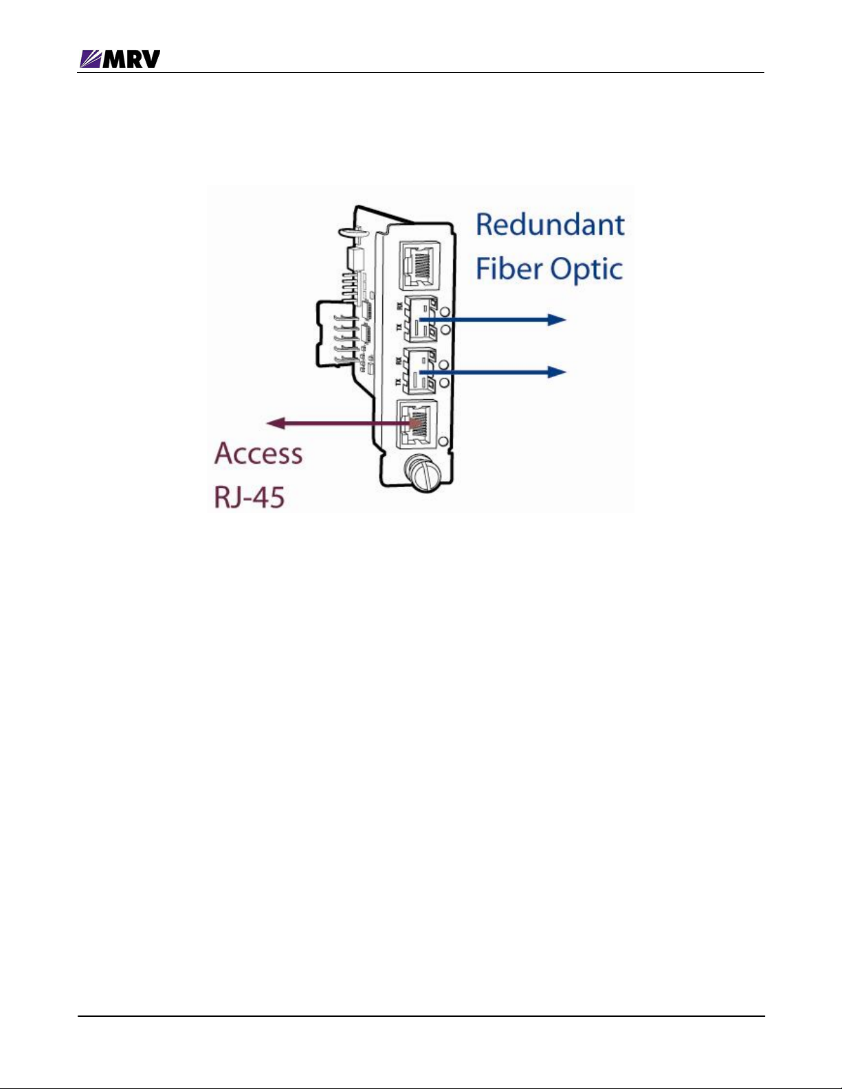
2.2.3 Redundant Link
MODE1 OFF
MODE0 ON
Figure 4 -- Redundant Link Mode
In Redundant Link mode, the module acts as a copper to redundant fiber (100Base-FX)
converter. This configuration requires optical SFPs installed in ports P2 and P3 to support a pair
of redundant fiber optic paths. Ethernet port P4 is disabled in this mode; only description
commands will have any effect on P4. The Redundant Link mode provides “1:1” link protection.
Dual-homing is not supported.
In this mode, the EM316SW-XY can pass link status with LIN or with the industry standard Far
End Fault Indication (FEFI). Implementing both tools allows for backwards compatibility with the
full set of MRV Fast Ethernet media conversion solutions while supporting standard connectivity
to any standard Fast Ethernet fiber optic port.
With LIN enabled, loss of link at BOTH fiber ports (P2 and P3) disables the transmitter of the
access (Ethernet) port (P1). If one fiber optic channel fails while the other fiber optic channel is
operational, LIN does not interrupt the data. Downstream switches, routers, and other link-state
dependant devices can accurately react to changing link conditions. This feature is especially
valuable in fault-tolerant network designs. Set both DIP switches (FEFI and FEFI2) ON to
enable FEFI with LIN in Redundant Link mode.
The “select-link” command is enabled for ports P2 and P3 in Redundant Link mode to force a
port to active if it has an available link. There is no default or preferred port, so the first link
established becomes active. The “shutdown” command is not available for redundant ports P2
and P3.
PN 1288003-001, Rev D2
7
Fiber Driver® EM316SW-XY
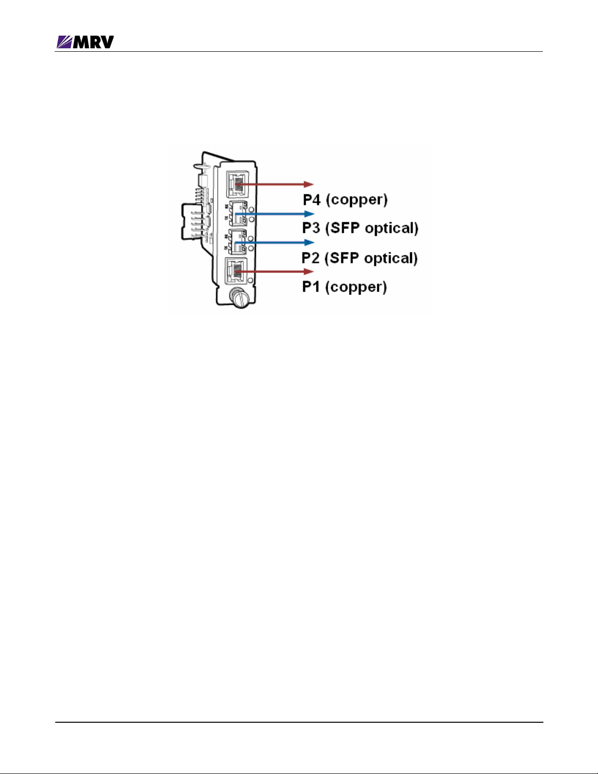
2.2.4 Mixed-Media Switch (4-Port)
MODE1 OFF
MODE0 OFF
Figure 5 -- Switching Mode
In Switch mode, the module acts a mixed-media Ethernet Switch with two 10/100Base-TX
copper interfaces and two fiber-optic SFP-based 100 Base-FX interfaces.
The mixed-media switch allows copper Ethernet traffic access to a linear fiber-optic Ethernet
network.
LIN is not supported in this mode.
PN 1288003-001, Rev D2
8
Fiber Driver® EM316SW-XY
3 Preparation and Installation
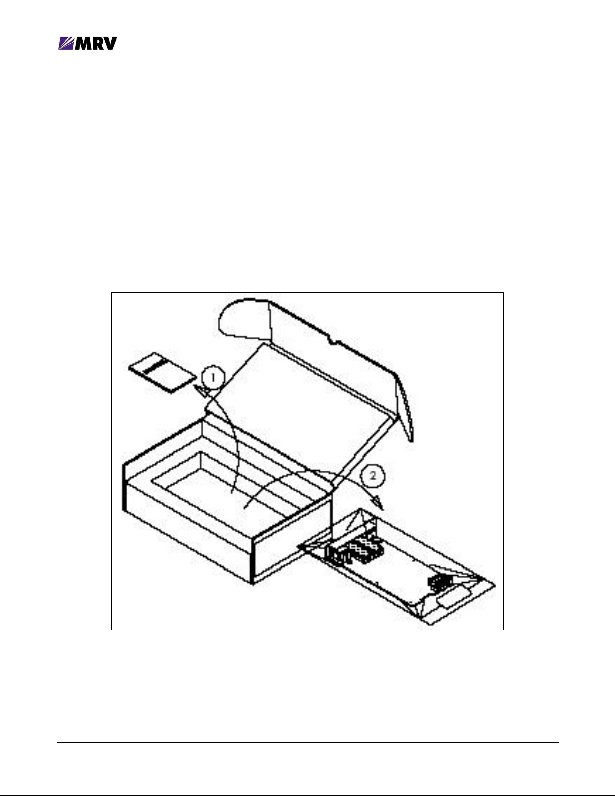
3.1 Unpacking the Fiber Driver Module
Step 1. Open the cardboard box.
Step 2. Remove the static bag containing the module.
Step 3. Check for additional or loose accessories in the box.
Parts may move under the module packing tray during shipment.
In the unlikely event that a part is missing from the contents, contact your authorized
MRV dealer or representative. If product return becomes necessary, ship the unit in its
original packaging and container.
PN 1288003-001, Rev D2
Figure 6 -- Unpacking
9
Fiber Driver® EM316SW-XY
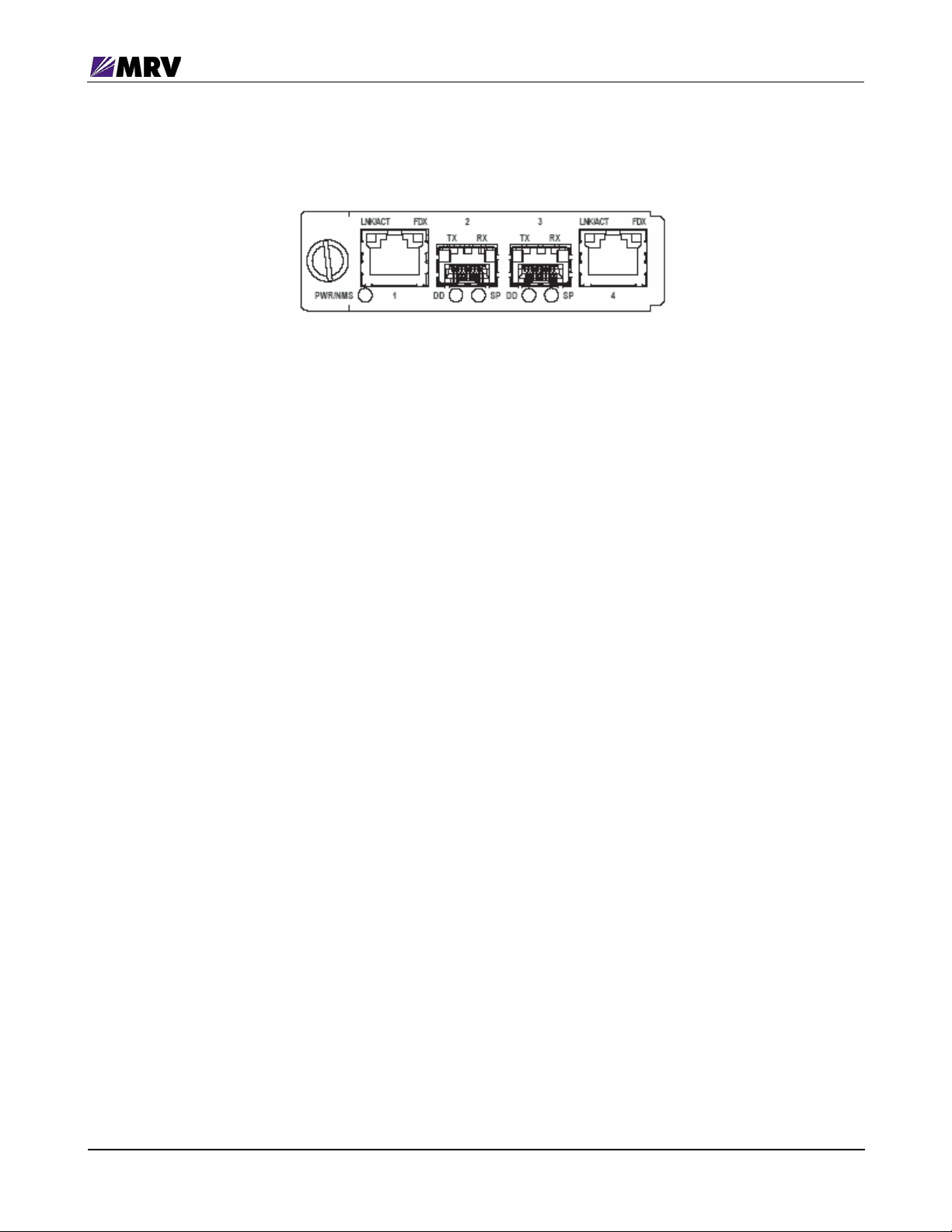
3.2 Front Panel Description
Figure 7 -- EM316SW-XY front panel
The EM316SW-XY module is equipped with the following interfaces.
Port 1 (1): 10/100 Base-T UTP RJ-45
Port 2 (2): 100 Base-FX, SFP- Port
Port 3 (3): 100 Base-FX, SFP Port
Port 4 (4): 10/100 Base-T UTP RJ-45
3.2.1 Distances
Maximum distance for SFP ports is SFP dependent.
Maximum distance for ports 1 and 4 (UTP) 100 meters.
3.2.2 SFP Ports
Ports 2 and 3 (SFP) can be configured as redundant link ports (Redundant Link Mode) or
individually operated (Dual Converter or Switching Mode)
3.2.3 LED Definitions
PWR/NMS: Indicates module power and loopback mode status of at least one port.
P1 UTP: LNK/ACT blinking on link and activity
P2 DD: Digital Diagnostic indicator for the SFP inserted in Port 2.
P2 SP: Indicates presence of SFP and presence of link and activity.
P3 DD: Digital Diagnostic indicator for the SFP inserted in Port 3.
FDX is lit when full duplex link is configured or established.
P3 SP: Indicates presence of SFP and presence of link and activity.
P4 UTP: LNK/ACT blinking on link and activity
FDX is lit when full duplex link is configured or established.
PN 1288003-001, Rev D2
10

Fiber Driver® EM316SW-XY
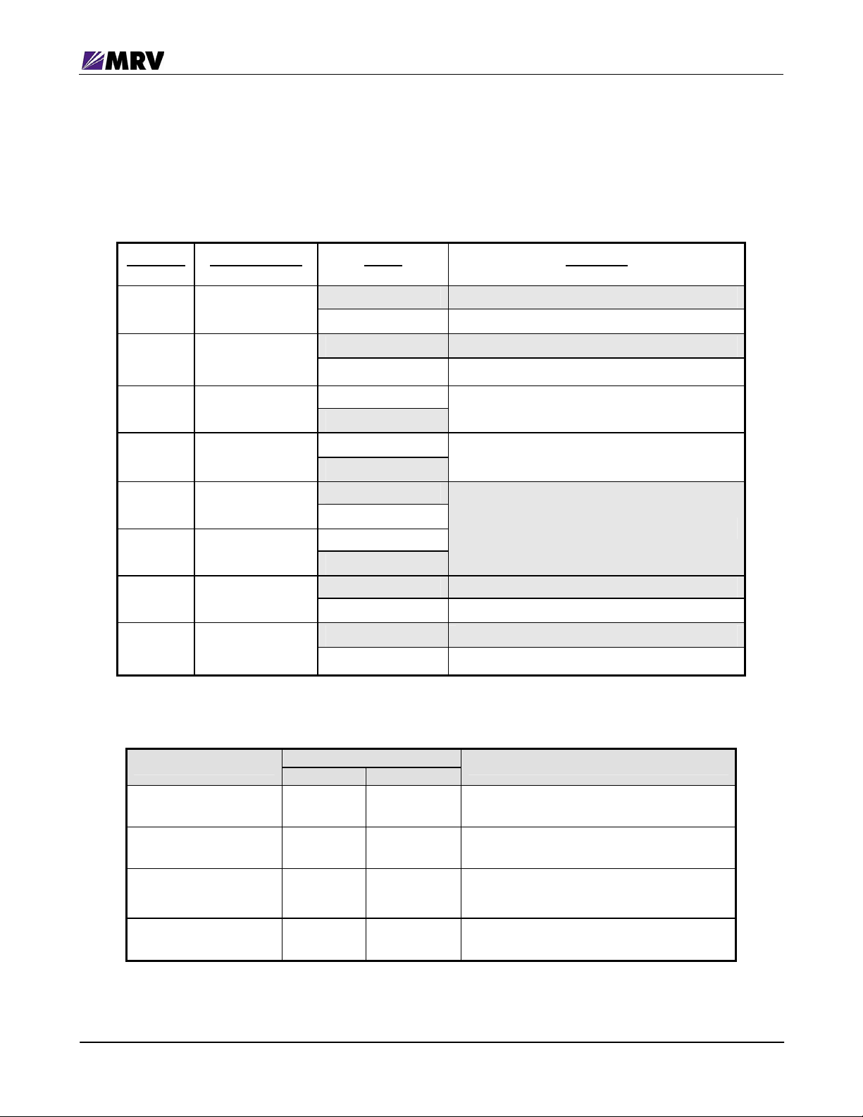
3.2.4 LED Display Information
LED Color Solid or Blink Explanation
PWR/NMS
green solid Power OK
green blink At least one port in loopback
P1 UTP
LNK/ACT OFF n/a No link detected
amber solid 10 Mbps link
green solid 100 Mbps link
amber blink Data flow with 10Base-T protocol
green blink Data flow with 100Base-T protocol
FDX OFF n/a Half duplex
green solid Full duplex
P2 SFP
DD OFF n/a No SFP with DD support detected
green solid No alarm
amber solid Alarm
SP green solid SFP present and link present
amber solid SFP inserted, no link
green/amber blink Link present and activity
P3 SFP
DD OFF n/a No SFP with DD support detected
green solid No alarm
amber solid Alarm
SP green solid Link present
amber solid SFP inserted, no link
green/amber blink Link present, activity
P4 UTP
LNK/ACT OFF n/a No link detected
amber solid 10 Mbps link
green solid 100 Mbps link
amber blink 10 Mbps Data flow
green blink 100 Mbps Data flow
FDX OFF n/a Half duplex
green solid Full duplex
OFF n/a No power to unit
Figure 8 -- EM316SW-XY front panel
PN 1288003-001, Rev D2
11

Fiber Driver® EM316SW-XY
3.3 DIP Switches
The default configuration is established by the firmware preloaded onto the module. The
EM316SW-XY is configured at the factory to work “out of the box” in “Dual Converter” mode with
management enabled.
Use the module in pairs to operate the EM316SW-XY in unmanaged mode. Select the
functional modes with DIP switches MODE1 and MODE0 on switch block 1 (nearest the front
panel).
In addition to the four operational modes, LIN, Auto-MDI, and Loopback may also be configured.
3.3.1 Block Locations
PN 1288003-001, Rev D2
Figure 9 -- DIP switch locations
12
Fiber Driver® EM316SW-XY
3.3.2 Switch Functions and Default Settings
The switch block number is not sequential on the module. Carefully verify the switch block
number and placement before changing switch settings.
Switch Block 1*
DIP Switch DIP Switch Name Setting Description
1
2
3
4
5
6
7
8
MANG EN
LIN EN
AGING F
MODE1
MODE0
ANEG
ANEG2
ON (up) Control by NM is enable
OFF (down) Control be NM is disable
ON (up) LIN enable
OFF (down) LIN disable
ON (up)
OFF (down)
ON (up)
OFF (down)
ON (up)
OFF (down)
ON (up)
OFF (down)
ON (up) P1 Auto Negotiation is enable
OFF (down) P1 Auto Negotiation is disable
ON (up) P4 Auto Negotiation is enable
OFF (down) P4 Auto Negotiation is disable
SW1-5, SW1-6 – Operational Modes
Mode
Dual Repeater ON ON
DIP Switches
MODE1 MODE0
NOT USED
NOT USED
See table below
Port Grouping
Fiber Repeater: ports P2 & P3
Copper Repeater: ports P1 & P4
Dual Converter
(default mode)
Redundant Link OFF ON
Mixed-Media Switch OFF OFF All ports (P1, P2, P3, P4)
PN 1288003-001, Rev D2
ON OFF
Converter 1: ports P1 & P2
Converter 2: ports P3 & P4
Redundant: fiber optic ports P2 & P3
Local: copper port P1
Unused: copper port P4
13

Fiber Driver® EM316SW-XY
Switch Block 2* (SW2)
Setting
DIP Switch DIP Switch Name
Bold = Defaults
Description
1 FAST
2 FULL
3 AMDI
4 LPBK
5 FAST2
6 FULL2
7 AMDI2
8 LPBK2
ON (up) P1 Forced 100Base-T if ANEG is off
OFF (down) P1 Forced 10Base-TX if ANEG is off
ON (up) P1 Forced Full-Duplex if ANEG is off or failed
OFF (down) P1 Forced Half-Duplex if ANEG is off or failed
ON (up) P1 Auto MDI is enabled
OFF (down) P1 Auto MDI is disabled if ANEG is off
On (up) P2 loopback is enabled
OFF (down) P2 loopback is disabled
ON (up) P4 Forced 100Base-T if ANEG2 is off
OFF (down) P4 Forced 10Base-TX if ANEG2 is off
ON (up) P4 Forced Full-Duplex if ANEG2 is off or failed
OFF (down) P4 Forced Half-Duplex if ANEG2 is off or failed
ON (up) P4 Auto MDI is enabled
OFF (down) P4 Auto MDI is disabled if ANEG2 is off
ON (up) P3 loopback is enabled
OFF (down) P3 loopback is disabled
* Shaded and bold describe factory default settings
PN 1288003-001, Rev D2
14

Fiber Driver® EM316SW-XY
Switch Block 3* (SW3)
DIP Switch DIP Switch Name Setting Description
1 FEFI
2 FEFI2
3
4
5
6
7
8
ON (up) P2 Far End fault Indication is used in LIN
OFF (down) Far End Fault Indication is not used in LIN
ON (up) P3 Far End fault Indication is used in LIN
OFF (down) Far End Fault Indication is not used in LIN
ON (up)
OFF (down)
ON (up)
OFF (down)
ON (up)
OFF (down)
ON (up)
OFF (down)
ON (up)
OFF (down)
ON (up)
OFF (down)
NOT USED
NOT USED
NOT USED
NOT USED
NOT USED
NOT USED
* Shaded and bold describe factory default settings
PN 1288003-001, Rev D2
15
 Loading...