

MRV Communications EM316EDFA-LPR, EM316EDFA-BR User Manual
EM316EDFA-BR
Erbium Doped Fiber Amplifier Booster
EM316EDFA-LPR
Erbium Doped Fiber Inline Pre-Amplifier
User Guide
1294008-001
Revision D2
January 28, 2008

Fiber Driver® EM316EDFA User Guide
Table of Contents
1 Preliminary Considerations ..............................................................iii
1.1 Trademarks...................................................................................................................................................iii
1.2 Copyright.......................................................................................................................................................iii
1.3 Customer Support.........................................................................................................................................iii
1.4 Compliance ...................................................................................................................................................iv
1.5 General Safety .............................................................................................................................................. v
1.5.1 Cautions and Warnings ......................................................................................................................... v
1.5.2 Laser Safety........................................................................................................................................... v
1.5.3 Laser Device Classifications..................................................................................................................vi
1.5.4 Static Electricity ....................................................................................................................................vii
1.5.5 Workplace Preparation ......................................................................................................................... vii
1.6 About This Manual ...................................................................................................................................... viii
1.7 Latest Revision and Related Documents.................................................................................................... viii
2 Introduction to EM316EDFA Optical Amplifiers................................ 1
2.1 Features........................................................................................................................................................ 2
2.1.1 EM316EDFA-BR / EM316EDFA-LPR Monitored Parameters .............................................................. 2
2.1.2 EDFA Control Inputs.............................................................................................................................. 2
2.1.3 EDFA Alarm Outputs ............................................................................................................................. 2
3 Preparation and Installation.............................................................. 3
3.1 Unpacking the Fiber Driver Module .............................................................................................................. 3
3.2 Front Panel.................................................................................................................................................... 4
3.3 LEDs ............................................................................................................................................................. 4
3.4 DIP Switches................................................................................................................................................. 4
3.5 Module Installation ........................................................................................................................................ 5
4 EDFA Features................................................................................. 7
4.1 Network Management Control and Monitoring ............................................................................................. 7
4.1.1 Management Control from the Network ................................................................................................ 8
4.1.2 EM316EDFA Alarm Output Pins ........................................................................................................... 8
4.1.3 Operating Parameters ........................................................................................................................... 8
5 Module Management........................................................................ 9
5.1 Serial Console Interface.............................................................................................................................. 10
5.2 EM316LNXNM-OT Command Line Interface (CLI) .................................................................................... 11
5.2.1 EM316LNXNM-OT Boot and CLI Login .............................................................................................. 12
5.2.2 CLI Navigation ..................................................................................................................................... 13
5.2.3 Login Context Commands and Examples ........................................................................................... 14
5.2.3.1 “show version”..........................................................................................................14
5.2.3.2 “show log” ..................................................................................................................14
5.2.3.3 “show running-config”...........................................................................................15
5.2.3.4 “show startup-config”...........................................................................................16
5.2.3.5 Configuring System Parameters ...................................................................................17
P/N 1294008-001 Rev D2 i

Fiber Driver® EM316EDFA User Guide
5.2.4 Chassis Context .................................................................................................................................. 18
5.2.4.1 “show”...........................................................................................................................18
5.2.4.2 Other Commands..........................................................................................................19
5.2.5 Slot Context Commands and Examples.............................................................................................. 20
5.2.5.1 “?” .................................................................................................................................21
5.2.5.2 “list”...........................................................................................................................22
5.2.5.3 “show”...........................................................................................................................23
5.2.6 Port Context Commands and Examples ............................................................................................. 26
5.2.6.1 “?” .................................................................................................................................27
5.2.6.2 “list”...........................................................................................................................29
5.2.6.3 “show”...........................................................................................................................30
5.2.6.4 “port description” .................................................................................................31
5.2.7 Displaying and Saving System Parameters ........................................................................................ 32
5.2.8 Restoring Default Parameters ............................................................................................................. 33
6 Appendix......................................................................................... 34
6.1 Technical Specifications ............................................................................................................................. 34
6.2 Troubleshooting .......................................................................................................................................... 34
Table of Figures
Figure 1 -- EM316EDFA optical amplifier applications ......................................................................................... 1
Figure 2 -- Unpacking............................................................................................................................................ 3
Figure 3 -- EM316EM316EDFA-BR / EM316EDFA-LPR Front Panel.................................................................. 4
Figure 4 -- Remove the required blank panels...................................................................................................... 5
Figure 5 -- Module installation (not all chassis are shown) ................................................................................... 6
Figure 6 -- Fiber Driver module installed in a powered chassis............................................................................ 6
Figure 7 -- EM316LNXNM-OT general commands for EDFA modules .............................................................. 11
Figure 8 – EM316LNXNM-OT slot context commands for EDFA modules ........................................................ 20
Figure 9 – EM316LNXNM-OT port context commands for EDFA modules........................................................ 26
P/N 1294008-001 Rev D2 ii

Fiber Driver® EM316EDFA User Guide
1 Preliminary Considerations
1.1 Trademarks
All trademarks are the property of their respective holders.
1.2 Copyright
MRV Communications reserves the right to change technical specifications or documentation in
order to improve reliability, function, or design. Exercise discretion in using this document. The user
assumes sole responsibility for applying the information supplied herein.
Copyright © 2007 by MRV Communications. All rights reserved.
1.3 Customer Support
Before contacting customer support, look for software updates, technical specifications, and
frequently asked questions (FAQ) online at the MRV support website:
The website includes information regarding software updates, technical specifications, and
frequently asked questions (FAQ) as well as contact information.
Contact help online by sending email to
http://service.mrv.com/support/forms/supportcall.cfm
For direct MRV customer support by telephone, call your local sales representative, system
engineer, or one of the following numbers.
MRV Americas
(US, Canada, and Latin America)
support@mrv.com or through the website request link at
+1-800-435-7997
+1-978-952-4888
http://service.mrv.com.
MRV Europe +49-6105-2070
MRV International +972-4-993-6200
Include the following important information when opening a support case.
• Site ID or company name
• Contact information
• Model or product name
• Serial number
• Top assembly revision (see label on board)
• Brief problem or question including a description of the host network environment
• Attenuation data for applicable high-speed fiber links
• Urgency of the issue
P/N 1294008-001 Rev D2 iii

Fiber Driver® EM316EDFA User Guide
1.4 Compliance
Contact your sales representative for more regulatory compliance information regarding specific
MRV products or product families.
Fiber Driver Chassis
FCC Part 15 (Class A); IC (Class A); EMC Directive: Emission (Class A) and Immunity; LVD
Directive: Electrical Safety; CE Marking; TUV CUE Mark (Canada, USA, EU); GOST; RoHS
Directive, WEEE Directive: Wheelie Bin Mark; ETSI, NEBS, C-Tick
Fiber Driver Modules
FCC Part 15 (Class A); IC (Class A); EMC Directive: Emission (Class A) and Immunity; LVD
Directive: Electrical Safety; RoHS Directive, WEEE Directive: Wheelie Bin Mark; ETSI
Optical and Copper Transceivers
FCC Part 15 (Class A); IC (Class A); EMC Directive: Emission (Class A) and Immunity; LVD
Directive: Electrical Safety; CE Marking; TUV; UL, CSA, RoHS Directive, ETSI, NEBS, compliant
with EN 60825-1/A1:2002 Safety of Laser Products
P/N 1294008-001 Rev D2 iv
Fiber Driver® EM316EDFA User Guide
1.5 General Safety
1.5.1 Cautions and Warnings
Disconnect all power from electronic devices before servicing. Some equipment may have
multiple power cords requiring disconnection.
1.5.2 Laser Safety
WARNING: Fiber optic equipment may emit laser or infrared light that can injure your
eyes. Never look into an optical fiber or connector port. Always assume that fiber optic
cables are connected to a laser light source.
CAUTION: Do not install or terminate fibers when a laser may be active.
WARNING: Never look directly into a live optical fiber. Always wear appropriate laser
safety glasses when working with open fiber cables that might be connected to an
operational laser transmitter. Direct open fibers ends away from faces.
CAUTION: Use of controls or adjustments or performing procedures other than those
specified herein may result in hazardous radiation exposure.
If a fiber optic laser device output is recognized as a higher than Class 1 product (Class 1M, for
example), the device is evaluated, labeled, and certified by TUV. Class 1 and 1M outputs are
not considered hazardous, but laser safety practices should always be observed.
A fiber optic transceiver emits either single-mode or multi-mode light into a fiber optic strand.
Take the following precautions when handling optical fibers.
• Wear safety glasses when you install optical fibers.
• Be aware of the risk of laser radiation exposure.
• Always assume that fiber optic cables are active because transmitted light is invisible to
the human eye.
• Never look directly into a beam (T
light can damage your eyes.
• Place optical fibers in a safe location during installation.
• Protect optical fiber connectors with clean dust caps for safety and sanitation.
• Follow the manufacturer instructions when using optical test equipment.
part of a transmitter) or open fiber ends. The invisible
X
P/N 1294008-001 Rev D2 v
Fiber Driver® EM316EDFA User Guide
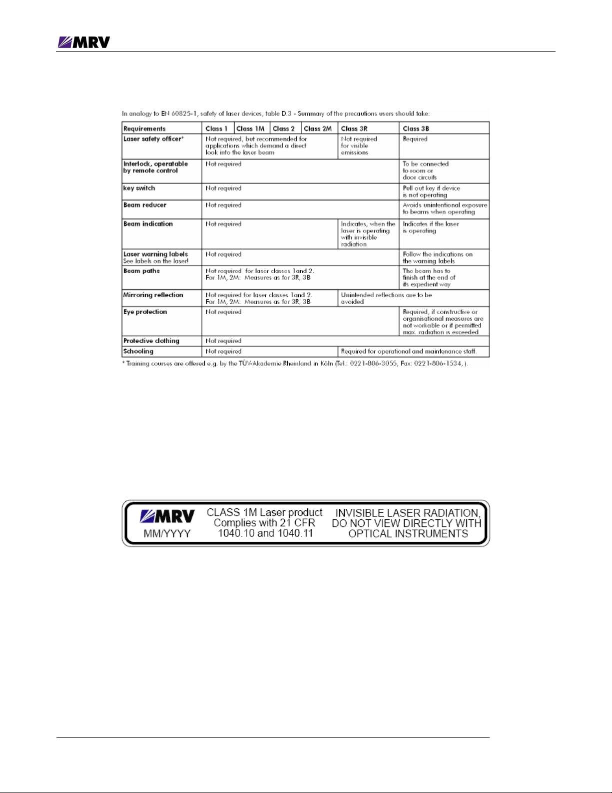
1.5.3 Laser Device Classifications
Laser devices of class 1M, class 2, class 2M and class 3R
Precautionary measures are only necessary to avoid a permanent direct looking into the laser
beam; for classes 2 and 2M is a momentary (0.25 sec.) irradiation in a wave length range
between 400 nm and 700 nm, as it may occur when you accidentally look into the beam, not
considered to be dangerous. However, you should not level the laser beam intentionally at
people. The use of optical aids (e.g. binoculars) together with laser devices of the classes 1M,
class 2M and class 3R may increase the danger for the eyes
P/N 1294008-001 Rev D2 vi

Fiber Driver® EM316EDFA User Guide
1.5.4 Static Electricity
Eliminate static electricity in the workplace by grounding operators, equipment, and devices
including components and computer boards. Grounding prevents static charge buildup and
electrostatic potential differences. Transporting products in special electrostatic shielding
packages reduces electrical field damage potential.
1.5.5 Workplace Preparation
A safe and effective workplace provides the following items.
• ESD protective clothing/smocks: Street clothing must not come in contact with components
or computer boards since the various materials in clothing can generate high static charges.
ESD protective smocks, manufactured with conductive fibers, are recommended.
• Electrostatic shielding containers or totes: These containers (bags, boxes, etc.) are made of
specially formulated materials, which protect sensitive devices during transport and storage.
• Antistatic or dissipative carriers: These provide ESD protection during component movement
in the manufacturing process. It must be noted that antistatic materials alone will not provide
complete protection. They must be used in conjunction with other methods such as totes or
electrostatic shielding bags.
• Dissipative tablemat: The mat should provide a controlled discharge of static voltages and
must be grounded. The surface resistance is designed such that sliding a computer board or
component across its surface will not generate more than 100 V.
• Operator grounding: Keep a wrist strap or ESD cuff in constant contact with bare skin with a
cable for attaching it to the ESD ground. The wrist strap drains off the static charge of the
operator. The wrist strap cord has a current-limiting resistor for personnel safety. Wrist straps
must be tested frequently to ensure that they are undamaged and operating correctly. Use
special grounding heel straps or shoes when a wrist strap is impractical. These items are
effective only when used in conjunction with a dissipative floor.
• ESD protective floor or mat: The mat must be grounded through a current-limiting resistor.
The floor or mat dissipates the static charge of personnel approaching the workbench.
Special conductive tile or floor treatment can be used when mats are not practical or cause a
safety hazard. Chairs should be conductive or grounded to the floor with a drag chain.
P/N 1294008-001 Rev D2 vii

Fiber Driver® EM316EDFA User Guide
1.6 About This Manual
Document Number: P/N 1294008-001 Rev D2
Document: EM316EDFA-BR / EM316EDFA-LPR User Guide
Release Date: January 28, 2008, 4:26:01 PM
1.7 Latest Revision and Related Documents
The latest revision of MRV documents may be found at:
Release Notes for Fiber Driver modules are produced as required.
EM316LNXNM-OT User Guide: Software-generated manual for EM316LNXNM-OT Network
Management module usage describing the command line interface (CLI) and commands.
MegaVision User Manual: Graphical network management system for Fiber Driver modules and
other SNMP manageable products and IP devices using MRV Communication’s MegaVision Pro®
Network Management System.
http://www.mrv.com
P/N 1294008-001 Rev D2 viii
Fiber Driver® EM316EDFA User Guide
2 Introduction to EM316EDFA Optical Amplifiers
The fiber optic amplifier module is used to increase an optical signal for extended range or clarity
without electrical conversion circuitry. The MRV EM316EDFA modules boost an optical input up to 20
decibels. The amplifier also has a bandwidth of 40 nm, making it suitable for use in wavelength
division multiplexing (WDM) applications as an optical spectral amplifier. The module may be
controlled from the network through the MRV EM316LNXNM-OT Network Manager Module.
Optical amplifiers operate in different modes, depending upon their position in the optical link. The
EM316EDFA is available in two configurations to fill the necessary roles in your network.
EM316EDFA-BR
EM316EDFA-LPR
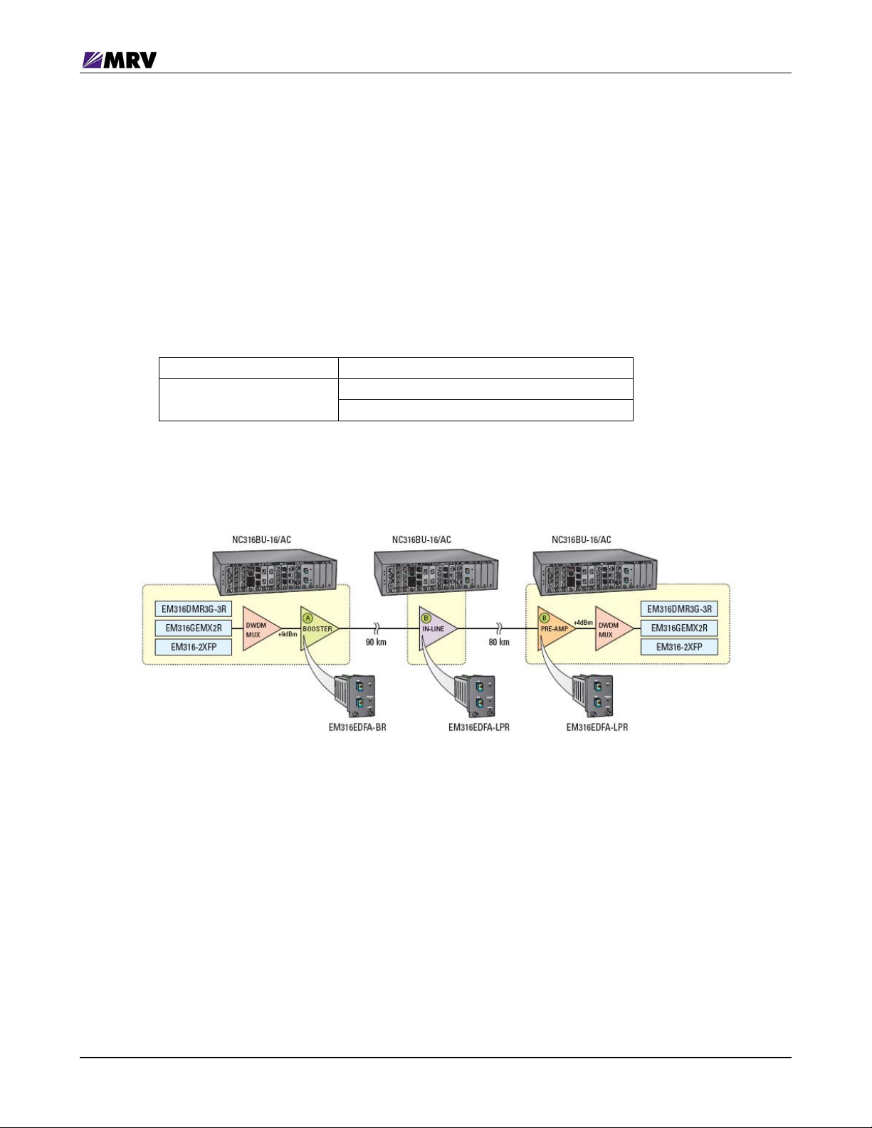
The example below illustrates how the EM316EDFA optical amplifiers fit into an optical link.
C-band optical amplifier booster
C-band in-line optical amplifier
C-band pre-amplifier
Figure 1 -- EM316EDFA optical amplifier applications
EM316EDFA-BR is used as long haul booster module in combination with an EM316EDFA-LPR inline
pre-amplifier.
P/N 1294008-001 Rev D2 1

Fiber Driver® EM316EDFA User Guide
2.1 Features
The EM316EDFA board can run in standalone mode without any input from a management
module. The EM316EDFA analog input power determines the output power because the module
runs at a fixed gain.
EM316EDFA status is reported through SNMP through a network management module as well as
by LEDs on the front panel.
The green “SD” LED on the front panel indicates input greater than the thresholds corresponding to
the EDFA module type, as indicated in the table below.
EM316EDFA-BR -8 dBm
EM316EDFA-LPR -30 dBm
A green LED at front panel (Optical Output) indicates output power greater than -10 dBm.
The module temperature is measured from 0
against excessive heat, the laser shuts down when measured temperature reaches 70
2.1.1 EM316EDFA-BR / EM316EDFA-LPR Monitored Parameters
• Input power and output power readings
• Output gain reading
• Case temperature reading
• Amplifier status reading
• Alarm status
o case temperature
o loss of input power
o loss of output power
2.1.2 EDFA Control Inputs
• Software reset
• Output power mute
2.1.3 EDFA Alarm Outputs
• Case temperature
• Loss of input
• Loss of output
o
C to 70o C and reported to management. To protect
o
C.
P/N 1294008-001 Rev D2 2
Fiber Driver® EM316EDFA User Guide
3 Preparation and Installation
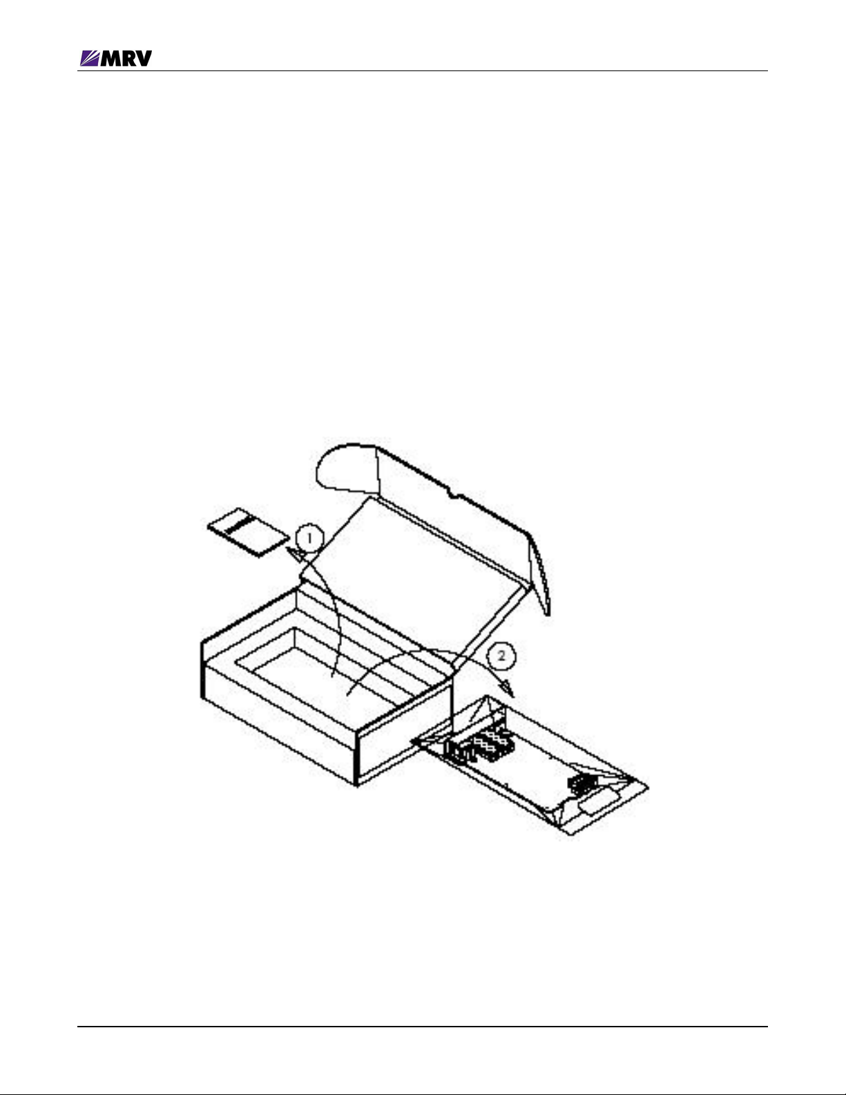
3.1 Unpacking the Fiber Driver Module
Follow these steps with reference to the figure below.
Step 1. Open the cardboard box
Step 2. Remove the static bag containing the device.
Step 3. Check for additional accessories in the box that may move beneath the module tray
during transit.
In the unlikely event that any package content is missing, contact an authorized MRV dealer or
representative. If it becomes necessary to return the shipment, repackage the unit in its original
box.
Figure 2 -- Unpacking
P/N 1294008-001 Rev D2 3

Fiber Driver® EM316EDFA User Guide
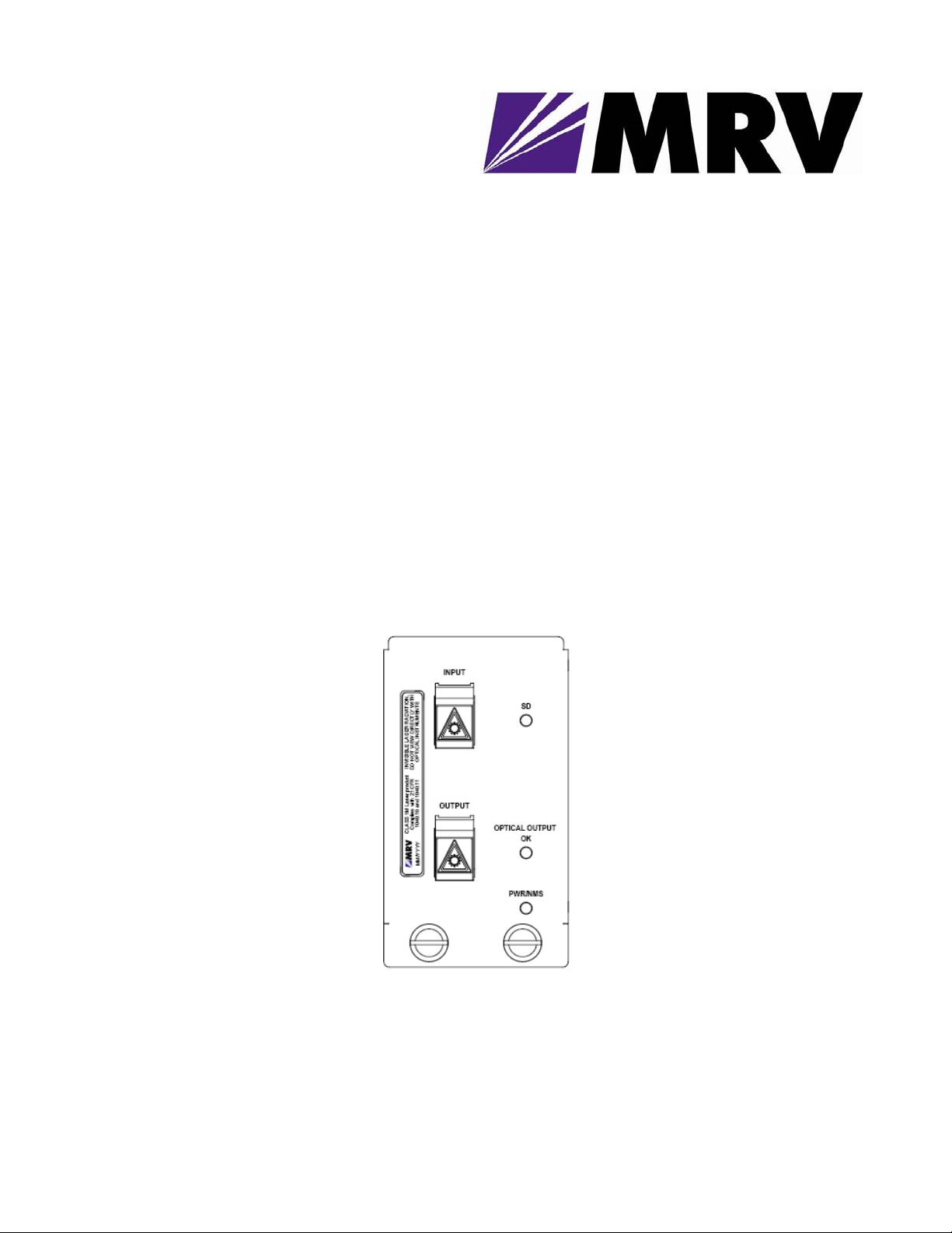
3.2 Front Panel
Figure 3 -- EM316EM316EDFA-BR / EM316EDFA-LPR Front Panel
3.3 LEDs
PWR/NMS Power
SD Input Optical Power
OPTICAL OUTPUT OK
Output Optical Power
On – DC +5V power is applied to the card
On – Input signal greater than the input threshold
setting
On – Output power is greater than -2 dBm, for apc
mode or -10 dBm for agc mode
3.4 DIP Switches
The EM316EDFA-BR is pre-configured in booster mode. There are no user-selectable switches.
The EM316EDFA-LPR is pre-configured in inline pre-amplifier mode. There are no user-selectable
switches to operate either inline or as a pre-amplifier.
The DIP switch block at the underside of the module has six switches. Only switch 6 affects
operation of the amplifier module. Use switch 6 to enable or disable network management.
Switch # Function Setting
1-5 N/A Reserved
6 Management Enable Default: ON = enable management
P/N 1294008-001 Rev D2 4
Fiber Driver® EM316EDFA User Guide
3.5 Module Installation
EM316xx cards are hot-swappable in a powered Fiber Driver chassis. Install the EM316xx module
by aligning the edge of the card with the rail of the chassis slot. Hand-tighten the thumb screw. Do
not over-tighten.
The thumb screw is on the left when installed in the BU-1, BU-2, BU-3, and BU-4 chassis. The
thumb screw is on the bottom when installed in the BU-16 chassis.
3.5.1.1.1 Tools
• 6-inch Phillips #1 screwdriver (for some module screws)
• 6-inch flat-tip 5.0 screwdriver
3.5.1.1.2 Procedure
Follow all guidelines to eliminate static electricity while handling the module and other electronic
devices. Refer to the front of this manual for some safety suggestions.
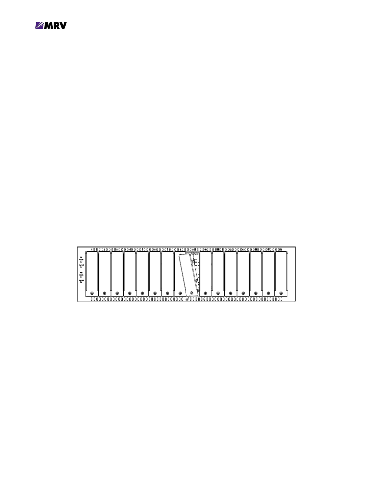
Step 1 Remove the blank panel or old module from the target chassis slot. Unfasten the
mounting screws with a 6-inch Phillips screwdriver, or disengage any thumb screws by hand.
Figure 4 -- Remove the required blank panels
To comply with FCC regulations and for optimal cooling air flow, a cover panel or a module must
cover every chassis slot. To limit external signals, no chassis slot should remain open when the
unit is operational. Secure modules and panels with appropriate screws for grounding and
further compliance.
P/N 1294008-001 Rev D2 5
 Loading...