

MRV Communications EM316-2SFP User Manual
EM316-2SFP
Transparent SFP-to-SFP Converter
With EM316NM or EM316LNXNM-OT Management
User Guide
PN 1259003-001
Revision C3
October 30, 2007

EM316-2SFP User Guide
Table of Contents
1 Preliminary Considerations.............................................................................................................iv
1.1 Trademarks..................................................................................................................................iv
1.2 Copyright .....................................................................................................................................iv
1.3 Customer Support........................................................................................................................ iv
1.4 MRV Regulatory Compliance .......................................................................................................v
1.5 General Safety.............................................................................................................................vi
1.5.1 Cautions and Warnings ........................................................................................................vi
1.5.2 Laser Safety.......................................................................................................................... vi
1.5.3 Static Electricity ................................................................................................................... vii
1.5.4 Workplace Preparation ........................................................................................................ vii
1.6 Specific Document Information.................................................................................................. viii
1.7 Latest Revision and Related Documents................................................................................... viii
1.8 EM316NM and EM316NM-5 References .................................................................................. viii
2 Product Overview..............................................................................................................................1
2.1 Management features...................................................................................................................1
2.1.1 LIN .........................................................................................................................................1
2.1.2 Loopback ...............................................................................................................................2
3 Preparation and Installation .............................................................................................................3
3.1 Unpacking the Fiber Driver Module ..............................................................................................3
3.2 Front Panel Description ................................................................................................................4
3.2.1 LED Display Information ........................................................................................................4
3.3 DIP Switch Configuration..............................................................................................................5
3.4 Module Installation........................................................................................................................6
3.5 Small Form Pluggables (SFP): Handling and Installation.............................................................8
3.5.1 Cleaning Fibers......................................................................................................................8
3.5.1.1 Cleaning Supplies...........................................................................................................8
3.5.1.2 Cleaning Procedure: .......................................................................................................8
3.5.2 Working with SFPs ................................................................................................................9
3.5.2.1 Cleaning SFPs ................................................................................................................9
3.5.2.2 Mylar Tab SFP Modules ...............................................................................................10
3.5.2.3 Actuator/Button SFP Modules.......................................................................................11
3.5.2.4 Inserting an Actuator/Button SFP Module.....................................................................11
3.5.2.5 Bale Clasp SFP Module................................................................................................12
P/N 1259003-001 Rev C3 i

EM316-2SFP User Guide
4 Module Management.......................................................................................................................13
4.1 Remote Command Line Interface (CLI) Setup ...........................................................................14
4.2 Serial Command Line Interface (CLI) Setup...............................................................................14
4.2.1 EM316NM Serial Console Setup .........................................................................................14
4.2.2 EM316LNXNM-OT Serial Console Setup............................................................................14
4.3 EM316NM[-5] Command Line Interface (CLI) ............................................................................15
4.4 EM316LNXNM-OT Command Line Interface (CLI) ....................................................................18
4.4.1 EM316LNXNM-OT Boot and CLI Login...............................................................................19
4.4.2 CLI Navigation .....................................................................................................................20
4.4.3 Login Context Commands and Examples............................................................................21
4.4.3.1 “show version”..........................................................................................................21
4.4.3.2 “show log” ..................................................................................................................21
4.4.3.3 “show running-config”...........................................................................................22
4.4.3.4 “show startup-config”...........................................................................................23
4.4.4 Configuring System Parameters..........................................................................................24
4.4.5 Chassis Context...................................................................................................................25
4.4.5.1 Chassis Context – “show”.............................................................................................25
4.4.5.2 Displaying and Saving System Parameters..................................................................26
4.4.5.3 Restoring Default Parameters.......................................................................................27
4.4.5.4 Chassis Context – Other Commands ...........................................................................28
4.4.6 Slot Context Commands and Examples ..............................................................................29
4.4.6.1 “?” .................................................................................................................................30
4.4.6.2 “list”...........................................................................................................................31
4.4.6.3 “show”...........................................................................................................................32
4.4.6.4 “show digital-diagnostics”................................................................................34
4.4.7 Port Context Commands and Examples..............................................................................35
4.4.7.1 “?” .................................................................................................................................35
4.4.7.2 “list”...........................................................................................................................37
4.4.7.3 “show”...........................................................................................................................38
4.4.7.4 Port Description ............................................................................................................39
4.4.7.5 “show defaults” .......................................................................................................40
4.4.7.6 “show config”............................................................................................................40
4.4.7.7 Loopback ......................................................................................................................41
4.4.7.8 LIN ................................................................................................................................41
4.4.7.9 Shutdown ......................................................................................................................42
5 Appendix ..........................................................................................................................................43
5.1 Technical Specifications .............................................................................................................43
5.2 Supported Data Rates ................................................................................................................43
5.3 Firmware Download....................................................................................................................43
5.4 Troubleshooting ..........................................................................................................................44
P/N 1259003-001 Rev C3 ii

EM316-2SFP User Guide
Table of Figures
Figure 1 -- Unpacking ...........................................................................................................................3
Figure 2 -- Front Panel Schematic of the EM316-2SFP .......................................................................4
Figure 3 -- LED Legend ........................................................................................................................4
Figure 4 – DIP switch settings ..............................................................................................................5
Figure 5 -- DIP switches and PCB revision examples ..........................................................................5
Figure 6 -- Remove the required blank panels .....................................................................................6
Figure 7 -- Module installation (not all chassis are shown)...................................................................7
Figure 8 -- Correctly inserted Fiber Driver module in a powered chassis.............................................7
Figure 9 -- Cleaning cartridge...............................................................................................................8
Figure 10 -- Contaminated fiber and clean fiber through a scope ..........................................................8
Figure 11 -- SFP cleaners.......................................................................................................................9
Figure 12 -- Mylar Tab on SFP Module ................................................................................................10
Figure 13 -- Insertion of a Mylar Tab SFP Module................................................................................10
Figure 14 -- Removal of a Mylar Tab SFP Module ...............................................................................10
Figure 15 – Actuator/Button SFP Module .............................................................................................11
Figure 16 -- Insertion of an Actuator/Button SFP Module.....................................................................11
Figure 17 -- Removal of an Actuator/Button SFP Module ....................................................................11
Figure 18 -- Bale Clasp SFP Module ....................................................................................................12
Figure 19 -- Insertion of a Bale Clasp SFP Module ..............................................................................12
Figure 20 -- Removal of a Bale Clasp SFP Module..............................................................................12
Figure 21 -- EM316NM[-5] CLI commands for EM316-2SFP management .........................................15
Figure 22 -- EM316LNXNM-OT general commands for 2SFP module ................................................18
P/N 1259003-001 Rev C3 iii

EM316-2SFP User Guide
1 Preliminary Considerations
1.1 Trademarks
All trademarks are the property of their respective holders.
1.2 Copyright
MRV Communications reserves the right to make changes to products and documentation without
notice in order to improve reliability, function, or design. The user assumes sole responsibility for
applying the information supplied herein.
Copyright © 2007 MRV Communications. All rights reserved.
1.3 Customer Support
Before contacting customer support, look for software updates, technical specifications, and
frequently asked questions (FAQ) online at the MRV support website:
http://service.mrv.com.
The website includes information regarding software updates, technical specifications, and
frequently asked questions (FAQ) as well as contact information.
Contact help online by sending email to
http://service.mrv.com/support/forms/supportcall.cfm
For direct MRV customer support by telephone, call your local sales representative, system
engineer, or one of the following numbers.
MRV Americas
(US, Canada, and Latin America)
support@mrv.com or through the website request link at
+1-800-435-7997
+1-978-952-4888
MRV Europe +49-6105-2070
MRV International +972-4-993-6200
Include the following important information when opening a support case.
• Site ID or company name
• Contact information
• Model or product name
• Serial number
• Top assembly revision (see label on board)
• Brief problem or question including a description of the host network environment
• Attenuation data for applicable high-speed fiber links
• Urgency of the issue
P/N 1259003-001 Rev C3 iv

EM316-2SFP User Guide
1.4 MRV Regulatory Compliance
Contact your sales representative for more regulatory compliance information regarding specific
MRV products or product families.
Fiber Driver Chassis
FCC Part 15 (Class A); IC (Class A); EMC Directive: Emission (Class A) and Immunity; LVD
Directive: Electrical Safety; CE Marking; TUV CUE Mark (Canada, USA, EU); GOST; RoHS
Directive, WEEE Directive: Wheelie Bin Mark; ETSI, NEBS, C-Tick
Fiber Driver Modules
FCC Part 15 (Class A); IC (Class A); EMC Directive: Emission (Class A) and Immunity; LVD
Directive: Electrical Safety; RoHS Directive, WEEE Directive: Wheelie Bin Mark; ETSI
Optical and Copper Transceivers
FCC Part 15 (Class A); IC (Class A); EMC Directive: Emission (Class A) and Immunity; LVD
Directive: Electrical Safety; CE Marking; TUV; UL, CSA, RoHS Directive, ETSI, NEBS, compliant
with EN 60825-1/A1:2002 Safety of Laser Products
P/N 1259003-001 Rev C3 v
EM316-2SFP User Guide
1.5 General Safety
1.5.1 Cautions and Warnings
Disconnect all power from electronic devices before servicing. Some equipment may have
multiple power cords requiring disconnection.
1.5.2 Laser Safety
WARNING: Fiber optic equipment may emit laser or infrared light that can injure your
eyes. Never look into an optical fiber or connector port. Always assume that fiber optic
cables are connected to a laser light source.
CAUTION: Do not install or terminate fibers when a laser may be active.
WARNING: Never look directly into a live optical fiber. Always wear appropriate laser
safety glasses when working with open fiber cables that might be connected to an
operational laser transmitter. Direct open fibers ends away from faces.
CAUTION: Use of controls or adjustments or performing procedures other than those
specified herein may result in hazardous radiation exposure.
If a fiber optic laser device output is recognized as a higher than Class 1 product (Class 1M, for
example), the device is evaluated, labeled, and certified by TUV. Class 1 and 1M outputs are
not considered hazardous, but laser safety practices should always be observed.
A fiber optic transceiver emits either single-mode or multi-mode light into a fiber optic strand.
Take the following precautions when handling optical fibers.
• Wear safety glasses when you install optical fibers.
• Be aware of the risk of laser radiation exposure.
• Because transmitted light is invisible to the human eye, always assume that a fiber optic
transceiver is on and operational.
• Never look directly into a beam (T
part of a transmitter) or open fiber ends. The
X
invisible light can damage your eyes.
• Place optical fibers in a safe location during installation.
• Protect optical fiber connectors with clean dust caps for safety and cleanliness.
• Follow the manufacturer instructions when using optical test equipment.
P/N 1259003-001 Rev C3 vi

EM316-2SFP User Guide
1.5.3 Static Electricity
Eliminate static electricity in the workplace by grounding operators, equipment, and devices
including components and computer boards. Grounding prevents static charge buildup and
electrostatic potential differences. Transporting products in special electrostatic shielding
packages reduces electrical field damage potential.
1.5.4 Workplace Preparation
A safe and effective workplace provides the following items.
• ESD protective clothing/smocks: Street clothing must not come in contact with components
or computer boards since the various materials in clothing can generate high static
charges. ESD protective smocks, manufactured with conductive fibers, are recommended.
• Electrostatic shielding containers or totes: These containers (bags, boxes, etc.) are made
of specially formulated materials, which protect sensitive devices during transport and
storage.
• Antistatic or dissipative carriers: These provide ESD protection during component
movement in the manufacturing process. It must be noted that antistatic materials alone
will not provide complete protection. They must be used in conjunction with other methods
such as totes or electrostatic shielding bags.
• Dissipative tablemat: The mat should provide a controlled discharge of static voltages and
must be grounded. The surface resistance is designed such that sliding a computer board
or component across its surface will not generate more than 100 V.
• Operator grounding: Keep a wrist strap or ESD cuff in constant contact with bare skin with
a cable for attaching it to the ESD ground. The wrist strap drains off the static charge of the
operator. The wrist strap cord has a current-limiting resistor for personnel safety. Wrist
straps must be tested frequently to ensure that they are undamaged and operating
correctly. Use special grounding heel straps or shoes when a wrist strap is impractical.
These items are effective only when used in conjunction with a dissipative floor.
• ESD protective floor or mat: The mat must be grounded through a current-limiting resistor.
The floor or mat dissipates the static charge of personnel approaching the workbench.
Special conductive tile or floor treatment can be used when mats are not practical or cause
a safety hazard. Chairs should be conductive or grounded to the floor with a drag chain.
P/N 1259003-001 Rev C3 vii

EM316-2SFP User Guide
1.6 Specific Document Information
Document Number: P/N 1259003-001 Rev C3
Document: EM316-2SFP User Guide
Release Date: October 30, 2007 12:24:44 PM
1.7 Latest Revision and Related Documents
The latest revision of MRV documents may be found at
http://www.mrv.com.
Release Notes for Fiber Driver products are produced as required.
MegaVision User Guide: Describes management of Fiber Driver modules and other MRV
Communications SNMP manageable products using MRV Communication’s MegaVision
®
Pro®
Network Management System.
EM316NM[-5] Network Manager: Standard Fiber Driver network management module software
guide.
EM316LNXNM-OT User Guide: Linux-based Fiber Driver network management module.
1.8 EM316NM and EM316NM-5 References
The latest EM316NM network management module revision is designated as the EM316NM-5.
This document refers to these names together as EM316NM[-5], but examples refer to the
EM316NM-5 model.
This name change indicates a significant product design change. Some commands may be
affected. Refer to the corresponding documentation revision for information about your specific
modules. There are known compatibility issues between versions when used with AH modules. If
necessary, refer to AH circuit upgrade and downgrade documentation to change firmware revision
levels for your application.
P/N 1259003-001 Rev C3 viii

EM316-2SFP User Guide
2 Product Overview
The EM316-2SFP transparent converter contains two MSA compliant SFP sockets connected backto-back. No components on the EM316-2SFP board are connected to the data path, so the module is
considered transparent. Supported speed ratings range from 100 Mbps up to 2.7 Gbps where speedmatching or multi-rate SFPs are required in both ports. This EM316-2SFP converter is hot-pluggable,
and it is managed through the Fiber Driver management bus from a network management module.
The SFP sockets support a wide range of SFP modules available from MRV to address any network
situation.
• Single-mode
• Multi-mode
• Multi-rate
• Single fiber bi-directional
• Coarse Wave Division Multiplexing (CWDM)
• Dense Wave Division Multiplexing (DWDM)
• Copper 10/100
2.1 Management features
2.1.1 LIN
Link Integrity Notification (LIN) notifies connected equipment and network management systems
if the EM316-2SFP module detects a loss of receive signal on one of its SFP ports. The loss of
receive signal may be caused by a cable break, disconnection, remote power loss, or a variety
of other events. With LIN enabled on a module, the loss of receive signal is propagated
downstream to the remote end, notifying the remote device of a fault in the circuit. This
communication ensures that connected equipment is notified of a link fault. The connected
device, such as a switch or router, can then activate preconfigured, link-state dependent
redundancy mechanisms, and properly react to link conditions. This feature is extremely
important in fault-tolerant network designs. To avoid a possible “deadly embrace” condition
requiring operator intervention, ensure that neither remote device allows disabling of its SFP
transmitter.
LIN works in unmanaged and managed modes, and it applies globally to the module rather than
to individual ports. Enable LIN on the module to allow remote control of this feature through
network management.
LIN is not supported in a mixed copper and fiber environment.
P/N 1259003-001 Rev C3 1

EM316-2SFP User Guide
2.1.2 Loopback
The EM316-2SFP module supports loopback either by DIP switch setting or controlled through
the CLI or SNMP software settings. For software control the Loopback DIP switch must be set
to OFF. It the Loopback switch is ON, it cannot be over-ridden by software.
Loopback is one way to assure that the fiber optical communication path is valid and error free.
Packets sent over a short-circuit link should be received by the sender without any modification
to the original data packet.
P/N 1259003-001 Rev C3 2

EM316-2SFP User Guide
3 Preparation and Installation
3.1 Unpacking the Fiber Driver Module
Follow the steps below as illustrated in the figure.
Step 1. Open the cardboard box.
Step 2. Remove the static bag containing the device.
Step 3. Check for additional accessories in the box that may move beneath the module tray
during transit.
In the unlikely event that anything is missing, contact your authorized dealer or representative. If it
becomes necessary to return the unit, repackage the unit in its original box.
Figure 1 -- Unpacking
P/N 1259003-001 Rev C3 3
EM316-2SFP User Guide
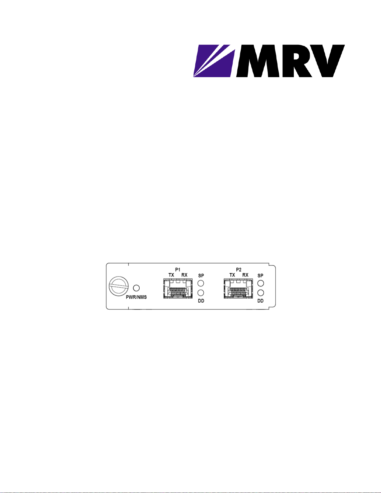
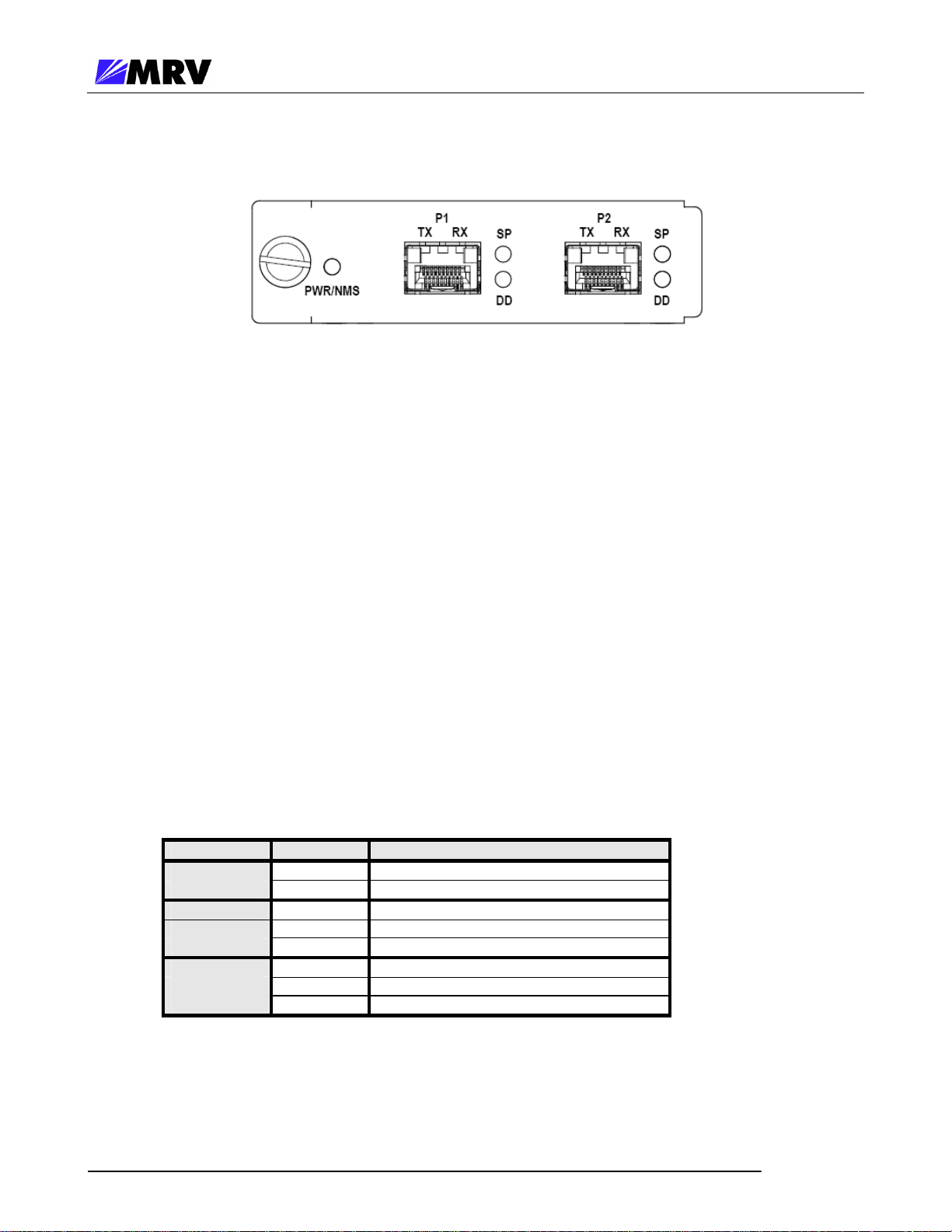
3.2 Front Panel Description
Figure 2 -- Front Panel Schematic of the EM316-2SFP
The EM316-2SFP module is equipped with the following interfaces:
Port 1 (P1): SFP port rated 100 Mbps to 2.7 Gigabit depending on SFP interface
Port 2 (P2): SFP port rated 100 Mbps to 2.7 Gigabit depending on SFP interface
Cable Lengths
The maximum cable length for SFP links is dependent upon the optical characteristic of the SFP
transceivers only. The EM316-2SFP module does not affect cable length. In the case of a copper
SFP, the maximum cable length is 100 meters.
3.2.1 LED Display Information PWR/NMS: Indicates power and management support
SP (each port): Indicates presence of an SFP with or without
a link signal present.
DD (each port): Digital Diagnostic indicator for the SFP
inserted.
LED Color Explanation
PWR/NMS
SP
DD
Off No power to unit
Green Power OK; user wire port active
Off No SFP Present
Green Signal/Link present
Amber SFP inserted, no link/signal present
Off Digital Diagnostics not supported
Green No alarm
Amber Alarm
Figure 3 -- LED Legend
P/N 1259003-001 Rev C3 4

EM316-2SFP User Guide
3.3 DIP Switch Configuration
The EM316-2SFP factory default configuration is designed to operate in the most common
applications.
Network Management = Enabled
LIN = Disabled
Loopback = Disabled
The default configuration optimizes the EM316-2SFP module in most applications. Network
management configuration does not override hardware DIP switch settings. These settings can
only be changed using the DIP switches (SW1) on the EM316-2SFP module, regardless of
previous card installations and network management configuration.
Refer to network management sections of this document, the Command Line Interface User Guide,
or MegaVision documentation for additional information about EM316-2SFP management.
DIP Switch Settings
SW # Function ON OFF Default
1 Loopback Disable Enable ON
2 NMS Disable Enable OFF
3 LIN Disable Enable ON
4 RESERVED
Figure 4 – DIP switch settings
EM316-2SFP Default DIP Switch (SW1) Positions
PCB rev 003R PCB rev 004R PCB rev 006R
Figure 5 -- DIP switches and PCB revision examples
The DIP switch components and labeling has changed between PCB revisions. Figure 5 above
illustrates some DIP switch examples by PCB revision. Note that the ON position in these
revisions, as labeled on the DIP switch component, represents DISABLE for the feature as
described in Figure 4. Refer to the pictures above for proper DIP switch polarity on the PCB
revisions cited.
Must remain ON
P/N 1259003-001 Rev C3 5

EM316-2SFP User Guide
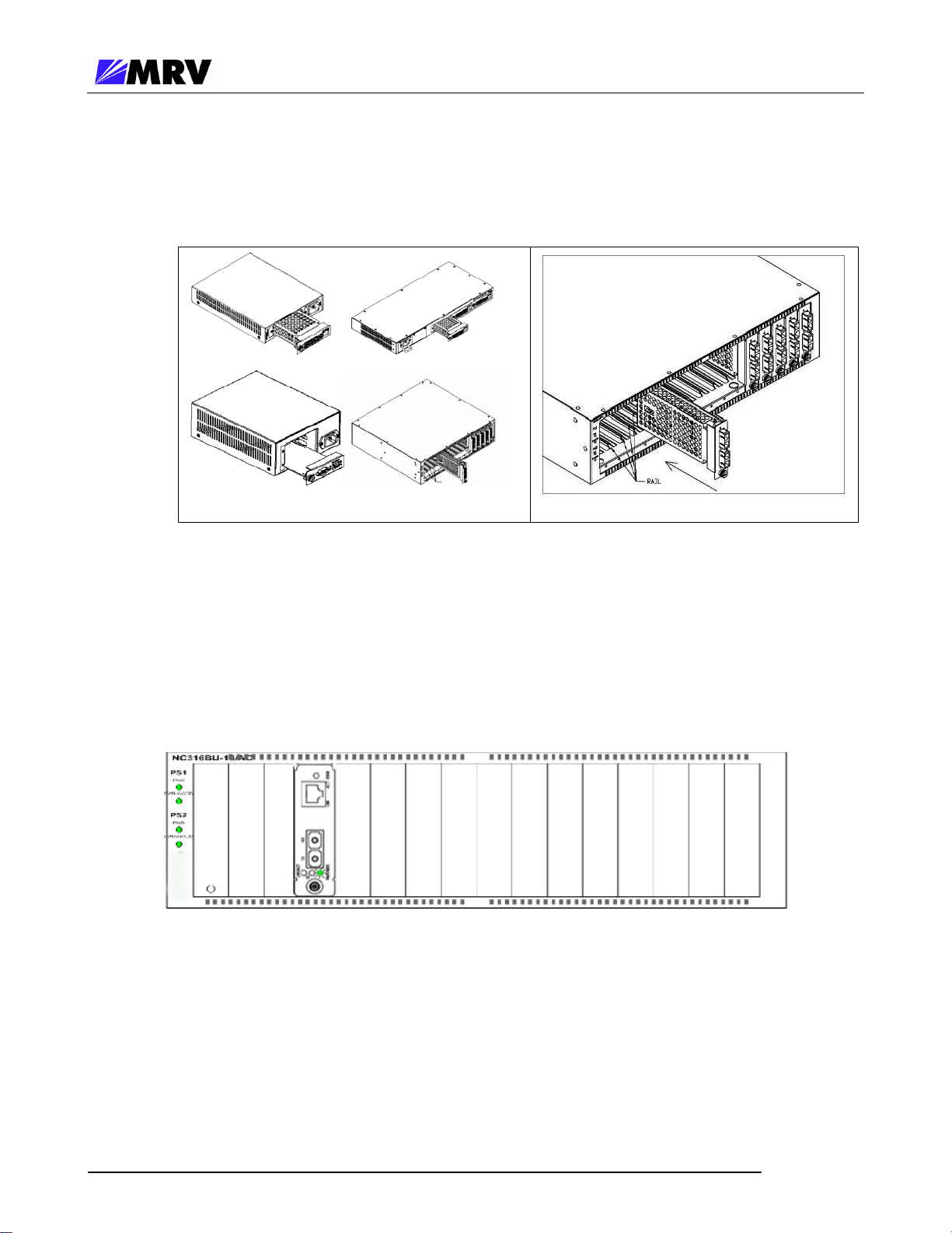
3.4 Module Installation
EM316xx cards are hot-swappable, and they are designed to insert into a powered Fiber Driver
chassis. Install the EM316xx module into a single slot or multiple slot chassis by aligning the edge
of the card with the rail of the chassis and hand-tighten the thumb screw.
The thumb screw points to the left in the BU-1, BU-2, BU-3, and BU-4 chassis. The thumb screw
points to the bottom in the BU-16 chassis.
Tools
• 6-inch Phillips screwdriver (for some module screws)
• 6-inch flat-tip screwdriver
Procedure
Follow all guidelines to eliminate static electricity while handling the module and other electronic
devices. Refer to the front of this manual for some suggestions.
Step 1. If a blank panel is covering the target slot, remove it by unfastening the two screws with
a 6-inch Phillips screwdriver.
Figure 6 -- Remove the required blank panels
To comply with FCC regulations and to optimize air flow, a cover panel or a module must cover
every chassis slot. No chassis slot should remain open when the unit is operational to limit
external signal radiation. Securing modules and panels with appropriate screws is also
important for grounding and compliance.
P/N 1259003-001 Rev C3 6
EM316-2SFP User Guide
Step 2. Install the module inside a Fiber Driver chassis by aligning the edge of the card with the
rail of the chassis. Tighten the thumbscrew by hand.
Figure 7 -- Module installation (not all chassis are shown)
Handle the module by the edges to avoid damaging any components. Follow all ESD
precautions listed at the front of this manual. Use your thumb to push the module securely into
the chassis slot. Do not use excessive force, but make sure the module connector is fully
inserted in the chassis. Secure the module by hand using the thumbscrew.
Figure 8 -- Correctly inserted Fiber Driver module in a powered chassis
P/N 1259003-001 Rev C3 7
EM316-2SFP User Guide
3.5 Small Form Pluggables (SFP): Handling and Installation
The EM316-2SFP accepts any SFP that complies with the MSA standard. Use MRV components
for guaranteed results.
Follow all ESD precautions listed at the front of this manual.
3.5.1 Cleaning Fibers
Fiber optic components and cables are very sensitive to dirt, dust and mishandling, especially in highspeed networks. Dirty or mistreated fiber may cause errors and an unwanted degradation of signal
quality.
Prior to an installation the fiber and fiber optic transceivers should be cleaned following the
procedure below.
3.5.1.1 Cleaning Supplies
• Optical cleaner cartridge
• Can of compressed air
3.5.1.2 Cleaning Procedure:
1. Blow a stream of compressed air on the fiber ends while the caps are in place.
2. Remove the caps, and blow the ends of the fibers again.
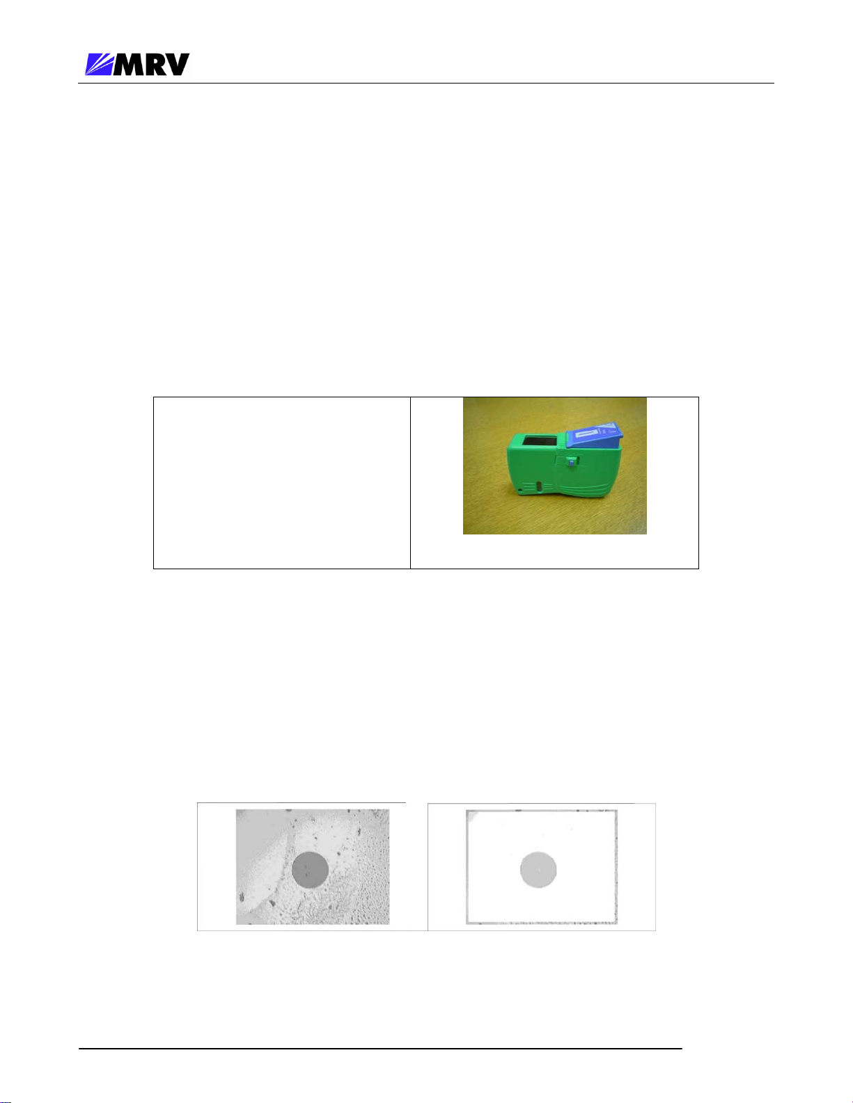
3. Clean the ends of the fibers using the cleaner cartridge; follow the instructions
Fiber Inspection
Figure 9 -- Cleaning cartridge
included with the cartridge.
Figure 10 -- Contaminated fiber and clean fiber through a scope
P/N 1259003-001 Rev C3 8
 Loading...