

Page 1
Operation manual OPTIMA7
6902EN
MRU GmbH, D-74172 Neckarsulm 1 / 51
Page 2

Operation manual OPTIMA7
Manufacturer:
Legal notices / Intellectual property rights comments
Original user manual
© 2018 by MRU
No part of this manual my be published in any form (print, fotocopy, electronic media or
any other publication form) without a written approval by the publisher.
All user trade marks and name mark descriptions, even those which are not marked as
such, are properties of the respective owners.
Edition: 20190227-V2.0
2 / 51 MRU GmbH, D-74172 Neckarsulm
Page 3

Operation manual OPTIMA7
Content
1 Introduction ................................................................................................................. 5
1.1. Intended use ......................................................................................................... 5
1.2. The company MRU GmbH ................................................................................ 6
1.3. Analyzer details .................................................................................................... 7
1.4. Packaging ............................................................................................................... 7
1.5. Return of hazardous materiales ...................................................................... 7
1.6. Return of electronic equipment ..................................................................... 7
2 Safety ............................................................................................................................ 8
2.1. Safety details ......................................................................................................... 8
2.2. Ensure safety ......................................................................................................... 9
Lithium-Ion battery user guidelines
3 Description ................................................................................................................. 10
3.1. The Analyzer ....................................................................................................... 11
3.2. The condensate separator (water trap) ..................................................... 12
3.3. Extraction probes.............................................................................................. 13
3.4. The display .......................................................................................................... 14
3.5. The keypad.......................................................................................................... 14
3.6. Menu configuration ......................................................................................... 15
....................................................... 9
4 First usage .................................................................................................................. 16
4.1. Preparing steps .................................................................................................. 16
4.2. Settings ................................................................................................................ 16
4.3. Switch-ON protection ..................................................................................... 17
4.4. Setting printer type and print out ............................................................... 18
4.5. Bluetooth settings ............................................................................................ 18
4.6. Set time and date.............................................................................................. 19
4.7. Measurement program configuration ....................................................... 19
4.8. Set CO limits ....................................................................................................... 19
4.9. Select fuel types and O2 reference .............................................................. 20
4.10. User definable fuel types (only If combustion calculation is ON) ..... 21
4.11. Define the measuring window ..................................................................... 22
4.12. Define of the zoom function ......................................................................... 22
4.13. Change measurement program names .................................................... 22
4.14. Core flow search ................................................................................................ 22
5 Maintenance .............................................................................................................. 23
5.1. Cleaning ............................................................................................................... 23
5.2. Annual service and calibration ..................................................................... 23
6 Preparation for each measurement ......................................................................... 24
6.1. Power supply ...................................................................................................... 24
6.2. Auto OFF .............................................................................................................. 24
6.3. Measurement with battery charger/battery charging ......................... 24
6.4. Measurement with battery (Battery monitoring) .................................. 24
6.5. Operation temperature .................................................................................. 24
MRU GmbH, D-74172 Neckarsulm 3 / 51
Page 4

Operation manual OPTIMA7
7 Operation ................................................................................................................... 25
7.1. Power ON and zeroing .................................................................................... 25
7.2. Selection of the measurement program................................................... 25
7.3. Combustion test ................................................................................................ 26
7.4. Core flow search ................................................................................................ 26
7.5. Measured value display .................................................................................. 27
7.6. Non-continuous draft measurement ......................................................... 27
7.7. CO-limit (without purging) ............................................................................ 28
7.8. CO-purging (optional) ..................................................................................... 28
7.9. CO/H2 and CO high (optional) ..................................................................... 28
7.10. Test program ...................................................................................................... 29
7.11. CO-ambient ........................................................................................................ 29
7.12. Temporary buffer .............................................................................................. 30
7.13. Storage the measuring results ..................................................................... 30
7.14. Printing the measuring results ..................................................................... 31
7.15. Last measurement results .............................................................................. 31
7.16. Pressure measurement ................................................................................... 32
7.17. Differential temperature measurement (optional) ............................... 32
7.18. Last measured values ...................................................................................... 32
8 Data Storage .............................................................................................................. 33
8.1. Data storage organisation ............................................................................. 33
8.2. Data storage information ............................................................................... 33
8.3. Sites administration ......................................................................................... 33
8.4. New entry and change of sites ..................................................................... 35
8.5. Delete sites .......................................................................................................... 35
8.6. Data transfer using the SD card ................................................................... 36
8.7. Measurement in Data storage ...................................................................... 38
9 Extras / Adjustment ................................................................................................... 40
9.1. Service calibration menu ............................................................................... 40
9.2. Factory settings ................................................................................................. 40
9.3. Service values ..................................................................................................... 40
9.4. Analyzer and accessories leak test .............................................................. 41
9.5. Contents SD card .............................................................................................. 42
9.6. Contents Analyzer information, ................................................................... 43
10 Appendix ................................................................................................................ 44
10.1. Text input ............................................................................................................ 44
10.2. Asking user for a decision .............................................................................. 44
10.3. Firmware update............................................................................................... 45
10.4. Using the USB Port ........................................................................................... 45
10.5. Technical data .................................................................................................... 46
Analisis and calculations ............................................................................................. 48
10.6. Fuel type list ....................................................................................................... 48
10.7. Troubleshooting ............................................................................................... 49
10.8. Declaration of conformity OPTIMA7 ........................................................ 51
4 / 51 MRU GmbH, D-74172 Neckarsulm
Page 5

1 Introduction
• This manual enables you to understand and safely operate this OPTIMA7
combustion analyzer.
Please read this manual with great vigilant and get familiar with the product
before using it.
• This analyzer may only be operated by competent personnel and for its in-
tended use.
• Please pay special attention to all safety directions and warnings to prevent
personal injuries and damaging of the product.
• We can’t be held responsible for any injuries and/or damages that occur by
not following the instructions in this manual.
• Always keep the manual near you when working with the analyzer, to be
able to read instructions as needed.
Please ensure to hand over all documents to when handing the analyzer
over to others.
Operation manual OPTIMA7
1.1. Intended use
The OPTIMA7 analyzer is intended for short-term measurement in the context of emission
control measurements and adjustments at small furnaces. The analyzer measures the
measurements provided by VDI4206 and EN50379 metrics and stores them for further processing.
The OPTIMA7 analyzer is specifically not intended as a safety device or personal protective
equipment; it should not be used as a warning device to warn people against the presence
of harmful gases.
The OPTIMA7 analyzer may only be used as indicated in this manual. Our analyzers are
checked according to the following regulations: VDE 0411 (EN61010) and DIN VDE 0701
before they leave the MRU GmbH factory.
MRU technical products are designed and manufactured according to DIN 31000/ VDE
1000 and UVV = VBG 4 of the professional guilds for fine mechanics and electrical engineering.
MRU GmbH assures that the analyzer complies to the essential requirements of the legal
regulations of the member states of the electro-magnetic compatibility (89/336/EWG).
MRU GmbH, D-74172 Neckarsulm 5 / 51
Page 6
Operation manual OPTIMA7
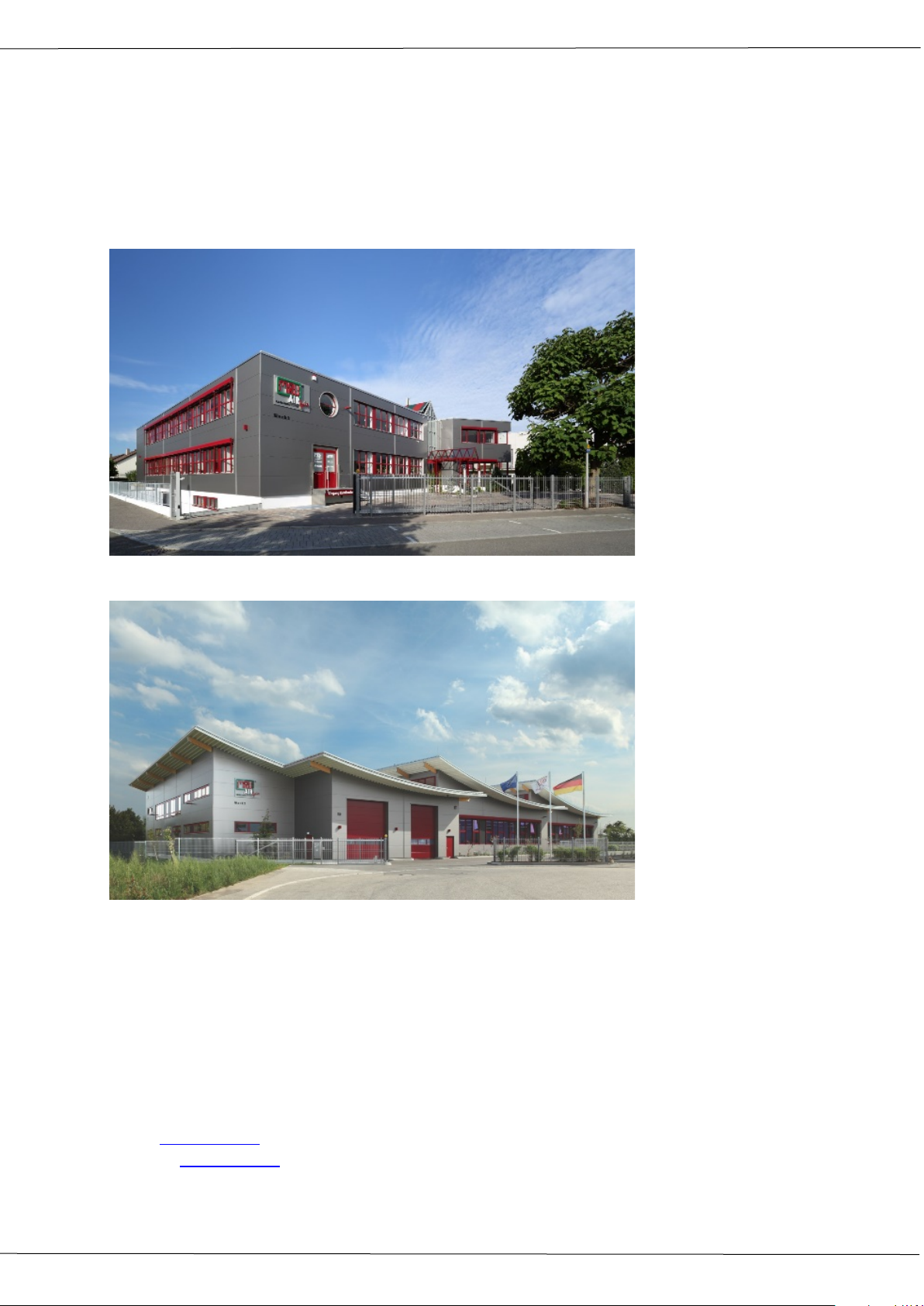
Plant 1: Sales, Service, R&D
Plant 2: Production
1.2. The company MRU GmbH
The OPTIMA7 analyzer is manufactured by the MRU GmbH in Neckarsulm Germany
(founded in 1984), a medium sized company that specializes in developing, producing and
marketing high quality emission monitoring analyzers. MRU GmbH produces a wide range
of instruments, from standard analyzers up to tailor made industrial analyzers. MRU GmbH
contact details are listed on the previous page.
MRU GmbH
Fuchshalde 8 + 12
74172 Neckarsulm - Obereisesheim
GERMANY
Phone +49 71 32 99 62 0 (Front office)
Phone +49 71 32 99 62 61 (Service)
Fax +49 71 32 99 62 20
Email: [email protected]
Internet: www.mru.eu
6 / 51 MRU GmbH, D-74172 Neckarsulm
Page 7

1.3. Analyzer details
• The analyzer is not suitable for long term (continuous) measurements (this is
a spot analyzer).
• Before using the analyzer verify the condition of the various parts of the ana-
lyzer, such as the probe, the ambient air conditions, the condensate separator, star filter and the connectors for damage and/or blockages.
• When starting the analyzer up it will take between 1 – 3 minutes to set to
zero depending on the condition of the sensors and ambient conditions.
(Zeroing).
• The minimum zeroing time of the analyzer to achieve correct measurement
values can be expected by 1.5 minutes!
• Caution: Exposure to acids; aggressive gases such as Sulphur; vapors such
as thinners, gasoline, alcohol and paint, etc. can damage, reduce the life of,
or destroy the sensors.
• The life of the sensors depends on how they are used, maintained and
treated. Typical average life expectations are: O2 - 2 years; CO - 2 - 3 years
and NO - 3 years.
• The battery life is at least 500 charge-discharge cycles. With increasing num-
ber of charging cycles the battery capacity (indicated in operating hours) is
reduced.
Operation manual OPTIMA7
1.4. Packaging
Please keep and store the packaging material to be able to use it when your analyzer must
be sent back for service and calibration.
1.5. Return of hazardous materiales
Waste Disposal/Returns/Warranty - MRU GmbH is required to accept the return of hazardous waste such as electro-chemical sensors that cannot be disposed of locally.
Hazardous waste must be returned to MRU prepaid.
1.6. Return of electronic equipment
MRU GmbH is required to accept the return, for proper disposal, of all analyzers delivered
after 13th of August 2005.
Analyzers must be returned to MRU prepaid.
MRU GmbH, D-74172 Neckarsulm 7 / 51
Page 8
Operation manual OPTIMA7
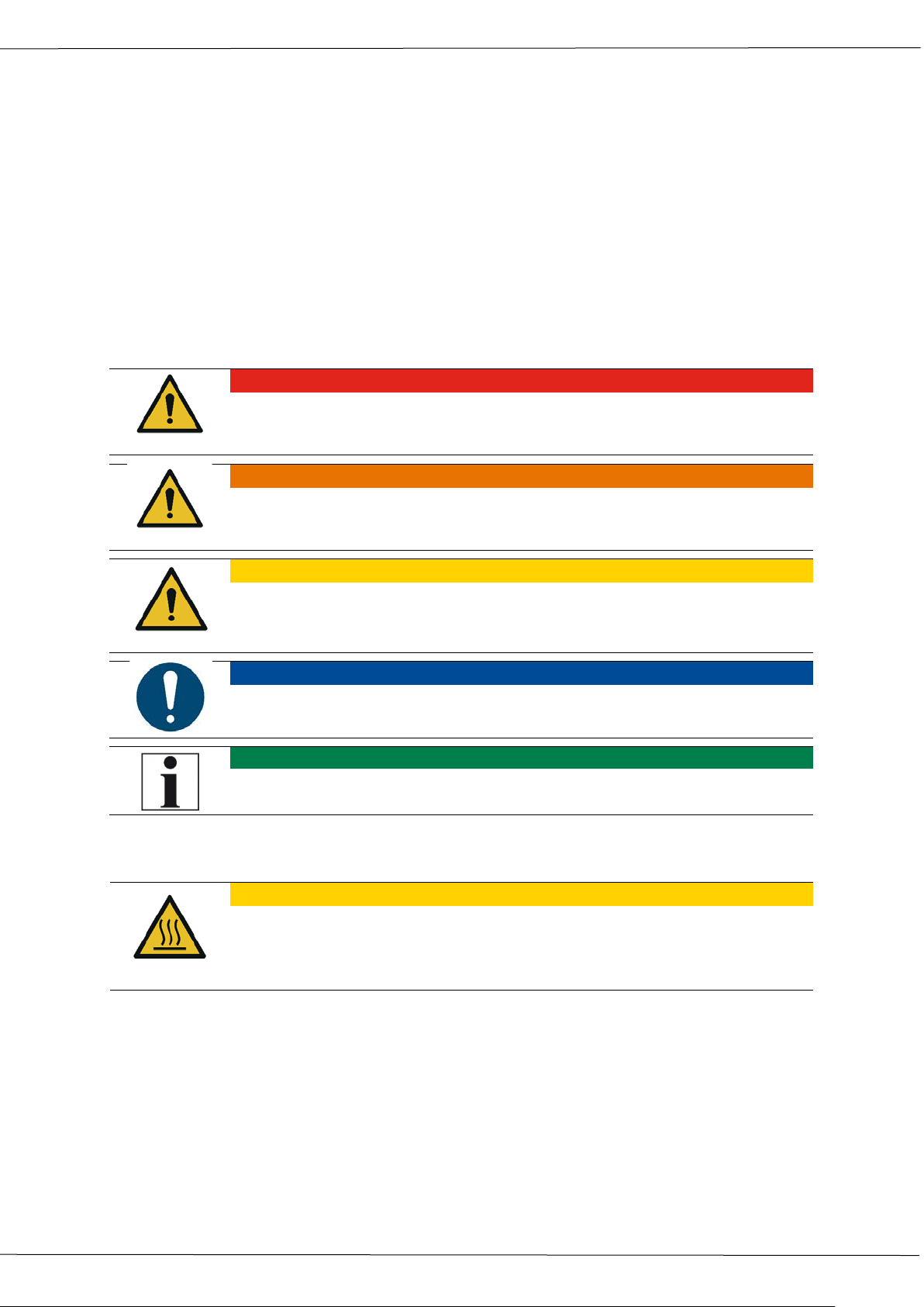
• DANGER
Describes an immediate threat of danger which can cause mayhem or
• WARNING
Describes an immediate threat of danger which can cause mayhem,
• CAUTION
Describes a possible danger that can cause risk of injury.
ATTENTION
Describes a possible harmful situation which can damage the analyzer or
NOTE
Gives user hints and other important information.
• CAUTION
HOT – danger of burns and fire hazards from gas extraction probe.
2 Safety
Safety and warning notices point out possible dangers to the reader of this manual.
In this manual safety and warning notices are typically above actions that might cause
harm or danger.
2.1. Safety details
The explanation of safety notices:
Not following the safety and warning notices may cause physical harm and/or property
damages, as well as the loss of warranty of your analyzer.
The following safety and warning notices must be obeyed at any time!
can even cause death.
property damage or can even cause death.
its surroundings.
The explanation of safety notices:
Physical harm and property damage can be caused.
► Cool down the probe tube.
8 / 51 MRU GmbH, D-74172 Neckarsulm
Page 9
NOTE
The battery is inside the analyzer and is not accessible to the
2.2. Ensure safety
• The analyzer may only be used for its intended purpose and within its de-
fined technical parameters. Don’t use any force and avoid dropping the analyzer.
• Don’t use the analyzer when there are visible damages of the enclosure, the
charger or supply lines.
• Don’t store the analyzer together with solvents and don’t use any drying
agents.
• Only perform maintenance procedures that are described in this manual and
always obey the instructions.
• Only operate the analyzer in closed and dry rooms, protect the analyzer
against rain and moisture.
• Only operate the analyzer with the supplied battery charger.
• Never us the probe tube and other metal parts / accessories as electric con-
ductors.
• The analyzer may not be positioned near open fire or extreme heat.
• The defined temperature range of the extraction probe / probe tube may
not be exceeded, the probe tube and/or thermo-element can be destroyed.
Operation manual OPTIMA7
Lithium-Ion battery user guidelines
end-user.
Below are some guidelines you need to know about Lithium Ion batteries and the handling of these
• The rechargeable battery may only be used for this OPTIMA7analyzer.
• Don’t charge the analyzer in extreme heat, don’t store the battery in a hot
environment and don’t throw the battery into fire.
• Don’t try to modify the battery, shortcut it or put any mechanical force to it!
• The battery may not be used in or under water.
• Avoid mechanical force and don’t throw that battery.
• Don’t cut or squeeze the battery cables!
• Don’t carry or store the battery together with sharp objects.
• Don’t connect the (+) contact with the (-) contact or connect these to a
metal object.
• Not obeying the above instructions can cause heat, fire and explosion.
.
MRU GmbH, D-74172 Neckarsulm 9 / 51
Page 10
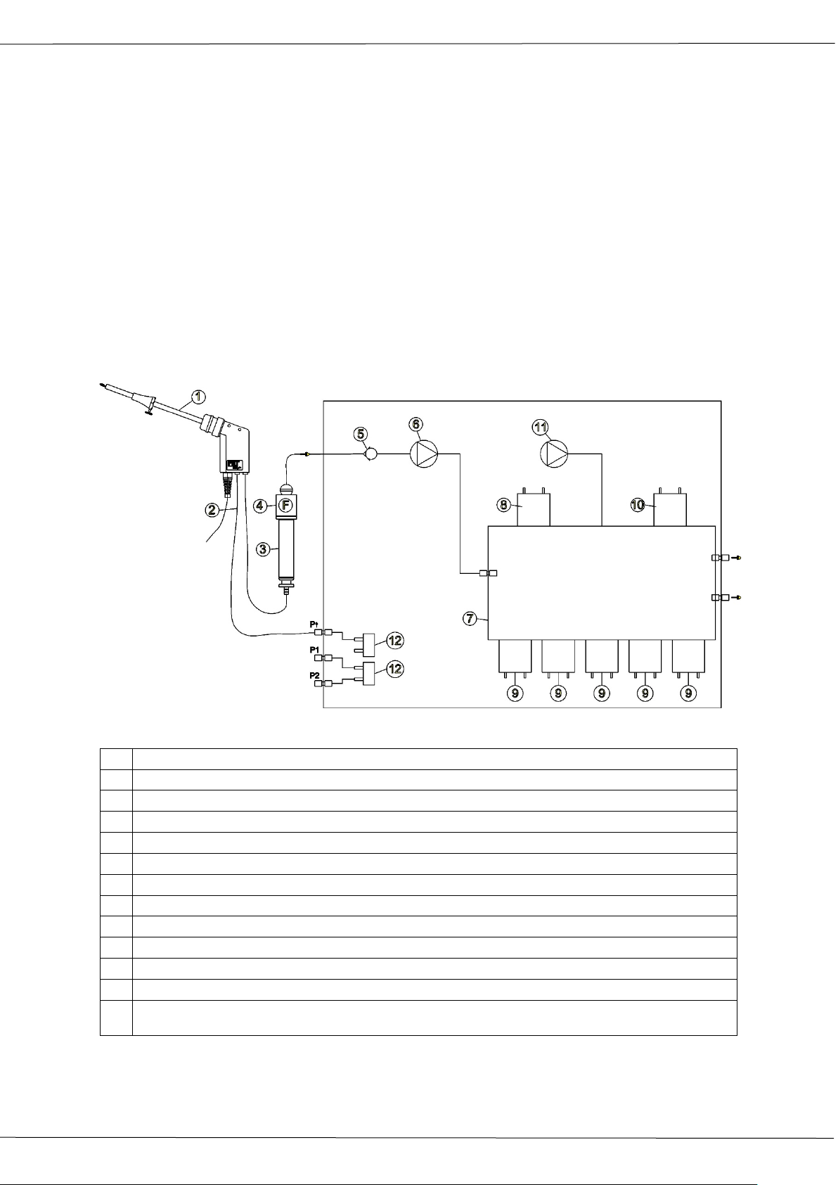
Operation manual OPTIMA7
1
Sampling probe
2
Triple hose
3
Condensate separator
4
Star filter
5
Non return valve
6
Gas pump
7
Sensor chamber
8
O2-Sensor
9
Further electrochemical sensors optional*
10
CO2 NDIR *
11
CO Purge pump * / not available with CO2-NDIR
12
Pressure sensor *
*optional
3 Description
The main task of the OPTIMA7 analyzer is to assist with precision control and adjustment
measurements of gas, oil and wood fired furnaces.
Available options for this and other analyzers can be found on the MRU Homepage or
speak to a member of our sales team.
Gas schematics diagram
In combination with the extraction probe (inserted in the stack) the internal gas pump of
the OPTIMA7 analyzer extracts a portion of the flue gas and analyzes it using electro-chemical sensors.
The thermo-element in the probe tube measures the flue gas temperature and due to the
construction of the probe pressure (draft) can be measured as well.
10 / 51 MRU GmbH, D-74172 Neckarsulm
Page 11
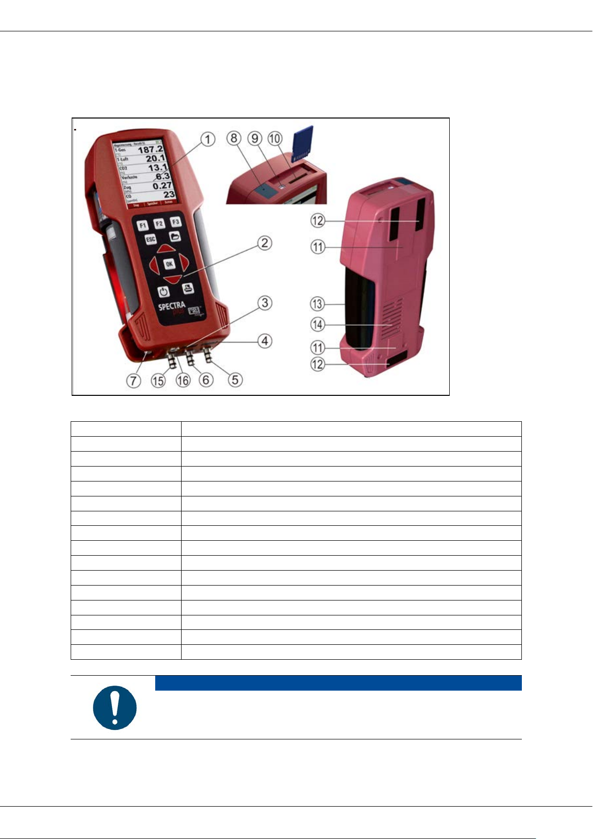
Operation manual OPTIMA7
1
Display
2
Key pad
3
Temperature connector T2
4
Temperature connector T1
5
Pressure connector P1
6
Pressure connector P2
7
Gas outlet
8
IR-Interface
9
USB-port and charging port
10
SD-card reader
11
Fixing magnets
12
Analyzer feet
13
Handle strip
14
Gas outlet
15
Pressure connector P3
16
Connector AUX
IMORTANT
Gas outlet:
3.1. The Analyzer
The compact analyzer is made from a fiber re-enforced plastic material with all measurement related connections at the bottom of the analyzer.
,
MRU GmbH, D-74172 Neckarsulm 11 / 51
During measurement the gas outlet must not be covered
Page 12
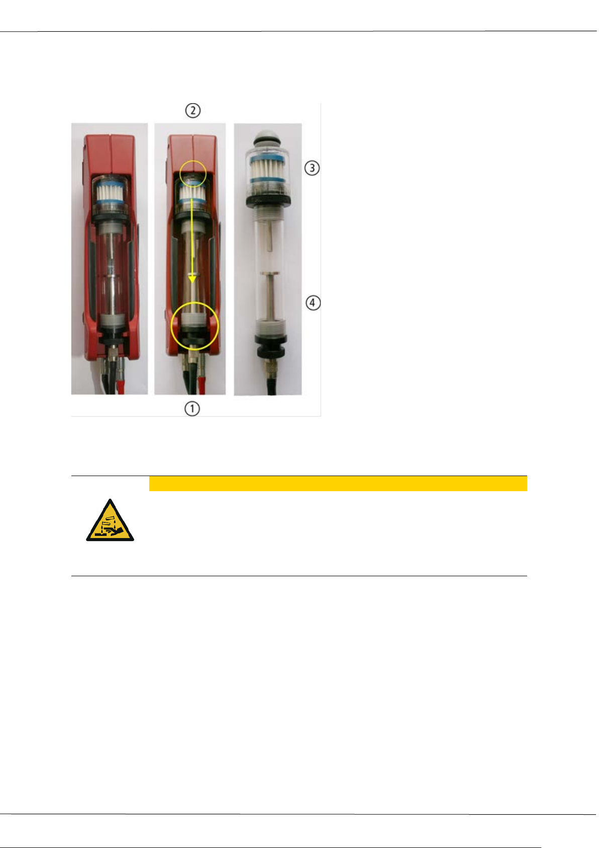
Operation manual OPTIMA7
•
Condensate is acidic
3.2. The condensate separator (water trap)
During the measurement accumulating condensate is collected in the condensate separator
Remove the condensate separator by pulling it towards you (1) out of the groove of the
OPTIMA 7 housing, then pull it downwards (2).
CAUTION
The condensate from the container can be slight acidic and can cause
chemical burn.
► Immediately clean with plenty of water once you have encountered
acid
Condensate vessel and plugs are screwed together. To change the filter and dry and clean
the condensate separator this can be easily disassembled and screwed together again.
After cleaning, a leak test must be proceed
In the condensate separator of the OPTIMA7 an exhaust gas filter is attached. This filter out
the first coarse dirt. This pocket star filter is washable and can be used 4-5 times afterwards.
Frequent measurements result in a high degree of contamination which requires regular
replacement of this filter.
12 / 51 MRU GmbH, D-74172 Neckarsulm
Page 13
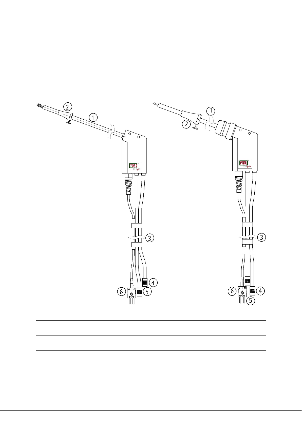
Operation manual OPTIMA7
Probe ST
Probe SF
With 180 mm probe pipe (fixed)
With 300 mm exchangeable probe pipe
1
Probe tube
2
Probe cone ( high grade steel)
3
Triple hose (NBR or Viton)
4
Connector for sample gas measurement
5
Connector for draft measurement
6
Connector for temperature measurement
3.3. Extraction probes
The OPTIMA7 is available with either a probe with fixed probe tube or with exchangeable probe
tubes. A complete list of available probe options can be found in our effective price list.
Here are 2 possible options:
and 1,5 m sampling line
and 2,7 m sampling line
MRU GmbH, D-74172 Neckarsulm 13 / 51
Page 14
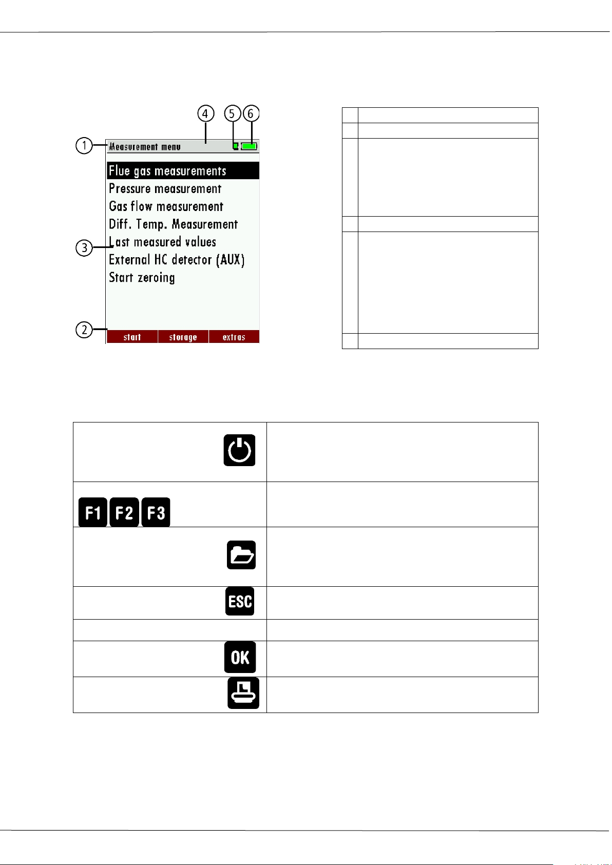
Operation manual OPTIMA7
Press to start the analyzer without delay. The
lyzer will recommend the purging of the sensors.
Function Keys
Activates the functions seen on the display (2
Will show all available functions in the window
the three function keys.
ESC Key
Abort or return to the menu above
Jump in between lines, change values
OK Key
Confirmation key, select a marked menu point
Printer Key
Activates the printer function in the measurement
1
Menu bar
2
Function key bar
3
Display panel
4
Zeroing active
5
SD-Card in the slot
6
Battery charge condition
3.4. The display
All information required to operate the analyzer is displayed as shown below.
1. Menu
2. Measurement value
3. …
4. Indication green
Read- and write access
5. Indication yellow
only Read access
(SD-Card write protected)
3.5. The keypad
Description and function of the keys:
ON/OFF
Menu Key
Arrow Keys
power off function will be delayed to protect the
sensors. If there is not enough ambient air the ana-
function key bar)
that is currently in use – also those which have an
individual key on the key pad like the printer and
14 / 51 MRU GmbH, D-74172 Neckarsulm
and service window.
Page 15
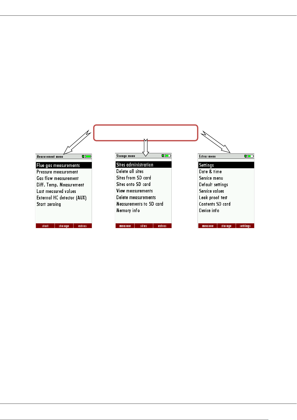
Operation manual OPTIMA7
The topic „Flue gas meas-
flyer.
Please read chapter 8 for
Please read chapter 9 for
OPTIMA 7
3.6. Menu configuration
The OPTIMA 7 organizes all available actions in three main menus:
Menu Measurement all tasks for the measurement pro-
grams of the analyzer. Here you can select all installed and
available measurement programs.
Menu Memory all tasks for the management of the data
memory available.
Menu Extras all the other available tasks – for management
and customizing your analyzer.
urements „is a standard feature in every analyzer and is
explained in chapter 7
Other menu points are optional and will be explained
either in this manual or in
an additional manual or
You can jump in between the 3 main menus with the 3 function keys (according to the displayed name on the screen).
details.
details.
MRU GmbH, D-74172 Neckarsulm 15 / 51
Page 16
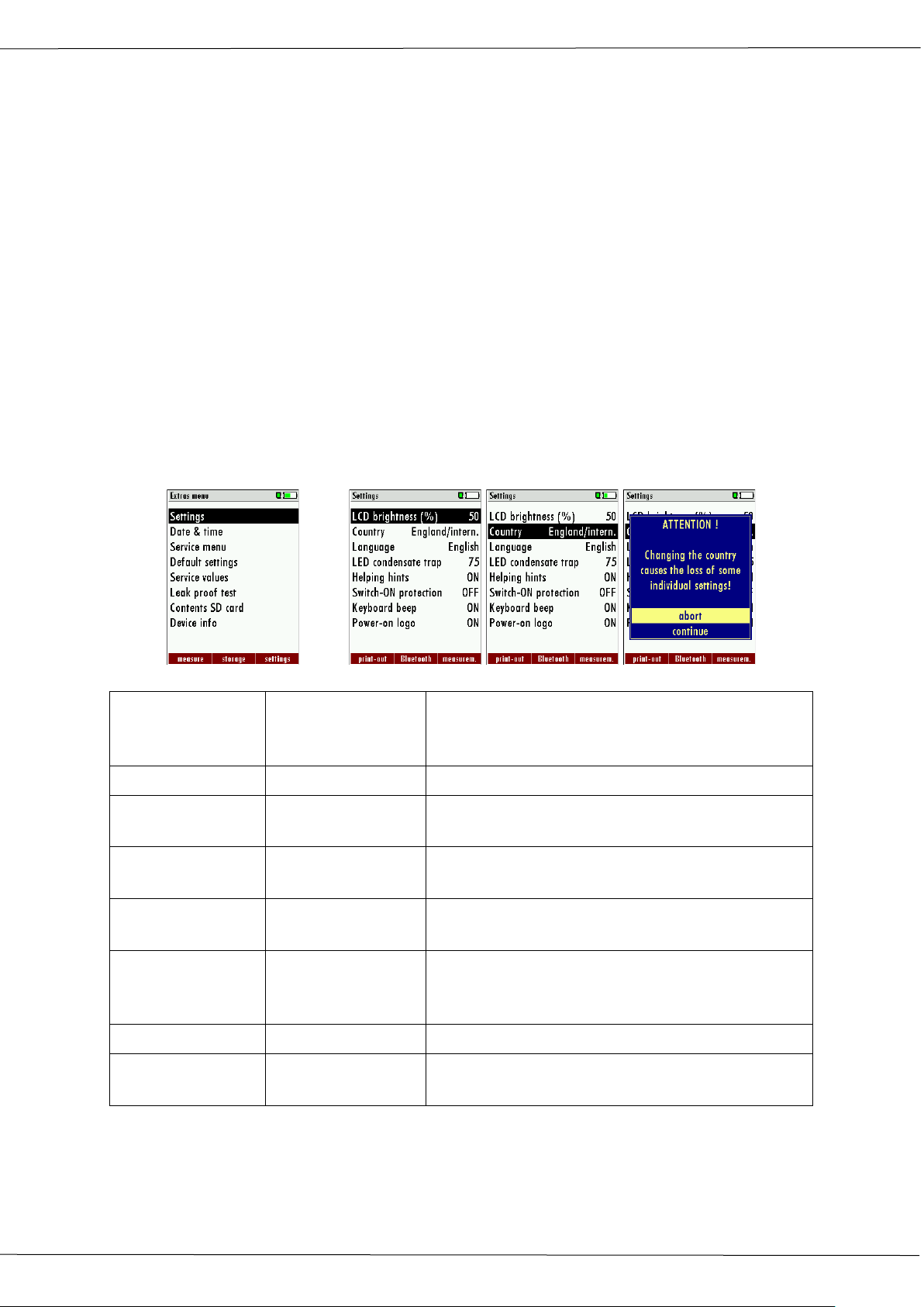
Operation manual OPTIMA7
LCD brightness
4 First usage
Once you have determined that the analyzer is safe to be used, it can now be customized
to meet your needs, these modifications can be changed at any time.
4.1. Preparing steps
• Remove the analyzer from its packaging and read the complete manual.
• The analyzer has left the manufacturer completely assembled and ready to
use. Check if everything indicated has been delivered and that there are no
visible damages.
• Charge the battery for at least 8 hours.
• Check and modify date and time if needed.
4.2. Settings
The “Settings” menu allows configuring some instrument specific parameters.
In the main menu “EXTRAS“ = “F3 key” - scroll down to “Settings“ then press the “OK“ key,
By selecting a line the parameter value can be changed by the arrow keys.
Language option Select device languages
Country option Enables some country specific parameters like
LED condensate
trap
Helping hints ON / OFF Helpful hints activated or deactivated (explana-
Switch-ON protection
Keyboard beeper ON / OFF Keyboard beeper activated or deactivated
Power-on logo ON / OFF Logo will be show during power-ON of the ana-
OK
5 – 100 % Display-brightness, depending on temperature
and also on the personal judgement of the user,
at 20°C a value of ca. 50% is normal
fuel types, calculated values etc.
0 … 150 Change the brightness of the condensate sepa-
rator LED
tion below)
ON / OFF If activated and if ON key is pressed (possibly in-
advertently), then the message „3 seconds OK
key press “ displays
lyzer
16 / 51 MRU GmbH, D-74172 Neckarsulm
Page 17

Operation manual OPTIMA7
Settings measurement:
Temperature Unit °C, °F Change the unit for temperature in all screens
Pressure Unit Pa, hPa/Pa, hPa,
kPa/Pa, kPa, mbar,
mmH2O, cmH2O,
inH2O, mmHg,
Change the unit for pressure in all screens. The
meaning of hPa/Pa and kPa/Pa is that the instrument performs a dynamic change of unit depending on the absolute value of pressure.
inHg, PSI,
Draft Unit Pa, hPa/Pa, hPa,
kPa/Pa, kPa, mbar,
mmH2O, cmH2O,
inH2O, mmHg,
Change the unit for pressure in all screens. The
meaning of hPa/Pa and kPa/Pa is that the instrument performs a dynamic change of unit depending on the absolute value of pressure.
inHg, PSI,
Core flow search ON / OFF Core flow search before start of each flue gas
measurement: activated or deactivated
Combustion calculation
ON / OFF If the combustion calculation is switched off fol-
lowing items will be changed:
- no fuel types, respectively always "Sample
Gas"
- no measuring values losses, Verluste, ETA,
ETAcond, Dev. point
- no measuring value CO2, except it will be
measured
- no measuring values CO/NO/,,,. in
[mg/kWh]/[mg/MJ]
- no fuel type will be shown on the menu bar
and print-out
Explanation for “Helping hints”:
Some helpful hints which are very useful for an inexperienced user but are not needed by
experienced users, can be activated or deactivated. The following hints will be affected:
“Zeroing finished, Sensors are ready. Analyzer ready for measurement.”
“Reminder! Charge batteries at regular intervals!”
“Measurement stopped/started.”
4.3. Switch-ON protection
If activated and if ON key is pressed (possibly inadvertently), then the message: „3 seconds
OK key press “displays
MRU GmbH, D-74172 Neckarsulm 17 / 51
Page 18
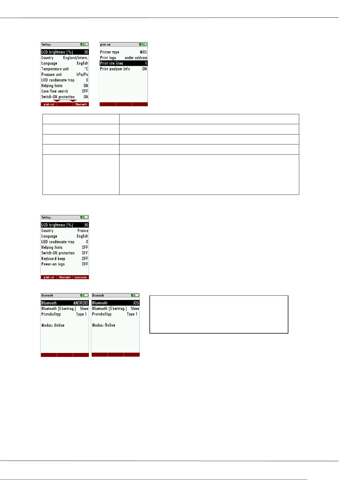
Operation manual OPTIMA7
Line 1 (Site no.) is necessary
Bluetooth -> ANDROID or iOS
4.4. Setting printer type and print out
F1
Printer type Select printer type MRU / HP
Print logo ON/OFF Print logo
Print option SHORT/LONG SHORT: Print-out without area for signature and site information
Print site lines 0 … 9
Print device info To measuring print out can be shorter designed, while the device
info will be
left out.
In some print outs (adjustment, service ...) the info will be printed
forever.
4.5. Bluetooth settings
The following MRU software can be used:
MRU4u (Bluetooth) Available in the Apple App Store and Google Play
For iOS communication with PC, tablet or smartphone is additionally
the Low power module # 66173 required
SMARTdata (Bluetooth) (SMARTdata Version 1.2.0 or newer)
MRU-Win (USB) (MRUwin Version 2.7.4.0 or newer)
ONLINEview (USB/Bluetooth) (ONLINEview Version 2.9.5 or newer)
The Bluetooth passkey is: 1234
Bluetooth (transmiss.) -> Slave
Protocol -> Type 1
Auto-connect -> OFF (if available)
Devices as of firmware version 1.66.00 with dual Bluetooth module:
The Bluetooth mode can be selected under EXTRAS / SETTINGS.
For Android devices, select the mode: ANDROID
For Apple- devices, select the mode: iOS.
Always set the BLUEGAZsmart setting to OFF!
ONLINEview must be operated in master mode - please select "Master" under Setup.
Please select "Master" under SETUP.
For further information please refer to the corresponding documentation for the respective software program
18 / 51 MRU GmbH, D-74172 Neckarsulm
Page 19
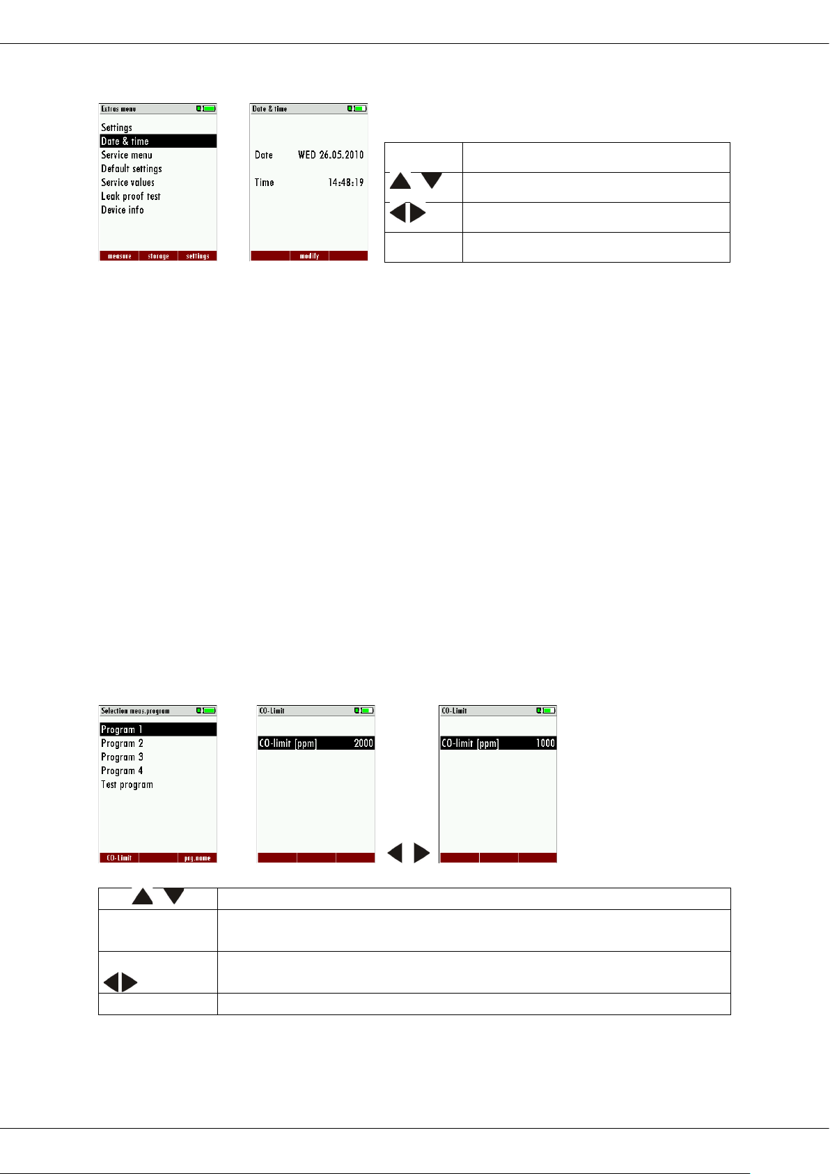
Operation manual OPTIMA7
,
Select one available program
F1
Open the CO ppm limit window
The CO-ppm limit value can be adjusted in 100 ppm steps between 300
ppm and 4.000 ppm / 10.000 ppm)
OK oder ESC
Return to the measurement window
F2
Edit
,
Change the marked number
Move the cursor to the next position
ESC
Return to Extra-Menu
4.6. Set time and date
OK
The time and date must be modified in case the battery has been discharged completely.
4.7. Measurement program configuration
(Flue gas measurements) Select one of the 6 configurable measurement programs.
For each of the programs the following parameters can be configured:
1. CO ppm limit: adjustable value for the CO sensor protection. If the CO value in
the flue gas is higher than the adjusted value in the analyzer, the purge pump will
be activated and the sensor will be protected against high CO concentrations.
(Optional)
2. Selectable fuel types: choose and select from the available fuel type list
3. Measurement windows: configuration of what and where will be displayed in the
3 measurement value windows.
4. Zoom – window: select what will be displayed in the zoom - window
5. Program name
The following program is pre-configured:
“Test Program” indented for use at instrument maintenance and calibration
4.8. Set CO limits
High CO concentrations in the gas stream can shorten the life span of your CO sensor. The
OPTIMA7 can warn the user if the analyzer exceeds a pre-defined CO limit.
F1 ,
The CO limit can be defined for each of the 4 measurement programs.
Using during the measuring the context menu and you can press the CO limit key – the CO
limit can be changed in 100 ppm steps.
MRU GmbH, D-74172 Neckarsulm 19 / 51
Page 20
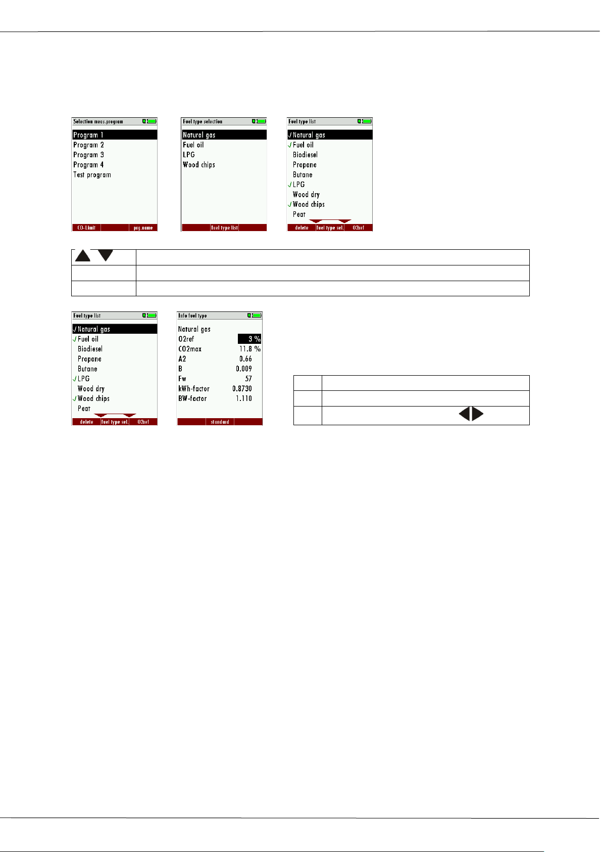
Operation manual OPTIMA7
, ,
Select a program
F1OK
Show a pre-selected fuel type
F1F2
Show the list of all fuel types
F1
Add / remove a fuel type
F2
Exit the fuel type list
F3
Input O2-ref with the keys
4.9. Select fuel types and O
reference
2
After selecting a measurement program, you can select or add fuel types. You can define
what fuel types you want to see for each measurement program by using the fuel type list.
OK F2
F3
First select a program then press OK – then press the F2 key in the window “Fuel type selection”. All available fuel types are displayed: they can be added to or removed from the
short list by using the F1 key. Added fuel types have a check mark in front of the fuel type.
To each fuel type the parameters are displayed by selecting F3 “O2Ref”. All parameters are
displayed read-only except the O” reference value that can be changed
20 / 51 MRU GmbH, D-74172 Neckarsulm
Page 21
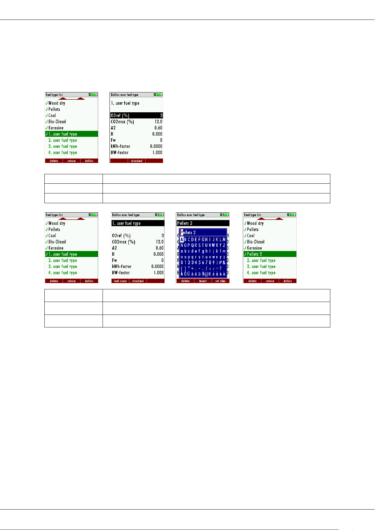
Operation manual OPTIMA7
F1
Add or remove selected fuel to the pre-selected fuel types
F2
Back to the window “Fuel type selection”
F3
Modify fuel type parameters
F3
Modify fuel type parameters
F2
Modify fuel type name Text input see chapter 10.2
OK
Save the new fuel type name
4.10. User definable fuel types (only If combustion calculation is ON)
Here, four fuels are adjusted individually. The name as well as the parameters are adjustable. As the other fuel types, they can be pre-selected or left out.
Note:
The last 4 fuel types at the list are the user fuel types. The user fuel types are coloured
green.
F3
F3 F1 OK
MRU GmbH, D-74172 Neckarsulm 21 / 51
Page 22
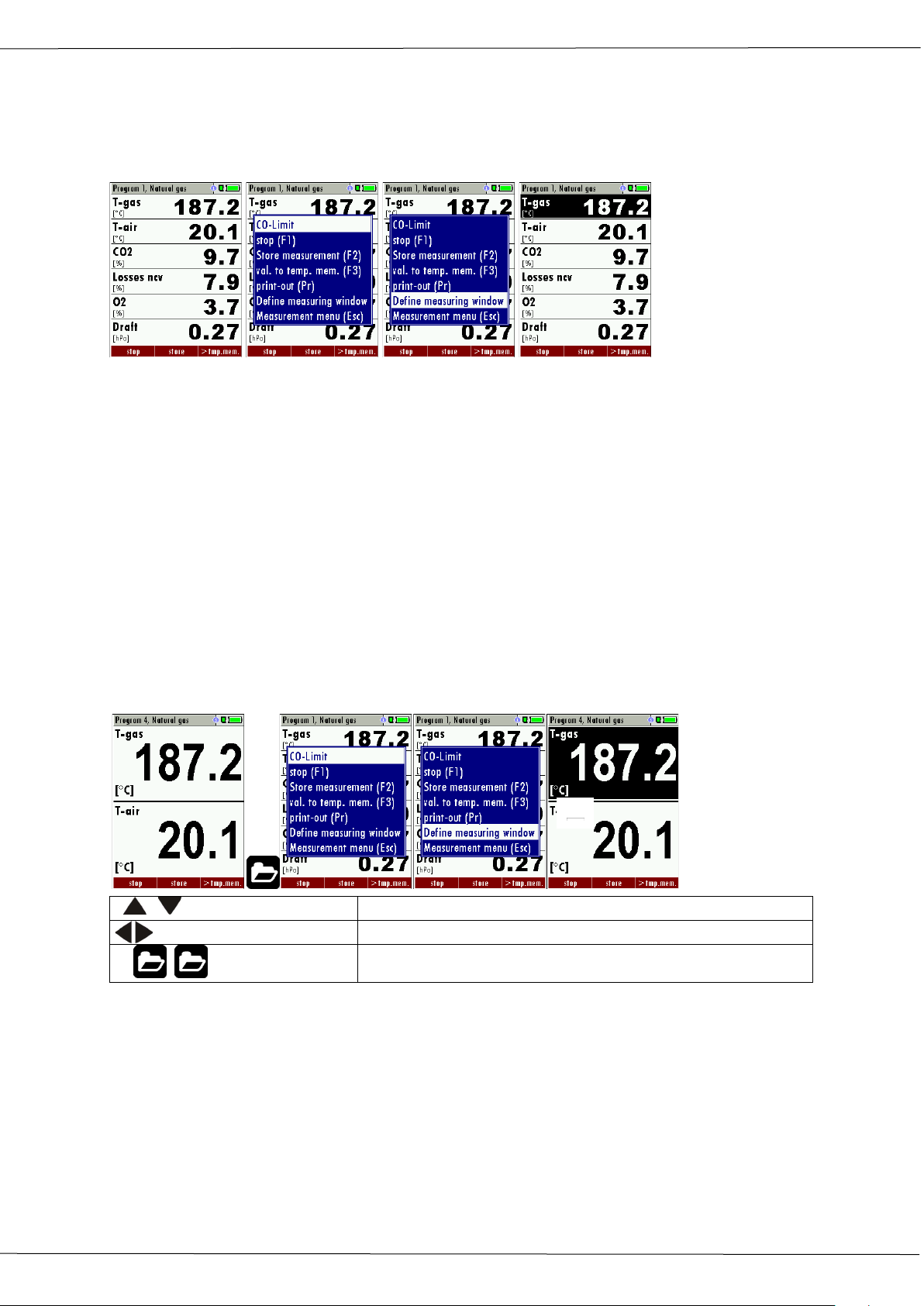
Operation manual OPTIMA7
, ,
Change Zoom window 1..3
Change measuring values
F1 ,
Save measuring window and save configuration
4.11. Define the measuring window
Start the measuring program – once you are inside the measuring window press the
menu- key.
Now you select “define measuring window” and press the OK key. The top value will now
be marked black – this black bar can be moved up and down. Move it to the position that
you would like to change or to the position where you want to add a measuring value.
Once you have reached the position you van uses the arrow left and right keys to change
the measuring value.
When all your changes have been made, you press again the menu key. Now you select
“Save measuring window”. All your changes will be saved and all saved values will be
printed when using the printer function.
Start the measuring program – once you are inside the measuring window press the menu
key.
4.12. Define of the zoom function
For each measurement program you have 3 zoom windows with two selectable values for
each window.
,
4.13. Change measurement program names
In the “Fuel type selection” window you can edit the marked program name with the F3
key and then change the program name.
4.14. Core flow search
You can choose if you want a core flow search before every measurement or not. This function is only possible in the programs 1 -4. Enabling the core flow search is a global instrument setting valid for all programs and therefore described in chapter 4.2
22 / 51 MRU GmbH, D-74172 Neckarsulm
Page 23

Operation manual OPTIMA7
• CAUTION
Condensate is acidic
5 Maintenance
The OPTIMA 7 needs to the long value preservation only one very low maintenance need:
5.1. Cleaning
Taking good care of your OPTIMA7 will ensure long-term maintenance value:
The condensate from the container can be slight acidic and can cause
chemical burn.
► Immediately clean with plenty of water once you have encountered
acid
• After each measurement: removed the hoses of the sampling from the
OPTIMA7 and let them dry (condensate inside the hoses). Open and empty
the condensate separator and let it dry.
• Occasionally: clean the sampling line.
• The pleated filter in the condensate separator can be washed 4 to 5 time
(with your work clothes in the washing machine). The grade of contamination depends on the fuel types and the number of measurements performed. Replace the filter frequently when it looks dirty.
• The internal battery has only a minor self-discharge effect. If the analyzer is
not being used over a period it is recommended to charge the battery before storing it and then recharge the battery every 8 weeks.
5.2. Annual service and calibration
An annual service and calibration is highly recommended. Please contact your local service
partner for details.
MRU GmbH, D-74172 Neckarsulm 23 / 51
Page 24
Operation manual OPTIMA7
Whenever you connect the analyzer with external battery charger
6 Preparation for each measurement
6.1. Power supply
The analyzer can be used with:
• with the internal MRU battery (provided)
• with the MRU battery charger (provided)
External equipment may only be connected while the analyzer is switched off!
6.2. Auto OFF
The instrument is automatically switched off after 60 minutes. During a measurement or a
battery charging cycle the auto off is deactivated.
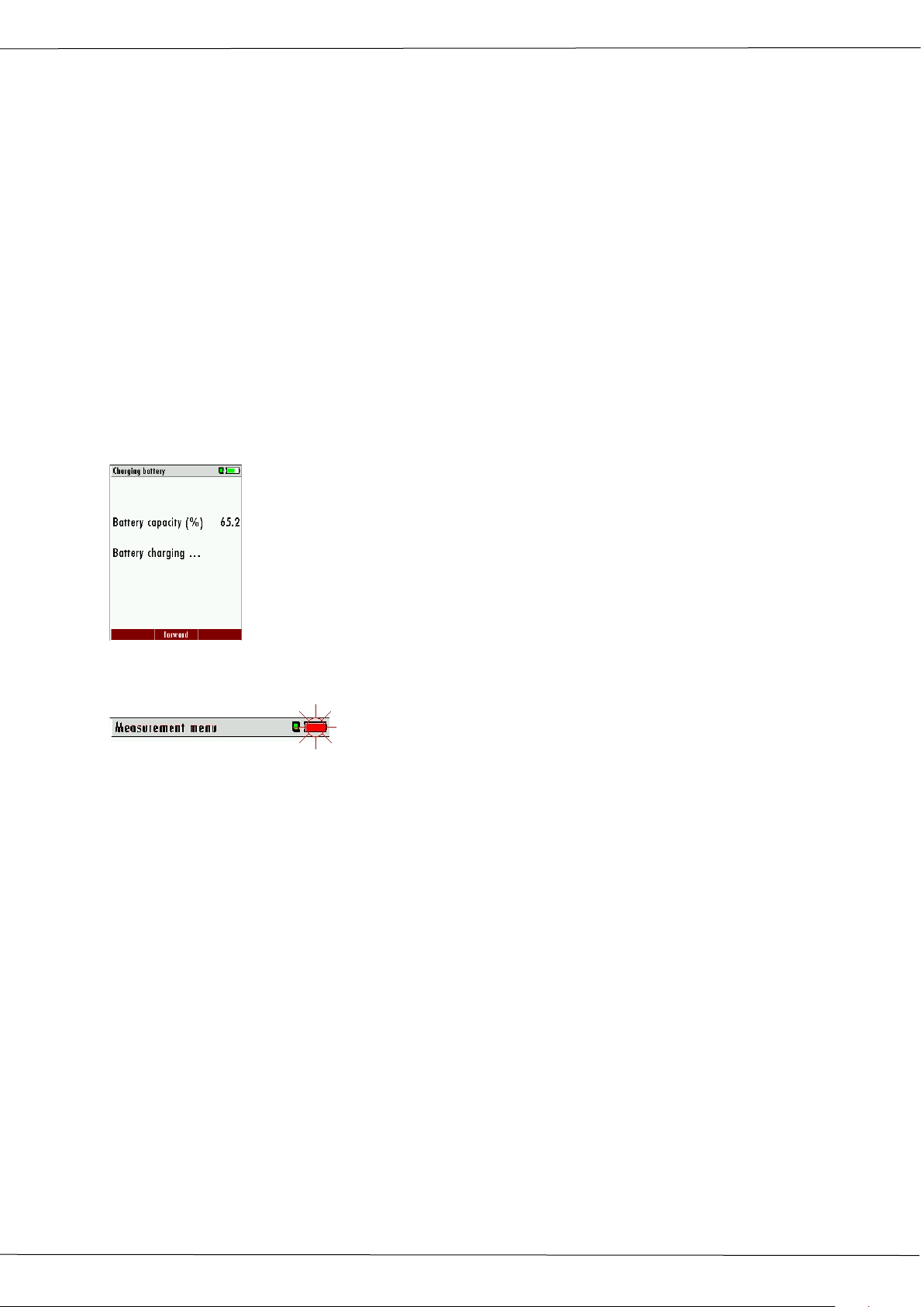
6.3. Measurement with battery charger/battery charging
(90...260 V / 50/ 60Hz) the battery will be charged
Once the battery is fully charged the analyzer will switch to trickle
charge mode.
At the moment, if the battery is fully charged and the trickle charge
mode begins, an acoustic feedback will be played.
6.4. Measurement with battery (Battery monitoring)
The battery symbol in the top right corner displays the current battery charge condition.
Approximately 15 minutes (depending on the analyzer configuration) before the battery
is drained, the battery symbol will start to blink red (about once per second).
When the battery is almost drained and the analyzer is not connected to the battery
charger within one minute, then the analyzer will switch off automatically to prevent deep
discharge of the battery.
6.5. Operation temperature
If the analyzer has been stored at low temperatures, it will require some time to equilibrate
to the ambient temperature before being switched on. If it does not equilibrate, condensation will occur inside the analyzer!
If the temperature is out of its operation range you will see the following messages on the
display: “Analyzer too hot” or “Analyzer too cold”
Once one of these messages appears you will not be able to use the analyzer, it will give an
acoustic signal until it has reached the specified operation temperature between +5°C and
+45°C
24 / 51 MRU GmbH, D-74172 Neckarsulm
Page 25
Operation manual OPTIMA7
Zeroing
OK
Start zeroing
change between the lines
7 Operation
7.1. Power ON and zeroing
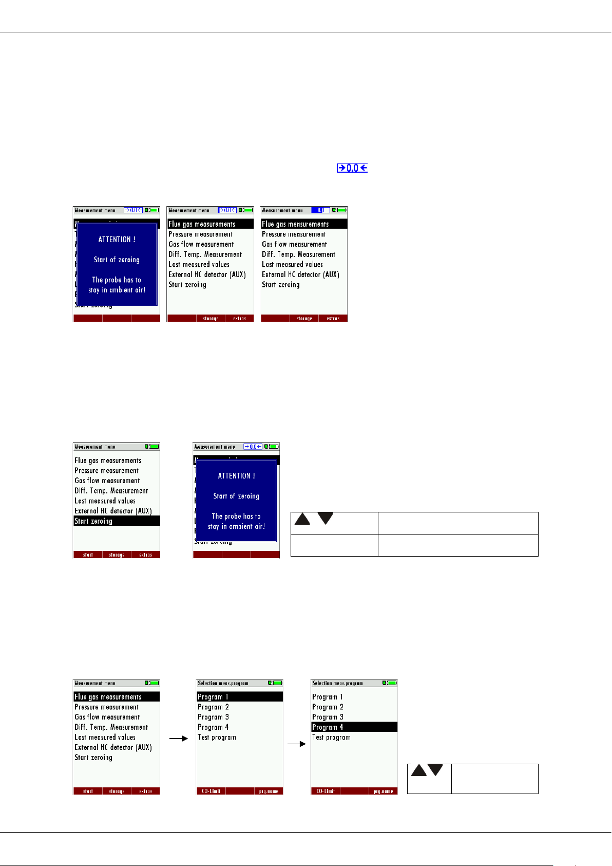
Press the ON key. The analyzer will start zeroing without any further action from the user.
The probe shall NOT be installed in the stack during zeroing!
While the analyzer is zeroing you will see a blinking symbol in the task bar indicating
the progress of zeroing
Once the zeroing cycle is finished the analyzer is ready for measurement.
If any defective sensors will be detected during the zeroing cycle you will get an error message on the display.
Repeating the zeroing
The zeroing can be repeated at any time as long as the probe is not inside the stack. In the
main menu you select “Zeroing”, and after the displayed message press the OK key.
,
OK
7.2. Selection of the measurement program
In the measurement menu select “Flue gas measurements” then select one of the available
programs.
If you press the F1 key “Start” in the measurement menu, you will be directed directly into
the measurement screen, using the parameters (program and fuel type) that have been selected last time the analyzer was used.
MRU GmbH, D-74172 Neckarsulm 25 / 51
, ,
Page 26
7.3. Combustion test
• DANGER
Poisonous gas can be present
NOTE
Wrong measuring results
The core flow search will help you to find the
Temperature rising
ture
The possibility of death through intoxication.
Flue gases are extracted by the analyzer and then evacuated into the ambient air.
► Only operate the analyzer in well ventilated rooms.
The extracted flue gas must be able to evacuate the analyzer without obstruction.
► The exhaust outlet at the rear of the analyzer may never be covered
during a measurement, never operate the analyzer in a transport case.
Operation manual OPTIMA7
7.4. Core flow search
Before using the core flow search it must be switched-on:
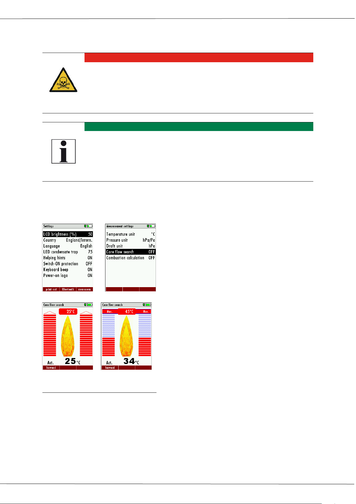
optimal measurement point in the stack. The
core flow can be identified by the maximum
flue gas temperature. In high reaction time
the analyzer displays the trend of the flue gas
temperature. Insert the probe pipe slowly into
the stack and position your probe tube when
F3.
you have reached the maximum flue gas temperature that is displayed
Approaching the maximal flue gas tempera-
Positioning the probe in the core flow:
Insert the probe pipe slowly into the stack and position your probe pipe when you have
reached the maximum flue gas temperature that is displayed (see temperature maximum
value on the display – in this case 45°C).
Maximum temperature has been reached when the arrows (left picture) disappear, max.
(Right picture) appears in place of the arrow, and the beeper signal stops. Moving away
from the max. Temperature will result in the bars moving away from the max. Temperature
(1 bar is equivalent to 1°C). Once the right core flow has been achieved, the probe is fixed
with the probe cone screw.
26 / 51 MRU GmbH, D-74172 Neckarsulm
Page 27
Operation manual OPTIMA7
7.5. Measured value display
After the core flow search you will see the measurement values on the display.
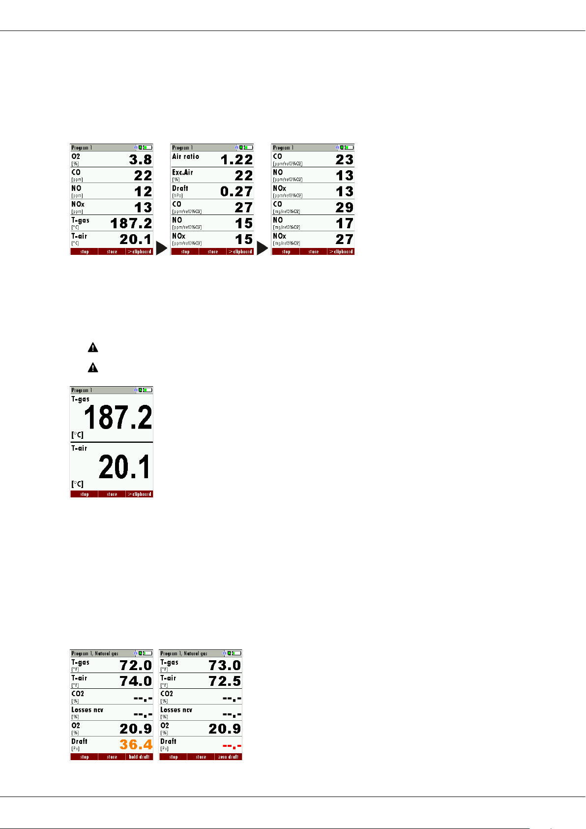
Measurement values can be organized on three pages, each page displaying 6 measurement values.
The order of the display is operator settable.
There are direct measured values available such as Oxygen and Temperature as well as calculated values such as dew point, efficiency and CO2. You will also find the same measurement value in different calculated values such as CO in ppm or CO in mg/kWh.
Values that cannot be displayed are indicated with dashes. Possible reasons for value not
being displayed are:
Electro chemical sensor was detected as defective during zeroing.
External temperature sensors are not connected.
The measurement value T-Gas is usually read at the connector “TGas/AUX” (depending on configuration) or if not available from the connector “T1”.
There are three measurement windows available, with the arrow keys
left and right moving between them.
Zoom function, each with two values, is activated by moving the arrow
keys up and down. Moving arrow keys left and right pages between the
two zoom windows.
7.6. Non-continuous draft measurement
The Optima7 provides for a non-continuous draft measurement. The draft measurement is
disabled when a maximum time after zeroing has elapsed or a significant change in temperature has been detected by the instrument. The maximum time is configured to 10
minutes.
If the draft measurement is disabled it is displayed with “--.-“. The draft measurement can
be enabled again by zeroing the draft: F3 key “zero draft”.
To indicate that the draft measurement is not continuously available it is displayed in colour red.
MRU GmbH, D-74172 Neckarsulm 27 / 51
Page 28
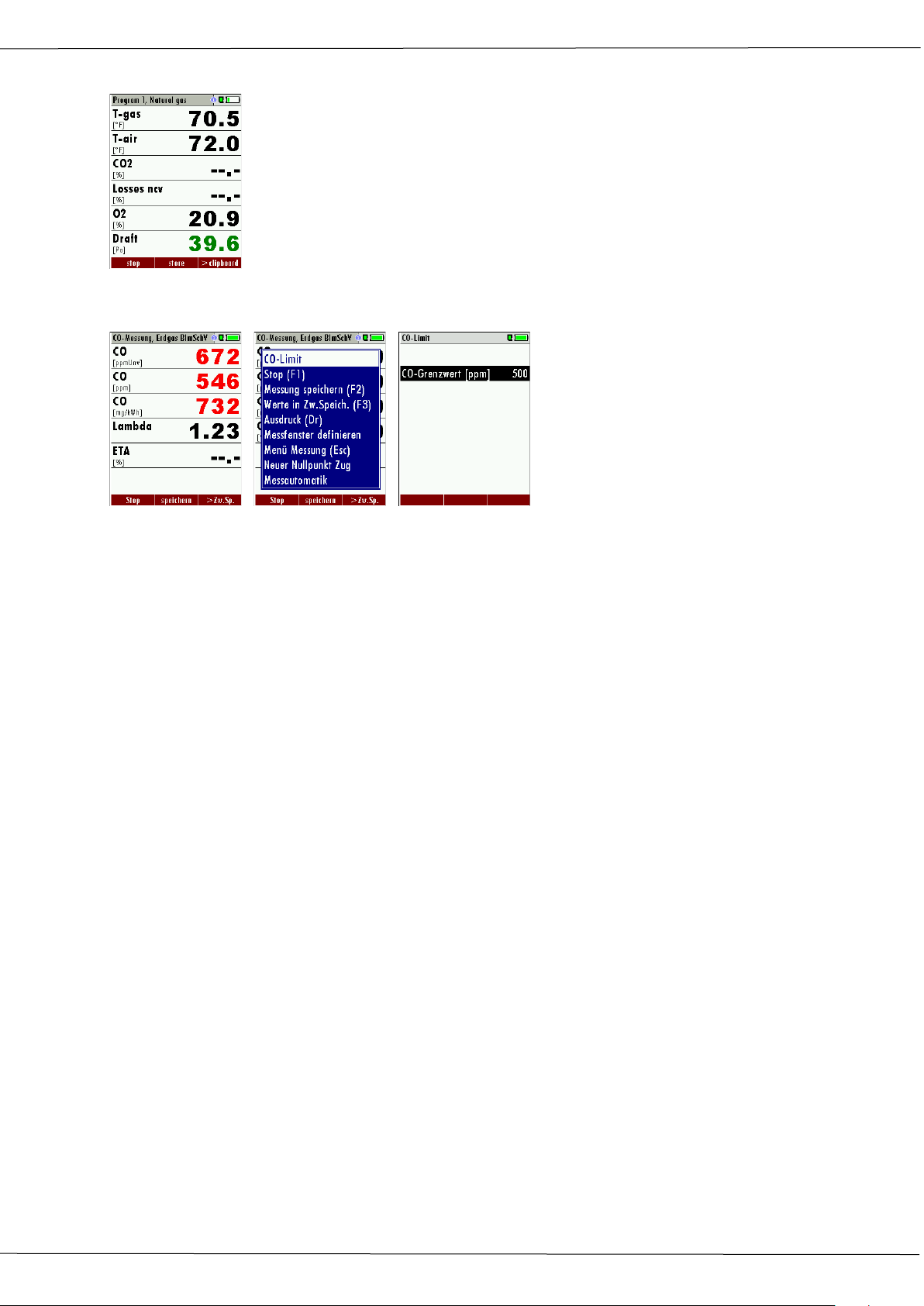
Operation manual OPTIMA7
The user can freeze the draft data by means of the F3 key “hold draft”.
The frozen data is displayed in green.
The unfreeze the measurement one has to exit the menu and enter
again.
All other measurements are processed continuously independent of the
draft measurement status.
7.7. CO-limit (without purging)
If the CO limit value is exceeded, the color of the measured CO values changes (red).
7.8. CO-purging (optional)
If the CO value exceeds the CO threshold, then the measured value is displayed red and air
purging pump is activated. This will protect the CO electrochemical cell from too high CO
gas concentrations.
If the CO value decrease below the CO threshold, then the CO value will be displayed again
in black colour.
Air purging pump is still running and can be deactivated only by accessing the “menu” key
and confirm “purge pump off”
Note: Unit switching: 10000pmm values are displayed in%.
The actual CO value will then be displayed again.
If a measurement with active purging will be stored, the device documented the device
the CO value as CO limit value.
7.9. CO/H2 and CO high (optional)
If that exceeds CO the CO threshold, then to CO high, the measured value is red indicated also the calculated values - is switched.
The CO value exceeds 10.000 ppm to % is in such a way switched (example 1.00%).
If the CO value sinks below the CO threshold, then the red CO value becomes again black
Starting from this moment the purge pump can be switched off over the menu key again.
28 / 51 MRU GmbH, D-74172 Neckarsulm
Page 29
Operation manual OPTIMA7
• CAUTION
HOT – danger of burns and fire hazards from gas extraction probe.
1. Cool down the probe tube.
Before that CO ambient measurement a zeroing at fresh air (out-
Start thereafter the function „CO ambient “at fresh air with the OK
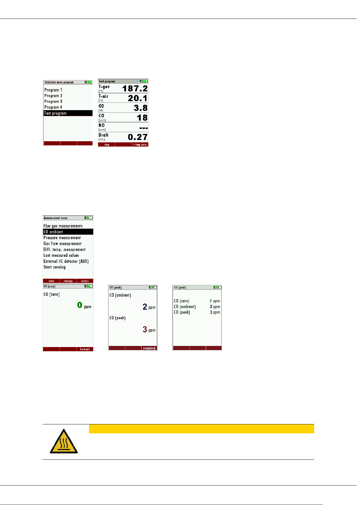
7.10. Test program
This test program is made for testing facilities that will test these analyzers with test gases
and don’t need to make any modifications.
In this program you will only see measured values and no calculated values at all.
7.11. CO-ambient
In some countries the measuring program CO environment is demanded. The objective of
this measuring program is the proof of CO concentration in the environment of the measuring point.
In the case of the country setting in the main menu the menu option is indicated „CO ambient“.
side of the environment of the measuring point) must be taken.
F3 F3
The current CO value (zeroing) as a check is indicated. (This value must be approx. 0 ppm!)
The CO ambient measurement starts through pressing the key F3 at the measuring point.
The current CO (ambient) and CO (peak) values will be indicated.
The measuring result will be indicated by pressing the F3 key. This can be printed out by
the printer-key.
With the ESC key one reaches back in the main menu.
Physical harm and property damage can be caused.
MRU GmbH, D-74172 Neckarsulm 29 / 51
Page 30
Operation manual OPTIMA7
ATTENTION
Thermo-element can be damaged
probe tube and fixate it to protect the thermos-element.
The thermo-element at the tip of the probe tube is very delicate and can
easily be damaged.
2. Once the probe has cooled off slide the probe cone to the tip of the
7.12. Temporary buffer
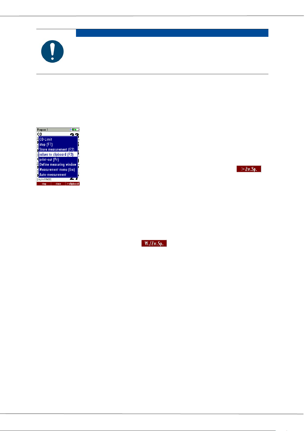
The OPTIMA 7 gives the possibility to set the momentary values into a temporary buffer
during effecting and continuing the measurement. Later on, the values can be brought
back from the temporary buffer to the measuring window in order to print them out or /
and to save them
Set values into temporary buffer
During an actual measurement you can set the actual values into the
temporary buffer
Operation:
1The function „val. to temp. mem.“ of the menu (accessible about the
menu button)
2or, provided that offered, the function key F3 with the text
To bring values back from the temporary buffer
With stopped measurement you are able to change the indicated values with the buffer
content.
Operation:
the function „v./tmp.mem.“ of the menu (accessible about the menu button), or
the function key F3 with the text
Now you can change the current values and the values of the temporary buffer with the
key F3.This change of the actual values with the values of the temporary buffer memory
can be executed several times one after the other
Now it is possible to print and save as usual one of both measurements.
7.13. Storage the measuring results
If in the function key bar "store" is indicated, you can store with the accompanying function key F2 or F3 the measurement in the data memory. The function of the data memory
is explained in chapter 8.
30 / 51 MRU GmbH, D-74172 Neckarsulm
Page 31
Operation manual OPTIMA7
7.14. Printing the measuring results
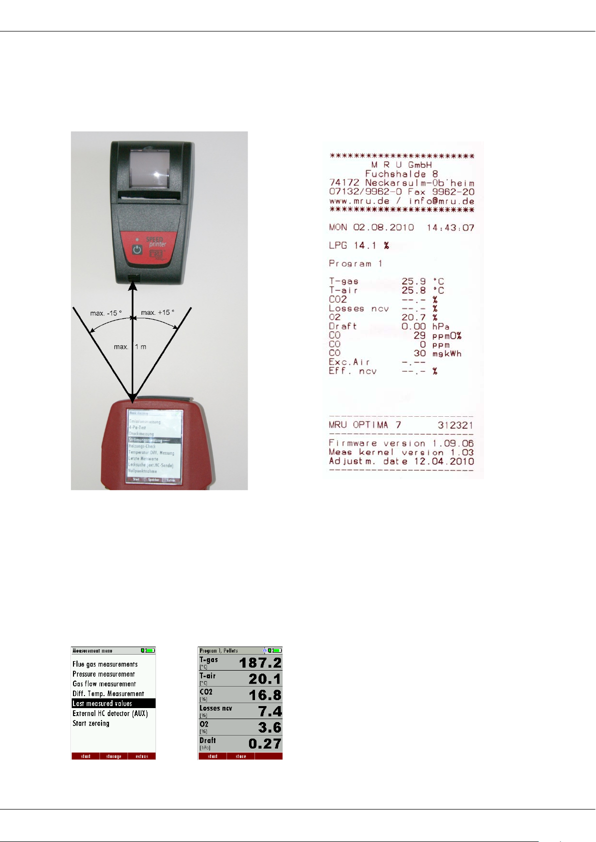
While in the measurement window pressing the printer key will send the information to
the IR printer.
The speed printer (IR desktop printer) Art. No. 62693 must be aligned in addition as follows:
Example: Measurement
All values that can be seen in the measurement window on all three pages will be printed,
double measurement values will only be printed once.
Further technical specifications as well as battery and paper rolls changes please see separate printer manual.
7.15. Last measurement results
The analyzer allows the viewing of the last measurement after a measurement is completed.
In the main menu “Measurement” select the point “last meas. values”.
The last values can be viewed, printed and/or saved.
OK F1
Above the F1 key “Start“instead of “Stop” is displayed. Pressing this key will continue the
measurement.
MRU GmbH, D-74172 Neckarsulm 31 / 51
Page 32
Operation manual OPTIMA7
ATTENTION
Analyzer can be damaged by faulty operation
Select the measurement name 1-4
F1
Save the measured value to one of
F2
Zeroing the pressure sensor
F3
Change the name of the measure-
ESC
Return to the measurement menu
Note:
The pressure sensor can be damaged or destroyed when the supplied
pressure is too high.
► Check the pressure sensor range before applying pressure.
7.16. Pressure measurement
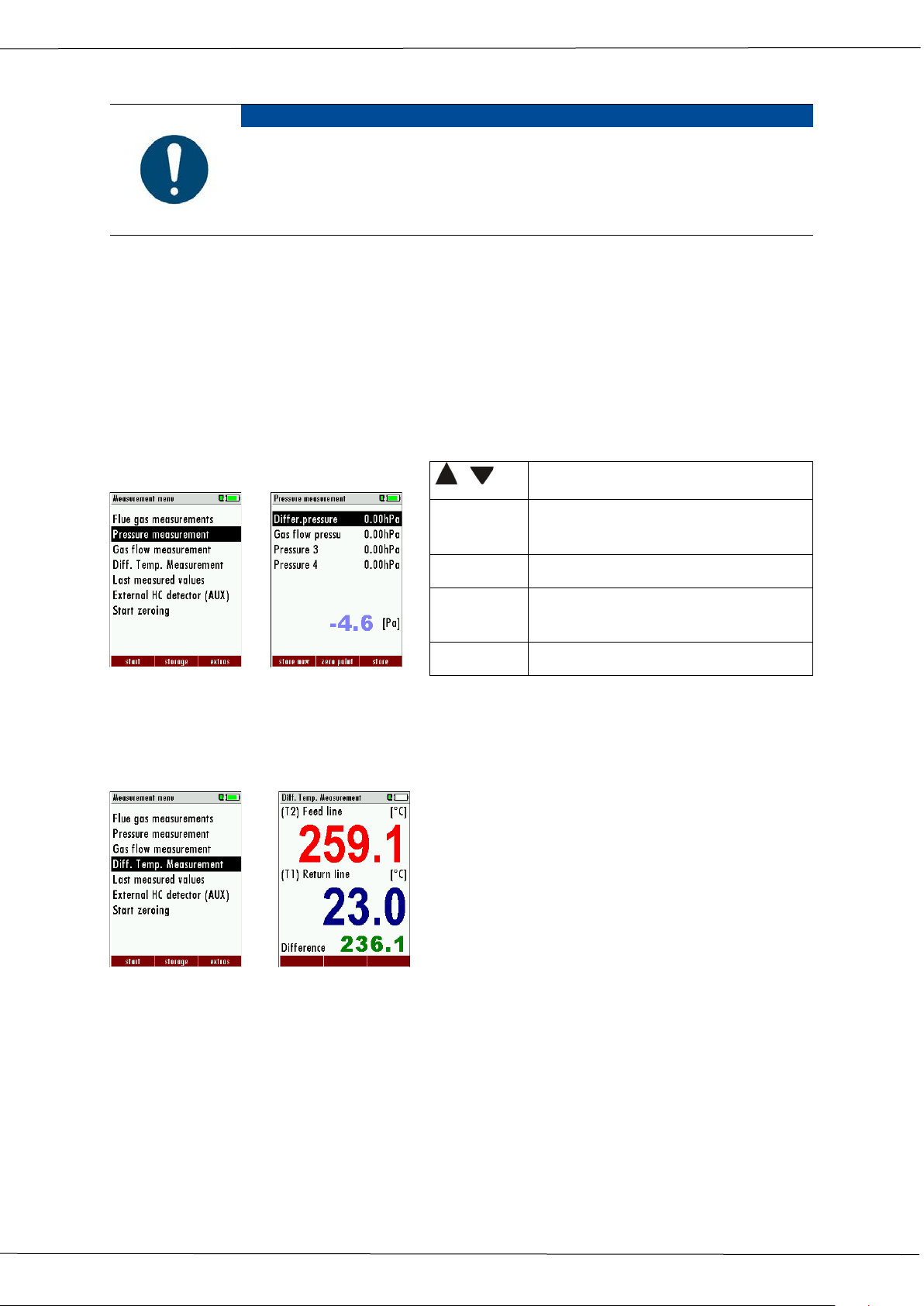
Pressure (4 values) is measured and saved to the selected measurement name. The actual
measured value is displayed in the middle of the display. The 4 measurement names can
be changed as desired.
The hose on the draft + connector must be connected for draft measurements.
The second hose on the Delta P- connector must be connected for differential measurement.
,
the measurement name
ment category
OK
7.17. Differential temperature measurement (optional)
In the differential temperature measurement menu two temperatures can be measured
simultaneously by using the T1 and T2 connectors. Both measured temperatures and the
difference between the temperatures will be displayed.
The accuracy of the difference temperature
measurement is guaranteed only on use of
the MRU temperature sensors.
OK
7.18. Last measured values
The OPTIMA7 offers the possibility to display the last measured values even if they have
not been stored inside the analyzer. In the main menu you select „last measured values“.
You can view the values, print them or store them. These values are erased once you
power down the analyzer.
32 / 51 MRU GmbH, D-74172 Neckarsulm
Page 33
Operation manual OPTIMA7
8 Data Storage
8.1. Data storage organisation
The basis for the data storage of the OPTIMA7 are saved sets of sites inside the analyzer.
Each site has a distinct site number as well as 8 additional free text lines for names and address.
The analyzer can store up to 1,000 different sites.
New sites can be added in the analyzer. Modifications can be done using an external PC
program e.g. MRU Win.
Attention: New sites created in the analyzer will NOT be transferred back to the computer
program. When transferring data from the analyzer to the computer only measurement
data will be transferred, identified by the site number that has been assigned to the measurement, when the measurement was saved.
8.2. Data storage information
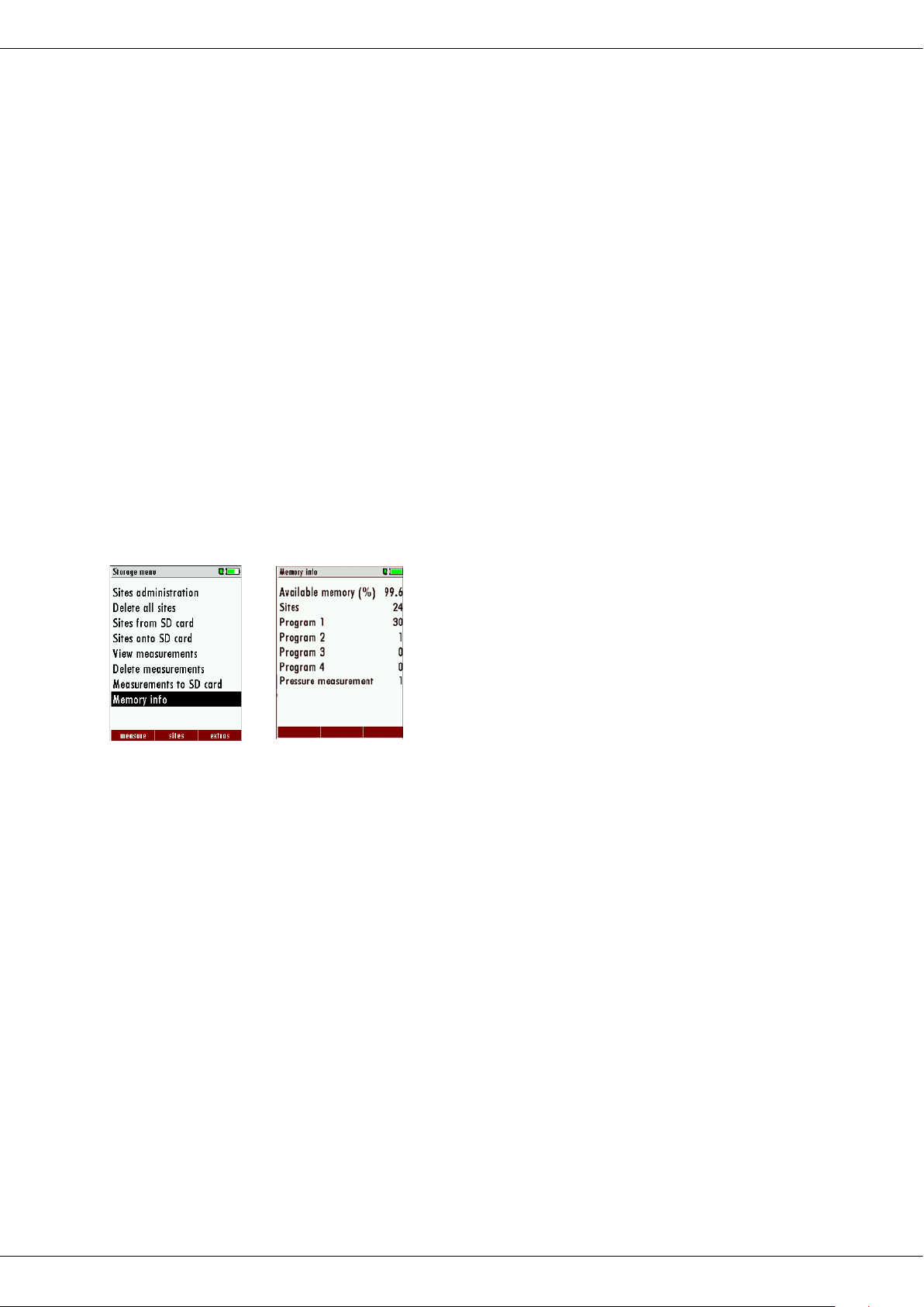
In the menu item "storage" you select „memory info“to get information about the actual
memory volume. The part of free memory, the total number of the stored sites and the
number of the measurements stored all together, split in the kind of the measurement is
listed.
OK
8.3. Sites administration
In the sub menu Sites administration, you can:
• view all data of the stored sites
• create new sites
• change date of existing sites
• delete sites
New sites created in the analyzer will NOT be transferred to a PC program.
View and search sites
In the sub menu Sites administration each site will be displayed with:
• of the unequivocal site number in the first line which is set down because of this
meaning colourfully,
• the other 8 free text lines.
With the arrow keys on the left / on the right you scroll by all sites.
In this menu item, as well as in the menus for viewing the measurements, you can filter
straight after sites by using a search mask.
MRU GmbH, D-74172 Neckarsulm 33 / 51
Page 34
Operation manual OPTIMA7
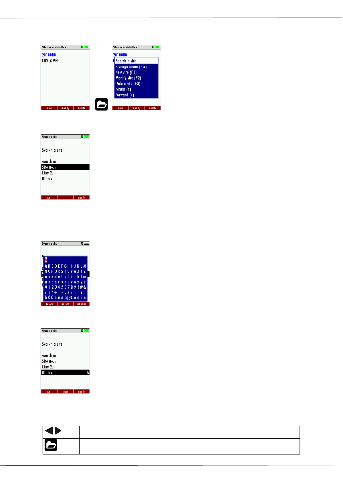
Page through the sites
Menu key: Search site
• select with the menu key "Search a site"
• Now you can enter the text to be searched for the first line, i.e. the site number, or
for the second line, or for the rest of the text lines.
• Select the line for searching (site no. No., line 2, or rests) and select F3 "modify"
• Now in the indicated text input field you can enter a combination of letter, charac-
ter and figures for whose occurence is searched in the selected text field. Press then
„OK“ "
•
• Select after input of the search text F2 = "start"
• If only one site is found as a result of the search, this is displayed. If became several
sites the total number is found in the header viewed and you can scroll by this
found standing with the arrow keys.
34 / 51 MRU GmbH, D-74172 Neckarsulm
Page 35
Operation manual OPTIMA7
ESC
Back to storage menu
, : Selection of the input field
F3: Input mask, see chap. 16.1
F2: Start search
: According to the search criteria found sites page through. If no
saved site with the search criteria agrees occurred the Medung:
„Search unsuccessfully“
8.4. New entry and change of sites
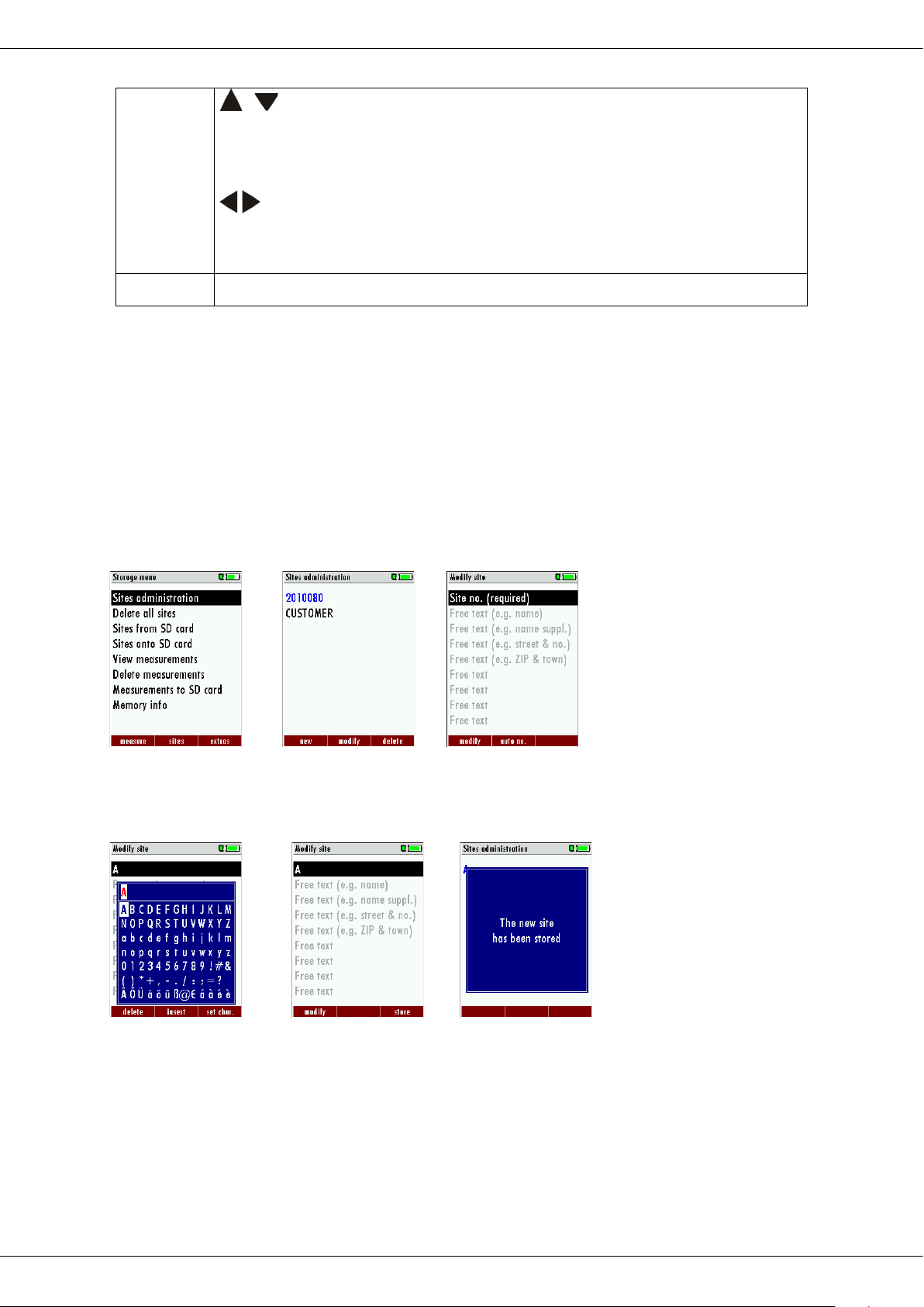
In the menu item "Sites administration" you can new entry sites and change data of existing sites.
Select F1 = "new" for a new site. Besides, it is displayed:
• The first line which must contain an unequivocal site number to the identification
of the site.
With the function F2 = „auto no. “can assign the device automatically a free site
number.
• All further free text lines which can contain, e.g., name and address.
OK F1 F1
In the new site or an existing site you can change the data while you select the too change
line, F1 = "modify" select and use the text input field for editing of the text. Conclude the
text input field with "OK" and store the
updates with F3 = "store".
8.5. Delete sites
You are able to
• delete the displayed sites only by selecting the menu entry "F3" = “delete
• or delete all sites at the same time
MRU GmbH, D-74172 Neckarsulm 35 / 51
or F2 F3
Page 36

Operation manual OPTIMA7
8.6. Data transfer using the SD card
The data exchange format is CSV. A character-separated values (CSV) file is a simple text
format for a database table. Each record in the table is one line of the text file. Each field
value of a record is separated from the next by a character. Optima 7 uses a semi-colon ‘;’
as value separator (other implementations use sometimes a comma). Implementations of
CSV can often handle field values with embedded line breaks or separator characters by
using quotation marks or escape sequences. CSV is a simple file format that is widely supported, so it is often used to move tabular data between different computer programs, for
example Microsoft Excel™ or Access™, that support the format. Also other computer programs offer this type of interface because it is widely spread and easy to use.
The following functions are available from Software Version 1.11 and higher:
• Import of Sites
• Export of Sites
• Export of Flue Gas Measurements
• Export of Differential Pressure Measurements
Import of sites
With this function you can Import Sites which have been created on a computer or another
Analyzer.
The File name must have the name “anlagen.csv“(anlagen = german for sites). The file has
no column heading that means that the first line already has user data. Each line has a minimum of 9 columns (with 8 semi-colons) and the first field in the line will be the site number. All data will be imported as long a site number is available. Per field a maximum of 24
characters will be imported, too long words will be cut off.
Example file with 8 valid sites (4 with 9 lines and 4 with less lines):
A1-Z1;A1-Z2;A1-Z3;A1-Z4;A1-Z5;A1-Z6;A1-Z7;A1-Z8;A1-Z9
A2-Z1;A2-Z2;A2-Z3;A2-Z4;A2-Z5;A2-Z6;A2-Z7;A2-Z8;A2-Z9
A3-Z1;A3-Z2;A3-Z3;A3-Z4;A3-Z5;A3-Z6;A3-Z7;A3-Z8;A3-Z9
A4-Z1;A4-Z2;A4-Z3;A4-Z4;A4-Z5;A4-Z6;A4-Z7;A4-Z8;A4-Z9
A5-Z1;A5-Z2;A5-Z3;A5-Z4;;;;;
A6-Z1;A6-Z2;;A6-Z4;;;;;
A7-Z1;;;A7-Z4;;;;;
A8-Z1;;;;;;;;
Example file with 2 invalid sites (1 with not enough fields and 1 with missing site number):
A1-Z1;A1-Z2
;A1-Z2;A1-Z3;A1-Z4;A1-Z5;A1-Z6;A1-Z7;A1-Z8;A1-Z9
Important:
Whilst importing data from the SD Card to the analyzer there is no check for double site
numbers (Line 1), neither inside of the file that is imported nor between the file and the
sites already inside the analyzer. The analyzer can easily handle double site numbers but
36 / 51 MRU GmbH, D-74172 Neckarsulm
Page 37
Operation manual OPTIMA7
you could face problems with double site numbers when exporting them again to a computer program (see also Export of Measurements).
However the analyzer marks the files that have been imported successfully. If you try to import a file with the same analyzer that is already in the analyzer you will get a red information screen.
Export of sites
This function can be used for an analyzer back up or if you wish to supply the analyzer information to a computer program or another analyzer. This is very handy if you have made
some modifications inside the analyzer (site) for example if you have modified the phone
number of a customer and this modification needs to be updated in the computer software, or if a second analyzer needs to have the same site information.
The File format it’s the same as described above „Import of Sites“.
Only the file name is different, the file name will be ‚ANLxxxxx.csv’, in which the xxxxx are
continuing 5 digit numbers with leading zeros. If the file must be imported into another
analyzer, the file must first be renamed into “anlagen.csv”.
Export of Combustion Tests
This function is used to export the measurements from the analyzer to a computer program.
Attention! This function is not suitable for back up or for the transfer to another analyzer because
the exported file cannot be imported again!
The created file has the name ‚EMIxxxxx.csv’, in which the xxxxx are continuing 5 digit numbers
with leading zeros.
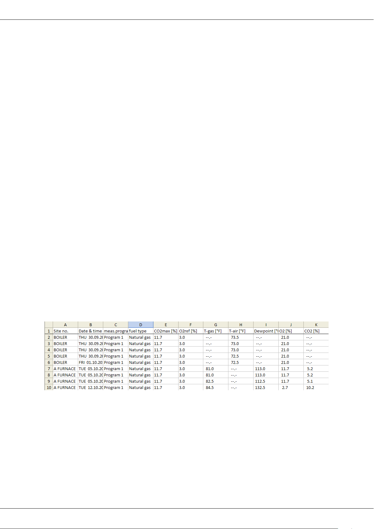
The created file has a column header with the following information: Site number, Date/Time,
Measuring program name, Fuel type, CO2max, O2reference, and all measured values that the analyzer can measure as well as the soot numbers, Derivate and T-Boiler.
Example:
Export of differential pressure measurements
The same function as Export of combustion tests only the file name is different.
The created file has the file name “DDMxxxxx.csv“, in which the xxxxx are continuing 5 digit numbers with leading zeros.
The created file has a column header with the following information: Site number, Date/Time, as
well as 4 saved pressure measurements..
MRU GmbH, D-74172 Neckarsulm 37 / 51
Page 38
Operation manual OPTIMA7
8.7. Measurement in Data storage
View measurement
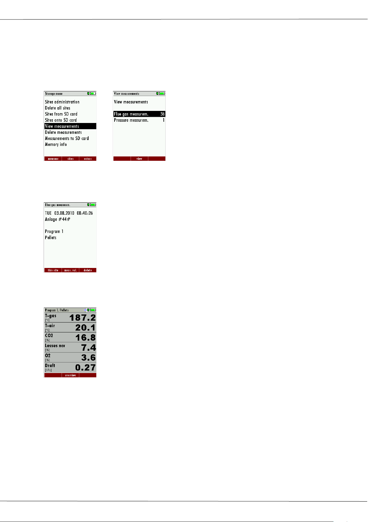
In the menu item „View measurements „you can inspect the stored measurements. After
selection of this item you receive first an overview of the number of the stored measurements according to measuring type.
OK
• Select flue gas measurement or another measuring type.
• Then you receive first a page with context information to the stored measurement.
Scroll with the arrow keys by the context information of the stored measurements.
• With F2 = "measured value" are displayed the measured data of the stored meas-
urement in detail, available in 3 measuring value pages, as they are defined in the
measuring value window.
• With ESC you return to the context information of the measurement.
You have the possibility to display only those data that are assigned to a single site:.
• either F1 = „this site“ , while a measurement of the desired site is displayed.
With F1 = „all sites“ you cancel this filter again.
or while you select with the menu key the function "search a site" and execute, as described in the chapter site administration.
Delete a measurement
You are able to
• delete single measurements, while they are displayed – press the key F3 = "delete" .
38 / 51 MRU GmbH, D-74172 Neckarsulm
Page 39
Operation manual OPTIMA7
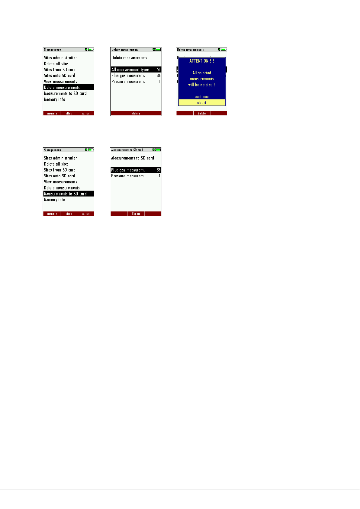
• or delete all measurements of a measuring type.
OK F2
Transfer measurements to the SD card
The OPTIMA 7 offers the possibility to export all stored measurements to a SD card.
OK F2
By confirming with the F2 key the data transmission / export on the SD card is started.
During the data export the display reads „please wait”. A write error to SD card is reported
by the instrument. Make sure that the SD card is not write protected.
The data are stored as a csv-file (e.g., EMI01032.csv) on the SD card. The filename exists of a
sequential number which fixes the device.
This file is editable on your Notebook/PC with a program like e.g. Microsoft® EXCEL or
OpenOffice® Calc.
With possible problems with the using of your computer programs please read your software documentations or ask your software dealer.
MRU GmbH, D-74172 Neckarsulm 39 / 51
Page 40
Operation manual OPTIMA7
9 Extras / Adjustment
The OPTIMA 7 is delivered in a standard software configuration which should cover most
needs. However, there are many ways to tailor the settings to your individual needs if required. The possibilities are highly flexible and individual adaptable.
Use the variable possibilities to adapt your analyzer to your own needs and customize the
measurement menu, the measurement window, the printer output and many other features. Usually this is something you will do once you receive the analyzer, once you have
adapted your analyzer you will most probably don’t make much changes in future, but you
can whenever you need and want to do so.
After you have made any changes in the configuration, you should switch off the analyzer
to save all the changes that have been made. Next time that you start up the analyzer, all
changes will have been made.
9.1. Service calibration menu
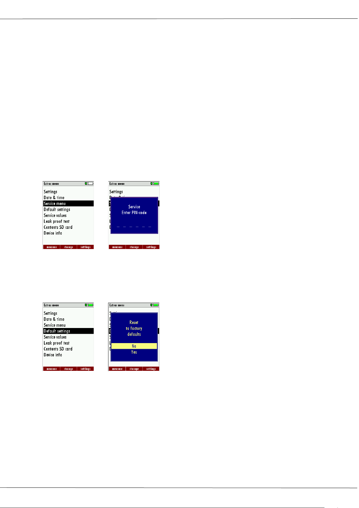
The Maintenance adjustment menu is secured with a Pin Code to protect it against unauthorized users.
OK
If you enter a wrong pin code you will be exited into the “Extra Menu” again.
Please contact MRU GmbH if you need the Pin Code for your analyzer.
Press the Enter key if you should have landed in this menu by accident and you will be exited into the “Extra Menu” again.
9.2. Factory settings
OK
The analyzer will be reset to original delivery settings.
Be aware that your configurations will be deleted, such as:
CO-ppm limits
Fuel type list activation
Measurement window selection and others.
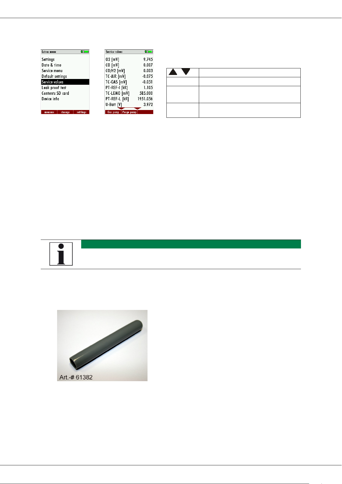
9.3. Service values
Should your analyzer display an error message after zeroing (for example: „O2-Sensor not
OK"), then you can use the Service value menu to get detailed information about possible
defects. In this menu you will see all service values of the sensors and also other parameters.
40 / 51 MRU GmbH, D-74172 Neckarsulm
Page 41
Operation manual OPTIMA7
NOTE
.
,
Jump between the lines
F1
Function test gas pump (on / off)
F2
Function test purge pump (on /
off)
ESC
return
In case of a defect contact the MRU service department. The MRU service technician will
ask you about these values or he will ask you to send them by fax or email.
OK
9.4. Analyzer and accessories leak test
When performing the leak tight test, the complete system including the probe, the sample
line, the condensate separator and the analyzer are checked for leaks. The internal pump
will create a vacuum, this vacuum is measured at the pressure sensor and the result will be
displayed after 10 seconds of testing.
Performing the leak test
With the leak proof test the system is checked by the device (incl. the condensate separator) up to the probe spike on undensity. The internal gas pump generates in addition a sub
pressure which is measured over the built-in draft sensor and is observed for a period of 10
seconds. Based on the decrease of pressure the leakness of the system will be determined.
With dirt and soot particles on the probe tube the test cap will not seal properly
► The probe tip must be cleaned before you start this test!
Operation:
• The leak proof test cap # 61382 (for probe tubes Ø 8 mm) must be put on the probe
spike.
ATTENTION:
The probe spike before the density test clean!
(With depositions on the tube the cap does not
seal.)
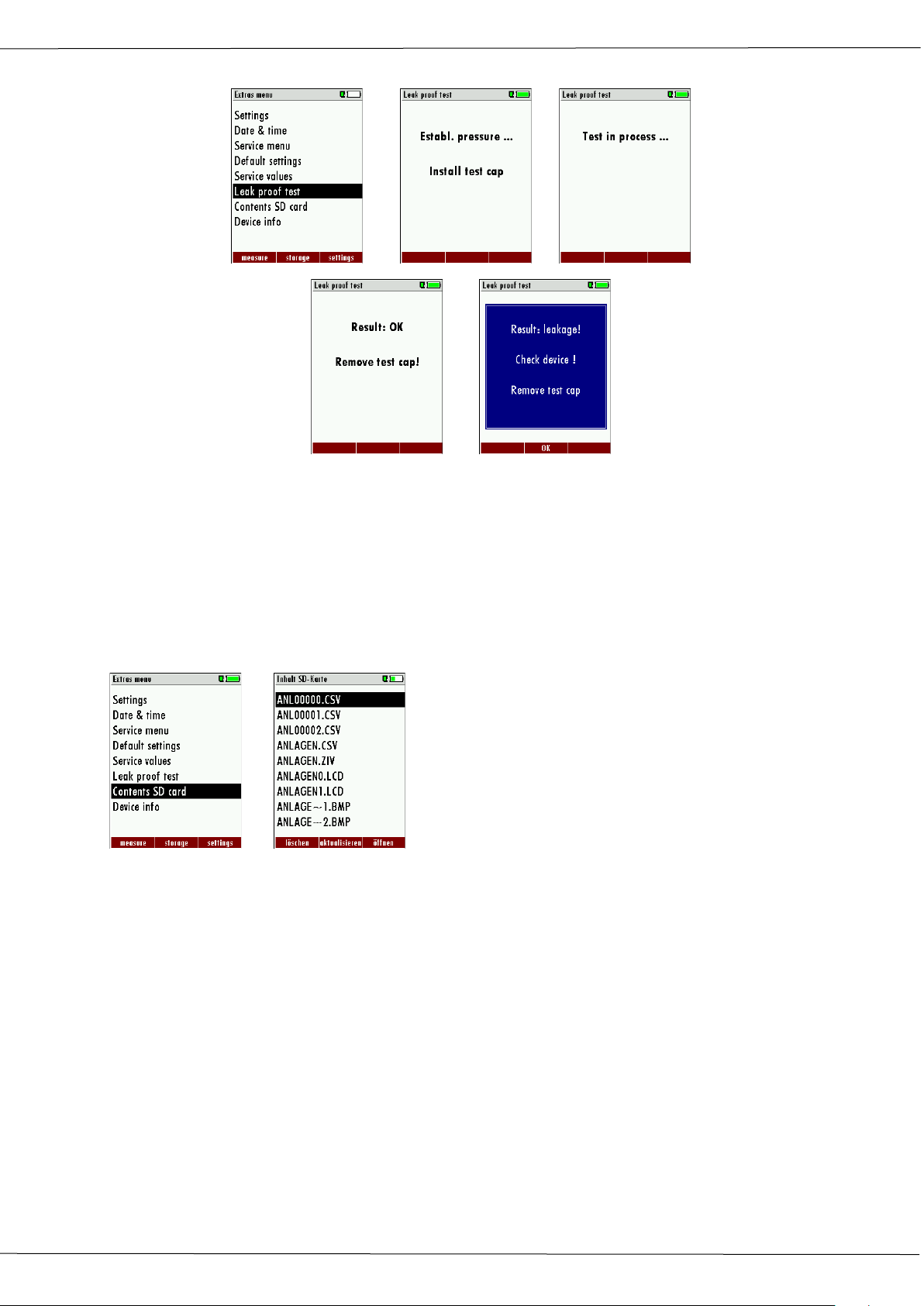
• Launch under “extras” the leak proof test on which the following window will pop
up:
MRU GmbH, D-74172 Neckarsulm 41 / 51
Page 42
Operation manual OPTIMA7
The contents of the SD card will be dis-
OK …
If of the leak proof test is not passed the probe must be checked including the hosing as
well as the condensate separator.
If no undensity is ascertained in these external parts the OPTIMA 7 Combustion Analyzer
has to be checked in a service department
(worldwide service departments see www.mru.eu)
9.5. Contents SD card
played. With F3 the selected file can be
OK
opened.
42 / 51 MRU GmbH, D-74172 Neckarsulm
Page 43
Operation manual OPTIMA7
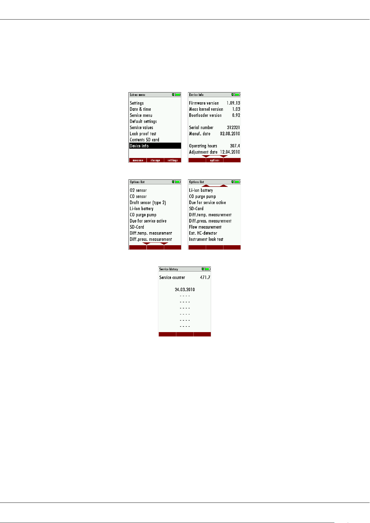
9.6. Contents Analyzer information,
The analyzer information can be viewed in the main menu extras and the sub menu Device info (use context key).
Here you will find information about the analyzer and the installed options.
Press the F2-key to see the installed options.
With the F1-key you get information about the date of the last 7 service procedures
MRU GmbH, D-74172 Neckarsulm 43 / 51
Page 44
Operation manual OPTIMA7
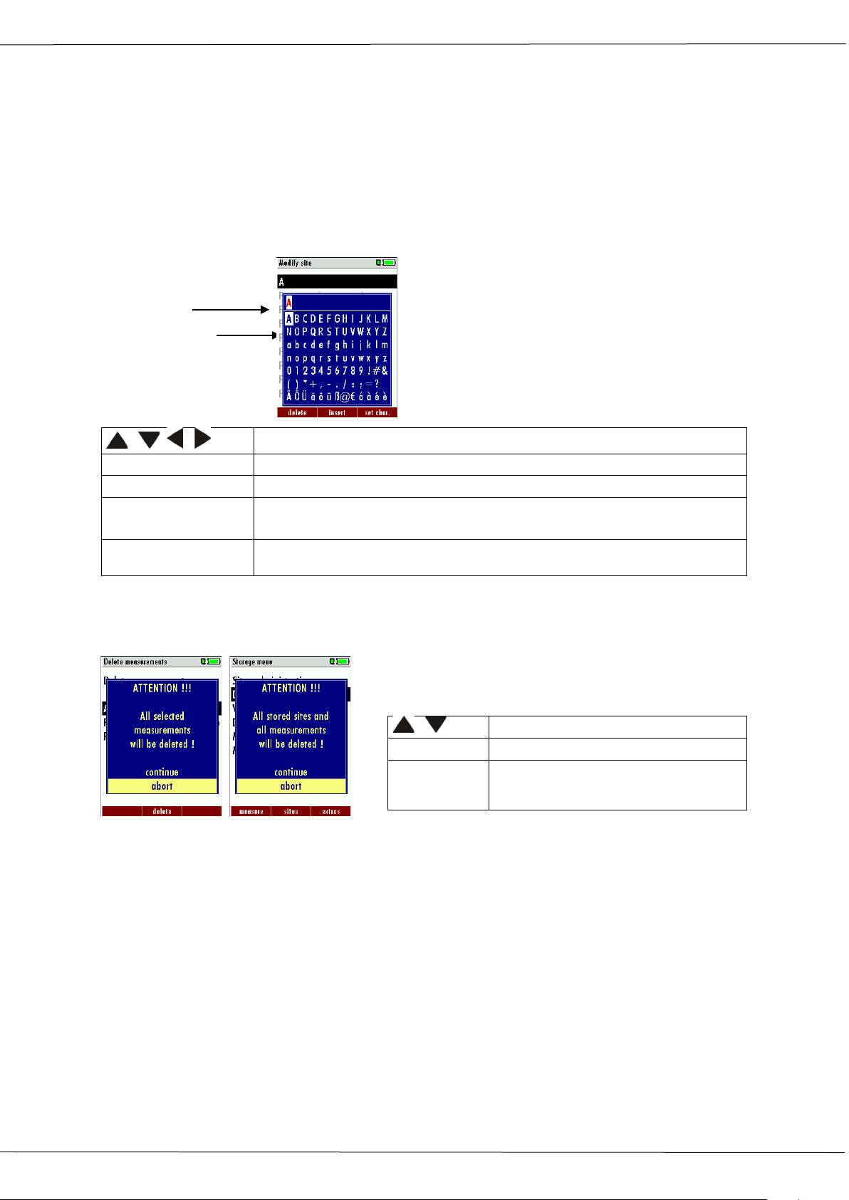
, , ,
Select a letter, number or sign
F1 – delete
The letter left of the cursor will be deleted
F2 – insert
Selected letter or number will be inserted
F3 – over write
Selected letter or number will over write the current letter or number
ESC
Abort the window, changes will NOT be saved
,
Select a line
OK
Confirm the action
ESC
Abort the window, changes will
Insert cursor
10 Appendix
10.1. Text input
A numbers of texts and names can be changed to your own needs.
(For example: the names of the user defined fuel types, site names, the names of the measurement programs)
When you select the text input, the following window will pop up:
Selection cursor
10.2. Asking user for a decision
The OPTIMA 7 will ask you now and then to confirm the action that will be taken.
NOT be saved
,
44 / 51 MRU GmbH, D-74172 Neckarsulm
Page 45
Operation manual OPTIMA7
10.3. Firmware update
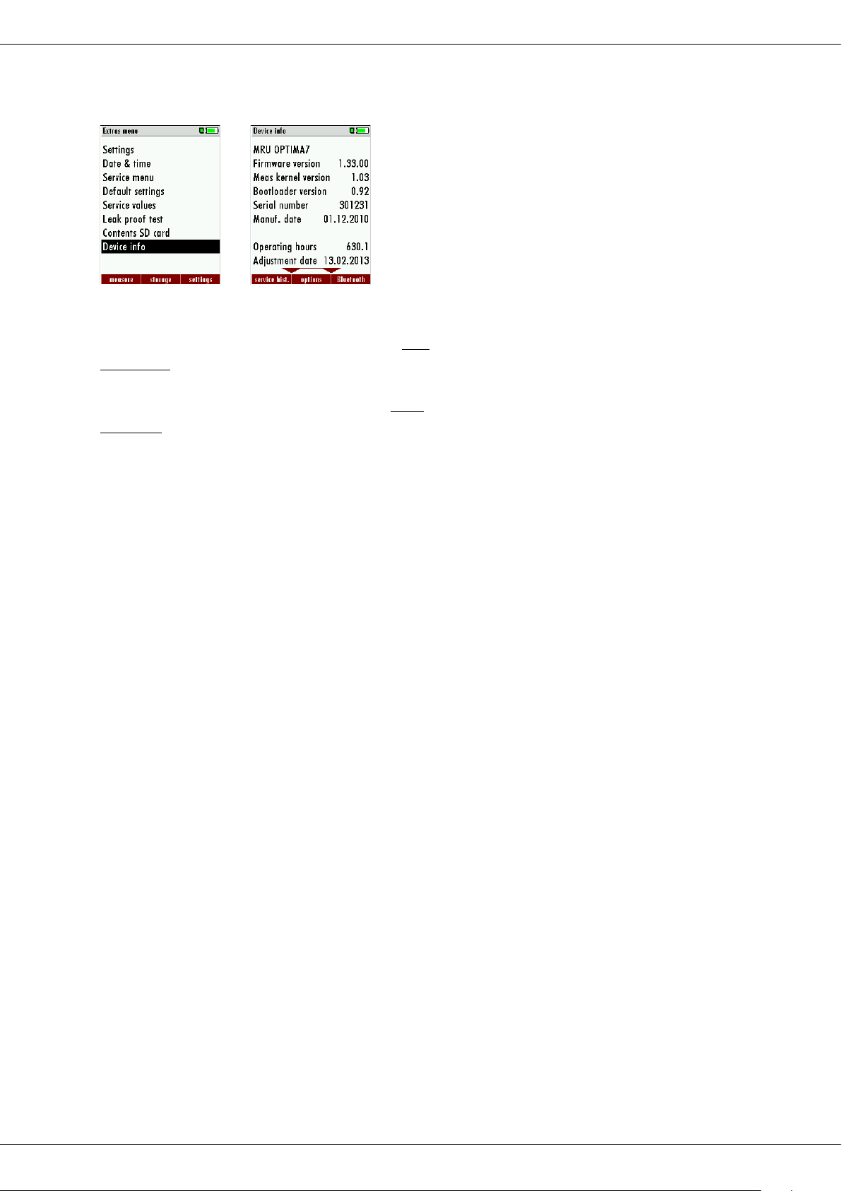
Switch ON the device. Select F3 settings/Device info
OK The first line shows e.g.: Firmware-Version 1.33.00
For the case that there should be problems by the update we need some information of
you.
Please write down your Firmware-Version (e.g.
1.33.00)_________________________________
Please write down your serial number (e.g.
301231)_________________________________
You need the latest file 'All_1083.fwb'. In case you get it in a zip archive you have to extract
it before usage. This file contains all firmware types and the analyser will extract the correct
type out of this file automatically.
Please follow these steps in order to update the analyser:
• copy the file 'All_1083.fwb' to a SD card in the root directory (that means in no di-
rectory)
• switch on the analyser
• insert the SD card into the analyser
• in most cases a message 'Searching firmware, please wait...' will be displayed for
some seconds
• you will be asked: 'Firmware found. Install now?'
• acknowledge with 'install'
• for about 30 seconds the display will be dark, then the analyser will reboot with the
new firmware
• Finished
10.4. Using the USB Port
This port is used for data transfer from your analyzer to your PC / Laptop using the MRU
Online View (Version 2.XX). The first time you want to use your analyzer for data transfer to
your PC or laptop, you have to “mate” the OPTIMA 7 and your PC / Laptop.
Your PC / Laptop will recognize the OPTIMA 7 as USB- HID (Human Interface Device).
Check list:
1. Switch on the OPTIMA 7
2. Connect the USB cable to the OPTIMA 7
3. Connect the USB cable into a free USB port at your PC/Laptop
4. The PC/Laptop must be powered on
5. The above seen information „New hardware found“ will be displayed above the
USB-Icon of your PC/Laptop
MRU GmbH, D-74172 Neckarsulm 45 / 51
Page 46

10.5. Technical data
Measured values
OPTIMA 7
O2
Measurement range
0 - 21,0 Vol-%
Accuracy
± 0,2 Vol-% abs.
Reaction time T90*
< 20 sec
CO2 NDIR
Measurement range
0 - 40 Vol-%
Accuracy
± 0,3 % abs. or** 5 % of the measured value
Reaction time T90*
< 35 s
CH4 NDIR
Measurement range
100 … 40.000 ppm, resolution 10 ppm
Accuracy
± 4 or** 5 % of the measured value
Reaction time T90*
< 35 s
CO (H2 comp.) (optional )
Measurement range
0 - 4.000 ppm, overload up to 10.000 ppm***
Accuracy
± 10 ppm or** 3 % of the measured value up to 4.000 ppm
or** 10 % of the measured value up to 10.000 ppm
Reaction time T90*
< 40 sec
CO low (optional)
Measurement range
0 - 500 ppm, with 0,1 ppm resolution
Accuracy
± 2,0 ppm or ** 5 % reading
CO high (optional)
Measurement range
0 - 4.000 ppm, overload up to 20.000 ppm***
Accuracy
± 100 ppm or** 5 % of the measured value up to 4.000 ppm
or** 10 % of the measured value up to 20.000 ppm
Reaction time T90*
< 40 sec
CO very high (optional)
Measurement range
0 – 4,0 %, overload up to 10 %
Accuracy
± 0,02 or** 5 % of the measured value up to 4,00 %
or** 10 % of the measured value up to 20.000 ppm
Reaction time T90*
< 40 sec
NO (optional)
Measurement range
0 - 1.000 ppm, overload up to 5.000 ppm***
Accuracy
± 5 ppm or** 5 % of the measured value up to 1.000 ppm
or** 10 % of the measured value up to 5.000 ppm
Reaction time T90*
≤ 30 sec
NO low (optional)
Measurement range
0 - 300 ppm, with 0,1 ppm resolution
Accuracy
± 2,0 ppm or ** 5 % reading
NO2 (optional)
Measurement range
0 - 200 ppm, overload up to 1.000 ppm***
Accuracy
± 5 ppm or** 5 % of the measured value up to 200 ppm
or** 10 % of the measured value up to 1.000 ppm
Reaction time T90*
≤ 60 sec
SO2 (optional)
Measurement range
0 – 2.000 ppm, overload up to 5.000 ppm***
Accuracy
± 10 ppm or** 5 % of the measured value up to 2.000 ppm
or** 10 % of the measured value up to 5.000 ppm
Reaction time T90*
≤ 40 sec
Operation manual OPTIMA7
46 / 51 MRU GmbH, D-74172 Neckarsulm
Page 47

Operation manual OPTIMA7
H2S (option)
Measurement range
0 – 500 ppm, overload up to 2.000 ppm***
Accuracy
± 5 ppm or** 5 % of the measured value up to 500 ppm
or** 10 % of the measured value up to 2.000 ppm
Reaction time T90*
≤ 60 sec
Flue gas temperature TA
Measurement range
0 - 800 °C with high grade steel probe pipe
Measurement range
0 - 1.100 °C with Inconel probe pipe
Accuracy
± 2 °C ≤ 200 °C
1 % of the measured value > 200 °C
Ambient air temperature TL
Measurement range
0 - 100 °C
Accuracy
± 1 °C
Draft
Measurement range
± 200 hPa
Accuracy
± 0,02 hPa or** 1% of the measured value
Differential pressure
Measurement range
± 100 hPa
Accuracy
± 0,02 hPa or** 1% of the measured value
Max suction range gas pump
150 hPa
Typical gas flow
60 l/h
Calculated values
(Fuel type dependent)
CO2
Measurement range
0 - CO2 max
Accuracy
± 0,3 Vol-% abs.
Air ratio
1 - 20
Excess Air
0 - 999 %
PI (Poison Index / Ratio)
0.0001 - 10.0
Dew point
°C
Losses qA
0 - 99,9 %
Efficiency ή
0 - 120 %
Measurement values as
mg/Nm3, O2 in relation, mg/KWh, NOx as mg/Nm3 NO2,
CO/CO2 ratio
General specification
Operating temperature
+ 5 - + 45 °C /+41 ... + 113° F, max. 95 % RH, not condensing
Storing temperature
- 20 - + 50 °C / - 4 ... + 122° F
Power supply
Internal: LI-Ion battery pack 20 h operation time
External: wall-plug grid power supply, 100 - 240 V AC / 5,0 Vdc /
1200 mA / 50 … 60 Hz
Weight
ca. 750 g / approx. 1.65 lbs (with 2 sensors)
Sizes
244 x 113 x 54 mm / 4.3” x 8.8” x 2.04”
* = typical sensor value, ** whichever is larger,
***only for SHORT-TERM measurement
Technical changes possible
at any time!
Rev date: 20180814
MRU GmbH, D-74172 Neckarsulm 47 / 51
Page 48
Operation manual OPTIMA7
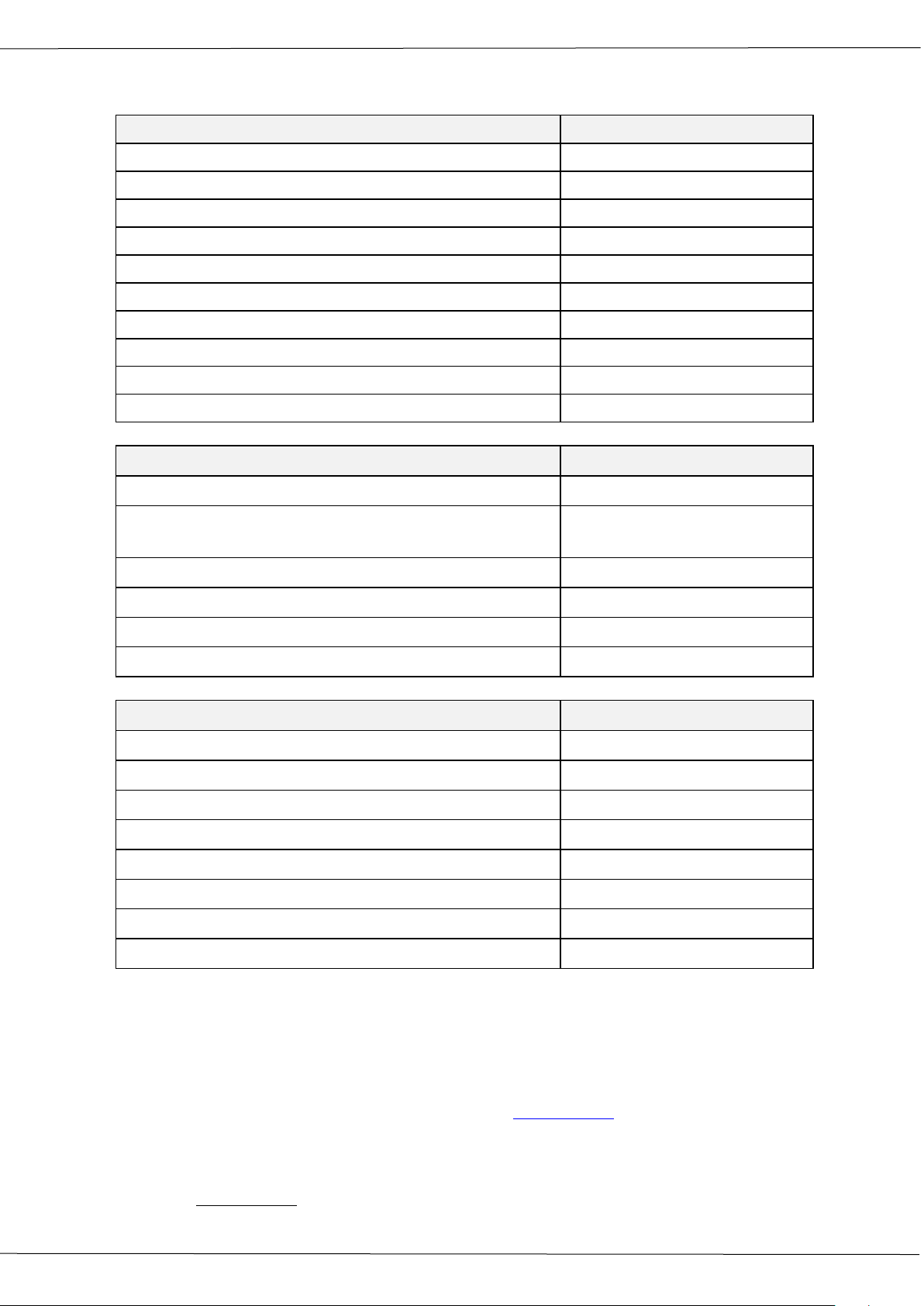
Analisis and calculations
Measured values Unit
O2 [%]
CO [ppm]
CO [%]
NO [ppm]
NO2 [ppm]
SO2 [ppm]
Temp. Ambient air (Thermo-Element) [°C] [°F]
Temp. Flue gas (Thermo-Element) [°C] [°F]
CO [ppm]
Draft [hPa]
Available conversions of CO CO
[ ppm ] related to. on 0% rest O2 (undiluted) X
[ ppm ] related to. on fuel type dependent O2 reference
X
value
[ mg/m3 ] X
[mg/kWh] X
[mg/MJ] X
[ mg/m3 ] on fuel type dependent O2 reference value X
Continously caculated values Unit
CO2 [%]
Efficiency ETA [%]
Efficiency condensed [%]
Losses [%]
Losses condensed [%]
Lambda -
Dew point [°C] [°F]
CO/CO2 ratio [%]
Losses and efficiency are calculated by means of net calorific value.
These values are than referenced for the gross calorific value for condensing boilers only.
(Efficiency > 100)
The calculations of efficiency and exhaust losses are performed using Siegert’s formula.
For further information please contact MRU GmbH. (www.mru.eu)
10.6. Fuel type list
Fuel types for different countries can be obtained from MRU GmbH:
Web page: www.mru.eu
48 / 51 MRU GmbH, D-74172 Neckarsulm
Page 49

1. Effect
2. Error indication
3. Cause
4. Solution
Device cannot be
LED behind the con-
Device does not
Press ESC and ON sim-
Inside of the device is
Display indication:
e.g. device was
Put the device to a
Measuring values are
Sensors already
Vent device with fresh
No measurement
Device cannot be
Connect the device to
Measurement with-
Temperature indica-
Thermoelement
Call our after-sales ser-
Wrong measuring
Measuring range ex-
Connection probe
Effect tightness test!
Wrong measuring va-
Gas temperature is
Probe is not
Check probe plug re-
10.7. Troubleshooting
Troubleshooting your analyzer
Operation manual OPTIMA7
switched off by pressing the OFF key.
too cold, device not
ready for operation.
not correct
possible
densate separator is
on and the LCD display is dark
“Device too cold” or
audible sound every
5 sec..
react on any key.
stored in a cold
place during winter.
get in tough with
the gas during calibration.
switched on or
does not react after being switched
on.
ultaneously!
EMERGENCY OFF
After this, the date
and time have to set
new.
warm room and wait
air and re-start!
the line power in order to charge the battery.
out exact temperature values.
values
lues
tion:
- - - , - °C
ceeded:
Value O2 too high
Values CO and CO2
to low
too hot or alternates
Battery discharge
defective, balancing network interrupted or not connected.
– device not correct. Leakage at
probe / tube / condensate separator,
pump does not
suck correctly
plugged in correctly, defective
cable in the probe
line, formation of
condensate at the
probe tip.
vice.
Remove probe from
the gas duct and condensate from the
probe tube.
By visual control of
probes, tubes condensate separator, leaking
parts could be found.
spectively probe line
regarding damages
(loose connection), remove condensate
from the probe tip.
MRU GmbH, D-74172 Neckarsulm 49 / 51
Page 50

Operation manual OPTIMA7
1. Effect
2. Cause
3. Solution
Dirt and / or humidity inside
Fine filters are wet and / or
Check filters more often
Wrong measuring values
Cover, intermediary unit,
Check tightness with every
Troubleshooting the condensate separator
the device
No filter effect
Sensor failure
Pump failure
dirty.
plexiglass tube and locking
pieces are not tightly fixed
respectively screwed
Renew them if necessary
(white = OK)
Brown-black = renewal
filter change.
50 / 51 MRU GmbH, D-74172 Neckarsulm
Page 51
Operation manual OPTIMA7
10.8. Declaration of conformity OPTIMA7
MRU GmbH, D-74172 Neckarsulm 51 / 51
 Loading...