

Page 1
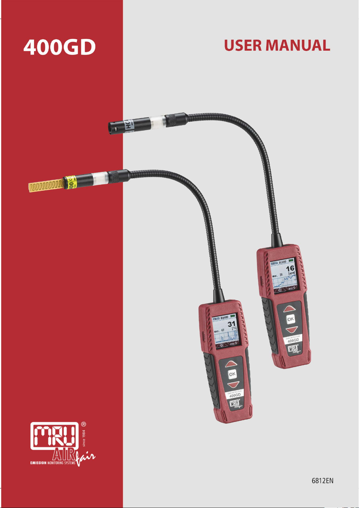
USER MANUAL
400GD
MRU GmbH, D-74172 Neckarsulm 1 / 20
Page 2

USER MANUAL
Manufacturer:
400GD
Legal notices / Intellectual property rights comments
Original user manual
© 2019 by MRU
No part of this manual may be published in any form (print, photocopy,
electronic media or any other publication form) without a written approval
by the publisher.
All user trademarks and name mark descriptions, even those which are not
marked as such, are properties of the respective owners.
Edition: 2019-05-20, V03
2 / 20 MRU GmbH, D-74172 Neckarsulm
Page 3

USER MANUAL
400GD
Content
1 Introduction ........................................................................................... 4
1.1. Intended usage .................................................................................................... 4
1.2. The company MRU .............................................................................................. 5
2 Security and safety directions for the analyzer .................................. 6
2.1. Safety manual ....................................................................................................... 6
2.2. Safety manual ....................................................................................................... 6
3 Description ............................................................................................. 7
3.1. Purpose ................................................................................................................... 7
3.2. The Analyzer .......................................................................................................... 8
3.3. User interface ........................................................................................................ 8
3.4. Menu structure ..................................................................................................... 9
4 Operation ............................................................................................ 10
4.1. Commissioning ................................................................................................. 10
4.2. Power up – analyzer without sensor .......................................................... 10
4.3. Power down ....................................................................................................... 10
4.4. Auto-off function .............................................................................................. 10
4.5. Reset ...................................................................................................................... 10
5 Measuring............................................................................................ 11
5.1. Power supply ...................................................................................................... 11
5.2. Battery status indicator ................................................................................... 11
5.3. Measurement ..................................................................................................... 11
5.4. Measurement example with the HC-sensor HC400 .............................. 11
5.5. QR-Code ............................................................................................................... 13
6 Maintenance and care ........................................................................ 15
6.1. Maintenance....................................................................................................... 15
6.2. Care ....................................................................................................................... 15
6.3. Care hints for sensors ...................................................................................... 15
7 Appendix ............................................................................................. 16
7.1. Technical data .................................................................................................... 16
7.2. Sensors ................................................................................................................. 16
7.3. Service menu ...................................................................................................... 19
8 Declaration of conformity .................................................................. 20
MRU GmbH, D-74172 Neckarsulm 3 / 20
Page 4

USER MANUAL
This analyzer meets the requirements of the
400GD
1 Introduction
This manual is an important part of your delivery. It explains the us-
age and purpose of the MRU Multi-Gas detector 400GD.
Please read this manual carefully and make yourselves familiar with the
400GD before using it.
The GD400 may only be used by skilled personnel and may only be
used for its intended purpose.
Please pay special attention to the security and warning signs, to avoid
personal injuries and damaging the product.
MRU can’t be held responsible for damages or injuries, by mot following the
instructions in this manual.
Always keep the manual near you when working with the analyzer, to
be able to read instructions as needed.
1.1. Intended usage
The multi-purpose GD400 is available with different interchangeable sensor
heads and can be used:
Gas Leak detector to detect gas leaks in an installation area
Spillage test to locate leaks at flue pipes
The analyzer detects measurement components and displays them.
The instrument was manufactured according relevant norms and regulations. It must be used within its intended use.
The analyzer may not be modified from the design or safety engineering.
Modifications of any kind by the user will render the declaration of con-
formity.
valid European and national regulations.
You can find the declaration of conformity in the
appendix.
4 / 20 MRU GmbH, D-74172 Neckarsulm
Page 5
USER MANUAL
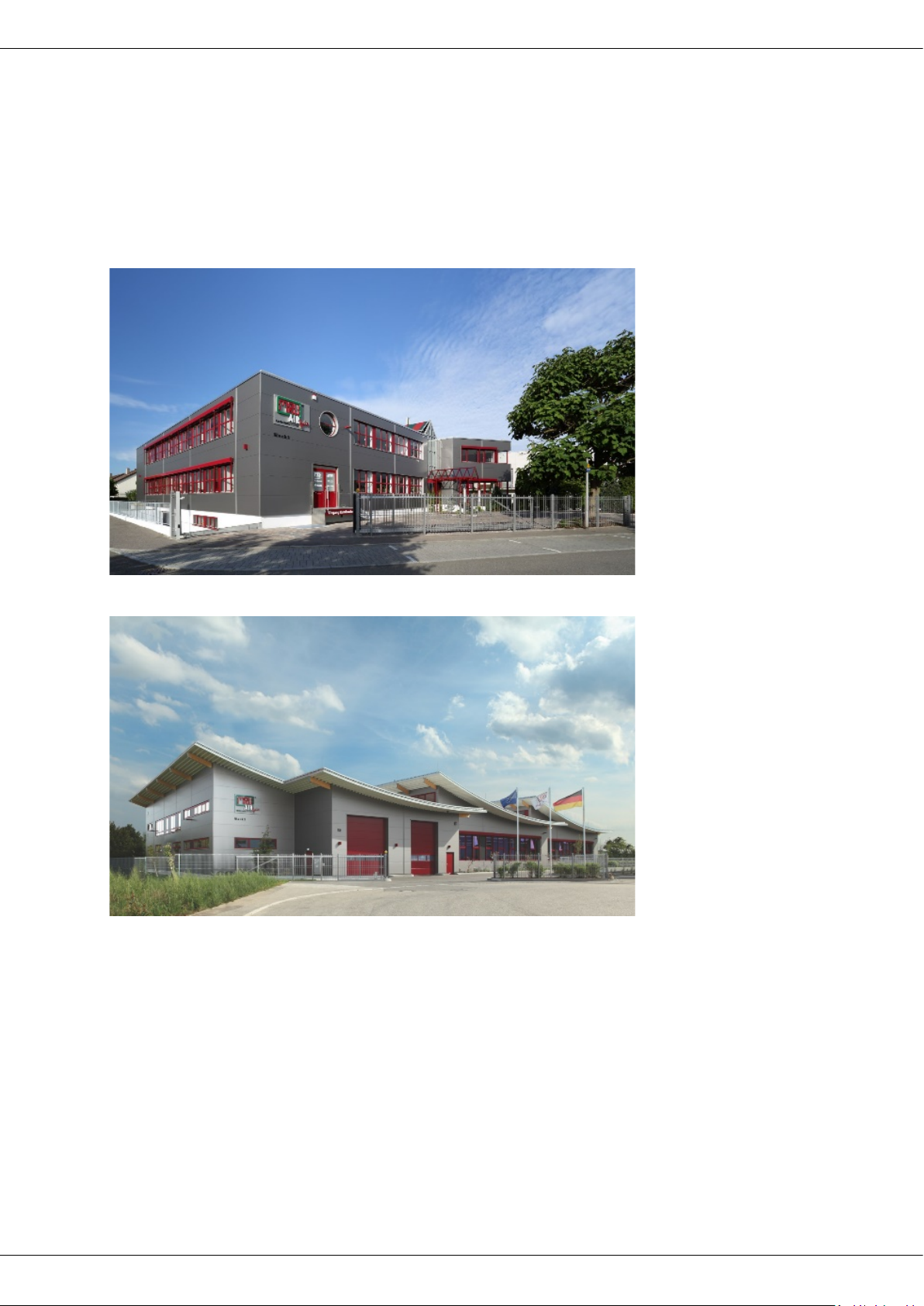
Plant 1: Sales, Service, R&D
Plant 2: Production
400GD
1.2. The company MRU
The 400GD is manufactured by the MRU GmbH in Neckarsulm, Germany
(founded in 1984), a medium sized company that specializes in developing,
producing and marketing high quality emission monitoring analyzers. MRU
GmbH manufactures a wide range of instruments, from standard analyzers
up to tailor made industrial analyzers
MRU GmbH
Fuchshalde 8 + 12
74172 Neckarsulm - Obereisesheim GERMANY
Phone +49 71 32 99 62 0 (Front office)
Phone +49 71 32 99 62 61 (Service)
Fax +49 71 32 99 62 20
Email: [email protected]
Internet: www.mru.eu
MRU GmbH, D-74172 Neckarsulm 5 / 20
Page 6

USER MANUAL
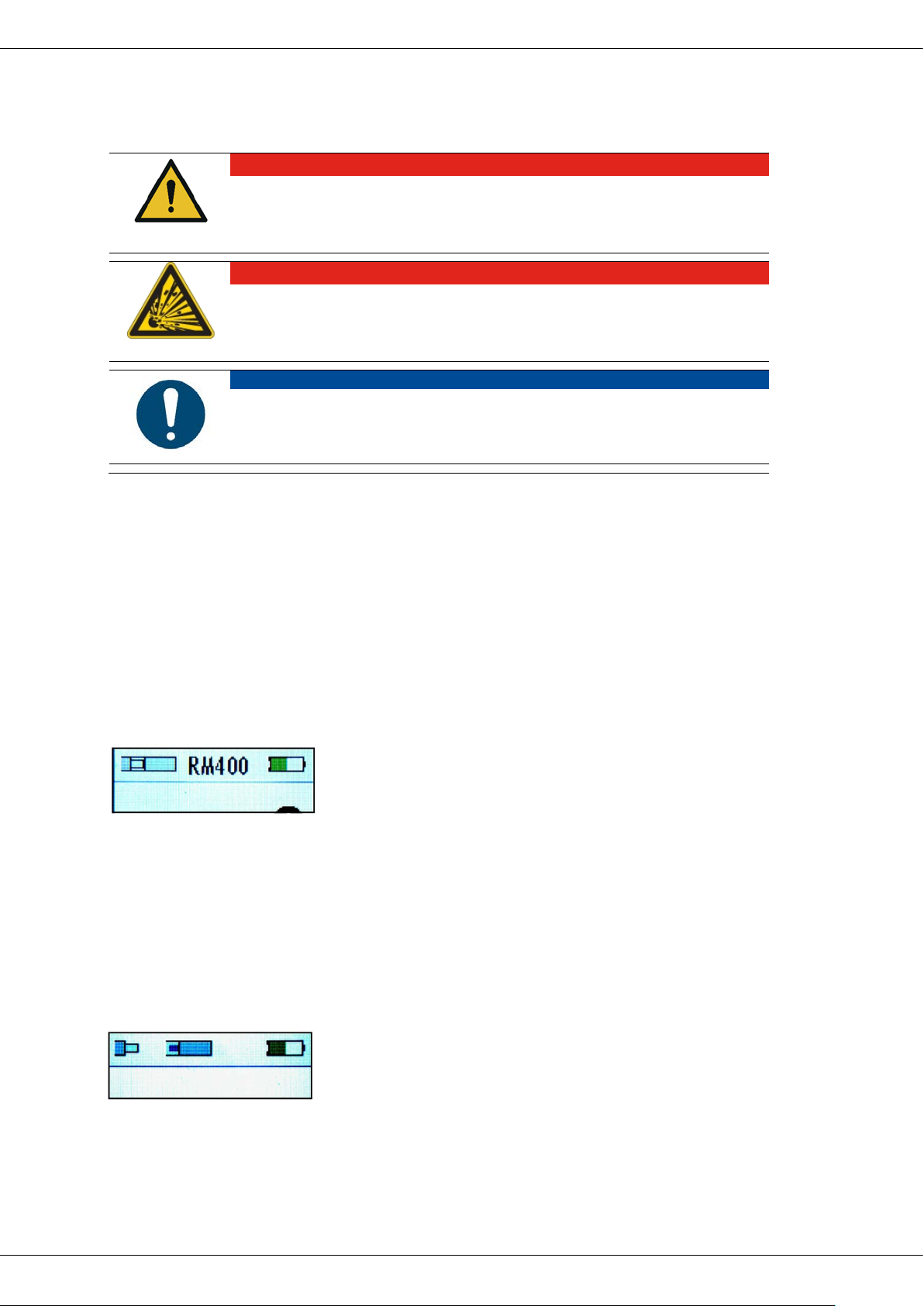
DANGER
WARNING
CAUTION
ATTENTION
NOTE
Identifies user tips and other especially important information.
400GD
2 Security and safety directions for the analyzer
2.1. Safety manual
All general information and safety precautions of MRU products are listed in
the supplied separate safety manual.
Therefore, this manual must be read and observed before the first use of
the analyzer.
Instrument-specific safety and warning requirements in this manual are prefixed before dangerous actions
2.2. Safety manual
The used categories of safety precautions are here explained once more
Identifies an immediate, impending hazard that, if ignored,
will result in severe bodily injuries or death.
Identifies an immediate, impending hazard that, if ignored,
may result in severe bodily injuries, material damage or
death.
Identifies a possibly dangerous situation that, if ignored,
may result in minor injuries.
Identifies a possibly harmful situation that, if ignored, may result in damages to the device or its surroundings.
6 / 20 MRU GmbH, D-74172 Neckarsulm
Page 7

USER MANUAL
400GD
3 Description
3.1. Purpose
The main purpose of the 400GD multi-gas detector in combination with
the exchangeable sensor heads is the detection of gases and flue gases in
boiler rooms / heating installations and test:
Surface mounted gas pipes
Check ambient air for combustible gases
Inspect manholes and cavities
Soundness of combustion systems
The 400GD can be used for other measuring tasks.
Interchangeable sensors:
HC-sensors to detect leaks at gas pipes.
Humidity sensor RM400 to detect leaks at flue pipes.
Condensing humidity sensor RM400 for spillage tests on flue gas systems
Infrared temperature sensor IR400 for contactless measurement of surface
temperature
Hygrometer sensor HM400 for the check of indoor climate
Refrigerant detector RF400 for leak detection on air conditioning units
Visit our webpage www.mru.eu to see available options or talk to your MRU
representative.
MRU GmbH, D-74172 Neckarsulm 7 / 20
Page 8
USER MANUAL
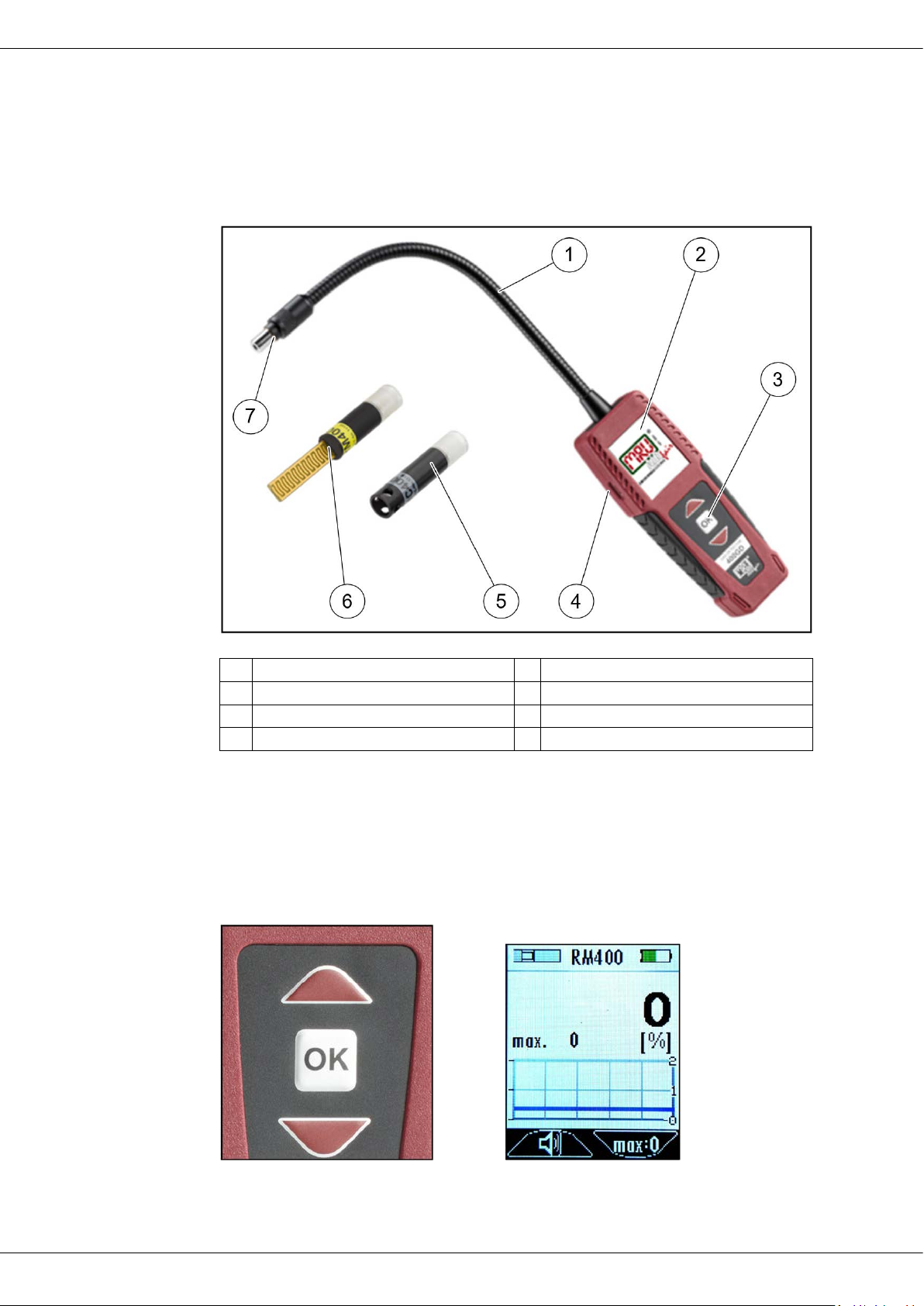
1
Flexible arm
2
Display
3
Keypad
4
Mini-USB port
5
HC sensor HC400 (option)
6
Humidity sensor RM400 (option)
7
Sensor connector
3.2. The Analyzer
The analyzer has a compact and sturdy fiber glass reinforced enclosure.
The analyzer is operated using the key pad and values are displayed on the
color display.
400GD
3.3. User interface
All functions are being displayed on the analyzer display.
Operation is done using the keypad. “Below” each menu and displayed
screen, there are submenus available.
Keypad Start screen Measurement
8 / 20 MRU GmbH, D-74172 Neckarsulm
Page 9

USER MANUAL
Start
Start a measurement
ON
Power down
Set Zero
Set to zero (for HC400)
Display
Display contrast, adjustable 25; 50; 75; 100%
Volume
Alarm volume, adjustable 25; 50; 75; 100%
Alarm
Alarm threshold, adjustable in steps of 10
Service
Status vales (Battery, USB ...)
Sensor
Values of the inserted sensor
Info
Information about the analyzer
400GD
3.4. Menu structure
All functions are available in the EXTRAS menu. After start up the measurement screen is available. You will navigate between menus using the arrow keys and OK key.
MRU GmbH, D-74172 Neckarsulm 9 / 20
Page 10

USER MANUAL
Press ANY key to stop the count-
400GD
4 Operation
4.1. Commissioning
The analyzer has been factory assembled, has been calibrated and is ready
to be used.
Check the instrument regarding condition and integrity after delivery.
Charge the internal battery for at least 8 hours, ☞ see 5.2.
4.2. Power up – analyzer without sensor
Press and hold the OK key for at least 3 seconds.
The MRU start screen appears.
You are asked to connect a sensor.
Connect the sensor ☞ see 5.2
The warm up phase is displayed (only HC400)
The measurement menu is being displayed after
warmup.
The analyzer is ready to measure.
4.3. Power down
Select OFF using the arrow keys.
Press the OK key.
The analyzer powers down.
or
Press the OK key longer.
The analyzer powers down.
4.4. Auto-off function
The screen below appears if the analyzer is not used over a period.
down and the analyzer stays on.
Analyzer powers down if no key is
pressed.
4.5. Reset
Press both arrow keys at the same time to make a hardware reset, the analyzer powers down.
10 / 20 MRU GmbH, D-74172 Neckarsulm
Page 11
USER MANUAL
DANGER
Danger when used improperly
DANGER
Explosion danger in EX zones
ATTENTION
Damage to the device due to incorrect operation
5 Measuring
Deadly accidents can be the result if the rules are not obeyed.
The analyzer may only be used for its intended purpose.
There is a possibility of explosion in an EX zone.
The analyzer may only be used in explosion free zones.
Destruction of the HC sensor by exceeding the measuring range
Observe the meas. range of the HC sensor, do not exceed it.
400GD
5.1. Power supply
The analyzer is powered by an internal MRU battery.
The battery can be charged:
With an optional USB charger (USB port)
With USB cable connected to a PC
5.2. Battery status indicator
The battery symbol displays the capacity of
the battery. The indicator changes its color
from green to orange to red. About 60
minutes before the battery is empty, the
battery status will start flashing in red.
The analyzer will shut down automatically once the battery is almost empty to
avoid battery damages unless the battery is being charged within one minute.
5.3. Measurement
Insert the sensor for your application until you hear the sensor click into
its position.
Power up the analyzer.☞ see 4.2.
The analyzer will display a missing sensor, if the
analyzer is powered up without a sensor being
connected
5.4. Measurement example with the HC-sensor HC400
Once powered up the sensor LED will flash and the analyzer displays
„HC400“and “Warm-up“.
MRU GmbH, D-74172 Neckarsulm 11 / 20
Page 12

USER MANUAL
400GD
During the warm up phase, the sensor LED flashes and no measurement is possible.
Measurement mode is active once warm is completed.
A measurement value is displayed (gas concentration) and the meas-
urement has started.
Exit the measurement screen by pressing OK.
Use the arrow keys to select the alarm menu
Adjust the alarm threshold values with the arrow keys (e.g. 100 ppm)
Confirm the value with the OK key.
Reset to zero if needed in the zeroing menu.
Use the arrow keys to select the start menu.
Press the OK key.
Slowly move the sensor along the pipes that are being tested.
The measured value will change when a leakage is detected, a graph
will be recorded, optical and acoustic signals indicate a gas leakage.
Measurement with different sensors are based on the same principle. The
moisture sensor RM400, the Infrared temperature sensor IR400 and the hygrometer HM400 have no warm up phase.
12 / 20 MRU GmbH, D-74172 Neckarsulm
Page 13

USER MANUAL
5.5. QR-Code
The 400GD uses the QR code to transfer a simple
"measurement protocol". To do this, the QR-mode
must be set in Setting QR code menu.
The QR code (Quick Response, as a brand term "QR
Code") is a two-dimensional code that serves to
transfer data to a smartphone or PC.
For this purpose, a camera is used as a scanner.
400GD supports QR code from firmware version
V1.00.20. If an older firmware version is installed, it
can be updated.
400GD
The 400GD uses the QR code to transfer a simple
"measurement protocol".
To do this, the QR-mode must be set in Settings/QR
code menu.
Transferred will be:
• sensor name
• sensor serial number
• min. / max. values
• duration of the measurement
The QR code menu item is available a few seconds after starting a measurement.
There are the following modes:
• Text mode:
the protocol is transmitted in the form of a text module that can be
pasted or saved in a document.
• E-mail mode:
the protocol is transmitted in the form of a text module. The text module
is marked as an email, so a smartphone/PC automatically makes an e-mail
draft.
• MRU mode:
not implemented yet! For the MRU4you app.
MRU GmbH, D-74172 Neckarsulm 13 / 20
Page 14

USER MANUAL
The protocol is created while measuring (start).
If you jump out of measure window, the logging will be interrupted.
If a zero point is taken or Max:0 is pressed, the current protocol is discarded
and a new protocol will be created.
Many smartphone camera apps can scan QR codes (for example: Apple,
Huawei). This Android app works well to: "Barcode Scanner"
(Developer: ZXing Team)
The QR protocol cannot be saved in the 400GD. That means, it should be
transferred to the smartphone immediately after the measurement, otherwise it will be lost when switching off, zeroing, max:0 will be pressed or sensor will be plugged off.
400GD
14 / 20 MRU GmbH, D-74172 Neckarsulm
Page 15

USER MANUAL
NOTE
The RM400 sensors function is based upon a conducting
400GD
6 Maintenance and care
6.1. Maintenance
For accurate reading we suggest an annual service and calibration of the analyzer
at a local authorized service location (www.mru.eu).
6.2. Care
This is a low maintenance analyzer:
Charge the battery if the analyzer will not be used for a longer
period, then recharge the batteries every 6 months.
6.3. Care hints for sensors
RM400:
surface, therefore the sensor may NOT be cleaned with alcohol or distilled water. Use a saline to clean the sensor and
then let it dry.
MRU GmbH, D-74172 Neckarsulm 15 / 20
Page 16

USER MANUAL
Operating temperature
+5°C ... +50 °C
Rel. humidity, non-condensing
95%
Storage temperature
-20°C ... +60°C
Li-Ion internal battery pack, operating hours
(depending on sensor type used)
Li-Ionen
typ. 20h
Power supply
100 - 240 V / 5V DC / 500 mA
Weight
approx. 230g
Dimensions
50x25x135 mm
Housing material
PA6GF30
IP degree of protection
IP30
Display
45mm (1.8") TFT
Interface for battery charging and SW update function
Mini
Alarm
optical, acustic, vibration
Gas leak detection HC400
No. 11138
Calibration gas
CH4
Measuring range
0 .. 44000 ppm
Resolution
1 ppm
Response time (until alarm)
≤ 5s
operating principle
gas-sensitive semiconductor
cross sensitivities
Alcohols, hydrocarbons, solvents
Recommended test interval
weekly
Test gas
1000ppm CH4 in air (50%rel.humidity)
Heat up time
30 sec
Operating temperature
+5°C ... +50 °C
Storage temperature
-20°C ... +60°C
Gas leak detection HC401
No. 11591
Calibration gas
CH4, C3H8
Measuring range CH4
0 .. 44000 ppm
Measuring rangeC3H8
0 .. 17000 ppm
Resolution
1 ppm
Response time (until alarm)
≤ 5s
operating principle
gas-sensitive semiconductor
7 Appendix
7.1. Technical data
400GD
7.2. Sensors
-USB
16 / 20 MRU GmbH, D-74172 Neckarsulm
Page 17

USER MANUAL
cross sensitivities
Alcohols, hydrocarbons, solvents
Recommended test interval
weekly
Test gas
1000ppm CH4 in Luft (50%rel.Feuchte)
Heat up time
30 sec.
Operating temperature
+5°C ... +50 °C
Storage temperature
-20°C ... +60°C
Gas leak detection HC402
No. 11733
Calibration gas
CH4, C3H8, H2
Measuring range CH4
0 .. 44000 ppm
Measuring rangeC3H8
0 .. 17000 ppm
Measuring range H2
0 .. 40000 ppm
Resolution
1 ppm
Response time (until alarm)
≤ 5s
operating principle
gas-sensitive semiconductor
cross sensitivities
Alcohols, hydrocarbons, solvents
Recommended test interval
weekly
Test gas
1000ppm CH4 in air (50%rel.humidity)
Heat up time
30 sec.
Operating temperature
+5°C ... +50 °C
Storage temperature
-20°C ... +60°C
Condensing humidity sensor
RM400
Measuring range humidity
0 .. 100
Resolution
1
Response time
≤ 1s
operating principle
Resistance measurement
(condensation)
Operating temperature
+5°C ... +50 °C
Storage temperature
-20°C ... +60°
Infrared temperature sensor
IR400
Measuring range temperature
-70...380°C
Resolution
0,1°C
FOV (Filed of view)
35°
operating principle
Thermopile
Operating temperature
+5°C ... +50 °C
Storage Temperature
-20°C ... +60°
400GD
No. 11191
No. 12121
MRU GmbH, D-74172 Neckarsulm 17 / 20
Page 18

USER MANUAL
Hygrometer HM400
No. 11922
Ambient Humidity
Range
Resolution
Accuracy
+-3%rH (20...80%rH)
Temperature
Range
Resolution
Accuracy
± 01 °C
Ambient pressure
Range
Resolution
Accuracy
±1hPa
Dewpoint
calculated from temperature and humidity
accuracy
Operating temperature
+5°C ... +50 °C
Storage temperature
-20°C ... +60°C
Refrigerant detector RF400
No. 11190
Measuring Range
0...1000ppm
Resolution
1 ppm
Calibration medium
R134a, R32, R1234ze, H2
sensitive to
FCKW, HFCKW, FKW, HFKW, HFKW,
HFO
detection limit
3g/a (R134a)
Response time (until Alarm)
≤ 3s
operating principle
gas-sensitive semiconductor
cross sensitivities
Alcohols, hydrocarbons, solvents
Heat up time
55 sec
Operating temperature
+5°C ... +50 °C
Storage temperature
-20°C ... +60°C
400GD
0...100%rH
0,1%
0...60°C
0,1 °C
300...1100hPa
0,1 hPa
±0,5 °C
For future sensors, which are not listed here, the firmware can be updated.
18 / 20 MRU GmbH, D-74172 Neckarsulm
Page 19

USER MANUAL
400GD
7.3. Service menu
The service menu is for authorized personnel only and is password protected.
MRU GmbH, D-74172 Neckarsulm 19 / 20
Page 20

USER MANUAL
400GD
8 Declaration of conformity
20 / 20 MRU GmbH, D-74172 Neckarsulm
 Loading...