

Page 1

InfoPrint 6700-M40 Series Thermal Printer
Mantenimiento Periféricos Informáticos C/Canteras, 15 28860 Paracuellos de Jarama (Madrid) Tel: 00 34 917481604 Web: https://mpi.com.es/
User’s Manual
G550-0997-03
Page 2

Mantenimiento Periféricos Informáticos C/Canteras, 15 28860 Paracuellos de Jarama (Madrid) Tel: 00 34 917481604 Web: https://mpi.com.es/
Page 3

InfoPrint 6700-M40 Series Thermal Printer
Mantenimiento Periféricos Informáticos C/Canteras, 15 28860 Paracuellos de Jarama (Madrid) Tel: 00 34 917481604 Web: https://mpi.com.es/
User’s Manual
G550-0997-03
Page 4

Note!
Mantenimiento Periféricos Informáticos C/Canteras, 15 28860 Paracuellos de Jarama (Madrid) Tel: 00 34 917481604 Web: https://mpi.com.es/
Before using this information and the product it supports, read the information in “Notices” on
page 275.
Fourth Edition (October 2010)
This edition applies to the InfoPrint 6700-M40 Series Thermal Printer and replaces the following
publication:
Visit our home page at: http://www.infoprint.com
You can send comments by e-mail to [email protected] or by mail to:
InfoPrint Solutions Company, LLC
6300 Diagonal Hwy 002J
Boulder, CO 80301-9270
U.S.A.
This product is or contains commercial computer software and commercial computer software
documentation developed exclusively at private expense. As specified in Federal Acquisition
Regulation 12.212 in the case of civilian agencies and Defense Federal Acquisition Regulation
Supplement 227.7202 in the case of military agencies, use, duplication and disclosure by agencies
of the U.S. Government shall solely be in accordance with the accompanying International
Program License Agreement in case of software products and in accordance with the licensing
terms specified in the product’s documentation in the case of hardware products.
© Copyright InfoPrint Solutions Company 2008, 2010. All rights reserved.
InfoPrint 6700-M40 Series Thermal Printer: User’s Manual,
Internet
G550-0997-02.
Page 5

Table of Contents
Mantenimiento Periféricos Informáticos C/Canteras, 15 28860 Paracuellos de Jarama (Madrid) Tel: 00 34 917481604 Web: https://mpi.com.es/
1 Introduction ......................................................... 11
Requesting Service.............................................................................. 11
The 6700-M40 Thermal Printer............................................................ 11
Standard Features ........................................................................ 12
Optional Features.......................................................................... 13
Thermal Printer Technology ................................................................ 14
The Printing Process ..................................................................... 14
Thermal Consumables......................................................................... 15
Media Selection............................................................................. 15
Ribbons ......................................................................................... 15
Safety And Notices .............................................................................. 16
Manual Conventions ............................................................................ 17
Related Documents ............................................................................. 17
2 Operation ............................................................ 19
Unpacking The Printer ......................................................................... 19
Installation............................................................................................ 20
Power Cord Requirements ............................................................ 22
Setting Up The Printer ......................................................................... 23
Loading Ribbon ............................................................................. 24
Loading Roll Media ....................................................................... 27
Loading Fanfold Media.................................................................. 32
Operating Modes ................................................................................. 36
Controls And Indicators ....................................................................... 37
Power Switch ................................................................................ 37
Powering On The Printer............................................................... 37
Control Panel ................................................................................ 38
Media Handling Modes ........................................................................ 42
Printhead Pressure Adjustment ........................................................... 43
Media Thickness Adjustment ........................................................ 43
Media Width Adjustment ............................................................... 44
Printhead Alignment ...................................................................... 46
Positioning The Media Sensors ........................................................... 47
Sensing Different Media Types ..................................................... 49
Page 6

Table of Contents
Mantenimiento Periféricos Informáticos C/Canteras, 15 28860 Paracuellos de Jarama (Madrid) Tel: 00 34 917481604 Web: https://mpi.com.es/
Running Auto Calibrate........................................................................ 50
Running Media Profile ......................................................................... 51
Running Manual Calibrate ................................................................... 53
3 Standard Interfaces............................................. 55
Overview.............................................................................................. 55
Auto Switching ..................................................................................... 55
Centronics Parallel Interface................................................................ 56
Centronics Parallel Interface Signals ............................................ 57
IEEE 1284 Parallel Interface................................................................ 58
Compatibility Mode........................................................................ 58
Nibble Mode .................................................................................. 58
Byte Mode ..................................................................................... 58
Signals .......................................................................................... 59
RS-232 Serial Interface ....................................................................... 61
4 Configuring The Printer ....................................... 63
Overview.............................................................................................. 63
Setting Printer Configuration Parameters ..................................... 63
Moving Within The Configuration Menu ........................................ 63
Selecting A Menu Option .............................................................. 65
Changing Printer Settings ............................................................. 66
Hidden Menus...................................................................................... 67
Menu Overview.................................................................................... 68
Main Menu ........................................................................................... 69
MEDIA SETUP Menu .......................................................................... 71
MEDIA SETUP Submenus............................................................ 72
SENSOR SETUP Menu....................................................................... 87
SENSOR SETUP Submenus........................................................ 88
EMULATION MENU ............................................................................ 94
Overview ....................................................................................... 94
EMULATION Submenus ............................................................. 100
PRINTER SETUP Menu .................................................................... 109
PRINTER SETUP Submenus ..................................................... 111
INTERFACES Menu .......................................................................... 120
INTERFACES Submenus ........................................................... 123
CONFIGURATION MENU ................................................................. 141
CONFIGURATION Submenus .................................................... 142
DIAGNOSTICS Menu ........................................................................ 144
DIAGNOSTICS Submenus ......................................................... 145
Saving A Configuration ...................................................................... 147
Auto Save Configuration.................................................................... 148
Specifying A Power-Up Configuration ............................................... 150
Page 7

Table of Contents
Mantenimiento Periféricos Informáticos C/Canteras, 15 28860 Paracuellos de Jarama (Madrid) Tel: 00 34 917481604 Web: https://mpi.com.es/
Modifying A Saved Configuration ...................................................... 151
Printing A Configuration..................................................................... 153
Loading A Saved Configuration ......................................................... 154
5 Downloading Software ...................................... 155
Loading Flash Memory ...................................................................... 155
Downloading Software With The Firmware Download Utility............. 156
Downloading Software Through The Parallel Port............................. 157
Downloading Software Through The Ethernet................................... 158
Downloading Software Through The Ethernet Using FTP................. 160
Downloading Software Through The USB Port ................................. 162
Downloading Software If Flash Contains Only Boot Or
Corrupt Code ..................................................................................... 163
Using TrueType Fonts ....................................................................... 164
Downloading TrueType Fonts............................................................ 164
InfoPrint Windows Driver............................................................. 165
PGL Emulation (Online) .............................................................. 165
Download Mode .......................................................................... 166
PTR_SETUP ............................................................................... 168
Labeling Applications .................................................................. 168
Select And Print Downloaded TrueType Fonts.................................. 169
.................................................................................................... 169
6 Routine Care And Troubleshooting................... 171
Cleaning............................................................................................. 171
Exterior Cleaning......................................................................... 171
Interior Cleaning .......................................................................... 171
General Cleaning ........................................................................ 171
Cleaning The Printhead, Platen Roller And Media Sensors........ 172
Printer Tests ...................................................................................... 175
Troubleshooting Common Situations................................................. 175
Improving Processing Time......................................................... 175
Data Exchange............................................................................ 176
Controlling Print Quality............................................................... 177
Determining Printhead Wear....................................................... 177
Replacing The Printhead ................................................................... 178
Restore The Printer To Operation ..................................................... 180
Solving Other Printer Problems................................................... 181
Printer Alarms ............................................................................. 187
Fault Messages ........................................................................... 187
Status Messages......................................................................... 210
Page 8

Table of Contents
Mantenimiento Periféricos Informáticos C/Canteras, 15 28860 Paracuellos de Jarama (Madrid) Tel: 00 34 917481604 Web: https://mpi.com.es/
A Specifications .................................................... 213
Print Method................................................................................ 213
Media .......................................................................................... 214
Ribbon......................................................................................... 216
Indicators And Switches .............................................................. 217
Memory ....................................................................................... 217
Optional Expanded Memory Cartridge........................................ 217
Media Cutter Option .................................................................... 218
Host Interfaces ............................................................................ 218
Power .......................................................................................... 219
Environmental ............................................................................. 219
Physical Dimensions ................................................................... 220
Acoustic Noise ............................................................................ 220
B Printer Options .................................................. 221
Hardware Options.............................................................................. 221
Interface And RFID Options............................................................... 222
Ethernet Interface Card ............................................................... 222
RFID............................................................................................ 223
Software Options ............................................................................... 235
Installing The QCMC ......................................................................... 237
Saving The Printer’s Configuration To The QCMC............................ 239
Copying The QCMC “Snapshot” Image to a Second Printer ............. 240
Updating The Printer Configuration To The QCMC .................... 242
Loading New Firmware On The Printer....................................... 243
Install The EMC ................................................................................. 244
Using The Standard Peel Without Liner Rewinder ............................ 246
Configure the Printer Menu ......................................................... 246
Load Media ................................................................................. 247
Using The Full Media Rewinder Option ............................................. 249
Configure the Printer Menu ......................................................... 249
Load Media ................................................................................. 249
Rewinder Full Sensor Setup ....................................................... 252
Using The Full Media Rewinder With 3 Inch Diameter Core
Adapters ............................................................................................ 253
Configure The Printer Menu........................................................ 253
Install The Core Adapters And Media Take-Up Core.................. 253
Load Media ................................................................................. 255
Rewinder Full Sensor Setup ....................................................... 257
Page 9

Table of Contents
Mantenimiento Periféricos Informáticos C/Canteras, 15 28860 Paracuellos de Jarama (Madrid) Tel: 00 34 917481604 Web: https://mpi.com.es/
Using The Standard Peel With Liner Rewinder Option...................... 258
Configure the Printer Menu ......................................................... 258
Load Media ................................................................................. 259
Removing Label Liner From The Rewinder................................. 263
Ordering Supplies And Accessories .................................................. 264
Genuine InfoPrint Solutions Company Thermal Transfer
Ribbons ....................................................................................... 265
Ribbons 450M ............................................................................. 266
Printheads ................................................................................... 266
Accessories ................................................................................. 266
C ASCII Control Codes......................................... 267
D Glossary............................................................ 269
Notices .............................................................. 275
Product recycling and disposal .......................................................... 277
Trademarks........................................................................................ 277
Communication statements ............................................................... 278
Page 10

Table of Contents
Mantenimiento Periféricos Informáticos C/Canteras, 15 28860 Paracuellos de Jarama (Madrid) Tel: 00 34 917481604 Web: https://mpi.com.es/
Page 11
1 Introduction
Mantenimiento Periféricos Informáticos C/Canteras, 15 28860 Paracuellos de Jarama (Madrid) Tel: 00 34 917481604 Web: https://mpi.com.es/
Requesting Service
Follow the actions in the troubleshooting tables in Chapter 5. Most problems
can be easily resolved using these tables. If you are unable to resolve the
problem, you may want to request service from your InfoPrint Solutions
service team.
You may call for service free of charge during the printer's warranty period.
You can obtain service after the warranty period has expired if you sign a
service contract agreement with an authorized service provider. You also can
obtain service on a billable-per-call basis after the warranty period has
expired. Please have your service contract information and printer serial
number available when you call. The four digit machine type is 5403.
Please enter this number when prompted.
NOTE: Technical support is also available from the InfoPrint Solutions
Company Printing Systems Division home page at:
http://www.infoprint.com
The 6700-M40 Thermal Printer
The 6700-M40 series consists of a family of high quality, direct thermal and
thermal transfer printers specifically designed for printing labels and tags from
any MS-DOS
The 6700-M40 series is comprised of the products detailed in Table 1.
NOTE: All models are RFID Ready.
Table 1. 6700-M40 Thermal Printer Max Print Speed, Print Density, and
Model
6700-M40 10 203 4.1
6700-M40 10 305 4.1
®
, Windows®, or ASCII based compatible computer.
Max Print Width
Max Print
Speed (ips)
Printing
Density (dpi)
Max Print
Width (inches)
11
Page 12

Chapter 1 The 6700-M40 Thermal Printer
Mantenimiento Periféricos Informáticos C/Canteras, 15 28860 Paracuellos de Jarama (Madrid) Tel: 00 34 917481604 Web: https://mpi.com.es/
Standard Features
• 8MB Flash memory (fixed on controller PCBA)
• 32MB DRAM memory (fixed on controller PCBA)
• Bar Codes: Supports over 30 types of bar codes.
• Download: Fonts, forms, and graphics to printer memory.
• Emulations:
• Printronix IGP
barcodes, graphics, lines, and boxes.
• ZGL Interpreter: Zebra
• TGL Interpreter: TEC
• IGL Interpreter: Intermec
• STGL Interpreter: SATO
• DGL Interpreter: Datamax
• MGL Interpreter: Monarch
• IEGL Interpreter: IER Siège
®
/PGL®. Provides printer system commands for text,
®
®
®
®
®
®
®
Interpreters are powerful integration tools that allows the 6700-M40
printer to function in virtually all legacy ZPL, TEC, IPL, SATO, DPL™,
MPCL II
modification to host data stream.
®
, and IER® application environments without requiring
• Fanfold media handling
• High Resolution Printhead: 203 dpi or 305 dpi for sharp graphics and
text.
• Media sensing: Horizontal positioning for gap, notch, hole, or black mark
sensing.
• Media capacity: Eight inch diameter roll media on three inch core
(203mm diameter on 76.2mm diameter core)
• Print speeds: Up to 10 ips (both 203 and 305 dpi)
• Printheads: Snap-in, interchangeable 203 dpi and 305 dpi
• Printing: On demand single label and batch label
• Resident Fonts: Letter Gothic Bold (#93779), Courier Bold (#93952),
CG Triumvirate Bold Condensed (#92250), OCR-A (#90993),
OCR-B (#91409), CG Triumverate (#92244), CG Triumverate Bold
(#92248), and CG Times (#92500).
• Ribbon capacity: 450m on one inch core (4.5 µm ribbon thickness)
12
Page 13

Optional Features
Mantenimiento Periféricos Informáticos C/Canteras, 15 28860 Paracuellos de Jarama (Madrid) Tel: 00 34 917481604 Web: https://mpi.com.es/
• Standard Interfaces:
• Serial: RS-232
• USB 2.0 Universal Serial Bus
• Parallel: Centronics
parallel
®
-compatible parallel, IEEE® 1284 compliant
• Thermal Transfer and Direct Thermal Printing
• Ventless System: for operation in environments with airborne particulate
matter without compromising performance.
Optional Features
Ask your authorized representative about the following enhancement options:
• Expanded Memory Cartridge (EMC): The expanded memory cartridge
(EMC) is a user installable option. The EMC can be ordered in any of
these configurations as a factory option kit or as a field upgrade kit:
• Expanded Memory - 32MB Expanded Memory Cartridge that
provides additional Flash memory for forms, logos, and fonts (see
“Optional Expanded Memory Cartridge” on page 217).
• Asian TrueType
Simplified Chinese, Korean, or Japanese allows PGL or ZGL to print
complex Double Byte Character Set (DBCS) characters (see
Character Sets and Fonts” on page 235).
• Andalé TrueType
TrueType
every language used in the world today, including simplified and
traditional Chinese, Japanese, and Korean. (see
page 235).
®
®
Fonts - Separate cartridges containing fonts for
“DBCS
®
Fonts - Separate cartridges containing Andalé
fonts allowing PGL or ZGL to print characters for virtually
“Andalé Fonts” on
• Quick Change Memory Cartridge (QCMC) - This cartridge option
provides an easy way to copy a printer’s firmware and configuration
settings from one printer to another. A “snapshot image” of the
source printer is stored on the QCMC and a simple interface is
provided to copy that image to a target printer. Once the image has
been copied to the target printer, the two printers will be identically
configured. The QCMC has its own resident network MAC address
that will be used in place of the printer’s LAN/WLAN MAC address
when the cartridge is left installed in a printer (see
Memory Cartridge (QCMC)” on page 236).
“Quick Change
• Full Media Rewinder: In batch rewind mode, rewinds printed labels into
a removable roll.
• Label Taken Sensor: Detects presence and removal of labels in Peel-Off
mode. Included only with the Standard Peel without Liner Rewinder or
Standard Peel with Liner Rewinder options.
• Media Cutter: Automatically cuts printed media when the media exits the
printer.
13
Page 14

Chapter 1 Thermal Printer Technology
Mantenimiento Periféricos Informáticos C/Canteras, 15 28860 Paracuellos de Jarama (Madrid) Tel: 00 34 917481604 Web: https://mpi.com.es/
• Ethernet Interface Card: Allows you to attach the printer to a LAN (Local
Area Network) rather than attaching it directly to a host computer. The
Printer Management Utility (PMU) remote management software is
standard with this option.
Ethernet adapters are available as user installable option, mounted inside
the printer with the 10/100Base-T (UTP) connection only.
• Ethernet, Wireless: Provides wireless 802.11b/g connectivity without
expensive cabling and reconfigurations required from a wired network.
PMU is standard with this option.
• Real Time Clock: A clock chip with internal battery that keeps track of the
year, month, day, hour, minute, and second values. It continues to
operate when the printer is off.
• RFID Encoder: The RFID (Radio Frequency Identification) encoder
programs smart labels (tags with embedded inlays).
• Standard Peel with Liner Rewinder: In Label Peel-Off mode, peels off
labels one at a time before printing the next label and rewinds the liner
into a discardable roll.
• Standard Peel without Liner Rewinder: The Peel-Off mode peels labels
while discarding the dispensed liner in front of the printer.
For more information about printer options, see Appendix B on page 221.
Thermal Printer Technology
Quiet and fast, with excellent print quality, your multifunction thermal printer
uses an inline thermal printhead. The thermal printer operates differently from
a line matrix or laser printer, because the thermal printer uses a printhead with
heating elements and special paper or ribbon.
The Printing Process
The thermal printhead allows two modes of operation:
• Direct Thermal
During
direct
thermal printing, the thermal printhead selectively heats
small, rectangular
paper, the dyes and developers in the coating react to the heat and
develop an image. This mode of printing is generally used for short-term
labeling applications.
• Thermal Transfer
During thermal
thermal ribbon. The heat reacts with the ribbon and bonds the image to
the paper. This method is used especially for abrasive, long-storage
applications and for specialized applications, such as in extreme
environmental conditions or where tamper-proofing is required.
thermal
transfer
dots. When these contact the coated thermal
printing, the heated thermal dots contact a
14
Page 15

Thermal Consumables
Mantenimiento Periféricos Informáticos C/Canteras, 15 28860 Paracuellos de Jarama (Madrid) Tel: 00 34 917481604 Web: https://mpi.com.es/
Media Selection
Since there are two print modes of operation, there are two kinds of thermal
media:
• Direct thermal media
• Thermal transfer media
Direct thermal media is paper coated with special chemicals that act as an
accelerator, acceptor dye, and binder. During direct thermal mode, the heat
from the thermal printhead contacts the paper, causing a chemical reaction
which results in a printed image.
Thermal transfer media requires ribbon. A wide range of InfoPrint Solutions
Company thermal transfer media is available, such as film or synthetic paper
substitutes. Most of these media options can be die-cut for easy label
applications. The wide selection of media sizes and face stocks have been
tested with InfoPrint Solutions Company ribbons for print quality and usage.
Media Selection
IMPORTANT
NOTE: The term “media” used in this manual refers to all the different kinds
of label or tag stock that can be used in the printer.
Ribbons
InfoPrint Solutions Company offers a wide range of ribbons specifically
engineered to enhance printing capabilities and to prevent premature
printhead wear. Therefore, you should use a Genuine InfoPrint Solutions
Company Thermal Ribbon in your printer.
See “Genuine InfoPrint Solutions Company Thermal Transfer Ribbons” on
page 265 for more information.
To avoid print quality problems use only 450M ribbons in the printer.
15
Page 16
Chapter 1 Safety And Notices
Mantenimiento Periféricos Informáticos C/Canteras, 15 28860 Paracuellos de Jarama (Madrid) Tel: 00 34 917481604 Web: https://mpi.com.es/
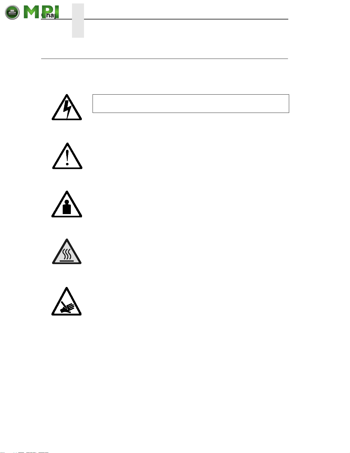
Safety And Notices
For your safety and to protect valuable equipment, read and comply with all
information highlighted under special headings:
This symbol indicates the presence of a hazard that could cause
death or serious injury.
DANGER
This symbol indicates the presence of a hazard that could cause
moderate or minor injury.
CAUTION
CAUTION
CAUTION
CAUTION
ATTENTION
IMPORTANT
This symbol indicates a heavy assembly that requires two or more
persons to lift or hold.
This symbol indicates a part or assembly that is hot enough to burn
you.
This symbol indicates a part or assembly that is sharp enough to cut
you.
Attention indicates the possibility of damage to a device, program,
system, or data.
Important indicates information vital to proper operation of the printer.
NOTE: A note gives you helpful information and tips about printer operation.
16
Page 17
Manual Conventions
Mantenimiento Periféricos Informáticos C/Canteras, 15 28860 Paracuellos de Jarama (Madrid) Tel: 00 34 917481604 Web: https://mpi.com.es/
• Operator panel keys are often shown by their symbol or icon (located on
the control panel directly below the key).
Example: Press the ↵ key for ENTER.
• LCD fault messages display the specific fault in uppercase letters.
A corrective action in upper and lowercase letters displays below the fault
message.
Example: PAPER OUT
• Key combinations are indicated by the + (plus) symbol.
Load Paper
Example: Press the Up key + Down key at the same time
Related Documents
•
Quick Setup Guide —
printer.
•
Maintenance Manual —
matrix printer at the field service level of maintenance.
•
IGP (PGL) Programmer's Reference Manual —
used with the optional IGP (PGL) Printronix emulation enhancement
feature.
•
ZGL™ Programmer’s Reference Manual
printer to function in the legacy ZPL
requiring modification to host data stream.
•
TGL™ Programmer’s Reference Manual
printer to function in the legacy TEC application environment without
requiring modification to host data stream.
•
IGL™ Programmer’s Reference Manual
printer to function in the legacy IPL application environment without
requiring modification to host data stream.
.
Explains how to unpack, install, and set up the
Explains how to maintain and repair the line
Provides information
— Provides information for the
application environment without
— Provides information for the
— Provides information for the
•
STGL™ Programmer’s Reference Manual
printer to function in the legacy SGL application environment without
requiring modification to host data stream.
•
DGL™ Programmer’s Reference Manual
printer to function in the legacy DGL application environment without
requiring modification to host data stream.
•
MGL™ Programmer’s Reference Manual
printer to function in the legacy MGL application environment without
requiring modification to host data stream.
•
IEGL® Programmer’s Reference Manual
printer to function in the legacy IER application environment without
requiring modification to host data stream.
— Provides information for the
— Provides information for the
— Provides information for the
— Provides information for the
17
Page 18

Chapter 1 Related Documents
Mantenimiento Periféricos Informáticos C/Canteras, 15 28860 Paracuellos de Jarama (Madrid) Tel: 00 34 917481604 Web: https://mpi.com.es/
•
Ethernet Interface Card User's Manual —
protocols, configuration, and operation.
•
Printer Management Utility User’s Manual
management utility which allows you to organize all of the printers in your
office remotely in a single database, download software and printer
settings from a host computer with a single mouse click.
•
RFID Label Reference Manual
6700-M40 printer and RFID label application.
Information about network
— Information about the printer
— Explains the use of the InfoPrint
18
Page 19
2 Operation
Mantenimiento Periféricos Informáticos C/Canteras, 15 28860 Paracuellos de Jarama (Madrid) Tel: 00 34 917481604 Web: https://mpi.com.es/
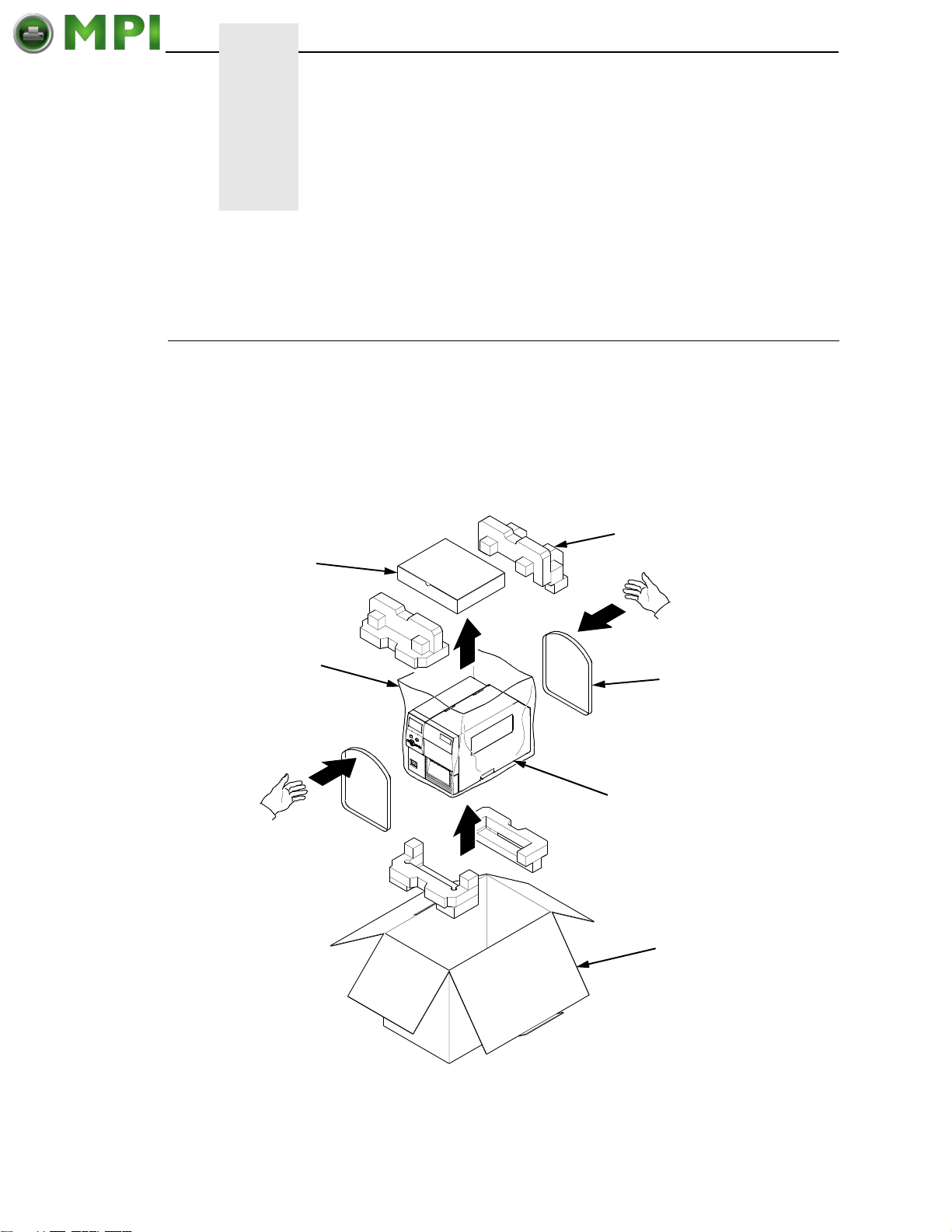
Unpacking The Printer
The printer is shipped in a carton and protective bag. The top lid of the carton
has instructions for removing the internal packing material. Keep all packing
material in case repacking is required.
ATTENTION
Accessories
Plastic Bag
Avoid touching the electrical connectors to prevent electrostatic
discharge damage while setting up the printer. The discharge of
accumulated electrostatic energy can damage or destroy the printhead
or electronic components used in this device.
Packing Material (4)
Lifting Strap (2)
Printer
Shipping Container
Figure 1. This Illustration Shows an Exploded View of Unpackaging the Printer
19
Page 20
Chapter 2 Installation
Mantenimiento Periféricos Informáticos C/Canteras, 15 28860 Paracuellos de Jarama (Madrid) Tel: 00 34 917481604 Web: https://mpi.com.es/
1. Place the shipping container upright on a flat, level surface.
2. Open the box and remove the first layer of packing material along with
any lose items.
3. Remove the accessories box and set it aside.
4. Pull the printer out of the shipping container by using the two plastic
straps as handles.
5. Remove the bands and plastic bag.
6. Check that all components on the packing list are included.
Installation
The following sections will guide you through the printer installation process.
1. Place the printer on a flat level surface that allows easy access to all sides
of the printer.
ATTENTION
CAUTION
IMPORTANT
Never operate the printer on its side or upside down.
2. Set the printer power switch to O (Off).
Failure to properly ground the printer may result in electric shock to
the operator.
In compliance with international safety standards, this printer has been
equipped with a three-pronged power cord. When inserted in a correctly
wired power outlet, the ground conductor will ensure that the printer
chassis is at ground (earth) potential. Do not use adapter plugs or
remove the grounding prong from the cable plug. If an extension cord is
required, ensure that a three-wire cable with a properly grounded plug is
used.
3. Attach the AC power cord to the AC power receptacle in the back of the
printer.
4. Attach the AC power cord to a grounded (three prong) electrical outlet of
the proper voltage. See
5. Attach Communication Interface:
“Power Cord Requirements” on page 22.
a. Parallel Interface
Attach a suitable parallel printer cable from the computer to the
Centronics/IEEE 1284 interface connector at the back of the printer.
Snap the bail locks to the Centronics connector to secure the
interface cable to the printer.
20
Page 21
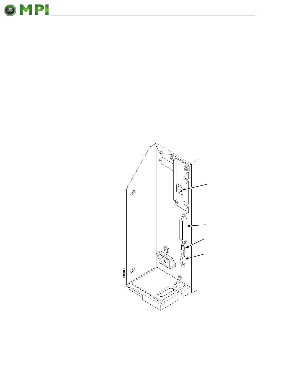
b. Serial Interface
Mantenimiento Periféricos Informáticos C/Canteras, 15 28860 Paracuellos de Jarama (Madrid) Tel: 00 34 917481604 Web: https://mpi.com.es/
Attach a suitable serial printer cable from the computer to the DB-9
RS-232 serial interface connector at the back of the printer.
For additional information on serial cable wiring, refer to “Routine
Care And Troubleshooting” on page 171.
c. USB
Attach a USB cable with noise suppresion filters on BOTH ends from
the computer to the USB connector at the back of the printer.
NOTE: The printer supports simultaneous connection of the parallel, serial,
and USB interfaces using the Auto Switching feature. Auto Switching
is described on
page 55.
d. Ethernet Connection
Insert a suitable ethernet cable from your hub or switch to the
ethernet connector located in the I/O panel in the rear of your printer.
Ethernet Interface
(optional)
Parallel Interface
USB Connection
Serial Interface
RS-232
Figure 2. This Illustration Shows the Interface Panel with Ethernet Option
21
Page 22
Chapter 2 Installation
Mantenimiento Periféricos Informáticos C/Canteras, 15 28860 Paracuellos de Jarama (Madrid) Tel: 00 34 917481604 Web: https://mpi.com.es/
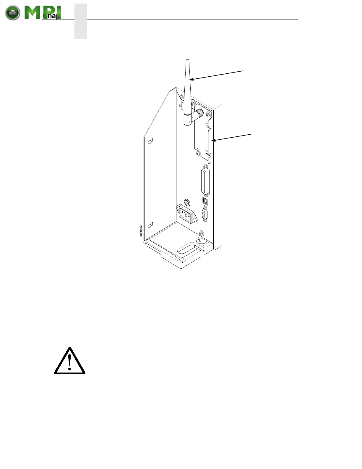
Wireless
Antenna
Wireless
Interface
CAUTION
IMPORTANT
22
Figure 3. This Illustration Shows the Wireless Interface Panel
Power Cord Requirements
In compliance with international safety standards, this printer is equipped with
a three-pronged electrical plug on the power cord. When this power cord is
plugged into a correctly wired power outlet, the ground conductor ensures that
the printer chassis is at ground (earth) electrical potential.
Failure to properly ground the printer can result in electrical shock to
the operator.
Never use adapter plugs without grounding prong. Never remove the
grounding prong from the power cable plug. If using an extension cord,
make sure it is a three-wire cable with a properly grounded plug.
Page 23

Setting Up The Printer
Mantenimiento Periféricos Informáticos C/Canteras, 15 28860 Paracuellos de Jarama (Madrid) Tel: 00 34 917481604 Web: https://mpi.com.es/
NOTE: This section describes the procedures for loading various types of
ribbon and media. You can also refer to instructions on the printer
itself, on a label on the inside of the media cover.
The term “media” in this manual refers to all the different kinds of paper, label,
or tag stock material that can be printed on by the printer. Your thermal printer
can print on continuous paper, adhesive backed labels, or non-adhesive tags
packaged in roll or fanfold form.
IMPORTANT
ATTENTION
ATTENTION
ATTENTION
IMPORTANT
For best results, use only genuine InfoPrint Solutions Company
supplies.
DO NOT TOUCH the printhead or the electronic components under the
pivoting deck. The discharge of electrostatic energy that accumulates
on the surface of the human body or other surfaces can damage or
destroy the printhead or electronic components used in this device.
Do not close the pivoting deck without label stock installed between the
printhead and the platen, because debris on the platen may damage the
printhead.
Avoid touching the electrical connectors while setting up the printer to
prevent electrostatic discharge damage. The discharge of accumulated
electrostatic energy can damage or destroy the printhead or electronic
components used in this printer.
Adhesive backed labels that DO NOT lay flat on the liner can jam the
printer. This can cause the label to peel off the liner. The exposed edges
can stick to the label guides and rollers inside the printer.
If you run out of labels while printing, do not turn off the printer while
reloading labels, because you can lose data.
See “Ordering Supplies And Accessories” on page 264.
23
Page 24
Chapter 2 Setting Up The Printer
Mantenimiento Periféricos Informáticos C/Canteras, 15 28860 Paracuellos de Jarama (Madrid) Tel: 00 34 917481604 Web: https://mpi.com.es/
Loading Ribbon
For direct thermal media (no ribbon required), go to page 27.
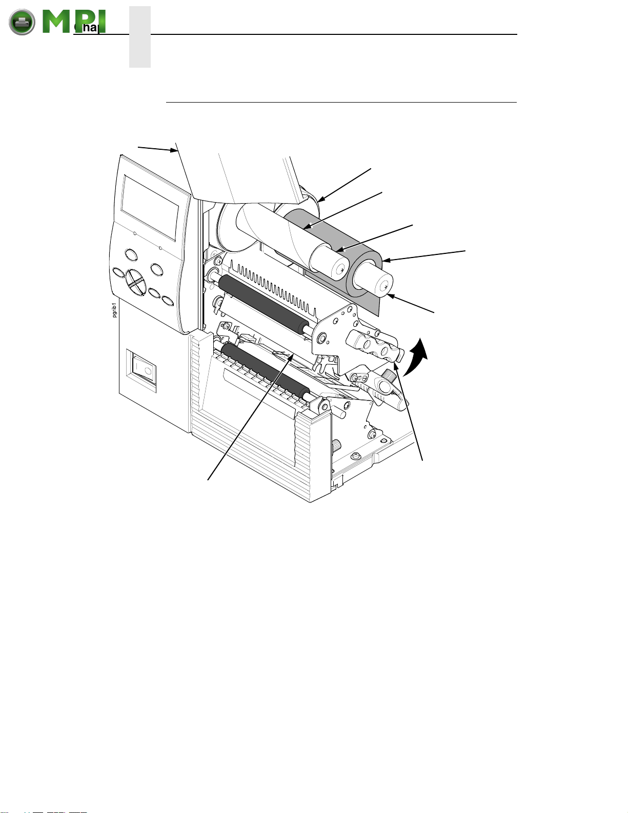
Media Cover
Flange
Ribbon
Take-Up Core
Ribbon
Take-Up Spindle
Ribbon
Roll
Ribbon
Supply Spindle
Deck Lock Lever
Pivoting
Deck
Figure 4. This Illustration Shows the Ribbon Roll on the Ribbon Supply Spindle and the
Ribbon Take-Up Core on the Ribbon Take-Up Spindle
IMPORTANT
Clean the printhead, platen roller, and media sensor every time you
change the ribbon. See
“Cleaning The Printhead, Platen Roller And
Media Sensors” on page 172.
1. Raise the media cover.
2. Install the ribbon take-up core on the ribbon take-up spindle.
NOTE: The first ribbon take-up core comes with the printer. Thereafter, move
the empty core from the ribbon supply spindle to the take-up spindle
after the ribbon is used up.
3. Slide the ribbon roll onto the ribbon supply spindle until it is flush with the
flange.
4. Open the pivoting deck and printhead by rotating the deck lock lever fully
counterclockwise until the deck and printhead swing upward.
24
Page 25
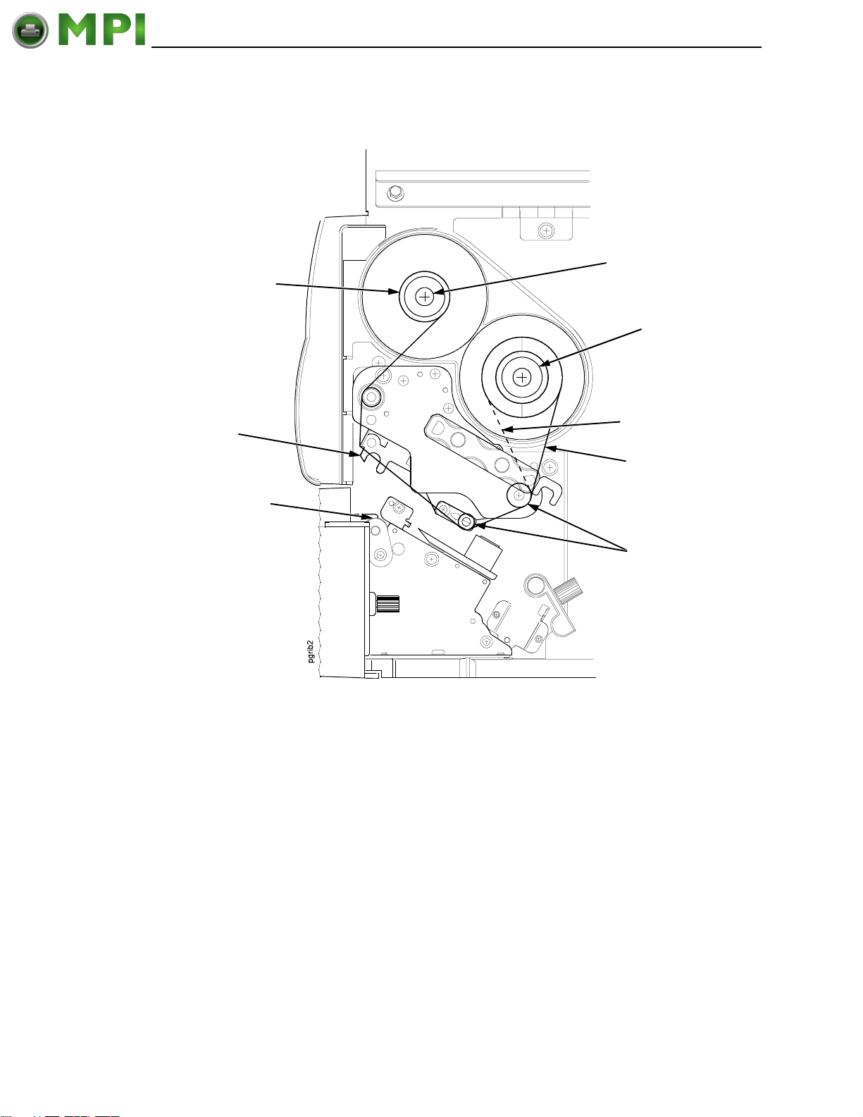
Ribbon Take-Up
Mantenimiento Periféricos Informáticos C/Canteras, 15 28860 Paracuellos de Jarama (Madrid) Tel: 00 34 917481604 Web: https://mpi.com.es/
Core
Printhead
Loading Ribbon
Ribbon
Take-Up Spindle
Ribbon
Supply Spindle
Alternate Ribbon
Path
Ribbon
Platen (not shown)
Ribbon Guide
Roller (2)
Figure 5. This Illustration Shows the Ribbon Routing Path From the Printer’s Side View
5. Thread the end of the ribbon under the ribbon guide rollers, between the
platen (rubber drive roller) and the printhead, and between the ribbon
take-up and supply spindles.
NOTE: Make sure to thread the ribbon behind the ribbon take-up spindle.
NOTE: The alternate ribbon path is for inside ink ribbon.
25
Page 26
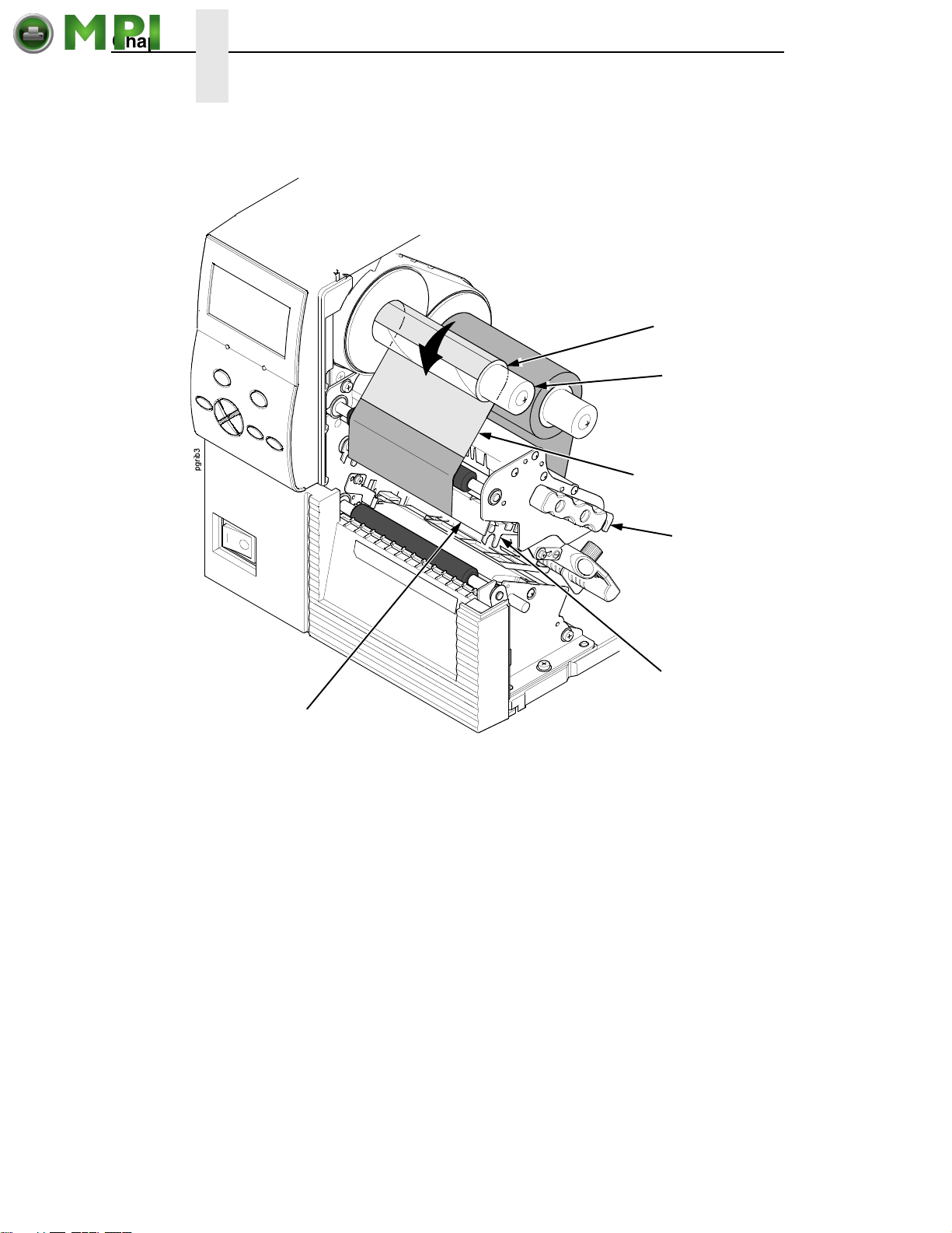
Chapter 2 Setting Up The Printer
Mantenimiento Periféricos Informáticos C/Canteras, 15 28860 Paracuellos de Jarama (Madrid) Tel: 00 34 917481604 Web: https://mpi.com.es/
Ribbon
Take-up Core
Ribbon
Take-up Spindle
Ribbon Leader
Deck Lock Lever
Printhead
Pivoting Deck
Figure 6. This Illustration Shows the Routed Ribbon Attached to the Ribbon Take-Up Core
IMPORTANT
Never attach the ribbon to the ribbon take-up spindle without a ribbon
take-up core installed.
6. Attach the ribbon to the ribbon take-up core on the ribbon take-up spindle
with tape.
7. Manually rotate the take-up spindle counterclockwise until the ribbon
leader has passed the printhead.
8. Rotate the deck lock lever fully clockwise to close the pivoting deck, and
attached printhead.
26
Page 27
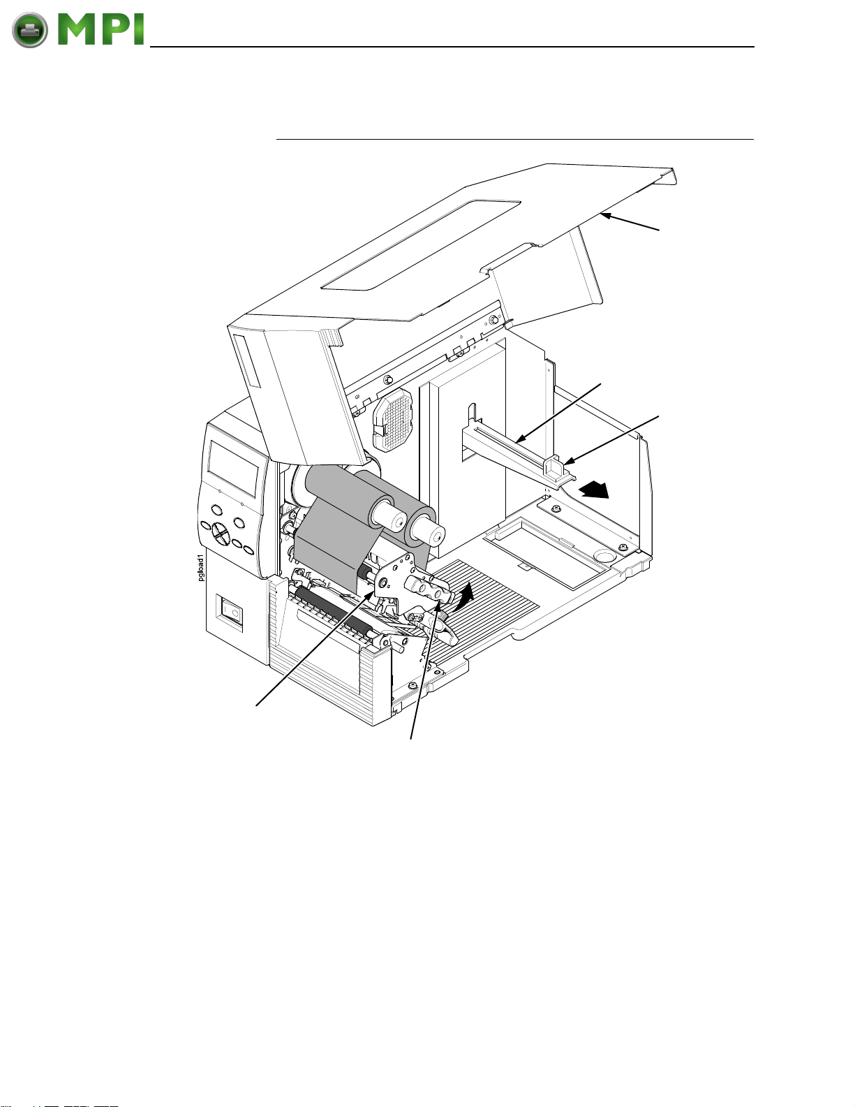
Loading Roll Media
Mantenimiento Periféricos Informáticos C/Canteras, 15 28860 Paracuellos de Jarama (Madrid) Tel: 00 34 917481604 Web: https://mpi.com.es/
Loading Roll Media
Media Cover
Media Hanger
Media Hanger
Guide
Pivoting Deck
Deck Lock Lever
Figure 7. This Illustration Shows the Pivoting Deck Open and the Media Hanger Guide Slid
Outward to the End of the Media Hanger
IMPORTANT
If you are using direct thermal mode, clean the printhead, platen roller,
and lower media sensor every time you change the media.
See “Cleaning The Printhead, Platen Roller And Media Sensors” on
page 172.
1. Slide the media hanger guide outward to the end of the media hanger
(as shown).
2. Remove and dispose of any empty media core.
3. Open the pivoting deck by rotating the deck lock lever fully
counterclockwise.
27
Page 28
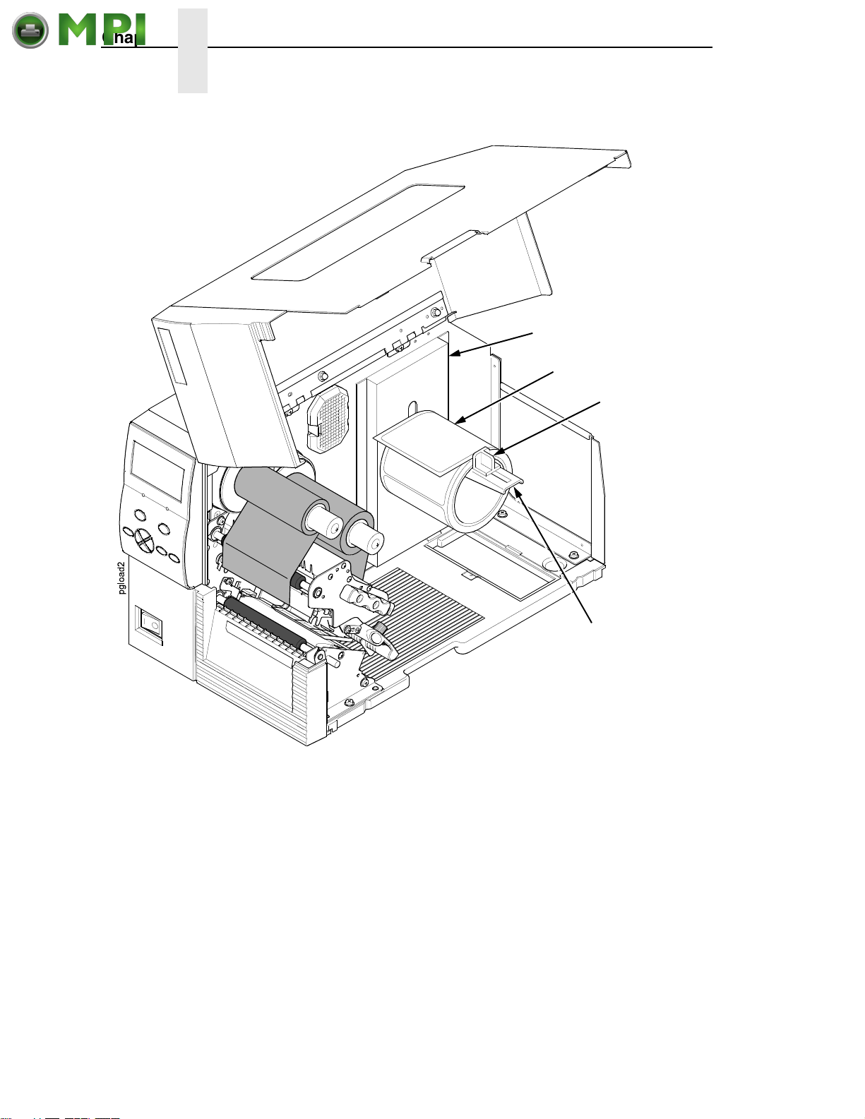
Chapter 2 Setting Up The Printer
Mantenimiento Periféricos Informáticos C/Canteras, 15 28860 Paracuellos de Jarama (Madrid) Tel: 00 34 917481604 Web: https://mpi.com.es/
Side Wall
Media Roll
Media Hanger
Guide
Media Hanger
Figure 8. This Illustration Shows the Media Roll Loaded Onto the Media Hanger
4. Place the media roll onto the media hanger and slide the media roll until it
is flush with the printer’s side wall.
NOTE: For information regarding smart labels, refer to the
Reference Manual
.
RFID Labeling
5. Slide the media hanger guide against the media roll to prevent horizontal
travel, but make sure the media roll can rotate freely.
28
Page 29
Printhead
Mantenimiento Periféricos Informáticos C/Canteras, 15 28860 Paracuellos de Jarama (Madrid) Tel: 00 34 917481604 Web: https://mpi.com.es/
Platen
(not shown)
Loading Roll Media
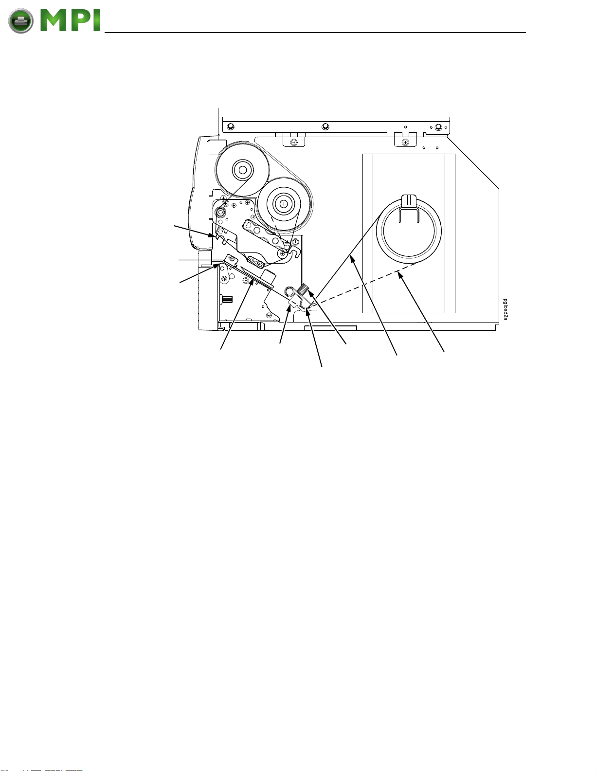
Media Sensor
Assembly
Media
Width Guide
Media Damper
Blue Locking
Knob
Media
Alternate
Media Path
Figure 9. This Illustration Shows the Media Routing Path From the Printer’s Side View
6. Thread the media under the media damper, through the media sensor
assembly, and then between the platen (rubber drive roller) and the
printhead.
NOTE: If you have the standard peel option, full media rewinder, or Standard
Peel with Liner Rewinder, see
“Using The Standard Peel Without
Liner Rewinder” on page 246, “Using The Full Media Rewinder
Option” on page 249, or “Using The Standard Peel With Liner
Rewinder Option” on page 258 for proper threading instructions.
NOTE: The alternate media path is for inside wound label media.
ATTENTION
If the blue media width guide locking knob is too loose or is removed,
the media width guide will fall off the printer.
7. Turn the blue media width guide locking knob counterclockwise just
enough to slide the media width guide, and no more.
8. Position the media width guide lightly against the outside edge of the
installed media and tighten the blue locking knob by turning it clockwise.
29
Page 30
Chapter 2 Setting Up The Printer
Mantenimiento Periféricos Informáticos C/Canteras, 15 28860 Paracuellos de Jarama (Madrid) Tel: 00 34 917481604 Web: https://mpi.com.es/
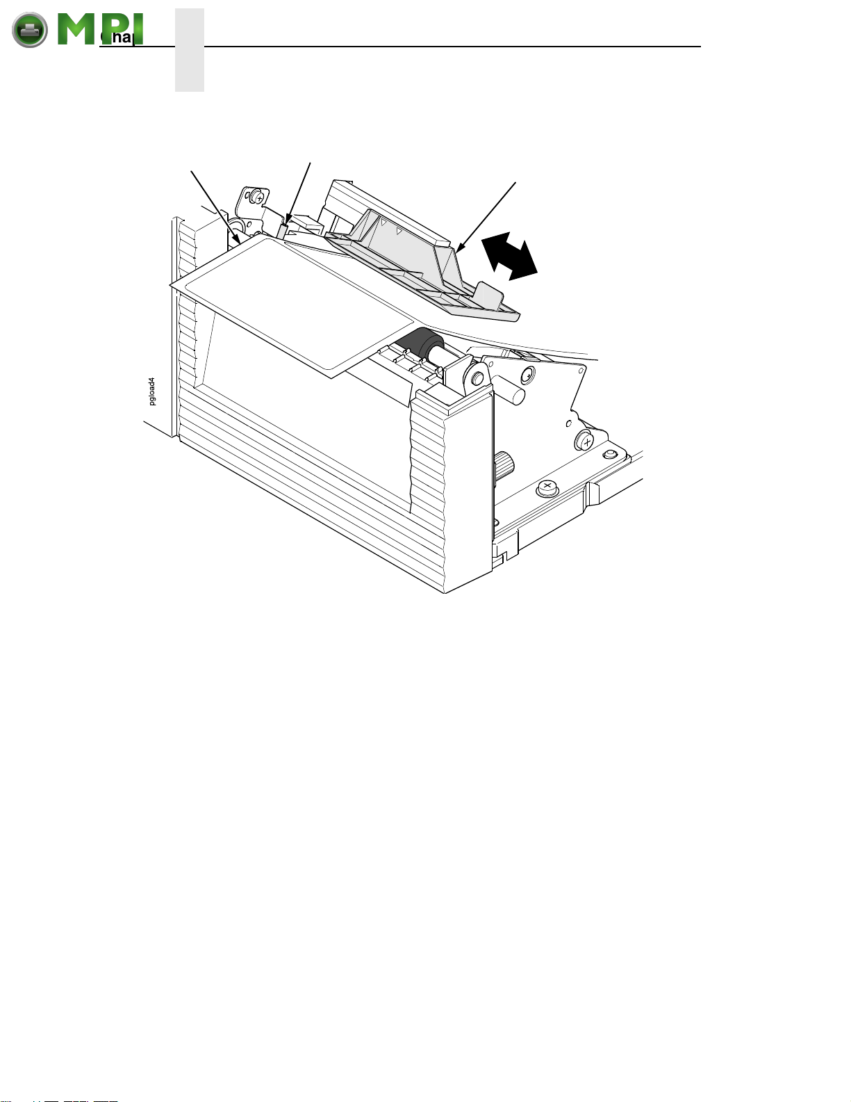
Media
(left edge)
Inside Media
Edge Guide
Media Sensor Assembly
Figure 10. This Illustration Shows the Media Sensor Assembly Adjusted Over the Media
9. Check the horizontal position of the media sensor assembly
(see “Positioning The Media Sensors” on page 47).
10. Align the left (inside) edge of the media with the inside media edge guide.
30
Page 31
Loading Roll Media
Mantenimiento Periféricos Informáticos C/Canteras, 15 28860 Paracuellos de Jarama (Madrid) Tel: 00 34 917481604 Web: https://mpi.com.es/
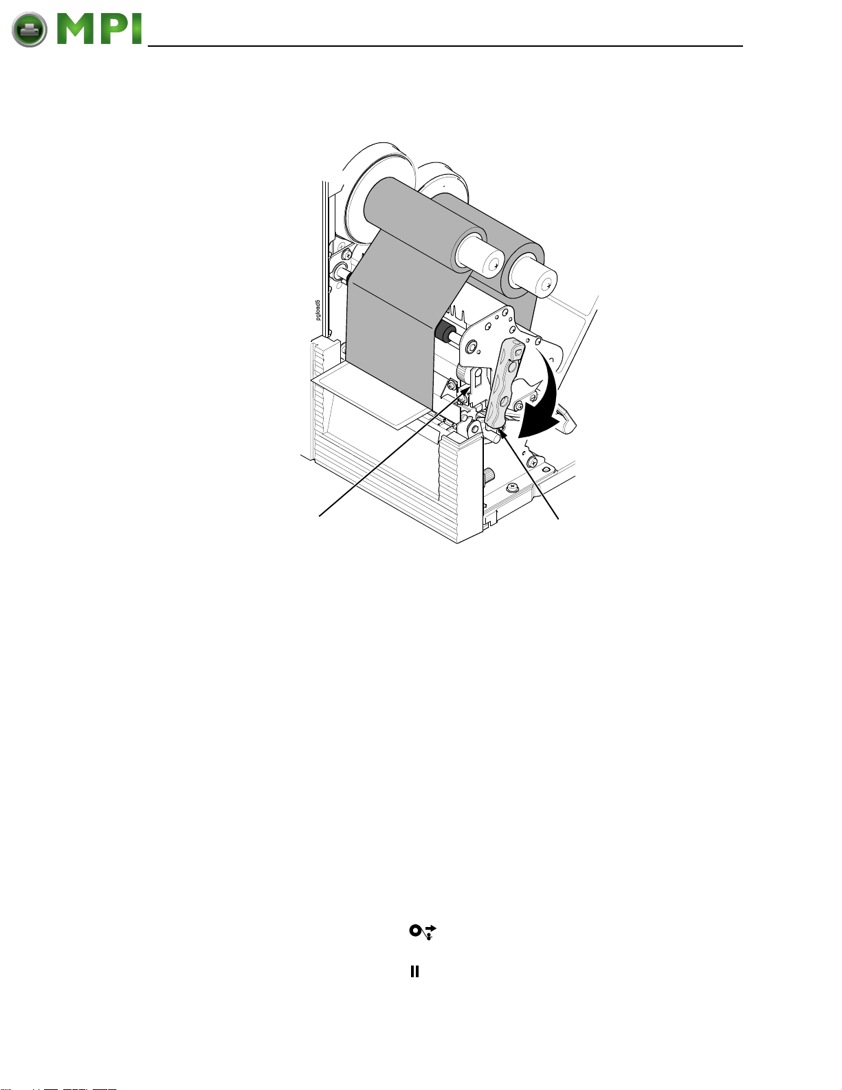
Pivoting Deck
Figure 11. This Illustration Shows the Ribbon and Media Loaded with the Pivoting Deck
Closed
11. Rotate the deck lock lever fully clockwise to close the pivoting deck.
This locks the pivoting deck and printhead into print position.
IMPORTANT
Ensure the printhead is down and locked before attempting to advance
media or print. Failure to do so will cause the “PRINT HEAD UP Close
Print Head” fault message to display.
12. Verify that Print Mode in the printer configuration menu is set for the
media type installed (Direct or Transfer). The Print Mode submenu is
located in the MEDIA SETUP menu. See
page 71 for details.
13. Verify the Gap/Mark Sensor selection matches the type of media
installed. See
“Sensing Different Media Types” on page 49.
Deck Lock Lever
“MEDIA SETUP Menu” on
• If you have not run an Auto Calibrate, do so now. See “Running Auto
Calibrate” on page 50.
• If you have already run an Auto Calibrate, complete the following
steps:
a. Close the media cover.
b. Press the (Feed) key once to verify that the media
advances.
c. Press the (Pause) key to place the printer online.
31
Page 32
Chapter 2 Setting Up The Printer
Mantenimiento Periféricos Informáticos C/Canteras, 15 28860 Paracuellos de Jarama (Madrid) Tel: 00 34 917481604 Web: https://mpi.com.es/
Loading Fanfold Media
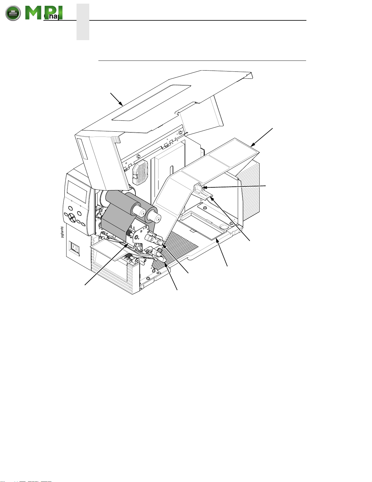
Media Cover
Fanfold
Media
Media
Hanger Guide
Bottom Panel
Opening
Pivoting Deck
Deck Lock
Lever
Media Damper
Figure 12. This Illustration Shows the Loading of Fanfold Media
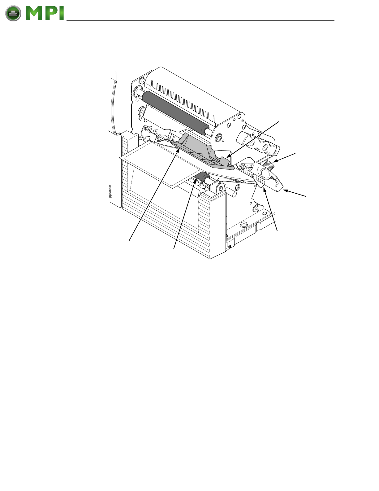
1. Open the media cover.
2. Slide the media hanger guide outward to the end of the media hanger.
3. Place the fanfold media either behind or beneath the printer, depending
on the desired fanfold supply location. Insert the first few labels through
either the rear or bottom panel opening.
4. Place the media over the media hanger, flush against the back of the
printer.
5. Slide the media hanger guide against the outer edge of the fanfold media
to prevent horizontal travel.
6. Open the pivoting deck by rotating the deck lock lever fully
counterclockwise until the deck and printhead swing upward.
Media Hanger
32
Page 33
Loading Fanfold Media
Mantenimiento Periféricos Informáticos C/Canteras, 15 28860 Paracuellos de Jarama (Madrid) Tel: 00 34 917481604 Web: https://mpi.com.es/
Media Sensor
Handle
Locking Knob
Media
Damper
Media Width
Media Sensor
Assembly
Platen
Guide
Figure 13. This Illustration Shows How to Secure Media Under the Media Damper Using the
Locking Knob and the Media Width Guide
7. Thread the media under the media damper, through the media sensor
assembly, and then between the platen (rubber drive roller) and the
printhead. You can also refer to the label inside the media cover for media
loading instructions.
ATTENTION
If the media width guide locking knob is too loose or is removed, the
media width guide will fall off the printer.
8. Turn the media width guide locking knob counterclockwise just enough to
slide the media width guide, and no more.
9. Position the metal guide lightly against the outside edge of the installed
media and tighten the locking knob by turning it clockwise.
10. Check the horizontal position of the media sensor assembly
(see “Positioning The Media Sensors” on page 47).
33
Page 34
Chapter 2 Setting Up The Printer
Mantenimiento Periféricos Informáticos C/Canteras, 15 28860 Paracuellos de Jarama (Madrid) Tel: 00 34 917481604 Web: https://mpi.com.es/
Inside Media
Media
(left edge)
Edge Guide
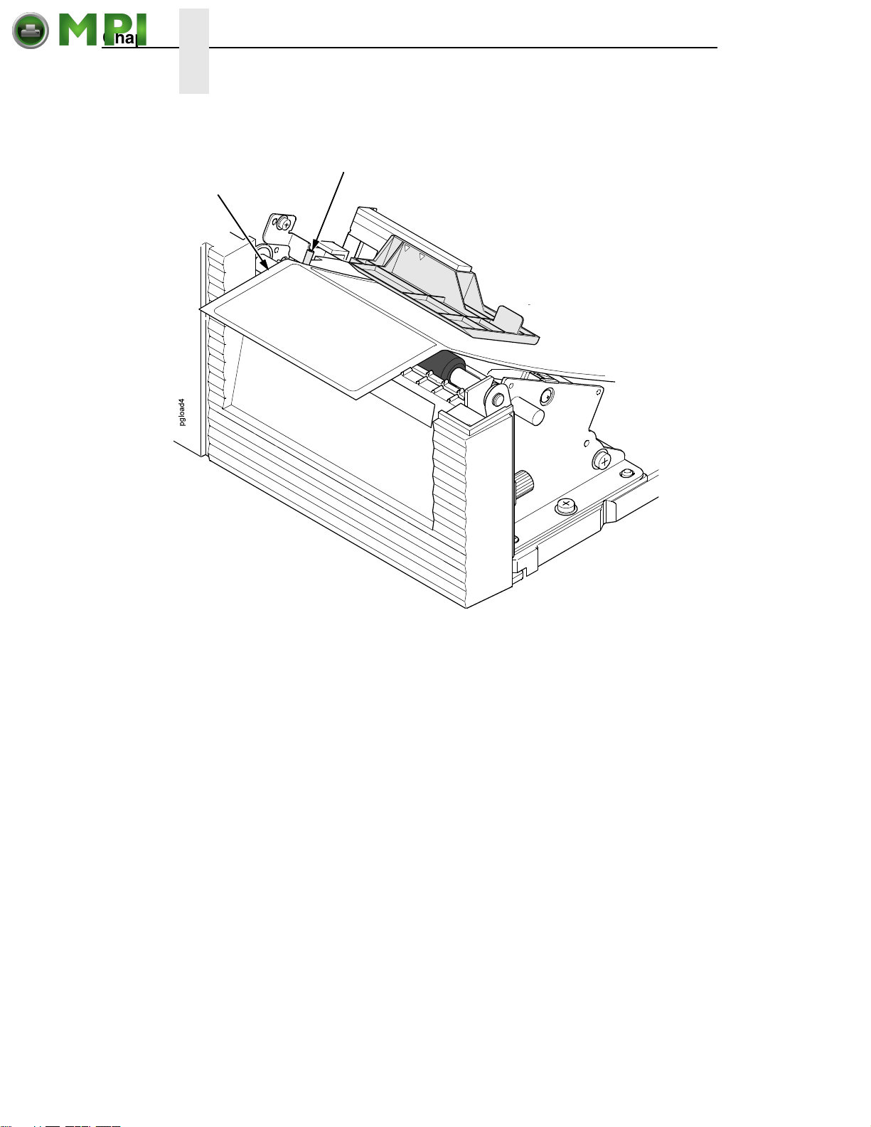
Figure 14. This Illustration Shows Media Alignment Along the Inside Media Edge Guide
11. Align the left (inside) edge of the media with the inside media edge guide.
34
Page 35
Loading Fanfold Media
Mantenimiento Periféricos Informáticos C/Canteras, 15 28860 Paracuellos de Jarama (Madrid) Tel: 00 34 917481604 Web: https://mpi.com.es/
Pivoting Deck
Deck Lock
Lever
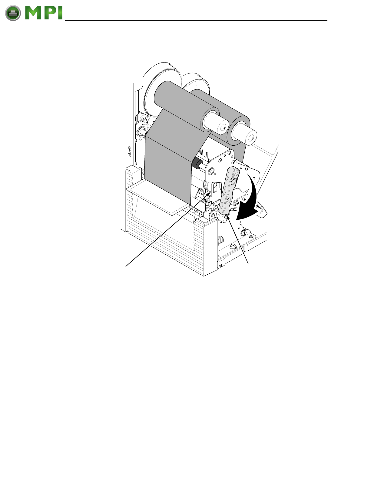
Figure 15. This Illustration Shows the Ribbon and Media Loaded with the Pivoting Deck
Closed
12. Close the pivoting deck by rotating the deck lock lever fully clockwise.
IMPORTANT
Ensure the pivoting deck is down and locked before attempting to
advance media or print. Failure to do so will cause the “PRINT HEAD UP
Close Print Head” fault message to display.
13. Verify that Print Mode submenu is set for the media type installed (direct
or transfer). The Print Mode submenu is located in the MEDIA SETUP
menu. See
“Main Menu” on page 69 for more information. Also, if thermal
transfer media is installed, see “Loading Ribbon” on page 24.
14. Verify the Gap/Mark Sensor selection matches the type of media
installed. See
“Sensing Different Media Types” on page 49.
35
Page 36
Chapter 2 Operating Modes
Mantenimiento Periféricos Informáticos C/Canteras, 15 28860 Paracuellos de Jarama (Madrid) Tel: 00 34 917481604 Web: https://mpi.com.es/
For direct thermal operation (no ribbon required) or thermal transfer
operation (ribbon required):
• If you have not run an Auto Calibrate, do so now. See “Running Auto
Calibrate” on page 50.
• If you have already run an Auto Calibrate, complete the following
steps:
a. Close the media cover.
b. Press the (Feed) key once to verify that the media
advances.
c. Press the (Pause) key to place the printer online.
NOTE: When changing to Online mode, if the operator has changed menu
items, but not saved the changes in a configuration, the operator will
be prompted to save the changes.
Operating Modes
The current operating mode can be selected through the control panel keys or
can result from routine operations such as powering on the printer.
Online: In online mode, the printer can receive and print data sent from the
host. Pressing the Pause key toggles the printer between the online and
offline modes. The ONLINE status indicator is lit green in online mode.
Offline: In offline mode, you can perform operator functions such as loading
media or changing ribbon. Pressing the Pause key toggles the printer from
offline to online mode. The ONLINE status indicator is not illuminated in offline
mode.
Menu: Pressing the MENU key takes the printer offline and into Menu mode.
In this mode, you can navigate through all configuration and status menus
and change the printer configuration.
Fault: In fault mode, a fault condition exists that must be cleared before
printing can continue. The FAULT status indicator flashes red, the alarm
beeps (if configured to do so), and a descriptive fault message displays. The
ONLINE status indicator turns off.
The fault must be corrected first and then the message cleared by pressing
the Pause key before normal printing can continue.
36
Page 37

Controls And Indicators
Mantenimiento Periféricos Informáticos C/Canteras, 15 28860 Paracuellos de Jarama (Madrid) Tel: 00 34 917481604 Web: https://mpi.com.es/
Power Switch
The power switch is located on the bottom front panel of the printer. To apply
power, place the switch in the | (On) position. When you first power on the
printer, a series of initialization messages will appear on the LCD (Liquid
Crystal Display) on the control panel.
To remove power, place the power switch in the O (Off) position.
Powering On The Printer
When you power on the printer, it executes a self-test. During the self-test, the
LCD momentarily displays the DPI resolution (203 or 305 DPI) of the installed
printhead. The default power-on state is online. Once the printer has
successfully initialized, the ONLINE status indicator light illuminates, and the
active LCD indicates ONLINE, the printer model (6700-M40), the printhead
installed (203 or 305 dpi), the communication interface, and the emulation
selected.
Power Switch
If there is a fault during the self-test, the FAULT (!) status indicator flashes,
and a fault message appears on the display. The alarm may also sound, if
configured to do so.
37
Page 38
Chapter 2 Controls And Indicators
Mantenimiento Periféricos Informáticos C/Canteras, 15 28860 Paracuellos de Jarama (Madrid) Tel: 00 34 917481604 Web: https://mpi.com.es/
Control Panel
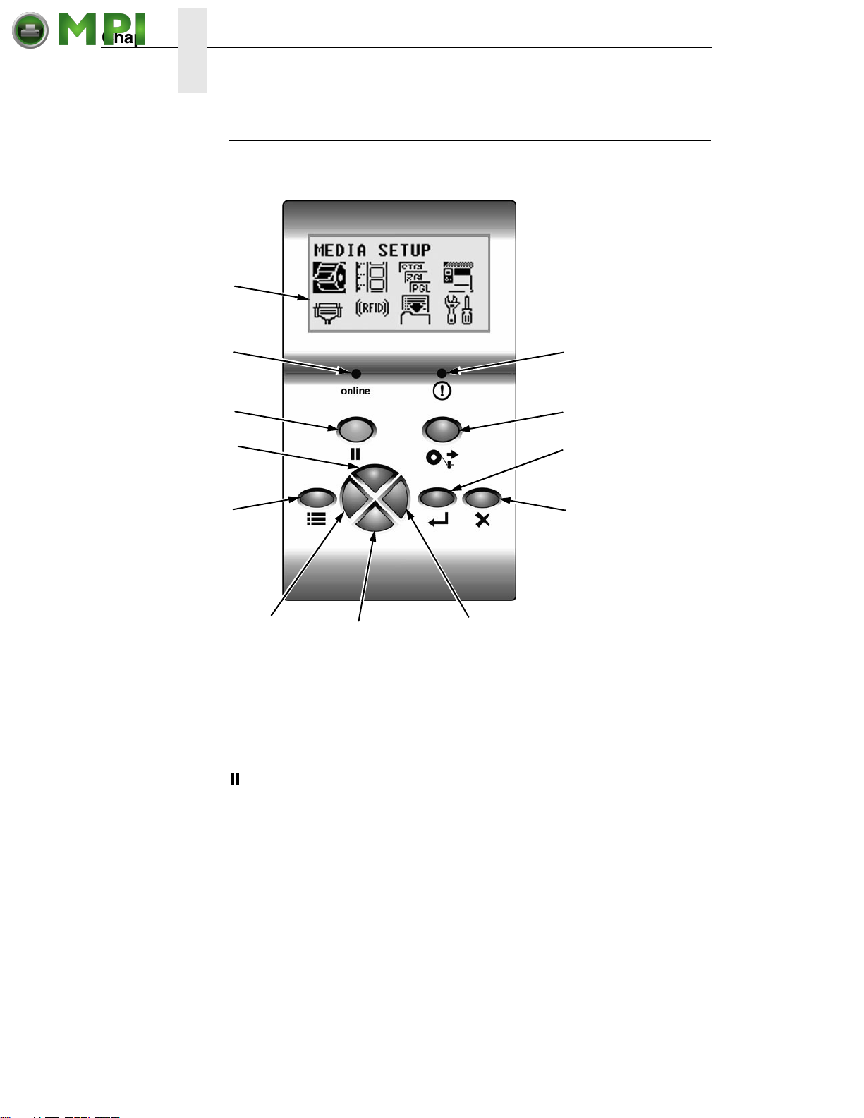
The control panel is located on the front of the printer and includes an LCD,
indicators, and control keys (buttons).
LCD (Liquid
Crystal Display)
Online Indicator
Pause Key
Up Key
Menu Key
Fault Indicator
Feed Key
Enter Key
Cancel Key
NOTE: Press the Down
and
↵ (Enter) keys at the
same time to lock or
unlock the
Left Key
Figure 16. This Illustration Shows the Control Panel
Down Key
Right Key
↵ key.
Liquid Crystal Display (LCD)
A backlighted LCD that will display up to four rows of 16 characters each or
eight rows of 21 characters each.
Pause Key
The Pause key toggles the printer between Online and Offline Modes.
The key performs the following in Online, Offline, Fault, and Menu modes:
• Online Mode – sets the printer to Offline Mode.
• Offline Mode – sets the printer to Online Mode.
• Fault Mode – causes the printer to recheck the faults; if the faults have
been cleared, the printer toggles to the Offline mode.
• Menu Mode – sets the printer to Menu Mode.
NOTE: When changing to Online mode, if the operator has changed menu
items, but not saved the changes in a configuration, the operator will
be prompted to save the changes.
38
Page 39
Control Panel
Mantenimiento Periféricos Informáticos C/Canteras, 15 28860 Paracuellos de Jarama (Madrid) Tel: 00 34 917481604 Web: https://mpi.com.es/
Feed Key
The Feed Key advances the media one label length in Online and Offline
Mode. If there is data in the printer, the printer will print the data before
ejecting the label. This key is inactive in all other modes.
Menu Key
In Online, Offline, or Fault modes, the Menu key causes the printer to enter
the Menu mode and the top level menu icons to display. In Menu mode, the
Menu key will move to the first Icon position in the top level Icon menu. This
key is inactive in all other modes.
Cancel Key
If enabled, the Cancel key clears all data in the printer data buffer in Offline
mode. In Menu mode, this key moves up to the previous higher level menu.
↵ Enter Key
• In Menu mode (at the icon menu level): pressing the Enter key will move
down into the menu tree for the highlighted icon.
• Within a menu tree: if the highlighted menu contains submenus instead of
a selectable parameter, pressing the Enter key will move down into the
submenus of that menu. If the highlighted menu is a display only menu
then pressing the Enter key performs no function. If the highlighted menu
has selectable parameters, pressing the unlocked Enter key will select
the displayed parameter. An asterisk (*) displays next to the selected
parameter.
If the highlighted menu is an executable menu, pressing the unlocked
Enter key will cause the function associated with the executable menu to
run. If the Enter key is locked, pressing the Enter key for highlighted
menus that are executable or contain selectable parameters will cause a
momentary display of THE
NOTE: Press the Down and ↵ key at the same time to lock/unlock the ↵ key.
For special Network Address menus or String menus, pressing the Enter
key will move down into a special multiple segment setting menu. Exit this
menu by pressing Enter again to save the changes or Cancel to exit
without saving the changes. This key is inactive in all other modes.
↵ KEY IS LOCKED message.
39
Page 40

Chapter 2 Controls And Indicators
Mantenimiento Periféricos Informáticos C/Canteras, 15 28860 Paracuellos de Jarama (Madrid) Tel: 00 34 917481604 Web: https://mpi.com.es/
Up Key
In Menu mode (at the icon menu level), this key will move to the next row of
icons. If on the bottom row it will move up the top row of icons. If at the top of
the menu tree, pressing the Up key will go to the bottom of the menu tree.
Within each menu, this key will scroll to the previous submenu in the menu
tree.
If in special multiple segment setting menus for Network Address menus or
string menus, pressing the Up key will increment the segment or character
value. If at the top of the segment or character value range, pressing the Up
key will go to the bottom of that value range.
In Offline mode, the Up key takes you to the Load Config. menu.
See “Loading A Saved Configuration” Method 1 on page 154.
This key is inactive in all other states. This key is typematic and if held down
will start to accelerate.
Down Key
In Menu mode (at the icon menu level), this key will move to the next row of
icons. If on the top row it will move to the bottom row of icons. If at the bottom
of the menu tree, pressing the Down key will go to the top of the menu tree.
Within each menu, this key will scroll to the next submenu in the menu tree.
If in special multiple segment setting menus for Network Address menus or
String menus, pressing the Down key will decrement the segment or
character value. If at the bottom of the segment or character value range,
pressing the Down key will go to the top of that value range.
This key is inactive in all other states. This key is typematic and if held down
will start to accelerate.
Right Key
In Offline mode, this key adjusts the display brightness of the LCD. In Menu
mode (at the icon menu level), this key will advance from one menu icon to
the next menu icon. If at the end of one row of icons it will move to the
beginning of the other row of icons.
Within a menu tree, if the highlighted menu has a selectable parameter,
pressing the Right key causes the parameter to increment or display the next
parameter on the list. If at the top of the parameter range, pressing the Right
key will move to the bottom of the parameter range.
If in special multiple segment setting menus for Network Address menus or
String menus, pressing the Right key will move to the next segment or
character without losing changes made to the current segment or character.
If at the end of the segments or characters, pressing the Right key will go to
the beginning of the segments or characters. None of the changes to the
segments or characters will take affect until the Enter Key is pressed.
This key is inactive in all other states. This key is typematic and if held down
will start to accelerate.
40
Page 41

Control Panel
Mantenimiento Periféricos Informáticos C/Canteras, 15 28860 Paracuellos de Jarama (Madrid) Tel: 00 34 917481604 Web: https://mpi.com.es/
Left Key
In Offline mode, this key adjusts the display brightness of the LCD. In Menu
mode (at the icon menu level), this key will advance from one menu icon to
the previous menu icon. If at the beginning of one row of icons it will move to
the end of the other row of icons.
Within a menu tree, if the highlighted menu has a selectable parameter,
pressing the Left key causes the parameter to decrement or display the
previous parameter on the list. If at the bottom of the parameter range,
pressing the Left key will move to the top of the parameter range.
If in special multiple segment setting menus for Network Address menus or
String menus, pressing the Left key will move to the previous segment or
character without losing changes made to the current segment or character.
If at the begining of the segments or characters, pressing the Left key will go
to the end of the segments or characters. None of the changes to the
segments or characters will take affect until the Enter Key is pressed.
This key is inactive in all other states. This key is typematic and if held down
will start to accelerate.
Combination Keys
• Menu Unlock Combo Key
A combination key whose default setting is the Enter and Down keys
pressed simultaneously. In Menu mode, this key toggles locking and
unlocking of the Enter key. This key is inactive in all other modes. When
the Enter key is locked it prevents the operator from modifying the menu
settings. The default is the Enter and Down keys.
NOTE: To change the default menu lock/unlock combo keys to a different
key or combination, select PRINTER SETUP
Admin User must be enabled for the Set Lock Key option to display.
Set Lock Key.
• Soft Reset Combo Key
A combination key that causes the printer to perform a soft reset by
pressing the Left and Right keys simultaneously in Offline and Menu
modes. This combo key is inactive in all other modes.
• Download Combo Key
A combination key that places the printer in download mode.
Online Indicator
Indicates when the printer is online or offline. The online indicator stays lit
when the printer is online, ready to print and blinks while accepting data from
the host.
(!) Fault Indicator
Flashes during a fault condition.
41
Page 42

Chapter 2 Media Handling Modes
Mantenimiento Periféricos Informáticos C/Canteras, 15 28860 Paracuellos de Jarama (Madrid) Tel: 00 34 917481604 Web: https://mpi.com.es/
Media Handling Modes
Before you load media, you must decide which media handling mode to use:
• Tear-Off Strip (factory default). Printer prints on the media and sends it
out the front until the print buffer is empty, then positions the last label
over the tear bar for removal.
• Continuous. Prints on the media and sends it out the front of the printer.
• Peel-Off. Prints and peels die-cut labels from the liner without assistance.
The printer waits for you to take away the label before printing the next
one (on-demand printing). Supported only when Standard Peel or
Standard Peel with Liner Rewinder option is installed. When either option
is installed with liner attached, a “Remove Label” message will display to
remind you to remove the label before the next one can be printed.
NOTE: This mode is only supported when the Standard Peel without Liner
Rewinder option or Standard Peel with Liner Rewinder option is
installed.
NOTE: If the Peel-Off option is not installed, the error message “OPTION
NOT INSTALLED” displays. Requires the Standard Peel with or
without Liner Rewinder options to be installed.
• Cut. When the optional media cutter is installed, it automatically cuts
media after each label is printed or after a specified number of labels
have been printed when a software cut command has been issued. It cuts
continuous roll paper, labels, or tag stock.
NOTE: The Cut option is not allowed if the cutter is not installed. The error
message “OPTION NOT INSTALLED” displays.
• Rewind. In rewind mode the printer unwinds the media from the media
supply roll or fanfold label stack, prints the labels, and rewinds the printed
media and its carrier web onto the optional rewind spindle. For the
optional Rewinder, use “Rewind” for Batch Rewind mode (see
Full Media Rewinder Option” on page 249).
NOTE: “OPTION NOT INSTALLED” displays if the Full Media Rewinder
option is not installed.
Once you have decided on the mode, configure the printer. See Chapter 4 for
more information.
“Using The
42
Page 43
Printhead Pressure Adjustment
Mantenimiento Periféricos Informáticos C/Canteras, 15 28860 Paracuellos de Jarama (Madrid) Tel: 00 34 917481604 Web: https://mpi.com.es/
Media Thickness Adjustment
Printhead
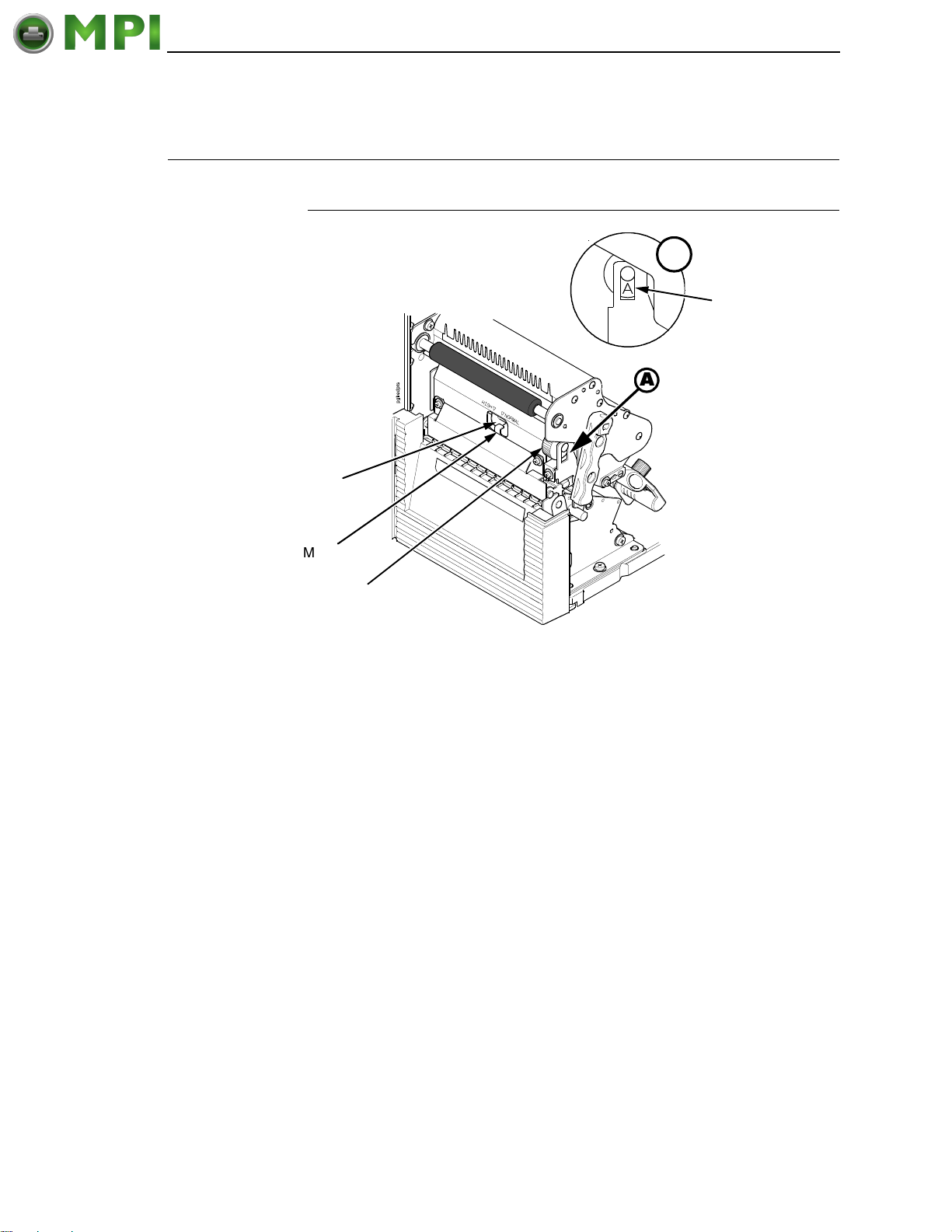
Pressure Switch
(blue)
Media Thickness Adjustment
A
Indicator
Window
A
Metal Tab
Printhead Balance
Adjustment Dial
Figure 17. This Illustration Shows the Printhead Pressure Switch, Printhead Balance
Adjustment Dial, and the Indicator Window
This procedure adjusts the printhead pressure to accomodate media of
different thicknesses. This will minimize printhead wear and optimize print
quality. The printhead pressure switch has two positions, high and normal.
Follow this procedure to adjust the media thickness:
1. Rotate the printhead balance adjustment dial until “A” appears in the
indicator window (see Detail A above).
NOTE: The dial must be set to “A”. If you have the dial set to a numerical
value, you cannot slide the printhead pressure switch.
43
Page 44
Chapter 2 Printhead Pressure Adjustment
Mantenimiento Periféricos Informáticos C/Canteras, 15 28860 Paracuellos de Jarama (Madrid) Tel: 00 34 917481604 Web: https://mpi.com.es/
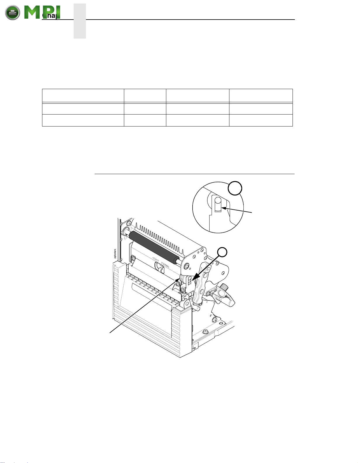
2. Slide the printhead pressure switch to NORMAL or HIGH depending on
the media thickness (see
pressure switch completely to either side of the metal tab.
Table 2. Media Thickness Adjustment
Media Setting Inches Millimeters
Thin paper, normal label, etc. NORMAL 0.003 to 0.008 0.076 to 0.200
Thick paper, tag stock, etc. HIGH 0.008 to 0.010 0.200 to 0.254
3. Adjust the media width by rotating the printhead balance adjustment dial
to the appropriate setting (see
position.
Table 2). Make sure to slide the blue printhead
page 45). Do not leave the dial in the “A”
Media Width Adjustment
Printhead Balance
Adjustment Dial
B
3
B
Indicator
Window
Figure 18. This Illustration Shows the Printhead Balance Adjustment Dial and the Indicator
Window
Media width adjustment allows you to vary printhead pressure along the
platen from one end to the other. If the printhead pressure is out of balance,
the printed image will be darker on one side of the label than the other and the
media will travel in the direction with the least resistance.
44
Page 45
Printhead
Mantenimiento Periféricos Informáticos C/Canteras, 15 28860 Paracuellos de Jarama (Madrid) Tel: 00 34 917481604 Web: https://mpi.com.es/
Balance Dial
Setting
Media Width Adjustment
The printhead balance adjustment dial is scaled in numerals to help you
balance adjustment based on the width of the media. The balance shown in
the indicator window is the active setting.
1. Determine the correct value based on the media width (see Table 3).
Table 3. Printhead Balance Adjustment Ranges
A 1 to 2 2 to 4 4 to 5
Paper Width N/A (Used to adjust
the printhead
pressure switch only.
See
page 43)
2. Rotate the printhead balance adjustment dial until the correct value
appears in the indicator window (see Detail B above).
1.00 to 2.16 inches
(25mm to 55mm)
2.16 to 3.15 inches
(55mm to 80mm)
3.15 to 5.15 inches
(80mm to 131mm)
45
Page 46
Chapter 2 Printhead Pressure Adjustment
Mantenimiento Periféricos Informáticos C/Canteras, 15 28860 Paracuellos de Jarama (Madrid) Tel: 00 34 917481604 Web: https://mpi.com.es/
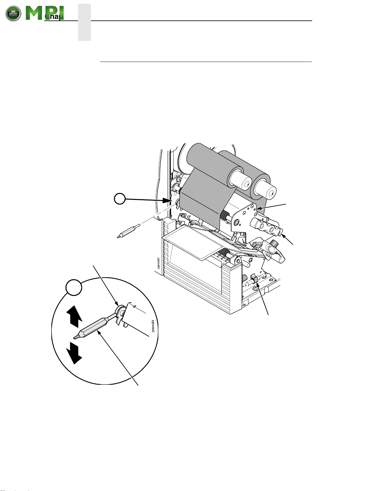
Printhead Alignment
Align the printhead under the following conditions: to improve the print quality
when running difficult media with major differences in thickness, when
adjusting for media thickness (with the printhead pressure switch) did not
yield adequate print quality, or when you replace the printhead.
The printhead must be parallel with the platen for consistent image printing
across the label. If the printhead is misaligned, labels will print with uneven ink
distribution (i.e. splotches and fading ink). When you align the printhead, you
are moving the printhead forward and backward in relation to the platen.
Printhead
Alignment Dial
A
A
Pivoting
Deck
Deck Lock
Lever
Tool Clip
Printhead
Alignment Tool
Figure 19. This Illustration Shows How to Use the Printhead Alignment Tool to Adjust the
Printhead Alignment Dial
46
Page 47
1. Raise the media cover.
Mantenimiento Periféricos Informáticos C/Canteras, 15 28860 Paracuellos de Jarama (Madrid) Tel: 00 34 917481604 Web: https://mpi.com.es/
2. Open the pivoting deck by rotating the deck lock lever fully
counterclockwise.
3. Remove the printhead alignment tool (yellow screwdriver) from the tool
clip.
4. Use the printhead alignment tool to turn the printhead alignment dial.
Turn the printhead alignment dial UP for THICKER stocks and DOWN for
THINNER stocks.
5. Close the pivoting deck by rotating the deck lock lever fully clockwise.
6. Run a print test, such as the checkerboard or gray scale.
See “Printer Tests” on page 145.
7. If necessary repeat steps 4 to 6 until the desired alignment is achieved.
8. Lower the media cover.
Positioning The Media Sensors
Printhead Alignment
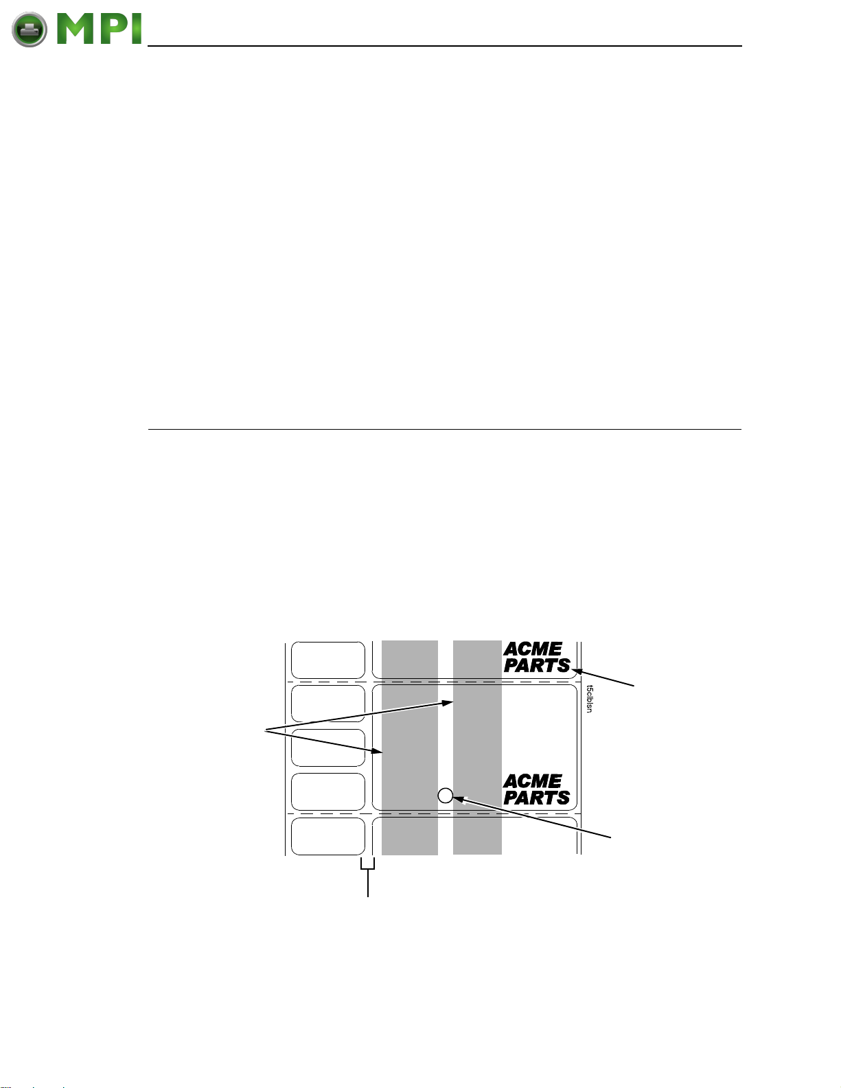
Position the media
sensors in either of
the grey shaded
areas.
Your printer is equipped with a media sensor assembly that detects the
top-of-form position on media with label length indicators (gaps, notches,
holes, or black marks). These sensors also detect when a Paper Out
condition exists.
See page 215 for media and label length indicators.
The media sensors should not be placed in the path of media features that
could cause false gap detection or paper out faults. Such features are dark
pre-printing, rounded die-cut label corners, vertical gaps associated with
side-by-side labels, and extraneous cut-outs, as shown below.
Dark Pre-printing
Extraneous Cut-out
Vertical Gap and
Rounded Die-cut
Label Corners
Figure 20. This Illustration Shows A Label with Dark Pre-Printing, Cut-Outs, Vertical Gaps,
and Rounded Die-Cut Label Corners
47
Page 48
Chapter 2 Positioning The Media Sensors
Mantenimiento Periféricos Informáticos C/Canteras, 15 28860 Paracuellos de Jarama (Madrid) Tel: 00 34 917481604 Web: https://mpi.com.es/
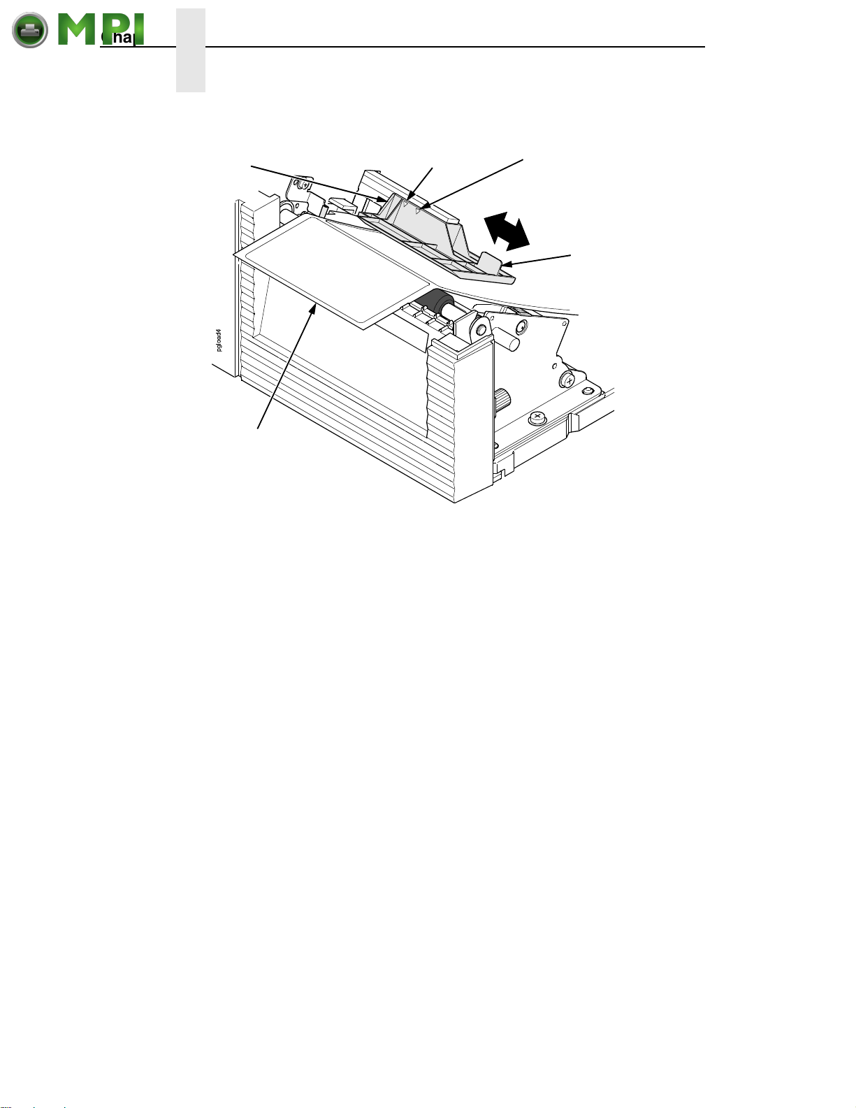
Media Sensor
Assembly
Media
Figure 21. This Illustration Shows How to Use the Media Sensor Handle to Slide the Media
Mark Sensor Indicator
(both sides)
Sensor Assembly
Gap Sensor Indicator
(both sides)
Media Sensor
Handle
Sensing Media with Horizontal Black Marks or Inboard
Notches
1. Use the media sensor handle to horizontally position the media sensor
assembly so that the sensor indicators (embossed on both sides) are
aligned with the reference marks on the media.
2. Select Mark in the Gap/Mark Sensor submenu under the SENSOR
SETUP menu. See
NOTE: If using media with shallow notches, i.e. notches that are cut short
where the media sensor cannot be adjusted to detect the notch, be
sure to select Mark in the Gap/Mark Sensor submenu under
SENSOR SETUP menu. For Mark sensing, the ribbon must be
loaded, see
3. Perform an Auto Calibrate. See “Running Auto Calibrate” on page 50.
“Sensing Different Media Types” on page 49.
“Loading Ribbon” on page 24.
Sensing Media with No Label Length Indicators
1. When using media without label length indicators (no gaps, notches,
holes, or marks) or when you want to ignore all existing length indicators,
place the media sensor in the center of the media so it can detect when a
Paper Out condition exists.
2. Select Disable in the Gap/Mark Sensor submenu under SENSOR
SETUP. See
“Sensing Different Media Types” on page 49.
3. Perform an Auto Calibrate. See “Running Auto Calibrate” on page 50.
48
Page 49

Sensing Different Media Types
Mantenimiento Periféricos Informáticos C/Canteras, 15 28860 Paracuellos de Jarama (Madrid) Tel: 00 34 917481604 Web: https://mpi.com.es/
Sensing Media with Gapped Liner
1. Use the media sensor handle to horizontally position the media sensor
assembly so that the sensor indicators (embossed on both sides) are
aligned with the reference marks on the media.
2. Select Gap in the Gap/Mark Sensor submenu under the SENSOR
SETUP menu. See
3. Perform an Auto Calibrate. See “Running Auto Calibrate” on page 50.
“Sensing Different Media Types” on page 49.
Sensing Different Media Types
The printer’s media sensors can detect the different types of label length
indicators on a large variety of media types. This is accomplished by selecting
the correct sensor option: Gap, Mark, or Disable under Gap/Mark Sensor in
the SENSOR SETUP menu.
media types and label length indicators used on them.
.
1. Press to place the printer in Menu mode.
2. Press the Down + ↵ (Enter) keys together until “THE ↵ KEY IS
UNLOCKED” displays.
.
.
Figure 32 on page 215 illustrates the different
3. Press the Right key until SENSOR SETUP displays.
4. Press ↵ to enter the SENSOR SETUP.
5. Press the Down key until Gap*/Mark Sensor/Disable (the currently
enabled) option displays.
6. Press Left or Right keys until the option that matches the type of label
length indicators on the installed media displays:
• Mark. Select when using media that has horizontal black marks
located on the underside of the label liner or tag stock or narrow width
inboard notches.
• Gap.
Select when using media with a liner space between die-cut
labels or when using tag stock with holes or wide inboard notches as
label length indicators on white background media.
• Disable. Select when using media with no label length indicators
(no gaps, notches, holes, or black marks) or when you want the
printer to ignore all existing label length indicators on the installed
media.
NOTE: When you select Disable, the length of each label is based on the
Label Length value entered in the MEDIA SETUP menu or the value
sent via host software.
7. Press ↵ to enable the displayed option. An asterisk (*) appears next to
the selection.
8. Run Auto Calibrate (see to page 50).
9. Press Pause until OFFLINE appears on the LCD.
49
Page 50

Chapter 2 Running Auto Calibrate
Mantenimiento Periféricos Informáticos C/Canteras, 15 28860 Paracuellos de Jarama (Madrid) Tel: 00 34 917481604 Web: https://mpi.com.es/
Running Auto Calibrate
You can initiate Run Auto-Cal (Auto Calibrate) via the the SENSOR SETUP
menu.
NOTE: Verify that the Gap/Mark Sensor option (Gap, Mark, or Disable)
matches the installed media. See
page 49.
Check that the media sensors are horizontally positioned to permit
sensing of the label length indicators. See
Sensors” on page 47.
If Use Label Length is enabled in the SENSOR SETUP menu, make
sure the Label Length value entered in the MEDIA SETUP menu
matches the physical length of the installed media. Entering the
correct length forces the printer to advance media far enough during
calibrate for long labels (so actual gaps and marks can be detected).
If you try to do an Auto Calibrate when Peel-Off Media Handling is
enabled, the LCD will display “CANNOT CALIBRATE/Disable PeelOff.” Before you can do an Auto Calibrate, you must select another
media handling mode or enable the Cal in Peel mode option under
the SENSOR SETUP menu. Cal in Peel Mode displays only if Admin
User is Enabled under the PRINTER SETUP menu.
.
1. Press to place the printer in Menu mode.
2. Press Down + ↵ (Enter) keys together until “THE ↵ KEY IS UNLOCKED”
displays.
3. Press the Right key until SENSOR SETUP displays.
.
.
“Sensing Different Media Types” on
“Positioning The Media
4. Press ↵ to enter the SENSOR SETUP menu.
5. Press Down key until Run Auto-Cal displays.
6. Press ↵ to select the option. Media advances until it can accurately detect
the label length indicators and then stops at the Top-of-Form position.
The Sensed Distance value will then display for one second.
7. Auto Calibrate is successful when the Sensed Distance value correctly
matches that of the installed media:
• Gap/Mark Sensor = Gap: The Sensed Distance value is the physical
length of one label plus the length of one gap, notch, or hole.
• Gap/Mark Sensor = Mark: The Sensed Distance value is the
physical distance from the trailing edge of one black mark to the
trailing edge of the next.
• Gap/Mark Sensor = Disable: Not applicable. If Gap/Mark Sensor is
set to Disable, the Sensed Distance value will not be updated.
If “GAP NOT DETECTED” displays, run auto calibrate again.
If auto calibrate continues to end with an incorrect Sensed Distance value
displayed or a fault message displayed, run Manual Calibrate as
described on
page 53 or see Table 15 on page 188.
50
Page 51

Sensing Different Media Types
Mantenimiento Periféricos Informáticos C/Canteras, 15 28860 Paracuellos de Jarama (Madrid) Tel: 00 34 917481604 Web: https://mpi.com.es/
NOTE: The amount of media sampled during Auto Calibrate is based on the
length of a label and transitions detected, without error, between a
label and its label length indicators.
8. Press the (Pause) key until OFFLINE displays.
9. Press the (Feed) key several times. Each time you press Feed, the
media advances one label length and stops.
NOTE: After a form feed, the position of the leading edge of the next label
depends on the type of Media Handling mode selected under the
MEDIA SETUP menu. Tear-Off Strip Media Handling will position the
label edge at the tear bar, while Continuous will position the label
edge under the printhead.
10. Press the (Pause) key until ONLINE displays.
NOTE: When changing to Online mode, if the operator has changed menu
items, but not saved the changes in a configuration, the operator will
be prompted to save the changes.
11. Once the correct Top-Of-Form (TOF) sensing is confirmed, you will need
to save it to the desired configuration menu before powering off the
printer. See
“Saving A Configuration” on page 147.
Running Media Profile
The Media Profile printout shows the relationship of the Paper Out Threshold
and the Gap/Mark Threshold values, illustrates if and when each label length
indicator is detected, and shows the difference between the label length
indicators and the label. The profile printout (see
you set the thresholds for difficult media. This includes pre-printed labels and
labels with poor gap/media dynamic range.
Once Media Profile is initiated, the printer will continue to advance media and
print the profile in landscape orientation until you press
NOTE: Verify the SENSOR SETUP menu Gap/Mark Sensor option (Gap,
Mark, or Disable) matches the installed media. See
Different Media Types” on page 49.
You will need a minimum installed label width of two inches to support
the Profile printout.
Ensure the media sensors are horizontally positioned to permit
sensing of the label length indicators. See
Sensors” on page 47.
Ensure the Print Mode option selected in the MEDIA SETUP menu
matches the media installed. Select Direct for heat sensitive media
(no ribbon required) or Transfer for thermal transfer media (ribbon
required).
.
1. Press to place the printer in Menu mode.
2. Press the Down + ↵ (Enter) keys together until “THE ↵ KEY IS
UNLOCKED” displays.
.
.
Figure 22 on page 52) helps
↵ to stop printing.
“Sensing
“Positioning The Media
3. Press the Right key until SENSOR SETUP displays.
51
Page 52
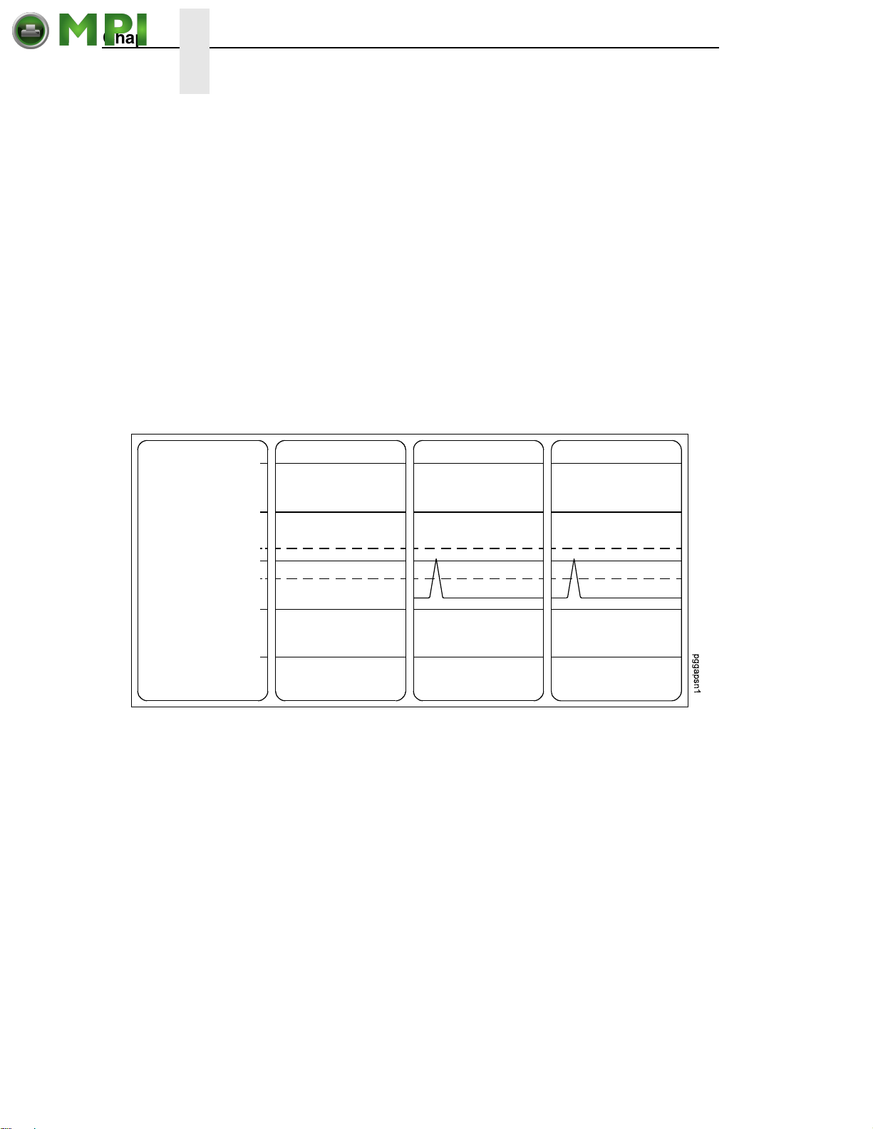
Chapter 2 Running Media Profile
Mantenimiento Periféricos Informáticos C/Canteras, 15 28860 Paracuellos de Jarama (Madrid) Tel: 00 34 917481604 Web: https://mpi.com.es/
4. Press ↵ to enter the SENSOR SETUP menu.
5. Press the Down key until Run Profile displays and then press ↵.
(The printer will continue to print the profile until you press ↵.)
The printer will advance media and continue to print a dynamic profile
image depicting the relationship of the label and any label length
indicators detected.
6. Press ↵. The printer will stop printing.
7. Press the Pause key until OFFLINE displays.
NOTE: The Gap/Mark and Paper Out Threshold values shown on the Profile
printout represent the last values determined from a successful Auto
or Manual Calibrate or the factory default values if no Auto or Manual
Calibrate was performed.
Label Feed Direction
Paper Out(167)
Gap (109)
Figure 22. This Illustration Shows a Media Profile Printout
255
191
127
063
000
In Figure 22, the tent shapped pulse immediately following the liner gap
shows that the gap was easily detected. A very low amplitude pulse may be
due to a dirty sensor or low contrast media where there is very little opacity
difference between the label and the liner gap.
52
Page 53

Running Manual Calibrate
Mantenimiento Periféricos Informáticos C/Canteras, 15 28860 Paracuellos de Jarama (Madrid) Tel: 00 34 917481604 Web: https://mpi.com.es/
Manual Calibrate should be performed only when the values derived from
Auto Calibrate fail to improve the media sensors’ ability to sense label length
indicators on the installed media. You must first enable Admin User in the
PRINTER SETUP menu before accessing or initializing Run Manual Cal
(manual calibrate) in the SENSOR SETUP menu.
NOTE: Verify the Gap/Mark Sensor option (Gap, Mark, or Disable) matches
the installed media. See
Ensure the media sensors are horizontally positioned to permit
sensing of the label length indicators. See
Sensors” on page 47.
Ensure the Print Mode option selected in the MEDIA SETUP menu
matches the media installed. Select Direct for heat sensitive media
(no ribbon required) or Transfer for thermal transfer media (ribbon
required).
If you try to do a Manual Calibrate when Peel-Off Media Handling is
enabled, the LCD will display, CANNOT CALIBRATE/Disable
Peel-Off. Before you can do a Manual Calibrate, you must select
another media handling mode or enable the Cal in Peel Mode option
under the SENSOR SETUP menu. Cal in Peel Mode displays only if
Admin User is enabled under the PRINTER SETUP menu.
.
1. Press to place the printer in Menu mode.
2. Press the Down + ↵ (Enter) keys together until “THE ↵ KEY IS
UNLOCKED” displays.
3. Press the Right key until PRINTER SETUP displays.
.
.
“Sensing Different Media Types” on page 49.
“Positioning The Media
4. Press ↵ to Enter the PRINTER SETUP menu.
5. Press Up key until Admin User displays, then press the Right key until
until Enable displays.
6. Press ↵ to select Enable. An asterisk (*) appears next to Enable.
.
7. Press to go back to the Main menu.
.
.
8. Press the Right key until SENSOR SETUP displays.
9. Press ↵ to Enter the SENSOR SETUP menu.
10. Press Down key until Run Manual Cal displays, then press the ↵.
11. Follow the instructions displayed on the LCD. Example: “REMOVE
MEDIA/Press Enter” indicates that you must open the pivoting deck and
remove the ribbon and media from under the printhead, close and lock
the pivoting deck, and press the
↵ key.
NOTE: When requested to load an item make sure to place the item in a
position where the media sensor can detect the item. For example,
when requested to “LOAD MARK” place the Mark (Black TOF Line) at
the media sensor.
53
Page 54

Chapter 2 Running Manual Calibrate
Mantenimiento Periféricos Informáticos C/Canteras, 15 28860 Paracuellos de Jarama (Madrid) Tel: 00 34 917481604 Web: https://mpi.com.es/
12. During the last step of Run Manual Cal, the printer advances the media
and attempts to detect the label length indicators and stop at the
Top-of-Form position. The Sensed Distance value will then display for
one second. The calibrate is successful when the Sensed Distance value
correctly matches that of the installed media. If “CALIBRATION FAIL/See
Manual” displays, run a manual calibrate again.
NOTE: The amount of media sampled during manual calibration is based on
the length of a label and the transitions detected without error,
between a label and its label length indicators.
13. Press the (Pause) key until OFFLINE displays.
14. Press the (Feed) key several times. Each time you presss the
media advances one label length and stops.
NOTE: After a form feed, the position of the leading edge of the next label
depends on the type of Media Handling mode selected under the
MEDIA SETUP menu. Tear-Off Strip Media Handling positions the
label edge at the tear bar, while Continuous positions the label edge
under the printhead.
15. Once the correct values are confirmed, save them to the desired
configuration menu before powering off the printer. See
Configuration” on page 147.
“Saving A
54
Page 55

3 Standard Interfaces
Mantenimiento Periféricos Informáticos C/Canteras, 15 28860 Paracuellos de Jarama (Madrid) Tel: 00 34 917481604 Web: https://mpi.com.es/
Overview
This chapter describes the host interfaces provided with the printer. The
printer interface is the point where the data line from the host computer plugs
into the printer. The interface processes all communications signals and data
to and from the host computer. Plus, with the Auto Switching feature, you can
configure the printer to accept several interfaces at the same time.
In addition to descriptions for the multi-line interfaces, this chapter also
provides instructions for configuration of terminating resistors for the parallel
and serial interfaces.
Auto Switching
This feature gives the printer the ability to handle multiple data streams
sequentially. With Auto Switching, the printer can service hosts attached to
the serial, parallel, USB, or Ethernet as if they were the only interface
connected.
For example, if the host computer sends one print job to the RS-232 serial
port and a separate print job to the IEEE 1284 parallel port, the printer's Auto
Switching will handle both jobs, in the order they were received, without the
user having to reconfigure the selected interface between jobs.
Standard Host Interfaces
• Centronics parallel
• IEEE 1284 parallel bidirectional port
• RS-232 Serial Port
• USB 2.0 Universal Serial Bus
Optional Host Interfaces
• Ethernet 10/100Base-T
• Wireless Ethernet
55
Page 56
Chapter 3 Centronics Parallel Interface
Mantenimiento Periféricos Informáticos C/Canteras, 15 28860 Paracuellos de Jarama (Madrid) Tel: 00 34 917481604 Web: https://mpi.com.es/
Centronics Parallel Interface
Table 4. Centronics Interface Connector Pin Assignments
Input Signals Output Signals Miscellaneous
Signal Pin Signal Pin Signal Pin
DATA LINE 1
Return
DATA LINE 2
Return
DATA LINE 3
Return
DATA LINE 4
Return
DATA LINE 5
Return
DATA LINE 6
Return
DATA LINE 7
Return
DATA LINE 8
Return
DATA STROBE
Return
PAPER INSTRUCTION
Return
PRIME
Return
2
20
3
21
4
22
5
23
6
24
7
25
8
26
9
27
1
19
15
29
31
30
ACKNOWLEDGE
Return
ONLINE
Return
FAULT
Return
PAPER EMPTY
Return
BUSY
Return
10
28
13
28
32
29
12
28
11
29
CHASSIS GROUND 17
GROUND 30
Spares 14
No Connection 34,35,
36
+5 Volts 18
NOTE: The length of the data cable from the host computer to the printer
must not exceed 15 feet (5 meters).
56
Page 57
Centronics Parallel Interface Signals
Mantenimiento Periféricos Informáticos C/Canteras, 15 28860 Paracuellos de Jarama (Madrid) Tel: 00 34 917481604 Web: https://mpi.com.es/
Centronics Parallel Interface Signals
Table 5. Centronix Parallel Interface Signals
Signals Purpose
Data Lines 1 through 8 Provide eight standard or inverted levels from
the host that specify character data, plot data,
or a control code. Data Line 8 allows access to
the extended ASCII character set. You may
enable or disable this line via the Data Bit 8
parameter on the Centronics Parallel submenu.
Data Strobe Carries a low true, 100 ns minimum pulse from
the host that clocks data into the printer.
Acknowledge A low true pulse from the printer indicating the
character or function code has been received
and the printer is ready for the next data
transfer.
Online A high true level from the printer to indicate the
printer is ready for data transfer and the Pause
key on the control panel has been activated.
When the printer is in online mode, it may
accept data from the host.
Paper Empty (PE) A high true level from the printer to indicate the
printer is in a paper empty or paper jam fault.
Busy A high true level from the printer to indicate the
printer cannot receive data.
Prime A high true level from the host to indicate the
printer should perform a warm start (printer is
reset to the power-up configuration values).
Paper Instruction (PI) Carries a VFU signal from the host with the
same timing and polarity as the data line.
Fault A low true level from the printer indicates a
printer fault.
57
Page 58

Chapter 3 IEEE 1284 Parallel Interface
Mantenimiento Periféricos Informáticos C/Canteras, 15 28860 Paracuellos de Jarama (Madrid) Tel: 00 34 917481604 Web: https://mpi.com.es/
IEEE 1284 Parallel Interface
The IEEE 1284 supports three operating modes, which are determined by
negotiation between the printer and the host.
Compatibility Mode
This mode provides compatibility with Centronics-like host I/O (see Table 4).
Data is transferred from the host to the printer in 8-bit bytes over the data
lines.
Compatibility Mode can be combined with Nibble and Byte Modes to provide
bidirectional communication.
Nibble Mode
Eight bits equals one byte. When a byte of data is sent to the printer, the eight
bits are sent over eight data lines.
Some devices cannot send data over their eight data lines. To bypass this,
the IEEE 1284 permits data to be sent as half a byte over four status lines.
(Half a byte equals one nibble.) Two sequential four-bit nibbles are sent over
the lines.
Data is transferred from printer to host in four-bit nibbles over the status lines,
and the host controls the transmission.
Byte Mode
The printer and host send data to each other along eight data lines (one bit
per line).
If bidirectional communication is supported by the printer and the host, the
host will take control of the data transfer.
58
Page 59
Signals
Mantenimiento Periféricos Informáticos C/Canteras, 15 28860 Paracuellos de Jarama (Madrid) Tel: 00 34 917481604 Web: https://mpi.com.es/
Table 6 lists each of the signals associated with the corresponding pins on the
IEEE 1284 interface. Descriptions of the signals follow.
Table 6. IEEE 1284 Signals
Type of Mode
Pin Source of Data
Compatible Nibble Byte
1 Host nStrobe HostClk Host/Clk
2 Host/Printer Data 1 (LSB)
3 Host/Printer Data 2
4 Host/Printer Data 3
5 Host/Printer Data 4
Signals
6 Host/Printer Data 5
7 Host/Printer Data 6
8 Host/Printer Data 7
9 Host/Printer Data 8 (MSB)
10 Printer nAck PtrClk PtrClk
11 Printer Busy PtrBusy PtrBusy
12 Printer PError AckDataReq AckDataReq
13 Printer Select Xflag Xflag
14 Host nAutoFd Host Busy HostAck
15 Not Defined
16 Logic Grid
17 Chassis Grid
18 Printer Peripheral Logic High
19 Signal Ground (nStrobe)
20 Signal Ground (Data 1)
21 Signal Ground (Data 2)
22 Signal Ground (Data 3)
23 Signal Ground (Data 4)
24 Signal Ground (Data 5)
25 Signal Ground (Data 6)
59
Page 60
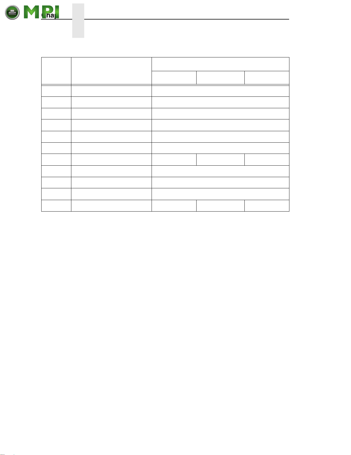
Chapter 3 IEEE 1284 Parallel Interface
Mantenimiento Periféricos Informáticos C/Canteras, 15 28860 Paracuellos de Jarama (Madrid) Tel: 00 34 917481604 Web: https://mpi.com.es/
Table 6. IEEE 1284 Signals (continued)
Type of Mode
Pin Source of Data
Compatible Nibble Byte
26 Signal Ground (Data 7)
27 Signal Ground (Data 8)
28 Signal Ground (PError, Select, nAck)
29 Signal Ground (Busy, nFault)
30 Signal Ground (nAutoFd, nSelectIn, nInit)
31 Host nInit
32 Printer NFault nDataAvail aDataAvail
33 Not Defined
34 Not Defined
35 Not Defined
36 Host nSelectIn 1284 Active 1284 Active
NOTE: The length of the data cable from the host computer to the printer
should not exceed 32 feet (10 meters).
Host Clock / nWrite. Driven by the host. Data is transferred from the host to
the printer. When the printer sends data, two types are available. If it is Nibble
Mode, the signal is set high. If it is Byte Mode, the signal is set low.
Data 1 through Data 8. These pins are host-driven in Compatibility Mode and
bidirectional in Byte Mode. They are not used in Nibble Mode. Data 1 is the
least significant bit; Data 8 is the most significant bit.
Printer Clock / Peripheral Clock / Interrupt. Driven by the printer. A signal
from the printer indicating the character or function code has been received
and the printer is ready for the next data transfer.
Printer Busy / Peripheral Acknowledge / nWait. Driven by the printer.
Indicates the printer cannot receive data. (Data bits 4 and 8 in Nibble Mode.)
Acknowledge Data Request / nAcknowledge Reverse. Driven by the
printer. Indicates the printer is in a fault condition. (Data bits 3 and 7 in Nibble
Mode.)
Xflag. Driven by the printer. A high true level indicating the printer is ready for
data transfer and the printer is online. (Data bits 2 and 6 in Nibble Mode.)
Host Busy / Host Acknowledge / NDStrobe. Driven by the host. Activates
auto-line feed mode.
Peripheral Logic High. Driven by the printer. When the line is high, the
printer indicates all of its signals are in a valid state. When the line is low, the
printer indicates its power is off or its signals are in an invalid state.
60
Page 61
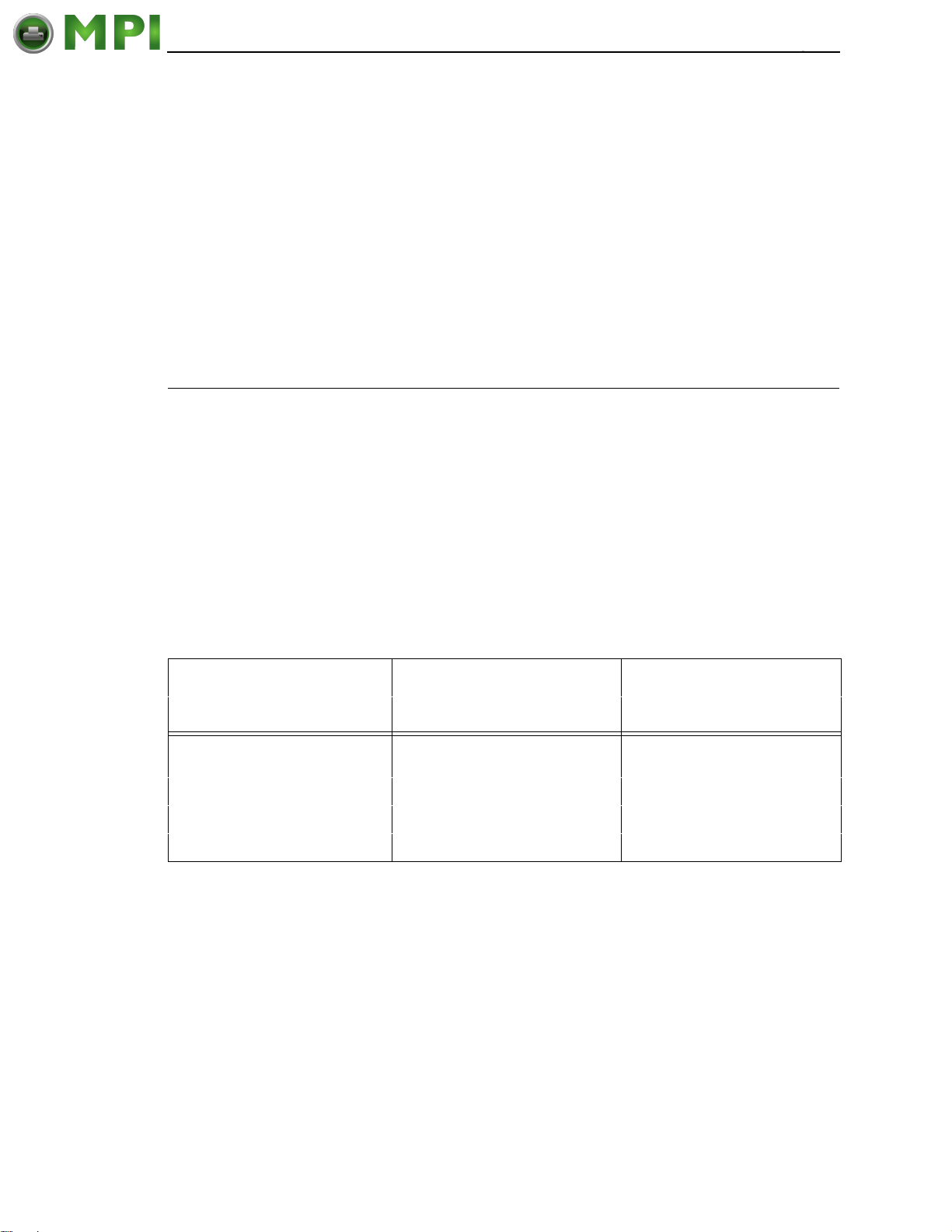
nReverse Request. Driven by the host. Resets the interface and forces a
Mantenimiento Periféricos Informáticos C/Canteras, 15 28860 Paracuellos de Jarama (Madrid) Tel: 00 34 917481604 Web: https://mpi.com.es/
return to Compatibility Mode idle phase.
nData Available / nPeripheral Request. Driven by the printer. Indicates the
printer has encountered an error. (Data bits 1 and 5 in Nibble Mode.)
1284 Active / nAStrobe. Driven by the host. A peripheral device is selected.
Host Logic High. Driven by the host. When set to high, the host indicates all
of its signals are in a valid state. When set to low, the host indicates its power
is off or its signals are in an invalid state.
nInit. Resets init interface from the host.
RS-232 Serial Interface
RS-232 Serial Interface
Signals
NOTE: The RS-232 serial interface circuit characteristics are compatible with
the Electronic Industry Association Specification EIA
®
-232-E.
The RS-232 serial interface enables the printer to operate with bit serial
devices that are compatible with an RS-232 controller. The input serial data
transfer rate (in baud) is selectable from the printer's control panel. Baud rates
of 600, 1200, 2400, 4800, 9600, 19200, 38400, 57600, and 115200 are
available.
The length of the data cable from the host computer to the printer must not
exceed 50 feet (15 meters) for RS-232
Table 7. RS-232 Serial Interface Connector (9 Pin) Assignments
Input Signals Output Signals Miscellaneous
Signal Pin Signal Pin Signal Pin
Receive Data (RXD) 2 Transmit Status & Control
Data (TXD)
Clear To Send (CTS) 8 Request To Send (RTS) 7
Data Set Ready (DSR) 6 Data Terminal Ready (DTR) 4
Data Carrier Detect (DCD) 1
3 Chassis/Signal Ground 5
Received Data (RXD). Serial data stream to the printer.
Transmitted Data (TXD). Serial data stream from the printer for transmitting
status and control information to the host. Subject to protocol selection.
Request To Send (RTS). Control signal from the printer. Subject to
configuration.
Clear To Send (CTS). Status signal to the printer indicating the host is ready
to receive data/status signals from the printer.
Data Set Ready (DSR). Status signal to the printer indicating the host is in a
ready condition.
61
Page 62

Chapter 3 RS-232 Serial Interface
Mantenimiento Periféricos Informáticos C/Canteras, 15 28860 Paracuellos de Jarama (Madrid) Tel: 00 34 917481604 Web: https://mpi.com.es/
Data Carrier Detect (DCD). Status signal to the printer. The ON condition is
required for the printer to receive data.
Data Terminal Ready (DTR). Control signal from the printer. Subject to
configuration.
62
Page 63

4 Configuring The Printer
Mantenimiento Periféricos Informáticos C/Canteras, 15 28860 Paracuellos de Jarama (Madrid) Tel: 00 34 917481604 Web: https://mpi.com.es/
Overview
This chapter provides information about:
• Setting, saving, modifying, and printing configurations
• Configuration menus
Setting Printer Configuration Parameters
Configuration parameters are set from the control panel or are retrieved from
the printer’s memory. The parameters define how the printer will respond to
command and interface signals from the host computer.
The configuration menu structure consists of main menus and the options
applicable to each menu.
NOTE: Some configurations refer to printer options that may not be present
in your printer. If you select an option or feature that is not present, no
action will be performed by the printer or an “OPTION NOT
INSTALLED” message will display on the LCD.
Moving Within The Configuration Menu
You can navigate through the configuration menus using the appropriate
navigation keys, as shown in
page 37 for more details on the function of the operator panel keys.)
You can select different options and save them as the power on default;
however, you can only save them to configuration menus 1-8. The factory
configuration menu can be altered, but not saved.
When the printer is online, the first line of the LCD displays “ONLINE” and the
second line lists the active interface port and emulation type.
To configure the printer:
.
1. Press the key to enter the printer menu system. Eight menu icons
display on the LCD. The MEDIA SETUP icon is selected (highlighted).
2. You can move through configuration main menus in two ways:
.
.
• Press the right key to move right or the left key to move left.
• Press the down key to move down or the up key to move up between
menu icons displayed within each column.
Figure 16. (See “Controls And Indicators” on
63
Page 64
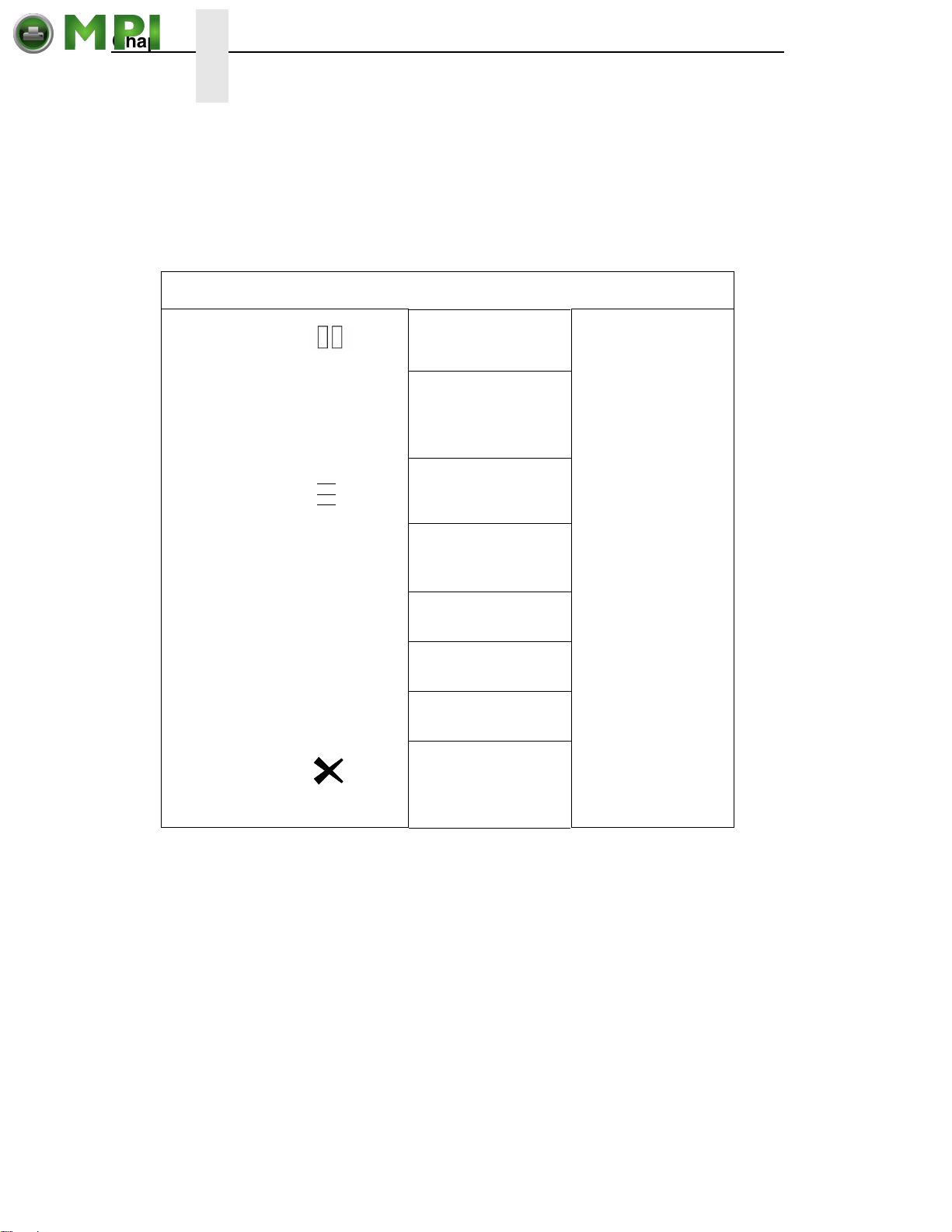
Chapter 4 Overview
Mantenimiento Periféricos Informáticos C/Canteras, 15 28860 Paracuellos de Jarama (Madrid) Tel: 00 34 917481604 Web: https://mpi.com.es/
NOTE: In menus with numeric ranges of more than 50 numbers, hold down
Step Press LCD Notes
1 OFFLINE
the right or left key for more than 2 seconds to move through the
range in increments of 5. To move in increments of 1 again, release
your hold on the right or left key.
Table 8: Keys for Menu Navigation
2
3 MEDIA SETUP Enters the printer
4
5 DOWN Key UNTIL Print Mode:
6 LEFT Key or
7
8
DOWN Key+ ↵ THE ↵ KEY IS
UNLOCKED
.
.
.
↵
RIGHT Key
↵
MEDIA SETUP
Print Intensity:
Transfer*
Print Mode:
Print Mode
Direct*
MEDIA SETUP
Print Intensity:
Direct
Unlocks the ENTER
key to allow you to
make configuration
changes.
menus.
Enters the MEDIA
SETUP Menu.
-3*
Print Mode is
selected.
Cycles through the
choices.
Selects the Direct
transfer mode.
In Menu mode, this
key moves up to the
previous higher level
menu.
64
Page 65

Selecting A Menu Option
Mantenimiento Periféricos Informáticos C/Canteras, 15 28860 Paracuellos de Jarama (Madrid) Tel: 00 34 917481604 Web: https://mpi.com.es/
Selecting A Menu Option
To select an option, you need to press the ↵ key. By default, however, the
↵ key is “locked” when the printer is turned on to prevent accidental changes
to the configuration menu. If you press the ↵ key when the key is locked, the
message “The
the value will not be selected.
To unlock the ↵ key, press the Down + ↵ (Enter) keys simultaneously (if the
combination keys have not been otherwise reconfigured). This toggles the
ENTER/LOCK function.
• If this function is performed while the ↵ key is locked, the message
“The ↵ KEY IS UNLOCKED” displays for one second, and the ↵ key will
be unlocked.
• If this function is performed while the ↵ key is unlocked, the message
“The
locked.
When you press the ↵ key (with the ↵ key unlocked), you select the value or
option that displays. An asterisk displays after the value you selected, and the
configuration is changed immediately.
↵ KEY IS LOCKED” displays on the LCD for one second and
↵ KEY IS LOCKED” displays for one second, and the ↵ key will be
IMPORTANT
This change takes effect for all subsequent data and operations for the
printer as soon as the
The configuration change(s) stay in effect only while the printer is
powered on. When the power is turned off, all current configurations will
be lost unless changes made to it are saved via the CONFIGURATION
menu. To save configuration information permanently or to select it as
the power-up default, see
When you make a menu change and attempt to go Online without saving
the changes to a configuration, you will be prompted to save the
changes (provided that Auto Save is set to Enable in the
CONFIGURATION MENU). For more information on Auto Save
Configuration, see
↵ key is pressed and the asterisk (*) is displayed.
“Saving A Configuration” on page 147.
page 148.
65
Page 66

Chapter 4 Overview
Mantenimiento Periféricos Informáticos C/Canteras, 15 28860 Paracuellos de Jarama (Madrid) Tel: 00 34 917481604 Web: https://mpi.com.es/
Changing Printer Settings
You can change (or “configure”) printer settings, such as print speed or
emulations, through the control panel as follows:
1. Press the key to enter the Menu configuration. MEDIA SETUP is
selected.
2. Press the ↵ key to enter the MEDIA SETUP menu. Print Intensity is
selected.
3. Press the Down key to cycle through these options:
• Print Intensity
• Print Speed
• Print Mode
• Media Handling
• Tea r Off A dj us t
• Label Length
.
.
.
IMPORTANT
• Label Width
• Ver Image Shift
• Hor Image Shift
• Orientation
• Units
4. When the desired submenu is selected, press the Left or Right keys to
scroll through the values or options.
5. Press the ↵ key to select a value. An asterisk (*) displays next to the
selected value or option.
6. If there are more submenu values or options you want to change, use the
.
.
,Up, Down, Left, and Right keys to access the value and the ↵ key to
.
select it. At any time, you may press the key to return to the Main
menu.
7. At any time, you may press the Pause key twice to exit the Configuration
menu and place the printer online. Once you have finished selecting all
your options, save your configuration.
If you do not save your configuration, all your new values will be lost
when you power off the printer. See
page 147 and “Auto Save Configuration” on page 148.
.
.
.
“Saving A Configuration” on
66
Page 67
Hidden Menus
Mantenimiento Periféricos Informáticos C/Canteras, 15 28860 Paracuellos de Jarama (Madrid) Tel: 00 34 917481604 Web: https://mpi.com.es/
By default, menu items for advanced users are hidden (they do not appear in
the menu structure). To display these hidden menus:
1. Press to enter Menu mode.
2. Press the Down and ↵ keys at the same time until THE ↵ KEY IS
3. Press the Right key until PRINTER SETUP displays.
4. Press ↵ to enter the PRINTER SETUP menu.
5. Press the Up key until Admin User displays.
6. Press the Right key until Enable displays.
7. Press ↵ to select it. An asterisk (*) displays after Enable. The hidden
8. If there are more submenu values or options you want to change, use the
9. At any time, you may press the Pause key twice to exit the Configuration
Changing Printer Settings
UNLOCKED displays.
menus will now appear.
.
.
,Up, Down, Left, and Right keys to access the value and the ↵ key to
.
select it. At any time, you may press the key to return to the Main
.
.
.
menu.
menu and place the printer online. Once you have finished selecting all
your options, save your configuration.
IMPORTANT
If you do not save your configuration, all your new values will be lost
when you power off the printer. See
“Saving A Configuration” on
page 147 and “Auto Save Configuration” on page 148.
67
Page 68
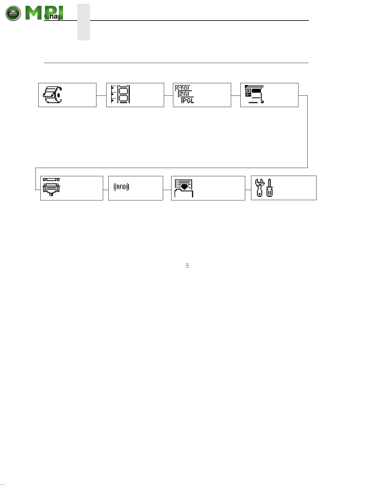
Chapter 4 Menu Overview
Mantenimiento Periféricos Informáticos C/Canteras, 15 28860 Paracuellos de Jarama (Madrid) Tel: 00 34 917481604 Web: https://mpi.com.es/
Menu Overview
MEDIA
SETUP
Control various
parameters related to
print quality, media, and
ribbon.
INTERFACES
Set host interfaces.
SENSOR
SETUP
Select the correct
media sensing for the
media type installed
and perform media
sensor calibration.
RFID
Setup and status
reporting for RFID
encoder if installed.
EMULATION
Select the desired
Active IGP emulation,
other emulations, and
various printer
operating parameters.
CONFIGURATION
Name, store, and retrieve up
to eight custom printer
configurations.
.
Press to select the next main menu.
.
.
Press the Up or Down keys to move within each main menu.
Set the menus needed
to configure the
printer.
PRINTER
SETUP
DIAGNOSTICS
Select various printer
tests, monitor and record
printer performance.
68
Page 69
Main Menu
Mantenimiento Periféricos Informáticos C/Canteras, 15 28860 Paracuellos de Jarama (Madrid) Tel: 00 34 917481604 Web: https://mpi.com.es/
MEDIA
SETUP
(page 71)
Print Intensity
Print Speed
Print Mode
Media Handling
Adv Continuous
Tear Off Adjust
Label Length
Label Width
Ver Image Shift
Hor Image Shift
Orientation
Auto Map Select
Auto Label Width
Num Auto Labels
Slew Speed Ctrl
Slew Speed
Print Direction
Label Wait Time
Label Missing
Clip Page
Fault Reprint
Ribbon Low
Units
Set Label Length
TOF Detect Fault
Ticket Save Mode
TOF Adjust Mode
TOF Adjust
NOTES:
Italicized items are available only Admin User is set to Enable (in the
PRINTER SETUP menu).
1
This menu appears only if the RFID option is installed and no user defined CST
is loaded.
2
This menu appears only if a CST (Character Sequence Table) file is loaded.
3
This menu appears only if an EMC (Expanded Memory Cartridge) is installed.
4
This menu appears when Slew Speed Ctrl is set to Manual (in the MEDIA SETUP
menu).
5
This menu appears only if the real time clock option is installed.
6
Updates the set parameters only if the real time clock option is installed.
4
SENSOR
SETUP
(page 87)
Gap/Mark Sensor
Run Auto-Cal
Run Profile
Sensed Distance
Gap/Mark Thresh
Paper Out Thresh
Run Manual Cal
Pwr up Action
Head Auto-Cal
Online Auto-Cal
Gap Windowing
Gap Length
Cal in Peel Mode
Min Calib Delta
Use Label Length
Threshhold Range
Mark TOF Detect
Select
Emulation Setup
xxx Diagnostics
EMULATION
(page 94)
PRINTER
SETUP
(page 109)
5, 6
1
2
3
SMT: Status
PAA: Status
Power Saver Time
Pwr Save Control
Display Language
Alarm
Power-up State
PTX Setup Parse
Ptx Setup SFCC
Cancel Key
Ret. Status Port
Compatibility
Del Char frm Fls
Ld char from Fls
Save Char to Fls
Del Char frm RAM
Ld Char at PwrUp
Del Set frm Fls
Ld Set from Fls
Save Set to Fls
Del Set from RAM
Ld Set at PwrUp
Main FFS
EMC FFS
Optimize&Reboot
Print File List
Auto Locking
Set Lock Key
Max Font Buffer
Max Cache Memory
Max Cached Char
Standard Chars.
Bold Chars.
Extra Bold Char.
OCR-A Chars.
OCR-B Chars.
Tall Characters
Batch Counter
Date
Disp. Intensity
Bot Line Display
Admin User
69
Page 70
Chapter 4 Main Menu
Mantenimiento Periféricos Informáticos C/Canteras, 15 28860 Paracuellos de Jarama (Madrid) Tel: 00 34 917481604 Web: https://mpi.com.es/
INTERFACE
(page 120)
Host Interface
ETHERNET PORT
ETHERNET SETTING
WLAN SETTING
Parallel Port
CENTRONICS
IEEE 1284
USB Port
4
5
6
7
Serial Port
Printer Mgmt
RFID
Refer to the
Labeling Reference
3
Manual.
RFID
CONFIGURATION
(page 141)
Save Config.
Load Config.
Print Config.
Delete Config.
Power-Up Config.
Protect Configs.
Name Config 1
Name Config 2
Name Config 3
Name Config 4
Name Config 5
Name Config 6
Name Config 7
Name Config 8
Reset Cfg Names
Auto Save
DIAGNOSTICS
(page 144)
Printer Tests
Test Count
Software Build
Feature File
Hex Dump Mode
Print Error Log
Clear Error Log
FLASH Installed
EMC FLASH Installed
1
2
DRAM Installed
Ptr On Time
Printer Usage
PrintHead Usage
Head On Time
Reset Head Data
Head Resolution
Head Voltage
NOTES:
Italicized items are available only when you enable Admin User in the
PRINTER SETUP menu.
1
This menu only appears if Feature File is loaded.
2
This menu only appears only if the EMC is installed.
3
This menu only appears only if the ethernet is installed.
4
This menu only appears only if the wireless ethernet is installed.
5
This menu only appears if Host Interface is set to Auto Switching.
6
This menu only appears if Host Interface is set to Centronics.
7
This menu only appears if Host Interface is set to IEEE 1284.
70
Page 71
MEDIA SETUP Menu
Mantenimiento Periféricos Informáticos C/Canteras, 15 28860 Paracuellos de Jarama (Madrid) Tel: 00 34 917481604 Web: https://mpi.com.es/
MEDIA
SETUP
(from page 69)
Print Intensity Print Speed Print Mode
0*
-15 to 15
Label Length
6 inches*
0.1 to 99.0 inches
Auto Label
Width
4.1 inches*
00.1 to 4.1 inches
Label Missing
Fault Disable*
Fault Enable
1
1
4 ips*
1 ips to 10 ips
Label Width
4.1 inches *
0.1 to 4.1 inches
2 labels*
1 to 40 labels
Clip Page
Enable*
Disable
Num Auto
Labels
Transfer*
Direct
1
6
Fault Reprint
Disable*
Enable
Ver Image
0.00 inches
-1.00 to X
Slew Speed
Automatic*
Manual
Shift
2
Ctrl
Media
Handling
Tear-Off Strip*
Peel-Off
Cut
Rewind
Continuous
Hor Image
Shift
1
0.00 inches*
-1.00 to 1.00
Slew Speed
4 ips*
1 to 10 ips
Ribbon Low
Disable*
Enable
Standard*
Tear-Off
Tear Strip Full
Cut Strip
1
5
Adv
Continuous
Orientation
Portrait*
Landscape
Inv. Portrait
Inv. Landscape
Print Direction
Head First*
Foot First
Units
In Inches*
In Millimeters
0.00*
-1.00 to 0.20
Tear Off
Adjust
Auto Map
Select
Disable*
Enable
Label Wait
Time
0.1 seconds*
00.1 to 60.0 seconds
Set Label
Length
Manual*
Automatic
TOF Detect
Fault
3 Labels*
9 Labels
Ticket Save
Mode
Disable*
Enable
TOF Adjust
Mode
Disable*
Enable
TOF Adjust
0.40 inches*
0.00 to 0.40 inches
4
1 Label
Notes:
* = Factory Default
Italicized items are available when Admin User is set to Enable in the PRINTER SETUP menu.
1
You can change the unit value from inches to millimeters under Units (in MEDIA SETUP) when Admin User is set to
Enable (in the PRINTER SETUP menu).
2
Based on the current value setting for Label Length (in the MEDIA SETUP menu) up to a maximum of 12.80 inches.
3
Maximum value depends on the amount of DRAM available for page memory, label length, and label width
(see Appendix A, “Specifications”).
4
In increments of 0.01 inch.
5
This menu appears when Slew Speed Ctrl is set to Manual (in the MEDIA SETUP menu).
71
Page 72

Chapter 4 MEDIA SETUP Menu
Mantenimiento Periféricos Informáticos C/Canteras, 15 28860 Paracuellos de Jarama (Madrid) Tel: 00 34 917481604 Web: https://mpi.com.es/
MEDIA SETUP Submenus
Print Intensity
This option specifies the level of thermal energy from the printhead to be used
for the type of media and ribbon installed.
Large numbers imply more heat (thermal energy) to be applied for each dot.
This has a significant effect on print quality. The print intensity and speed
must match the media and ribbon type to obtain the best possible print quality
and barcode grades.
The range is -15 to 15.
The factory default is 0.
Print Speed
This option specifies the speed in inches per second (ips) at which the media
passes through the printer while printing.
The range is 1 to 10 ips (in increments of 1 ips).
The factory default is 4 ips.
Print Mode
This option specifies the type of printing to be done.
• Transfer (factory default). Indicates Thermal Transfer printing (ribbon
installed).
• Direct. Indicates Direct Thermal printing (no ribbon) and requires special
heat sensitive media.
Media Handling
This option specifies how the printer will handle the media (labels or tag
stock).
• Tear-Off Strip (factory default). Printer prints on the media and sends it
out the front until the print buffer is empty, then positions the last label
(cross perforation following) over the tear bar for removal.
• Peel-Off. Prints and peels die-cut labels from the liner without assistance.
The printer waits for you to take away the label before printing the next
one (on-demand printing). Supported only when Standard Peel or
Peel with Liner Rewinder option is installed. When either option is
installed, a “Remove Label” message will display to remind you to remove
the label before the next one can be printed.
NOTE: If the Peel-Off option is not installed, the error message “OPTION
NOT INSTALLED” displays. Requires the Standard Peel without
Liner Rewinder or Standard Peel with Liner Rewinder option. Not
allowed if the options are not installed.
72
Page 73

MEDIA SETUP Submenus
Mantenimiento Periféricos Informáticos C/Canteras, 15 28860 Paracuellos de Jarama (Madrid) Tel: 00 34 917481604 Web: https://mpi.com.es/
• Cut. When the optional media cutter is installed, it automatically cuts
media after each label is printed or after a specified number of labels
have been printed when a software cut command has been issued. It cuts
continuous roll paper, labels, or tag stock.
NOTE: The Cut option is not allowed if the cutter is not installed. The error
message “OPTION NOT INSTALLED” displays.
• Rewind. In rewind mode the printer unwinds the media from the media
supply spindle or fanfold label stack, prints the labels, and rewinds the
printed media and its carrier web onto the optional rewind spindle.
NOTE: The Batch Label Rewinder option is not allowed if the rewinder is not
installed. The error message “OPTION NOT INSTALLED” displays.
• Continuous. Printer prints on the media until the print buffer is empty and
then stops at the next top of form.
Adv Continuous
Allows selection of special media modes when Continuous Media Handling
mode (see
page 72) is selected.
• Standard (factory default). Labels are printed and sent out the front. The
cross perforation following the last printed label is not aligned at the tear
bar. No auto feeding of a blank label should exist between print jobs, but
you may need to press the Feed key to move approximately .80 inches of
the last printed label from under the printhead. If performed, this feed
causes a blank label at the beginning of the next print job.
• Tear-Off. Same as Standard, but the cross perforation following the last
printed label is aligned at the tear bar. No blank label is needed to remove
the last printed label. No blank label should exist between print jobs. A no
print zone, .80 inches long, exists from the leading edge of each printed
label. This option supports label lengths 2.50 inches or longer.
• Tear Strip Full. Same as Standard, but the cross perforation following
the last printed label is automatically aligned at the tear bar once the print
buffer is empty for a period of Label Wait Time. (Media does not get
aligned at tear bar until Tear-Strip Time expires.) When printable data is
again detected, a blank label is automatically fed, resulting in one blank
label between each print job. This option supports label lengths 2.50
inches or longer. Shorter label lengths cause two or more blank labels to
be automatically fed at the beginning of each print job.
• Cut Strip. Same as Standard, but the cross perforation following the last
printed label is automatically aligned to the cut position once the print
buffer is empty for a period of Label Wait Time. (Media does not get
aligned at the cut position until Label Wait Time expires.) When printable
data is again detected, a blank label is automatically fed, resulting in one
blank label between each print job. This option supports label lengths
2.50 inches or longer. Shorter label lengths cause two or more blank
labels to be automatically fed at the beginning of each print job.
73
Page 74

Chapter 4 MEDIA SETUP Menu
Mantenimiento Periféricos Informáticos C/Canteras, 15 28860 Paracuellos de Jarama (Madrid) Tel: 00 34 917481604 Web: https://mpi.com.es/
Tear Off Adjust
This option represents the distance to advance (+ shift) or pull back (– shift)
the stop position of a label when Tear-Off Strip, Peel-Off, or Cut media
handling option is enabled. The allowable range is -1.00 inches to
+ 0.2 inches, in .01 inch increments.
The factory default is 0.00 inches.
Label Length
This option specifies the user-selected Label Length in inches or millimeters.
In most applications, the user-selected Label Length will match the physical
label length. Physical label length is the actual label length of the media
installed.
When setting label length, consider the following:
Label Length can also be manually entered via the control panel MEDIA
SETUP menu or sent via host computer using the appropriate software
command.
A Host Forms Length (Label Length) value sent from the host computer will
override and change the manually entered Label Length value in the MEDIA
SETUP menu.
• Physical Label Length is the actual measurable length of the label. The
following list of different media types explains how the physical label
lengths are determined:
• Die-cut labels – measurable length of the removable label (leading
edge to trailing edge). This does not include the liner material or gap.
• Tag Stock with notches or holes – measurable length from the trailing
edge of one notch or hole to the leading edge of the next notch or
hole.
• Tag Stock with black marks on underside – measurable length from
the trailing edge of one black mark to the trailing edge of the next
black mark.
NOTE: The printer can be configured to detect the leading edge of the black
mark using the Mark TOF Detect option in the SENSOR SETUP
menu.
• Continuous media (no label length indicators) – measurable length
should be within
SETUP menu, or the value sent via host software command.
+ 1-2% the Label Length value entered in the MEDIA
• Logical Label Length (Host Forms Length) is the length that a user or
programmer bases his printable image on. In most cases this length
should be slightly less than the Physical Label Length. This allows the
entire image to be printed within the boundaries of the label length
indicators (gaps, notches, holes, or black marks).
When the Logical Label Length is greater than the Physical Label Length
and Clip Page = Enable (in the MEDIA SETUP menu), the printer will clip
the bottom portion of the image that exceeds the Physical Label length. In
this case, the printable data that was not printed will be lost.
74
Page 75
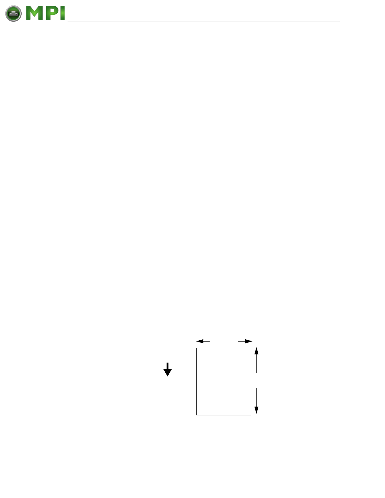
MEDIA SETUP Submenus
Mantenimiento Periféricos Informáticos C/Canteras, 15 28860 Paracuellos de Jarama (Madrid) Tel: 00 34 917481604 Web: https://mpi.com.es/
When the Logical Label Length is greater than the Physical Label Length
and Clip Page = Disable, the printer will continue to print the image onto
the next physical label and ignore the gap or mark based on the label
length value set in the MEDIA SETUP menu.
When the Logical Label Length is less than the Physical Label Length, the
printer will print the entire image and leave blank the remaining length of
the physical label as it advances to the Top-of-Form of the next label. This
is true regardless of the Clip Page setting.
The allowable Label Length range is 00.1 to 99.0 inches (2.5 - 2514.6mm).
The factory default is 6 inches. Maximum Label Length range is dependent on
the Label Width value selected, printhead installed (203 or 305 DPI).
NOTE: See “Set Label Length” on page 85.
Label Width
This option specifies the physical width of the image to be printed. The value
can be specified in inches or millimeters depending on the setting of the Units
submenu under the MEDIA SETUP menu. The allowable range in inches is
0.1 to 4.1 inches. The allowable range in millimeters is 2.5 to 104 mm.
Ver Image Shift
This option specifies the amount to shift an image vertically up (-) toward the
leading edge or down (+) toward the trailing edge for precise positioning on
the label. The actual height of the image is not affected by this parameter.
The allowable range is -1.00 inches to the current Label Length value setting,
up to a maximum of 12.80 inches, in .01 inch increments.
The factory default value is 0.00 inches.
Hor Image Shift
This option specifies the amount to shift an image horizontally outboard (-) or
inboard (+) for precise positioning on the label. The actual width of the image
is not affected by this parameter. The allowable range is -1.00 to +1.00 inches
in .01 inch increments.
The factory default value is 0.00 inches.
4 inches
FEED
6 inches
(+) A (-)
Leading Edge
Figure 23. This Illustration Shows the Direction of an Image Being Shifted Horizontally
75
Page 76
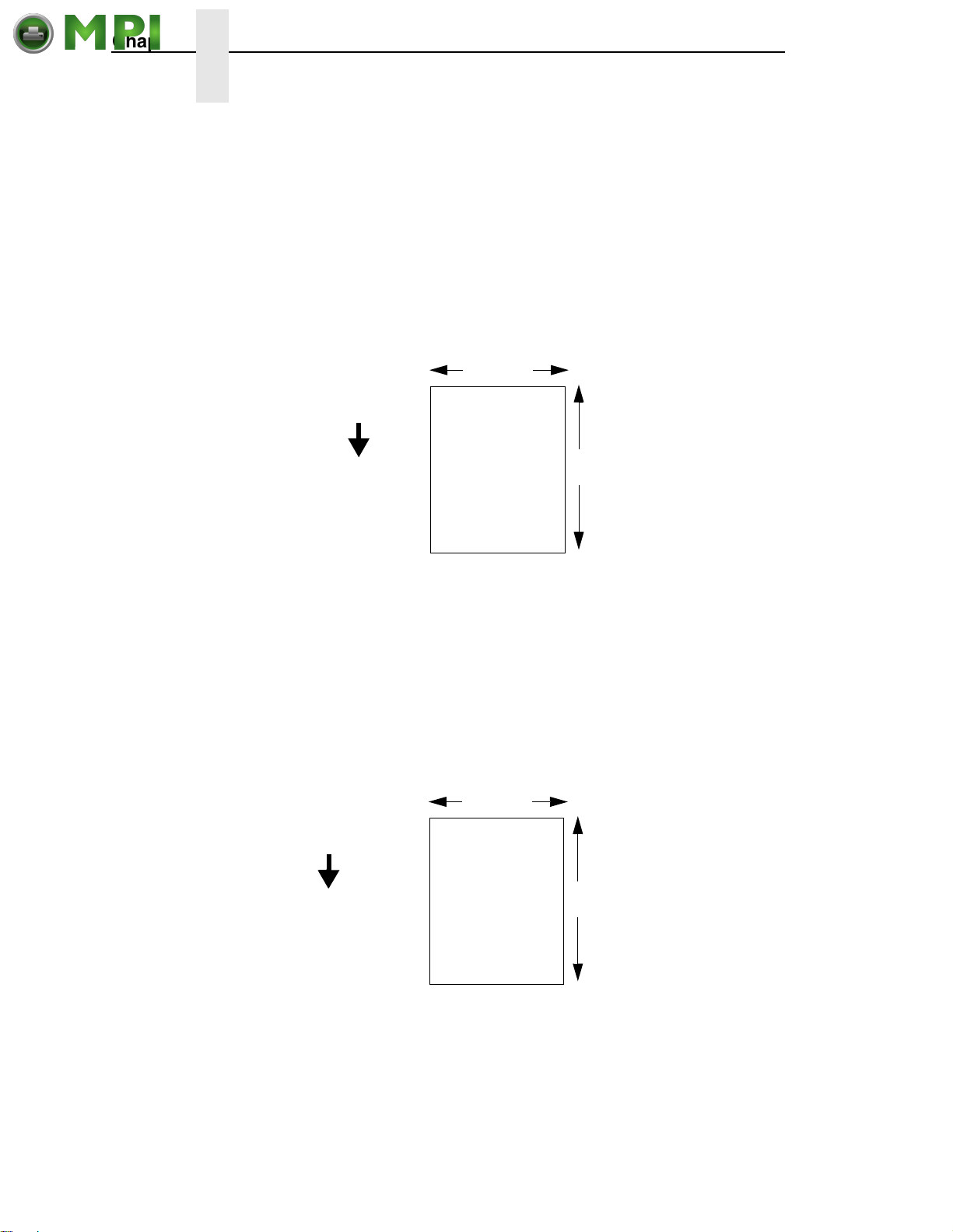
Chapter 4 MEDIA SETUP Menu
Mantenimiento Periféricos Informáticos C/Canteras, 15 28860 Paracuellos de Jarama (Madrid) Tel: 00 34 917481604 Web: https://mpi.com.es/
Orientation
This menu item selects the image orientation to be used when printing the
label.
• Portrait. Portrait refers to vertical page orientation, where the height of a
page is greater than its width. The top edge of the image is parallel to the
leading edge of the media. The following illustration is an example, with
the operator viewing the front of the printer.
NOTE: Portrait orientation applies to the PGL emulation. This is regarded as
Inverse Portrait using ZGL.
FEED
4 inches
the media.
6 inches
leading edge of
parallel to the
the image is
The top edge of
Leading Edge
Figure 24. This Illustration Demonstrates Portrait Image Orientation or Vertical Page
Orientation
• Landscape. Landscape refers to horizontal orientation, where the width
of a page is greater than its height. The top edge of the image is the left
edge of the media. The following illustration is an example, with the
operator viewing the front of the printer.
NOTE: Landscape orientation applies to the PGL emulation. This is regarded
as Inverse Landscape using ZGL.
4 inches
FEED
6 inches
The top edge of
the image is
parallel to the left
edge of the media.
Leading Edge
Figure 25. This Illustration Demonstrates Landscape Image Orientation or Horizontal Page
Orientation
76
Page 77
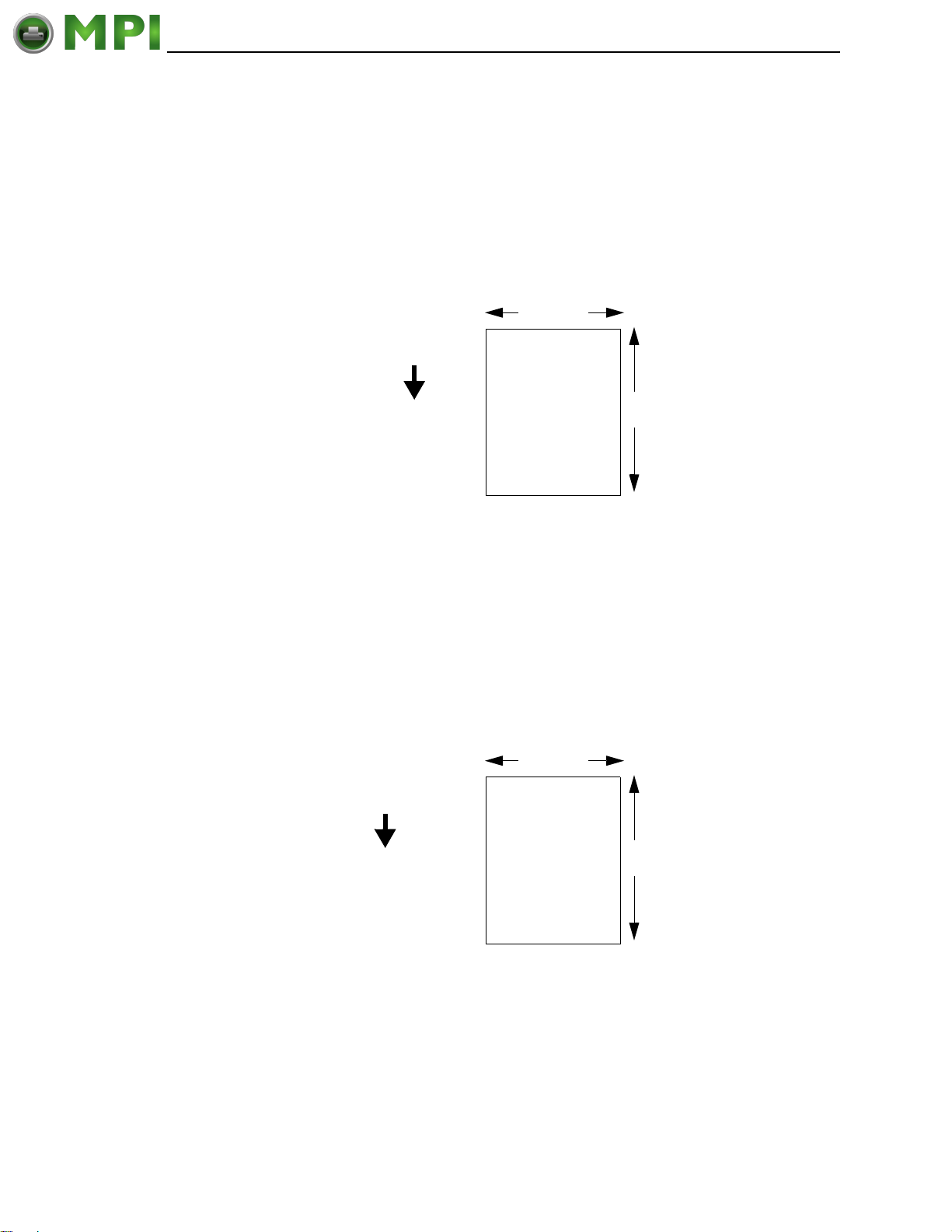
MEDIA SETUP Submenus
Mantenimiento Periféricos Informáticos C/Canteras, 15 28860 Paracuellos de Jarama (Madrid) Tel: 00 34 917481604 Web: https://mpi.com.es/
• Inv. Portrait. Inverse Portrait refers to vertical page orientation, where the
height of a page is greater than its width. The top edge of the image is
parallel to the trailing edge of the media. The following illustration is an
example, with the operator viewing the front of the printer.
NOTE: Inverse Portrait orientation applies to the PGL emulation. This is
regarded as Portrait using ZGL.
Trailing Edge
4 inches
FEED
Figure 26. This Illustration Demonstrates Inverse Portrait Image Orientation or Vertical
Page Orientation
The top edge of
the image is
parallel to the
trailing edge of the
media.
Leading Edge
6 inches
• Inv. Landscape. Inverse Landscape refers to horizontal orientation,
where the width of a page is greater than its height. The top edge of the
image is the right edge of the media (the left edge of the image is the
trailing edge of the media). The factory default is Portrait. The following
illustration is an example, with the operator viewing the front of the printer.
NOTE: Inverse Landscape orientation applies to the PGL emulation. This is
regarded as Landscape using ZGL.
4 inches
The top edge of
the image is
parallel to the right
FEED
edge of the media.
6 inches
Leading Edge
Figure 27. This Illustration Demonstrates Inverse Landscape Image Orientation or
Horizontal Page Orientation
77
Page 78
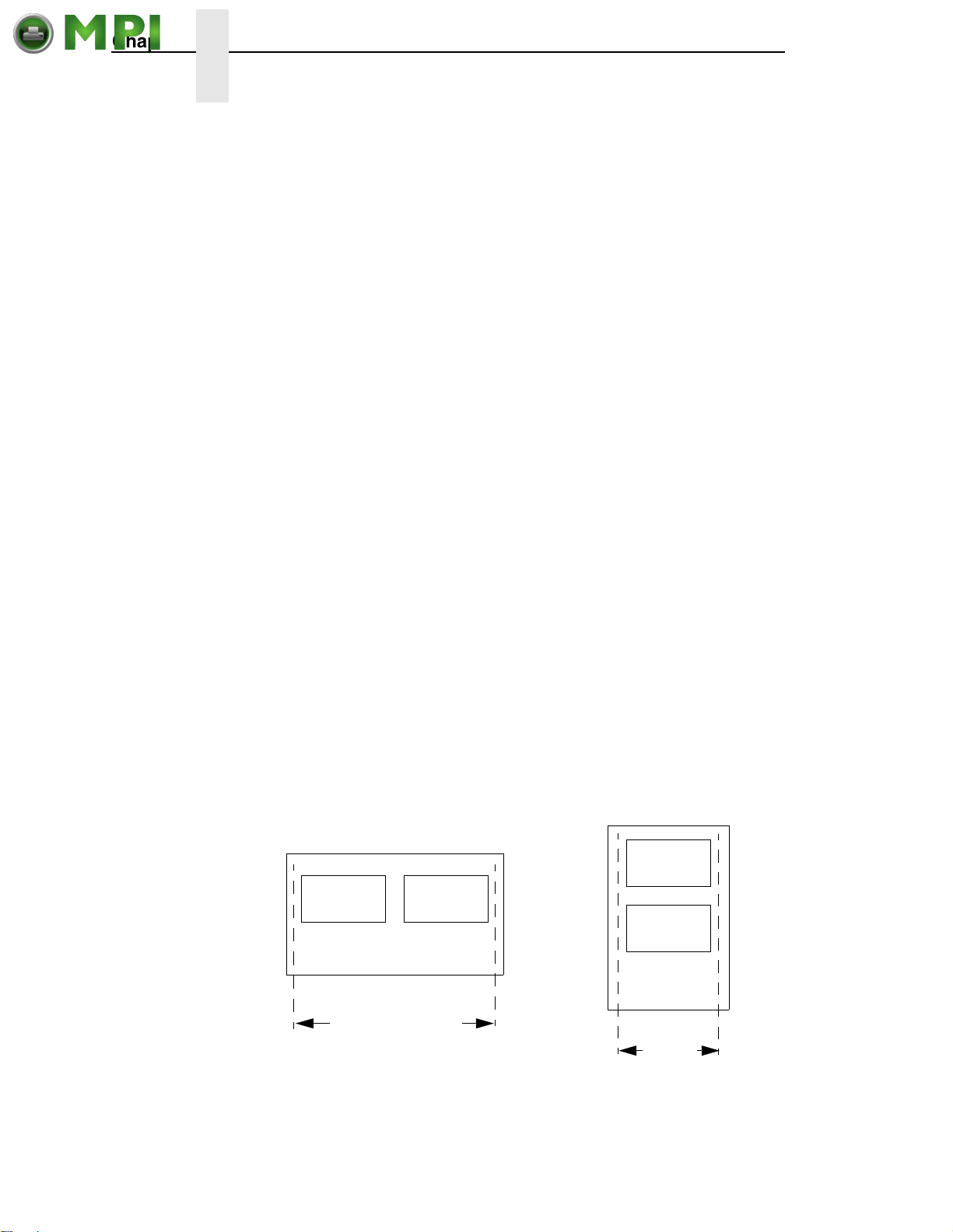
Chapter 4 MEDIA SETUP Menu
Mantenimiento Periféricos Informáticos C/Canteras, 15 28860 Paracuellos de Jarama (Madrid) Tel: 00 34 917481604 Web: https://mpi.com.es/
Auto Map Select
This option specifies the maximum print width to be used by the application.
The IGP/Auto Label Mapping
programs written for Printronix P5000 and P7000 and InfoPrint 6400 and
6500 line matrix printers using the Printronix PGL graphics language. It allows
the printer to print two-up (or other multi-up) labels. Instead of printing multiple
labels across the printer, it prints the leftmost label and the rightmost label, so
the printout will be twice as long but half as wide.
When enabled, the printer will automatically reposition the horizontally
adjacent labels to a vertically adjacent position, or a combination of horizontal
and vertical positions based on the values selected under the Auto Label
Width and Num Auto Labels menu items.
When disabled, excess data in any program sent to the printer with
horizontally adjacent labels that exceed the physical page width of the printer
will be clipped or wrapped depending upon the setting of the Autowrap menu
option.
The options are Disable (the factory default) and Enable.
Examples
All of the examples below assume that the logical form length is set to the
label length.
Example 1: Simple Case
Problem: A file has been constructed with two horizontally adjacent 4” labels
for a printer with a physical width of 8”. The user now wants to use this file
with a printer that has a 4” physical width.
®
feature allows backward compatibility of
Solution: The user sets Auto Label Width to 4” (the width of the label),
configures the Num Auto Labels to 2, and enables the Auto Label Mapping
feature.
Printer Operation: The printer will print the first (leftmost) 4” label first. Once
the first label has been completed, the printer will print the second 4” label.
These labels will appear vertically adjacent on the form.
Thermal Printer Output
Line-Matrix Printer Output
Label 1
Label 1 Label 2
Label 2
Wide Web Width Narrow
Web
Width
78
Page 79
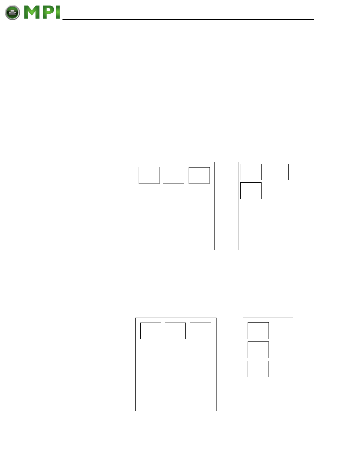
MEDIA SETUP Submenus
Mantenimiento Periféricos Informáticos C/Canteras, 15 28860 Paracuellos de Jarama (Madrid) Tel: 00 34 917481604 Web: https://mpi.com.es/
Example 2: Uneven Number Case
Problem: A file has been constructed with three horizontally adjacent 2”
labels. The user now desires to use this file with a printer that has a 4”
physical width.
Solution #1: The user sets
Auto Label Width
to 4” (the width of two labels),
configures the Num Auto Labels to 2, and enables the Auto Label Mapping
feature.
Printer Operation for Solution #1: The printer will print the first two labels at
the same time. These first two labels will be horizontally adjacent. Once these
labels have been completed, the printer will print the remaining 2” labels along
with a blank 2” label.
File Contents:
Label
1
Label2Label
3
Print Output:
Label
1
Label
3
Label
2
Blank
Label
Solution #2: The user sets
Auto Label Width
to 2”, configures the Num Auto
Labels to 3, and enables the Auto Label Mapping feature.
Printer Operation for Solution #2: The printer will print the first 2” label by
itself, the second 2” label by itself, and finally, the last 2” label by itself.
Label
1
Label
2
Label
3
Label
1
Label
2
Label
3
79
Page 80
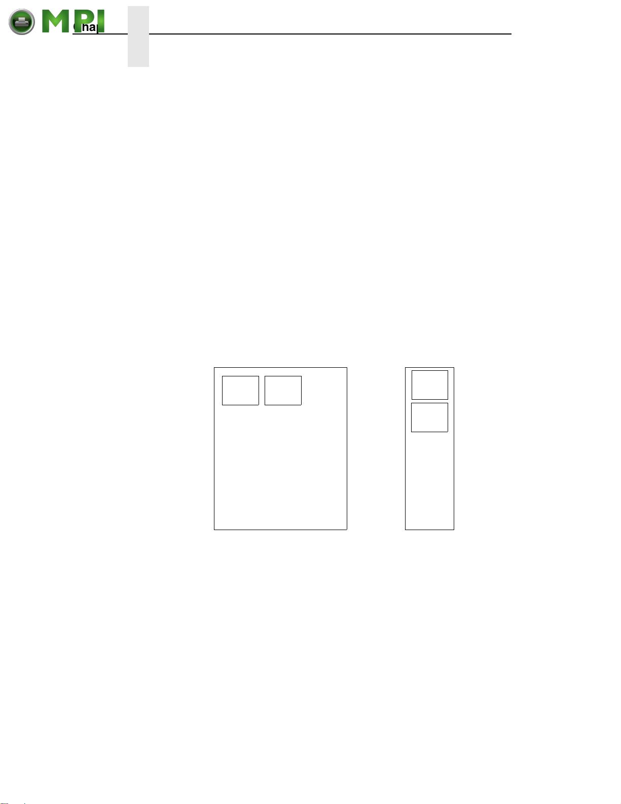
Chapter 4 MEDIA SETUP Menu
Mantenimiento Periféricos Informáticos C/Canteras, 15 28860 Paracuellos de Jarama (Madrid) Tel: 00 34 917481604 Web: https://mpi.com.es/
Example 3: Past Maximum File Width
Problem: A file has been constructed with three horizontally adjacent 4”
labels. The user now desires to use this file with a printer that has a 8”
physical width. The user should have used a solution similar to one of the
solutions in the section above, but the user erroneously enters an
Width
of 12” and a
Num Auto Labels
Auto Label
of 3.
Printer Operation:
to 2. The printer will automatically reduce the
Example 4: Blank Label Case
Problem: A file exists with two horizontally adjacent 4” labels. The user now
wants to use this file with a printer that has a 4” physical width. The user
decides to set the
that these values are not optimum.
Printer Operation: The maximum
selected value of 3 is legal. After the file is sent, the printer will begin by
printing the first 4” width label. Once that label is complete, it will print the
second 4” width label. Finally, once both of those labels have been printed,
the printer will print a blank 4” label.
File Contents:
Maximum Num Auto Labels = (20”/12”) = 1.67
Num Auto Labels
Num Labels
to 3 and the
Label Width
Num Auto Labels = (20”/4”) = 5
Print Output:
Label
1
Label
2
rounded up
to 2.
to 4” despite the fact
. The
Label
1
Label
2
Blank
Label
Auto Label Width
The width of a single label to be printed or the maximum width of the media
that will be used for the print file. The value is selectable from 00.1 inch
through the maximum print width of the printer.
NOTE: The maximum Auto Label Width value will be limited to the current
MEDIA CONTROL/Label Width value selected in the configuration
menu.
The default value depends on model width and size of DRAM installed.
80
Page 81
MEDIA SETUP Submenus
Mantenimiento Periféricos Informáticos C/Canteras, 15 28860 Paracuellos de Jarama (Madrid) Tel: 00 34 917481604 Web: https://mpi.com.es/
Num Auto Labels
The desired number of labels to be printed vertically adjacent on the form.
The value is selectable with a range of 1 through 40 labels.
The factory default is 2.
Slew Speed Ctrl
The speed at which the printer moves media without actually printing on it.
• Automatic (factory default). Always the same as the print speed.
• Manual. Allows you to set the slew speed. The maximum speed depends
on your printer model (see
Print Direction
This option determines the basic print image orientation.
NOTE: Print Direction will not change the orientation of any print test patterns
in the DIAGNOSTIC menu.
Print Direction has two options:
Table 17 on page 213).
• Head First
• Foot First
For example, with Portrait orientation, when you select Head First, the top-ofform will come out of the printer first. Conversely, when you select Foot First,
the bottom-of-form will come out first.
FEED
A
Head First
Figure 28. This Illustration Shows Both Head First and Foot First Print Direction
A
Foot First
81
Page 82
Chapter 4 MEDIA SETUP Menu
Mantenimiento Periféricos Informáticos C/Canteras, 15 28860 Paracuellos de Jarama (Madrid) Tel: 00 34 917481604 Web: https://mpi.com.es/
Print Direction and Orientation are two independent options that can be
combined to produce the following results depending on the Active IGP
Emulation:
Table 9. Results of Using the Head First Print Direction with Different
Orientation Options
Print Direction
Option
Head First Portrait Portrait
Head First Landscape Landscape
Head First Inv. Portrait Inv. Portrait
Head First Inv. Landscape Inv. Landscape
Orientation Option
Result in Active IGP Emulations
(PGL)
Table 10. Results of Using the Foot First Print Direction with Different
Orientation Options
Print Direction
Option
Foot First Portrait Portrait
Foot First Landscape Inv. Landscape
Foot First Inv. Portrait Inv. Portrait
Foot First Inv. Landscape Landscape
Orientation Option Result in Active ZGL Emulation
The factory default is Head First when PGL is enabled.
The factory default is Foot First when ZGL is enabled.
82
Label Wait Time
When Media Handling is set to Tear-Off Strip or when Media Handling is set
to Continuous and Continuous Mode is set to Tear Strip Full, Label Wait Time
specifies the number of seconds after the buffer is empty that the printer will
wait before it advances media to the tear bar position.
When Media Handling is set to Peel-Off, Label Wait Time specifies the
number of seconds the printer will wait after a label is removed from the peel
bar before starting to print the next label.
The range is 0.1 to 60.0 seconds, and the factory default is 0.1 second.
Page 83

MEDIA SETUP Submenus
Mantenimiento Periféricos Informáticos C/Canteras, 15 28860 Paracuellos de Jarama (Madrid) Tel: 00 34 917481604 Web: https://mpi.com.es/
Label Missing
If enabled, causes the Label Taken Sensor to first check for the presence of a
printed label at the tear bar for Peel Off and Tear Off Media Media Handling
Modes only.
• Fault Disable (factory default). The printer does not generate a fault
condition if a missing label is encountered. The printer will continue
printing the next label.
• Fault Enable. The printer generates a fault condition if a missing label is
encountered.
Clip Page
This option determines how the printer handles images that are too large for
one physical page length when using gap or black mark media.
• Enable (factory default). When the user-selected page length is greater
than the physical page length, the printer clips the excess data to fit the
physical page. The excess data is lost. The media sensor constantly
looks for the gap, notch, hole, or black mark and when detected, uses it
as the Top-of-Form position for the next label and clips any remaining
data from the label being printed.
• Disable. When the user-selected page length (logical length) is greater
than the physical page length dictated by the gap, notch, hole, or black
mark on media, the printer continues to print the remaining excess data
onto the next physical page.
The media sensor looks for the gap, notch, hole, or black mark only after
the media has advanced the distance specified by the Label Length value
in the MEDIA SETUP menu or by the Host Forms Length value sent via
the software. Any gaps, notches, holes, or black marks that exist prior to
reaching the Label Length or Host Forms Length value are ignored.
When Clip Page is set to Disable, Mark and Gap media sensing reliability
can be improved and the sensor problems described below can be fixed:
• The image starts to print at an erroneous distance from the top-of-
form, especially towards the end of a roll where the media is severely
curled or scalloped.
• The image is incorrectly positioned as a result of the media sensor
triggering off of a dark, pre-printed image on the label or multiple gaps
within the label.
• The printer starts to print one label and then another all on the same
physical label, especially at the end of a roll where the media is
severely curled.
• An occasional blank label appears within a print job (in between
printed labels).
When Clip Page is set to Disable, the printer ignores any pre-printed dark
marks or multiple gaps on a label that could mistakenly be detected as
the next top-of-form position based on the specified Label Length value.
The Label Length option is in the MEDIA SETUP menu.
83
Page 84

Chapter 4 MEDIA SETUP Menu
Mantenimiento Periféricos Informáticos C/Canteras, 15 28860 Paracuellos de Jarama (Madrid) Tel: 00 34 917481604 Web: https://mpi.com.es/
NOTE: When Clip Page = Disable, the correct Label Length value must be
entered. If the value is too long, the printer will ignore the actual gap
or mark it needs to detect. When using Gap sensing, the Label
Length value is equal to the physical length of a die cut or removable
label. When using Mark sensing, the Label Length value is the
physical distance from the leading edge of one black mark to the
leading edge of the next black mark.
Fault Reprint
This option determines how the printer handles data that was printing when
an error occurred.
• Disable (factory default). The printer will not reprint the label that was
printing when the error condition occurred.
• Enable. The printer reprints the label that was printing when the error
condition occurred.
NOTE: When Fault Reprint is set to Enable and a RIBBON OUT condition
occurs, some labels may not reprint. This depends on the label
length, print speed selected, and the additional time it takes to detect
this condition. Be sure to verify that all labels were reprinted after a
RIBBON OUT condition by using the Ribbon Low indicator as
described on
page 84.
Ribbon Low
When enabled, and the ribbon remaining on the supply spindle is less than
1/8 full, the Attention indicator will flash, and "Ribbon Low" displays on the last
line of the LCD. A Ribbon Low warning will not prevent printing.
The options are Disable (factory default) and Enable.
Ribbon Low displays if Admin User is set to Enable in the PRINTER SETUP
menu.
Units
This item selects either millimeters or inches as the unit of measure.
The options are In Inches (factory default) and In Millimeters.
84
Page 85

MEDIA SETUP Submenus
Mantenimiento Periféricos Informáticos C/Canteras, 15 28860 Paracuellos de Jarama (Madrid) Tel: 00 34 917481604 Web: https://mpi.com.es/
Set Label Length
This feature selects whether the Sensed Distance value derived from an Auto
or Manual Calibrate will be used to set the Label Length value in the MEDIA
SETUP menu.
• Manual (factory default). The Sensed Distance value derived from an
Auto or Manual Calibrate will not override or change the Label Length
value.
• Automatic. When an Auto or Manual Calibrate is performed, the Sensed
Distance value derived from either calibrate will override and change the
Label Length value. If no Auto or Manual Calibrate is performed, the
current Label Length value will be used.
NOTE: When Set Label Length = Automatic and Gap/Mark Sensor = Gap,
the printer will subtract the Gap Length value (in the SENSOR
SETUP menu) from the Sensed Distance value obtained when the
Auto or Manual Calibrate was performed.
If you set the label length to Automatic, the Enable setting for Use
Label Length under the Sensor Setup menu will be ignored.
TOF Detect Fault
Allows selection of three different TOF (Top-of-Form) detection faults.
NOTE: The correct Label Length value, equal to the physical length of the
installed label, must be entered MEDIA SETUP menu.
• 3 Labels (factory default). The printer displays a Gap Not Detected fault
and stops printing when media has advanced a distance equal to three or
more times the Label Length value set in menu.
• 9 Labels
• 1 Label
85
Page 86

Chapter 4 MEDIA SETUP Menu
Mantenimiento Periféricos Informáticos C/Canteras, 15 28860 Paracuellos de Jarama (Madrid) Tel: 00 34 917481604 Web: https://mpi.com.es/
Ticket Save Mode
This option determines the action of the media for Continuous (std), Tear-Off,
Tear-Off Strip and Cut Media Handling Modes after the printer is first powered
up or after the printhead has been opened and then closed. When enabled,
this option eliminates wasting label(s) or ticket stock when the printer
advances media to search for the next TOF position.
• Enable. The printer will assume that media is at the TOF position after
cycling power or after the printhead is opened and then closed. When a
print job is sent it is printed without advancing media to search for the next
TOF position.
NOTE: The user must ensure that media is at the correct TOF position (cross
perforation, liner gap, notch or mark at the tear bar edge) before
cycling power or before closing and locking the pivoting deck. In
addition, media must be calibrated and the correct Media Handling
Mode, Label Length and Gap/Mark Sensor selected and saved as the
Power-Up Config. Option applies to 3.75 inch or longer label lengths
only.
• Disable (factory default). The printer assumes that the media is not at the
correct TOF position after cycling power or after the printhead is opened
and then closed and advances media until the next gap, notch or mark is
detected by the Media Sensor(s). When print data is sent, printing begins
only after the next TOF is detected, resulting in one or more blank labels
being advanced.
NOTE: When set to Enable, Online Auto-Cal and Head-Auto-Cal will
automatically be set to Disable. The printer will not reset any settings
to Enable when Ticket Save Mode is later disabled.
TOF Adjust Mode
• Disable (factory default). This option disables the “TOF Adjust” distance
set using the TOF Adjust menu (see TOF Adjust below).
• Enable. This option enables the “TOF Adjust” distance set using the TOF
Adjust menu (see TOF Adjust below).
TOF Adjust
This opton sets the distance from the Top Of Form (TOF) that is left blank
(unprinted) after a label has been removed in Tear-Off Strip. Normally printing
is done starting at TOF, but when this mode is enabled the start position for
printing can be adjusted from 0.00 to 0.40 inches from TOF (in increments of
0.01 inch). This adjustment can be helpful if a die cut label sticks to the platen
by means of jagged edges created during removal of a poorly die cut label
when using the tear bar. By controlling how much blank space there is from
TOF, you can control how much the media is called back after it is torn off.
86
Page 87
SENSOR SETUP Menu
Mantenimiento Periféricos Informáticos C/Canteras, 15 28860 Paracuellos de Jarama (Madrid) Tel: 00 34 917481604 Web: https://mpi.com.es/
SENSOR
SETUP
(from page 69)
Gap/Mark
Sensor
Gap*
Disable
Mark
Paper Out
Thresh
000 to 255
Gap Length
0.12 inches*
0.05 to 1.00 inches
Notes:
* = Factory Default
Italicized items are available only when you enable Admin User (in the PRINTER SETUP menu).
1
The value depends on the sensor settings and calibration results.
2
If Gap/Mark Sensor (in the SENSOR SETUP menu) is set for Gap or Disable sensing, the factory default is 190.
If Gap/Mark Sensor is set for Mark, the factory default is 150.
3
You can change the unit value to millimeters. Set Units submenu to “In Millimeters” (in the MEDIA SETUP menu).
4
The value range varies depending on calibration results.
5
This option applies only when Gap/Mark Sensor is set to Mark.
Run Auto-Cal Run Profile
2
Run Manual
Cal
Cal in Peel
Mode
Disable*
4
Enable
Pwr Up
Action
Auto-Cal*
Seek TOF
Disable
Min Calib
20*
012 to 050
Sensed
Distance
0.00 inches*
0.01 inches to xx inches
Auto-Cal
Enable*
Disable
Delta
Head
Use Label
Disable*
Enable
3
Length
4
Online
Auto-Cal
Disable*
Enable
50%*
5% to 95%
Gap/Mark
Thresh
000 to 255
Threshold
Range
4
1
Gap
Windowing
Disable*
Enable
Mark TOF
Mark Trail Edge*
Mark Lead Edge
Detect
5
87
Page 88

Chapter 4 SENSOR SETUP Menu
Mantenimiento Periféricos Informáticos C/Canteras, 15 28860 Paracuellos de Jarama (Madrid) Tel: 00 34 917481604 Web: https://mpi.com.es/
SENSOR SETUP Submenus
Gap/Mark Sensor
The available options specify the sensor type needed for detecting the
Top-of-Form position on media with label length indicators (gaps, notches,
holes, or black marks).
• Gap (factory default). Select
between die-cut labels or when using tag stock with holes as label length
indicators on white background media. The Top-of-Form position is the
leading edge of the die cut label (trailing edge of the gap, notch, or hole).
when using media with a liner space
• Disable. Select when using media with no label length indicators
(no gaps, notches, holes, or black marks), or when you want the printer to
ignore all existing label length indicators on the installed media.
NOTE: When you select Disable, the length of each label is based on the
Label Length value entered in the MEDIA SETUP menu or the value
sent via host software.
• Mark. Select when using media that has horizontal black marks or
inbound notches located on the underside of the label liner or tag stock.
The Top-of-Form position is the trailing edge of the black mark.
The Top-of-Form depends on the Mark TOF Detect menu.
Run Auto-Cal (Auto-Calibrate)
This feature is used to set the sensitivity and reliability of the Media Sensor in
detecting gaps, notches, holes, or black marks on the installed media, as well
as a paper out condition.
Press the ↵ key with “Run Auto-Cal” displayed. The printer will then advance
media the distance needed to accurately detect the label length indicators,
then stop at the Top-of-Form position and momentarily display the Sensed
Distance. The process takes a few seconds to complete. The end result will
be a change to the Gap/Mark Threshold, Paper Out Threshold, and Sensed
Distance values that the printer will use. The changes in values take effect
immediately within the current configuration menu.
Run Auto-Cal is completed successfully when the Sensed Distance displayed
correctly matches that of the installed media. When Gap is selected, the
Sensed Distance should match the length from the trailing edge of one gap to
the trailing edge of the next gap (one label + one gap). When Mark is
selected, the Sensed Distance should match the length from the trailing edge
of one black mark to the trailing edge of the next black mark.
Run Auto-Cal supports label lengths up to 35 inches for Gap or Mark sensing
when Use Label Length is set to Disable.
88
Page 89

SENSOR SETUP Submenus
Mantenimiento Periféricos Informáticos C/Canteras, 15 28860 Paracuellos de Jarama (Madrid) Tel: 00 34 917481604 Web: https://mpi.com.es/
Run Profile
This feature provides a graphical printout showing the relationship of the
Paper Out Threshold and the Gap/Mark Threshold. The profile printout
assists you in setting the thresholds for difficult media. This includes
preprinted labels, and labels with poor gap/media dynamic range.
When selected, the printer will advance media and print the media profile
along the length of each label. The printer will continue to print the profile until
you press ↵.
Sensed Distance
This value (in inches) represents the distance that was sensed between the
TOF of one label to the TOF of the next label. With gapped media installed,
the distance equals the physical label length plus one gap, notch, or hole
(trailing edge of one gap, notch, or hole to the trailing edge of the next gap,
notch, or hole). With black mark media installed, the distance equals the
trailing edge of one black mark to the trailing edge of the next. This value is
automatically determined only after successful completion of Auto or Manual
Calibrate and cannot be changed manually.
The factory default is 0.00 inches.
Gap/Mark Thresh
This menu item sets a value that, when exceeded by the output of the media
sensor, is recognized by the printer as a gap (or black mark). When Auto or
Manual Paper Calibrate is performed, the value displayed is equal to the
gap/mark threshold value set by this procedure. If running the procedure does
not provide a reliable Top-Of-Form detection, e.g., when using unusual
media, the Gap/Mark Thresh value can be manually set to the desired value.
The range is 000 to 255. The factory default value depends on the calibration
results.
NOTE: If Gap/Mark Sensor (in SENSOR SETUP menu) is set for Gap
sensing, the factory default is 140. If Gap/Mark Sensor is set for
Mark, the factory default is 75.
Paper Out Thresh
This menu item selects a value that, when exceeded by the output of the
media sensor, is recognized by the printer as a paper out condition. When
Auto or Manual Calibrate is performed, the value displayed is equal to the
paper out threshold value set by this procedure. If running the procedure does
not provide a reliable paper out detection, e.g., when using non-standard
media, the Paper Out Thresh value can be manually set to the desired value.
The range is 000 to 255. The factory default value depends on the calibration
results.
NOTE: If Gap/Mark Sensor (in SENSOR SETUP menu) is set for Gap or
Disable sensing, the factory default is 190. If Gap/Mark Sensor is set
for Mark, the factory default is 150.
89
Page 90

Chapter 4 SENSOR SETUP Menu
Mantenimiento Periféricos Informáticos C/Canteras, 15 28860 Paracuellos de Jarama (Madrid) Tel: 00 34 917481604 Web: https://mpi.com.es/
Run Manual Cal
Run Manual Cal is another method of improving the printer’s media sensing
and is only used when Auto Calibrate has failed or the Gap/Mark Threshold or
Paper Out Threshold values derived from Auto Calibrate do not improve the
media sensors’ gap or mark sensing capability.
To initiate Run Manual Cal, press ↵ when “Run Manual Cal” displays under
the SENSOR SETUP menu. You will then be prompted for the remaining
steps.
Example: “REMOVE MEDIA/Press Enter”
NOTE: When requested to load an item make sure to place the item in a
position where the media sensor can detect the item. For example,
when requested to “LOAD MARK” place the Mark (Black TOF Line) at
the media sensor.
During the last stage of Run Manual Cal, the printer uses the statically derived
values, advances media, stops at the Top-of-Form position, and momentarily
displays the Sensed Distance. This process takes longer than Auto Calibrate,
and the end result is a change to the Gap/Mark Threshold, Paper Out
Threshold, and Sensed Distance values that the printer will use. These value
changes take effect immediately within the current configuration menu.
Run Manual Cal is completed successfully when the displayed Sensed
Distance correctly matches that of the installed media. When Gap is selected,
the Sensed Distance should match the length from the trailing edge of one
gap to the trailing edge of the next gap (or one label + one gap). When Mark is
selected, the Sensed Distance should match the length from the leading edge
of one black mark to the leading edge of the next black mark.
Run Auto-Cal supports label lengths up to 35 inches for Gap or Mark sensing
when Use Label Length is set to Disable.
Pwr Up Action
• Auto-Cal (factory default). When the printer is first powered on, it will
complete its initialization and self-tests and then perform an Auto
Calibrate. Once the Auto Calibrate is complete, the printer will
momentarily display the Sensed Distance determined by the Auto
Calibrate.
NOTE: If the printer is in Peel mode a calibration will not be done unless “Cal
in Peel Mode” is set to enable.
• Seek TOF. Moves the media to TOF at power up provided that the user
has already calibrated media using gap/mark sensor. A seek to TOF will
not be done if Gap/Mark Sensor is set to Disable or Ticket Save Mode is
set to Enable.
• Disable. No movement at power up.
90
Page 91

SENSOR SETUP Submenus
Mantenimiento Periféricos Informáticos C/Canteras, 15 28860 Paracuellos de Jarama (Madrid) Tel: 00 34 917481604 Web: https://mpi.com.es/
Head Auto-Cal
This option selects whether the printer does a media calibration after a
Printhead Open fault.
• Enable (factory default). Performs media calibration each time the
Printhead Open fault condition is cleared.
• Disable. No media calibration after Printhead Open fault.
NOTE: A calibration will not be done if there is print data pending (data in
buffer) when the head open fault is cleared, and Head Auto-Cal is
enabled. If the printer is in Peel mode, the calibration will not be done
unless “Cal in Peel Mode” is set to enable.
Online Auto-Cal
The options for Online Auto-Cal are:
• Disable (factory default).
• Enable. Whenever the printer is brought online, it automatically performs
an Run Auto-Cal (see
the Run Auto- Cal is complete, the printer momentarily displays the
Sensed Distance determined by the Auto Calibrate and then resumes
printing any pending jobs.
NOTE: A calibration will not be done when there is data in the buffer and
when Error Recover (in MEDIA SETUP menu) is enabled
(see page 71). If the printer is in Peel mode, the calibration will not be
done unless “Cal in Peel Mode” is set to enable.
“Run Auto-Cal (Auto-Calibrate)” on page 88). Once
Gap Windowing
This feature compensates for any early falling edges or spurious peaks and
troughs that may appear within the gap length in media. These edges or
peaks and troughs can cause unreliable detection of the leading edge of the
next label (top-of-form). Use Gap Windowing to resolve the following
problems:
• Loss of one or more complete (serialized) labels.
• Start of an image printed in the middle of a gap, especially with fanfold,
perforated media.
• Top part of an image lost when printing in head-first orientation.
The options for Gap Windowing are Disable and Enable:
• Disable (factory default). When the leading edge of a gap is detected, the
printer continuously looks for the leading edge of the next label and uses
it as the TOF position. Perforations or unusual media discrepancies within
the gap can cause inaccurate TOF detection.
91
Page 92

Chapter 4 SENSOR SETUP Menu
Mantenimiento Periféricos Informáticos C/Canteras, 15 28860 Paracuellos de Jarama (Madrid) Tel: 00 34 917481604 Web: https://mpi.com.es/
• Enable. When the leading edge of a gap is detected, the printer ignores
the first 90% of the gap length value specified in the Gap Length menu
option. The result is that cross perforations or unusual media
discrepancies within the gap are filtered out, allowing the printer to
reliably detect the actual leading edge of the next label and use it as the
TOF position.
NOTE: If Gap Windowing is enabled, the Gap Length menu must be set
correctly.
Gap Length
Gap Length is the actual length (height) of a label gap measured in .01 inch
increments. The range is 0.05 to 1.00 inches.
The factory default is 0.12 inches.
NOTE: If Gap Windowing is set to Enable, you must enter the correct Gap
Length. If the Gap Length is too long, the image will shift down from
the leading edge (TOF) of the label.
Cal in Peel Mode
This option allows you to perform a calibration (Run Auto-Cal or Pwr Up
Auto-Cal) in Peel-Off Media Handling mode.
• Disable (factory default). The printer will not permit calibration and a
“CANNOT CALIBRATE/Disable Peel-Off” message will briefly display.
Additionally, if “Pwr Up Auto-Cal” or “Head Auto-Cal” is enabled, the
printer will not perform calibration at power up or when the printhead is
closed.
• Enable. Run Auto-Cal can be performed from the front panel, and if the
Pwr Up Auto-Cal option is enabled, calibration will be performed at power
up.
NOTE: Calibration in Peel-Off mode does not stop and wait for you to remove
peeled labels. Therefore, be prepared to remove the labels as they
are automatically peeled.
Min Calib Delta
Minimum Calibrate Delta changes the minimum threshold value the sensor(s)
require to detect the difference between the label and a gap, notch, hole or
black mark. This allows bolder gaps (such as notches or holes) to be used as
the TOF while intermediate gaps (liner) can be ignored. Increasing the Min
Calib Delta makes the sensor(s) less sensitive to intermediate gaps and
noise. Decreasing the Min Calib Delta makes the sensor(s) more sensitive for
detecting gaps on low contrast media, where there is very little difference
between the label and the gap (liner).
The range is 012 - 050. The factory default is 20.
92
Page 93

SENSOR SETUP Submenus
Mantenimiento Periféricos Informáticos C/Canteras, 15 28860 Paracuellos de Jarama (Madrid) Tel: 00 34 917481604 Web: https://mpi.com.es/
Use Label Length
Determines whether or not the Label Length value set in the MEDIA SETUP
menu is used during Run Auto-Cal.
• Disable (factory default). Run Auto-Cal relies exclusively in its ability to
detect varying transitions between labels and gaps, notches, holes, or
black marks while advancing media during the calibrate process to
determine Sensed Distance. The amount of media advanced is based on
the number of transitions detected.
NOTE: Although the “Use Label Length” keeps its value (enable/disable) at
all times, it will always be disabled when “Set Label Length” is set to
“Automatic”. The correct setting will take effect when “Set Label
Length” is set to manual. Based on the setting on the “Set Label
Length” menu in the Media Setup menu, the “Use Label Length”
menu will be ignored (disabled).
• Enable. The Label Length value set in the MEDIA SETUP menu is used
in the calibrate algorithm. This causes the Run Auto-Cal process to
advance media the minimum distance required to detect the true gap,
notch, hole, or black mark used for TOF (Top-of-Form) sensing. This
resolves problems where the sensor(s) may mistake high noise levels or
preprinted images within the label as the gap, notch, hole, or black mark
that could result in a sensed distance value much shorter than the actual
label length. Example: A 0.2 inch calibrated Sensed Distance with a 3.0
inch long label installed.
NOTE: Setting the Label Length value less than half the actual length of the
label in use will result in erroneous Sensed Distance values when
Run Auto-Cal is performed.
Threshold Range
This option allows the user to select the optimal threshold range for the label
stock in use. The printer defaults to using a threshold range of 50% of the
positive going pulse (see Media Profile) that represents each gap, notch or
mark detected after doing an Auto or Manual Calibrate. The printer then
detects anything within the label with that threshold range as TOF. While this
range is ideal for most medias, some labels with a preprinted image, liner gap
or inlay can confuse the media sensor(s) causing a false TOF detection. In
most cases this can be resolved by selecting a higher threshold range so the
printer will only trigger on the true TOF (gap, notch or mark) position.
The range is: 5% to 95% in 5% increments
The factory default is 50%.
NOTE: Set the label length value in the Media Setup menu to the actual
length of the installed labels. A new threshold range will not take
affect until an Auto or Manual Calibrate is successfully performed.
A Media Profile should be run after a Calibrate to visually verify that
the new range is the best possible selection.
93
Page 94

Chapter 4 EMULATION MENU
Mantenimiento Periféricos Informáticos C/Canteras, 15 28860 Paracuellos de Jarama (Madrid) Tel: 00 34 917481604 Web: https://mpi.com.es/
Mark TOF Detect
Allows the user to select which edge of the black line is used for TOF (Top Of
Form). The leading edge refers to the first edge seen by the media sensor as
the media feeds out of the printer or the start of the black line.
• Mark Trail Edge (factory default). Trailing edge or end of black line
denotes TOF.
• Mark Lead Edge. Leading edge or start of black line denotes TOF.
NOTE: This option applies only when Gap/Mark Sensor is set to Mark.
EMULATION MENU
Overview
This section covers the following emulations:
• PGL (page 96)
IMPORTANT
• ZGL Config. (Refer to the
• TGL Config. (Refer to the
• IGL Config. (Refer to the
• STGL Config. (Refer to the
• DGL Config. (Refer to the
• MGL Config. (Refer to the
• IEGL Config. (Refer to the
You can select emulation default parameters directly from the control panel, or
by control codes as explained in the appropriate Programmer's Reference
Manual.
BEFORE you reconfigure an emulation, print a configuration sheet to
see all current settings.
ZGL Programmer’s Reference Manual.
TGL Programmer’s Reference Manual.
IGL Programmer’s Reference Manual.)
STGL Programmer’s Reference Manual.)
DGL Programmer’s Reference Manual.)
MGL Programmer’s Reference Manual
IEGL Programmer’s Reference Manual.
)
)
.)
)
PGL
The PGL emulation is the software based Printronix Graphics Language
(PGL) for the Printronix thermal printer family. It is based upon, and
compatible with, the IGP-100/200/400 board. It includes the following
features:
On-Line Form and Label Generation makes it easy to create forms or labels
with a “preprinted” look for each application. PGL programs control all graphic
functions, dramatically reducing host computer programming and processing
time.
Graphic capabilities include boxes, vertical and horizontal lines with userselectable thickness, logos, and special alphanumeric print features. Forms
and graphic designs can be duplicated horizontally and vertically.
94
Page 95

Alphanumeric data can appear as prepositioned “fixed” information (entered
Mantenimiento Periféricos Informáticos C/Canteras, 15 28860 Paracuellos de Jarama (Madrid) Tel: 00 34 917481604 Web: https://mpi.com.es/
when the form is created), be overlayed onto the form (positioned in a specific
location after the form is created), or may be dynamically merged with the
form.
Selectable Bar Codes provide you with the appropriate bar code for your
application using standard wide-to-narrow ratios. A wide selection of bar
codes are available: Australian 4-State, Codabar, Code 39, Code 128 Subset
A, B, and C, Data Matrix, EAN 8, EAN 13, FIM, Interleaved 2 of 5,
German I 2/5, Intelligent Mail, ITF 14, Matrix, Maxicode, MSI A through D,
PDF-417, Planet, Plessey, POSTNET, PostBar, Royal Mail, UCC/EAN-128,
UPC-A, UPC-E, UPCSHIP, and UPS 11. UPC and EAN bar codes can also
specify add-on data. Refer to the IGP
®
/PGL® Programmer’s Reference
Manual for more information.
Expanded and Compressed Character Print attract attention where
needed. Alphanumeric height and width are controlled independently for a
wide range of character sizes up to 113 times the standard character size (up
to 11.3 inches wide and tall). Compressed print sizes of 12, 13, 15, and 17
characters per inch (cpi) are available.
Logos are created using alphanumeric commands and add many print and
shading features for a “customized” appearance to forms, reports, and labels.
Rotated Alphanumerics permit new concepts in form design. Normal,
expanded, and compressed character strings can be rotated 90 degrees
clockwise or counterclockwise, or they can be printed upside down.
Reversed Print permits highlighting and contrasting by printing white
characters on a dark background.
Automatic Increment/Decrement Capability allows batch form processing.
You can identify individual numeric and bar code data fields, which includes
automatic increment or decrement functions.
Scaling Capability permits graphic elements, such as corners or boxes, to
retain their physical shapes and sizes when printed in a horizontal and vertical
density other than the base density of 60 x 72 dpi.
Multinational Character Sets provide 32 international character sets, each
96 characters in length. This feature also allows you to create your own
character sets using characters defined and stored in memory.
Extended Character Sets provide the user additional character sets besides
the 32 international character sets. Use the ~ISET command to select
different character sets including UTF-8 as well as alternate character sets by
entering a two-byte string enclosed within single quotes.
95
Page 96
Chapter 4 EMULATION MENU
Mantenimiento Periféricos Informáticos C/Canteras, 15 28860 Paracuellos de Jarama (Madrid) Tel: 00 34 917481604 Web: https://mpi.com.es/
EMULATION
(from page 69)
Select Emulation
xxx
Diagnostics
2
PGL*
ZGL
TGL
IGL
STGL
DGL
MGL
PGL
Diagnostics
On*
Debug
Fault
1
xxx
Diagnostics
Disable*
Print
Debug Port
3
Off
Host
See page 97 or
refer to the PGL
Programmer’s
Reference
Manual
IGL
Setup
STGL
4
Setup
4
DGL
Setup
Setup
PGL
Setup
4
4
ZGL
Setup
4
Refer to the ZGL
Programmer’s
Reference Manual
IEGL
4
Setup
TGL
4
Setup
Refer to the TGL
Programmer’s
Reference Manual
MGL
4
Setup
96
Refer to the IGL
Programmer’s
Reference Manual
Refer to the STGL
Programmer’s
Reference Manual
Refer to the DGL
Programmer’s
Reference Manual
Refer to the IEGL
Programmer’s
Reference Manual
Refer to the MGL
Programmer’s
Reference Manual
Notes:
* = Factory Default
Italicized items are available only when you enable Admin User (in the PRINTER SETUP menu).
1
This menu appears only if PGL is selected in the Select submenu.
2
xxx is set to the active emulation (PGL, ZGL, TGL, IGL, STGL, DGL, or MGL).
3
xxx is set to the active emulation (ZGL, TGL, IGL, STGL, DGL, or MGL).
4
This menu appears only if the emulation is selected in the Select submenu.
Page 97
PGL
Mantenimiento Periféricos Informáticos C/Canteras, 15 28860 Paracuellos de Jarama (Madrid) Tel: 00 34 917481604 Web: https://mpi.com.es/
SETUP
(from page 94)
PGL Setup
Character
Group
See page 99
Autowrap
Disable*
Enable
Var Form
Type
Add Nothing*
Add;0
Add;X
0) ASCII*
1) German
2) Swedish
3) Danish
4) Norwegian
5) Finnish
6) English
7) Dutch
8) French
Disable*
Enable
Disable*
Enable
Standard
Sets
Auto
Uppercase
Optimized
Ratio
9) Spanish
10) Italian
11) Turkish
12) CP 437
13) CP 850
14-15) Reserved
16-23) Dwn Overlay
24-31) User Def.
Slash 0
Disable*
Enable
PI Slew
Range
16*
15
Select LPI
6*
1 to 1000
Select SFCC
126*
1 - 255
CR Edit
Disable*
Enable
Define CR
Code
CR = CR*
CR = CR + LF
Host Form
Length
Enable*
Var. Length
Var Dynamic Len
Disable
Skip
Cmd Prefix
Enable*
Disable
Define LF
LF = LF*
LF = CR + LF
Var Form
Adjust
00.0 inches*
00.1 inches to
03.0 inches
Ignore Text
Disable*
Enable
Code
Power on
IGP/PGL
Enable*
Disable
Do FF
at TOF
Enable*
Disable
Ext Execute
Copy
Disable*
Enable
IGP100
Compatbl.
Disable*
Enable
AI 00 Spaces
Disable*
Enable
Expanded
Scalable*
Block
Alt Block 1
Font
Select SO
Char
14*
0 to 255
Normal*
Block
Scalable
Size
Ignore
Mode
Disable*
Enable
Disable*
Auto Reject
Forms
Handling
0*
0 to 255
Select Char
LP+ Menu*
PGL Menu
Auto TOF
Notes:
* = Factory Default
Italicized items are available only when Admin User is set to
Enable (in the PRINTER SETUP menu).
PGL
Normal
97
Page 98
Chapter 4 EMULATION MENU
Mantenimiento Periféricos Informáticos C/Canteras, 15 28860 Paracuellos de Jarama (Madrid) Tel: 00 34 917481604 Web: https://mpi.com.es/
PGL SETUP
(continued
from page 97)
UPC
Descenders
Always*
Never
Only With PDF
Vertical
Adjust
0 Dots*
-20 to 20 dots
I-2/5
Selection
Leading Zero*
Trailing Space
X2 DPD
Modulo 7 CD
Boundary
Check
Enable*
Disable
C39
Compatbl.
Disable*
Enable
Repeat Form
Opt
Enable*
Disable
User-Def
Ratio
Enable*
Disable*
Enable
Notes:
* = Factory Default
Italicized items are available only when Admin User is set to
Enable (in the PRINTER SETUP menu).
Disable
Preparser
Lead
PDF Dist
0.10 Inches*
0.01 inches to
0.10 inches
Storage
Select
DISK = EMC*
DISK = PCB FLASH
Trunc
Dyn Data
Disable*
Enable
98
Page 99
Character
Mantenimiento Periféricos Informáticos C/Canteras, 15 28860 Paracuellos de Jarama (Madrid) Tel: 00 34 917481604 Web: https://mpi.com.es/
Group
(from page 97)
Standard
Sets*
0) ASCII*
1) German
2) Swedish
3) Danish
4) Norwegian
5) Finnish
6) English
7) Dutch
8) French
9) Spanish
10) Italian
11) Turkish
12) CP 437
13) CP 850
14-15) Reserved
16-23) Dwn Overlay
24-31) User Def.
Hebrew Sets
Arabic Sets Cyrillic Sets
ASMO 449*
ASMO 449+
ASMO 708
ASMO 708+
MS DOS CP710
MS DOS CP720
Sakr CP714
Aptec CP715
CP 786
IBM CP864
IBM CP1046
Arabic Lam One
Arabic Lam Two
Win. CP 1256
Farsi 1
Farsi 2
1098 Farsi 1285
Turkish Sets
Code Page 866*
Cyrillic CP 437
Cyrillic 113
Cyrillic 8859-5
ISO 915
Code Page 855
Cyrillic 7 Bit
Ukrainian
Bulgarian
Win. CP 1251
Latvian 866
CP 1048
UTF-8
European
Sets
Latin 2 8859-2*
Code Page 852
Mazovia
Kamenicky
Roman 8
PC-437 Slavic
Slavic 1250
Code Page 865
Code Page 860
Latin 1 8859-1
Latin 5 8859-9
Latin 9 8859-15
Polish POL1
Win. CP 1250
Win. CP 1252
Win. CP 1257
CP 858 EURO
Lith. CP 773
Serbo Croatic 1
Serbo Croatic 2
CP 774
CP 775
ISO 8859-4
1
Greek Sets
DEC 256 Greek*
ELOT 928 Greek
Greek 3
ABY Greek
ABG Greek
ELOT 927 Greek
Greek 851
Greek 437
Greek 8859-7
Win. CP 1253
Greek 813 EURO
Greek 869 EURO
Hebrew Old*
Hebrew New
Hebrew DEC
Latin-1 Hebrew
Win. CP 1255
Data Gen. Turk.*
DEC Turkish
IBM Turkish
Siemens Turkish
PTT Turkish
IBC Turkish
Bull Turkish
AS400 Turkish
Unisys Turkish
NCR Turkish
PST Turkish
UNIS-1 Turkish
Code Page 853
INFO Turkish
Win. CP 1254
Code Page 857
Azeri
Notes:
* = Factory Default.
1
UTF-8 can be used with any font to access all of the
characters available in that font. For a font with the full
Unicode set, the Andalé font is available for purchase,
see page 235.
To access the desired basic character set, use the Left
and Right keys. To select the set, press the ↵ key. After
you have selected the basic set, access the subset
selection menu by pressing the Down key. Once in the
subset menu, access the desired subset by pressing
the Left and Right keys and select it by pressing the
↵ key.
99
Page 100

Chapter 4 EMULATION MENU
Mantenimiento Periféricos Informáticos C/Canteras, 15 28860 Paracuellos de Jarama (Madrid) Tel: 00 34 917481604 Web: https://mpi.com.es/
EMULATION Submenus
Select
This function allows you to activate any resident emulation listed in the menu.
The factory default is PGL.
There are two methods for selecting the desired emulation:
• Select the emulation under the Select menu option and save it as
Power-up Config.
• Send a host command to switch the emulation automatically (see the
appropriate Programmer’s Reference Manual for details).
xxx Diagnostics
NOTE: xxx is set to the active emulation (PGL, ZGL, TGL, IGL, STGL, DGL,
MGL, or IEGL).
• PGL Diagnostics. This item sets the error reporting capability of the
printer for PGL forms as follows:
• On (factory default). Full error checking reported. Any element that
falls off the current page is reported as an error.
• Debug. Puts the printer in debug mode whenever a form is defined in
CREATE mode. Each line of the CREATE form will be printed along
with an error if one has occurred.
• Fault. Allows you to halt the printer if a PGL error occurs. If you select
this option, the PGL error prints on the paper, the message “IGP/PGL
Error” displays on the front panel, and the printer goes offline. You
must clear the error before the printer can resume normal operation.
• Off. There is no error checking. Graphic elements such as alpha, line,
barcodes, etc. will be clipped if they are beyond the page boundaries.
• Host. Returns error messages to the host computer.
• xxx Diagnostics
NOTE: xxx is set to the active emulation (ZGL, TGL, IGL, STGL, DGL, MGL,
or IEGL).
• Disable. Prints the best results and will not log errors.
• Print. Prints the labels with best results and prints the errors on a
separate label.
• Debug Port. Prints the label and sends the errors to the Debug port.
Emulation Setup
Options for setting up the emulations. The options are PGL Setup, ZGL
Setup, TGL Setup, STGL Setup, IGL Setup, DGL Setup, MGL Setup and
IEGL Setup. Refer to the appropriate
100
Programmer’s Reference Manual
.
 Loading...