

Page 1
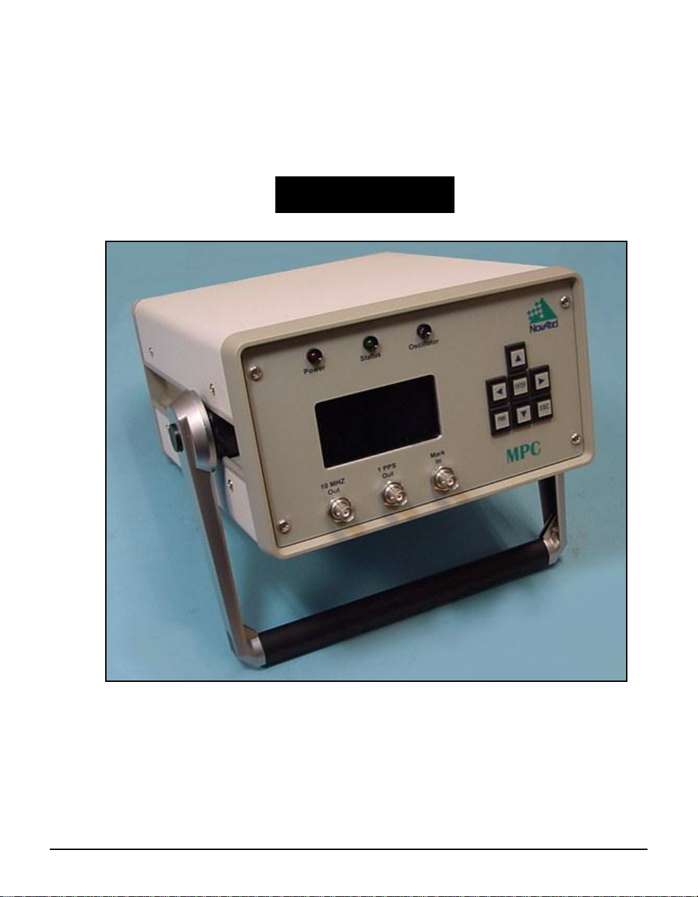
Modulated Precision
Clock (MPC)
USER MANUAL
OM-20000072 Rev 0D
Page 2

Proprietary Notice
Modulated Precision Clock (MPC) User Manual
Publication Number: OM-20000072
Revision Level: 0D
Revision Date: 2002/03/27
Proprietary Notice
Information in this document is subject to change without notice and does not represent a commitment
on the part of NovAtel Inc. The software described in this document is furnished under a licence
agreement or non-disclosure agreement. The software m ay b e us ed o r cop ied on ly in accordance with
the terms of the agreement. It is against the law to copy the software on any medium except as
specifically allowed in the license or non-disclosure agreement.
No part of this manual may be reproduced or transmitted in any form or by any means, electronic or
mechanical, including photocopying and recording, for any purpose without the express written
permission of a duly authorized representative of NovAtel Inc.
The information contained within this manual is believed to be true and correct at the time of
publication.
NovAtel, MiLLennium, RT-20 and RT-2 are registered trademarks of NovAtel Inc.
MPC, PAC, GPSCard and GPSAntenna are trademarks of NovAtel Inc.
All other brand names are trademarks of their respective holders.
© Copyright 2002 Novatel Inc. All rights reserved.
Unpublished rights reserved under International copyright laws.
Printed in Canada on recycled paper. Recyclable.
2 MPC User Manual Rev 0D
Page 3

Table of Contents
Proprietary Notice 2
Software License 8
Warranty Policy 9
Customer Servi ce 10
Notices 11
Foreword 12
Congratulations!.................................................................................................... 12
Scope.................................................................................................................... 12
Prerequisites......................................................................................................... 12
1 Introduction 13
1.1 Models and Features ....................................................................................... 14
1.2 Accessories and Options................................................................................. 15
2 Quick Start 16
3 MPC Setup Considerations 18
3.1 Choose the Right Antenna............................................................................... 18
3.2 Rear Panel Functionality.................................................................................. 19
3.2.1 10 MHz In and 10 MHz Out.................................................................... 20
3.2.2 DGPS ..................................................................................................... 20
3.2.3 Network I/O............................................................................................. 21
3.2.4 Power ..................................................................................................... 22
3.2.5 RF Port & Cables.................................................................................... 23
3.3 Front Panel Functionality................................................................................. 23
3.3.1 I/O Connectors and Cables.................................................................... 24
4 Using the MPC 25
4.1 Self-Test........................................................................................................... 25
4.2 Configuring the Network .................................................................................. 25
4.2.1 Ethernet Connect.................................................................................... 25
4.2.2 Modem or Direct Connect (PPP) Client.................................................. 26
4.3 Communication................................................................................................ 38
4.3.1 Logging Data .......................................................................................... 38
4.3.2 Differential GPS......................................................................................38
4.3.3 Errors...................................................................................................... 39
5 VFD Menus 40
5.1 Menu Access ................................................................................................... 41
5.1.1 Edit Digit Display .................................................................................... 41
5.1.2 Edit Group Display.................................................................................. 41
5.2 Menus .............................................................................................................. 42
5.2.1 Status ..................................................................................................... 42
MPC User Manual Rev 0D 3
Page 4

5.2.2 Connect...................................................................................................44
5.2.3 Configure Client ......................................................................................45
5.2.4 Configure Ethernet..................................................................................46
5.2.5 Configure Modem ...................................................................................47
5.2.6 Configure Direct (PPP) ...........................................................................48
6 Software Prog rams 49
6.1 Modulated Precision Clock Website.................................................................49
6.1.1 Logging ...................................................................................................50
6.1.2 Setup Configuration ................................................................................55
6.1.3 Analysis Plots..........................................................................................67
6.1.4 Download Data .......................................................................................72
6.2 MPC Firmware Upgrades & Updates...............................................................75
Appendices
A Technical Specifications 76
B GPS Overview 81
C WAAS Overview 95
D Replacement Parts 97
4 MPC User Manual Rev 0D
Page 5

Figures
1 MPC ............................ ............. ............. ............. ............. ............. ............. ...... 13
2 Typical MPC Setup .........................................................................................16
3 Close-up of Connectors on Rear Panel .......................................................... 19
4 10 MHz In/Out Data Flow ............................................................................... 20
5 MPC Front Panel ............................................................................................ 23
6 Modems Icon .................................................................................................. 26
7 Modems Properties ........................................................................................27
8 Install New Modem ......................................................................................... 27
9 Modem Installation Continued .............. ....... ...... ....... ...................................... 28
10 Modem Installation Finish ........ ....... ...... ....... ...... ....... ...... ....... ...... ...... ....... ...... 28
11 Installed Modem Properties ............................................................................ 29
12 Connection Properties .................................................................................... 29
13 Network Icon ................................................................................................... 30
14 Network Services ............................................................................................ 30
15 Select Network Service ..................................................................................31
16 Add RAS Device .............................................................................................31
17 Configure Port Usage ..................................................................................... 31
18 Network Configuration .................................................................................... 32
19 RAS Server TCP/IP Configuration ..................................................................32
20 Remote Access Setup ....................................... ....... ...... ....... ...... ...... .............33
21 Remote Access Admin Route ......................................................................... 33
22 Remote Access Admin on PC ........................................................................ 34
23 Start Remote Access Service .........................................................................34
24 Remote Access Admin ...... ...... ....... ...... ....... ...... ....... ...... ................................ 34
25 User Manager .................................................................................................35
26 New User ........................... ...... ....... ...... ....... ...... ....... ...... ....... ...... ...... ....... ...... 35
27 Dialin Information ............................................................................................ 36
28 Config Direct and Modem Menus ................................................................... 36
29 MPC Connect Menu ....................................................................................... 36
30 Loading Screen ..............................................................................................37
31 Website Password .......................................................................................... 37
32 CONFIG CLIENT Menu .................................................................................. 38
33 VFD Areas ............................................ ....... ...... ....... ...... ....... ...... ...... ....... ...... 40
34 Opening Menu ................................................................................................ 41
35 Edit Digit Mode ............................................................................................... 41
36 Edit Group Mode ............................................................................................ 42
37 STATUS Menus ................. ............................................. ................................ 42
38 MPC Connect Menu ....................................................................................... 44
39 Config Client Menus ... ....... ...... ....... ...... ....... ...... ....... ...... ....... ...... ...... ....... ...... 45
40 Config Ethernet Menu . ....... ...... ....... ...... ....... ...... ............................................. 46
41 Config Modem Menus .................... ...... ....... ...................................................47
42 Config Direct ...................... ...... ....... ...... ....... ...... ....... ...... ....... ...... ...... ....... ...... 48
43 Modulated Precision Clock Home Page ......................................................... 49
44 MPC Website Login ........................................................................................50
MPC User Manual Rev 0D 5
Page 6

45 Logging Control ...............................................................................................50
46 Set Up Logging ...............................................................................................51
47 Command/Response System Summary .........................................................53
48 Logging Statistics ............................................................................................55
49 Set Up Configuration .......................................................................................56
50 General Receiver Setup ..................................................................................56
51 Set Up E-Mail Server ......................................................................................57
52 Disk Maintenance ...........................................................................................58
53 Delete Files .................................... ....... ...... ....... .............................................58
54 Choose Files to Delete ....................................................................................59
55 Network Setup ................................................................................................59
56 Configure PPP Port .........................................................................................60
57 Configure Modem Port ....................................................................................61
58 Configure Ethernet Port ..................................................................................62
59 Receiver Setup ........... ...... ....... ...... ....... ...... ............................................. .......62
60 Current Receiver Configuration ......................................................................64
61 Reload Firmware .............................................................................................65
62 Set Up Users ...................................................................................................65
63 Edit User .........................................................................................................66
64 Add New User .................................................................................................66
65 Select Analysis Plot Type ...............................................................................67
66 Choose Value to Plot Against Time ................................................................68
67 Time Plot Example ..........................................................................................69
68 Time Plot Key ..................................................................................................69
69 Choose Sky Plot .............................................................................................69
70 Constellation Sky Plot .....................................................................................70
71 L1 Carrier to Noise Vs. Elevation ....................................................................71
72 L2 Code Minus Carrier Vs. Elevation ..............................................................71
73 Download Data ...............................................................................................72
74 GPS Calendar .................................................................................................72
75 Choose File to Download ................................................................................73
76 Typical File Download Window .......................................................................74
77 Save As ...........................................................................................................74
78 Power Cable ...................................................................................................80
79 NAVSTAR Satellite Orbit Arrangement ...........................................................81
80 Illustration of GPSCard Height Measurements ...............................................83
81 Accuracy versus Precision ..............................................................................84
82 Example of Differential Positioning .................................................................85
83 Single-Point Averaging ...................................................................................90
84 Typical Differential Configuration ....................................................................91
85 The WAAS Concept ........................................................................................96
6 MPC User Manual Rev OA
Page 7

Tables
1 MPC Controller Models ...................................................................................14
2 UDP Message Format..................................................................................... 52
3 MPC COM Port Pin-Outs ................................................................................79
4 Latency-Induced Extrapolation Error............................................................... 86
5 MPC Power Cable........................................................................................... 97
6 Accessories and Options................................................................................. 97
MPC User Manual Rev 0D 7
Page 8

Software License
Software License
BY OPENING THE SEALED DISK PACKAGE (ENVELOPE), YOU ARE AGREEING TO BE BOUND BY THE TERMS
OF THIS AGREEMENT. IF YOU DO NOT AGREE TO THE TE RMS OF THIS AG REEMENT, PROMPTLY RETURN
THE UNOPENED DISK PACKAGE AND THE ACCOMPANYING ITEMS TO NovAtel Inc.
1. License: NovAte l Inc. (“NovAtel”) grants you a non-exclusive license (not a sal e) to use one copy of the
enclosed NovAtel softw are on a single computer, and only with the product whos e model number and
serial number app ear on the envelope.
2. Copyright: NovAtel owns, or has the right to sublicense, all copyright, trade secret, patent and other
proprietary rights in the software and the software is protected by national copyright laws, international
treaty provisions and all other applicable national laws. You must treat the software like any other
copyrighted material except that you may either (a) make one copy of the software solely for backup or
archival purposes , or (b ) tr ansf er the s oftw are to a sing le hard d isk provided y ou kee p t he ori g inal sole ly
for backup or archival pu rposes. You may not copy th e product manual or written m aterials accompa nying
the software.
3. Restrictions: You may not: (1) copy (other than as provided for in paragraph 2), distribute, rent, lease or
sublicense all or any portion of the software; (2) mod if y or prepare derivative wo rks of the software; (3) use
the software in connection with computer-based services business or publicly display visual output of the
software; (4) tra nsmit th e software over a network , by telepho ne or elect ronically using a ny means; or (5)
reverse engineer, decompile or disa ssemble the s oftware. You agree to keep confident ial and use y our best
efforts to prev ent and protect the con tents of the software from unauthorized di sclosure or use.
4. Term and Termination: This Agreement is effective until terminated. You may terminate it at any time by
destroying the software, including all computer programs and documentation, and erasing any copies
residing on computer equ ipment. If you do so, you shoul d inform NovAtel in writing im mediately. This
Agreement also will terminate if you do not comply with any of its terms or conditions. Upon such
termination you are obl igat ed to de stroy th e so ftw are an d eras e all c opie s residing on co mput er equip men t.
NovAtel reserves the right to terminate this Agreement for reason of mi suse or abuse of this software.
5. Warranty: For 90 days from th e dat e of ship men t, Nov At el wa rran ts that th e me dia (f or exam ple , dis ke tte)
on which the software is contained will be free from defects in materials and workmanship. This warranty
does not cover damag e caused by improper use or negle ct. NovAtel does not warrant the contents of the
software or that it will be error free. The software is furnished "AS IS" and without warranty as to the
performance or results you may obtain by using the software. The entire risk as to the results and
performance of the software is assumed by you.
6. For software UPDATES and UPGRADES, and regular customer support, contact the NovAtel GPS Hotline
at 1-8
00-NOVATEL (U.S. or Canada only), or 403-295-4900, Fax 403-295-4901, e-mail to
NovAtel Inc.
Customer Service Dept.
1120 - 68 Avenue NE,
Calgary, Alberta, Canada T2E 8S5
7. Disclaimer of Warranty and Limitation of Liabi li t y:
a.THE WARRANTIES IN THIS AGREEMENT REPLACE ALL OTHER WARRANTIES, EXPRESS OR IMPLIED,
INCLUDING ANY WARRANTIES OF MERCHANTABILITY OR FITNESS FOR A PARTICULAR PURPOSE. NovAtel
DISCLAIMS AND EXCLUDES ALL OTHER WARRANTIES. IN NO EVENT WILL NovAtel’s LIABILITY OF ANY
KIND INCLUDE ANY SPECIAL, INCIDENTAL OR CONSEQUENTIAL DAMAGES, INCLUDING LOST PROFITS,
EVEN IF NovAtel HAS KNOWLEDGE OF THE POTENTIAL LOSS OR DAMAGE.
b.NovAtel will not be liable for any loss or damage caused by delay in furnishing the software or any other performance
under this Agreem ent.
c.NovAtel’s entire liabil ity a nd your exclusive remedies for ou r liability of any kind (in cl ud in g lia bi lity for negligence)
for the software covered by this Agree ment and all other perf or m ance or non-perfor m ance by NovAtel under or related
to this Agreement are to the remedies sp e cified by this Agreement.
This Agreement is governed by the laws of t he Province of Albert a, Canada. Each of the partie s hereto irrevocably
attorns to the jurisdiction of the courts of the Province of Alberta.
MPC User Manual Rev 0D 8
Page 9

Warranty Policy
Warranty Policy
NovAtel Inc. warrants that its Global Positioning System (GPS) products are free from defects in materials and
workmanship, subject to the conditions set forth below, for the following periods of time:
MPC Receiver One (1) Year
GPSAntenna™ Series One (1) Year
Cables and Accessories Ninety (90) Days
Software Support One (1) Year
Date of sale shall mean the date of the invoice to the original customer for the product. NovAtel’s responsibility
respecting this warranty is solely to product repl acement or p roduct rep air at an authori zed NovAt el location o nly.
Determination of replacement or repair will be made by NovAtel personnel or by technical personnel expressly
authorized by NovAtel for this purpose.
THE FOREGOING W ARRANTIES DO NOT EXTEND TO (I) NONCONFORMITIES, DEFECTS OR
ERRORS IN THE PRODUCTS DUE TO ACCIDENT, ABUSE, MISUSE OR NEGLIGENT USE OF
THE PRODUCTS OR USE IN OTHER THAN A NORMAL AND CUSTOMARY MANNER,
ENVIRONMENTAL CONDITIONS NOT CONFORMING TO NOVATEL’S SPECIFICATIONS, OR
FAILURE TO FOLLOW PRESCRIBED INSTALLATION, OPERATING AND MAINTENANCE
PROCEDURES, (II) DEFECTS, ERRORS OR NONCONFORMITIES IN THE PRODUCTS DUE TO
MODIFICATIONS, ALTERATIONS, ADDITIONS OR CHANGES NOT MADE IN ACCORDANCE
WITH NOVATEL’S SPECIFICATIONS OR AUTHORIZED BY NOVATEL, (III) NORMAL WEAR
AND TEAR, (IV) DAMAGE CAUSED BY FORCE OF NATURE OR ACT OF ANY THIRD PERSON,
(V) SHIPPING DAMAGE; OR (VI) SERVICE OR REPAIR OF PRODUCT BY THE DEALER
WITHOUT PRIOR WRITTEN CONSENT FROM NOVATEL. IN ADDITION, THE FOREGOING
WARRANTIES SHALL NOT APPLY TO PRODUCTS DESIGNATED BY NOVATEL AS BETA SITE
TEST SAMPLES, EXPERIMENTAL, DEVELOPMENTAL, PREPRODUCTION, SAMPLE,
INCOMPLETE OR OUT OF SPECIFICATIO N PRODUCTS OR TO RETURNED PRODUCTS IF
THE ORIGINAL IDENTIFICATION MARKS HAVE BEEN REMOVED OR ALTERED. THE
WARRANTIES AND REMEDIES ARE EXCLUSIVE AND ALL OTHER WARRANTIES, EXPRESS
OR IMPLIED, WRITTEN OR ORAL, INCLUDING THE IMPLIED WARRANTIES OF
MERCHANTABILITY OR FITNESS FOR ANY PARTICULAR PURPOSE ARE EXCLUDED.
NOVATEL SHALL NOT BE LIABLE FOR ANY LOSS, DAMAGE, EXPENSE, OR INJURY
ARISING DIRECTLY OR INDIRECTLY OUT OF THE PURCHASE, INSTALLATION,
OPERATION, USE OR LICENSING OR PRODUCTS OR SERVICES. IN NO EVENT SHALL
NOVATEL BE LIABLE FOR SPECIAL, INDIRECT, INCIDENTAL OR CONSEQUENTIAL
DAMAGES OF ANY KIND OR NATURE DUE TO ANY CAUSE.
There are no user serviceable parts in th e GPS recei ver and no maintenance is requir ed. When the status code
indicates that a unit is faulty, replace with another unit and return the faulty unit to NovAtel Inc.
Before shipping any material to NovAtel or Dealer, please obtain a Return Material Authorization (RMA)
number from the po int of purchase.
Once you have obtained an RMA number, you will be advised of pr oper shipping procedures to return any
defective product. When returning any product to NovAtel, please return the defective product in the original
packaging to avo id ESD an d shipping damage.
MPC User Manual Rev 0D 9
Page 10

Customer Service
Customer Service
EURO4 FIRMWARE UPDATES AND UPGRADES
Firmware updates are firmware revisions to an existing model, which improves basic functionality of
the GPS receiver. During the one-year warranty coverage following initial purchase, firmware updates
are supplied free of charge. After the warranty has expired, firmware updates and updated manuals
may be subject to a nominal charge.
Firmware upgrades are firmwar e releases, which increase basic functionality of the receiver from one
model to a higher level model type. When available, upgrades may be purchased at a price, which is
the difference between the two model types on the current NovAtel GPS Price List plus a nominal
service charge.
Please see Section 6.2, MPC Firmware Upgrades & Updates on page 75 for a description on how
your MPC is upgraded/updated via the web.
CONTACT INFORMATION
Firmware updates and upgrades are accomplished through NovAtel authorized dealers.
Contact your local NovAtel dealer first for more information. To locate a dealer in your area or if the
problem is not resolved, contact NovAtel Inc. directly using one of the following methods:
Call the NovAtel GPS Hotline at 1-800-NOV ATEL (Nor th America), or 403- 295-49 00 ( internati onal ).
Fax: 403-295-4901
E-mail: [email protected]
Website: http://www.novatel.com
Write: NovAtel Inc., Customer Service Dept., 1120 - 68 Avenue NE, Calgary, AB., Canada, T2E 8S5
* Before contacting NovAtel Customer Service regarding software concerns, please do the
following:
Install the MPC on the internet with a fixed IP address or phone number so that NovAtel
Customer Service can access it directly. Also, supply your IP address, or phone number, to
NovAtel Customer Service.
You may be requested to send Customer Service any *. log files that appear in your MPC’s ftp
site or your root directory.
MPC User Manual Rev 0D 10
Page 11

Notices
Notices
The following notices apply to MPC.
CSA NOTICE
Each MPC unit has been tested by a Canadian Standards Association (CSA) inspector and found to
comply with the special Inspection Requirements of Electrical Equipment. More specifically, this
equipment has been tested for Dielectric strength up to 1000 VAC. The supplied AC electric cord is
also approved and must be used with this equipment at all times. The primary fuse rating must be
strictly adhered to as labelled on the rear of the unit ne ar the fuse hol der . Each MPC unit must have t he
CSA approved label attached on the rear of the unit.
CAUTION!
1. This device incorporates circuitry to absorb most static discha rges. Howev er, seve re stat ic shock
may cause inaccurate operation of the unit. Use anti-static precautions where possible.
2. This device is a precision instrument. Although it is designed for rugged operating conditions, it
performs best when handled with care.
3. The MPC can accept an input supply voltage in the range 100 to 240 VAC. This may not be the
same range as other NovAtel products with which you are familiar. Operating the MPC below 100
VAC causes the unit to suspend operation. An input voltage above 240 VAC may physically
damage the unit.
4. Drawing more than the specified maximum current (1.5 amp) may cause the internal fuse to
interrupt the current. Restoring normal operation will require replacing the fuse.
MPC User Manual Rev 0D 11
Page 12

Foreword
Foreword
Congratulations!
Congratulations on your purchase of the Modulated Precision Clock (MPC).
NovAtel is an industry leader in state-of-the-art GPS receiver design. We believe that our MPC will
meet your high expectations, and are working hard to ensure that future products and enhancements
will maintain that level of satisfaction.
This is your primary hardware and software reference.
Scope
This manual contains sufficient information on the installation and operation of the MPC and its
software to allow you to effectively integrate and fully operate it. It is beyond the scope of this manual
to provide details on service or repair. Contact your local NovAtel dealer for any customer-service
related inquiries, see Customer Service on Page 10.
After the addition of accessories, an antenna and a power source, the MPC will be ready to go.
The MPC incorporates a Vacuum Fluorescent Display (VFD) on its front panel and this manual will
take you through its menus and features, see VFD Menus on Page 40. A VFD Menus Quick Look
weatherproof guide is als o pr ovided to help you find the V FD win dows yo u n eed i n a hur ry, using the
navigation buttons on the MPC.
The Euro4 in the MPC utilizes a comprehensive user-interface command structure, which requires
communications through its communications (COM) ports. A supplementary manual is included to
aid you in using the commands and logs available in the OEM4 family of receivers.
It is recommended that these documents be kept together for easy reference.
A graphical user interface is provided for your MPC via the internet, see Section 6.1, Modulated
Precision Clock Website on Page 49.
Prerequisites
A standard internet browser, e.g. Netscape or Microsoft Internet Explorer, is required on a PC work
station to access the Modulated Precision Clock website.
MPC User Manual Rev 0D 12
Page 13
Chapter 1 Introduction
The MPC is a high performance, high accuracy, GPS receiver with fast data update rates and
integrated memory in its hard disk for data logging. The MPC’s front panel also features a Vacuum
Fluorescent Display (VFD) panel and keypad for on the fly configurations.
Depending on which model you purchase, the MPC is capable of receiving and tracking the L1 C/A
code, L1 and L2 carrier phase and L2 P-Code (or encrypted Y-Code) of up to 12 satellites. Patented
Pulsed Aperture Correlator (PAC) technology combined with a powerful microprocessor make
possible multipath-resistant processing and excellent acquisition and re- acquisition times.
Once you connect the MPC to an antenna and power source, it begins operating as a fully functional
GPS system (see Chapter 2, Quick Start on Page 16 and Cha pt er 3, MPC Set up Con siderations on
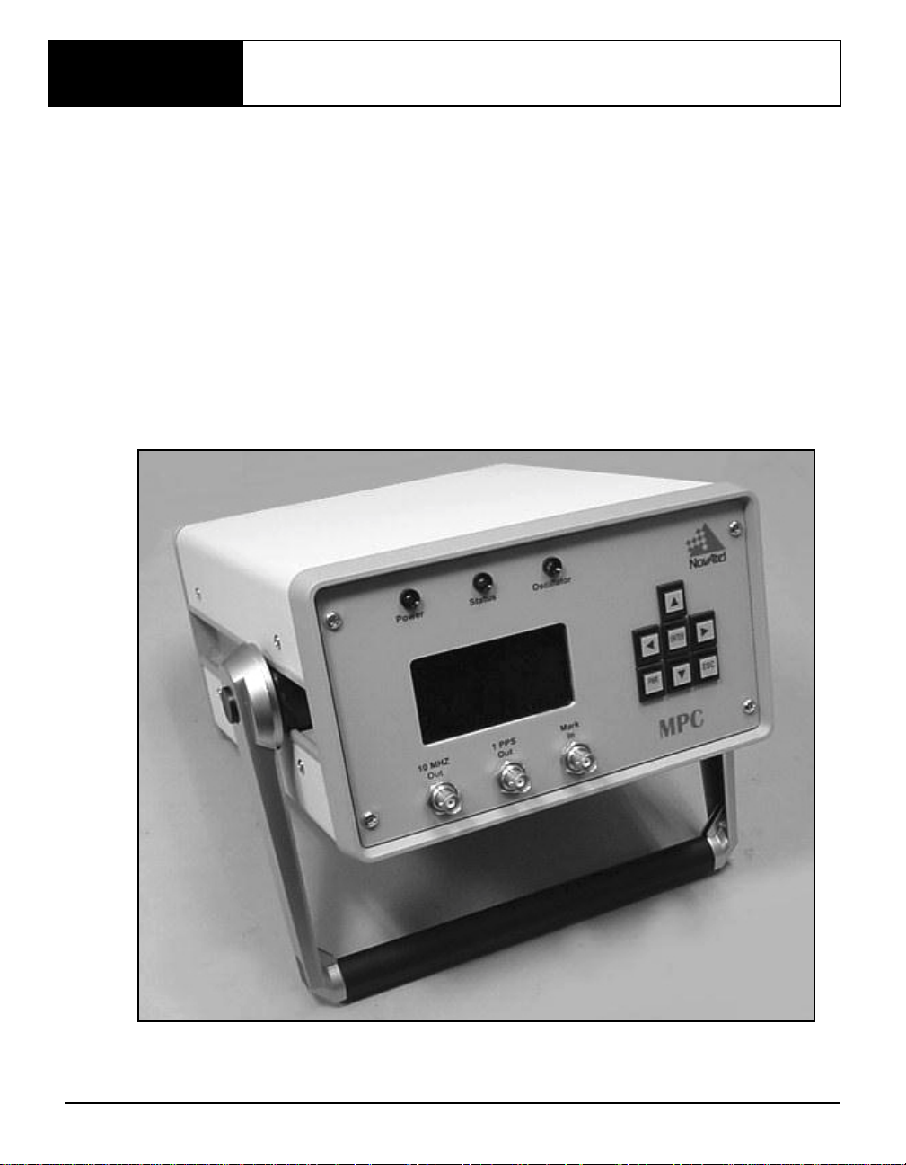
Page 18, for more information on this topic). Figur e 1 shows the MPC without an antenna or
connecting cables.
Figure 1: MPC
MPC User Manual Rev 0D 13
Page 14

Chapter 1 Introduction
1.1 Models and Features
The MPC is available in several different firmware models whose configurations may include other
additional features. Some possible configurations can be seen in Table 1.
Table 1: MPC Controller Models
Model Name Firmware Feature
MPC-L1
MPC-L1L2
MPC-L1L2W
a. Please see Appen dix C, WAAS Overview on
Page 95.
L1-only
L1/L2
L1/L2 with WAAS
a
All the above models are capable of multiple positioning modes of operation:
• Single point
• Pseudorange differential corrections
• Post-processed RTK-type accuracy
The MPC has a carrying handle that can be adjusted through 360 degr ees. To move the handles, press
in the buttons and turn in the direction you want the handles to go. Let go of the buttons and move the
handle slightly so as to lock it in place.
Each model has the following standard features:
• NovAtel's advanced OEM4 L1/L2 GPS technology in its Euro4 card
• Capability to log up to 19 GB of data on its hard disk
• Capability to execute scheduled logging on its hard disk
• Vacuum Fluorescent Display (VFD) panel and keypad for on the fly data information
and configurations
• 4 internet/intranet connect opt ions (ethernet, direct-PPP, modem client or modem host)
• 1 DGPS/RTK communications port for L1/L2 differential broadcasts
• Field-upgradeable fi rmware (program software). What makes one model different from
another is software, not hardware. This unique feature means that the firmware can be
updated anytime, anywhere, without any mechanical procedures w hatsoever. For
example, a model with L1/L2-only capabilities can be upgraded to a model with L1/L2
W AAS in only a few minutes at your installed location (instead of the days or weeks that
would be required if the receiver had to be sent to a service depot). All that is requir ed to
unlock the additional features is a special authorization code and internet, or intranet,
accessibility.
Please see Section 6.2, MPC Firmware Upgrades & Updates on page 75 for a
description on how your MPC is upgraded/updated via the web.
14 MPC User Manual Rev 0D
Page 15

Introduction Chapter 1
1.2 ACCESSORIES AND OPTIONS
The MPC can be used with the following accessories:
• Power cable to connect the MPC to a 110 or 220 VAC power source
• An optional choke ring is available for the 501 antenna (model A031)
• Optional NovAtel GPSAntenna Model 600 series - dual or single frequency, active
antennas designed for high-accuracy applications without the need for a choke ring
• Optional NovAtel Model C005, C015, or C030 coaxial antenna cable in 5 m (16.4’),
15 m (49.2’), or 30 m (98.4’) lengths
• Optional serial cables for compatibility with certain data communications devices to
the DGPS or PPP ports
• User-supplied RJ11 cable for the Modem port connector
• User-supplied RJ45 cable for the Ethernet port connector
Should you need to order an accessory or a replacement part, NovAtel part numbers are shown in
Appendix D on Page 97. Not all of the above accessories are available from NovAtel.
MPC User Manual Rev 0D 15
Page 16
Chapter 2 Quick Start
Setting up the MPC is a straightforward process, whether you are in the field (collect ing data ) or back
at the office (configuring the MPC, or transferring collected data to your PC for post-processing).
CAUTION!: See the cautions on Page 11 of the Notices for a list of items you should be aware
of as you set up and use the MPC.
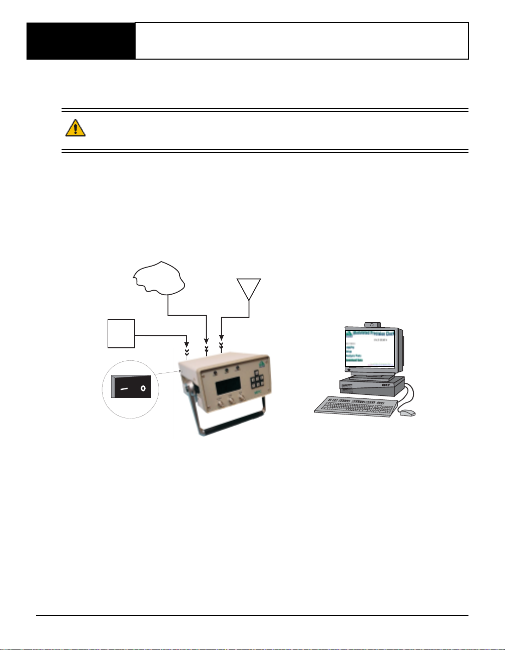
Figure 2 displays how you might typically set up the MPC at the office (for example, as a base to set
up other receivers in the grid, or to transfer collected data fro m other receivers to the bas e MPC, or as
a stand alone receiver). In these situations, the MPC is connected to the internet and ener gy is supplied
by means of a power source in the range 100 to 240 VAC. No matter what country the power source
comes from, the MPC will automatically recognise and accept the voltage.
Figure 2: Typical MPC Setup
6
9
7
2
3
8
4
5
10
11
1
Reference Description Reference Description
1 MPC 8 Modem (RJ11), Ethernet (RJ45)
2 Power source or PPP (RS232) connector
3 MPC power cable 9 GPS antenna
4 Input Power connector 10 GPS antenna cable
5 Close-up of on/off (-/o) switch 11 GPS Antenna In connector
6 Internet provider 12 User-supplied PC to view the
7 User-supplied RJ45 cable
to Ethernet, or RJ11cable to on the internet
Modem, or RS232 cable to
PPP connector
Modulated Precision Clock website
MPC User Manual Rev 0D 16
Page 17

Quick Start Chapter 2
A typical configuration would result from the following steps (see also Figure 2 on Page 16):
1. Place the MPC on a desk or other suitable work surface.
2. Connect the output of a power source to the Power Input port on the back of the MPC.
3. Connect a GPS antenna to the GPS Antenna In connector on the back of the MPC.
4. Connect an appropriate cable from the back of the MPC (PPP, Ethernet or Modem port) to
your intended internet or intranet connection source.
5. Press the power button.
6. Configure your intended i nternet con nection us ing the VFD menu s. The MPC su pports many
options for internet connectivity, please see Section 4.2, Configuring the Network starting on
Page 25 for details.
7. Monitor the MPC status using the VFD menus.
8. Obtain the MPC IP address given by your internet provider, as displayed by the VFD or
provided by your MPC Admini strator, to use as a URL to go to t he Modulated Pr ecision Clock
website for your MPC receiver using a PC. The following is a fictional example:
http://123.123.123.123/
* Your Network Administrator may wish to provide you with a “STATIC” IP location on your
internal network (intranet) and associate this IP address with a name, for example “MPC1”, in
your Domain Name Server (DNS). In this case, you would access your MPC’s web page via the
URL:
http://mpc1/
9. Browse to the Modulated Precision Clock website.
10. The Modulated Precision Clock website for your MPC now becomes your user interface
where you can set up logging, modify con figurat ions, view logging summaries and plots, and
download data.
The sections of Chapter 3, MPC Setup Considerations startin g on Page 18 give further details on
Steps #2 to #5, while Chapter 5, VFD Menus starting on Page 40 gives details on the menus in Steps
#6 & #7, Section 4.2, Configuring the Network starting on Page 25 helps with Step #6, and Modulated
Precision Clock Website on Page 49 is devoted to Steps #8 and #9.
* The MPC is designed for continuous operation. However, if you need to power down the unit, it
is recommended that you always use the MPC Shutdown Type menu, see Page 45. Then give the
internal operating system a few minutes to flush its cache buffers to the hard drive, and turn off
the power at the power switch.
MPC User Manual Rev 0D 17
Page 18

Chapter 3 MPC Setup Considerations
3.1 Choose the Right Antenna
The recommended antenna is from the GPS-600 antenna series, which are ideal for all applications. A
Model 600 GPSAntenna provides comparable performance to a choke ring ground plane antenna
while being much lighter and smaller.
When installing the antenna system,
• choose an antenna location that has a clear view of the sky so that each satellite above the
horizon can be tracked without obstruction.
• mount the antenna on a secure, stable structure capable of safe operation in the specific
environment.
The purpose of the GPS antenna is to convert the electromagnetic waves transmitted by the GPS
satellites into RF signals. An active GPS antenna is required for the MPC to function properly; there is
a provision to enable or disable the DC power to the active GPS antenna in case you wish to use an
antenna that has an alternate power source. Please refer to the ANTENNAPOWER command in
Volume 2 of the OEM4 Users’ Guide for details on the command to do this. See List Current
Configuration on Page 63 for information on how to issue commands via the Modulated Precision
Clock website.
An active antenna is required because its low-noise ampl ifier (LN A) boosts the power of the incoming
signal to compensate for the line loss between the antenna and the Euro4 GPSCard. If the limit of 14
dB of allowable cable loss is exceeded, excessive signal degradation will occur and the GPSCard may
not be able to meet its performance specifications.
NovAtel offers a variety of single and dual-frequency GPSAntenna models. All include band-pass
filtering and an LNA. The GPSAntenna you choose (models 501, 511, 521 and 531 are L1-only;
models 600, 502, 503 and 512 are dual-frequency GPSAntennas) will depend on your particular
application. Each of these models offer exceptional phase-center stability as well as a significant
measure of immunity against multipath interference. Each one has an environmentally-sealed radome.
NovAtel also offers high-quality coaxial cable in standard 5 (Model C005), 15 (Model C015) and 30
m (Model C030) lengths. These come with a TNC male connector at each end. Should your
application require the use of cable longer than 30 m you will find the application note Extended
Length Antenna Cable Runs at our website, http://www.novatel.com
NovAtel Customer Service directly; see the Customer Service Sect ion at the beginning of this manual.
High-quality coaxial cables should be used because a mismatch in imped ance, possible with lower
quality cable, produces reflections in the cable that increase signal loss.
While there may be other coaxial cables and antennas on the market which may also serve the
purpose, please note that the performance specifications of the MPC are warranted only when it is
used with NovAtel-supplied accessories
The Euro4 GPSCard is factory-configured for operation with any of the dual-frequency factory
configured GPSAntenna models, in which case no special wiring is required. The internal antenna
power sourc e of the Euro4 can produce +4.25 to +5.25 V DC at up to 90 mA.
MPC User Manual Rev 0D 18
, or you may obtain it from
Page 19
MPC Setup Considerations Chapter 3
CAUTION
No warranty is made that the MPC will meet its performance specifications if a non-NovAtel antenna
is used.
3.2 Rear Panel Functionality
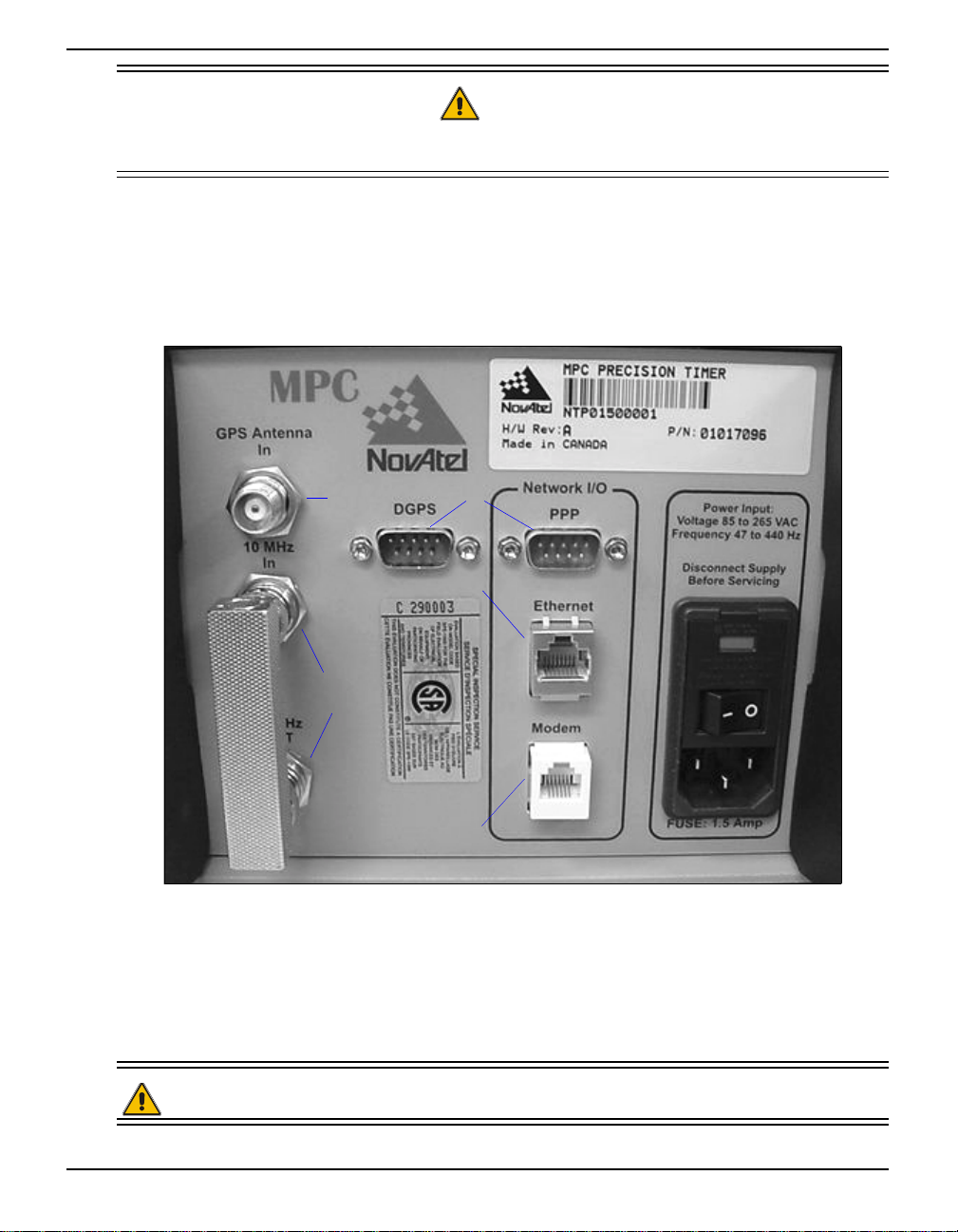
The connections on the rear panel and their connector types are shown on Figure 3.
Figure 3: Close-up of Connectors on Rear Panel
TNC
BNC
DB9
RJ45
RJ11
Each connector is keyed to ensure that the cable can be inserted in only one way, to prevent damage to
both the MPC and the cables. Furthermore, the connectors that are u sed to mate the cables to the MPC
require careful insertion and removal. Observe the following when handling the cables.
· To insert a cable, make certain you are using the appropriate cable for the port - the serial
cable has a different connector (DB9) than the GPS Antenna In (TNC), or the Modem
(RJ11), or the Ethernet (RJ45) connectors.
WARNING: DO NOT PULL DIRECTLY ON THE CABLES.
MPC User Manual Rev 0D 19
Page 20
Chapter 3 MPC Setup Considerations
3.2.1 10 MHz In and 10 MHz Out
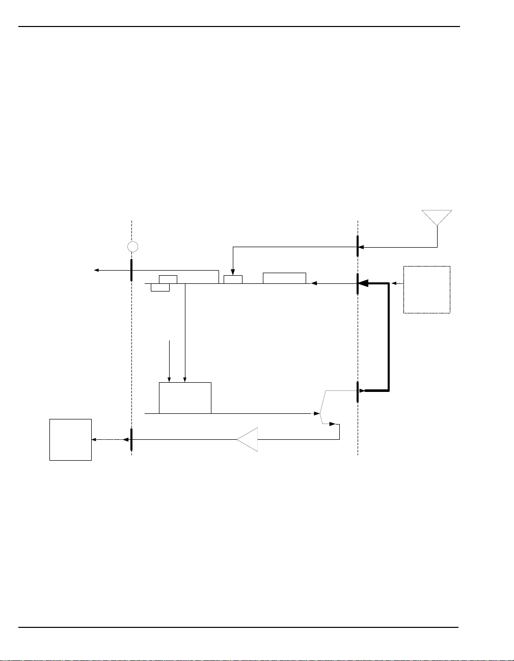
There are two BNC connectors on the back of the MPC for 10 MHz In and 10 MHz Out. These two
connectors are looped using an RF Loop-Back connector. Therefore by default, the 10 MHz Oven
Controlled Crystal Oscillator (OCXO) in the MPC is looped back to the GPS receiver. The GPSCard
phase locks to the 5 or 10 MHz reference signal supplied to the rear panel 10 MHz port.
The RF Loop-Back connector can be removed if you prefer to provide your own external oscillator
through the 10 MHz In connector. In this case, the EXTERNALCLOCK command, refer to Volume 2
of the OEM4 Users’ Guide and List Current Configuration on Page 63, allows you to set up an
external oscillator and its frequencies.
Figure 4 shows how the clock card and Euro4 card w ork toget her us ing the loo p conn ector or us i ng a
user-supplied external clock.
Antenna
GPS Antenna
In
10 MHz In
Back Panel of the MPC
Optional
external
oscillator may
be used if loop
back connector
is removed.
1PPS Out
Oscillator LED, when
blue, indicates that the
internal OCXO is
powered on.
Front Panel of the MPC
Power
On/Off
Control
GPSCard
Frequency Control
Optional user-
supplied
external
device may be
synchronized
with the MPC.
10 MHz Out
10 MHz Oscillator
Clock Card
Amp
10 MHz Out
Figure 4: 10 MHz In/Out Data Flow
For further information on the signals or connector type for the 10 MHz In and 10 MHz Out ports,
please see Appendix A, Input/Output Connectors on Page 78.
3.2.2 DGPS
A data serial cable is needed to connect the MPC from the DGPS connector to an external device.
The Differential GPS (DGPS) communication port is bi-directional and factory conf igured for RS232.
It is typically used to communicate DGPS broadcast data to transmitting radio equipment.
For communication to occur, the MPC serial port configuration must match that of the external
20 MPC User Manual Rev 0D
Page 21

MPC Setup Considerations Chapter 3
device’s. The MPC’s default po rt settings are [RS232, 9600 BPS, no parity, 8 data bits, 1 stop bit, no
handshaking, and echo of f]. Chan ging the def ault settings can be easily accomplished by means of the
COM command (which is de scribed in Volume 2 of the OEM4 Users’ Guide).
For information on issuing commands to the MPC via the Modulated Precision Clock website, see
List Current Configuration on Page 63.
For further information on the signals, or connector pin-outs, for this serial port, please see Section
A.3, Port Pin-Outs on Page 79.
See Appendix D, Replacement Parts on Page 97, if you need to consult a list of NovAtel part
numbers.
3.2.3 Network I/O
In the Network I/O group of connectors there is an RJ11 Modem jack, an RJ45 Ethernet jack and an
RS232 PPP port.
Data and receiver information can be viewed, conf i gur ed and do wnloaded via th e internet u sing thes e
connections and the Modulated Precision Clock website. See also Section 4.2, Configuring the
Network on Page 25 and Chapter 5, VFD Menus on Page 40.
3.2.3.1 PPP
The Point to Point Protocol (PPP) connector is an RS232 communications port to support TCP/IP
communication using a “Direct Connection” to a user supplied computer. See also Section 4. 2.2,
Modem or Direct Connect (PPP) Client on Page 26.
The PPP connector provides a direct TCP/IP data link from the MPC to a computer that supports this
protocol.
For further information on the signals, or connector pin-outs, for this serial port, please see Section
A.3, Port Pin-Outs on Page 79.
3.2.3.2 Ethernet
Connect to the internet from this port using a Patch RJ45 cable. See also Section 4.2.1, Ethernet
Connect on Page 25.
3.2.3.3 Modem
The MPC contains an internal modem. You can connect to the MPC by phoning in from your
computer/modem, or you can configure the MPC to phone out to an Internet Service Provider or
internal network (intranet). See also Section 4.2.2, Modem or Direct Connect (PPP) Client on Page
26.
Use a Patch RJ11 cable to connect the MPC from the Modem port to the telephone system.
MPC User Manual Rev 0D 21
Page 22

Chapter 3 MPC Setup Considerations
3.2.4 Power
After initial connection of the power source to the receiver and pressing the power switch on the back
of the unit (see Figure 3 on Page 19), the Power LED on the front of the MPC glows red.
The PWR button on the keypad is used to access the MPC Shutdown Type screen in the VFD menus,
see Pages 45. Choosing REBOOT will cause the embedded PC to reboot. Choosing POWERDOWN
will terminate the programs running on the embedded PC and cause the PC buffers to be flushed to the
hard drive. The keypad will be unusable again until the power switch is turned off, then on, and the
VFD is visible again.
The VFD display will screen-save and appear black after 5 minutes of inactivity. Hit any key on the
VFD keypad for it to be restored.
The MPC requires an input supply voltage that comes from a normal power source of 110/ 220 vo lts at
50/60 Hz AC throug h its 3-pin power connector. The MPC has an internal power modul e that does th e
following:
· filters and regulates the supply voltage
· protects against over-voltage, over-current, and high-temperat ure conditions
· provides automatic reset circuit protection
WARNING: 1. Supplying the MPC with an input voltage that is below 100 VAC will cause
the unit to suspend operation. An input voltage above 240 VAC may
physically damage the unit.
2. D iscon nect the po wer source bef ore serv icing t he power conn ector’ s 1.5
Amp fuse.
The Power Input connector on the MPC contains a 1.5 Amp fuse that can be serviced as long as the
MPC is disconnected from power.
As is also described on Page 42, the GPS row in the MPC System Status screen of the VFD menus
provides information and error m essages in cluding an y to d o with v oltage. Also, the RXHWLEVELS
log, refer to Volume 2 of the OEM4 Users’ Guide, contains environmental and voltage parameters.
The data logging mechanism is designed to be robust and to endure power interruptions (and similar
disruptive events) with minimum loss of data. In this situation, allow for your data to be possibly
reduced by several seconds up to a maximum of a minute. To the extent possible, error messages
attempt to describe the problem. If you require further information on this topic, please refer to the
description of the RXSTATUS log i n Volume 2 of the OEM4 Users’ Guide.
* The MPC is designed for continuous operation. However, if you need to power down the unit, it
is recommended that you always use the MPC Shutdown Type menu, see Page 45. Then give the
internal operating system a few minutes to flush its cache buffers to the hard drive, and turn off
the power at the power switch.
For a listing of the required input supply voltages, see Appendix A, MPC Specifications on Page 77.
For more information on the supplied 3-pin power cable, see A.4, Power Cable on Page 80.
22 MPC User Manual Rev 0D
Page 23
MPC Setup Considerations Chapter 3
3.2.5 RF Port & Cables
The GPS Antenna In connector is bi-directional in that it accepts RF signals from the antenna, and it
supplies DC power to the low-noise amplifier (LNA) of an active antenna. It has a TNC fema le
connector. Power to this p ort can be disabled via the ANTENNAPOWER command, refer to Volume 2
of the OEM4 Users’ Guide.
The receiver obtains a partially filtered and amplified GPS signal from the antenna via the coaxial
cable. The RF section performs the translation from the incoming RF signal to an IF signal usable by
the Euro4’s digital section. It also supplies power to the active antenna’s LNA through the coaxial
cable while maintaining isolation between the DC and RF paths.
The RF section can reject a high level of potential interference (e.g., MSAT, Inmarsat, cellular phone,
and TV sub-harmonic signals). For further information on the signals or connector type for the GPS
Antenna In connector, please see Appendix A, Input/Output Connectors on Page 77.
While there may be other coaxial cables on the market that might also serve the purpose, please note
that the performance specifications of the MPC are guaranteed only when it is used with NovAtelsupplied RF cables.
3.3 Front Panel Functionality
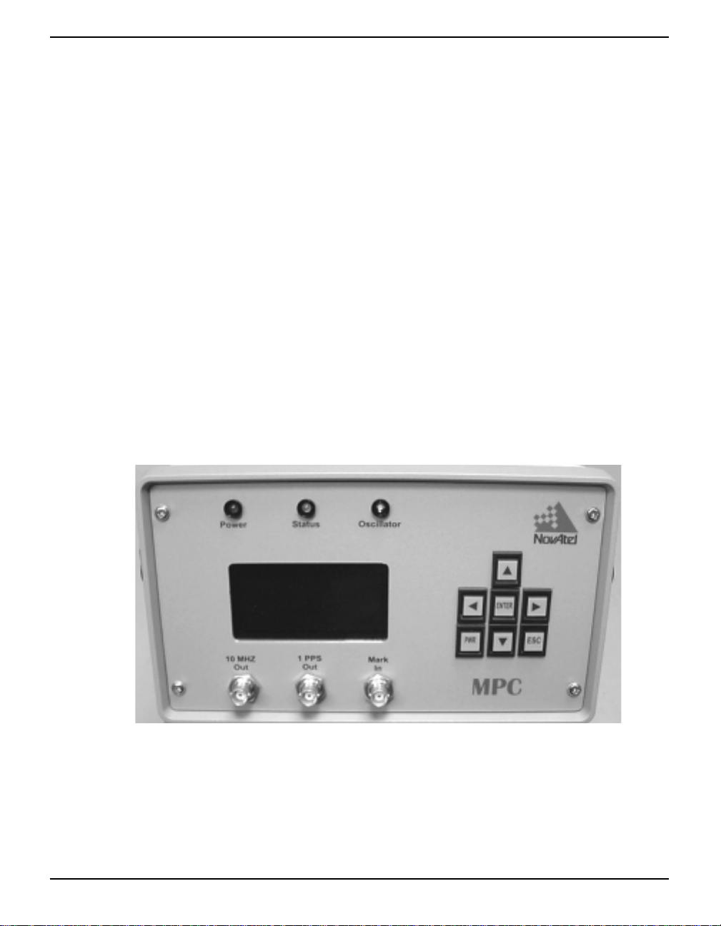
As shown in Figure 5, the MPC's front panel has a VFD display with a keypad including an ENTER
and ESC button, see Chapter 5, VFD Menus on Page 40, and a power (PWR) button, see Section
3.2.4, Power on Page 22.
Figure 5: MPC Front Panel
There are three color indicators above the VFD screen:
Power This LED glows red while power is applied
Status This diagnostic LED glows green to indicate satellite tracking and computed solution. If the
indicator is not illuminated, the receiver is not tracking satellites properly. The GPS row in
the MPC System Status screen of the VFD menus provid es st atus in format ion, see Page 42
Oscillator This LED glows blue when the internal OCXO is powered on
MPC User Manual Rev 0D 23
Page 24

Chapter 3 MPC Setup Considerations
3.3.1 I/O Connectors and Cables
Below the VFD screen on the front of the MPC are three BNC female connectors: 10 MHz Out, 1PPS
Out and Mark In.
3.3.1.1 10 MHz Output
The 10 MHz output provides a high-stability reference 10 MHz frequency that is by default phase
locked to GPS time. It permits the synchronization of other equipment requiring an extremely stable
reference signal of 10 MHz. See also Figure 4 on Page 20.
The steering of the internal OCXO is controlled by the CLOCKADJUST, EXTERNALCLOCK and
CLOCKCALIBRATE commands. The status of the clock steering process is provided by the
CLOCKSTEERING log and the time history plots on the Modulated Precision Clock website.
Refer to Volume 2 of the OEM4 Users’ Guide for more information on these commands and logs. For
details on time plots, please see Section 6.1.3.1, Time Plots on Page 67.
3.3.1.2 1PPS Output
Upon determination of position-time, the receiver will align the one pulse per second (1PPS) signal to
the GPS epoch. Its specifications and electrical characteristics are descr ibed in Front Panel 1PPS Out
on Page 78. From this time onwards the 1PPS triggers every second. By default, the OCXO frequency
is adjusted to maintain the 1PPS signal within 10 ns of GPS time. The bandwidth of the OCXO clock
steering loop is adjustable with a default value of 1/100 Hz or approximately a 15 minute time
constant.
The CLOCKADJUST command is used to enable or disable the clock steering. The
CLOCKCALIBRATE command is used to set the parameters of the clock steering loop. It also
provides an auto-calibration procedure to find or reset the centre point and gain of the control loop.
Please refer to Volume 2 of the OEM4 Users’ Guide for details on these commands.
Immediately on start-up of the receiver, the 1PPS is active (at 1Hz) but it is not aligned to the GPS
epoch. The timing of the 1PPS will be adjusted when position-time is known.
1 Hz GPS measurements are taken on the 1PPS. These measurements include pseudorange, carrier
phase and Doppler.
3.3.1.3 Mark Input
The Mark In connector provides a connection for an input mark with an input pulse greater than 55 ns.
Time tags output log data to the time of the falling edge of the mark input pulse. Logs with the
ONMARK trigger will output when a trigger event passes the Mark In connector.
If you supply the reference frequency and 1 PPS signal, your 1PPS signal will be connected to the
Mark In connector. The receiver can be configured to adjust its internal 1PPS to match your 1PPS to
within 50 ns. Refer to the ADJUST1PPS command in Volume 2 of the OEM4 Users’ Guide.
24 MPC User Manual Rev 0D
Page 25

Chapter 4 Using the MPC
Before using MPC for the first time, ensure that you have followed the in stallation instructions of
Chapter 2, Quick Start and Chapter 3, MPC Setup Considerations, starting on Page 16.
CAUTION!: See the cautions on Page 11 of the Notice for a list of items you shou ld be aware
of as you set up and use the MPC.
4.1 Self-Test
When power is applied, it takes several minutes for the computer within the MPC to boot up. It takes
up to 15 minutes for the internal OCXO to warm up to a point where the frequency is stable enough to
track satellites.
Once powered and stable, the MPC performs the first phase of self-test functions. If no problems are
detected, the ST ATUS LED on the front of the MPC will glow green. You can monitor the MPC using
the VFD pane l Status menu and/or RXSTATUS log. Self-test status of the internal GPSCard can be
examined via the self-status word in the RANGE and RXSTATUS data logs, refer to Volume 2 of the
OEM4 Users’ Guide.
System and logging statu s reports may also be seen via the internet on the Modula te d Precision Clock
website, see Section 6.2, MPC Firmware Upgrades & Updates starting on Page 75.
If the MPC fails its self-test, please refer the problem to your dealer or NovAtel Customer Service.
4.2 Configuring the Network
There are three connectors on the back panel of the MPC that allow connectivity to the internet:
• Ethernet
• Modem
• Direct (PPP)
These MPC internet ports, user security, and internet method can be configured using the menus on
the front panel of the MPC. A limited amount of the system status may also be viewed in these menus.
See Chapter 5, VFD Menus on Page 40 for more details.
How to set up the different ports for connection to the internet and then how to connect to the internet
from each port is described in the following sections.
4.2.1 Ethernet Connect
The Network Administrator must use the Configure Ethernet menus as described in Section 5.2.4,
Configure Ethernet on Page 46 to decide whether or not the IP address is assigned automatically via a
Dynamic Host Configuration Protocol (DHCP) server on the local network (intranet). If AUTO IP in
MPC User Manual Rev 0D 25
Page 26

Chapter 4 Using the MPC
the menu is changed to ‘YES’, then the IP, SUBNET and GATEWAY rows will be assigned
automatically upon activation.
Connect an RJ45 cable from your local internet or intranet wall jack to the Ethernet port on the MPC.
You may receive an IP address or a “static” IP location on your internal network (intranet) given by
your Network Administrat or to use as a URL. An IP loc ation associates an IP address with a name, for
example “MPC1”, in your Domain Name Server (DNS).
Open your internet browser and connect to the internet on a PC. In the Address field of your internet
browser, type in the IP address or static IP location to go to the Modulated Pr ecision Clock website for
your MPC. The following URLs are fictional examples:
http://123.123.123.123/
http://mpc1/
You can monitor your connection status i n the Connect menu described in Section 5.2.2, Connect on
Page 44.
Details on the Modulated Precision Clock website login and features can be found in Section 6.1
starting on Page 49.
4.2.2 Modem or Direct Connect (PPP) Client
Use the Configure Modem menus as described in Section 5.2.5, Configure Modem on Page 47 or the
Configure Direct menu as described in Section 5.2.6, Configu r e Direct (PPP) on Page 48 to set up the
modem direct connection. Then decide whether or not the IP address is assigned automatically for the
MPC. If AUTO IP in the CONFIG MODEM or CONFIG DIRECT menu is changed to ‘YES’, then
the IP row will be assigned automatically upon activation.
Connect an RJ11 cable from a phone jack to the Modem port on the MPC, or an RS232 cable from the
PPP port on the MPC to a COM port on your PC.
In order to install a modem or PPP connection for your PC follow the res t of th is section.
On your PC select Start | Settings | Control Panel from the taskbar and click on the Modems icon as
seen in Figure 6.
Figure 6: Modems Icon
26 MPC User Manual Rev 0D
Page 27
Using the MPC Chapter 4
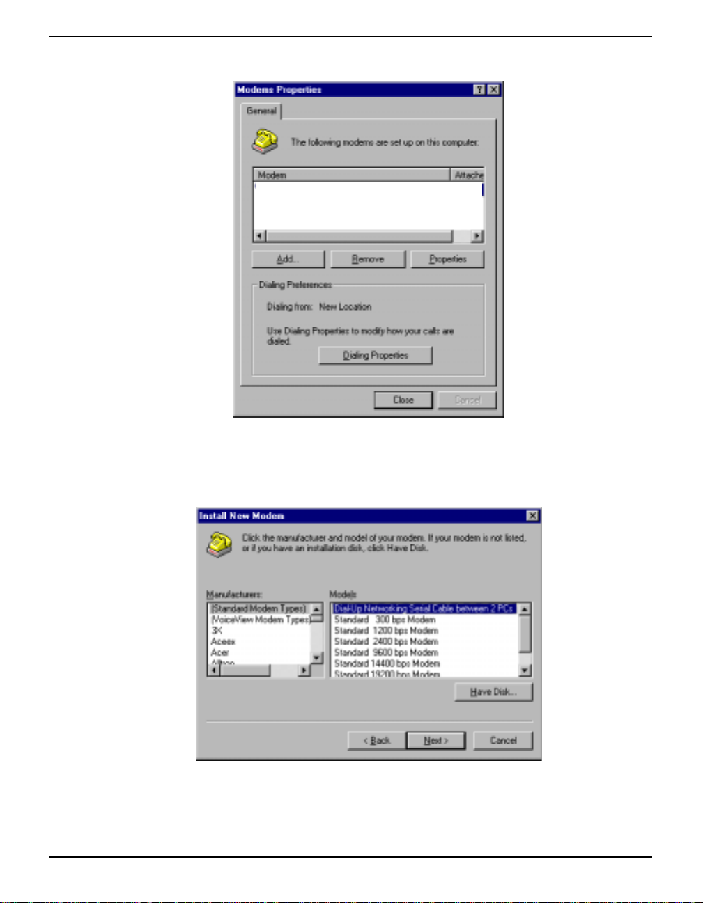
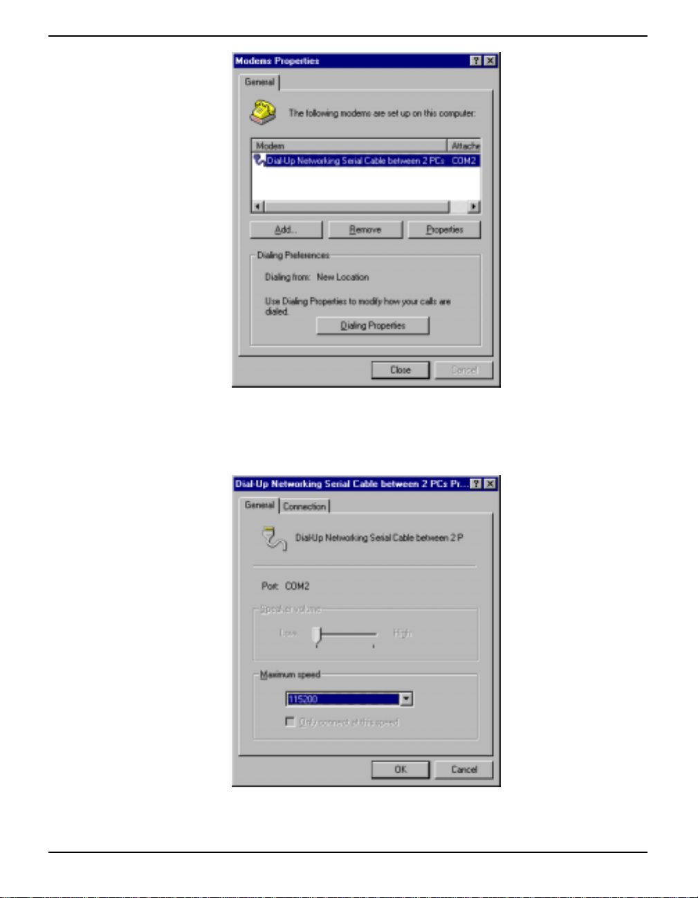
The Modems Properties dialog will appear as seen in Figure 7.
Figure 7: Modems Properties
Click on the Add button to install the modem or PPP connection and the Install New Modem dialog
will appear as seen in Figure 8.
Figure 8: Install New Modem
In the Install New Modem dialog, select a modem or direct connection from the list. Insert your
operating system install disk into your CD drive (e.g. Windows NT) and click on the Have Disk
MPC User Manual Rev 0D 27
Page 28
Chapter 4 Using the MPC
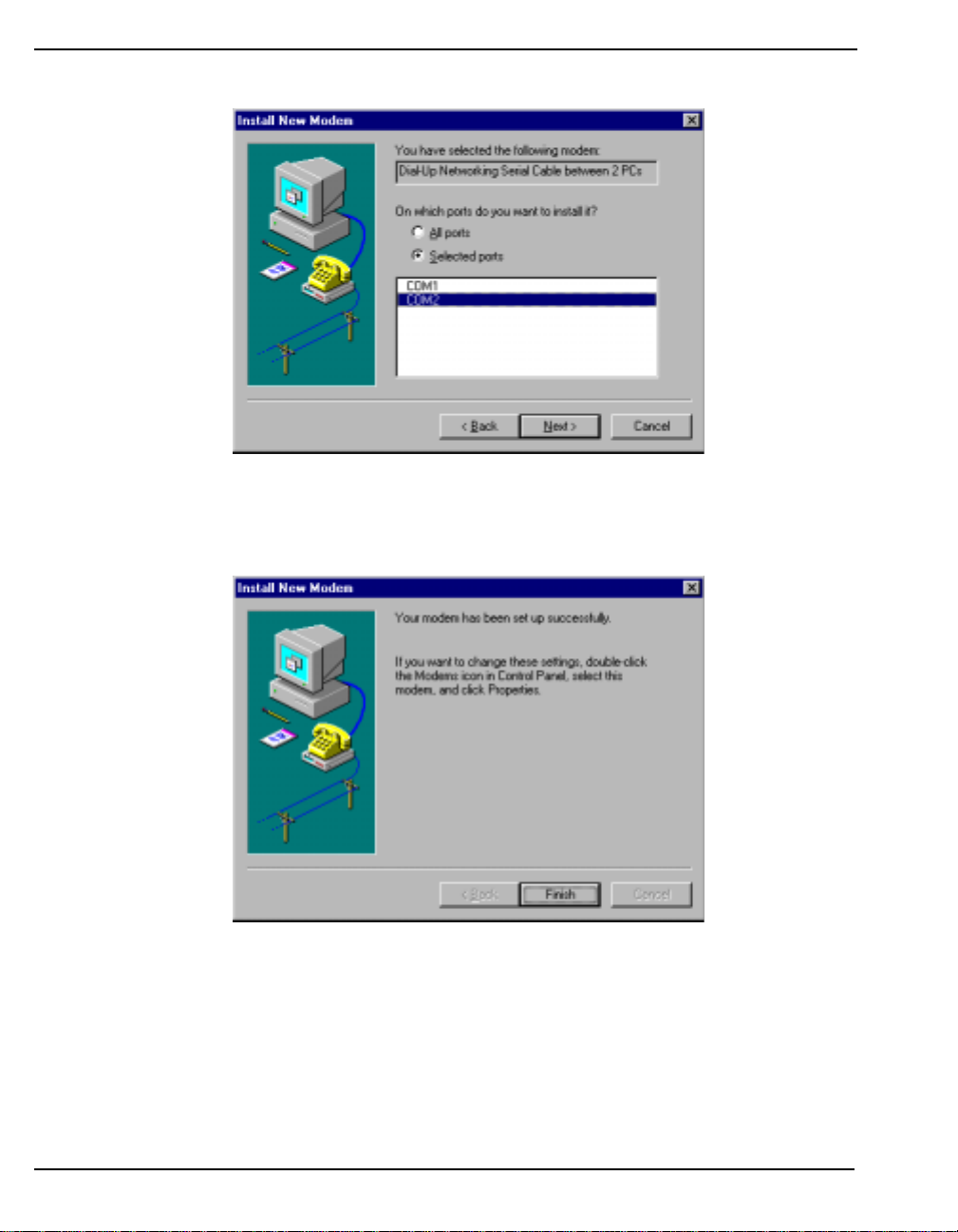
button. The modem installation will continue as seen in Figure 9.
Figure 9: Modem Installation Continued
Click in the Selected Ports field and select the PC port that your MPC will be connected to from the
list. Click on the Next button.
Figure 10: Modem Installation Finish
Click on the Finish button, see Figure 10, and you will be returned to the Modems Properties dialog,
see Figure 11 on Page 29, but you will now see the modem you installed.
28 MPC User Manual Rev 0D
Page 29
Using the MPC Chapter 4
Figure 11: Ins talled Modem Properties
Select your connection in the Modem column and click on the Properties button. Its properties dialog
will appear as seen in Figure 12.
Figure 12: Connection Properties
In the General tab, ensure that the Maximum Speed is set to 115200 to match the MPC. Click on the
MPC User Manual Rev 0D 29
Page 30
Chapter 4 Using the MPC
OK button.
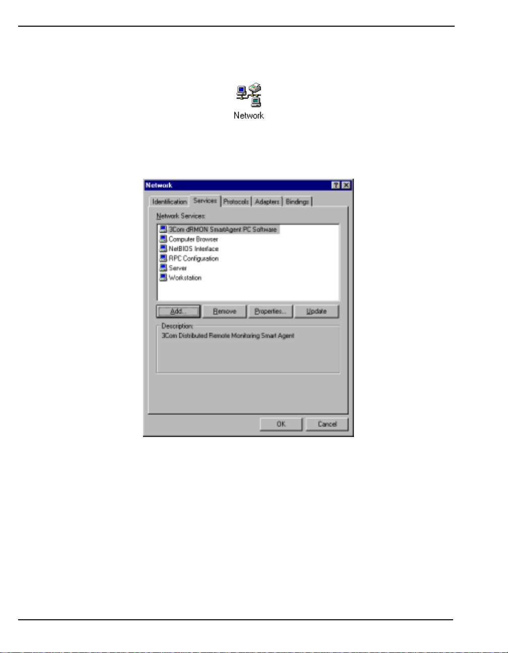
Return to the Control Panel and select the Network icon as seen in Figure 13.
Figure 13: Network Icon
The Network dialog appears as seen in Figure 14.
Figure 14: Network Services
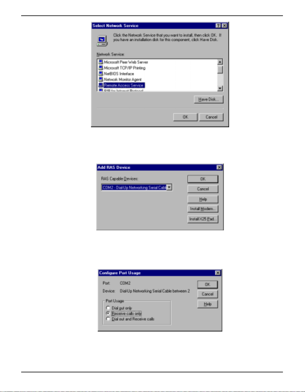
Select the Services tab in the Network dialog. Click on the Add button to add a Remote Access
Service (RAS) and the Select Network Service dialog will appear as seen in Figure 15 on Page 31.
30 MPC User Manual Rev 0D
Page 31
Using the MPC Chapter 4
Figure 15: Select Network Service
Select Remote Access Service and ensure your operating system install disk is in the PC disk drive.
Click on the Have Disk button and the Add RAS Device dialog will appear as seen in Figure 16.
Figure 16: Add RAS Device
Select your connection in the RAS Capable devices field and click on t he OK button. The Configure
Port Usage dialog will appear as seen in Figure 17
Figure 17: Configure Port Usage
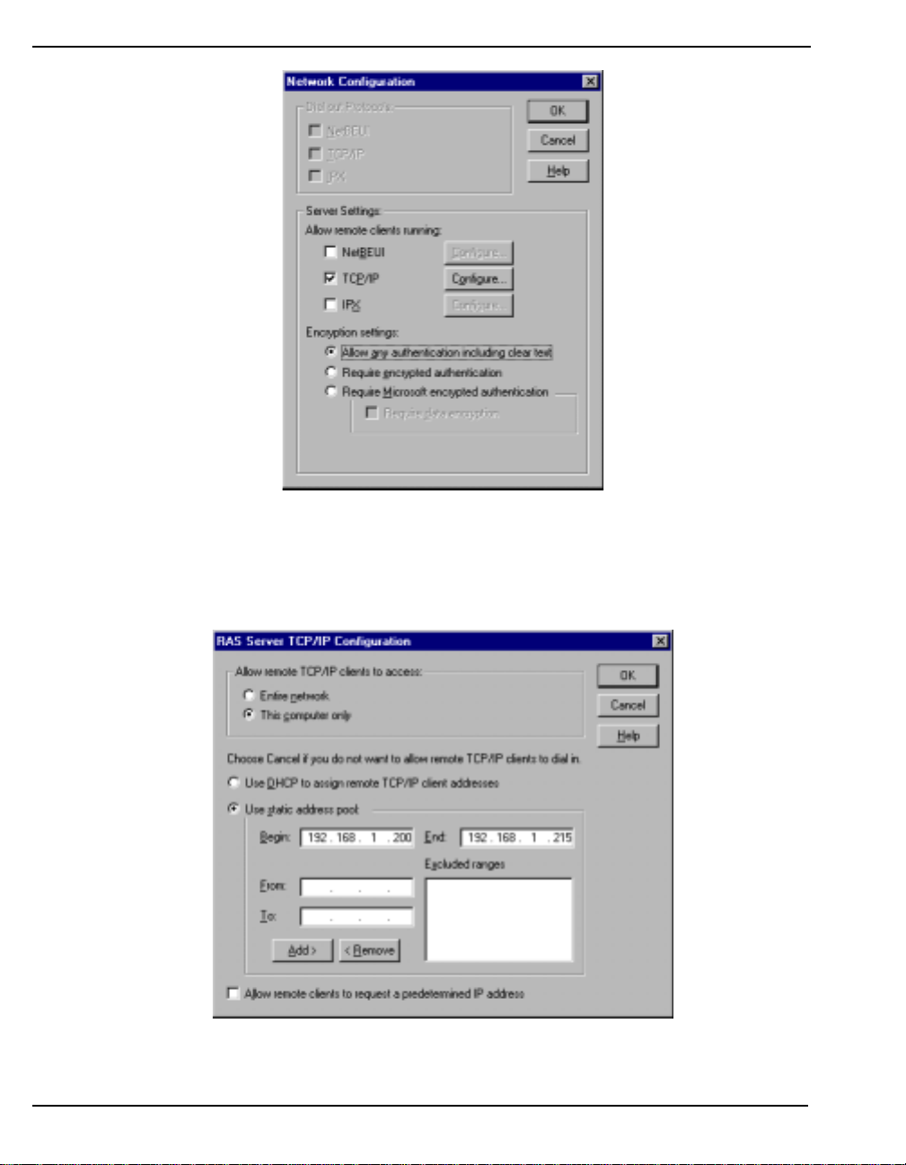
Click in the Receive Calls Only field and then click on the OK button. The Network Configuration
dialog will appear as seen in Figure 18 on Page 32.
MPC User Manual Rev 0D 31
Page 32
Chapter 4 Using the MPC
Figure 18: Network Configuration
Check the TCP/IP check box and click in the Allow Any Authentication Including Clear Text field.
Click on the Configure button next to the TCP/IP check box and the RAS Server TCP/IP
Configuration dialog will appear as seen in Figure 19.
Figure 19: RAS Server TCP/IP Configuration
Click in the Use This Computer Only field and then the Use Static Address Pool field. Enter the Begin
32 MPC User Manual Rev 0D
Page 33
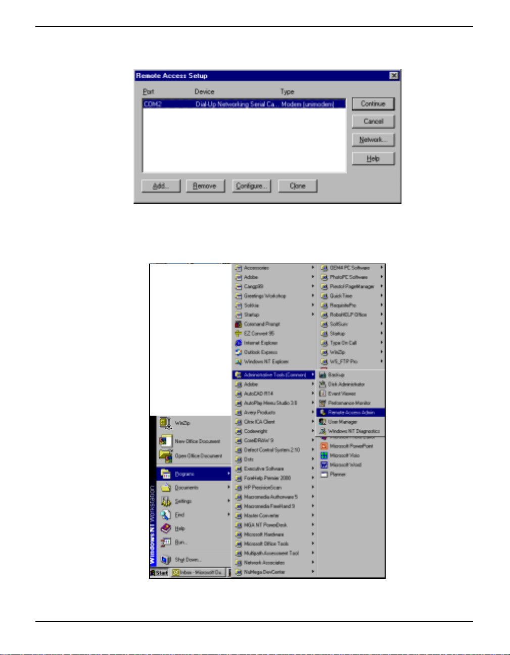
Using the MPC Chapter 4
and End addresses as shown in Figure 19 on Page 32. Click on the OK button and the Remote Access
Setup dialog will appear with your connection port, device and type showing as in Figure 20.
Figure 20: Remote Access Setup
From the taskbar, select Start | Programs | Administrative Tools (Common) | Remote Access Admin,
see Figure 21.
Figure 21: Remote Access Admin Route
MPC User Manual Rev 0D 33
Page 34
Chapter 4 Using the MPC
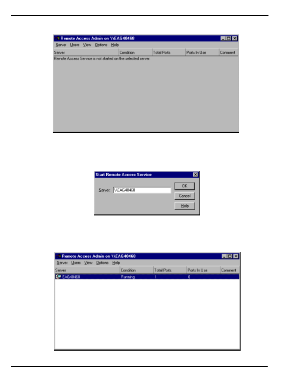
The Remote Access Admin dialog will appear as seen in Figu re 22.
Figure 22: Remote Access Admin on PC
From the main menu, select Server | Start Remote Access Service and the Start Remote Access
Service dialog will appear as seen in Figure 23
Figure 23: Start Remote Access Service
You may see some service control messages before the Remote Access Admin dialog reappears with
your connection status visible, see Figure 24.
Figure 24: Remote Access Admin
34 MPC User Manual Rev 0D
Page 35
Using the MPC Chapter 4
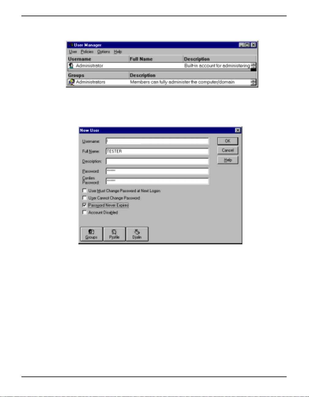
On the taskbar, select Start |Administrative Tools (Common) || User Manager for the User Manager
dialog to appear as seen in Figure 25
Figure 25: User Manager
From its main menu, select User | New User and the New User dialog will appear as shown in Figure
26.
MPC1
Figure 26: New User
Enter a User Name and Password that the MPC will use to ‘sign on’ to your computer, in bold
uppercase letters only because only uppercase letters can be entered in the VFD screens, in the
Username and Password field s. R e-en ter yo ur p ass w ord in t he Confirm Password field. You may also
enter text in the Full Name field, such as MPC1, for easy identification.
Check in the Password Never Expires check box and then click on the Dialin button. The Dialin
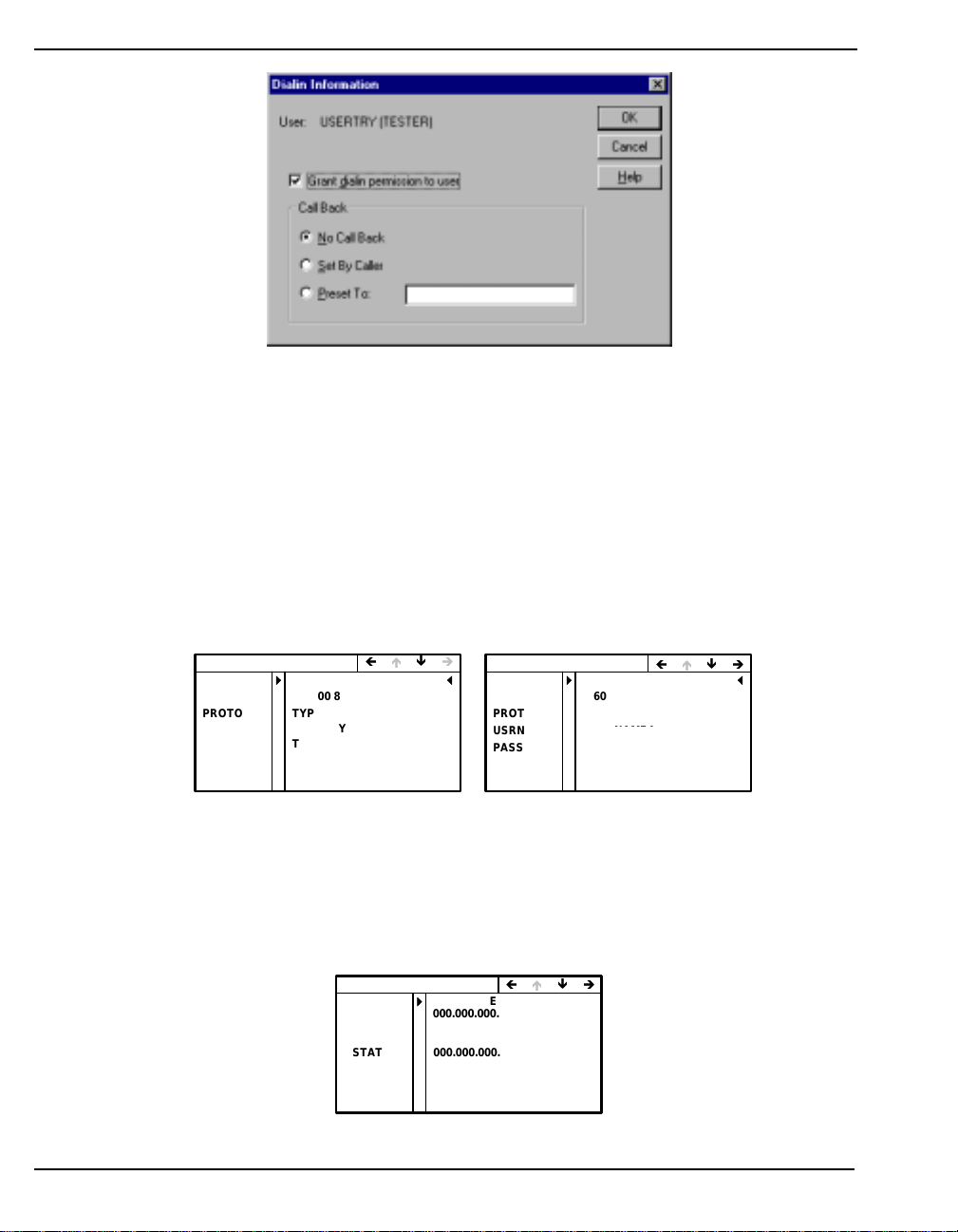
information dialog will appear as seen in Figure 27 on Page 36.
MPC User Manual Rev 0D 35
Page 36
Chapter 4 Using the MPC
Figure 27: Dialin Information
Check the Grant Dialin Permission to User check box and click in the No Call Back field. Click on the
OK button.
Restart your PC for the new settings to take effect.
Ensure your MPC is powered on. At the MPC VFD screen, use the navigation button to go to the
CONFIG DIRECT, or CONFIG MODEM, menu. Set up a client as described in Section 5.2.3,
Configure Client on Page 45. If you have a PPP connection, use the MPC navigation buttons to go to
the CONFIG DIRECT menu, see also Section 5.2.6, Configure Direct (PPP) on Page 48. Or, if you
have a modem connection, use the MPC navigation buttons to go to the CONFIG MODEM menu, see
also Section 5.2.5, Configure Modem on Page 47. Examples of both menus are shown in Figure 28.
CONFIG DIRECT
MPC
PC COM
PROTO TYPE:PPP
USRNAME
PASSWRD
SOURCE AUTO IP:NO
IP ADDR 000.000.000.000
CLIENT
115200 8NONE1 N
USERTRY
USERNAME5
TESTER
PASSWORD5
YES
Ì ÍÏÎ
CONFIG MODEM
PHONE
PC COM
PROTO
USRNAME USERNAME4
PASSWRD PASSWORD4
SOURCE AUTO IP:NO
IP ADDR 000.000.000.000
19002446262
57600 8 NONE 1 N
TYPE:PPP
USERTRY
TESTER
YES
ÌÍÏÎ
Figure 28: Config Direct and Modem Menus
Select your protocol (PROTO: TYPE) as PPP. Enter the same User Name and Password that you set
up for the MPC to ‘dial in’ to your computer. In the SOURCE row, select AUTO IP:YES.
Use the MPC navigation buttons to go to the MPC CONNECT menu , see also Sect ion 5.2 .2, Co nnect
on Page 44. An example of the MPC CONNECT menu is shown in Figure 29.
MPC CONNECT MENU
ENET
ESTATUS
MODEM
MSTATUS
DIRECT CONNECT:NO
DSTATUS
CONNECTED
000.000.000.000
198.161.68.216
CONNECT:NO
000.000.000.000
192.168.001.201
000.000.000.000
ÌÍÏÎ
YES
Figure 29: MPC Connect Menu
36 MPC User Manual Rev 0D
Page 37
Using the MPC Chapter 4
Change the DIRECT row status to CONNECT:YES. Once you have pressed the ENTER key, the
MPC will attempt to ‘dial in’ to the host computer. If successful, the IP address will appear in the
DSTATUS row if there are no errors, and an error message will appear if there is an error.
Open your internet browser and type in the IP address shown in the DSTATUS row as the URL.
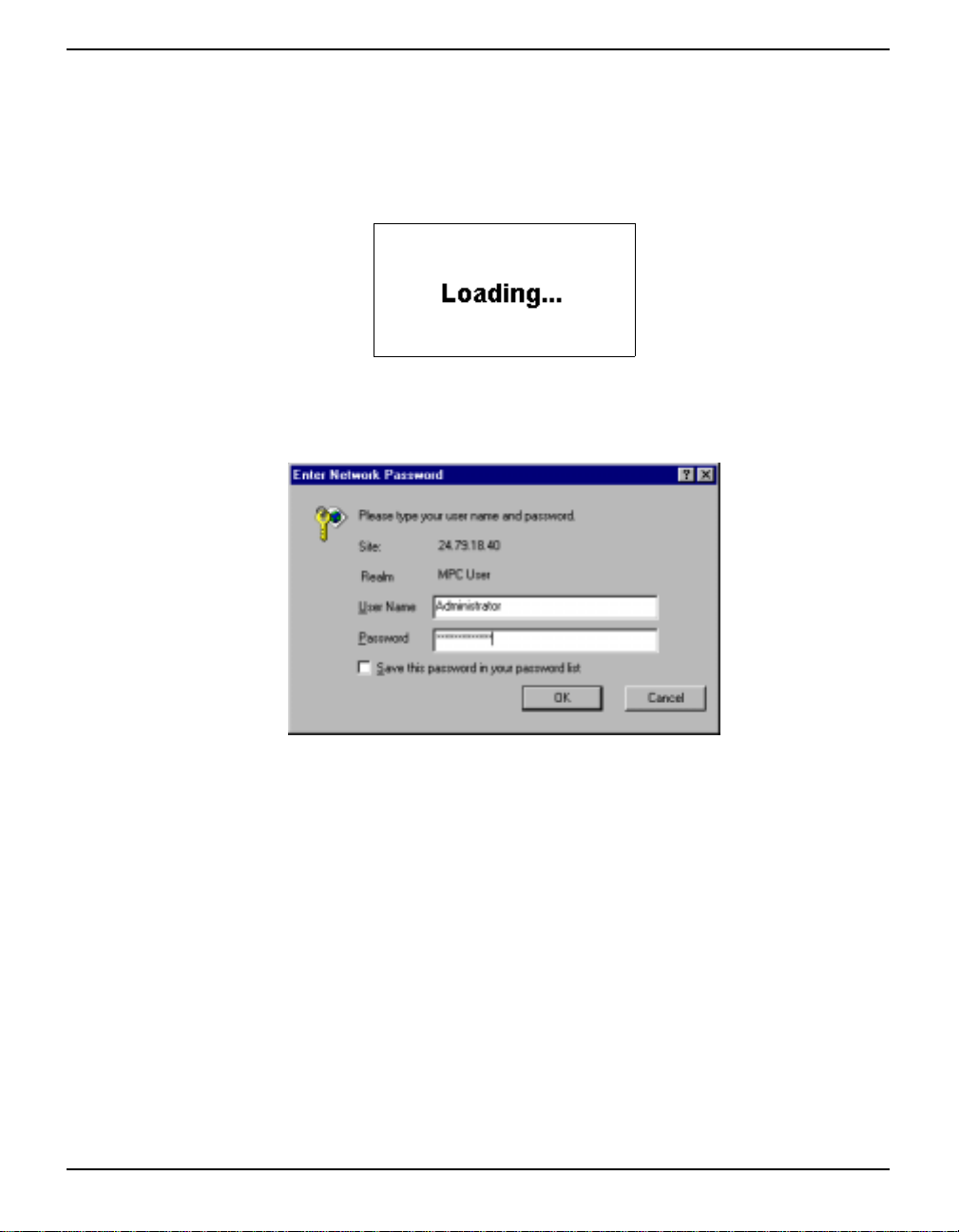
If successful, you should see the loading screen as shown in Figur e 30.
Figure 30: Loading Screen
This is followed by the Log In dialog as shown in Figure 31.
Figure 31: Website Password
At this point, you can use the p reconfigured Ad ministrator User Name an d Password to ‘log on’ to the
Modulated Precis ion Cl ock website:
User Name: Administrator
Password: Administrator
If you are successfully logged on to the Modulated Precision Clock website, you should see its home
page, see Figure 43, Modulated Precision Clock Home Page on Page 49.
We recommend that you change the Administrator Password to protect your MPC from unwanted
access. If you forget your Administrator Password, you can set up a new Client User Name and
Password through the VFD CONFIG CLIENT menu, see Section 5.2.3, Configure Client on Page 45
and Figure 32 on Page 38, and toggle the ADMIN row to YES.
MPC User Manual Rev 0D 37
Page 38

Chapter 4 Using the MPC
CONFIG CLIENT
USRNAME
PASSWRD
ADMIN
LOGGING
FTP
STATUS
SUBMIT INFO:NO
ABCDEFG
TUVWXYZ
PRIV:NO
CONTROL:NO
ACCESS:NO
VIEW:NO
ÌÍÏÎ
Figure 32: CONFIG CLIENT Menu
You can add\edit users and their privileges by choo sing S etup in the Mod ulated P recisio n Cloc k home
page followed by the Set Up Users button. See also Section 6.1.2.7, Set Up Users on Page 65.
Details on the Modulated Precision Clock website login and features can be found in Section 6.1
starting on Page 49.
You can also monitor your connection status in the VFD CONNECT menu described in Section 5.2.2,
Connect on Page 44.
4.3 Communication
After a network connection has been established, the Modulated Precision Clock website is used for
all other aspects of the system such as configur ations , monit oring an d data collecti on. See Section 6.1 ,
starting on Page 49 for details on the Modulated Precision Clock website.
Some examples of the types of information that can be monitored via the website are:
•Temperature
• Number of satellites
• Clock feedback
• Receiver messages
• Multipath
• Signal strength
• Sky coverage
4.3.1 Logging Data
The most basic activity is logging raw data. Each l ogging sess ion (one uninterru pted period of t ime) is
stored on the internal hard disk and may also be downloaded via the Modulated Precision Clock FTP
site.
MPC records raw data in the form of logs, which are written to the hard disk as configured in the
Modulated Precis i on Clock website. If you wanted to analyze the data in these logs yourself, the
details of the logs are documented in Volume 2 of the OEM4 Users’ Guide.
4.3.2 Differential GPS
If you are using your MPC as a reference or remote station to receive and transmit differential
corrections, you will need to provide a data link between the reference station and rover(s). Generally
38 MPC User Manual Rev 0D
Page 39

Using the MPC Chapter 4
a data link capable of data throughput at a rate of 2400 bits per second or higher is sufficient for the
examples shown below. The external device is connected to the MPC’s DGPS port with a usersupplied RS232 cable.
Pre-configure the MPC as a base station via the Modulated Precision Clock website, see Set Up Base
Station on Page 63 for details.
Pre-configure a rover/remote station, for example a NovAtel ProPak or DL-4 receiver, as follows:
interfacemode port rx_type tx_type
For example:
RTCA interfacemode com3 rtca none
RTCM interfacemode com3 rtcm none
CMR interfacemode com3 cmr none
* The DGPS port on the back of the MPC is connected internally to COM3 of the Euro4 GPSCard.
MPC commands can be issued via the Modulated Precision Clock website, see List Current
Configuration on Page 63 for details.
4.3.3 Errors
In the case of a power interruption or similar disruptive event, during a data-recording session, allow
for your data to be possibly reduced by several kilobytes. To the extent possible, error messages, refer
to the RXSTATUS log in Volume 2 of the OEM4 Users’ Guide and the GPS, attempt to describe the
problem. As is described on Page 31, the GPS row in the MPC System Status screen of the VFD
menus also provides status information.
* The MPC is designed for continuous operation. However, if you need to power down the unit, it
is recommended that you always use the MPC Shutdown Type menu, see Page 45. Then give the
internal operating system a few minutes to flush its cache buffers to the hard drive, and turn off
the power at the power switch.
MPC User Manual Rev 0D 39
Page 40
Chapter 5 VFD Menus
The front panel of MPC has a Vacuum Fluorescent Display (VFD) with 7 interaction keys. The panel
consist of four navigational, a combination edit/enter, a power, and an escape key.
The main functions of the VFD menu are:
• MPC Status
• MPC Connect
• Configure Client
• Configure Ethernet
• Configure Modem
• Configure Direct (PPP)
Accompanying this manual is a water/tear proof VFD Menus Quick Look Guide for on the fly
referencing of menu locations.
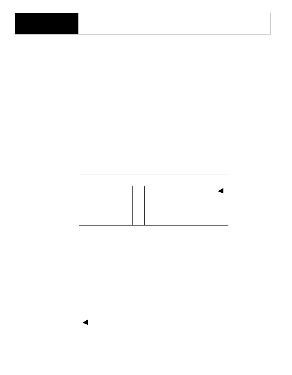
The current menu page being displayed is shown in the top left corner of the VFD screen. Figure 33
shows the layout of the VFD area.
Functionality
Row Labels
Figure 33: VFD Areas
The VFD areas are defined as:
• Functionality: The title of the current menu page.
• Main Data Display: Current data and d epen ds on the active Functionality.
• Row Labels: Row labels for the data being displayed in the Main Data Display
• Row Cursor: This cursor indicates the current row. It is especially useful for
choosing a row to edit.
• Navigation Aids: Four directional arrows show you how you can proceed through
the menu items for the current Functionality.
• : This edit cursor appears when the digits, or a group, in a row become
editable. See also Edit Digit Display and Edit Group Display on Page 41.
When the MPC is first powered up, and after an initialization period, the NovAtel logo appears
followed by the MPC SYSTEM STATUS menu, see Figure34 on Page 41 and also Page 42, from
Main Data Display
Cursor
Row
Navigation Aids
MPC User Manual Rev 0D 40
Page 41
VFD Menus Chapter 5
where you can access any of the main functionality menus and their columns.
MPC SYSTEM STATUS
TIME
DATE 1143 W 493408 S
GPS
EXT OSC LOCK ED
LOGGING
SPACE
COMPUTER TEST_9
12:33:24 GMT GPS
GPS SYSTEM OK
NOT ACTIVE
935840 KB
Ì ÍÏÎ
Figure 34: Opening Menu
5.1 Menu Access
The menu structure is arranged as columns of functionality. Each column may have several pages of
related data where a page can have up to seven rows.
Simple menu access is achieved by following the directional arrows in the top right of the VFD when
they appear (
direction. Pressing the <ESC> key continually will take you back through menu items until you return
to the top of the menu where you started.
There are two mechanisms for editing data, Edit by Digit and Edit by Group.
5.1.1 Edit Digit Display
Press the <ENTER> key to cause the t indicator to appear on the row you wish to edit, and a cursor
to appear under the first digit of that row. Cursor horizontally to the digit to be changed, then cursor up
to increase its value or down to decrease its value. A numeric values ranges from 0 to 9 and an alpha
character can be A to Z. Press the <ENTER> key again to save the new value.
← ↑ ↓ →). An arrow that does not appear signifies that there is no menu in that
Alpha-numeric fields can be shortened by toggling the characters to spaces. When the screen is
refreshed the spaces will disappear and leave you with a shortened entry. Address fields, such as IP
addresses, may have truncated values in the memory, for example ‘195.45.61.1’, but will appear
padded with zeroes, for example ‘195.045.061.001’, in the VFD menu.
* The VFD menus only provide upper case letters.
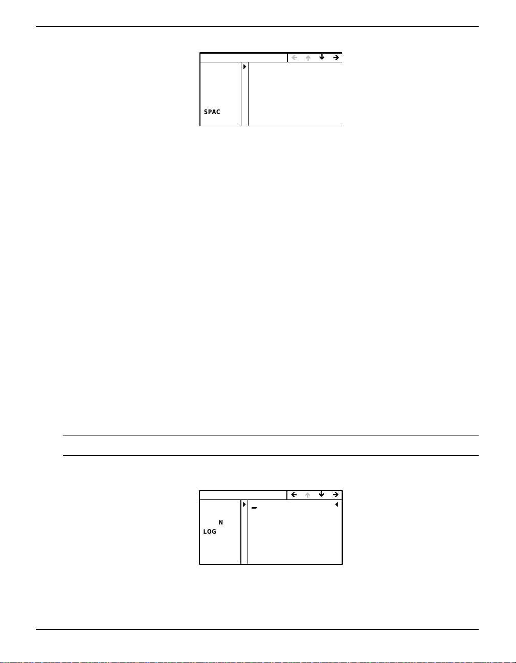
An example of a screen in edit digit display mode is shown in Figure 35.
CONFIG CLIENT
USRNAME
PASSWRD
ADMIN
LOGGING
FTP
STATUS
SUBMIT INFO:NO
ABCDEFG
TUVWXYZ
PRIV:NO
CONTROL:NO
ACCESS:NO
VIEW:NO
ÌÍÏÎ
Figure 35: Edit Digit Mode
5.1.2 Edit Group Display
Press the <ENTER> key to cause the t indicator to appear on the row you wish to edit, and the first
MPC User Manual Rev 0D 41
Page 42
Chapter 5 VFD Menus
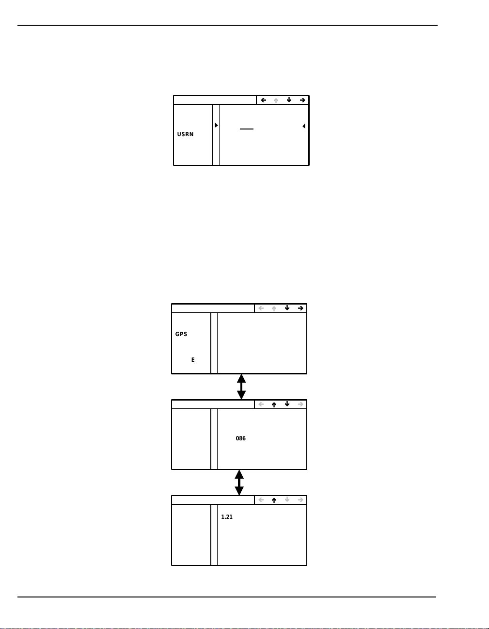
group in an editable row to be underlined. The left and right arrows move the cursor to the groups in
the row . The u p and down arro ws cycle throu gh a list of choices for that group v alue. An example o f a
group value that the cursor has been moved to, is the PPP value shown in Figure 36.
Press the <ENTER> key to return you to the top of the menu and save the new group value.
CONFIG MODEM
PHONE
PC COM
PROTO
USRNAME USERNAME4
PASSWRD PASSWORD4
SOURCE AUTO IP:NO
IP ADDR 000.000.000.000
1.900.244.6262
57600 8 NONE 1 N
TYPE:PPP
ÌÍÏÎ
Figure 36: Edit Group Mode
5.2 Menus
This section describes, and graphically gives examples of, the main menus and their sub-menus.
5.2.1 Status
The STATUS functionality group provides diagnostic information about the MPC. Its home screen
gives you MPC’s overall operational status and t he current GMT time. None of the rows in the column
are editable. Figure 37 shows the STATUS menus.
MPC SYSTEM STATUS
TIME
DATE 1143 W 493408 S
GPS
EXT OSC LOCKED
LOGGING
SPACE
COMPUTER PAT-TEST4
12:33:24 GMT
GPS SYSTEM OK
NOT ACTIVE
25946 MB
Ì ÍÏÎ
MPC POSITION INFO
POSTYPE
LAT
LON
# SATS 10
MPC RECEIVER INFO
SERIAL #
VERSION 1.210R1
MODEL
UI VER# 1.00
SINGLE POINT
N 51 06 59.0557
W 114 02 17.9690
1059.086 M MSLHEIGHT
SPA01240033
RT2
ÌÍÏÎ
ÌÍÏÎ
Figure 37: STATUS Menus
42 MPC User Manual Rev 0D
Page 43

VFD Menus Chapter 5
The information in this column is refreshed every second unless another column in the menus is being
edited. The 1 second refresh will continue once the editing has stopped. As seen from Figure 37 on
Page 42, there are several STATUS functionality categories:
• MPC SYSTEM STATUS
• TIME: The current GMT time in hours, minutes and seconds. The time is
the PC time, which is steered by GPS.
• DATE: The current GPS week and seconds into the week once the
GPSCard has a valid solution and is connected.
• GPS: On start-up, ‘NOT CONNECTED’ will be displayed until the
GPSCard is connected. Then information on any GPS receiver system
errors detected are displayed. When there are no errors, there is a ‘GPS
SYSTEM OK’ message.
• EXT OSC: Displays either ‘LOCKED’ or ‘NOT LOCKED’ depending
on if the oscillator in use has achieved lock or not respectively.
• LOGGING: Shows if the logging of GPS data is currently ‘ACTIVE’ or
‘NOT ACTIVE’.
• SPACE: Provides the available recording space left on the MPC hard
drive in megabytes (mB).
• COMPUTER: Shows the name given to the MPC. See Configure
Ethernet on Page 46 where the computer name can be edited.
• MPC POSITION INFO
• POS TYPE: Current position mode:
• NO POSITION: There is no current position mode.
• FIXED POSITI ON: The position has been fixed.
• SINGLE POINT: The position is from single-point averaging.
• PSR DIFF POS: The position measurement is from
pseudorandom code on the GPS signals.
• L1_FLOAT: The position is from floating ambiguity estimates
that converge over time.
• ION FREE FLOAT:
• NARROW FLOAT:
• L1 INTEGER: The position is from carrier phase ambiguity
estimates that are only allowed to take on integer values.
• WIDE INTEGER:
• NARROW INTEGER:
• LAT: The current latitude in degrees, minutes, seconds and decimal
seconds to 4 decimal places.
MPC User Manual Rev 0D 43
Page 44
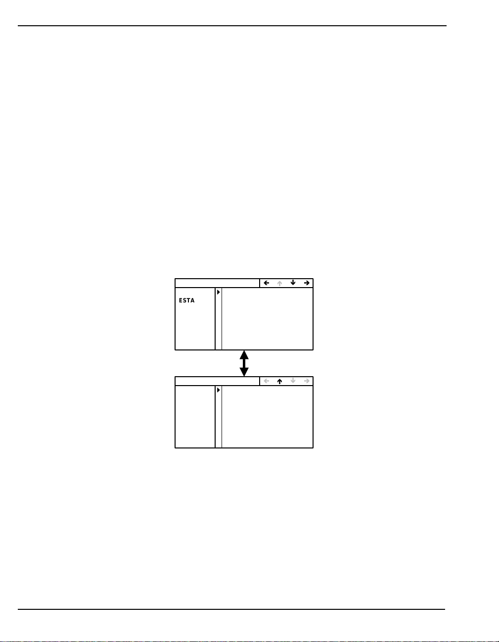
Chapter 5 VFD Menus
• LON: The current longitude in degrees, minutes, seconds and decimal
seconds to 4 decimal places.
• HEIGHT: The current mean sea level (MSL) height in meters to 3
decimal places.
• # SATS: The number of GPS satellites currently being tracked.
• MPC RECEIVER INFO
• SERIAL #: The GPSCard serial number.
• VERSION: The GPSCard firmware version.
• MODEL: The GPSCard model.
• UI VER: Shows the current version of the VFD user interface software.
5.2.2 Connect
The CONNECT function menu allows you to view the GPSCard’s current connection status with
three other devices. Figure 38 shows the MPC CONNECT MENU screen.
.
MPC CONNECT MENU
ENET
ESTATUS
MODEM
MSTATUS
DIRECT CONNECT:NO
DSTATUS
CONNECTED
198.161.68.216
CONNECT:NO
000.000.000.000
000.000.000.000
ÌÍÏÎ
MPC SHUTDOWN TYPE
EXECUTE
TYPE:REBOOT
ÌÍÏÎ
Figure 38: MPC Connect Menu
As seen in Figure 38, there are two Connect functionality menu s:
• MPC CONNECT MENU
• ENET: ‘NO’ or a connection status message depending on whether there
is or is not respectively a connection to the internet. If there is a status
message the IP address will also appear on the next row.
• ESTATUS: The IP address of the ethernet connection.
The ENET and ESTATUS rows are updated every 60 seconds unless a row is being
edited. The 60 second refresh will continue once the editing has stopped.
44 MPC User Manual Rev 0D
Page 45

VFD Menus Chapter 5
• MODEM: CONNECT: YES or NO depending on whether there is or is
not respectively a connection via the modem card.
• MST ATUS: The IP address of the mod em connection or a status mess age.
• DIRECT: CONNECT: YES or NO depending on whether there is or is
not respectively a connection via the serial port.
• DSTATUS: The IP address of the direct connection or a status message.
The MSTATUS and DSTATUS rows are refreshed when the Remote Access Service (RAS)
calls back
.
• MPC SHUTDOWN TYPE
• EXECUTE: Choose either ‘REBOOT’ or ‘POWERDOWN’ in the TYPE
data display. Press the <ESC> key to do neither and return to the last
menu. Choosing REBOOT will cause the MPC to reboot. Choosin g
POWERDOWN will power down the internal emb edded PC. The keypad
will be unusable again until the power switch is turned off, then on, and
the VFD is visible again.
* The MPC is designed for continuous operation. However, if you need to power down the unit, it
is recommended that you always use the MPC Shutdown Type menu, see above. Then give the
internal operating system a few minutes to flush its cache buffers to the hard drive, and turn off
the power at the power switch.
5.2.3 Configure Client
The CONFIG CLIENT menu allows you to enter information about the security rights for individuals
using the system. An example may be seen in Figure 39.
CONFIG CLIENT
USRNAME
PASSWRD
ADMIN
LOGGING
FTP
STATUS
SUBMIT INFO:NO
ABCDEFG
TUVWXYZ
PRIV:NO
CONTROL:NO
ACCESS:NO
VIEW:NO
Figure 39: Config Client Menus
It is only necessary to use the VFD menu the first time the MPC is used, usually by any Ad ministrator
with full privileges. User information can be added/edited using the Modulated Precision Clock
website. See also Section 6.1.2.7, Set Up Users on Page 65.
The CONFIG CLIENT menu contains the following information:
• CONFIG CLIENT
• USRNAME: A user ID in the form of a user name (8 characters
MPC User Manual Rev 0D 45
ÌÍÏÎ
Page 46

Chapter 5 VFD Menus
maximum). The MPC allows multiple users. Example of clients may be
the administrator who has all privi leges, the use rs wh o have some bu t not
all privileges, and guests who have little or no privileges.
• PASSWRD: A password for the above user (8 characters maximum).
• ADMIN: ‘YES’ or ‘NO’ depending on whether this user has or has not
respectively system privileges.
• LOGGING: ‘YES’ or ‘ NO’ depend ing on w hether this user has o r has no t
respectively the right to control logging.
• FTP: ‘YES’ or ‘NO’ depending on whether this user has or has not
respectively access to the MPC’s File Transfer-Protocol (FTP) service.
• STATU S: ‘YES’ or ‘NO’ depending on whether this user has or has not
respectively the right to view the MPC SYSTEM STATUS pages via the
Modulated Precision Clock website, see Chapter 6 starting on Page 49.
See also Status on Page 42.
• SUBMIT: Toggling to YES, and then pushing the <Enter> ke y, submits
the username, password and privileges to the appropriated configuration
files on the web server.
5.2.4 Configure Ethernet
The CONFIG ETHERNET menu allows yo u t o co nfigure the ethernet or internet connection with the
MPC. Figure 39 shows the CONFIG ETHERNET menu.
CONFIG ETHERNET
SOURCE AUTO IP:NO
IP ADDR
SUBNET
GATEWAY
COMPUTER PAT-TEST4
Figure 40: Config Ethernet Menu
• CONFIG ETHERNET
• SOURCE: ‘YES’ or ‘NO’ depending on whether or not respectively the
IP address is assigned automatically via a Dynamic Host Configura t ion
Protocol (DHCP) server on the local network (intranet). If AUTO IP is
changed to ‘YES’, then the IP, SUBNET and GATEWAY rows will be
assigned automatically upon activation and anything in the IP ADDR row
will be deleted.
• IP ADDR: The internet protocol (IP) address.
• SUBNET: The address of the system of interconnections within the
communications system that allows the components to communicate
000.000.000.000
000.000.000.000
000.000.000.000
ÌÍÏÎ
46 MPC User Manual Rev 0D
Page 47
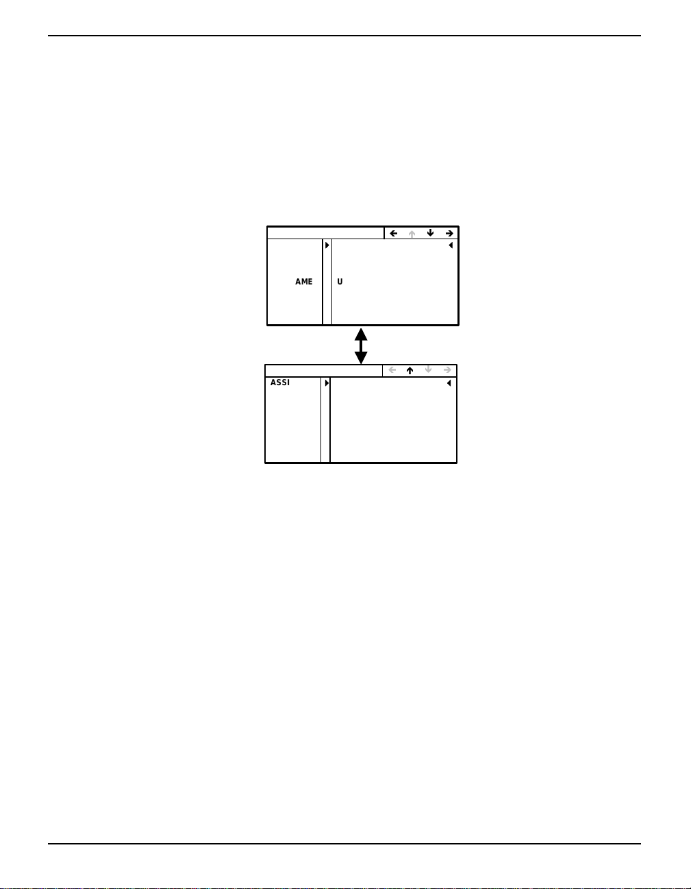
VFD Menus Chapter 5
directly with each other.
• GATEWAY: The address of the device that will transfer messages out of
the local network to the internet.
• COMPUTER: Give your MPC a network name (8 characters maximum).
5.2.5 Configure Modem
The CONFIG MODEM functionality group allows you to configure the internal modem connection
with the MPC. Figure 41 on Page 47 shows the CONFIG MODEM menus.
CONFIG MODEM
PHONE
PC COM
PROTO
USRNAME USERNAME4
PASSWRD PASSWORD4
SOURCE AUTO IP:NO
IP ADDR 000.000.000.000
CFG MODEM HOST
ASSIGN ASSIGN IP:N O
IP START
IP STOP
19002446262
57600 8 NONE 1 N
TYPE:PPP
000.000.000.000
000.000.000.000
ÌÍÏÎ
ÌÍÏÎ
Figure 41: Config Modem Menus
As seen from Figure 41, there are two CONFIG MODEM menus. One is for a client connection, see
also Section 4.2.2, Modem or Direct Connect (PPP) Client on Page 26, and the other is for a host
connection:
• CONFIG MODEM (Client)
• PHONE: The phone number of the service that the MPC is to call.
• PC COM: The communication parameters for the MODEM port.
• PROTO: The network protocol . The two choices are Point-to-Point (PPP)
or Serial Line Internet (SLIP) Protocol.
• USRNAME: The MPC’s client user name on the remote network.
• PASSWRD: The password for the above client.
• SOURCE: ‘YES’ or ‘NO’ depending on whether or not respectively the
IP address is assigned automatically by the host computer. If AUTO IP is
changed to ‘YES’, then the IP row will not be editable and anything in
the IP ADDR row will be deleted.
• IP ADDR: The internet protocol (IP) address.
MPC User Manual Rev 0D 47
Page 48

Chapter 5 VFD Menus
• CFG MODEM HOST
The MPC modem is preconfigured for auto-answering as a host. It will issue an IP
address in the range 1 92 .160 .20 0 to 192.160.215, and est abl is h a PPP connection to
the client. The client must use an Administrator username and password or set up a
user, see also Section 5.2.3, Configure Client on Page 45.
• ASSIGN: ‘YES’ or ‘NO’ depending on whether or not respectively the IP
start and stop addresses are assigned automatically. If ASSIGN is
changed to ‘YES’, then the IP START and IP STOP rows will not be
editable.
• IP START: Start of address space that the MPC will use to issue
addresses.
• IP STOP: End of address space.
5.2.6 Configure Direct (PPP)
The CONFIG DIRECT menu allows you to configure the connection with a host computer that is
connected directly to the MPC via an RS232 cable. Figure 42 shows the CONFIG DIRECT menu.
CONFIG DIRECT
MPC
PC COM
PROTO TYPE:PPP
USRNAME
PASSWRD
SOURCE AUTO IP:NO
IP ADDR 000.000.000.000
Figure 42: Config Direct
• CONFIG DIRECT
• MPC: Shows if the MPC is functioning as a client.
• PC COM: The communication parameters for the PPP port.
• PROTO: The network protocol . The two choices are Point-to-Point (PPP)
or Serial Line Internet (SLIP) Protocol.
• USRNAME: The user name that the MPC will use to ‘sign on’ to the host
computer.
• PASSWRD: The password for the above user.
• SOURCE: ‘YES’ or ‘NO’ depending on whether or not respectively the
IP address is updated automatically. If AUTO IP is changed to ‘YES’,
then the IP row will not be editable and anything in the IP ADDR row
will be deleted.
CLIENT
Ì ÍÏÎ
115200 8NONE1 N
USERNAME5
PASSWORD5
• IP ADDR: The internet protocol (IP) address.
48 MPC User Manual Rev 0D
Page 49
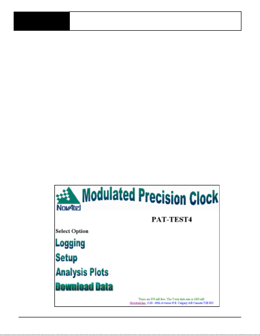
Chapter 6 Software Programs
The MPC software for the Euro4 GPSCard and the VFD are already installed.
The Modulated Precision Clock website is accessible on a PC via an internet connection. It is your
source for MPC setup, logging, system summaries and analysis plots. Details are given in Section 6.1,
Modulated Precis i on Clock Website starting below.
Please see Section 6.2, MPC Firmware Upgrades & Updates starting on Page 75 for a description on
how your MPC is upgraded/updated via the web. See also Customer Service on Page 10.
6.1 Modulated Precision Clock Website
To access the Modulated Precision Clock home page, use the IP address given by your internet
provider, as displayed by the VFD or provided by your Network Administrator, to use as a URL for
your MPC receiver using a PC. The following is a fictional example:
http://123.123.123.123/
Your Network Administrator may wish to provide you with a “STATIC” IP location on your internal
network (intranet) and associate this IP address with a name, for example “MPC1”, in your Domain
Name Server (DNS). In this case, you would access your MPC’s web page via the URL:
http://mpc1/
See also the Connect and Config menu sections of Chapter 5, VFD Menus starting on Page 44, and
Section 4.2, Configuring the Network on Page 25, for information on configuring your MPC and
connecting to the internet using the VFD menus.
Figure 43: Modulated Precision Clock Home Page
MPC User Manual Rev 0D 49
Page 50
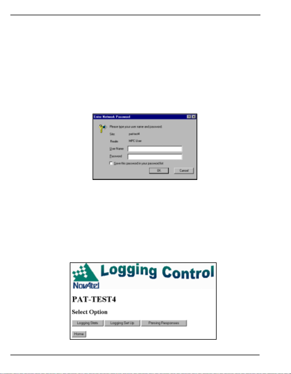
Chapter 6 Software Programs
As seen from Figure 43 on Page 49, there are four options in the Modulated Precision Clock home
page:
Logging, see Section 6.1.1, Logging below
Setup, see Section 6.1.2, Setup Configuration on Page 55
Analysis Plots, see Section 6.1.3, Analysis Plots on Page 67
Download Data, see Section 6.1.4, Download Data on Page 72
Once you are on the Modulated Precision Clock web page, you can type in your user ID and
password, and click on the OK button to log in. Your MPC administrator is responsible for updating
users and passwords, please see Section 5.2.3, Configure Client on Page 45. An example of the
Modulated Precision Clock website login is shown in Figure 44 below.
Figure 44: MPC Website Login
You will then be able to view the Home page, as seen in Figure 43 on Page 49, and be able to click on
the links that you have access to.
6.1.1 Logging
Logs and commands can be set up and logging statistics can be viewed from the Logging Control
page. Select one of above options by clic king on the appropri ate button, or retur n to the Home page by
clicking on the Home button, see Figure 45.
Figure 45: Logging Control
50 MPC User Manual Rev 0D
Page 51
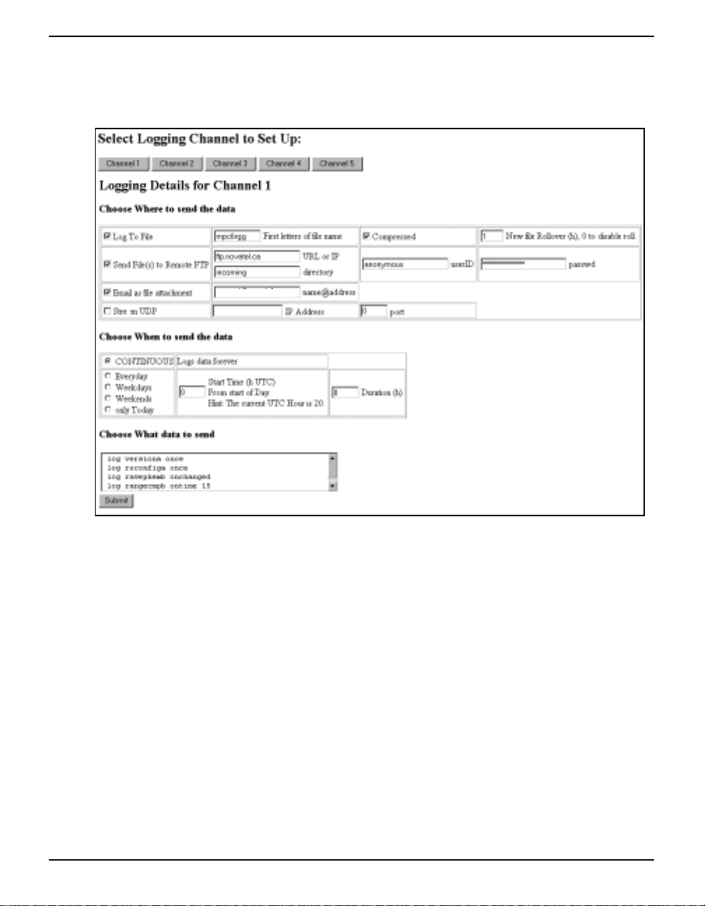
Software Programs Chapter 6
6.1.1.1 Logging Setup
You can set up logs for up to 5 channels on your MPC. Select a channel and click on its button, see
Figure 46.
support@novatel.ca
a
Figure 46: Set Up Logging
First, choose where to send your data.
If you select Log to File, give your schedule for that channel a name in the First Characters of File
Name field. If this field is left blank, the schedule for that channel will be ignored. The name you give
this schedule will form part of the filename written to the hard disk in the MPC. The file name will
take the form:
FIRSTCHARSyymmddhh
where FIRSTCHARS is the name you gave to the schedule in the First Characters field, yy, mm and
dd are the year, month and date respectively and are generated from the MPC’s internal Time at the
nearest hour (hh on a 24 hour clock) on every hour that is divisible by the Rollover amount.
Click in the Compressed check box if you wish your file to be compressed.
Enter the amount of rollover time (in hours) in the Rollover field. If you enter 0, roll over is disabled.
You may also send your data to a Remote FTP site, as an e-mail file attachment, and a Stream User
Datagram Protocol (UDP) by clicking in their respective check boxes and entering appropriate
information in their required fields. The UDP message format is shown in Table 2 on Page 52.
MPC User Manual Rev 0D 51
Page 52

Chapter 6 Software Programs
T able 2: UDP Message Format
Description Offset Size Type Value
Sync1 0 1 uchar 0xAA
Sync2 1 1 uchar 0x44
Sync3 2 1 uchar 0x16
MPCID 3 4 ulong 0....MAX_ULONG (unique MPC station ID,
Hop Count 7 1 uc ha r 0...255 (t he number of times the UDP was
Message Length 8 2 usho rt 0...65535 ( size of the im bedded messag e but not
Message 10 <65535 binary NovAtel OEM4 ASCII or binary message
see Section 6.1.2.1, Set MPC Name on Page 56)
forwarded betwee n No vAtel relay stations)
including the header )
Next, choose when to send t he data or set up a schedule. Choosing CONTINUOUS logs your data
continuously. It will start a new file every hour that is divisible by the Rollover amount in the Choose
Where section. The other choices are Everyday, Weekdays, Weekends, and Only Today. If you select
any of these choices, you can then enter a UTC start time in hours in the Start Time field and the
amount of hours to continue logging in the Duration field. The start time refers to the start of the day.
Finally , type in the logs yo u want in this sched ule in the Choose What section’s edit box. Ensure each
log request is on a new line. For more information on the available logs for the OEM4 family of
receivers, please refer to Volume 2 of the OEM4 Users’ Guide.
Click on the Submit button when you have completed your schedule list. The Command/Response
Summary for your schedule will appear. An example is shown in Figure 47 on Page 53. If you
misspell any of the logs, the Command/Response window will contain syntax errors for you to check.
Click on the Cancel button to return you to the main Logging Control window (Figure 45 on
Page 50).
Filename Examples:
If it is 3 p.m. and you request CONTINUOUS in the Choose When section, and 6 in the Choose
Where section’s Rollov er f ield, hh will be 12 and will roll over at 6 p. m. (only 3 hours later) when hh
will be 18. The next rollover will be at midnight (6 hours later) when hh will be 00.
Here are some filename examples starting at 5:45 p.m ., the First Letters of File Name were entered as
‘range’, with a rollover of 6 hours:
range02011712.bin range02011718.bin range02011700.bin
range02011806.bin range02011812.bin
* 1. The MPC internal time is Coordinated Universal Time (UTC) and may vary by several hours
from your local time.
2. If you have any difficulty with sending files, for instance e-mail or external ftp, NovAtel
Customer Service may request any G PS Ser ver.log or LoggerServer.log files from your MPC’s
ftp site or root directory.
52 MPC User Manual Rev 0D
Page 53
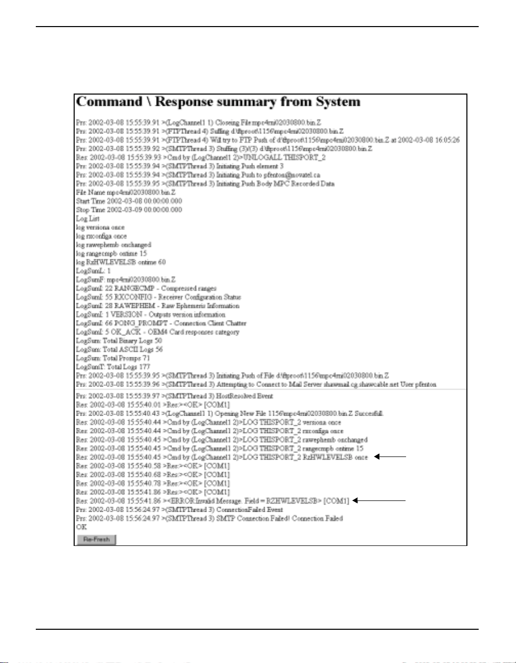
Software Programs Chapter 6
6.1.1.2 Parsing Responses
Click on the Parsin g Responses button to go t o the C ommand/Response System Su mmary w in dow as
seen in Figure 47.
Misspelling
Error Message
Figure 47: Command/Response System Summary
MPC User Manual Rev 0D 53
Page 54

Chapter 6 Software Programs
There are three types of output in the summary:
Cmd A log summary in the form:
Cmd: YYYY-MM-DD hh:mm:ss.ss>LOG THISPORT_c log
where
YYYY is the calendar year (e.g. 2002)
MM is the calendar month (01-12)
DD is the calendar date (01-31)
hh.mm.ss.ss is the time in hours (00-23), minutes (00-59) and
decimal seconds (00.00-59.99) in GMT
LOG or UNLOG
c is the channel number
log is the LOG command if applicable (Please refer to Volume 2 of
the OEM4 Users’ Guide for possible formats of the LOG
command and for a listing of the available logs.)
Res An OEM4 respon se summary in the form:
Res: YYYY-MM-DD hh:mm:ss.ss> response
where
YYYY-MM-DD hh:mm:ss.ss are as they are in Cmd above
response is a message, or a response to a log command
Notice in Figure 47 on Page 53 that an RXHWLEVELS log was misspelled in the Logging Control window and is highlighted here. The response, in the form of an error message, is also highlighted in Figure 47.
Prs Is a parsing response such as an MPC system response in the form:
Prs: start >stop (c) action
where
start time is the time, in GMT, that the parse response started in the
form YYYY-MM-DD hh:mm:ss.ss as described in Cmd above
stop time is the time, in GMT, that the parse response ended in the
form YYYY-MM-DD hh:mm:ss.ss as described in Cmd above
c is the channel number
action is an MPC file or system action
The Home button will return you to the Modulated Precision Clock home page (Figur e43 on
Page 49).
54 MPC User Manual Rev 0D
Page 55
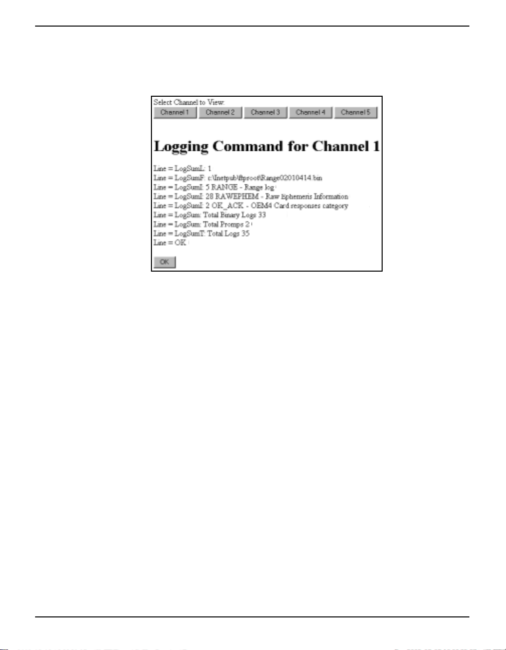
Software Programs Chapter 6
6.1.1.3 Logging Stats
In the Logging Control window, click on the Logging Stats button to bring you to the Logging
Statistics page. An example is shown in Figure 48.
Figure 48: Logging Statistics
Choose a Channel by clicking on its button. Log summaries are shown line by line. The following
definitions apply:
LogSumL: Specifies the channel number
Log SumF: Specifies the file name and location on the MPC
LogSumI: A log, command or message that has occurred as a result of the
current channel’s schedule. The log name is preceded by the number of times it has been received and recorded in the file. It is then
followed by a short defi nition.
LogSum: On its own, LogSum gives a count of the Total Binary Logs, the
Total ASCII logs or the Tot al Prom pts (or mes sages) that ha ve occurred as a result of the current channel’s schedule.
LogSumT: Specifies the tot al number of logs , command and prompt s based on
the LogSum lines above.
Click on the OK button to return you to the main Logging Control window (Figure 45 on Page 50).
6.1.2 Setup Configuration
The Setup Configuration window allows you to configure your internet connection, modify the name
you give to your MPC, check the receiver conf ig uratio n and recon figure your MPC using commands,
adjust services, upload data, and upgrade/update the MPC firmware. The Setup Configuration
window can be seen in Figure 49.
MPC User Manual Rev 0D 55
Page 56
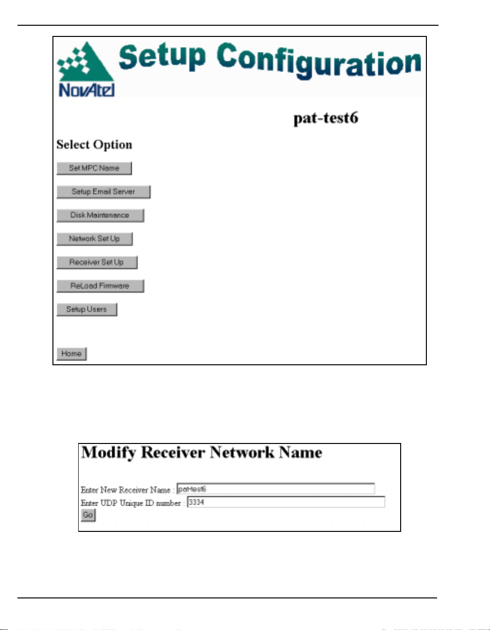
Chapter 6 Software Programs
Figure 49: Set Up Configuration
6.1.2.1 Set MPC Name
Click on the General Setup button for the Modify Receiver Parameters window to appear as seen in
Figure 50 on Page 56.
Figure 50: General Receiver Setup
The Receiver Name is a name you give your MPC that is meaningful to you. This name will also
appear in the main Modulated Pr ecision Cl ock windows (Logging , System Summary Res ponse, Set up
and Analysis Plots). The Enter UDP Unique ID number field allows you to give your MPC a unique
56 MPC User Manual Rev 0D
Page 57
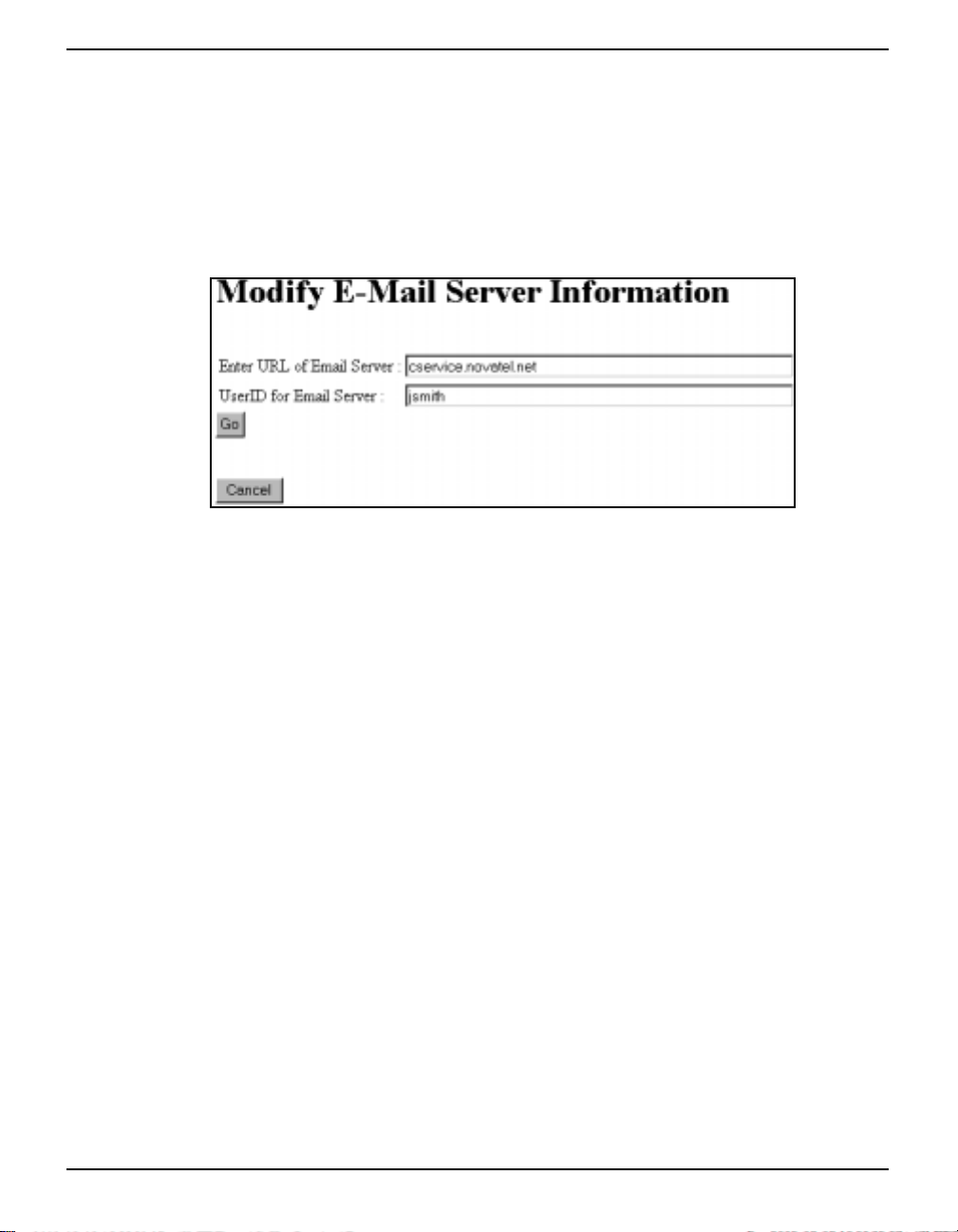
Software Programs Chapter 6
ID number which is imbedded in the UDP data str eam (if used), see Sectio n 6.1.1 .1, Lo ggin g Setu p on
Page 51. It uniquely identifies the messages as originating from your MPC. Click on the Go button to
save your changes.
6.1.2.2 Set Up E-Mail Server
If you intend to transfer collected data files via an e-mail attachment, you must set up e-mail server
information through The Set Up E-Mail Server page as seen in Figure 51.
Figure 51: Set Up E-Mail Server
Type in the URL of the e-mail server in the Enter URL of Email Server field. The Enter UserID For
Email Server field allows you to type in your e-mail server user identification. Click on the Go button
to save your changes, or on Cancel to disregard your changes, and return you to the main Setup
Configuration page.
6.1.2.3 Disk Maintenance
In the Setup Auto Disk Cleanup section of the Disk Maintenance window, see Figure 52 on Page 58,
select the type of cleanup to allow. The choices are:
• Disable auto disk cleanup Data logging will stop when the disk space reaches the
minimum set in the Minimum Free Disk Space (Full Level)
MB edit field.
• Delete Old Files Enter the maximum age of files to keep in days. Files older
than this will be deleted.
• Delete the Oldest Files when Full Enter the minimum disk space to be left. This is done by
replacing old files with new files that go over the minimum.
MPC User Manual Rev 0D 57
Page 58
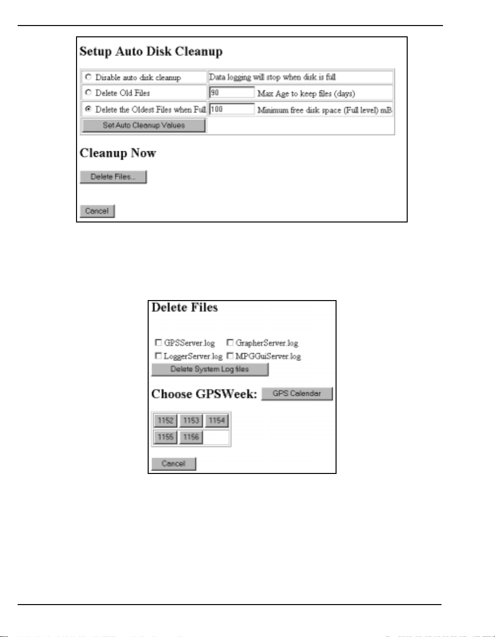
Chapter 6 Software Programs
Figure 52: Disk Maintenance
Click on the Set Auto Cleanup Values button to save your selection, or click on the Cancel button to
disregard your changes and return you to the main Configuration Setup window. Click on the Delete
Files button and the Delete Files window will appear as seen in Figure 53.
Figure 53: Delete Files
The *.log checkboxes in the top half of the dialog allow you to select log files for deletion. These log
files contain messages and information on different parts of your MPC as seen below:
GPSServer GPSCard
GrapherServer MPC Plots
LoggerServer Logging Setup and Logged Files
MPCGuiServer VFD Panel
These types of files are on the MPC’s ftp site or root directory and may be requested by Customer
58 MPC User Manual Rev 0D
Page 59
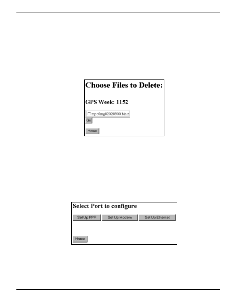
Software Programs Chapter 6
Service if you have any MPC questions or problems.
Files that become too large can be selected here and then deleted by clicking on the Delete System
Log Files button.
The bottom half of the Delete Files dialog allows you to choose a week number by clicking on one of
the available GPS weeks button. If you need to refer to a calendar of GPS weeks, click on the GPS
Calendar button firs t. A description of the GPS C al e ndar i s giv e n in S ectio n 6 . 1. 4, Download Data on
Page 72.
When you have clicked on a GPS week’s button, a dialog will appear showing the files available for
deletion, see Figure 54.
Figure 54: Choose Files to Delete
Select a file for deletion and click in its check box. Choose more than one file if applicable and click
on the GO button to delete them or click on the Home button to return to the main Setup
Configuration page and abandon deletion.
6.1.2.4 Network Setup
In the Setup Configuration window, click on the Network Setup button. The Select Port to Configure
window appears as seen in Figure 55 on Page 59.
Figure 55: Network Setup
From this page you can choose the Set Up button for your internet connection. The choices are PPP,
Modem and Ethernet.
MPC User Manual Rev 0D 59
Page 60
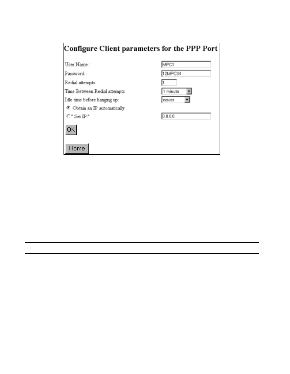
Chapter 6 Software Programs
CONFIGURE PPP PORT
An example of the Configure PPP Port window i s shown in Figure 56.
Figure 56: Configure PPP Port
First enter the user name and password the MPC will use to ‘connect’ to the PPP host in the User
Name and Password fields. Then enter th e number of redial attempts you would like the MPC to make
and choose a length of time between these attempts.
Choose how long, or never, to wait while the connection is idle before the MPC should hang up.
Select to enter the IP address for the direct connection in the Set IP field, or select Obtain an IP
Automatically for the IP address to be assigned automatically.
Click on the OK button to save your changes or click on the Home button to cancel the settings return
you to the Modulated Precision Clock home page.
* Some of these parameters can also be adjusted via the VFD panel on the MPC.
60 MPC User Manual Rev 0D
Page 61
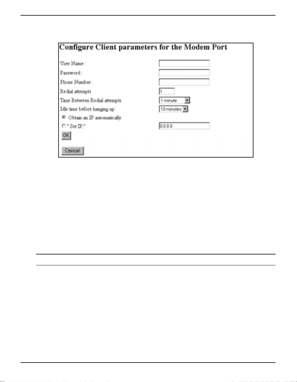
Software Programs Chapter 6
CONFIGURE MODEM PORT
An example of the Configure Modem Port window is shown in Figure 57.
MPC1
12MPC34
2954500
Figure 57: Configure Modem Port
First enter the user name and password the MPC will use to ‘connect’ to the PPP host in the User
Name and Password fields. Then enter the phone number that the modem is to call out on to make a
connection with the host or internet service provider. Enter the number of redial attempts you would
like the modem to make and choose a length of time between these attempts.
Choose how long, or never, to wait while the connection is idle before the modem should hang up.
Select to enter the IP address for the modem connection in the Set IP field, or select Obtain an IP
Automatically for the IP address to be assigned automatically.
Click on the OK button to save your changes or click on the Home button to cancel the settings return
you to the Modulated Precision Clock home page.
* Some of these parameters can also be adjusted via the VFD panel on the MPC.
MPC User Manual Rev 0D 61
Page 62
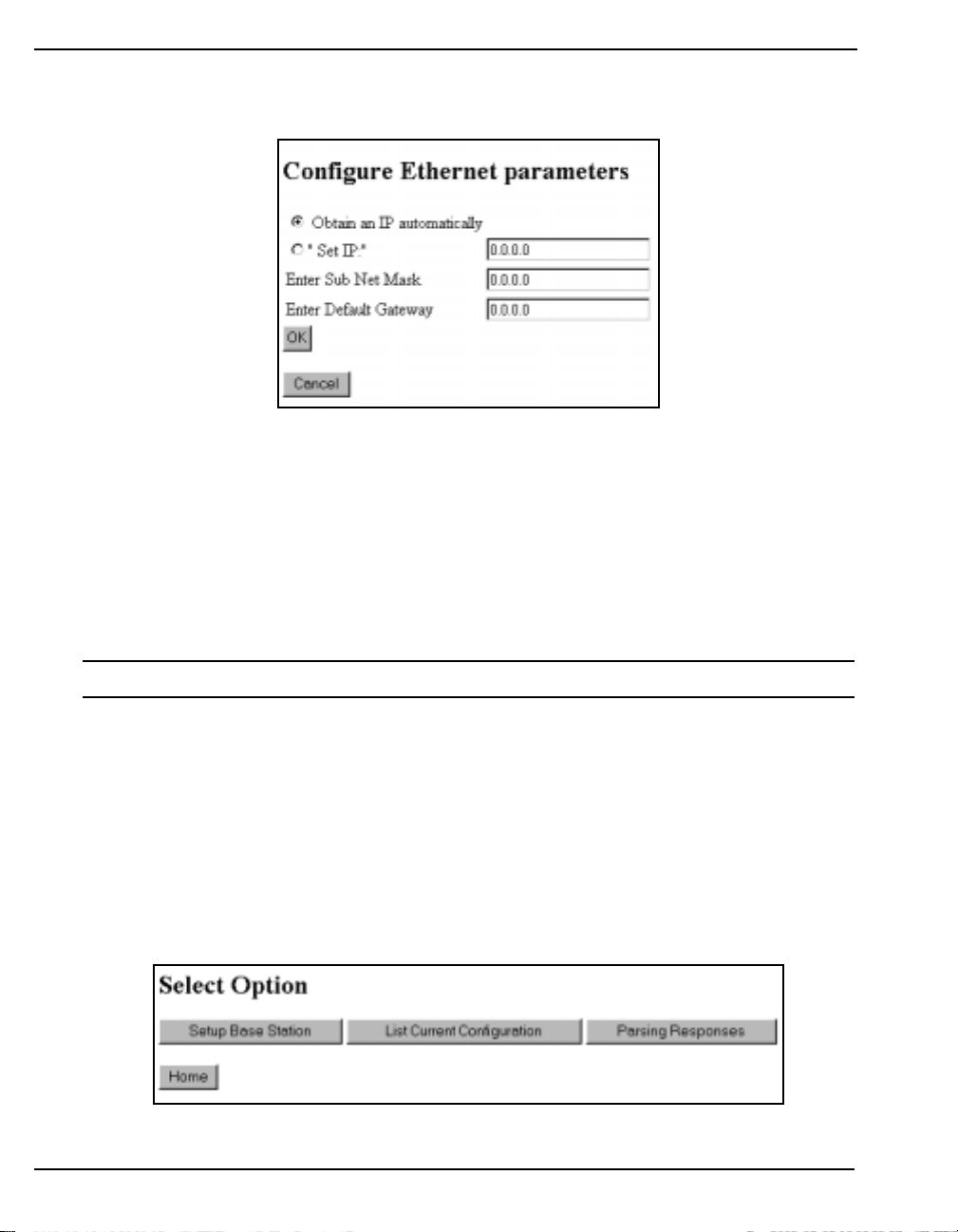
Chapter 6 Software Programs
CONFIGURE ETHERNET PORT
An example of the Configure Ethernet Port window is shown in Figure 58.
Figure 58: Configure Ethernet Port
Select whether to enter the IP address for the modem connection in the Set IP field, or select Obtain an
IP Automatically for the IP address to be assigned automatically.
If you selected the Set IP field, enter the address of the system of interconnections within the
communications system that allows the components to communicate directly with each other in the
Enter Sub Net Mask field. Enter the default gateway address in the Enter Default Gateway field.
Click on the OK button to save your changes, or click on the Cancel button to cancel the settings and
return you to the main Network Setup page.
* Some of these parameters can also be adjusted via the VFD panel on the MPC.
6.1.2.5 Receiver Setup
Click on the Receiver Setup button in the main Configuration Setup window to bring you to the
Receiver Setup window as seen in Figure 59. There are three options in this screen that are described
further in this section:
• Set Up Base Station
• List Current Config uration
• Parsing Responses
Figure 59: Receiver Setup
62 MPC User Manual Rev 0D
Page 63

Software Programs Chapter 6
SET UP BASE STATION
To set up your MPC as a base station, click on the Set Up Base Station button in the Receiver Setup
dialog, see Figure 59, to bring you to the List Current Configuration window where you can enter
GPS commands. See also List Current Configuration starting on Page 63.
To fix the position for your MPC base, enter the Latitude, Longitude and Height using the FIX
command. If you do not fix the base station position, the current position is computed by the MPC.
Use the Set Up Logging window to en ter t he RTCA, RTCM, or CMR messages that your base stat ion
will transmit. See also Section 6.1.1.1, Logging Setup on Page 51.
For more information on base station commands and logs, please refer to Volume 2 of the OEM4
Users’ Guide.
PARSING RESPONSES SETUP
The Parsing Responses page is also av ailab le th rou gh t he main Logg ing w indo w. See Section 6.1.1.2,
Parsing Responses on Page 53.
LIST CURRENT CONFIGURATION
The Set Up Logging screen, see Figure 46 on Page 51, is for setting up logs only. Use the List Current
Configuration button in the Receiver Setup dialog, see Figure 59 on Page 62, to bring you to the Rx
Config from GPS screen, shown in Figure 60 on Page 64, that will allow you to issue commands to
the internal Euro4 GPS receiver or simply check the current receiver configuration.
Once you have reviewed the MPC receiver’s current configuration, return to the Receiver Setup page
by clicking on the Home button, or add/edit a command by t yping it in the Ente r GPS Command field.
When you enter a command, ensure to type in its complete syntax if necessary. Only optional fields
may be omitted. For details on available commands, please refer to Volume 2 of the OEM4 Users’
Guide.
Click on the Send button to send your command to the MPC. The Command\Response System
Summary, see Figure 47 on Page 53 appears with your commanded added at the bottom. Click on the
Home button to return to the Receiver Setup page.
Click on the List Current Configuration button to check your new receiver configuration or to add/edit
another command.
Click on the Refresh button at the bottom of the Rx Config from GPS screen at any stage to refresh the
current configuration list.
WARNING: The Euro4 GPS receiver communicates with the MPC main processor via COM1. Do
not disturb the COM1 configuration or unexpected results may occur.
* COM3 on the Euro4 GPS receiver is connected to the DGPS port on the back of the MPC for
general GPS input/output.
MPC User Manual Rev 0D 63
Page 64
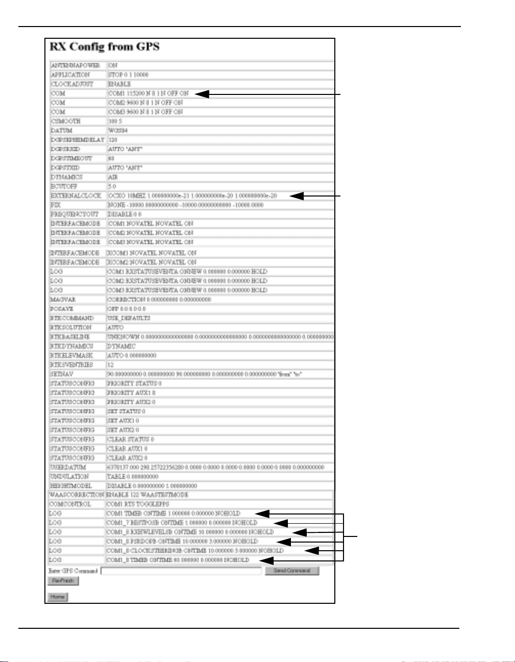
Chapter 6 Software Programs
Chapter 1
Used by MPC’ s int ernal Eu ro4
receiver - do not adjust!
Used by MPC’s internal 10
MHz OCXO - do not adjust!
MPC status messages to
COM1. They are used to
update screens and plots
- do not adjust!
Figure 60: Current Receiver Configuration
64 MPC User Manual Rev 0D
Page 65
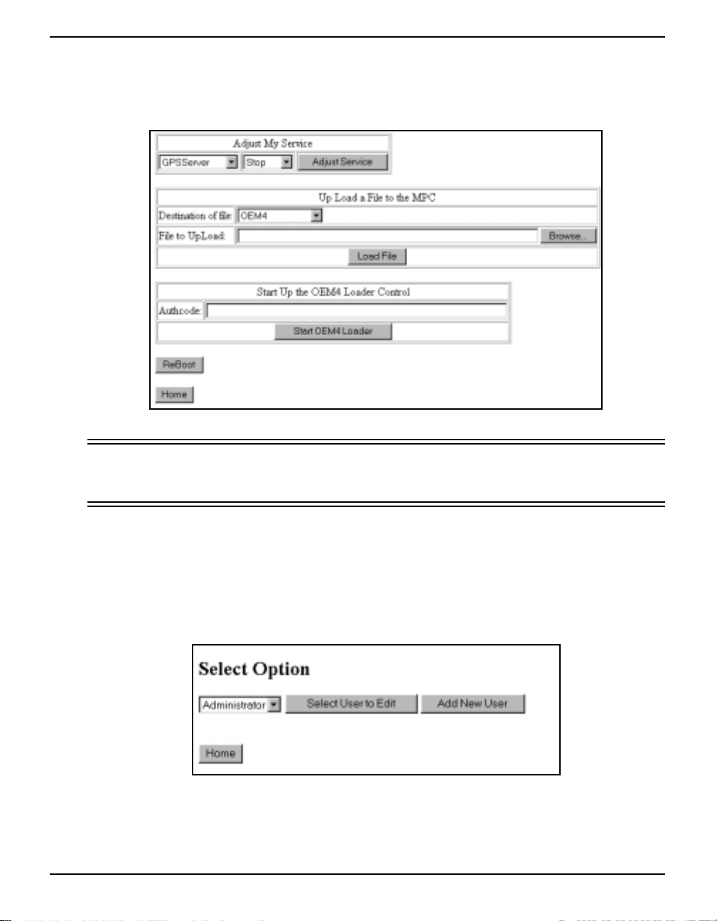
Software Programs Chapter 6
6.1.2.6 Reload Firmware
In the Setup Configurati on dialog, s ee Figure 49 on Page 56, click on the ReLoad Firmware button to
bring you to the screen shown in Figur e 61.
Figure 61: Reload Firmware
WARNING: The Reload Firmware page is intended for use by NovAtel Customer Service
personnel only. Incorrect commands on this page may result in th e MPC being
permanently disabled!
For more information on firmware or PC software upgrades/updates please see Section 6.2, MPC
Firmware Upgrades & Updates on Page 75.
6.1.2.7 Set Up Users
Click on the Set Up Users button in the main Configuration Setup window and the Set Up Users
window will appear as seen in Figure 62 on Page 65.
Figure 62: Set Up Users
Once you have selected a user from the list, you can either edit that user, or add a new user. These are
described in this section.
MPC User Manual Rev 0D 65
Page 66
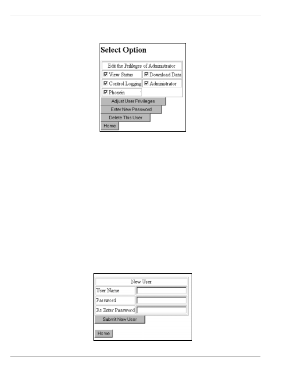
Chapter 6 Software Programs
SELECT USER TO EDIT
Click on the Edit button in the Set Up Users window and the Edit User window will appear as seen in
Figure 63.
Figure 63: Edit User
Check in the privileges check boxes that apply to the current user. The choices are:
• View Status The user can view the status pages on the website
• Download Data The user can download data from the MPC using the website
• Control Logging The user can use the Logging windows and control logging
• Phonein The user can phone in to the MPC via the modem connection
Click on the Adjust User Privileges button for the options to take effect.
Click on the Enter New Password button to change the password for the user.
To delete a user, click on the Delete This User button.
When you are done click on the Home button to return you to the main Set Up Users page.
ADD NEW USER
Click on the Add New User button in the Set Up Users window and the New User window will appear
as seen in Figure 64.
Figure 64: Add New User
66 MPC User Manual Rev 0D
Page 67
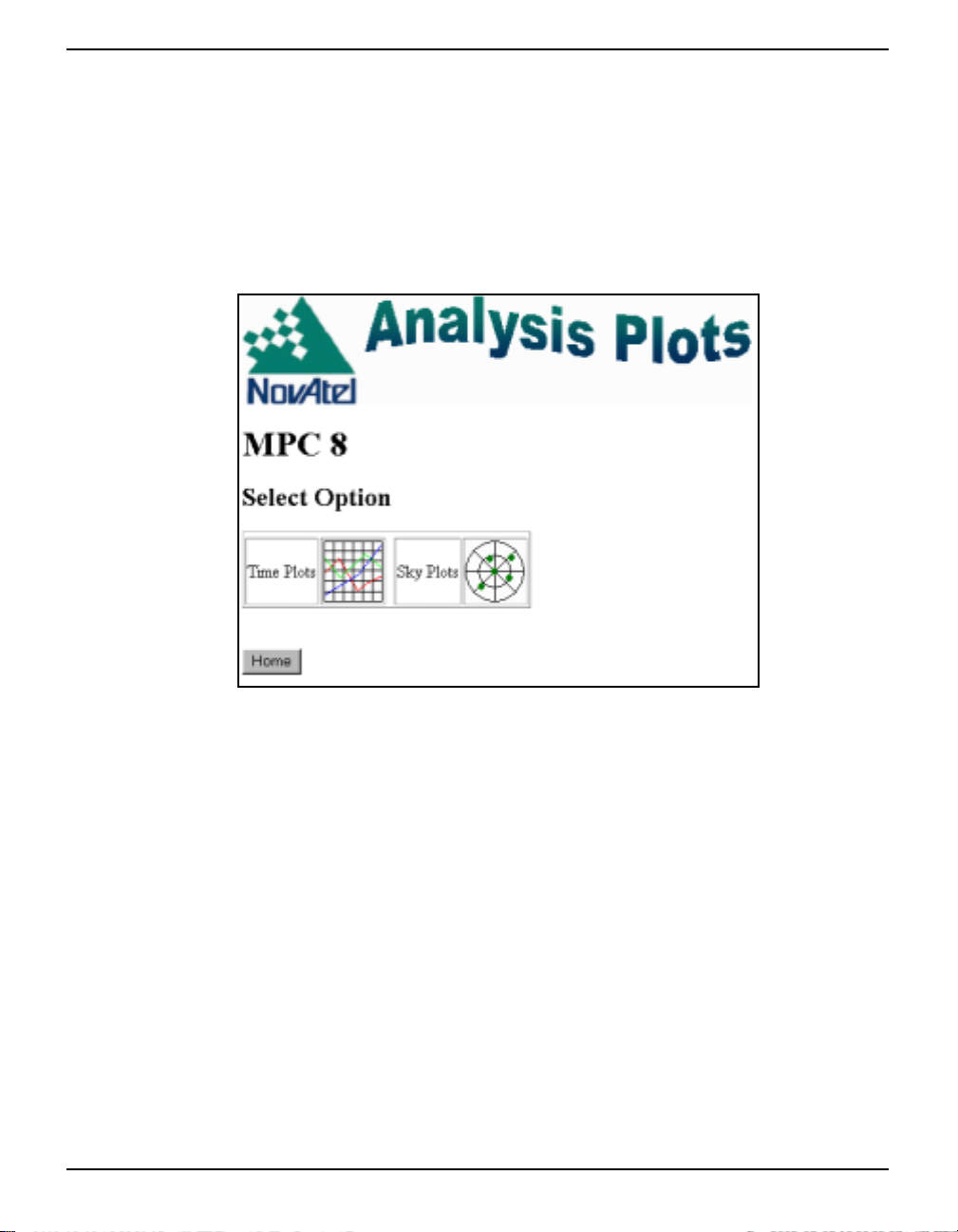
Software Programs Chapter 6
Enter a username and password for the new user. Then re-enter the password in the Re Enter Password
field to ensure you typed it in correctly.
Click on the Submit New User field to save the new user, or on the Home button to disregard your
changes and return to the main Set Up Users page.
6.1.3 Analysis Plots
The Analysis Plots Page gives you a choice of multiple plots in two formats. Icons of the plot formats
(Time Plots and Sky Plots) are shown in the Analysis Plots window as seen in Figure 65.
Figure 65: Select Analysis Plot Type
Each of the plots has a Home button. Click on the Home button to return you to the Modulated
Precision Clock website home page, or use your internet browse r’s back button t o take you bac k to the
plot that you last viewed.
6.1.3.1 Time Plots
When you click on the T i me Plots ico n in the Analys is Plots pa ge, a dialog ap pears as shown i n Figure
66 that allows you to select a time plot of your choice and the time period for the plot.
MPC User Manual Rev 0D 67
Page 68
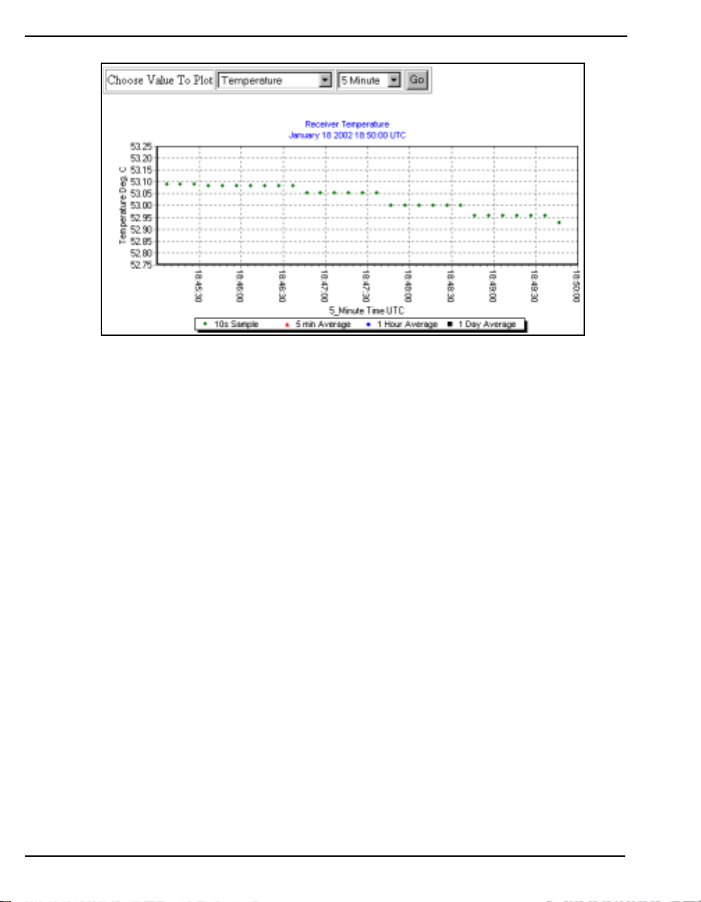
Chapter 6 Software Programs
Figure 66: Choose Value to Plot Against Time
The default plot shown is the Temperature Vs. Time plot over 5 minutes. Select a value to plot against
time in the Choose Value to Plot field. Your choices are:
• Temperature
• GDOP
• OEM4 Idle Time
• Number of Satellites
• Clock Error
• Clock Steering
Next choose the time period for your plot. The choices range from 5 minutes up to a maximum of 10
years.
Click on the GO button to gen erate the p lot. An ex ample of a Temperature Vs. Time plot ov er a 6 hour
time span is shown in Figure 67.
68 MPC User Manual Rev 0D
Page 69
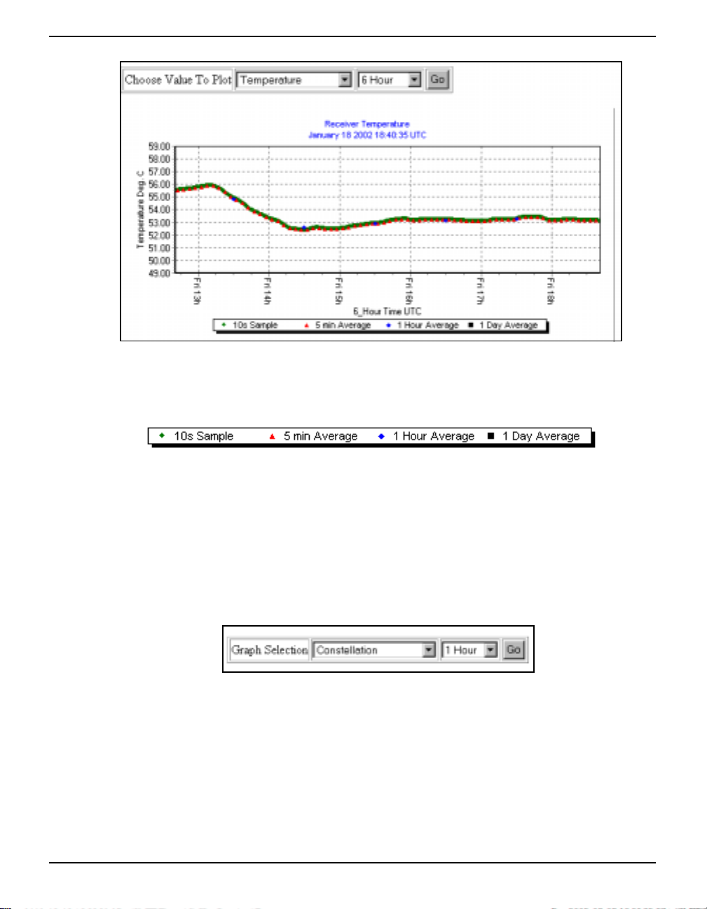
Software Programs Chapter 6
Figure 67: Time Plot Example
Figure 68 shows the key that is displayed with each plot. It is a key of how the points in the plot are
portrayed.
Figure 68: Time Plot Key
All plots are displayed in *.PNG format.
6.1.3.2 Sky Plots
When you click on the Sky Plots icon in the Analysis Plots screen, see Figure 65 on Page 67, a dialog
appears with fields that allows you to select a sky plot of your choice and the time period for the plot.
The fields are shown in Figure 69 below.
Figure 69: Choose Sky Plot
The default plot shown is the Constellation plot over 1 hour. Select a plot type in the Graph Selection
field. Your choices are:
• Constellation
• L1 Carrier to Noise Vs. Elevation
• L2 Carrier to Noise Vs. Elevation
• L1 Code Minus Carrier Vs. Elevation
• L2 Code Minus Carrier Vs. Elevation
MPC User Manual Rev 0D 69
Page 70
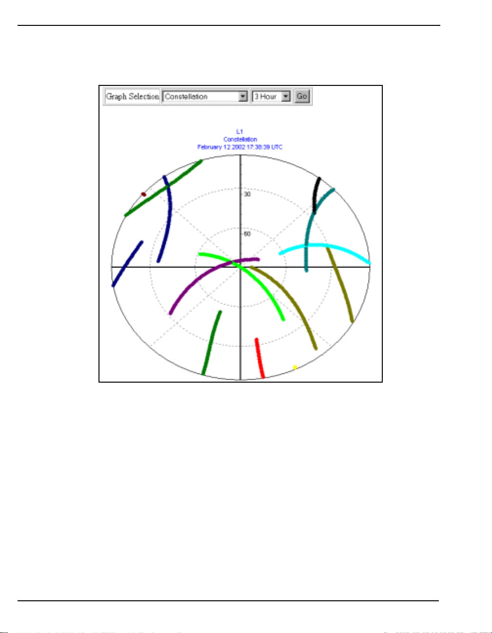
Chapter 6 Software Programs
Next choose the time period for your plo t. The choices ra nge from 1 ho ur up to a maximum of 7 day s.
Click on the GO button to generate the plot.
In the Constellation plots, each colour represents a satellite PRN. An example is shown in Figure 70.
Figure 70: Constellation Sky Plot
In the Carrier to Noise, and Code Minus Carrier, versus Elevation plots, each colour represents the
minimum, maximum and mean values of the data. A colour key will be shown on each plot to explain
the colours being displayed.
Examples are shown in Figures 71 and 72 on Page 71.
All plots are displayed in *.PNG format.
70 MPC User Manual Rev 0D
Page 71
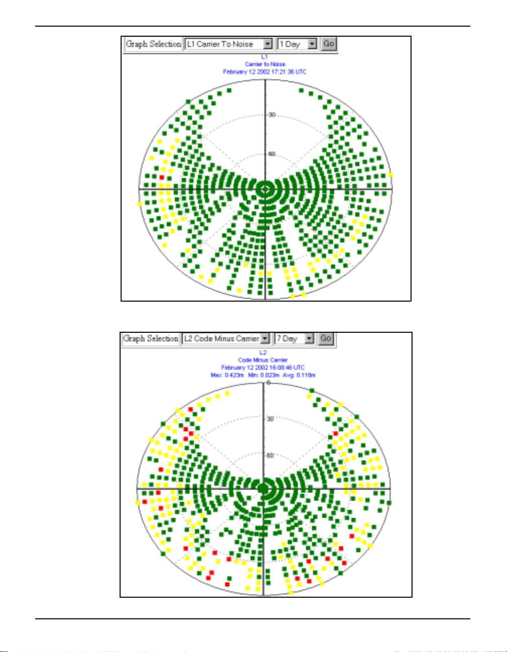
Software Programs Chapter 6
Figure 71: L1 Carrier to Noise Vs. Elevation
Figure 72: L2 Code Minus Carrier Vs. Elevation
MPC User Manual Rev 0D 71
Page 72
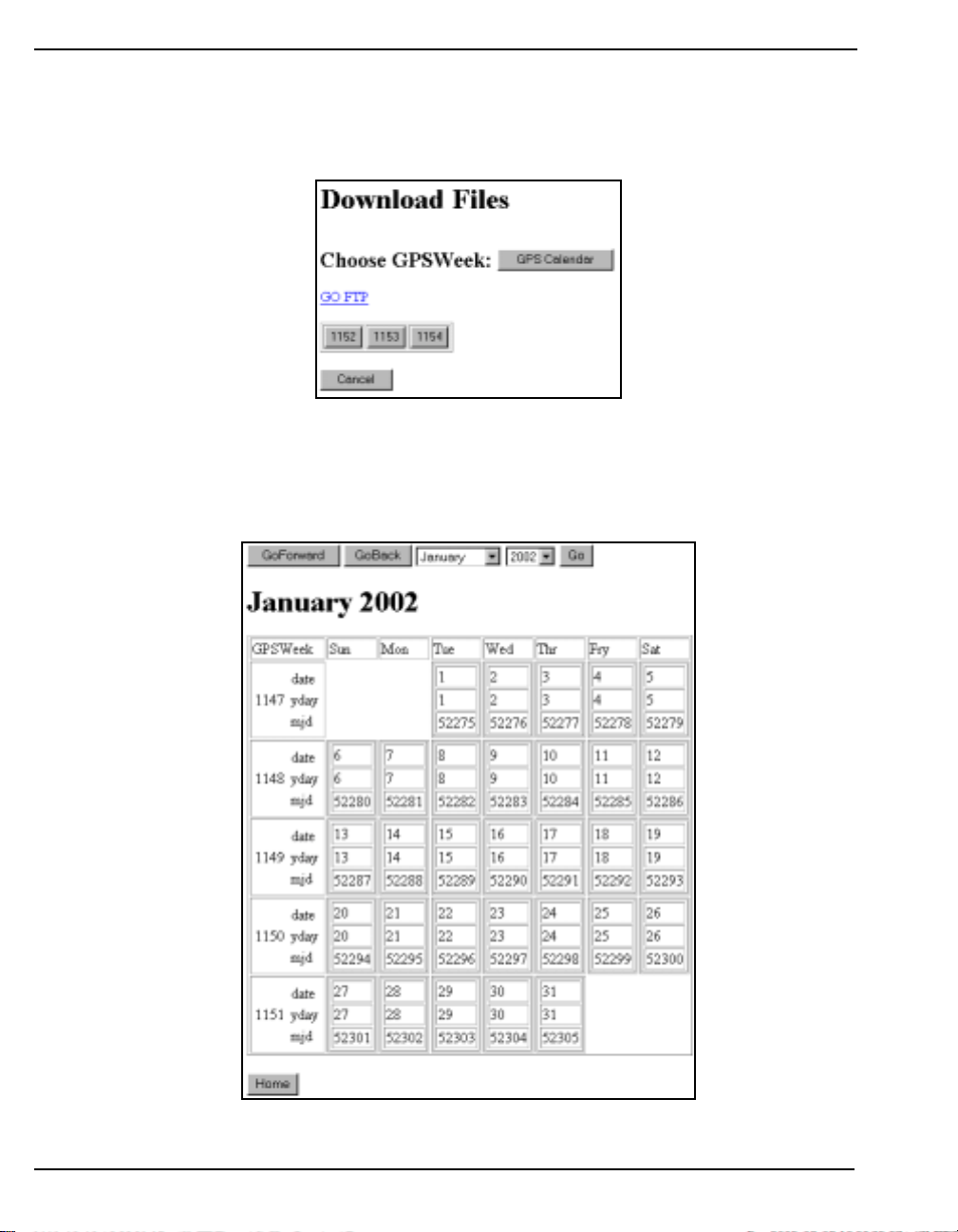
Chapter 6 Software Programs
6.1.4 Download Data
In the Logging Control window, click on the Download Data button. The Download Files window
appears as seen in Figure 73.
Figure 73: Download Data
You are shown a choice of GPS week buttons. You can first use the GPS Calendar button to check
which GPS week you are interested in. The GPS Calendar window can be seen in Figure 74 on
Page 72.
Figure 74: GPS Calendar
72 MPC User Manual Rev 0D
Page 73
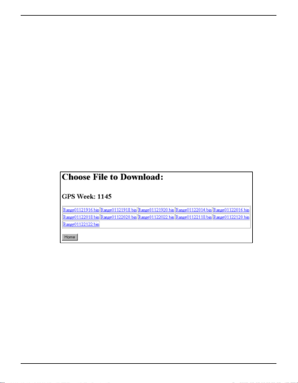
Software Programs Chapter 6
Each GPS week is shown in the far left of the screen. There are also three rows for each GPS week
that show:
date The regular calendar dates for the week
ydate Each corresponding number of days into the year for each day of
the week
mjd The Modified Julian Day (MJ F) is defined as t he Julian Day minus
2400000.5. For any date in the 20
th
and 21st centuries, the MJD
will be at most five decimal digits long. The Julian Period, an
interval of 7980 years, began at 12 noon, January 1, 4713 BC and
will end at 12 noon, January 1, 3268 AD.
You can go back or forward through the calendar months by using the Go Back and Go Forward
buttons. Alternatively you can select a calendar month and year from their respective drop down
boxes and then click on the Go button.
The Home button will return you to the Modulated Precision Clock home page (Figure43 on
Page 49) so if you have decided on a GPS week number , cli ck on your int ernet bro wser’ s back button
to return you to the Download Files window (Figure 73 on Page 72). From here you can now click on
the GPS week button of your choice. The Choose File to Download window appears as seen in
Figure 75.
Figure 75: Choose File to Download
Click on the link for the file you wish to download.
Click on the GO FTP link, see Figure 73 on Page 72, to go to the FTP address you specified in the
Logging Setup window’s Send File(s) to Remote FTP field. See also Section 6.1.1.1, Logging Setup
on Page 51.
Click on the OK button return to the Modulated Precision Clock home page. No downloading will
take place.
For a description of the format of the filenames, see the Set Up Logging section on Page 51. Choose a
filename and click on its link. A standard Windows download screen appears as seen in Figure 76 on
Page 74.
MPC User Manual Rev 0D 73
Page 74
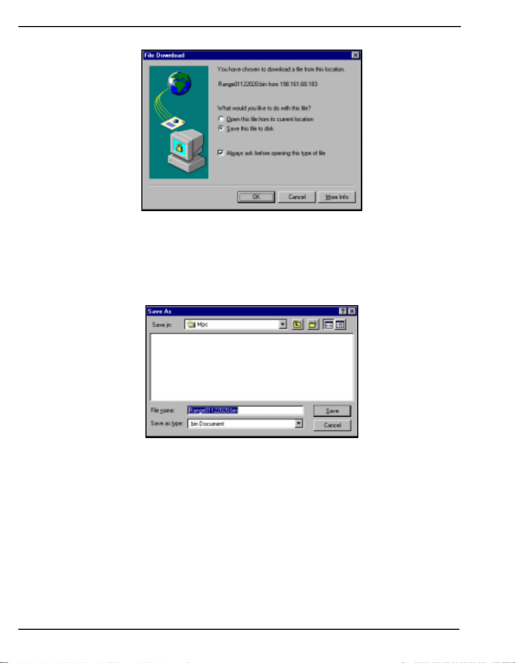
Chapter 6 Software Programs
Figure 76: Typical File Download Window
T o save th e file to d isk, choo se the Save Th is File to Disk fiel d. Cli ck on the OK b utton and a Sav e As
window appears (Figure 77) so that you can browse for a location for the file and save the file as a
different filename if you choose.
Figure 77: Save As
The Save As window is shown in Figure 77. Click on the Save button to save the file in your chosen
location.
When you have finished selecting files from the Select File to Download window, click on the OK
button to return you to the Modulated Precision Clock home page.
74 MPC User Manual Rev 0D
Page 75

Software Programs Chapter 6
6.2 MPC Firmware Upgrades & Updates
The MPC includes two distinct processors in its enclosure:
•
a GPS receiver (Euro4 GPSCard)
• an embedded PC running embedded NT
Both of these components has its own microprocessor, and each microprocessor has its own firmware
(program software), which is stored in non-volatile memory. What makes one MPC model different
from another is software, not hardware. This unique feature means that upgrading the firmware is
equivalent to getting an MPC with an entirely different set of features.
The following can be upgraded/updated on the MPC:
•
the PC software that controls the VFD display, data storage, communication, web pages
and more on your MPC
• OEM4 firmware on the Euro4 GPSCard
For upgrades/updates to the Euro4 firmware and/or PC software, you will need to supply NovAtel
Customer Service with the fixed IP address of your installed MPC so that we can program it remotely .
MPC User Manual Rev 0D 75
Page 76

Appendix A Technical Specifications
A.1 MPC Performance
Position Accuracy a
Time To First Fix
Reacquisition
Data Rates
Measurement Precision
Internal OCX O
a b c
a c
Front Panel 10 MHz Out
Front Panel 1PPS Out
Onboard Data Storage
a. Typical values. Performance specifications are subject to GPS system characteristics, U.S. DOD operational degradation,
ionospheric and tropospheric conditions, satellite geometry, baseline length and multipath effects. A s s umes SA Off.
b. Time accuracy does not include biases due to RF or antenna delay.
c. With respect to GPS system tim e .
Standalone:
L1 only 1.8 m CEP
L1/L2
WAAS:
L1 only 1.2 m CEP
L1/L2
Code Differential 0.45 m CEP
Post Processed 5 mm + 1 ppm CEP
15 minutes (due to OCXO warm-up)
0.5 s L1 (typical)
6 s L2 (typical)
Raw
Measurements: 20 Hz
Computed
Position: 20 Hz
C/A code phase 6 cm RMS
L1 carrier phase:
Differential 0.75 mm RMS
L2 P code 25 cm RMS
L2 carrier phase:
Differential 2 mm RMS
Type 10 MHz SC-Cut, temp erat ure s t ab ilized
Aging 5 x 10
Phase Noise L(f) @10 Hz: -125 dBc/Hz (max.)
@100 Hz: -155 dBc/Hz (max.)
@1 KHz: -165 dBc/Hz (max.)
@10 KHz: -165 dBc/Hz (max.)
Temperature Stability 10 ppb
Mechanical Tuning Range ± 1 x 10
Electrical Steering Range ± 1 x 10
PLL to G P S Network (can be disabled) Loop Type: 2nd Order
Bandwidth: 0.003 Hz
Time Constant: 5 mins.
± 1 x 10
<10 ns RMS (steered)
< 19 GB
-12
per day (steered)
1.5 m CEP
0.8 m CEP
-10
per day
-6
-7
MPC User Manual Rev 0D 76
Page 77

Technical Specifications Appendix A
A.2 MPC Specifications
MPC CARDS
There are 5 cards in the MPC Euro4 GPS, Computer, Clock, Power, and Modem
INPUT/OUTPUT CONNECTORS
GPS Antenna Input TNC female jack, 50 Ω nominal impedance
+4.25 to +5.25 V DC, 90 mA max
(output from MPC to antenna/LNA)
Frequency: L1(1575.42 MHz), L2 (1227.6 MHz)
Power Input 3-pin A/C chord provided (for North American Standard A/C)
Voltage: 100 to 240 VAC
Frequency: 50 to 60 Hz
Warm-up power: 34 W
Typical power: 30 W
Fuse: 1.5 A
DGPS
PPP
Ethernet
Modem
Individual BNC connectors are described on the next page.
DE9P connector
DE9P connector
RJ45 jack
RJ11 jack
a
ENVIRONMENTAL
Operating Temperature -40°C to +50°C (receiver)
Storage Temperature -45°C to +85°C
Humidity Not to exceed 90% non-condensing
PHYSICAL
Size (without handle) 148 mm x 258 mm x 365 mm (6” x 10” x 15”)
Weight 6.35 kg (14 lb.)
a. An Ethernet connection can only be made with an RJ45 cable. An RJ11 cable will fit into the
Ethernet port but a connection cannot be established.
MPC User Manual Rev 0D 77
Page 78

Appendix A Technical Specifications
BACK PANEL 10 MHZ IN
Connector BNC female
Capture range 5 or 10 MHz ± 5 Hz
Sensitivity +9 dBm to +20 dBm into 50 Ω
FRONT PANEL 10 MHZ OUT
-1
Short Term Stability (Allen Variance)
±1 x 10
2
, 1 day
RF Output Power
Output Waveform
Harmonics:
Spurious:
Phase Noise @10 Hz: -125 dBc/Hz
RF Output Connector BNC Female
± 3 dBm into 50 Ω
10
Sine wave
-15 dBc
-80 dBc
@100 Hz: -155 dBc/Hz
@1 kHz: -165 dBc/Hz
FRONT PANEL 1PPS OUT
Connector
Signal Description A one-pulse-per-second normally high, active low pulse
Output level Voltage: High > 2.0 VDC
BNC Female
(1 ms) where the falling edge is the reference.
Low < 0.55 VDC
Min. load impedance: 1 KΩ
FRONT PANEL MARK IN
Connector BNC Female
Signal Description Normally high, active low input pulse must exceed 50 ns in
Output Level Voltage: High > 2.0 VDC
duration. The falling edge is the reference. LVTTL (contact
closure compatible ).
Low < 0.8 VDC
Min. load impedance: 1 KΩ
* System calibration is required for “Absolute Accuracy” including antenna, cables and
MPC.
78 MPC User Manual Rev 0D
Page 79

Technical Specifications Appendix A
A.3 Port Pin-Outs
Table 3: MPC COM Port Pin-Outs
Connector
Pin No.
1N/CN/C
2RXDRXD
3TXDTXD
4N/CN/C
5GNDGND
6N/CN/C
7RTSRTS
8CTSCTS
9N/CN/C
PPP DGPS
RS232 RS232
MPC User Manual Rev 0D 79
Page 80

Appendix A Technical Specifications
A.4 Power Cable
The power cable supplied with the MPC, connects from the Power Input port on the back of
the MPC to an external power source (100 to 240 VAC). An input voltage of less than 100
VAC will cause the unit to sus p end operation while an input voltage greater than 240 VAC
may physically damage the unit, voiding the warranty. The power cable will automatically
adapt its input power to the national power sou rce in the country of us e as lo ng as it is
within the above range and you have an adapter for your local power receptacle.
Figure 78: Power Cable
80 MPC User Manual Rev 0D
Page 81

Appendix B GPS Overview
The Global Positioning System (GPS) is a satellite navigation system capable of providing a highly
accurate, continuous global navigation service independent of other positioning aids. GPS provides
24-hour, all-weather, worldwide coverage with position, velocity and timing info rmation.
The system uses the NAVSTAR (NAVigation Satellite Timing And Ranging) satellites which consists
of 24 operational satellites to provide a GPS receiver with at least six satellites in view at all times. A
minimum of four satellites in view are needed to allow the GPSCard to compute its current latitude,
longitude, altitude with reference to mean sea level and the GPS system time.
Figure 79: NAVSTAR Satellite Orbit Arrangement
B.1 GPS System Design
The GPS system design consists of three parts:
• The Space segment
• The Control segment
• The User s egment
All these parts operate together to provide accu rate three d imensional pos itioning, timing and velo city
data to users worldwide.
B.1.1 The Space Segment
The space segment is composed of the NAVSTAR GPS satellites. The constellation of the system
consists of 24 satellites in six 55° orbital planes, with four satellites in each plane. The orbit period of
each satellite is approximately 12 hours at an altitude of 20 183 kilometers. This provides a GPS
MPC User Manual Rev 0D 81
Page 82

Appendix B GPS Overview
receiver with at least six satellites in view from any point on earth, at any particular time.
The GPS satellite signal identifies the satellite and provides the position ing, tim ing, ranging data,
satellite status and the corrected ephemerides (orbit parameters) of the satellite to the users. The
satellites can be identified either by the Space Vehicle Number (SVN) or the Pseudorandom Code
Number (PRN). The PRN is used by the NovAtel GPSCard.
The GPS satellites transmit on two L-band frequencies; one centered at 1575.42 MHz (L1) and the
other at 1227.60 MHz (L2). The L1 carrier is modulated by the C/A code (Coarse/Acquisition) and
the P code (Precision) which is encrypted for military and other authorized users. The L2 carrier is
modulated only with the P code.
B.1.2 The Control Segment
The control segment consists of a master control station, five reference stations and three data uploading stations in locations all around the globe.
The reference stations track and monitor the satellites via their broadcast signals. The broadcast
signals contain the ephemeris data of the satellites, the ranging signals, the clock data and the almanac
data. These signals are passed to the master control station where the ephemerides are re-computed.
The resulting ephemerides corrections and timing corrections are transmitted back to the satellites via
the data up-loading stations.
B.1.3 The User Segment
The user segment, such as the NovAtel GPSCard receiver, consists of equipment which tracks and
receives the satellite signals. The user equipment must be capable of simultaneously processing the
signals from a minimum of four satellites to obtain accurate position, velocity and timing
measurements.
B.2 Height Relationships
What is a geoid?
An equipotential surface is any surface where gravity is constant. This surface best represents mean
sea-level and not only covers the water but is projected throughout the continents. In North America
this surface is most commonly used at its zero value, i.e. all heights are referenced to this surface.
What is an ellipsoid?
An ellipsoid, also known as a spheroid, is a mathematical surface which is sometimes used to
represent the earth. Whenever you see latitudes and longitudes describing the location, th is coordinate
is being referenced to a specific ellipsoid. GPS positions are referred to an ellipsoid known as WGS84
(World Geodetic System of 1984).
What is the relationship between a geoid and an ellipsoid?
The relationship between a geoid and an ellipsoid is shown in “Illustration of GPSCard Height
Measurements” on Page 83.
82 MPC User Manual Rev 0D
Page 83
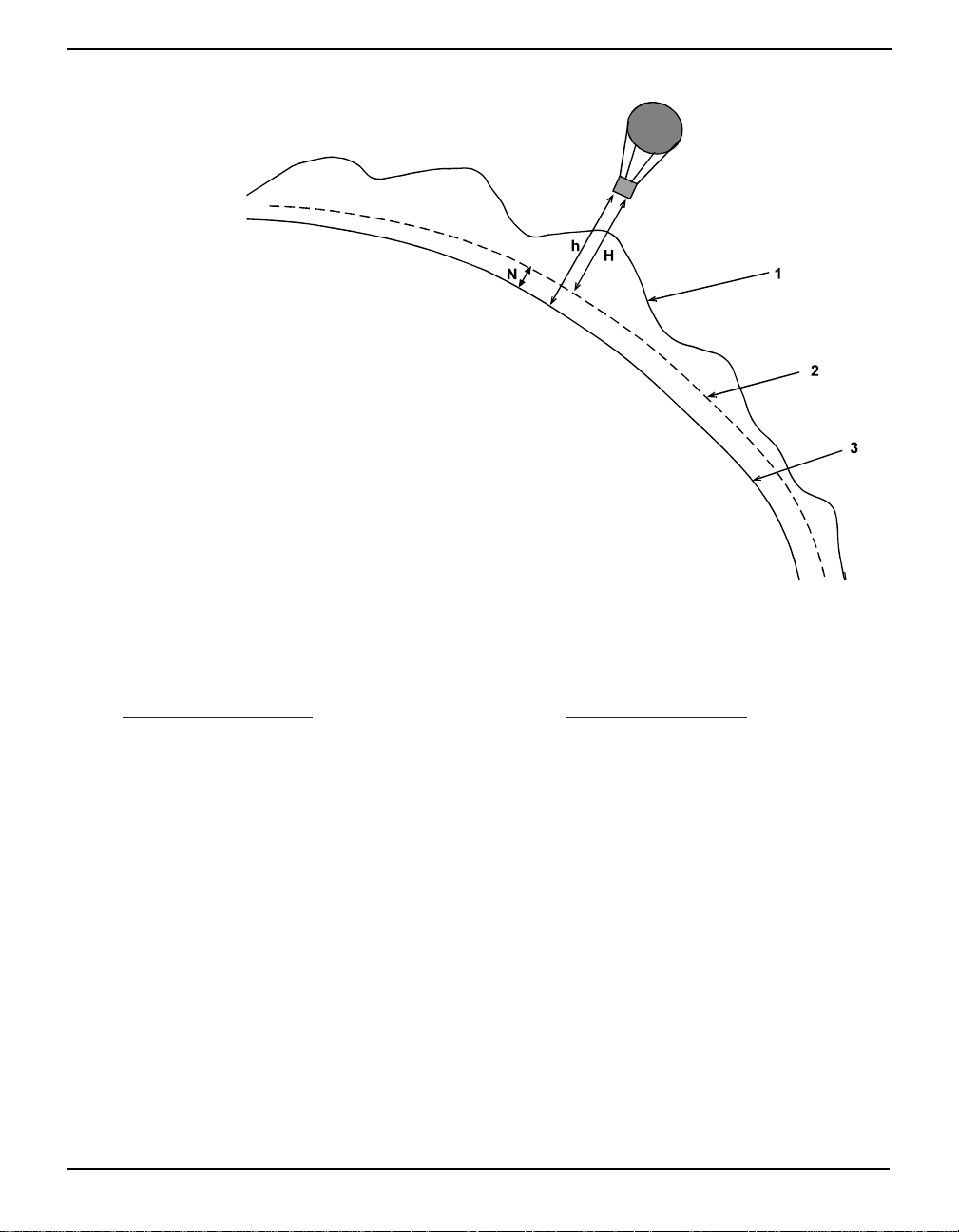
GPS Overview Appendix B
Figure 80: Illustration of GPSCard Height Measurements
References:
1 Topography
2 Geoid (mean sea level)
3 Spheroid (ellipsoid)
H = GPSCard computed height above/below geoid
N = Geoidal Height (undulation )
h = GPS system compute d height above the sphe roid
N = h - H
From the above diagram, and the formula h = H + N, to convert heights between the ellipsoid and
geoid we require the geoid-ellipsoid separation value. This value is not easy to determine. A worldwide model is generally used to provide these values. NovAtel GPS receivers store this valu e
internally. This model can also be augmented with local height and gravity information. A more
precise geoid model is available from gover nment survey agencies e.g . U.S. National Geodetic Survey
(http://www.ngs.noaa.gov
) or Geodetic Survey of Canada (http://www.geod.emr.ca).
Why is this important for GPS users?
The above formula is critical for GPS users as they typically obtain ellipsoid heights and need to
convert these into mean sea-level heights. On ce this conversion is complete, u sers can relate their GPS
derived heights to more “usable” mean sea-level heights.
B.3 GPS Positioning
GPS positioning can be categorized as follows:
1. si ng le- poi n t or rel ative
2. static or kinematic
3. real-time or post-mission data processing
A distinction should be made between accuracy and precision. Accuracy refers to how close an
estimate or measurement is to the true but unknown value; precision refers to ho w c lo se a n es tim a te is
to the mean (average) estimate. “Accuracy versus Pr ecision ” on Page 84 illustrates various
relationships between these two parameters: the true value is "located" at the intersection of the cross-
MPC User Manual Rev 0D 83
Page 84

Appendix B GPS Overview
hairs, the centre of the shaded area is the "location" of the mean estimate, and the radius of the shaded
area is a measure of the uncertainty contained in the estimate.
Figure 81: Accuracy versus Precision
1
High accuracy,
high precision
High accuracy,
low precision
Low accuracy,
high precision
Low accuracy,
low precision
B.3.1 Single-Point vs. Relative Positioning
In single-point positioning, coordinates of a GPS receiver at an unknown location are sought with
respect to the earth’s reference frame by using the known positions of GPS satellites being tracked.
The position solution generated by the receiver is initially developed in earth-centered coordinates
which can subsequently be converted to any other coordinate system. With as few as four GPS
satellites in view, the absolute position of the receiver in three-dimensional space can be determined.
Only one receiver is needed. With Selective Availability (SA) active, the typical horizontal accuracy
obtainable using single-point positioning is of the order of 100 m (95% of the time).
In relative positioning, also known as differential positioning, the coordinates of a GPS receiver at an
unknown point (the “remote” station) are sought with respect to a GPS receiver at a known point (the
“reference” station). The concept is illustrated in Figure 82 on Page 85. The relative-position
accuracy of two receivers locked on the same satellites and not far removed from each other - up to
tens of kilometers - is extremely high. The largest error contributors in single-point positioning are
those associated with SA and atmospheric-induced effects. These errors, however, are highly
correlated for adjacent receivers and hence cancel out in relative measurements. Since the position of
the reference station can be determined to a high degree of accuracy using conventional surveying
techniques, any differences between its known position and the position computed using GPS
techniques can be attributed to various components of error as well as the receiver’s clock bias. Once
the estimated clock bias is removed, the remaining error on each pseudorange can be determined. The
reference station sends information about each satellite to the remote station, which in turn can
determine its position much more exactly than would be possible otherwise.
The advantage of relative positioning is that much greater precision (presently as low as 2 mm,
depending on the method and envi ronmen t) can b e achieve d than by sing le-poin t pos itioni ng. In order
for the observations of the reference station to be integrated with those of the remote station, relative
1.Environment Canada, 1993, Guideline for the Application of GPS Positioning, p. 22.
Minister of Supply and Services Canada
84 MPC User Manual Rev 0D
Page 85
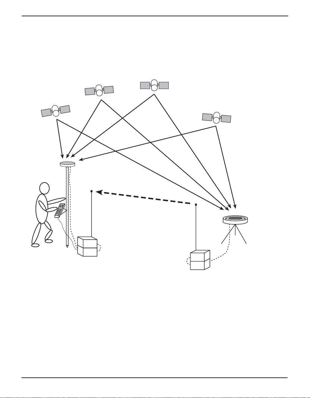
GPS Overview Appendix B
)
positioning requires either a data link between the two stations (if the positioning is to be achieved in
real-time) or else post-processing of the data collected by the remote station. At least four GPS
satellites in view are still required. The absolute accuracy of the remote station’s computed position
will depend on the accuracy of the reference station’s position.
Figure 82: Example of Differential Positioning
GPS satellites
GPS antenna
User with hand-held
computer
Radio
RX
GPS
RX
Remote station
Differential
data
Radio
TX
GPS
RX
Reference station
GPS antenna
(shown with
choke-ring ground plane
B.3.2 Static vs. Kinematic Positioning
Static and kinematic positioning refer to whether a GPS receiver is stationary or in motion while
collecting GPS data.
B.3.3 R e al- t ime vs . Post- mis sion Data Processing
Real-time or post-mission data processing refer to whether the GPS data collected by the receiver is
processed as it is received or after the entire data-collection session is complete.
MPC User Manual Rev 0D 85
Page 86

Appendix B GPS Overview
B.4 Differential Positioning
There are two types of differential positioning algorithms: pseudorange and carrier phase. In both of
these approaches, the “quality” of the positioning solution generally increases with the numb er of
satellites which can be simultaneously viewed by both the reference and remote station receivers. As
well, the quality of the positioning solution increases if the distribution of satellites in the sky is
favorable; this distribution is quantified by a figure of merit, the Position Dil ution of Precision
(PDOP), which is defined in such a way that the lower the PDOP, the better the solu tion.
Due to the many different applications for differential positioning systems, two types of position
solutions are possible. NovAtel’s carrier-phase algorithms can generate both matched and low-latency
position solutions, while NovAtel’s pseudorange algorithms generate only low-latency solutions.
These are described below:
1. The matched positio n solution is comp uted at the remote station w hen the observatio n information for a given epoch has arrived from the refer ence station via the data l ink. Matched
observation set pairs are observations by both the r eference and remo te statio ns which are
matched by time epoch, and contain the same satellites. The matched posit ion solution is
the most accurate one available to the operator of the remote station, but it has an inherent
latency – the sum of time delays between the moment that the reference station makes an
observation and the moment that the differential information is processed at the remote station. This latency depends on the computing speed of the reference station receiver, the
rates at which data is transmitted through the various links, and the computing speed of the
remote station; the overall delay is on the ord er of one second. Furthermore, th is position
cannot be computed any more often than the observations are sent from the reference station. Typically, the update rate is one solution every two seconds.
2. The low latency position solution is based on a prediction from the reference station. Instead
of waiting for the observations to arrive from the reference station, a model (based on previous reference station observations) is u sed to est imate wh at the o bservation s will be at a
given time epoch. These estimated reference station observations are com bined with actual
measurements taken at the remote station to provide the position solution. Because only the
reference station observations are predicted, the remote station’s dyn amics will be accurately reflected. The latency in this case (the time delay between the moment that a measurement is made by the remo te station and the moment th at a position is made availab le) is
determined only by the remote processor’s com putational capacity ; the overall delay is of
the order of a hundred milliseconds. Low-latency position solutions can be computed more
often than matched position solutions; the update rate can reach 10 solutions per second.
The low-latency positions will be provided for data gaps between matched positions of up
to 30 seconds (for a carrier-phase solution) or 60 seconds (for a pseudorange solution, unless adjusted using the DGPSTIMEOUT command) . A general guid eline for the additi onal
error incurred due to the extrapolati on pro cess is show n in Table 4.
Table 4: Latency-Induced Extrapolation Error
Time since last reference
station observation
0-2 seconds 1 cm/sec
2-7 seconds 2 cm/sec
7-30 seconds 5 cm/sec
Typical extrapolation
error (CEP) rate
86 MPC User Manual Rev 0D
Page 87

GPS Overview Appendix B
B.5 Pseudorange Algorithms
Pseudorange algorithms correlate the pseudorandom code on the GPS signal received from a
particular satellite, with a version generated within the reference station receiver itself. The time delay
between the two versions, multiplied by the speed of light, yields the pseudorange (so called because
it contains several errors) between the reference station and that particular satellite. The availability of
four pseudoranges allows the reference station receiver to compute its position (in three dimensions)
and the offset required to synchronize its clock with GPS system time. The discrepancy between the
reference station receiver’s computed position and its known position is due to errors and biases on
each pseudorange. The reference station receiver sums these errors and biases for each pseudorange,
and then broadcasts these corrections to the remote station. The remote receiver applies the
corrections to its own measurements; its corrected pseudoranges are then processed in a least-squares
algorithm to obtain a position solution.
The “wide correlator” receiver design that predominates in the GPS industry yields accuracies of 3-5
m (SEP). NovAtel’s patented Narrow Correlator tracking technology reduces noise and multipath
interference errors, yielding accuracies of 1 m (SEP).
B.5.1 Pseudorange Differential Positioning
B.5.1.1 GPS System Errors
In general, GPS SPS C/A code single-point pseudorange positioning systems are capable of absolute
position accuracies of about 40 meters or less. This level of accuracy is really only an estimation, and
may vary widely depending on n umerous GPS sy stem biases, env ironmental conditions, as well as the
GPS receiver design and engineering quality.
There are numerous factors which influence the single-p oint position accuracies of any GPS C/A code
receiving system. As the following list will show, a receiver’s performance can vary widely when
under the influences of these combined system and environmental biases.
• Ionospheric Group Delays – The earth’s ionospheric layers cause varying degrees of GPS
signal propagation delay. Ionization levels tend to be highest during daylight hours causing
propagation delay errors of up to 30 meters, whereas night time levels are much lower and
may be as low as 6 meters.
• Tropospheric R efraction Delays – The earth’s tropospheric layer causes GPS signal
propagation delays. The amount of delay is at the minimum (about three metres) for satellite
signals arriving from 90 degrees above the horizon (overhead), and progressively increases
as the angle above the horizon is reduced to zero where delay errors may be as much as 50
metres at the horizon.
• Ephemeris Errors – Some degree of error always exists between the broadcast ephemeris’
predicted satellite position and the actual orbit position of the satellites. These errors will
directly affect the accuracy of the range measurement.
• Satellite Clock Errors – Some degree of error also exists between the actual satellite clock
time and the clock time predicted by the broadcast data. This broadcast time error will cause
some bias to the pseudorange measurements.
• Receiver Clock Errors – Receiver clock error is the time difference between GPS receiver
time and true GPS time. All GPS receivers have differing clock offsets from GPS time that
vary from receiver to receiver by an unknown amount depending on the oscillator type and
quality (TCXO vs. OCXO, etc.). However, because a receiver makes all of its single-point
pseudorange measurements using the same common clock oscillator, all measurements will
be equally offset, and this offset can generally be modeled or quite accurately estimated to
MPC User Manual Rev 0D 87
Page 88

Appendix B GPS Overview
effectively cancel the receiver clock offset bias. Thus, in single-point positioning, receiver
clock offset is not a significant problem. However, in pseudorange differential operation,
between-receiver clock offset is a source of uncorrelated bias.
• Selective Availability (SA) – Selective availability is when the GPS Control Segment
intentionally corrupts satellite clock timing and broadcast orbit data to caus e reduced
positioning accuracy for general purpose GPS SPS users (non-military). When SA is active,
range measurements may be biased by as much as 30 metres.
NovAtel’s OEM4 GPSCard is a civilian dual frequency GPS receiver that normally tracks:
• L1 C/A Code
•L1 Carrier Phase
• L2 P or Y Code
• L2 (Codel ess) Carrier Phase
P Code is never tracked on L1 even if AS is disabled.
• Multipath Signal Reception – Multipath signal reception can potentially cause large
pseudorange and carrier phase measurement biases. Multipath conditions are very much a
function of specific antenna site location versus local geography and man-made structural
influences. Severe multipath conditions could skew range measurements by as much as 100
meters or more.
The NovAtel GPSCard receivers are capable of absolute single-point positioning accuracies of 15
meters CEP (GDOP < 2; no multipath) when SA is off and 40 meters CEP while SA is on. (As the
status of selective availability is generally unknown by the real-time GPS user, the positioning
accuracy should be considered to be that of when SA is on).
The general level of accuracy available from single-po int opera tion may be suitable for many types of
positioning such as ocean going vessels, general aviation, and recreational vessels that do not require
position accuracies of better than 40 meters CEP. However, increas ingly more and more applications
desire and require a much higher degree of accuracy and position confidence than is possible with
single-point pseudoran ge positioning. This is where diff erential GPS (DGPS) plays a dominan t role in
higher accuracy real-time positioning systems.
88 MPC User Manual Rev 0D
Page 89

GPS Overview Appendix B
B.5.1.2 Single-Point Averaging with the GPSCard
By averaging many GPS measurement epochs over several hours, it is possible to achieve a more
accurate absolute position. This section attempts to explain how the position averaging function
operates and to provide an indication of the level of accuracy that can be expected versus total
averaging time.
The POSAVE command implements position averaging for reference stations. Position averaging will
continue for a specified number of hours or until the averaged position is within specified accuracy
limits. Averaging will stop when the time limit or
the horizontal standard deviation limit or the
vertical standard deviation limit is achieved. When averaging is complete, the FIX POSITION
command will automatically be invoked.
If the maximum time is set to 1 hour or larger, positions will be averaged every 10 minutes and the
standard deviations reported in the AVEPOS log should be correct. If the maximum time is set to less
than 1 hour, positions will be averaged once per minute and the standard deviations reported in the log
will likely not be accurate; also, the optional horizontal and vertical standard deviation limits cannot
be used.
If the maximum time that positions are to be measured is set to 24, for example, you can then log
AVEPOS with the trigger ‘ontime’ to see the averaging status. i.e.,
posave 24
log com1 avepos onchanged
You could initiate differential logging, then issue the POSAVE command followed by the
SAVECONFIG command. This will cause the GPSCard to average positions after every power-on or
reset, then invoke the FIX POSITION command to enable it to send differential corrections.
The position accuracy that may be achieved by these methods will be dependent on many factor s: SA,
average satellite geometry, sky visibility at antenna location, satellite health, time of day, etc. The
following graph summarizes the results of sever a l examples of position averaging over different time
periods. The intent is to provide an idea of the relationship between averaging time and position
accuracy. All experiments were performed using a single frequency receiver with an ideal antenna
location, see Figure 83.
MPC User Manual Rev 0D 89
Page 90
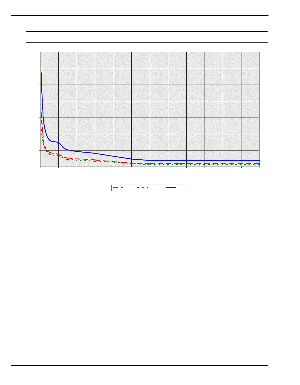
Appendix B GPS Overview
Figure 83: Single-Point Averaging
* This graph represents typical results using position averaging.
35
30
25
20
15
Standard Deviation (meters)
10
5
0
0 4 8 12162024283236404448
Time (hours)
Latitude Longtitude Height
This function is useful for obtaining the WGS84 position of a point to a reasonable accuracy without
having to implement differential GPS. It is interesting to note that even a six hour occupation can
improve single-point GPS accuracy from over fifty meters to better than five meters. This improved
accuracy is primarily due to the reductions of the multipath and selective availability errors in the GPS
signal.
Again, it is necessary to keep in mind that the resulting standard deviations of the position averaging
can vary quite a bit, especially over relatively short averaging times. To illustrate, the position
averaging function was run for a period of one hour at three different times during the day. The
resulting standard deviation in latitude varied from 4.7 to 7.0 meters. Similarly, the variation in
longitude and height were 4.9 to 6.7 meters and 10.9 to 12.5 meters respectively. This degree of
variation is common for averaging periods of less than 12 hours due to changes in the satellite
constellation. The graph, however, should at least provide some indication of the accuracy one may
expect from single-point position averaging.
90 MPC User Manual Rev 0D
Page 91
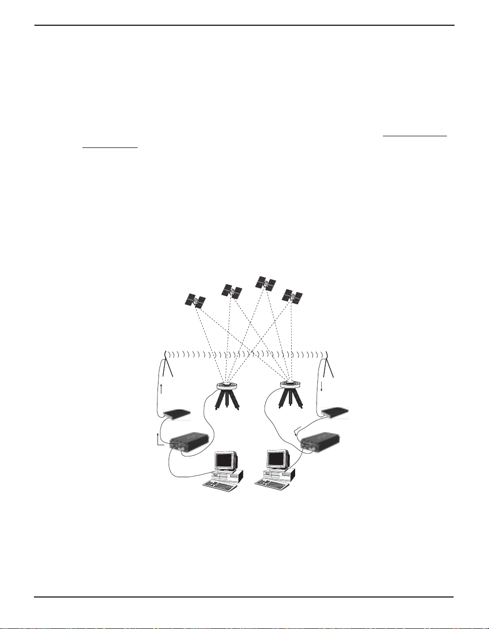
GPS Overview Appendix B
B.5.2 Dual Station Differential Positioning
It is the objective of operating in differential mode to either eliminate or greatly reduce most of the
errors introduced by the above types of system biases. Pseudorange differential positioning is quite
effective in removing most of the biases caused by satellite clock error, ionospheric and tropospheric
delays (for baselines less than 50 km), ephemeris prediction errors, and SA. However, the biases
caused by multipath reception and receiver clock offset are uncorrelated between receivers and thus
cannot be cancelled by "between receiver single differencing" operation.
Differential operation requires that stations operate in pairs. Each pair consists of a reference station
and a remote station
. A differential network could also be established when there is more than one
remote station linked to a single reference station.
In order for the differential pair to be effective, differential positioning requ ires that both reference
and remote station receivers track and collect satellite data simultaneously from common satellites.
When the two stations are in relatively close proximity (< 50 km), the pseudorange bias errors are
considered to be nearly the same and can be effectively cancelled by the differential corrections.
However, if the baselin e beco mes exces sively long , the bias erro rs beg in to d ecorr elate, thus r e ducing
the accuracy or effectiveness of the differential corrections.
Figure 84: Typical Differential Configuration
Radio Data Link
GPSAntenna
With Chokering
Differential
Corrections
Input
Modem
Differential
Corrections
Output
Reference Station
GPS Receiver
Remote Station
MPC User Manual Rev 0D 91
Page 92

Appendix B GPS Overview
B.5.2.1 The Reference Station
The nucleus of the differential network is the reference station. To function as a reference station, the
GPS receiver antenna must be positioned at a control point whose position is precisely known in the
GPS reference frame. Typically, the fixed position will be that of a geodetic marker or a pre-surveyed
point of known accuracy.
The reference receiver must then be initialized to fix its position to agree with the latitude, longitude,
and height of the phase centre of the reference station GPS receiver antenna. Of course, the antenna
offset position from the marker must be accurately accounted for.
Because the reference station’s position is fixed at a known location, it can now compute the range of
its known position to the satellite. The reference station now has two range measurements with which
to work: computed pseudoranges based on its known position relative to the satellite, and measured
pseudoranges which assumes the receiver position is unknown. Now, the reference station’ s measured
pseudorange (unknown posit ion) is differen ced against the computed range (based on kn own position)
to derive the differential correction which represents the difference between known and unknown
solutions for the same antenna. This difference between the two ranges represents the combined
pseudorange measurement errors resulting from receiver clock errors, atmospheric delays, satellite
clock error, orbital errors, and SA.
The reference station will derive pseudorange corrections for each satellite being tracked. These
corrections can now be transmitted over a data link to one or more remote stations. It is important to
ensure that the reference station’s FIX POSITION setting be as accurate as possible, as any errors here
will directly bias the pseudorange corrections computed, and can cause unpredictable results
depending on the application and the size of the reference station position errors. As well, the
reference station’s pseudorange measurements may be biased by multipath reception.
B.5.2.2 The Remote Station
A remote station is generally any receiver whose position is of unknown accuracy, but has ties to a
reference station through an established data link. If the remote station is not receiving differential
corrections from the reference station, it is essentially utilizing single-point positioning measurements
for its position solutions, thus is subject to the various GPS system biases. However, when the remote
GPS receiver is receiving a pseudorange correction from the reference station, this correction is
applied to the local receiver’s measured pseudorange, effectively cancelling the effects of orbital and
atmospheric errors (assuming baselines < 50 km), as well as eliminating satellite clock error.
The remote station must be tracking the same satellites as the reference station in order for the
corrections to take effect. Thus, only common satellite pseudoranges will utilize the differential
corrections. When the remote is able to compute its positions based on pseudorange corrections from
the reference station, its position accuracies will approach that of the reference station. Remember, the
computed position solutions are always that of the GPS receiving antenna phase centre.
92 MPC User Manual Rev 0D
Page 93

GPS Overview Appendix B
B.6 Carrier-Phase Algorithms
Carrier-phase algorithms monitor the actual carrier wave itself. These algorithms are the ones used in
real-time kinematic (RTK) positioning solutions - differential systems in which the remote station,
possibly in motion, requires reference-station observation data in real-time. Compared to pseudorange
algorithms, much more accurate position solutions can be achieved: carrier-based algorithms can
achieve accuracies of 1-2 cm (CEP).
Kinematic GPS using carrier-phase observations is usually applied to areas where the relation
between physical elements and data collected in a moving vehicle is desired. For example, carrierphase kinematic GPS missions have been performed in aircraft to provide coordinates for aerial
photography, and in road vehicles to tag and have coordinates for highway features. This method can
achieve similar accuracy to that of static carrier-phase, if the ambiguities can be fixed. However,
satellite tracking is much more difficult, and loss of lock makes reliable ambiguity solutions difficult
to maintain.
A carrier-phase measurement is also referred to as an accumulated delta range (ADR). At the L1
frequency, the wavelength is 19 cm; at L2, it is 24 cm. The instantaneous distance between a GPS
satellite and a receiver can be thought of in terms of a number of wavelengths through which the
signal has propagated. In general, this number has a fractional component and an integer component
(such as 124 567 967.330 cycles), and can be viewed as a pseudorange measurement (in cycles) with
an initially unknown constant integer offset. Tracking loops can compute the fractional component
and the change in the integer component with relative ease; however, the determination of the initial
integer portion is less straight-forward and, in fact, is termed the ambiguity.
In contrast to pseudorange algorithms where only corrections are broadcast by the reference station,
carrier-phase algorithms typically “double difference” the actual observations of the reference and
remote station receivers. Double-differenced observations are those formed by subtracting
measurements between identical satellite pairs on two receivers:
ADR
double difference
= (ADR
rx A,sat i
- ADR
rx A,sat j
) - (ADR
rx B,sat i
- ADR
rx B,sat j
)
An ambiguity value is estimated for each double-difference observation. One satellite is common to
every satellite pair; it is called the reference satellite, and it is generally the one with the highest
elevation. In this way, if there are n satellites in view by both receivers, then there will be n-1 satellite
pairs. The difference between receivers A and B removes the correlated noise effects, and the
difference between the different satellites removes each receiver’s clock bias from the solution.
In the RTK system, a floating (or “continuous-valued”) ambiguity solution is continuously generated
from a Kalman filter. When possible, fixed-integer ambiguity solutions are also computed because
they are more accurate, and produce more rob ust stan dard -dev iation es timates. Each po ssible dis crete
ambiguity value for an observation defines one lane; that is, each lane corresponds to a possible
pseudorange value. There are a large number of possible lane combinations, and a receiver has to
analyze each possibility in order to select the correct one. For single-frequency receivers, there is no
alternative to this brute-force approach. However, one advantage of being able to make both L1 and
L2 measurements is that linear combinations of the measurements made at both frequencies lead to
additional values with either “wider” or “narrower” lanes. Fewer and wider lanes make it easier for
the software to choose the correct lane, having used the floating solution for initialization. Once the
correct wide lane has been selected, the software searches for the correct narrow lane. Thus, the
MPC User Manual Rev 0D 93
Page 94

Appendix B GPS Overview
searching process can more rapidly and accurately home in on the correct lane when dual-frequency
measurements are available. Changes in the geometry of the satellites aids in ambiguity resolution;
this is especially noticeable in L1-only solutions. In summary, NovAtel’s RTK system permits L1/L2
receivers to choose integer lanes while forcing L1-only receivers to rely exclusively on the floating
ambiguity solution.
Once the ambiguities are known, it is possible to solve for the vector from the reference station to the
remote station. This baseline vector, when added to the position of the reference station, yields the
position of the remote station.
In the NovAtel RTK system, the floating ambiguity and the integer position solutions (when both are
available) are continuously compared for integrity purposes. The better one is chosen and output in
the receiver’s matched-position logs. The “best” ambiguities determined are used with the remote
station’s local observations and a reference station observation model to generate the remote station’s
low-latency observations.
94 MPC User Manual Rev 0D
Page 95

Appendix C WAAS Overview
The Wide Area Augmentation System (WAAS) is a safety-critical system that provides a quality of
positioning information previously unavailable. The WAAS improves the accuracy, integrity, and
availability of the basic GPS signals. In the future, the wide area of coverage for this system will
include the entire United States and some outlying areas. At the time of publication, there are two
WAAS satellites over the western Atlanti c Ocean and the Pacific (PRN 122 and PRN 134
respectively) and one EGNOS satellite over the eastern Atlantic Ocean (PRN 120). WAAS data is
available from any of these satellites and more satellites will be available in the future.
The primary functions of WAAS include:
•data collection
•determining ionospheric corrections
•determining satellite orbits
•determining satellite clock corrections
•determining satellite integrity
•independent data verification
•WAAS message broadcast and ranging
•system operations & maintenance
As shown in Figu re on Page 96, the WAAS is made up of a series of Wide Area Reference Stations,
Wide Area Master Stations, Ground Uplink Stations and Geostationary Satellites (GEOs). The Wide
Area Reference Stations, which are geographically distributed, pick up GPS satellite data and route it
to the Wide Area Master Stations where wide area corrections are generated. These corrections are
sent to the Ground Uplink Stations which up-link them to the GEOs for re-transmission on the GPS
L1 frequency. These GEOs transmit signals which carry accuracy and integrity messages, and which
also provide additional ranging signals for added availability, continuity and accuracy. These GEO
signals are available over a wide area and can be received and processed by OEM4 family GPS
receivers with appropriate firmware. GPS user receivers are thus able to receive WAAS data in-band
and use not only differ ential corrections, b ut also integrity, residual errors and ionospheric information
for each monitored satellite.
The signal broadcast via the WAAS GEOs to the WAAS users is designed to minimize modifications
to standard GPS receivers. As such, the GPS L1 frequency (1575.42 MHz) is used, together with
GPS-type modulation - e.g. a Coarse/Acquisition (C/A) pseudorandom (PRN) code. In addition, the
code phase timing is maintained close to GPS time to provide a ranging capability.
MPC User Manual Rev 0D 95
Page 96
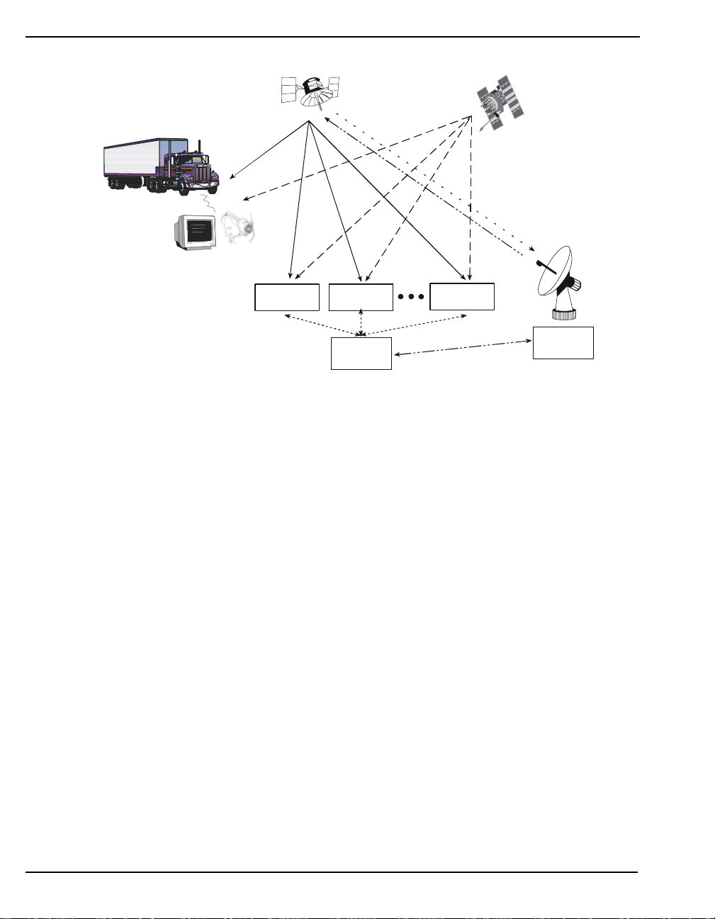
Appendix C WAAS Overview
Ground UplinkStation(GUS)
Integrity data,differential corrections
,
time control, and statu
s
G
ta,
corrections
,
contro
l
eostationary
Satellite (GEO)
L1
GPS User
Wide-area
Reference Station
(WRS)
Figure 85: The WAAS Concept
C.1 MPC with the WAAS Option
L1 & C-band
Wide-area
Reference Station
(WRS)
Wide-area
Master Station
(WMS)
GPS Satellite
Constellation
L1 & L2
Wide-area
Reference Station
(WRS)
C-band
Integrity da
differential
and ranging
The L1L2W model of the MPC is equipped with the WAAS/EGNOS option. The ability to
simultaneously track two WAAS satelli tes, and incorporate the WAAS/EGNOS corrections in to the
position, is available in this model.
This model can output the WAAS data in log format (RAWWAASFRAMEA/B, WAAS0A/BWAAS27A/B), and can incorporate these corrections to generate differential-quality position
solutions. Standard WAAS/EGNOS data mess ages are analyzed based o n RTCA stand ard DO-229B
Change 1 Minimum Operational Performance Standards for GPS/WAAS airborne equipment.
A WAAS/EGNOS-capable MPC will permit anyone within the area of coverage to take advantage of
its benefits.
C.1.1 WAAS Commands and Logs
The command WAASCORRECTION, enables the use of the WAAS corrections in the position filter.
In order to use this command, first ensure that your receiver is capable of receiving WAAS
corrections.
Several WAAS specific logs also exist and are all prefixed by the word WAAS except for the
RAWWAASFRAME log.
The PSRDIFFSOURCE command sets the station ID value which identifies the reference station from
which to accept psuedorange corrections. All DGPS types may revert to WAAS, if enabled using the
WAASCORRECTION command.
Consult Volume 2 of the OEM4 Users’ Guide for more details on individual WAAS commands and
logs.
96 MPC User Manual Rev 0D
Page 97

Appendix D Replacement Parts
The following are a list of the replacement parts available fo r your NovAtel GPS receiver. Should you
require assistance or need to order additional componen ts, please contact your local NovAtel dealer or
Customer Service representative.
Table 5: MPC Power Cable
Part Description NovAtel Part
MPC power cable assembly 01017085
Table 6: Accessories and Options
Part Description NovAtel Part
Modulated Pr ecision Clock (MPC) MPC
Euro4 GPSCard Euro4
PC Software CD 01016826
Optional OEM4 GPSCard Command Description Manual Volume 1, Installation
and Operation
OEM4 GPSCard Command Description Manual Volume 2, Commands and Logs OM-20000047
Optional NovAtel GPSAntennas: Model 600 (L1/L2) GPS-600
Model 501 (L1 only) GPS-501
Model 511 (L1 only) GPS-511
Model 521 (L1 only) GPS-521
Model 502 (L1/L2) GPS-502
Model 503 (L1/L2) GPS-503
Model 512 (L1/L2) GPS-512
Optional RF Antenna Cable: 5 meters (16.4’) C005
15 meters (49.2’) C015
30 meters (98.4’) C030
22 cm (8.66”) interconnect adapter cable GPS-C002
OM-20000046
MPC User Manual Rev 0D 97
Page 98

Index
10 MHz in/out, 20, 24
1PPS, 24
A
accessories, 15, 97
accuracy, 76
horizontal, 84
positioning, 87–93
reference station, 92
aerial photograph, 93
almanac data, 82
ambiguity, fixed, 93
analysis plots, 67–69, 71
antenna
active
, 18, 23
cables, 18, 23, 97
dual-frequency, 18
input, 77
models, 18, 97
power, 18
single-frequency, 18
site, 88
atmosphere, 84, 92
authorization code, 14
B
base configuration, 55, 63
base station, 39
BNC connector, 20, 24
broadcast
corrections
ephemeris, 87
overview, 82
, 87, 93
C
C/A code, 82
cables, 16, 19, 23, 97
antenna, 18
coaxial, 18, 23
extended cable lengths, 18
patch RJ11, 21
patch RJ45, 21
power, 80
warranty, 9
calendar, 72
carrier-phase, 86
carrying handle, 14
cautions, 11, 19
client
configure
connect, 26–36
clock
bias
data, 82
external, 20
offset, 88
synchronization, 87
CMR, 63
coaxial cable, 18, 23, 97
COM ports, 79
commands
enter
OEM4 Users’ Guide, 97
position averaging, 89
pre-configuring, 39
summary, 52–54
communications cable, 20
configuration, 14, 17
base, 55, 63
differential, 91
factory, 18
internet, 17, 46–48, 55, 59
connectors, 16, 19–20, 25, 77
constellation, 70, 81
conversion, 83
copyright, 2
current (amp), 11
customer service, 10
, 36, 45, 47–48
, 84, 93
, 55
D
data
link
, 85
rates, 76
MPC User Manual Rev 0D 98
Page 99

Index
DC, 23, 77
dealer, 10
DGPS, 20, 38
differential
corrections
operation, 14
positioning, 84, 86–87, 91
dilution of precision (DOP), 86, 88
distance, 93
download data, 72–74
, 89, 91–92
E
elevation, 93
e-mail, 10
ENTER key, 23, 41, 43–44
ephemeris
errors
, 87, 91
overview, 82
errors, 39
ephemeris, 87
in single-point positioning, 84
ESC key, 23, 41, 43–44
Ethernet, 21, 25–26
extended cable lengths, 18
external clock, 20
F
factory, 18
features, 14
filename, 51
firmware, 10, 14, 75
fix position, 63
fixed ambiguities, 93
frequency, 93
front end-cap, 23
fuse, 22
G
GEO, WAAS, 95
GPS
antenna
Antenna In, 23
calendar, 72–73
overview, 81–88, 90–94
time, 87
, 9, 97
H
handle, 14
height, 82–83, 92
host, 48
humidity, 77
I
I/O, 19, 77, 79
impedance, 77
indicators, 23
input, 77
integration, 12–13
internet connection, 55
introduction, 13
ionospheric, 87, 91
IP address, 17
K
keypad, 14, 23, 40–41
kinematic positioning, 85, 93
L
latency, 86
latitude, 81, 92
L-band frequency, 82
LED, 23
license, 8
logging, 38, 50, 52, 55
longitude, 81, 92
loop-back connector, 20
loss of lock, 93
low-noise amplifier (LNA), 23, 77
M
Mark In, 24
master control station, 82
mean sea level, 81
menu, VFD, 41
models, 14
Modem, 21, 26
multipath, 18, 87
N
Narrow Correlator tracking technology, 87
MPC User Manual Rev 0D 99
Page 100

Index
navigation, 81
NAVSTAR satellites, 81
network
configuration
I/O, 21
noise, 87, 93
notices, 11
NovAtel Inc., 2, 8–10, 97
, 25–38
O
OCXO, see oscillators
OEM4 Users’ Guide
offset, 87, 92–93
on/off (-/o) switch, 16
options, 15, 97
orbit period, 81
oscillators, 87
output, 77
, 97
P
parse responses, 53–54
part numbers, 97
performance, 76
pin-outs, 79
plots, 67–69, 71
ports, 19, 77
communication, 20, 79
RF, 23
position
accuracy
modes of operation, 14
static, 93
post-processed, 14
power, 77
cable, 23, 80
connector, 22
interruptions, 22, 39
port, 23
supply, 22
PPP, 21, 26
precision, 76, 82–84, 86
processing, 82–83, 85
program software, 14
propagation, 87
pseudorange, 84, 86–87, 92–93
, 76
Q
quick start, 16–17
R
radio frequency (RF), 18, 23
reacquisition, 76
real-time, 83, 85, 88, 93
rear panel, 19
receiver parameters, 56
reference station, 39, 89, 91–92, 94
reload firmware, 55, 65
remote station, 39, 85, 87, 91, 94
replacement parts, 97
response sum mary, 52–54
revision, firmware, 1, 10
RF Loop-Back, 20
RF, see radio frequency
rover station
row cursor, 40
RS232, 20, 79
RTCM, 63
RTK, 14, 93
, 39
S
SA, see selective availability
satellite
schedule, 52
segment
selective availability (SA), 84, 88
self-test, 25
serial ports, 21
setting up, 16, 21, 38
single point, 14
size, 77
software upgrades and updates, 75
space vehicle number (SVN), 82
specifications, 77–78
speed, 87
statistics, 55
supply voltage, 22
support, 9–10
surveying, 83–84, 92
SVN, see space vehicle number
, 18, 81
control
, 81–82, 88
space, 81
user, 81–82
100 MPC User Manual Rev 0D
 Loading...