

MPC netframe NF1610, netframe NF2610, netframe NF3610, netframe NF6600, netframe NF600 Quick Start Manual
...
NetFRAME
®
Quick Start Guide
NF1610
NF2610
NF3610
NF6600


i
. . . . . . . . . . . . . . .
Table of Contents
Copyright Notice................ ................................................................. .. iii
Trademark Notice........................................................................................ iii
Limitation of Liability.................................................................................... iii
Life Support — Nuclear Facilities................................................................ iii
Welcome........... ....... ...... ...... ....... ...... ....... ...... ....... ........ 1
Technical Reference Manual................................................................ 1
Manual Conventions............................................................................. 2
Special Text ................................................................................................ 2
NF1610 System Features.......... ...... ....... ...... ....... ...... .. 3
NF1610 Front Panel..................................... .. ..... .. .. .. .. .. .. .... ..... .. .. .. .. .. .. 4
NF1610 Front Panel View ........................................................................... 4
NF1610 Back Panel ............................................................................. 5
NF1610 Back Panel View ........................................................................... 5
NF1610 Front Control Panel ................................................................ 6
NF1610 Front Control Panel View .............................................................. 6
NF1610 Control Button Description ............................................................ 7
NF1610 Front Control Panel LED Description ............................................ 8
NF1610 Top Panel...................................................................... .. .... .. .. 9
NF1610 Top Panel View ............................................................................. 9
NF2610 System Features .......................................... 11
NF2610 Front Panel..................................... .. ..... .. .. .. .. .. .. .... ..... .. .. .. .. .. 12
NF2610 Front Panel View ......................................................................... 12
NF2610 Back Panel ........................................................................... 13
NF2610 Back Panel View ......................................................................... 13
NF2610 Front Control Panel .............................................................. 14
NF2610 Front Control Panel View ............................................................ 14
NF2610 Control Button Description .......................................................... 15
NF2610 Front Control Panel LED Description .......................................... 16
NF2610 Top Panel.................................................... .. .. .. .. .. .. ....... .. .. .. . 17
NF2610 Top Panel View ........................................................................... 17
NF1610/2610 System Board Features ...................... 19
NF1610/2610 System Board Components......................................... 20
NF1610/2610 Memory Specifications ................................................ 22
NF1610/2610 Memory Bank Order ........................................................... 23
NF1610/2610 System Board Jumpers ............................................... 24
NF3610 System Features........................................... 29
NF3610 Pedestal/Rack Chassis......................................................... 30
NF3610 Front Panel View ......................................................................... 30
NF3610 Back Panel View.......................................................................... 31
NF3610 Pedestal/Rack Chassis w/Hot-Swap Power Supply ............. 32
NF3610 Front Panel View ......................................................................... 32
NF3610 Back Panel View.......................................................................... 33
NF3610 Front Control Panel View...................................................... 34
NF3610 Pedestal Chassis Front Control Panel View................................ 34
NF3610 Rack Chassis Front Control Panel View...................................... 35
NF3610 Front Control Panel LED Description .......................................... 36
NF3610 System Board Features ............................... 39
NF3610 System Board Components.................................................. 40
NF3610 Memory Specifications ......................................................... 42
NF3610 System Board Jumpers ........................................................ 43
NF6600 System Features........................................... 47
NF6600 Pedestal Chassis...................................................... ....... .. .. . 48
NF6600 Front Panel View ......................................................................... 48
MAS001426-02.book Page i Monday, May 19, 2003 2:45 PM
ii
NF6600 Front Control Panel View............................................................. 49
Back Panel View........................................................................................ 50
NF6600 Rack Optimized Chassis ...................................................... 51
NF6600 Front Panel View.......................................................................... 51
NF6600 Front Control Panel View............................................................. 52
NF6600 Back Panel View.......................................................................... 53
NF6600 Front Control Panel Descriptions.......................................... 54
NF6600 System Board Features............................... 57
NF6600 System Board Components.................................................. 58
NF6600 Memory Specifications ......................................................... 61
Memory Bank Order .................................................................................. 62
NF6600 Processor Specifications...................................................... 63
NF6600 System Board Jumpers ........................................................ 64
MAS001426-02.book Page ii Monday, May 19, 2003 2:45 PM

Copyright Notice
iii
. . . . .
. . . . . . . . . . . . . . . . . . . . . . . . . . . . . . . . . . . . . . . . . . . . . . . . . . . . . . . . . . . . . . . . . . .
COPYRIGHT NOTICE
Copyright 2003 MPC Computers, LLC. All rights reserved. The information in this document is subject to change
without prior notice in order to improve reliability, design , an d fu nc tion and does not represent a commitment on
the part of the manufactur er . In no eve nt w ill the m anufacturer or seller of an MPC product be liable for direct,
indirect, special, incidental, or consequential dam ages arising out of the use or inability to use the product or
documentation, even if advised of the possibility of such damages. Except as stated in the applicable MPC
Computers, LLC limited warranty, MPC and its affiliates, by this manual, make no other express warranties and all
other warranties, including, without limitation: THE IMPLIED WARRANTY OF MERCHANTABILITY AND THE
IMPLIED WARRANTY OF FITNESS FOR A PARTICULAR PURPOSE ARE HEREBY DISCLAIMED.
This document contains pro pr ie tary in fo rmation that is protected by copyright. No part of this docume nt m ay be
photocopied, reproduced, or translated to another la nguage without the prior written consent of:
MPC Computers, LLC
906 E. Karcher Road, Nampa, Idaho 83687
Trademark Notice
Windows, Windows NT, MS-DOS, and Microsoft are registered trademarks of Microsoft Corporation. Pentium and
Xeon are trademarks or reg i st er ed t ra dem arks of Intel Corporation. Oth er product names mentioned herein are
used for identification pu rposes only and may be trademarks and/or register ed t ra demarks of their respectiv e
companies.
Limitation of Liability
While reas onable efforts have been made to ensure the accuracy of th is manual, the manufactur er and seller
assume no liability resulting from errors or omissions in this manual or from the use of the information contained
herein.
Life Support — Nuclear Facilities
Products sold by MPC are not authorized for use as critic al com ponents in medical devic es or systems or in
nuclear facilities witho ut the express written approval of th e C hief Executive Officer of MPC.
MAS001426-02, KDA, 05-3 0- 2003
MAS001426-02.book Page iii Monday, May 19, 2003 2:45 PM

iv
MAS001426-02.book Page iv Monday, May 19, 2003 2:45 PM
1-1
.
. .
. .
. . . . . . . . . . . . . . . . . . . . . . . . . . . . . . . . . . .
W
ELCOME
1
Thank you for buying an MPC NetFRAME server. This Quick Start Guide provides information to
help you quickly get started using your new server. Please refer to the appropriate chapter for your
server.
. . . . . . . . . . . . . . . . . . . . . . . . . . . . . . . . . . . . . . . . . . . . . . . . . . . . . . . . . . . . . . . . . .
TECHNICAL REFERENCE MANUAL
For detailed information about your server’s case, hardware, system boa rd, error codes, BIO S, and
System Setup Utility, please refer to the NetFRAME
®
Technical Reference Manual located on the
MPC Web site at http://support.buympc.com and on the NetFRAME
®
System Drivers CD that
shipped with your system. To locate the manual on the Drivers CD, do the following:
1 Insert the NetFRAME
®
System Drivers CD into the CD-ROM drive. The CD will autorun.
2 When the installation interface appears, press the Manual button located in the lower-left corner.
The manual will automatically be downloaded to your Windows Desktop.
3 From your Windows Desktop, double click on the NetFRAME T echnical Reference Manual icon to
open the system manual.
MAS001426-02.book Page 1 Monday, May 19, 2003 2:45 PM
WEL CO ME
Manual Conventions
1-2
1
. . . . . . . . . . . . . . . . . . . . . . . . . . . . . . . . . . . . . . . . . . . . . . . . . . . . . . . . . . . . . . . . . . .
MANUAL CONVENTIONS
Note
. . . . . . . . . . . . . . . . . . . . . . . . . . . . . . . . . . . . . . . . . . . .
. . . . . . . . . . . . . . . . . . . . . . . . . . . . . . . . . . . . . . . . . . . .
Important information concerning the operation of your computer.
Caution
. . . . . . . . . . . . . . . . . . . . . . . . . . . . . . . . . . . . . . . . . . . .
Failure to follow directions could result in loss of data or damage to equipment. Failure to heed
. . . . . . . . . . . . . . . . . . . . . . . . . . . . . . . . . . . . . . . . . . . .
these cautions could negate the user warranty.
Special Text
The text in this guide is formatted to highlight unique information or instructions. Review the following
examples of special text used throughout this manual:
• Screen (window) names, functions, or anything that appears on the screen is formatted in bold. For
example: Click OK, the Standards screen, the Edit menu.
• Keyboard strokes are indicated by brackets. For example: Press [Enter], use the [Alt] key. When keys
should be held down simultaneously, they are separated by the + sign. For example: Press
[Ctrl+Alt+Delete]. When keys should be pressed sequentially, they will be in individual brackets
without the plus sign. For example: Press [1][Enter]. The [1] key should be pressed first and then the
[Enter] key should be pressed.
• Screen messages are indicated by quotes. For example: The message “Enter your username and
password” will appear.
• Anything that you need to type will appear in italics. For example: Enter the word password.
MAS001426-02.book Page 2 Monday, May 19, 2003 2:45 PM

2-3
.
. .
. .
. . . . . . . . . . . . . . . . . . . . . . . . . . . . . . . . . . .
NF1610 S
YSTEM
F
EATURES
2
The following chapter provides information about the components and connectors on your
server.
Note
. . . . . . . . . . . . . . . . . . . . . . . . . . . . . . . . . . . . . . . . . . .
. . . . . . . . . . . . . . . . . . . . . . . . . . . . . . . . . . . . . . . . . . .
The appearance, location, and existence of the components mentioned may vary by model.
MAS001426-02.book Page 3 Monday, May 19, 2003 2:45 PM
NF1610 SYSTEM FEATURES
NF1610 Front Panel
2-4
2
. . . . . . . . . . . . . . . . . . . . . . . . . . . . . . . . . . . . . . . . . . . . . . . . . . . . . . . . . . . . . . . . . . .
NF1610 FRONT PANEL
NF1610 Front Panel View
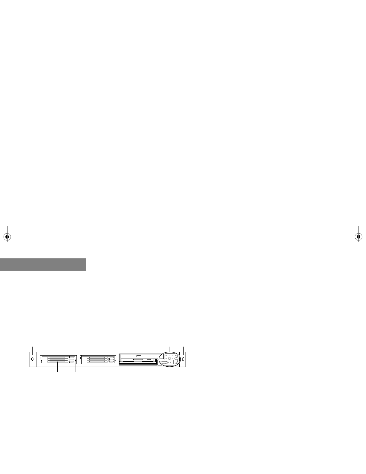
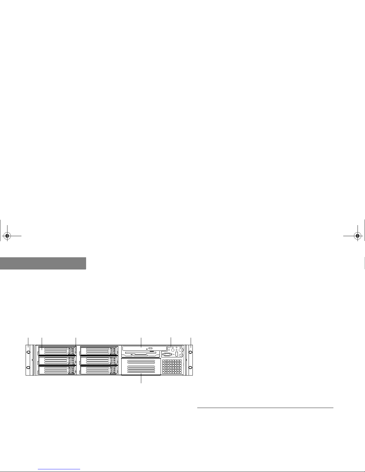
Table 1 and Figure 1 identify the features on the front of your server.
Figure 1. NF1610 Front Panel Component Layout
A D E
BC
F
Table 1: NF1610 Front Panel Components
A
Chassis handle
B
Drive bay (1-inch)
C
HDD activity/fault indicator
D
Flex bay (optional DVD/CD-ROM drive/FDD
module shown)
E
Front Control Panel (for more information refer
to “NF1610 Front Control Panel” on page 2-6)
F
Chassis handle
MAS001426-02.book Page 4 Monday, May 19, 2003 2:45 PM
NF1610 SYSTEM FEATU RES
NF1610 Back Panel
2-5
. . . . .
. . . . . . . . . . . . . . . . . . . . . . . . . . . . . . . . . . . . . . . . . . . . . . . . . . . . . . . . . . . . . . . . . . .
NF1610 BACK PANEL
NF1610 Back Panel View
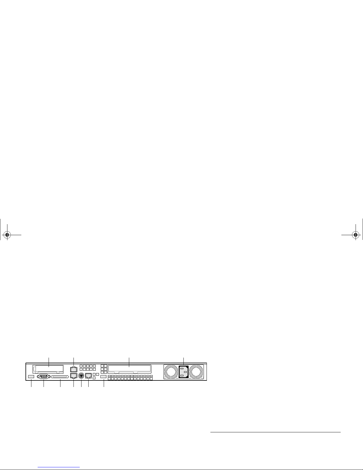
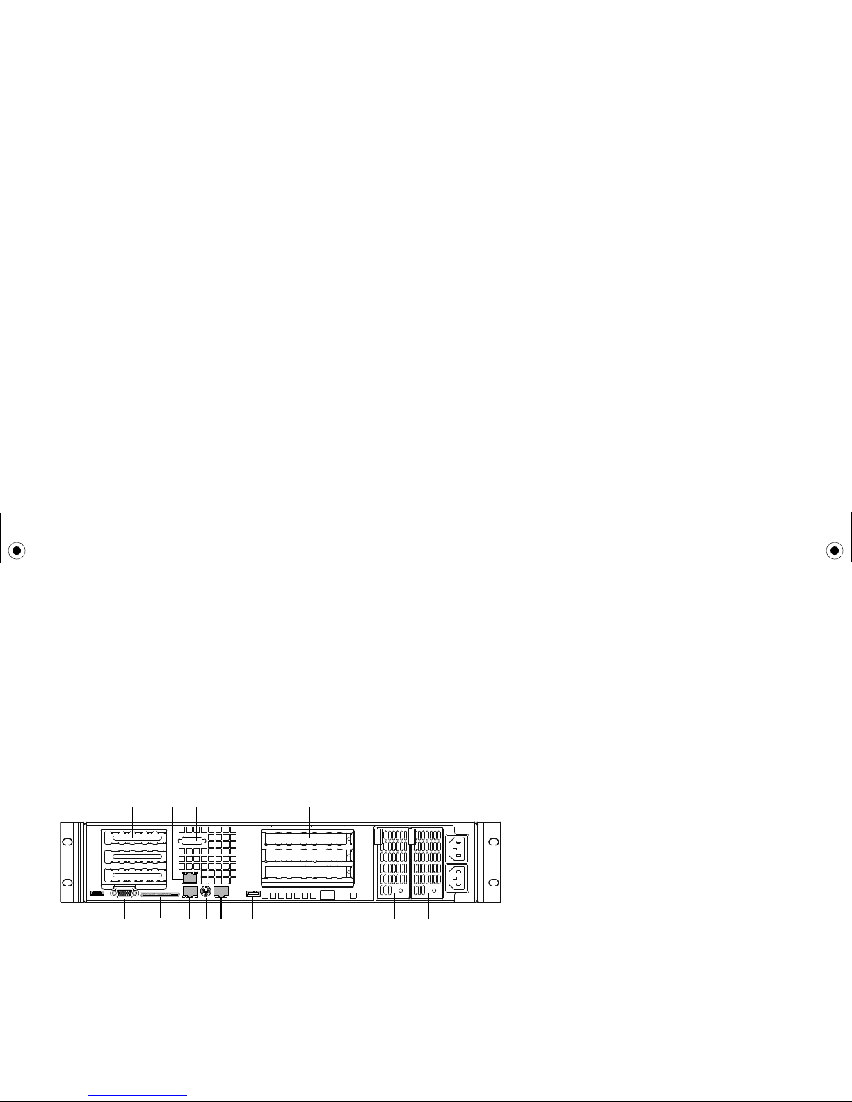
Table 2 and Figure 2 identify the connectors on the back panel of your chassis.
Figure 2. NF1610 Back Panel Connector Layout
A B
K J I H G F E
CD
Table 2: NF1610 Back Panel Connectors
A
PCI card bracket (low-profile)
B
RJ-45 NIC 2 connector
C
PCI card bracket (full-length)
D
Power supply
E
USB connector
F
RJ-45 serial port
G
PS/2 mouse/keyboard connector
H
RJ-45 NIC 1 connector
I
SCSI channel A connector (SCSI only)
J
Video connector
K
USB connector
MAS001426-02.book Page 5 Monday, May 19, 2003 2:45 PM
NF1610 SYSTEM FEATURES
NF1610 Front Control Panel
2-6
2
. . . . . . . . . . . . . . . . . . . . . . . . . . . . . . . . . . . . . . . . . . . . . . . . . . . . . . . . . . . . . . . . . . .
NF1610 FRONT CONTROL PANEL
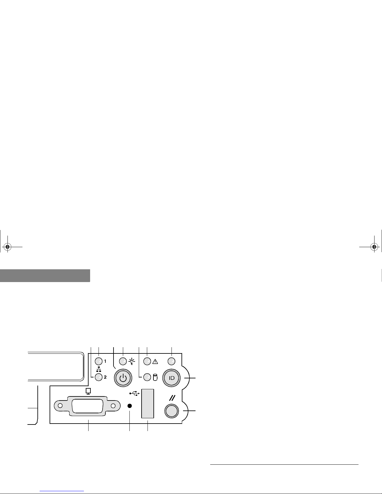
Table 3 and Figure 3 identify the buttons and LEDs on the front control panel.
NF1610 Front Control Panel View
Figure 3. NF1610 Front Contr ol Panel Component Layout
L JK
H
I
BA F GEDC
Table 3: NF1610 Front Control Panel Components
A
NIC 2 activity LED
B
NIC 1 activity LED
C
Power/sleep button
D
Power/sleep LED
E
Hard disk drive status LED
F
System status LED
G
ID LED
H
ID button
I
Reset button
J
USB connector
K
Non-maskable interrupt (NMI) button
L
Video connector
MAS001426-02.book Page 6 Monday, May 19, 2003 2:45 PM
NF1610 SYSTEM FEATU RES
NF1610 Front Control Panel
2-7
. . . . .
NF1610 Control Button Description
Table 4 describes the control button functions which are located on your server’s front control
panel. T o view the front control panel features, refer to NF1610 Front Control Panel View on page
2-6.
Table 4: NF16 10 Control Button Descri ption s
Button
Description
Power/Sleep Button
This button toggles the system power on and off. The sleep button is for ACPI-compatible operating
systems.
ID Button
This button toggles the front panel ID LED and the system board ID LED on and off. The system board ID
LED is visible from the rear of the chassis and allows you to locate the server you are working on from
behind a rack of servers.
Reset Button
This button reboots and initial iz es the sy st em.
NMI Button
When you press the recessed button with a paper clip or pin, the system issues a non-maskable interrupt
and puts the server into a halt state for diagnostic purposes.
MAS001426-02.book Page 7 Monday, May 19, 2003 2:45 PM

NF1610 SYSTEM FEATURES
NF1610 Front Control Panel
2-8
2
NF1610 Front Control Panel LED Description
Table 5 describes the LEDs located on your server’s front control panel. To view the front control
panel features, refer to NF1610 Front Control Panel View on page 2-6.
Table 5: NF1610 Front Control Panel LED Description
LED
Description
NIC 1 Activity LED
NIC 2 Activity LED
A continuous green light indicates a link between the system and the network to which it is connected. A
blinking green light indicates network activity.
Power/Sleep LED
A continuous green light indicates the system has power applied to it. A blinking green lighta indicates the
system is sleeping. No light indicates the system does not have power applied to it (other than 5 V standby
power).
a. The power LED sleep indication is maintained on standby by the chipse t. If the system is turned off without going thr ough the BIOS, the LED state in effect at the time
the power turned off will be res tored when the system is turned on u n ti l th e BIOS clears it. If the system is not tu rn ed of f normally, it is possible that the power LED will
be blinking at the same time that the syst em sta tus LE D is off due to a failu re or configuration change that prevents the B IO S from r unni ng.
Hard Disk Drive
Status LED
A random blinking green light indicates hard disk drive activity (SCSI or IDE). A continuous amber light
indicates hard disk drive fault (SCSI or IDE). No light
b
indicates no hard disk drive activity nor fault (SCSI or
IDE).
b. This light is al s o o ff when the system is turned off or in a sleep state.
System Status
LED
A continuous green light indicates the system is operating normally. A blinking green light indicates the
system is operating in a degr aded co ndition. A co ntinuo us amb er light
c
indicates the system is in a criti cal or
nonrecoverable condition. A blinking amber light indicates the system is in a noncritical condition. No light
indicates POST/system stop.
c. The amber status take s pre cede n c e over the gr een status. When the amber LED is on or blinking, th e green LED is off.
ID LED
A continuous blue light indicates ID button is depressed or light is turned on by software. No light indicates
ID button is not depressed.
MAS001426-02.book Page 8 Monday, May 19, 2003 2:45 PM
NF1610 SYSTEM FEATU RES
NF1610 Top Panel
2-9
. . . . .
. . . . . . . . . . . . . . . . . . . . . . . . . . . . . . . . . . . . . . . . . . . . . . . . . . . . . . . . . . . . . . . . . . .
NF1610 TOP PANEL
NF1610 Top Panel View
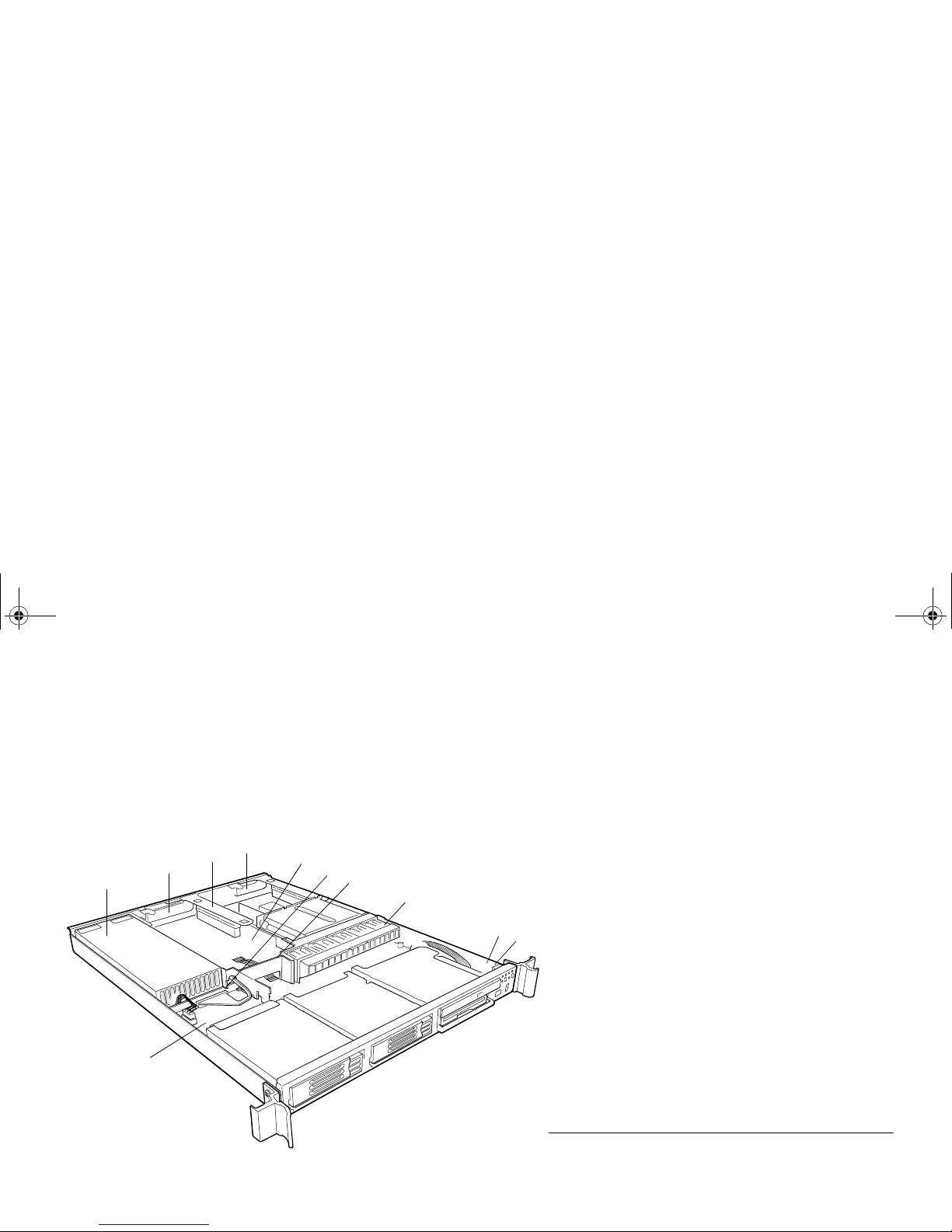
Table 6 and Figure 4 identify the connectors on the top panel of your server chassis.
Figure 4. NF1610 Top Panel Component Layout
D
A
C
I
E
F
B
K
H
J
G
Table 6: NF1610 Top Panel Components
A
Power supply
B
PCI card bracket (full-height)
C
Riser card assembly
D
PCI card bracket (low-profile)
E
System Board
F
Power distribution board
G
Air baffle
H
Fan module
I
Front panel board
J
Intrusion switch
K
Backplane board
MAS001426-02.book Page 9 Monday, May 19, 2003 2:45 PM

NF1610 SYSTEM FEATURES
NF1610 Top Panel
2-10
2
MAS001426-02.book Page 10 Monday, May 19, 2003 2:45 PM

3-11
.
. .
. .
. . . . . . . . . . . . . . . . . . . . . . . . . . . . . . . . . . .
NF2610 S
YSTEM
F
EATURES
3
The following chapter provides information about the components and connectors on your
server.
Note
. . . . . . . . . . . . . . . . . . . . . . . . . . . . . . . . . . . . . . . . . . .
. . . . . . . . . . . . . . . . . . . . . . . . . . . . . . . . . . . . . . . . . . .
The appearance, location, and existence of the components mentioned may vary by model.
MAS001426-02.book Page 11 Monday, May 19, 2003 2:45 PM
NF2610 SYSTEM FEATURES
NF2610 Front Panel
3-12
3
. . . . . . . . . . . . . . . . . . . . . . . . . . . . . . . . . . . . . . . . . . . . . . . . . . . . . . . . . . . . . . . . . . .
NF2610 FRONT PANEL
NF2610 Front Panel View
Table 7 and Figure 5 identify the features on the front of your server.
Figure 5. NF2610 Front Panel Component Layout
A B C D E
G
F
Table 7: NF2610 Front Panel Components
A
Chassis handle
B
Drive bay (1-inch)
C
HDD activity/fault indicator
D
Flex bay (optional DVD/CD-ROM drive/FDD
module shown)
E
Front Control Panel (for more information
refer to “NF2610 Front Control Panel” on
page 3-14)
F
Chassis handle
G
Tape drive bay
MAS001426-02.book Page 12 Monday, May 19, 2003 2:45 PM
NF2610 SYSTEM FEATU RES
NF2610 Back Panel
3-13
. . . . .
. . . . . . . . . . . . . . . . . . . . . . . . . . . . . . . . . . . . . . . . . . . . . . . . . . . . . . . . . . . . . . . . . . .
NF2610 BACK PANEL
NF2610 Back Panel View
Table 8 and Figure 6 identify the connectors on the back panel of your chassis.
Figure 6. NF2610 Back Panel Connector Layout
A CB D E
FGHIJL KMON
Table 8: NF2610 Back Panel Connectors
A
PCI card bracket (low-profile)
B
RJ-45 NIC 2 connector
C
Serial A port mounting (cable not
provided)
D
PCI card bracket (full-length)
E
AC power input (primary)
F
AC power input (redundant)
G
Power supply module, redundant
H
Power supply module, primary
I
USB connector
J
RJ-45 serial port
K
PS/2 mouse/keyboard connector
L
RJ-45 NIC 1 connector
M
SCSI channel A connector
N
Video controller
O
USB connector
MAS001426-02.book Page 13 Monday, May 19, 2003 2:45 PM

NF2610 SYSTEM FEATURES
NF2610 Front Control Panel
3-14
3
. . . . . . . . . . . . . . . . . . . . . . . . . . . . . . . . . . . . . . . . . . . . . . . . . . . . . . . . . . . . . . . . . . .
NF2610 FRONT CONTROL PANEL
Table 9 and Figure 7 identify the buttons and LEDs on the front control panel.
NF2610 Front Control Panel View
Figure 7. NF2610 Front Contr ol Panel Component Layout
L JK
H
I
BA F GEDC
Table 9: NF2610 Front Control Panel Components
A
NIC 2 activity LED
B
NIC 1 activity LED
C
Power/sleep button
D
Power/sleep LED
E
Hard disk drive status LED
F
System status LED
G
ID LED
H
ID button
I
Reset button
J
USB connector
K
Non-maskable interrupt (NMI) button
L
Video connector
MAS001426-02.book Page 14 Monday, May 19, 2003 2:45 PM

NF2610 SYSTEM FEATU RES
NF2610 Front Control Panel
3-15
. . . . .
NF2610 Control Button Description
Table 10 describes the control button functions which are located on your server’s front control
panel. T o view the front control panel features, refer to NF2610 Front Control Panel View on page
3-14.
Table 10: NF2610 Control Button Descriptions
Button
Description
Power/Sleep Button
This button toggles the system power on and off. The sleep button is for ACPI-compatible operating
systems.
ID Button
This button toggles the front panel ID LED and the system board ID LED on and off. The system board ID
LED is visible from the rear of the chassis and allows you to locate the server you are working on from
behind a rack of servers.
Reset Button
This button reboots and initial iz es the sy st em.
NMI Button
When you press the recessed button with a paper clip or pin, the system issues a non-maskable interrupt
and puts the server into a halt state for diagnostic purposes.
MAS001426-02.book Page 15 Monday, May 19, 2003 2:45 PM

NF2610 SYSTEM FEATURES
NF2610 Front Control Panel
3-16
3
NF2610 Front Control Panel LED Description
Table 1 1 describes the LEDs located on your server’s front control panel. To view the front control
panel features, refer to NF2610 Front Control Panel View on page 3-14.
Table 11: NF2610 Front Control Panel LED Description
LED
Description
NIC 1 Activity LED
NIC 2 Activity LED
A continuous green light indicates a link between the system and the network to which it is connected.
A blinking green light indicates network activity.
Power/Sleep LED
A continuous green light indicates the system has power applied to it. A blinking green lighta indicates the
system is sleeping. No light indicates the system does not have power applied to it (other than 5 V standby
power).
a. The power LED sleep indic a tion is maintained on standby by the chipset. If the system is turned off witho ut going through the BIOS, the LED state in effect at the time
the power turned off will be res tored when the system is turned on u n ti l th e BIOS clears it. If the system is not tu rn ed of f normally, it is possible that the power LED will
be blinking at the same time that the syst em sta tus LE D is off due to a failu re or configuration change that prevents the B IO S from r unni ng.
Hard Disk Drive
Status LED
A random blinking green light indicates hard disk drive activity. A continuous amber light indicates hard disk
drive fault. No light
b
indicates no hard disk drive activity nor fault.
b. This light is al s o o ff when the system is turned off or in a sleep state.
System Status
LED
A continuous green light indicates the system is operating normally. A blinking green light indicates the
system is operating in a degr aded co ndition. A co ntinuo us amb er light
c
indicates the system is in a criti cal or
nonrecoverable condition. A blinking amber light indicates the system is in a noncritical condition. No light
indicates POST/system stop.
c. The amber status take s pre cede n c e over the gr een status. When the amber LED is on or blinking, th e green LED is off.
ID LED
A continuous blue light indicates ID button is depressed or light is turned on by software. No light indicates
ID button is not depressed.
MAS001426-02.book Page 16 Monday, May 19, 2003 2:45 PM
 Loading...