

MPC ATD-313186 User Manual

®
ATD Actuator
Automatic Door Drive
Model 50 ATD-313186
Operating and Installation Instructions
Milwaukee Protective Covers
2300 South Calhoun Road
New Berlin, WI 53151
Phone: 414-906-4000
Fax: 414-906-4100
© 1998 Milwaukee Protective Covers
V2.0
www.MPCovers.com

ATD 50 Actuator® Operating Instructions
Contents
1 Explanation of symbols .................................................4
2 General Safety Instructions ..........................................4
2.1 Correct Use .....................................................................5
2.2 Design and Installation Personnel Requirements.....5
2.3 General Information and MPC™ Liability...................5
3 Theory of Operation.......................................................6
4 Design Information.........................................................7
4.1 Mechanical ......................................................................7
4.1.1 The Door..........................................................................7
4.1.2 Installation Position........................................................7
4.1.3 Installation.......................................................................8
4.2 Electrical..........................................................................9
4.2.1 Main Power Connection................................................9
4.2.2 Control Connection ..................................................... 10
5 Start-up Procedure...................................................... 10
5.1 Preparation................................................................... 10
5.2 Start-up ......................................................................... 11
6 Check List for Functional Tests................................. 11
7 Error Diagnosis............................................................ 13
8 Hardware Error Displays ............................................ 14
9 Standard Input Functions ........................................... 15
10 Standard Output Functions ........................................ 17
3811 N. Holton Street • Milwaukee, WI • 53212 •USA • Phone • 414-906-4000 • Fax 414-906-4100 • www.MPCovers.com
Page 2

ATD 50 Actuator® Operating Instructions
11 Operation...................................................................... 19
11.1 Calibration Run............................................................ 19
11.2 Door Movements......................................................... 20
11.3 Reversing Motion........................................................ 20
12 Memory and System Layout...................................... 21
13 Technical Data.............................................................. 22
14 Electrical Wiring Diagram........................................... 24
15 Physical Dimensions................................................... 25
16 Trouble Shooting Guide......................................... 26
3811 N. Holton Street • Milwaukee, WI • 53212 •USA • Phone • 414-906-4000 • Fax 414-906-4100 • www.MPCovers.com
Page 3

1 Explanation of symbols
This symbol warns of general hazards and of possible damage to the equipment.
This symbol warns of dangerous electrical voltages or current
2 General Safety Instructions
ATD 50 Actuator® Operating Instructions
Before beginning installation or start-up, read and follow these
instructions. Damage to the unit and personal injury may result
from not following these instructions.
Keep fingers away from all moving parts. Be especially careful to install guards or shield
to protect personnel from the moving drive belt and pulleys.
• Be sure the electrical power is disconnected and locked-out when working
on the ATD 50 Actuator
• Install the electrical cables and power only after the mechanical installation of the
unit.
• Turn on the power to the ATD 50 Actuator® only after all internal cables are
connected. Do not connect cables while the unit is powered.
• Always use the correct tools for installation and repair.
®
.
3811 N. Holton Street • Milwaukee, WI • 53212 •USA • Phone • 414-906-4000 • Fax 414-906-4100 • www.MPCovers.com
Page 4

2.1 Correct Use
The ATD 50 Actuator® is designed for operating automatic doors on machine tools
and industrial equipment. It is intended to automatically open and close doors,
detect obstructions, and hold the door when closed. Vertical doors must be
installed using a counter-weight system since the ATD 50 Actuator® is not intended
to lift or hold the weight of a door.
Any other use for the ATD 50 Actuator® is the judgement and risk of the installer.
The brake on the ATD 50 Actuator® is intended to help prevent
accidental opening of the door. The brake is not an absolute
positive lock and can be overcome by a strong pull of the door.
The machine designer and/or installer must decide if additional
positive latches are required to insure proper machine safety.
ATD 50 Actuator® Operating Instructions
Use the ATD 50 Actuator® system only when it is operating properly and as
designed. Any problems or malfunctions should be repaired immediately. The
safety systems of the ATD 50 Actuator® unit depend upon correct operation.
2.2 Design and Installation Personnel Requirements
The design and installation of the guard door system, including the ATD 50
Actuator® must be completed by qualified personnel with training and experience in
the area of power-operated doors. The personnel must be familiar with relevant
work safety regulations, accident prevention guidelines, and generally accepted
technical practices.
2.3 General Information
The operating, maintenance, and installation instructions provided by Milwaukee
Protective Covers must be observed. The drive must be maintained and repaired
only by qualified technicians who are familiar with the ATD 50 Actuator® and have
been instructed about the possible dangers.
2.3 continued on next page
3811 N. Holton Street • Milwaukee, WI • 53212 •USA • Phone • 414-906-4000 • Fax 414-906-4100 • www.MPCovers.com
Page 5

2.3 General Information (cont.)
The purchaser, designer, and/or installer is responsible to insure the correct and
safe application of the ATD 50 Actuator®. These personnel must insure that all
Federal, State, and Local laws and regulations regarding workplace safety are
observed. OSHA and other safety regulations must be observed when completing
an installation.
Milwaukee Protective Covers is not responsible for incidental and/or consequential
damages resulting from the use or application of the ATD 50 Actuator®. Our
maximum liability under warranty is for only the cost of the product sold. Milwaukee
Protective Covers makes no claims for merchantability or fitness of use for specific
machine guarding applications. The purchaser, designer, and/or installer of the
ATD 50 Actuator® must decide if the drive is applicable to a given machine
application. In addition, Milwaukee Protective Covers specifically declines any
responsibility for damage or injury resulting from unauthorized changes to the drive,
including software parameter changes. No employee of Milwaukee Protective
Covers is authorized to modify this warranty without the specific written approval of
a company officer.
ATD 50 Actuator® Operating Instructions
3 Theory of Operation
The ATD 50 Actuator® is controlled using a built-in microprocessor computer. The
microprocessor is programmed to provide optimum motion control and safe
response to obstructions. Internal parameters can be changed by authorized
service personnel to customize the installation. The software can be modified for
each installation.
®
The ATD 50 Actuator
automatically adjusts to the opening width of the machine. During the OPEN and
CLOSE motion, the unit finds the end-stop positions of the door. Therefore, the
door width is not limited in any way.
The internal drive motor is operated by a variable frequency converter which
provides the optimal speed and torque for each movement. The motor speed and
torque are continuously monitored thereby providing a sensitive and accurate
electronic reversing feature ( see Section 11.3).
is completely self-calibrating. Upon power-up, the unit
3811 N. Holton Street • Milwaukee, WI • 53212 •USA • Phone • 414-906-4000 • Fax 414-906-4100 • www.MPCovers.com
Page 6

4 Design Information
4.1 Mechanical
All components in the system must be designed and installed to withstand the
forces produced by the system. This includes the door itself, all mounting brackets,
the idler pulley, the connector between the door and belt, and the door end stops.
Maximum tensile force of the belt 30 lbs (130 N)
Weight of the ATD 50 Actuator® unit 31 lbs (14Kg)
4.1.1 The Door
The door must have fixed positive stops at each end of travel. The stops must be
able to withstand the maximum pressure of the driving force (30 lbs /130 N).
ATD 50 Actuator® Operating Instructions
Smooth door movement is the most important criteria to insure correct operation.
The door should have a consistent drag force over its complete travel. The door
guides should provide as low a drag resistance as possible. This will insure
trouble-free operation and will increase the drives’ sensitivity to any obstructions.
4.1.2 Installation Position
The ATD 50 Actuator® can be installed in any position and any orientation
according to the specific application. The drive belt, idler pulley, and ATD 50
Actuator® should be installed so that the moving parts do not touch or rub on any
other part of the machine. Also, the drive pulley and idler must be properly aligned
to insure correct belt travel. Failure to align the drive belt properly will result in
excessive belt wear and shortened belt life.
The ATD 50 Actuator® unit and the drive belt should be installed outside the area of
contamination. If the unit must be installed inside the area of contamination, the
drive belt must be protected from chips, coolants, or other debris.
3811 N. Holton Street • Milwaukee, WI • 53212 •USA • Phone • 414-906-4000 • Fax 414-906-4100 • www.MPCovers.com
Page 7

ATD 50 Actuator® Operating Instructions
4.1.3 Installation
The ATD 50 Actuator® internal frame is mounted into the metal enclosure with 6
screws. (There are two screws on the back of the unit and four button-head cap
screws on the top.) For installation, only the four screws on the top OR the two
screws on the back should be used.
Never loosen all 6 screws at the same time! Otherwise the internal frame will be
loose inside the metal housing. If the internal frame is allowed to move inside the
metal housing, the drive shaft can be damaged by scraping against the sealing
elements.
Under no circumstances should the large hexagonal screw on the drive pulley
be loosened!
3811 N. Holton Street • Milwaukee, WI • 53212 •USA • Phone • 414-906-4000 • Fax 414-906-4100 • www.MPCovers.com
Page 8
4.2 Electrical
ATD 50 Actuator® Operating Instructions
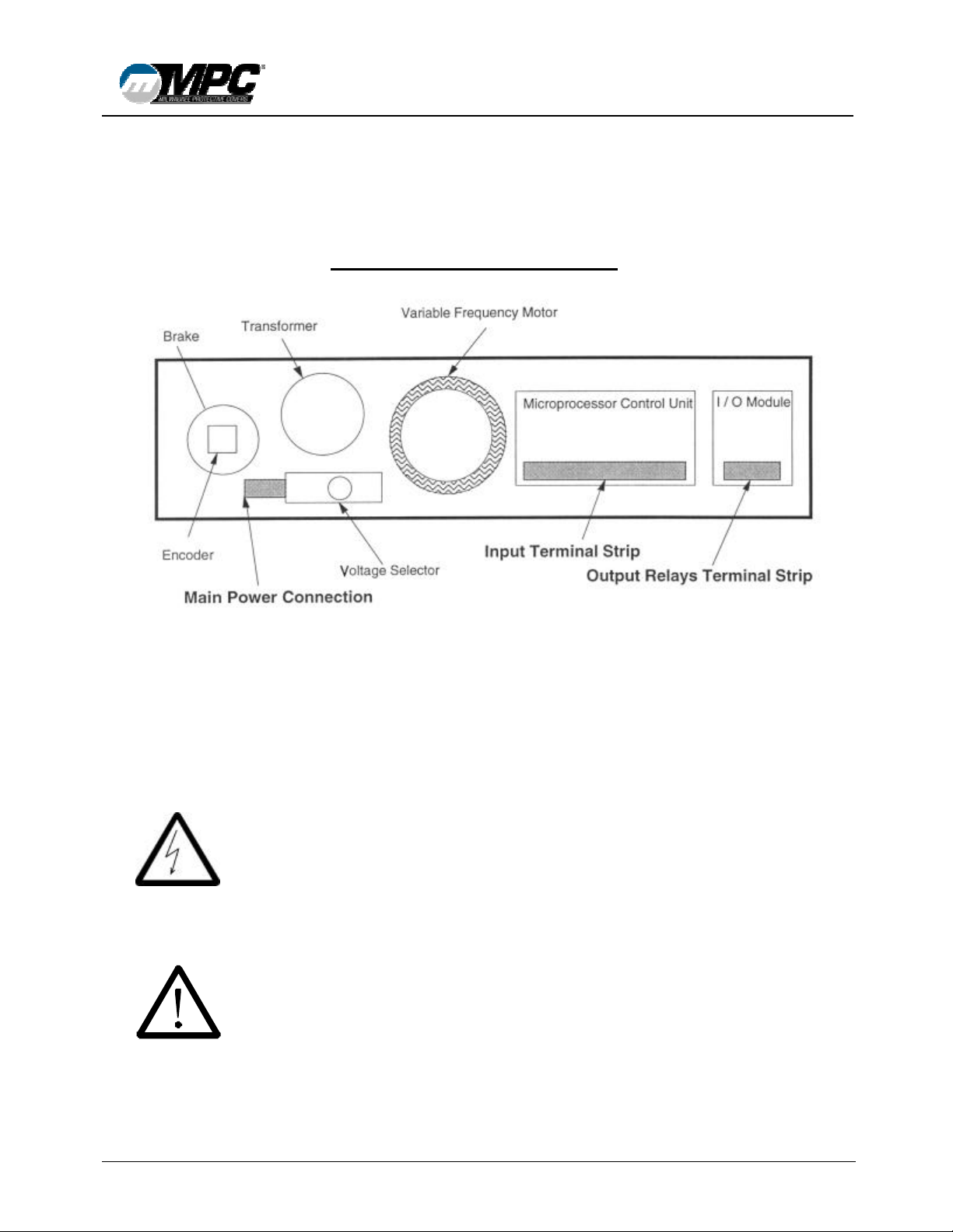
Internal View of ATD 50 Actuator¨
4.2.1 Main Power Connection
The main power supply can be switched between 115 volts and 230 volts and with 50
or 60 Hz AC power. There is an internal switch on the main power connection to
select 115V or 230V.
The main power must be externally protected with a 10 amp fast-blow fuse and
a system disconnect.
Verify that the power selection switch is set to the correct voltage before start-up!
3811 N. Holton Street • Milwaukee, WI • 53212 •USA • Phone • 414-906-4000 • Fax 414-906-4100 • www.MPCovers.com
Page 9
 Loading...