


MOTU M64 operation manual
M64
User Guide
Title Page
™
1280 Massachusetts Avenue
Cambridge, MA 02138
Business voice: (617) 576-2760
Business fax: (617) 576-3609
Web site: www.motu.com
Tech support: www.motu.com/support

SAFETY PRECAUTIONS AND ELECTRICAL REQUIREMENTS FOR THE M64 (“PRODUCT”)
CAUTION! READ THIS SAFETY GUIDE BEFORE YOU BEGIN INSTALLATION OR OPERATION. FAILURE TO COMPLY WITH SAFETY
INSTRUCTIONS COULD RESULT IN BODILY INJURY OR EQUIPMENT DAMAGE.
HAZARDOUS VOLAGES: CONTACT MAY CAUSE ELECTRIC SHOCK OR BURN. TURN OFF UNIT BEFORE SERVICING.
WARNING: TO REDUCE THE RISK OF FIRE OR ELECTRICAL SHOCK, DO NOT EXPOSE THIS APPLIANCE TO RAIN OR OTHER MOISTURE.
CAUTION: TO REDUCE THE RISK OF ELECTRICAL SHOCK, DO NOT REMOVE COVER. NO USER-SERVICEABLE PARTS INSIDE. REFER SERVICING
TO QUALIFIED SERVICE PERSONNEL.
IMPORTANT SAFEGUARDS
1. Read these instructions. All the safety and operating instructions should be read before operating the product.
2. Keep these instructions. These safety instructions and the product owner’s manual should be retained for future reference.
3. Heed all warnings. All warnings on the product and in the owner’s manual should be adhered to.
4. Follow all Instructions. All operating and use instructions should be followed.
5. Do not use the product near water.
6. Cleaning - Unplug the product from the computer and clean only with a dry cloth. Do not use liquid or aerosol cleaners.
7. Ventilation - Do not block any ventilation openings. Install in accordance with the manufacturer’s instructions.
8. Heat - Do not install the product near any heat sources such as radiators, heat registers, stoves, or another apparatus (including an amplifier)
that produces heat.
9. Overloading - Do not overload wall outlets and extension cords as this can result in a risk of fire or electrical shock.
10.Power supply cord - Protect the product power supply cord from being walked on or pinched by items placed upon or against them.
11.Power switch - Install the product so that the power switch can be accessed and operated at all times.
12.Disconnect - The main power supply plug is considered to be the disconnect device for the product and shall remain readily operable.
13.Accessories - Only use attachments/accessories specified by the manufacturer.
14.Surge protection - Unplug the product during lightning storms or when unused for long periods of time.
15.Servicing - Refer all servicing to qualified service personnel. Servicing is required when the product has been damaged in any way, such as
when a power-supply cord or plug is damaged, liquid has been spilled or objects have fallen into the product, the product has been exposed
to rain or moisture, does not operate normally, or has been dropped.
16.Power Sources - Refer to the manufacturer’s operating instructions for power requirements.
17.Installation - Do not install the product in an unventilated rack, or directly above heat-producing equipment such as power amplifiers. Observe
the maximum ambient operating temperature listed below.
18.Power amplifiers- Never attach audio power amplifier outputs directly to any of the unit’s connectors.
19.Replacement Parts - When replacement parts are required, be sure the service technician has used replacement parts specified by the
manufacturer or have the same characteristics as the original part. Unauthorized substitutions may result in fire, electric shock or other
hazards.
20.Safety Check - Upon completion of any service or repairs to this MOTU product, ask the service technician to perform safety checks to
determine that the product is in safe operating conditions.
ENVIRONMENT, HEAT AND VENTILATION
Operating Temperature: 10°C to 40°C (50°F to 104°). The product should be situated away from heat sources or other equipment that produces
heat. When installing the product in a rack or any other location, be sure there is adequate space around the product to ensure proper ventilation.
Improper ventilation will cause overheating and can damage the unit.
TO REDUCE THE RISK OF ELECTRICAL SHOCK OR FIRE
Do not handle the power supply with wet hands. Do not pull on the power supply cord when disconnecting it from an AC wall outlet. Grasp it by
the plug. Do not expose this apparatus to rain or moisture. Do not place objects containing liquids on it.
DC INPUT
10 - 24V DC • 1.0A max

Contents
Part 1: Getting Started
7
Quick Start Guide
M64 Front Panel
9
10
M64 Rear Panel
MOTU Pro Audio Control Web App
11
About the M64
23
Packing List and System Requirements
27
29
Software Installation
Hardware Installation
33
Part 2: Using the M64
49
Presets
The Front Panel LCD
53
Working with Host Audio Software
55
63
Mixer Effects
MOTU Audio Tools
71
87
Networking
Part 3: Appendices
Troubleshooting
95
Audio Specifications
97
99
Mixer Schematics
Updating Firmware
103
105
OSC Support
Index
107
III

About the Mark of the Unicorn License Agreement and
Limited Warranty on Software
TO PERSONS WHO PURCHASE OR USE THIS PRODUCT: carefully read all the
terms and conditions of the “click-wrap” license agreement presented to you when
you install the software. Using the software or this documentation indicates your
acceptance of the terms and conditions of that license agreement.
Mark of the Unicorn, Inc. (“MOTU”) owns both this program and its documentation.
Both the program and the documentation are protected under applicable copyright,
trademark, and trade-secret laws. Your right to use the program and the
documentation are limited to the terms and conditions described in the license
agreement.
Reminder of the terms of your license
This summary is not your license agreement, just a reminder of its terms. The actual
license can be read and printed by running the installation program for the software.
That license agreement is a contract, and clicking “Accept” binds you and MOTU to
all its terms and conditions. In the event anything contained in this summary is
incomplete or in conflict with the actual click-wrap license agreement, the terms of the
click-wrap agreement prevail.
YOU MAY: (a) use the enclosed program on a single computer; (b) physically transfer
the program from one computer to another provided that the program is used on only
one computer at a time and that you remove any copies of the program from the
computer from which the program is being transferred; (c) make copies of the
program solely for backup purposes. You must reproduce and include the copyright
notice on a label on any backup copy.
YOU MAY NOT: (a) distribute copies of the program or the documentation to others;
(b) rent, lease or grant sublicenses or other rights to the program; (c) provide use of
the program in a computer service business, network, time-sharing, multiple CPU or
multiple user arrangement without the prior written consent of MOTU; (d) translate,
adapt, reverse engineer, decompile, disassemble, or otherwise alter the program or
related documentation without the prior written consent of MOTU.
MOTU warrants to the original licensee that the disk(s) on which the program is
recorded be free from defects in materials and workmanship under normal use for a
period of ninety (90) days from the date of purchase as evidenced by a copy of your
receipt. If failure of the disk has resulted from accident, abuse or misapplication of the
product, then MOTU shall have no responsibility to replace the disk(s) under this
Limited Warranty.
THIS LIMITED WARRANTY AND RIGHT OF REPLACEMENT IS IN LIEU OF,
AND YOU HEREBY WAIVE, ANY AND ALL OTHER WARRANTIES, BOTH
EXPRESS AND IMPLIED, INCLUDING BUT NOT LIMITED TO WARRANTIES
OF MERCHANTABILITY AND FITNESS FOR A PARTICULAR PURPOSE. THE
LIABILITY OF MOTU PURSUANT TO THIS LIMITED WARRANTY SHALL BE
LIMITED TO THE REPLACEMENT OF THE DEFECTIVE DISK(S), AND IN NO
EVENT SHALL MOTU OR ITS SUPPLIERS, LICENSORS, OR AFFILIATES BE
LIABLE FOR INCIDENTAL OR CONSEQUENTIAL DAMAGES, INCLUDING
BUT NOT LIMITED TO LOSS OF USE, LOSS OF PROFITS, LOSS OF DATA OR
DATA BEING RENDERED INACCURATE, OR LOSSES SUSTAINED BY THIRD
PARTIES EVEN IF MOTU HAS BEEN ADVISED OF THE POSSIBILITY OF
SUCH DAMAGES. THIS WARRANTY GIVES YOU SPECIFIC LEGAL RIGHTS
WHICH MAY VARY FROM STATE TO STATE. SOME STATES DO NOT ALLOW
THE LIMITATION OR EXCLUSION OF LIABILITY FOR CONSEQUENTIAL
DAMAGES, SO THE ABOVE LIMITATION MAY NOT APPLY TO YOU.
Update Policy
In order to be eligible to obtain updates of the program, you must complete and return
the attached Mark of the Unicorn Purchaser Registration Card to MOTU.
Copyright Notice
Copyright © 2017 by Mark of the Unicorn, Inc. All rights reserved. No part of this
publication may be reproduced, transmitted, transcribed, stored in a retrieval system,
or translated into any human or computer language, in any form or by any means
whatsoever, without express written permission of Mark of the Unicorn, Inc., 1280
Massachusetts Avenue, Cambridge, MA, 02138, U.S.A.
Limited Warranty on Hardware
Mark of the Unicorn, Inc. and S&S Research (“MOTU/S&S”) warrant this equipment
against defects in materials and workmanship for a period of TWO (2) YEARS from
the date of original retail purchase. This warranty applies only to hardware products;
MOTU software is licensed and warranted pursuant to separate written statements.
If you discover a defect, first write or call Mark of the Unicorn at (617) 576-2760 to
obtain a Return Merchandise Authorization Number. No service will be performed on
any product returned without prior authorization. MOTU will, at its option, repair or
replace the product at no charge to you, provided you return it during the warranty
period, with transportation charges prepaid, to Mark of the Unicorn, Inc., 1280
Massachusetts Avenue, MA 02138. You must use the product’s original packing
material for in shipment, and insure the shipment for the value of the product. Please
include your name, address, telephone number, a description of the problem, and
the original, dated bill of sale with the returned unit and print the Return Merchandise
Authorization Number on the outside of the box below the shipping address.
This warranty does not apply if the equipment has been damaged by accident,
abuse, misuse, or misapplication; has been modified without the written permission
of MOTU, or if the product serial number has been removed or defaced.
ALL IMPLIED WARRANTIES, INCLUDING IMPLIED WARRANTIES OF
MERCHANTABILITY AND FITNESS FOR A PARTICULAR PURPOSE, ARE
LIMITED IN DURATION TO TWO (2) YEARS FROM THE DATE OF THE
ORIGINAL RETAIL PURCHASE OF THIS PRODUCT.
THE WARRANTY AND REMEDIES SET FORTH ABOVE ARE EXCLUSIVE
AND IN LIEU OF ALL OTHERS, ORAL OR WRITTEN, EXPRESS OR IMPLIED.
No MOTU/S&S dealer, agent, or employee is authorized to make any modification,
extension, or addition to this warranty.
MOTU/S&S ARE NOT RESPONSIBLE FOR SPECIAL, INCIDENTAL, OR
CONSEQUENTIAL DAMAGES RESULTING FROM ANY BREACH OF
WARRANTY, OR UNDER ANY LEGAL THEORY, INCLUDING LOST PROFITS,
DOWNTIME, GOODWILL, DAMAGE OR REPLACEMENT OF EQUIPMENT
AND PROPERTY AND COST OF RECOVERING REPROGRAMMING, OR
REPRODUCING ANY PROGRAM OR DATA STORED IN OR USED WITH
MOTU/S&S PRODUCTS.
Some states do not allow the exclusion or limitation of implied warranties or liability for
incidental or consequential damages, so the above limitation or exclusion may not
apply to you. This warranty gives you specific legal rights, and you may have other
rights which vary from state to state.
MOTU, Digital Performer, AudioDesk, Mark of the Unicorn and the unicorn silhouette
logo are trademarks of Mark of the Unicorn, Inc.
Thunderbolt and the Thunderbolt logo are trademarks of Intel Corporation in the U.S.
and/or other countries.
This equipment has been type tested and found to comply with the limits for a class B digital device,
pursuant to Part 15 of the FCC Rules. These limits are designed to provide reasonable protection
against harmful interference in a residential installation. This equipment generates, uses, and can
radiate radio frequency energy and, if not installed and used in accordance with the instruction manual,
may cause harmful interference to radio communications. However, there is no guarantee that
interference will not occur in a particular installation. If this equipment does cause interference to radio
or television equipment reception, which can be determined by turning the equipment off and on, the
user is encouraged to try to correct the interference by any combination of the following measures:
• Relocate or reorient the receiving antenna
• Increase the separation between the equipment and the receiver
• Plug the equipment into an outlet on a circuit different from that to which the receiver is connected
If necessary, you can consult a dealer or experienced radio/television technician for additional
assistance.
PLEASE NOTE: only equipment certified to comply with Class B (computer input/output devices,
terminals, printers, etc.) should be attached to this equipment, and it must have shielded interface
cables in order to comply with the Class B FCC limits on RF emissions.
WARNING: changes or modifications to this unit not expressly approved by the party
responsible for compliance could void the user's authority to operate the equipment.

Part 1
Getting Started

Quick Start Guide
CHAPTER
Thank you for purchasing an M64! Follow these
easy steps to get started quickly.
1
Download and run the
Installer
found here:
MOTU Pro Audio
http://www.motu.com/avb
2
(Optional) For quick access to the M64 from
your iPad or iPhone, download the MOTU
Discovery app from the Apple App Store.
Your iPhone and iPad must be on the same
☛
Wi-Fi network as your computer.
3
Connect the interface to your computer with a
USB cable (included). If you have a Thunderboltequipped Mac running OS X El Capitan (10.11) or
later, you can alternately connect the M64 to the
Mac’s Ethernet port with a standard CAT-5e or
CAT-6 Ethernet cable (sold separately).
4
Switch on the M64.
5
Open the
MOTU Pro Audio Control
web app by
doing one of the following:
For advanced network options, and device
■
discovery from any modern browser, see
chapter 10, “Networking” (page 87).
Mac
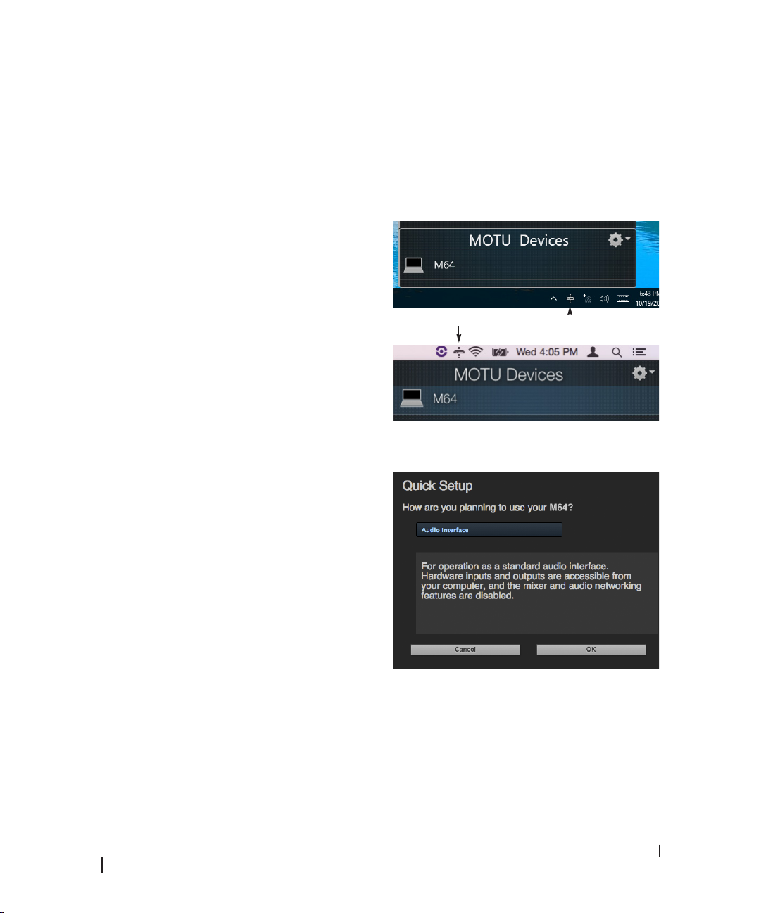
6
Choose a preset from Quick Setup.
Windows
■
Choose the M64 from the MOTU Discovery app
menu (found in the Mac menu bar or Windows
taskbar).
■
Alternately, you can launch the
WebUI Setup
desktop or in
■
From your iPad or iPhone, launch the MOTU
shortcut found on the Windows
Start menu> All Programs> MOTU
MOTU Pro Audio
Discovery app, and tap your interface.
■
You should now see the
web app in your browser, as shown on
Control
MOTU Pro Audio
page 12. If not, visit Appendix A, “Troubleshooting” (page 95).
.
7

8

M64 Front Panel
1 3 5
1. HEADPHONE OUTPUT with volume control. The LCD
provides visual feedback with a volume meter. Doubletap the knob to mute/unmute. Hold in the knob to lock
the volume meter on screen; hold it in again to unlock
and dismiss.
2. Push ID to display network settings for the device,
including its IP address.
3. Push SEL (select) to enter the LCD menu. Push the
ARROW buttons to scroll through menu options. Push
SELECT again to descend into the submenus, if applicable. To choose the current setting, push SELECT a third
time. Push BACK to return to the previous menu level,
and do so repeatedly to exit the menu altogether.
4. This portion of the LCD displays level meters for all
optical MADI inputs/outputs (OPT MADI), COAX (BNC)
MADI inputs/outputs and phones (P). It can also show
device settings and network information, using the
buttons to the left.
7
5. Power switch.
6. This portion of the multi-purpose color LCD shows
audio activity over the M64’s AVB/TSN network port (in
and out).
7. This portion of the LCD displays the current sample rate
and clock source, such as
6
42
Int
(Internal clock mode).
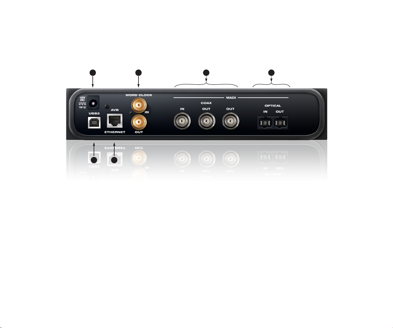
M64 Rear Panel
1 3
6
1. This jack accepts any standard 12-18V DC power
supply (1.0A max) with tip-positive polarity.
2. BNC word clock jacks. Use them for a variety of
applications, such as digital transfers with devices
that cannot slave to the clock supplied by their
digital I/O connection with the M64.
3. These coaxial BNC jacks provide 64 channels of
standard MADI digital input and output at 44.1 or
48 kHz, 32 channels at 88.2 or 96 kHz and 16
channels at 176.4 or 192 kHz. The legacy varispeed MADI format is also supported, which
provides 56, 28 and 14 channels, respectively. The
two outputs are hard wired to mirror each other, so
they cannot operate independently from each
other.
4. These optical MADI IN and OUT jacks provide the
same MADI functionality as the coaxial banks,
except in standard optical format. They operate
completely independently of the coaxial banks,
although if you wish, you can make the coaxial and
optical output banks mirror each other using the
M64’s routing features.
5
5. This AVB/TSN Ethernet port provides industry
standard IEEE 802.1 network connectivity to other
network devices. Examples include:
■
Another M64 or any other MOTU AVB-equipped
audio interface, such as the 1248, 8M, 16A, 24Ai,
24Ao, 112D, Monitor 8, 624, 8A, 8D, LP32, etc.
■
A standard Ethernet hub or Wi-Fi router (for
internet connection and communication with
the web app software).
■
A standard AVB/TSN Ethernet switch for highspeed, low-latency, high-capacity audio connectivity to an AVB/TSN audio network.
■
A recent-generation Mac (any Mac with a
Thunderbolt port) running OS X El Capitan
(10.11) or later. This allows you to operate the
M64 as an audio interface over Ethernet.
42
6. Connect the M64 to the computer here with a
standard USB cable (included). For details, see
chapter 4, “Hardware Installation” (page 33).

MOTU Pro Audio Control Web App
CHAPTER
OVERVIEW
MOTU Pro Audio Control
you complete control over the M64. If you have
several MOTU AVB interfaces networked together,
such as the M64, 1248 and 8M, you can control
them all. If you are working with a large network of
many MOTU AVB interfaces, you can access any
device on the network.
is a web app that gives
IT’S NOT ON YOUR HARD DRIVE
The MOTU Pro Audio Control web app is served
from the M64 hardware itself, therefore it is not an
applicat ion on your computer’s hard drive. Inst ead,
access it from the
menu bar or Windows taskbar), the
Audio WebUI Setup
through your web browser.
MOTU Discovery
shortcut (Windows only) or
app (in the Mac
MOTU Pro
USE YOUR FAVORITE WEB BROWSER
The MOTU Pro Audio Control web app runs in any
modern web browser on any device connected to
the M64, either directly or wirelessly through a
Wi-Fi network. You can use any device you wish: a
desktop computer, laptop, iPad, tablet, i Phone or
smart phone. If it can run a web browser, it can run
the web app. You can use any browser you prefer:
Chrome, Firefox, Safari, etc. The latest versions are
strongly recommended.
CONTROL FROM MULTIPLE DEVICES
You can run the web app on multiple host devices
simultaneously.
RUN THE INSTALLER, GET THE APP
Visit www.motu.com/avb to get the latest MOTU
Pro Audio Installer and run it on your computer to
install the
WebUI Setup
software elements. Visit the Apple App Store to
install the discovery app on your iPad or iPhone.
MOTU Discovery
shortcut (Windows only) and other
app,
MOTU Pro Audio
MAKE HARDWARE AND NETWORK CONNECTIONS
Connect your M64 to your computer or laptop
with a USB cable. Make sure your iPad, iPhone,
tablet or smartphone is connected to the same WiFi networ k as your compute r or de vice. You can use
any network connection explained in “Setup for
web app control” on page 37.
LAUNCHING THE WEB APP
To launch the web app, do any of the following:
■
Choose the M64 from the MOTU Discovery app
menu (in the Mac menu bar or Windows taskbar,
as shown on page 7) or launch the
Audio WebUI Setup
■
From your iPad or iPhone, launch the MOTU
Discovery app.
■
In your favorite web browser, type this URL:
localhost:1280.
connection to the M64.)
■
If the M64 Ethernet port is connected to your
Ethernet or Wi-Fi network, type the unit’s IP
address (see below) into your browser.
You should now see the MOTU Pro Audio Control
web app in your browser, as shown on page 12. If
not visit Appendix A, “Troubleshooting” (page 95).
Obtaining the M64’s IP address
On the front panel of the interface, push the ID
button once. The LCD now displays the unit’s IP
address, which should look something like this:
“IP: 192.168.1.209”.
shortcut (Windows only).
(This URL requires a USB
MOTU Pro
11
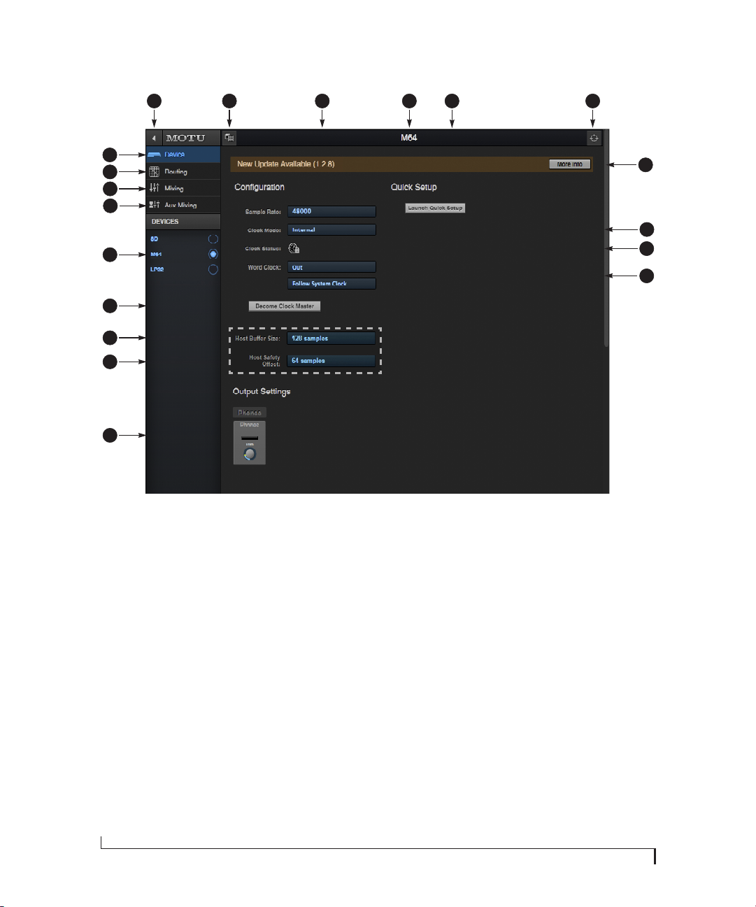
DEVICE TAB
8
96 7 11
10
5
4
3
2
1
19
18
17
16
1. If you have two or more MOTU interfaces, the Devices list lets you choose
the one you are currently controlling
with the web app.
2. The Aux Mixing tab lets you view
each Aux bus in the mixer, one at a
time.
3. The Mixing tab gives you access to
the mixing and DSP in the interface.
4. The Routing tab displays a grid
matrix, where you can make direct
connections between inputs and
outputs, your computer, the mixer,
and network audio streams, if
networked interfaces are connected.
5. The Device tab has settings for the
hardware itself, such as input and
output trim.
6. Expands and collapses the sidebar.
7. Lets you create, save, recall and
manage presets for the M64. These
presets capture and recall the
complete state of the device (all
settings in all tabs).
8. Choose the desired sample rate.
Make sure your host audio software
is set to the same rate.
9. Click to rename the interface. To
restore the default name, delete the
current name.
10. The Quick Setup button prompts
factory presets used to configure
your interface for a specific application. See chapter 5, “Presets”
(page 49).
11. Click this device ID button to identify
the unit you are currently viewing
and controlling with the web app
software. The front panel LCD on the
hardware itself will flash the name
of the device, and its name will also
flash in the Device list (1).
Windows only
12. If an update is available for your
device, and the computer you are
viewing it from is connected to the
internet, you’ll be notified here. Click
More Info to learn what’s new and
start the update process. Firmware
updating requires a network
connection. See Appendix D,
“Updating Firmware” (page 103).
13. Choose the clock source from the
Clock Mode menu. Your MOTU device
will resolve its digital clock to this
master source.
14. The Clock Status icon indicates that
the current device (1) is successfully
resolved to its chosen Clock Mode
source (13). If it cannot lock for some
reason, this icon flashes red. Check
your chosen clock source, cables, etc.
15. The Word Clock output can operate
as an OUT or a THRU. In addition, at
higher sample rates, it can either
follow the system clock or operate at
12
13
14
15
the corresponding 1x sample rate.
For details, see “Daisy-chaining
word clock” on page 43.
16. The Output Settings section lets you
adjust the trim for the headphone
output.
17. ( Windows only) Choose a Host
Safety Offset to fine tune host buffer
latency. See “Host Safety Offset” on
page 31.
18. ( Windows only) Choose the Host
Buffer Size. Smaller values reduce
latency but increase your computer’s
CPU load. See “Host Buffer Size” on
page 30.
19. If you have multiple MOTU interfaces, one of them may serve as a
master clock source for the network.
Click the Become Clock Master button
to choose the current interface (1) as
the master clock source.-
12
MOTU PRO AUDIO CONTROL WEB APP
DEVICE TAB (CONTINUED)
20
21
22
24
23
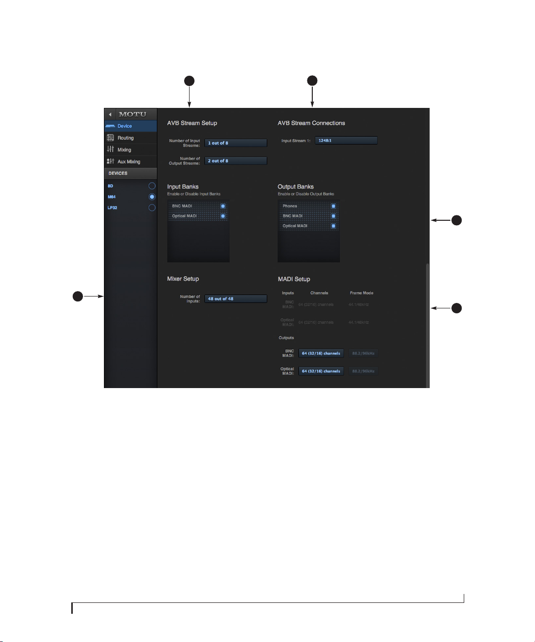
Scroll down to view these additional
Device tab settings.
20. AV B is IEEE’s Audio Video Bridging
Ethernet standard for highbandwidth, low-latency audio
streaming over Ethernet. If your
MOTU interface is connected to a
2nd MOTU interface through its
network port, or to an AVB switch for
access to an extended AVB network,
you can stream audio channels to
and from other devices on the
network. AVB streams are handled
in banks of eight channels, so if you
enable 2 streams, that’s 16 channels.
See chapter 10, “Networking”
(page 87).
MOTU PRO AUDIO CONTROL WEB APP
21. If you have the AVB network input
stream enabled (20), connect them
to the output streams of other
devices on the network here. This is
how you route audio from the other
devices to the M64.
22. In the Input/Output Banks sec tions,
you can disable any banks that you
are not using. Doing so hides them
from the routing matrix and mixer to
simplify operation. Doing so also
helps conserve DSP resources.
23. In the MADI Setup section, the Input
settings are display only, as the
M64’s MADI inputs auto-detect the
incoming format and frame mode.
The Output settings let you choose
between the two standard MADI
formats: legacy 56 channel mode
(which drops to 28 or 14 channels at
higher sample rates) or 64/32/16
mode. At 2x sample rates, you can
choose the desired Frame Mode
(44.1/48 kHz or 88.2/96 kHz).
24. The digital mixer in the M64
supports up to 48 channels at 44.1
or 48 kHz. At higher sample rates,
the maximum number of supported
channels is lower, due to finite DSP
resources: 32 channels at 88.2 or 96
kHz and 16 channels at 176.4 or 192
kHz. If you don’t need 48 inputs (or
the maximum available), you can
lower the number here to simplify
mixer and routing operation and
conserve DSP bandwidth for effects
processing.
13
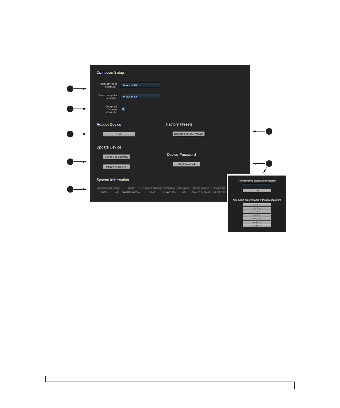
DEVICE TAB (CONTINUED)
25
26
27
28
29
Scroll down to view these additional
Device tab settings.
25. In the Computer Setup section, you
can specify how many audio
channels you would like to be able to
stream to and from your computer,
up to 64 channels each way, simultaneously, over USB. Map them as
desired in the Routing tab
(page 15).
26. When the Computer Volume Controls
option is enabled (a Mac only
feature), the Audio MIDI Setup
utility in OS X provides volume
control for each output channel to
your MOTU audio interface. In
addition, the volume controls for
your Mac (on your computer
keyboard) will control the channels
you’ve designated for computer
output in Audio MIDI Setup, if any.
Be careful when toggling this
setting because sudden changes in
your computer volume can result.
27. Click Reboot to restart the interface.
28. Use these buttons to manually check
for and install updates for your
MOTU interface. For complete
details, see Appendix D, “Updating
Firmware” (page 103). Updating
from a file can be done offline from
your computer, using an update
you’ve obtained through MOTU’s
web site or tech support department. The Check For Updates button
requires that the computer (or
device) you are using to view your
MOTU interface is connected to the
internet through a local network or
Wi-Fi. Updating from the internet is
easy and convenient.
29. The System Information section
displays information about your
MOTU device, including the
firmware version and network IP
address.
30. Use Restore Factory Presets to restore
your MOTU device’s fac tory presets.
31. Use Set Password to password-
protect the interface on the
network. All settings are blocked,
except for aux bus mixing, as shown
above (31). This allows musicians to
access their personal monitor (aux)
mixes from their mobile devices,
while all other device settings
remain blocked. To clear the
password, log in and then click Clear
Password. If you forget the
password, you can clear it in the
Settings menu in the front panel LCD
(see page 54) with either the Clear
Password setting or by doing a
factory reset with the Facto ry
Default setting.
30
31
14
MOTU PRO AUDIO CONTROL WEB APP

ROUTING TAB
5
3
2
1
21
20
19
18
17
The Routing Tab lets you route inputs to
outputs. Outputs are listed by row on the
left; inputs are listed in columns across
the top. Simply click in the grid to make
a single connection. Click and drag to
make multiple connections in one
gesture. To route a single input to multiple outputs, make multiple connections
vertically in the same column below the
input. To mix multiple inputs to the
same output, you’ll need to use the
mixer (page 16) and the Mix In bank in
the routing tab (17).
1. In its collapsed form, (shown here),
the sidebar displays icons for each
tab.
2. Click this icon to view the Routing
tab, shown on this page.
3. Click here to show or hide the
sidebar.
4. Create, save, recall and manage
routing presets.
5. Locks the grid to prevent accidental
changes. Unlock to make changes to
the grid.
64 8
7
6. Outputs are listed in rows on the left.
7. When you make a connection, the
source (input) signal is listed by
name here in the Source column,
just to the right of the output it is
being routed to.
8. Inputs are listed in columns across
the top of the grid, starting with the
physical inputs on the hardware
itself. In this example, the optical
MADI input bank (all 64 channels,
currently collapsed) is being routed
directly to the coaxial (BNC) output
bank to convert all 64 channels from
optical input to coaxial output.
Optical channels 1-2 are also routed
to the headphone L-R output.
9. The From Computer input bank lets
you route audio channels from your
host audio software to any output,
including AVB network streams or
the mixer, where you can mix
computer audio with local inputs.
Use the Device tab to specify the
number of computer channels available (up to 64 channels at 44.1 or 48
kHz).
9 10
10. AVB streams are 8-channel banks
that let you route audio to or from
other devices on the AVB network (if
any are connected) to local
hardware inputs and outputs. Use
the Device tab (page 13) to configure how many AVB streams you wish
to work with. If you aren’t working
with network audio, you can set the
number of streams to zero.
11. These input streams are busses that
originate from the mixer, which
supplies the main mix bus, monitor
mix bus, seven stereo aux busses,
three stereo group busses, a reverb
return bus and postFX channel sends
(for sending processed inputs to the
computer or elsewhere). You can
route these mixer busses to any
outputs you wish (6), including
physical outputs, host software on
your computer, other devices on the
AVB network, or even back in to the
mixer (beware of feedback loops!)
12. Use the triangles in each section to
expand or collapse groups of inputs.
For example, it might be convenient
to collapse banks that you are not
using at the moment.
11
13. Click a channel label to rename it.
14. Audio activit y indicators.
15. Here, the Monitor bus from the
mixer is being routed to optical
MADI output channels 1-2 (currently
collapsed to one row in the grid).
16. Click the grid to make a connection.
Click a connection to remove it. Click
and drag to make or break multiple
connections in one gesture.
17. The Mix In group lets you route audio
to the 48-channel mixer.
18. AVB output streams let you route
any audio to other devices on the
AVB net work .
19. The To Computer output bank routes
any input to host audio software
running on your computer. Use the
Device tab to choose how many
computer channels are available.
20. Use these triangles to expand or
collapse groups of outputs.
21. These are the physical outputs on
the interface itself.
12
13
14
15
16
MOTU PRO AUDIO CONTROL WEB APP
15
MIXING TAB
4 5
6
7
93 13 14
8 10 11 12
15
16
2
1
32
31
30
29
28
27
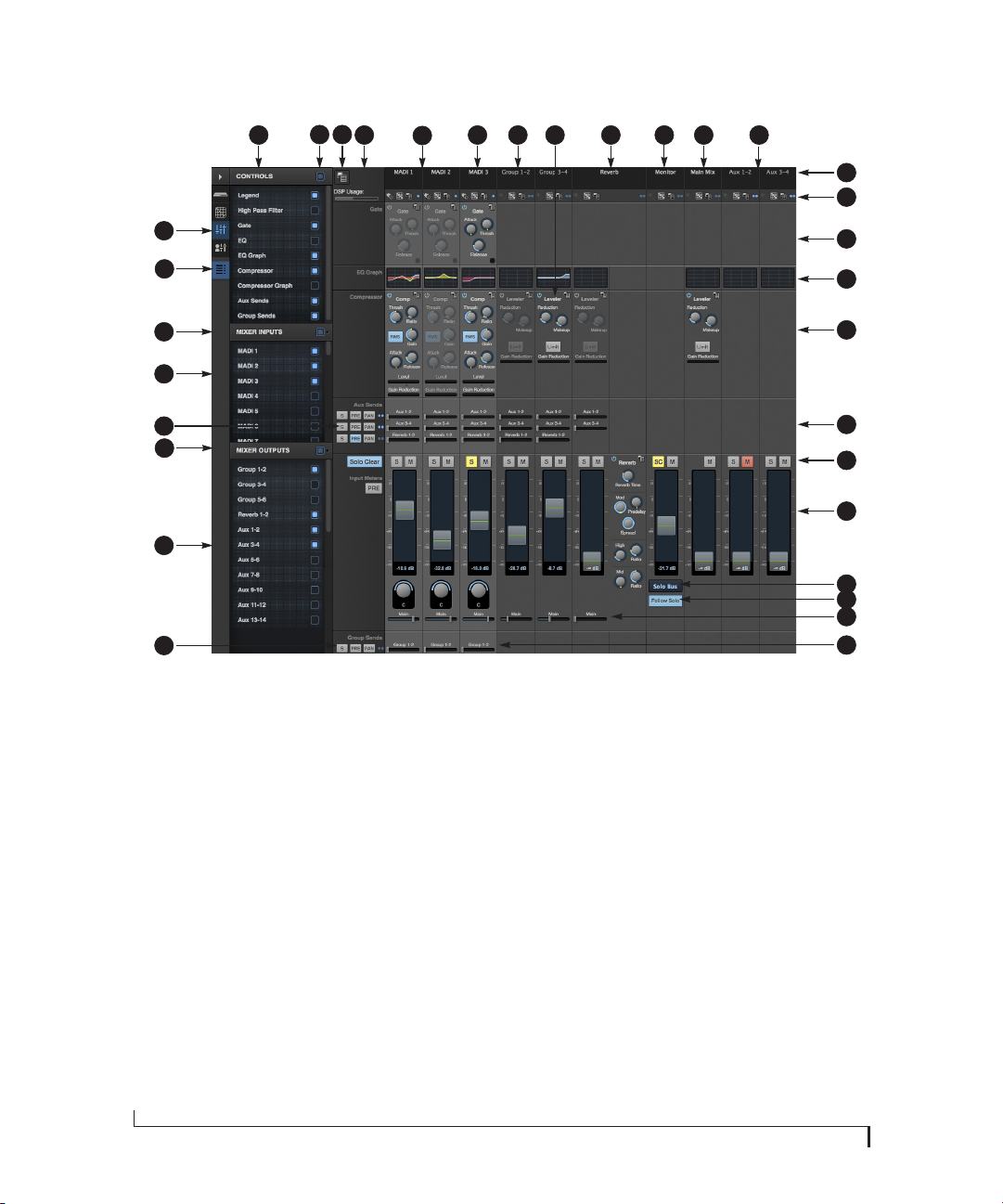
The Mixing tab gives you full access to
the 48-channel mixer in the M64, which
provides a main mix bus, monitor bus,
three group busses, seven aux busses,
and a dedicated reverb bus. Use the
Device tab to configure how many
inputs you wish to work with (up to 48
channels at 1x sample rates, 32 at 2x
rates or 16 at 4x). Use the Routing tab
(page 15) to route channels to the mixer
inputs. Channels can come from any
source, such as the physical inputs on
the interface, the computer, or the AVB
network.
1. Shows and hides the Mixer Setup
sidebar (3), which lets you show and
hide channels and mixer elements.
2. The Mixing tab selects the mixer.
3. Use the Mixer Setup sidebar to show
and hide elements in the mixer.
4. Shows and hides all elements in the
section with one click.
5. Create, save, recall and manage
mixer presets.
6. This column is the Legend. It
provides labels and controls for
16
channel strip sections. The menu at
the top lets you create, name, save
and manage entire mixer presets.
7. Mixer input channels.
8. This input channel has its Gate and
Compressor enabled.
9. This is Group bus 1-2. You can send
inputs to this group with their Group
send fader (26). Groups are sent to
the Main Mix with its Main send
fader (25) or aux busses (20).
10. Group buses, the main mix bus, and
the reverb return bus are equipped
with the Leveler, a vintage compressor modeled after the Teletronix
LA-2A leveling amplifier.
11. The reverb channel strip provides
the reverb processor. Use the reverb
send on inputs or groups to route
them to the reverb bus, which can
then be mixed in with the main mix
or aux busses. Disable the reverb
processor to use it as an extra group.
12. The Monitor Bus can mirror the
output of any other bus, or it can act
as a separate Solo bus. See page 19.
13. The Main Mix bus is the master fader
for the entire mixer. You can add EQ
and Leveler compression.
14. You can adjust Aux bus output levels
here, or in the Aux Mixing tab shown
on page 17.
15. Click a name to change it, except for
the Main Mix, Monitor, and Reverb
busses, which cannot be changed.
16. Stereo toggle to switch channels
pairs between mono or stereo. Use
the other menus to manage channel
strip presets and to choose audio
sources and destinations for mixer
inputs and bus outputs.
17. Gate processing for inputs.
18. Click the thumbnail EQ graph to
open the full-size, editable EQ graph
(Figure 8-4 on page 65).
19. The Dynamics sec tion provides a
conventional compressor for inputs
and the Leveler for output busses.
20. Reverb and aux sends.
MOTU PRO AUDIO CONTROL WEB APP
21. Solo and mute. On the Monitor bus,
the SC button clears all solos.
22. Channel faders.
23. Choose the source for the Monitor
bus from this menu. It can mirror
any output bus or the Solo Bus.
24. When Follow Solo is enabled, the
Monitor bus temporarily switches to
the solo bus when any channel is
soloed.
25. Main Mix sends.
26. Group sends.
27. ‘S’ lets you solo the group. ‘PRE’
toggles the sends between pre- and
post-fader routing, i.e. before or
after the channel fader.
28. Show and hide output busses here.
29. Show/hide all busses with one click.
30. S ame as (27) above.
31. Show and hide inputs here.
32. Show/hide all inputs with one click.
17
18
19
20
21
22
23
24
25
26
AUX MIXING TAB
2
1
4
53
6
8
7
9
10
17
16
15
14
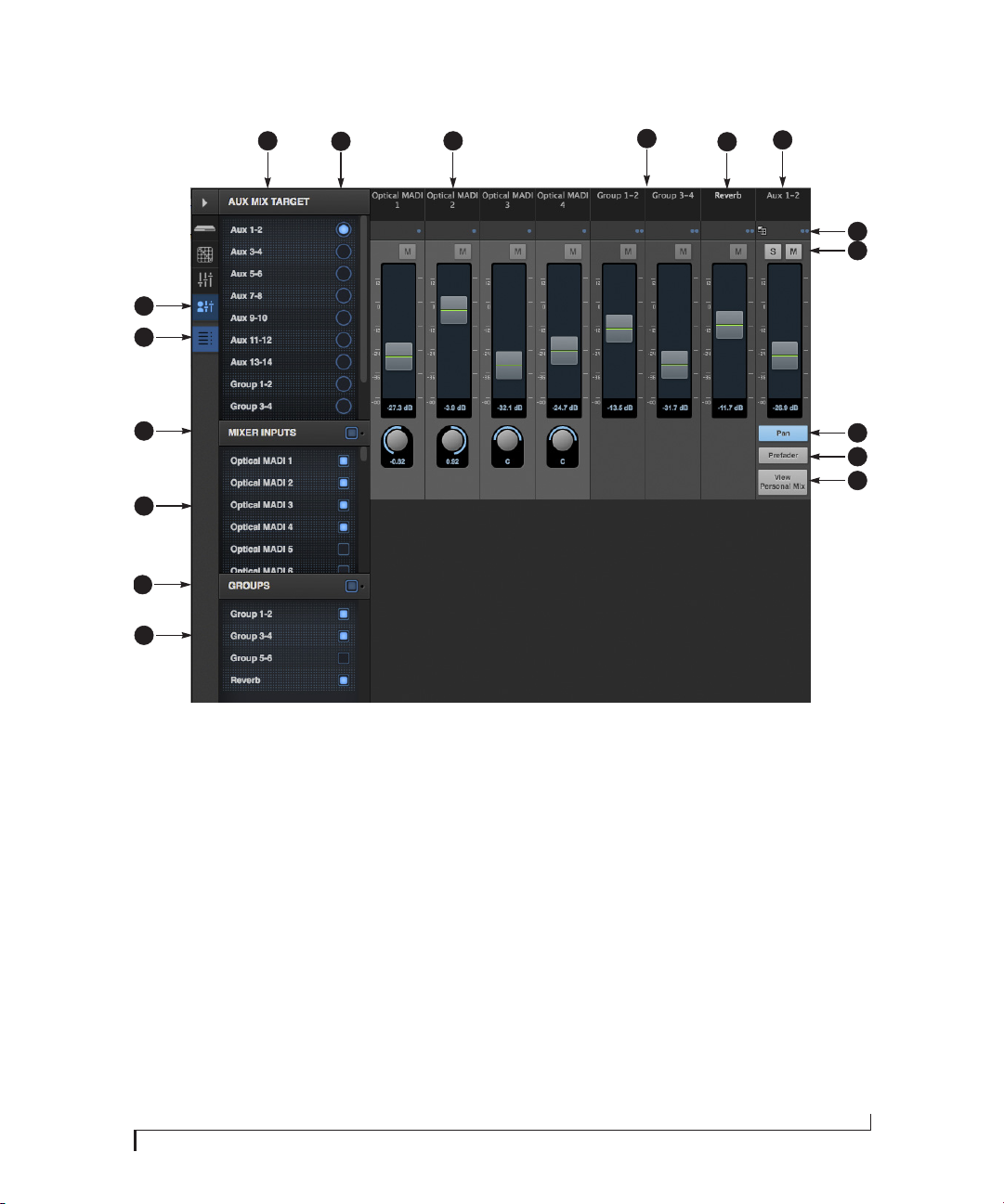
The Aux Mixing tab provides quick
access to the M64’s mix busses (aux
busses, groups and reverb bus), viewed
one at a time. Choose a bus in the Aux
Mix Target section and then use the
faders to directly mix the send levels
from all mixer inputs, groups, and the
reverb bus.
1. Shows and hides the Mixer Setup
sidebar (3), which lets you show and
hide channels.
2. The Aux Mixing tab (shown on this
page) gives you access to the Aux
busses and groups in the mixer.
3. Use the Aux Mix Target sidebar to
control which aux bus or group you
are currently viewing. You can also
show/hide inputs and group sends.
4. Click the aux bus or group you wish
to view in the window. In this
example, Aux bus 1-2 is being
displayed.
5. These are mixer inputs (aux sends
from each mixer channel). To include
an input in the aux bus mix, simply
bring up its fader.
6. These are group bus faders.
7. This is the mixer’s reverb bus fader.
8. This is the master fader for the
current aux bus being viewed (4).
9. Indicates if the input or group is
stereo or mono. This indicator is for
display purposes only. To toggle
between mono and stereo operation, use the toggle switch in the
Mixing tab (item #16 on page 16).
10. Solo and mute for the aux bus
master fader. The mute buttons for
the input channels and other buses
are for display purposes only, so that
you can see if they are muted or not
(in the mixer).
11. Shows and hides the pan controls for
aux bus inputs.
12. When Prefader is enabled, all send
levels to the aux bus are independent of the main fader for each
channel. In other words, changing
an individual channel’s main fader in
the Mixing tab won’t affect its send
level to the aux bus.
13. Click the View Personal Mix button to
open a new web page that displays
only that specific Aux Mix or Group.
11
12
13
14. Show and hide mix groups and the
reverb bus here.
15. Use the Groups button here to show
or hide all groups with one click.
Drag this section divider vertically to
resize the list.
16. Show and hide mixer inputs
(channel sends) here.
17. Show and hide all mixer inputs with
one click here. Drag this section
divider vertically to resize the list.
MOTU PRO AUDIO CONTROL WEB APP
17

MIXER INPUT CHANNEL STRIPS
1
30
29
28
27
26
25
18
6
7
2
8
9
3
10
11
12
4
13
14
15
12
16
17
18
19
20
21
22
23
24
2 3 4 5
To access a mixer input channel strip, go to
the Mixing tab (page 16), reveal the side bar
(item #3 on page 16), and then show the
input channel you want in the Mixer Inputs
section (31).
To show and hide sections of the channel
strip, such as EQ or the compressor, use the
Contro ls section of the side bar (item #3 in the
Mixing tab on page 16).
1. Click the input channel name to change
it. Delete the current name to restore the
default name.
2. Provides hardware settings for inputs, if
any, such as preamp gain. If there are no
hardware settings for the assigned input,
this icon is grayed out. If the channel has
been assigned to an input on another
AVB device on the audio network, you can
use these settings to control it remotely.
3. Choose the source for the input channel.
You can also make this setting directly on
the Routing grid (page 15).
4. Create, name, save and recall channel
strip presets.
5. Toggles the input between mono and a
stereo pair.
6. High Pass Filter with cutoff frequency.
7. Each effect in the channel strip (High Pass
Filter, Gate, EQ, etc.) has an on/off button
on the left and a preset menu on the
right, for managing presets that apply
only to that processing module. For
example, you can create your own EQ
presets for the EQ modules.
8. The Gate processor provides standard
attack, threshold and release controls.
9. The Gate indicator turns red when the
gate is engaged.
10. The EQ section provides four bands of
parametric EQ, each with standard Gain,
Frequency, and Bandwidth settings.
11. The High and Low EQ bands provide a
Shelf filter button for standard high and
low shelf filtering.
12. The thumbnail EQ Graph displays the
currently enabled EQ filters, if any. Click it
to open the full-size, editable EQ Graph
(Figure 8-4 on page 65).
13. The Compressor provides standard
controls for Threshold, Ratio, Attack,
Release and Gain. Normally, the compressor operates in Peak mode, where signal
peaks determine the input level. Engage
the RMS button to uses RMS values (a
computational method for determining
overall loudness) to measure the input
level.
MOTU PRO AUDIO CONTROL WEB APP
14. Input level and gain reduction meters for
the compressor.
15. The thumbnail Compressor Graph
provides a graphic representation of the
compressor, when enabled. Click it to
open the full-size, editable Compressor
Graph (Figure 8-6 on page 66).
16. Aux 1-2 send.
17. Pan for the Aux 1-2 send. This is enabled
with the Pan button (item #28).
18. Solo/Mute. Mute affects all sends as well
as the main channel. Pre-fader sends are
not affected by Mute.
19. Move the fader to adjust level. Doubleclick to return to zero (unity gain) or -∞.
20. Click the dB scale numbers to make the
fader jump exactly to that level. Click and
drag horizontally to jump consecutive
faders to the same level.
21. Click to type in an exact dB level.
22. Channel pan. For mono inputs, doubleclick to center.
23. Main Mix Slider is used to feed signal to
the Main Mix. Slider is set to 0 dB by
default, so all channel strips are prerouted to the Main Mix bus. If a channel is
being sent to a Group (which will eventually be fed to the Main Mix), drag the
slider to -∞ so it is not sent to Main Mix
directly.
24. Group sends.
25. ‘S’ lets you solo the group. ‘PRE’ toggles
the sends between pre- and post-fader
routing, i.e. before or after the channel
fader.
26. The input level meter (behind the fader
handle, 19) can display either pre- or
post-fader levels. Toggle here.
27. Clears all solos.
28. ‘S’ lets you solo the Aux bus. ‘PRE’ toggles
the sends between pre- and post-fader
routing, i.e. before or after the channel
fader. The dots let you toggle the Aux bus
between mono and stereo.
29. This side bar, with the section labels in it,
can be shown or hidden using the Legend
switch in the Contro ls section of the side
bar (item #3 in the Mixing tab on
page 16).
30. Shows how much DSP power is being
used by the mixer hardware. To free up
DSP bandwidth, try reducing the number
of mixer ins, disabling channel effects,
reverb, etc. See “DSP Usage” on page 69
for more info.
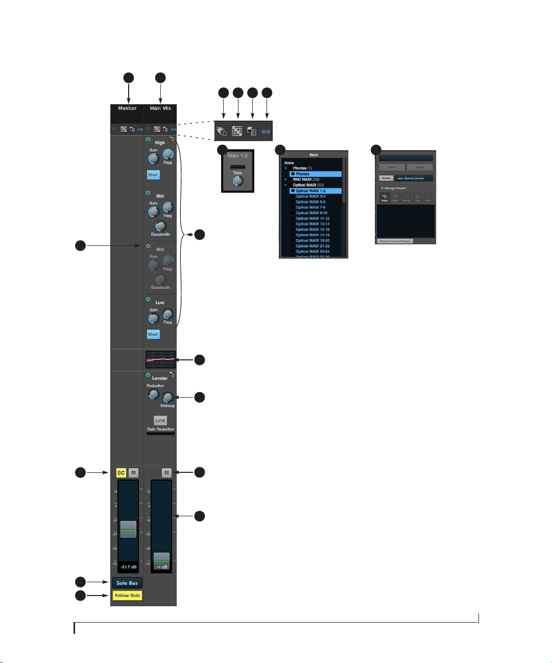
MAIN MIX AND MONITOR CHANNEL STRIPS
1
2
3 4 5 6
3 4
5
7
15
To access the Main Mix and Monitor bus
channel strips, go to the Mixing tab
(page 16) and scroll the display to the
right, beyond the inputs and groups.
To show and hide sections of the channel
strip, such as EQ or the Leveler, use the
Contro ls section of the side bar (item #3 in
the Mixing tab on page 16).
1. By default, the Monitor bus serves as
8
9
14
10
11
13
12
a solo bus. However, it can be set to
mirror the main mix bus, or any other
aux bus, group, or the reverb bus, in
addition to monitoring solo. Make
this choice in the source menu (13).
Use the Routing grid (page 15) to
specify the output for the Monitor
bus.
2. The Main Mix bus is the primary
stereo mix.
3. Provides hardware settings for any
assigned outputs that have them. For
example, if the Main Mix bus is
assigned to outputs 1-2 on the M64,
you’ll see trim settings for the
outputs. This item is grayed out if
there are no hardware settings for
output.
4. Use this output assignment widget to
choose the destination — or multiple destinations — for the bus. You
can also make this setting directly on
the Routing grid (page 15).
5. Use the preset menus to create save,
recall, and otherwise manage
channel strip presets for the Monitor
bus and Main Mix bus.
6. Indicates that the bus is stereo.
7. The four-band parametric EQ for the
Main Mix bus operates the same as
described for input channels (items
10 and 11 on page 18), including
High and Low Shelf filter options.
8. The thumbnail EQ Graph displays the
currently enabled EQ filters, if any.
Click it to open the full-size, editable
EQ Graph (Figure 8-4 on page 65).
9. The Leveler provides specialized gain
reduction modeled after the legendary Teletronix LA-2A Leveling Amplifier. For complete details, see
“Leveler” on page 67.
10. Mutes for the Main Mix bus and
Monitor bus.
11. Master faders for the Main Mix bus
and Monitor bus. Use the same
techniques described for input
channel faders (items 19, 20 and 21
on page 18).
12. When Follow Solo is enabled, the
Monitor bus switches to the solo bus
when any channel is soloed. NOTE: if
an aux bus is soloed, then the Monitor
bus carries only the soloed aux bus
(any current channel solos are
excluded).
13. Choose the source for the Monitor bus
from this menu. It can mirror the
main mix, any aux bus, group, the
reverb bus, or it can serve only as a
Solo bus.
14. The SC button clears all solos.
15. This mid-band EQ is currently
disabled (and therefore grayed out).
MOTU PRO AUDIO CONTROL WEB APP
19
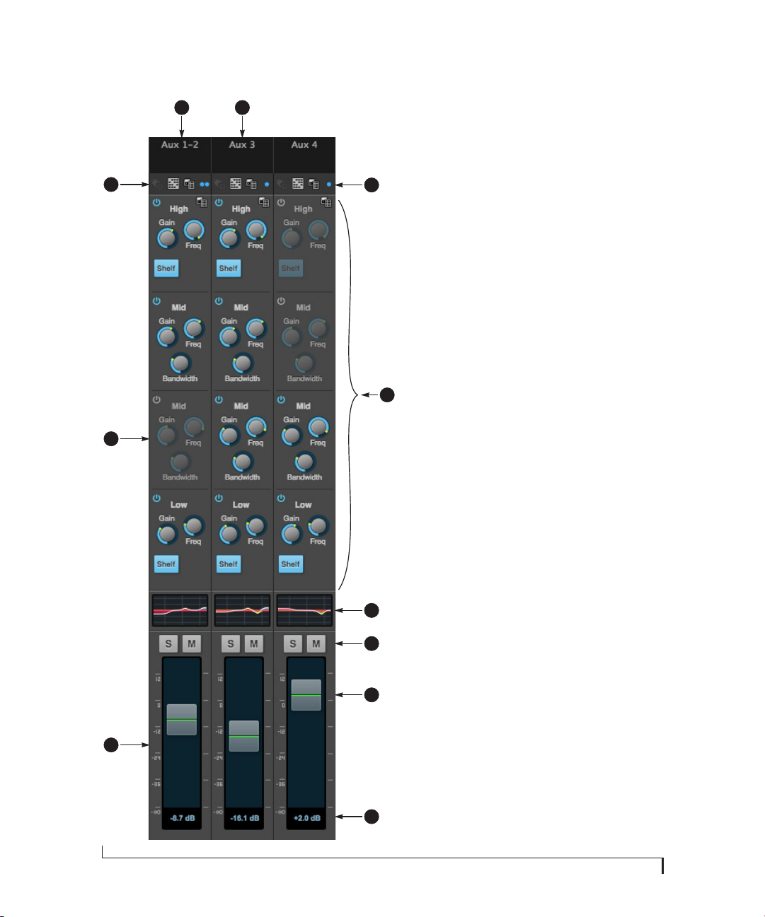
AUX BUS CHANNEL STRIPS
20
1
11
10
9
2
3
Aux busses can be used to create sub-mixes.
An aux bus can be assigned to any output in
the Routing grid (page 15).
To access an Aux bus channel strip, go to the
Mixing tab (page 16), reveal the side bar (item
4
5
6
7
8
#3 on page 16), and then show the aux busses
you want in the Mixer Outputs section (28).
To show and hide the four-band EQ section of
the channel strip, use the Cont rols section of
the side bar (item #3 in the Mixing tab on
page 16).
1. A stereo aux bus.
2. A mono aux bus.
3. Click this dot to toggle an aux bus between
mono and stereo.
4. The four-band parametric EQ module for
Aux busses operates the same as described
for input channels (items 10 and 11 on
page 18), including High and Low Shelf
filter options.
5. The thumbnail EQ Graph displays the
currently enabled EQ filters, if any. Click it
to open the full-size, editable EQ Graph
(Figure 8-4 on page 65).
6. Aux bus solo and mute.
7. Aux bus master fader.
8. Click to type specific value manually.
9. Click the dB scale numbers to make the
fader jump exactly to that level. Click and
drag horizontally to jump consecutive
faders to the same level.
10. A disabled EQ band.
11. Use these menus (hardware settings,
output assignment, and presets) in a
similar fashion as described for the Main
Out bus (items 3-5 on page 19).
MOTU PRO AUDIO CONTROL WEB APP
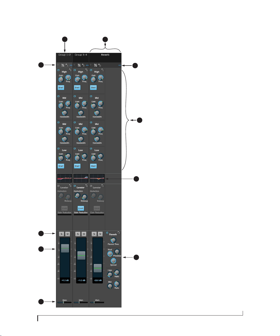
GROUP AND REVERB CHANNEL STRIPS
1
2
10
9
8
3
Group busses can be used to create a mix subgroup, which is a set of inputs you wish to control
together as a group. Groups differ from aux busses
in that they have aux sends, a reverb send, as well
as a main mix send. In addition, group busses are
equipped with the Leveler.
The Reverb bus is a special group bus that provides
a reverb processor. If you disable the reverb, the
reverb bus functions as a (fourth) regular group
bus.
4
5
6
To access the Group and Reverb bus channel strips,
go to the Mixing tab (page 16), reveal the side bar
(item #3 on page 16), and then show the desired
Group busses or Reverb bus in the Mixer Outputs
section (28).
To show and hide the four-band EQ section of the
channel strip, use the Cont rols section of the side
bar (item #3 in the Mixing tab on page 16).
1. A Group bus channel strip. Click the name to
rename it. Delete the current name to return to
its default.
2. The Reverb bus. If you disable the Reverb
processor, it can be used as a fourth Group bus.
The Reverb channel strip is twice as wide as
other mixer channel strips to accommodate the
Reverb processor controls.
3. Group busses and the Reverb bus are always
stereo.
4. The four-band parametric EQ module for Group
busses and the Reverb bus operates the same
as described for input channels (items 10 and
11 on page 18), including High and Low Shelf
filter options.
5. The thumbnail EQ Graph displays the currently
enabled EQ filters, if any. Click it to open the
full-size, editable EQ Graph (Figure 8-4 on
page 65).
6. The Reverb processor. For complete information, see “Reverb” on page 68.
7. Main Mix sends.
8. Master faders for the Group and Reverb busses.
9. Mute and Solo.
10. Use these menus (hardware settings, output
assignment, and presets) in a similar fashion as
described for the Main Out bus (items 3-5 on
page 19).
7
MOTU PRO AUDIO CONTROL WEB APP
21

22
MOTU PRO AUDIO CONTROL WEB APP

CHAPTER
1
About the M64
The M64 is a flexible MADI interface, router,
repeater, splitter, converter and stand-alone mixer
with AVB/TSN networking and connectivity to a
host computer through class compliant, highspeed USB 2.0 (compatible with USB 3.0 and iOS).
The M64 provides 64 channels each of optical
MADI I/O, BNC (coaxial) MADI I/O, USB and
AVB-TSN network I/O, plus a headphone output,
for 514 simultaneous I/O channels. A convenient,
assignable front-panel headphone output with
volume control allows for convenient monitoring
of any stereo channel pair.
Powerful DSP delivers large console style mixing
with 48 channels, 12 stereo busses, and 32-bit
floating point effects processing, including
modeled analog EQ, vintage compression and
classic reverb. Matrix routing lets you quickly
patch ins to outs, or split inputs to multiple
destinations.
Housed in a sturdy aluminum alloy half-rack
enclosure, the M64 is ideal for routing 64-channel
MADI streams in live performance systems, AVB/
TSN network installations or recording studios of
any size.
The following sections provide a brief overview of
its main features and characteristics.
Comprehensive I/O
All M64 I/O channels are independent and active
simultaneously.
Connection Input Output
Optical MADI 64 64
BNC MADI 64 64
USB 64 64
AVB-TSN Ethernet 64 64
Headphone output - 1 (stereo)
Total 256 258
MADI
The M64 provides full support for MADI digital
input and output, in all standard formats and
sample rates from 44.1 to 192 kHz. A duplicate
BNC output is included for mirroring the coax
bank to a second destination, without the need for
a separate splitter.
Network I/O
The M64 is capable of handling eight 8-channel
banks of network audio input and eight 8-channel
banks of network output for a total of 64 channels
of network I/O.
Other MOTU AVB interfaces
The M64 is part of a larger family of audio
interfaces that offer complementary I/O configurations. For details, visit motu.com.
Universal computer connectivity
The M64 can connect to a computer with hi-speed
USB 2.0, which is compatible with USB 3.0. It is
USB audio class-compliant, which means that it is
iOS compatible (with a camera connection kit) and
does not require driver installation for USB
connection to a computer.
23

Alternately, the M64 can be connected to the
Ethernet port on a recent-generation Mac (any
Mac with Thunderbolt on it) running Mac OS X El
Capitan (10.11) or later for audio interface
operation through AVB Ethernet.
extended bank of I/Os for your computer-based
production system (or both). You can even connect
multiple computers, each with full access to all
devices on the network (including the other
computers).
On-board DSP with mixing and effects
M64 is equipped with a powerful DSP engine that
drives both an extensive routing matrix and a
48-input digital mixer with 12 stereo busses and
effects. The mixer offers familiar operation
modeled after large format mixing consoles.
32-bit floating point processing
All of the mixing and effects processing in the DSP
engine is handled with 32-bit floating point
calculations, to maintain and deliver virtually
unlimited headroom and the utmost in sound
quality.
Modeled vintage effects processing
Effects include “classic” reverb, compression
modeled after the legendary Teletronix LA-2A
compressor, and 4-band EQ modeled after British
analog console EQs.
AVB/TSN system expansion and audio networking
AV B stands for the IEEE 802.1 Audio Video
Bridging Ethernet standard for high-bandwidth,
low-latency audio streaming over Ethernet. You
may also hear AVB referred to as AV B / T S N or
simply TSN because the IEEE is in the process of
renaming the standard to Time Sensitive
Networking to accommodate the expanding scope
of the specification to applications beyond audio
and video.
The AVB Ethernet network port on the M64 lets
you add a second AVB-equipped MOTU interface
using any standard CAT-5e Ethernet cable. You can
ne twor k up to five M OTU i nter fac es to get her us ing
a MOTU AVB Switch™ (sold separately), and then
run them as a stand-alone network or as an
With additional standard AVB switches (from
MOTU or other brands) and standard Ethernet
cabling, you can build an extensive AVB audio
network. The entire network operates with nearzero network latency, even over very long cable
runs. MOTU’s AVB implementation allows you to
stream hundreds of audio channels among devices
and computers on the network with guaranteed
Quality of Service (QoS), prioritizing audio
streams over less important traffic.
Matrix routing and multing
The M64 provides completely flexible matrix-style
audio routing and multing. You can route any
input, computer channel, or network stream to any
other output, computer, or network device. You
can also mult any single input to unlimited
multiple output destinations.
Web app control
You can control the M64’s on-board DSP, mixing,
device settings, clock/sync settings and network
audio routing from the MOTU Pro Audio Control
web app software running in your favorite browser
on a laptop, tablet or smart phone. Multiple dev ices
can be used simultaneously on a shared Wi-Fi
network to access any audio interface settings.
Optional password protection prevents
unauthorized access from the network.
Stand-alone mixing with wireless control
If you connect the M64 to an Apple Airport or
other Wi-Fi router with a standard Ethernet cable,
you can control its powerful mixing and DSP
effects from your smart phone or tablet, without a
computer — great for live sound mixing from your
iPad, tablet, or other wireless device.
24
ABOUT THE M64

Comprehensive metering
The color LCD displays all signal activity at a
glance with detailed metering for all I/O. You can
access many hardware settings directly from the
front panel.
Headphone output
The M64 front panel provides an independent
headphone jack with separate volume control. You
can program the phones to mirror another set of
outputs or act as its own independent output.
Rack mount or desktop operation
The M64 is housed in a sturdy, metal-alloy halfrack enclosure. Rack mounting brackets are
included for mounting side by side with any other
MOTU half-rack unit.
Audio analysis tools
The included MOTU Audio Tools application for
Mac and Windows provides advanced audio
analysis tools, including a full-screen real-time
FFT display, spectrogram “waterfall” display, fullfeatured oscilloscope, X-Y plot and phase analyzer.
AudioDesk
AudioDesk is a full-featured audio workstation
software package for Mac and Windows that is
available as a free download for you as an M64
owner. Visit motu.com/avb to obtain your copy.
AudioDesk provides multi-channel waveform
editing, automated virtual mixing, graphic editing
of ramp automation, real-time effects plug-ins with
crossfades, support for many third-party audio
plug-ins, sample-accurate editing and placement
of audio, and more.
ABOUT THE M64
25

26
ABOUT THE M64

CHAPTER
2 Packing List and
System Requirements
PACKING LIST
the M64 ships with the items listed below. If any of
these items are not present in the box when you
first open it, please immediately contact your
dealer or MOTU.
■ One audio interface
■ One USB cable
■ One DC power adapter
■ One rack mounting kit with brackets and screws
■ One manual
■ Product registration card
SYSTEM REQUIREMENTS
■ A 1 GHz Intel-based Mac or Pentium-based PC
(or compatible). Faster CPUs are recommended
for best performance.
■ 2 GB RAM; 4 GB or more recommended.
■ OS X 10.8 or later; Windows 7 or later; for
operation as an AVB Ethernet audio interface, Mac
OS X 10.11 or later is required, running on a
recent-generation Mac (any Mac with a
Thunderbolt port on it).
PLEASE REGISTER TODAY!
Please register the M64 today. There are two ways
to register.
■ Visit www.motu.com/register
OR
■ Fill out and mail the included product
registration card
As a registered user, you will be eligible to receive
technical support and announcements about
product enhancements as soon as they become
available. Only registered users receive these
special update notices, so please register today.
Thank you for taking the time to register your new
MOTU products!
■ Available high-speed USB 2.0 (or 3.0) port.
■ A large hard drive (preferably at least 500 GB).
27

28
PACKING LIST AND SYSTEM REQUIREMENTS

CHAPTER
3 Software Installation
OVERVIEW
USB audio class-compliant operation. . . . . . . . . . . . . . . . 29
Software installation. . . . . . . . . . . . . . . . . . . . . . . . . . . . . . . . . 29
Audio drivers . . . . . . . . . . . . . . . . . . . . . . . . . . . . . . . . . . . . . . . . 30
MOTU Discovery app . . . . . . . . . . . . . . . . . . . . . . . . . . . . . . . . 31
MOTU Pro Audio WebUI Setup for Windows . . . . . . . . . 31
MOTU Audio Tools . . . . . . . . . . . . . . . . . . . . . . . . . . . . . . . . . . . 31
AudioDesk workstation software . . . . . . . . . . . . . . . . . . . . 31
Working with host audio software . . . . . . . . . . . . . . . . . . . 31
USB AUDIO CLASS-COMPLIANT OPERATION
The M64 is a USB audio class-compliant device.
This means that you can connect it to your Mac
(running OS X 10.8 or higher) with a USB cable
and use it without installing any software drivers.
The computer recognizes the M64 as a USB audio
device and makes its inputs and outputs available
to your host audio software. Basic settings, such as
the hardware’s sample rate, are made in either your
host software (Mac) or your system settings
(Windows).
☛ In this scenario, the M64 provides basic audio
input and output, and no software driver
installation is necessary.
features. Since the web app is served from the audio
interface hardware itself, it does not require any
software installation on your computer; all it
requires is a network connection between your
computer and the M64 with a standard Ethernet
cable, Ethernet hub, or shared Wi-Fi network. For
details about accessing the web app through the
network port, see “MOTU Pro Audio Control Web
App” on page 11.
SOFTWARE INSTALLATION
Software installation is required for any of the
following scenarios:
■ You are using a PC running Windows 7 or later.
■ You will use M64 as a USB audio interface, and
you want to access the web app without the
network port.
■ You will be using multiple MOTU interfaces.
If none of the above scenarios apply to you, then
you can skip software installation if you wish, and
proceed to details about accessing the web app
through the network port, see “MOTU Pro Audio
Control Web App” on page 11.
Connection to iOS devices (iPad and iPhone)
Audio-class compliant operation allows you to
connect the M64 to any iOS device with a standard
camera connection kit adapter. The M64 then
provides multi-channel audio I/O to your audio
apps. Use your audio app to configure the number
of available audio channels.
Web app control
As explained earlier in this guide, the MOTU Pro
Audio Control web app provides full access to all
settings in the device, including the extensive onboard routing, mixing, and effects processing
Download and run the MOTU Pro Audio Installer
To download the latest MOTU Pro Audio installer
for Mac or Windows, visit www.motu.com/avb.
Follow the directions that the installer gives you.
☛ We recommend that you run the software
installer before you connect the M64 to your
computer and power it on. This ensures that all
driver components are properly installed in your
system.
29
AUDIO DRIVERS
The installer provides USB audio drivers for Mac
(CoreAudio) and Windows (ASIO and Wave).
Industry-leading I/O latency performance
On OS X and Windows, the MOTU Pro Audio
driver provides exceptionally low I/O latency
performance for USB operation. For example, with
a 32-sample buffer size, an M64 interface operating
at 96 kHz produces round trip latency (RTL)
performance of 1.63 milliseconds (ms) over USB
on Windows and 1.61 ms on OS X. RTL is the
measurement of the time it takes audio to pass
from an input, through a high-performance DAW
host such as Digital Performer, to an output.
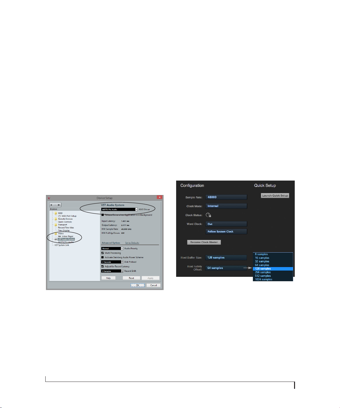
MOTU Pro Audio ASIO Driver
On Windows, to enable the M64 in your ASIO host
software, choose the MOTU Pro Audio ASIO
driver.
WDM / Wave driver support
On Windows, the MOTU Pro Audio driver
includes stereo and multi-channel support (up to
24 channels) for WDM (Wave) compatible audio
software.
Host Buffer Size
When connected to a Windows host, the Host
Buffer Size menu (Figure 3-2) is available in the
Device tab (page 12). This setting determines the
amount of latency (delay) you may hear when live
audio is patched through your Windows audio
software. Smaller buffer sizes produce lower
latency, with sizes of 256 samples or less producing
virtually imperceptible delay. Many host
applications report audio hardware I/O latency, so
you can see what happens to the reported latency
when making adjustments to this setting.
Figure 3-1: Choosing the MOTU Pro Audio ASIO driver in Cubase.
30
Figure 3-2: Access the ‘Host Buffer Size’ and ‘Host Safety Offset’
settings in the web app Device tab for your MOTU interface.
Be careful with very small buffer sizes, as they can
cause performance issues from your host software
or PC.
☛ At sea level, audio travels approximately one
foot (30 cm) per millisecond. A latency of ten
milliseconds is about the same as being ten feet
(three meters) from an audio source.
SOFTWARE INSTALLATION