

Page 1

M2
™™
|
M4
™
|
M6
User Guide
Title Page
1280 Massachusetts Avenue
Cambridge, MA 02138
Business voice: (617) 576-2760
Business fax: (617) 576-3609
Web site: www.motu.com
Tech support: www.motu.com/support
Page 2
SAFETY PRECAUTIONS AND ELECTRICAL REQUIREMENTS FOR THE M2, M4 and M6 (“PRODUCT”)
This equipment has been type tested and found to comply with the limits for a class B digital
device, pursuant to Part 15 of the FCC Rules. These limits are designed to provide reasonable
protection against harmful interference in a residential installation. This equipment generates,
uses, and can radiate radio frequency energy and, if not installed and used in accordance with the
instruction manual, may cause harmful interference to radio communications. However, there is
no guarantee that interference will not occur in a particular installation. If this equipment does
cause interference to radio or television equipment reception, which can be determined by
turning the equip ment off and on, the user is encouraged to try to cor rect the interference by any
combination of the following measures:
• Relocate or reorient the receiving antenna
• Increase the sepa ration between the equip ment and the receiver
• Plug the equipment into an outlet on a circuit different from that to which the receiver is
connected
If necessary, you can consult a dealer or experienced radio/television technician for additional
assistance.
PLEASE NOTE: only equipment certified to comply with Class B (computer input/output devices,
terminals, p rinters, e tc.) should be attached to this equ ipment, an d it must h ave shielded interfac e
cables in order to comply with the Class B FCC limits on RF emissions.
WARNING: changes or modifications to this unit not expressly approved by the
party responsi ble for compliance could voi d the user's authority to oper ate the
equipment.
CAUTION! READ THIS SAFETY GUIDE BEFORE YOU BEGIN INSTALLATION OR OPERATION. FAILURE TO COMPLY WITH SAFETY INSTRUCTIONS
COULD RESULT IN BODILY INJURY OR EQUIPMENT DAMAGE.
HAZARDOUS VOLAGES: CONTACT MAY CAUSE ELECTRIC SHOCK OR BURN. TURN OFF UNIT BEFORE SERVICING.
WARNING: TO REDUCE THE RISK OF FIRE OR ELECTRICAL SHOCK, DO NOT EXPOSE THIS APPLIANCE TO RAIN OR OTHER MOISTURE.
CAUTION: TO REDUCE THE RISK OF ELECTRICAL SHOCK, DO NOT REMOVE COVER. NO USER-SERVICEABLE PARTS INSIDE. REFER SERVICING TO QUALIFIED
SERVICE PERSONNEL.
WARNING: DO NOT PERMIT FINGERS TO TOUCH THE TERMINALS OF PLUGS WHEN INSTALLING OR REMOVING THE PLUG TO OR FROM THE OUTLET.
WARNING: IF NOT PROPERLY GROUNDED THE MOTU PRODUCT COULD CAUSE AN ELECTRICAL SHOCK.
IMPORTANT SAFEGUARDS
1. Read these instructions. All the safety and operating instructio ns should be rea d before operating t he product.
2. Keep these instructions. These safety instructions and the product owner’s manual should be retained for future reference.
3. Heed all warnings. All warnings on the product and in the owner’s manual should be adhered to.
4. Follow all Instructions. All operating and use instructions should be followed.
5. Do not use the product near water.
6. Cleaning - Unplug the product from the computer and clean only with a dry cloth. Do not use liquid or aerosol cleaners.
7. Ventilation - Do not block any ventilation openings. Install in accordance with the manufacturer’s instruc tions.
8. Heat - Do not install the product near any heat sources such as radiators, heat registers, stoves, or another appa ratus (including an amplifier) that produces heat.
9. Overloading - Do not overload wall outlets and extension cords as this ca n result in a risk of fire or electrical s hock.
10. Power cord - Protect the product power cord from be ing walked on or pinched by items placed upon or against them. Pay particular attention to cords and plugs, convenience receptacles, and the point where they exit
from the unit.
11. Power switch - Install the product so that the power switch can be accessed and operated at all times.
12. Disconnect - The main plug is considered to b e the disconnect device for the produc t and shall remain readily operable.
13. Accessories - Only use attachments/a ccessories specified by the manufac turer.
14. Placement - Use only with the cart, stand, tripod, bracket or table specified by the manufacturer, or sold with the product. When a cart is used, use caution when movi ng the cart/apparatus combination to avoid injury
from tip-over.
15. Surge protection - Unplug the product during lightning storms or when unused for long periods of time.
16. Servicing - Refer all ser vicing to qualified serv ice personnel. Servici ng is required when the produc t has been damaged in any way, such as when a power-supply cord or plug is dam aged, liquid has been spille d or objects
have fallen into the product, the product has been exposed to rain or moisture, does not operate normally, or has been dropped.
17. Power Sources - Refer to the manufacturer’s operating instructions for power requirements. Be advised that different operating voltages may require the use of a different line cord and/or attachment plug.
18. Installation - Do not install the product in an u nventilated rack, or directly above heat-producing equipment such as power amplifiers. Observe the maximum ambient operating temperature listed below.
19. Power amplifiers- Never attach audio power amplifier outputs directly to any of the u nit’s connectors.
20. Replacement Parts - When replacement parts are required, be sure the ser vice technician has used replacement par ts specified by the manufacturer or have the same characteristics as the original part. Unauthorized
substitutions may result in fire, electric sho ck or other hazards.
21. Safety Check - Upon completion of any service or repairs to this MOTU product, ask the service technician to perform safety checks to determine that the product is in safe operating conditions.
ENVIRONMENT, HEAT AND VENTILATION
Operating Temperature: 10°C to 40°C (50°F to 104°). The product should be situated away from heat s ources or other equipment that produces heat. When installing the product in a rack or any other location, be sure there
is adequate space arou nd the product to e nsure proper ventilation. Improper ventilation will cause overheating and can damage the unit.
TO REDUCE THE RISK OF ELECTRICAL SHOCK OR FIRE
Do not handle the power cord with wet hands. Do not expose this app aratus to rain or moisture. Do not place objects containing liquid s on it.
Page 3

Contents
5
Quick Start Guide
7
M2 Quick Reference
8
M4 Quick Reference
9
M6 Quick Reference
10
Packing List and System Requirements
11
Software Installation
15
Hardware Installation
21
Working with Host Audio Software
25
Troubleshooting
27
Audio Specifications
29
Index
iii
Page 4

About the Mark of the Unicorn License
Agreement and Limited Warranty on Software
TO PERSONS WHO PURCHASE OR USE THIS PRODUCT: carefully read all the terms and
conditions of the “click-wrap” license agreement presented to you when you install
the software. Using the software or this documentation indicates your acceptance of
the terms and conditions of that license agreement.
Mark of the Unicorn, Inc. (“MOTU”) owns bo th this program and its documentation.
Both the program and the documentation are protected under applicable copyright,
trademark, and trade-secret laws. Your right to use the program and the
documentation are limited to the terms and conditions described in the license
agreement.
REMINDER OF THE TERMS OF YOUR LICENSE
This summary is not your license agreement, just a reminder of its terms. The actual
license can be read and printed by running the installation program for the software.
That license agreement is a contract, and clicking “Accept” binds you and MOTU to all
its terms and conditions. In the event anything contained in this summary is
incomplete or in conflict with the actual c lick-wrap license agreement, the terms of
the click-wrap agreement prevail.
YOU MAY: (a) use the enclosed program on a single computer; (b) physically transfer
the program from one computer to another provided that the program is used on
only one computer at a time and that you remove any copies of the program from the
computer from which the program is being transferred; (c) make copies of the
program solely for backup purposes. You must reproduce and include the copyright
notice on a label on any backup copy.
YOU MAY NOT: (a) distribute copies of the program or the documentation to others;
(b) rent, lease or g rant sublicenses or other rights to the program; (c) provid e use of
the program in a computer ser vice business, network, time- sharing, multiple CPU or
multiple user arrangement without the prior written consent of MOTU; (d) translate,
adapt, reverse engineer, decompile, disassemble, or otherwise alter the program or
related documentation without the prior written consent of MOTU.
MOTU warrants to the original licensee that the disk(s) on which the program is
recorded be free from defects in materials and workmanship under normal use for a
period of ninet y (90) days from the date of purchase as evidenced by a copy of your
receipt. If failure of the disk has resulted from accident, abuse or misapplication of the
product, then MOTU shall have no responsibility to replace the disk(s) under this
Limited Warranty.
THIS LIMITED WARRANTY AND RIGHT OF R EPLACEMENT IS IN LIEU OF, AND YOU
HEREBY WAIVE, ANY AND ALL OTHER WARRANTIES, BOTH EXPRESS AND IMPLIED,
INCLUDING BUT NOT LIMITED TO WARRANTIES OF MER CHANTABILITY AND FITNESS
FOR A PARTICULAR PURPOSE. THE LIABILI TY OF MOTU PURSUANT TO THIS LIMITED
WARRANTY SHALL BE LIMITED TO THE REPLACEMENT OF THE DEFECTIVE DISK(S), AND
IN NO EVENT SHALL MOTU OR ITS SUPPLIERS, LICENSORS, OR AFFILIATES BE LIABLE
FOR INCIDENTAL OR CONSEQUENTIA L DAMAGES, INCLUDING BUT NOT LIMITED TO
LOSS OF USE, LOSS OF PROFITS, LOSS OF DATA OR DATA BEING RENDERED INACCURATE,
OR LOSSES SUSTAINED BY THIRD PARTIES EVEN IF MOTU HAS BEEN ADVISED OF THE
POSSIBILITY OF SUCH DAMAGES. THIS WARRANTY GIVES YOU SPECIFIC LEGAL RIGHTS
WHICH MAY VARY FROM STATE TO STATE. SOME STATES DO NOT ALLOW THE
LIMITATION OR EXCLUSION OF LIABILIT Y FOR CONSEQUENTIAL DAMAGES, SO THE
ABOVE LIMITATION MAY NOT APPLY TO YOU.
UPDATE POLICY
In order to b e eligible to o btain updates o f the program, you must complete a nd
return the attached Mark of the Unicorn Purchaser Registration Card to MOTU.
COPYRIGHT NOTICE
Copyright © 2022, 2021, 2020, 2019 by Mark of the Unicorn, Inc. All rights reserved.
No part of this publication may be reproduced, transmitted, transcribed, stored in a
retrieval system, or translated into any human or computer language, in any form or
by any means whatsoever, without express written permission of Mark of the
Unicorn, Inc., 1280 Massachusetts Avenue, Cambridge, MA, 02138, U.S.A.
Limited Warranty on Hardware
Mark of the Unicorn, Inc. (“MOTU”) warrants this equipment against defects in
materials and workmanship under normal use for a period of TWO (2) YEARS from the
date of original retail purchase. The Warranty Term begins on the date of purchase
from an authorized MOTU reseller and applies solely to the original retail purchaser,
who must activate the warranty by creating a user account at motu.com to register
the product within 90 days of purchase. This warranty applies only to hardware
products; MOTU software is licensed and warranted pursuant to separate written
statements.
If you discover a defect, first contact MOTU technical support by phone, email or web
(motu.com/support) to verify the warranty on your MOTU equipment and obtain a
Return Merchandise Authorization (RMA). No service will be performed on any
product returned without prior authorization. MOTU will, at its option, repair or
replace the product at no charge to you, provided you return it during the warranty
period as instructed by MOTU, with transportation charges prepaid. If you purchased
your equipment in any country other than the US or Canada, you will be instructed to
return the equipment to an authorized MOTU distributor or representative in the
country of purc hase. You must use the product’s original packing material for the
shipment, and insure the shipment for the value of the product. Please include your
name, address, phone number, email address, a description of the problem, and the
original, dated bill of sale with the returned unit; do NOT include additional
accessories such as cables, power supplies, manuals, etc. Please clearly print the
Return Merchandise Authorization Number on the outside of the box below the
shipping address. Repaired or replaced equipment will be returned to you via UPS
Ground prepaid. (Expedited shipping methods such as UPS next day, 2-day, and 3-day
services are available for an additional cost.) Repaired equipment will be warranted
for a period equal to the remainder of the original Limited Warranty or for 90 days,
whichever is longer.
WARRANTY EXCLUSIONS: This warranty does not apply if the equipment has been
damaged by accident, abuse, misuse, or misapplication; has been modified without
the written permission of MOTU; or if the product serial number has been removed or
defaced. The following examples, without limitation, are NOT covered by this
hardware warranty:
• Equipment purchased through any reseller not directly authorized by MOTU or its authorized
international distributors.
• “Used” equipment purchased from a third party.
• Equipment purchased in another country.
• Normal cosmetic and mechanical wear of the equipment.
• Equipment dam aged by improper in stallation or connec tions.
• Equipment damaged in transit to/f rom MOTU for warranty repair.
• Physically damaged equipment, including but not limited to water damage, cracks or dents,
missing or bent parts, burns or other damage caused by faulty or failed electric power
ALL IMPLIED WARRANTIES, INCLUDING IMPLIED WARRANTIES OF MERCHANTABILITY
AND FITNESS FOR A PARTICULAR PURPOSE, ARE LIMITED IN DURATION TO TWO (2)
YEARS FROM THE DATE OF THE ORIGINAL RETAIL PURCHASE OF THIS PRODUCT. THE
WARRANTY AND REMEDIES SET FORTH ABOVE ARE EXCLUSIVE AND IN LIEU OF ALL
OTHERS, ORAL OR WRITTEN, EXPRESS OR IMPLIED. No MOTU dealer, agent, or
employee is authorized to make any modification, extension, or addition to this
warranty. MOTU IS NOT RESPONSIBLE FOR SPECIAL, I NCIDENTAL, OR CONSEQUENTIAL
DAMAGES RESULTING FROM ANY BREACH OF WARRANTY, OR UNDER ANY LEGAL
THEORY, INCLUDING LOST PROFITS, DOWNTIME, GOODWILL, DAMAGE OR
REPLACEMENT OF EQUIPMENT AND PROPERTY AND COST OF RECOVERING REPROGRAMMING, OR REPRODUCIN G ANY PROGRAM OR DATA STORED IN OR USED WITH
MOTU PRODUCTS.
Some states do not allow the exclusion or limitation of implied warranties or liability
for incidental or consequential damages, so the above limitation or exclusion may not
apply to you. This wa rranty gives you spec ific legal rights, and you may have other
rights which vary from s tate to state.
Manual version 2.00
Page 5
Quick Start Guide
Thank you for purchasing an M series USB
interface! Follow these easy steps to get started
quickly.
FOR MAC USERS
1 Connect the M series interface to your Mac
using the included USB cable.
If your computer has USB-C ports, use a
USB-C to USB-C cable (rated for USB2), or a
USB-C to USB-A adapter, (both sold separately).
2 Go to the Apple menu and choose System
Preferences.
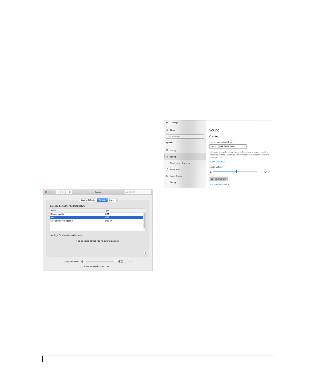
3 Click Sound and choose the M2, M4 or M6 as
the input and output device.
If your computer has USB-C ports, use a
USB-C to USB-C cable (rated for USB2), or a
USB-C to USB-A adapter, (both sold separately).
3 Go to the Windows Sound Control Panel and
choose MOTU M Series as the default input and
output device.
4 Go to Step 5 below.
FOR ALL USERS
5 Connect speakers and/or a pair of headphones
to the M series interface so you can hear your
computer’s audio output. For speakers, connect
them to the outputs on the back panel.
4 Go to Step 5 below.
FOR WINDOWS USERS
1 BEFORE you connect the M series interface to
your computer, visit motu.com/m2-start,
motu.com/m4-start or motu.com/m6-start to
download and install the Windows driver.
2 Connect the M series interface to your PC
using the included USB cable.
6 You are now ready to start using your M series
interface.
7 Vi sit motu.com/m2-start, motu.com/m4-start or
motu.com/m6-start to register your product,
download the included software and watch brief
how-to videos, including:
Q
How to connect a mic, guitar, keyboard or other
line-level audio source.
Q
How to use your M series interface with your
recording software.
5
Page 6

Q
How to get the most out of your M series
interface.
PLEASE REGISTER TODAY
Please visit motu.com/m2-start, motu.com/
m4-start or motu.com/m6-start to register your
M series interface and gain access to all the
software, virtual instruments, loops and sounds
that are included with your purchase. Registered
users also qualify for technical support and
information about software updates, so please
register today!
Thank you for t aking t he time to register your new
MOTU product!
FINDING YOUR SERIAL NUMBER
You can find your M series product serial number
on the bottom of the unit and the side of the box.
6
Page 7
M2 Quick Reference
1 4
9
2
10
3 5
11 12
678
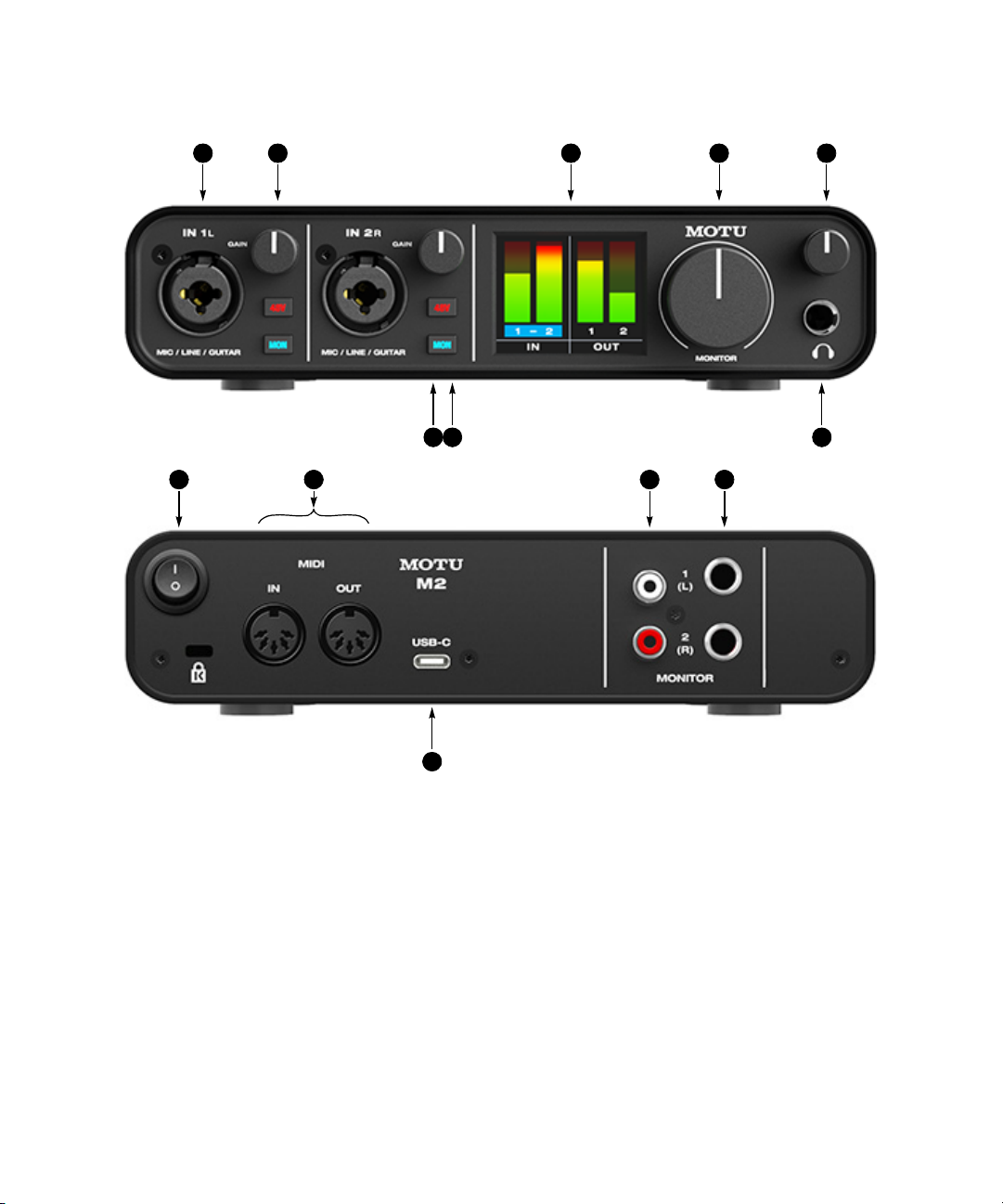
1. These two XLR/TRS combo jacks accept a mic cable or a
quarter-inch cable, balanced or unbalanced, from a guitar
or line level source.
2. Use GAIN knob to add up to 60 dB of boost to the input
signal. Watch the input level meter in the LCD while
adjusting gain. Try to adjust gain as high as possible
without clipping, which is indicated by the red rectangle at
the top of the meter.
3. The full-color, high-resolution LCD (160x120 pixels) shows
full-length meters for all inputs and outputs. An
overloade d signal is i ndicated by a re d box at the top o f the
signal. If you see the red box, reduce the signal level. A blue
box around the input channel number indicates that
hardware (direct) monitoring (the MON button) is
engaged for that channel.
4. Volume control for the MONITOR outputs on the back
panel.
5. Volume control for headphone output.
13
6. Connect your headphones here. This signal matches the
signal on the MONITOR outputs on the rear panel, but
volume control (5) is independent.
7. Engage the 48V button to turn on phantom power for a
condenser microphone connected to the input.
8. Engage the MON (monitor) button to enable hardware
(direct) monitoring, which routes the channel’s in put
signal directly to the outputs and pans the mono signal
evenly across both outputs (1-2). A blue box appears
around the inp ut channel number in th e LCD to indicate
that hardware monitoring is engage. Press and hold the
MON button to engage stereo monitoring for both inputs.
In this mode, Input 1 is routed to Output 1 and Input 2 is
rou te d to Ou tpu t 2 , a ll owi ng y ou to m on ito r i n st er eo w hi le
recording in stereo.
9. POWER SWITCH: You can switch off the M2 and turn it back
on without restarting your computer.
10. Connect MIDI gear to these standard MIDI ports.
11. These unbalanced RCA analog outputs mirror the signal on
the quarter-inch outputs (12). You can connect them to a
second set of speakers or other destination.
12. Connect these balanced, DC-coupled quarter-inch outputs
to your studio speakers, PA or other desired audio destination. They can also accept an unbalanced plug.
Note: the analog outputs are not cross-coupled. Therefore,
when connecting them to an unb alanced input, use a TRS
plug with the ring disconnected. Not floating the negative
terminal will short it to the sleeve ground and cause
distortion.
13. Connect the M2 to your host computer with the supplied
USB-C to USB-A cable. If your computer has USB-C ports,
use a USB-C to USB-C cable (rated for USB2) or a USB-A
adapter (both sold separately). The M2 is powered by its
USB connection to the host computer. For information
about connecting to an iOS device, see “Connecting to an
iOS device” on page 18.
Page 8
M4 Quick Reference
1 5
2
3
4 6
8
11
12
13 14
7910
15
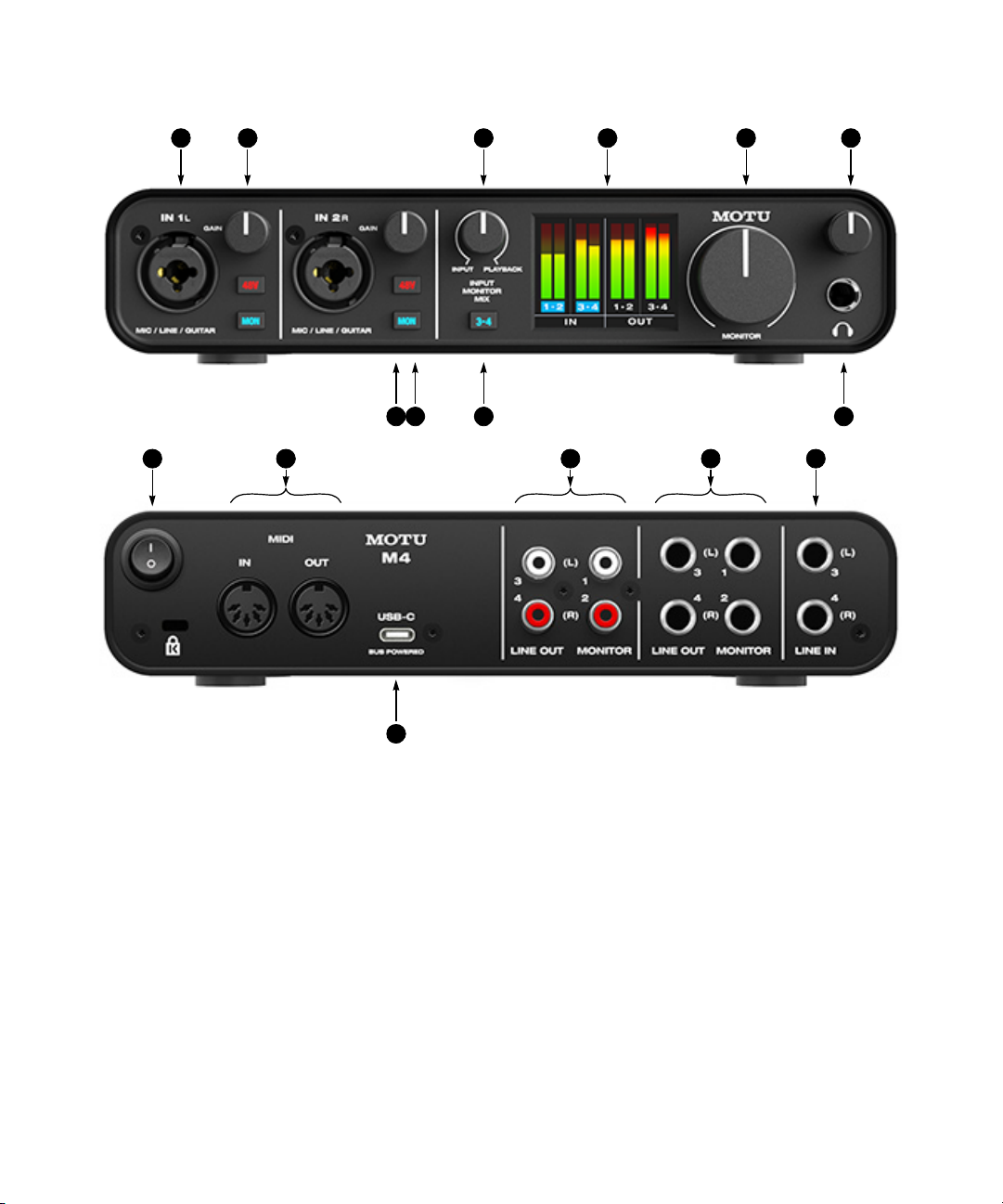
1. These two XLR/TRS combo jacks accept a mic cable or a
quarter-inch cable, balanced or unbalanced, from a guitar
or line level source.
2. Use GAIN knob to add up to 60 dB of boost to the input
signal. Watch the input level meter in the LCD while
adjusting gain. Try to adjust gain as high as possible
without clipping, which is indicated by the red rectangle at
the top of the meter.
3. INPUT MONITOR MIX: Controls the balance (relative
volume) be tween computer outp ut (over USB) and live
inputs being monitored through the hardware using the
MON (monitor) button (10). Turn it counterclockwise to
hear more input s; turn it clockwise to hear more computer
audio.
4. The full-color, high-resolution LCD (160x120 pixels) shows
full-length meters for all inputs and outputs. An
overloade d signal is i ndicated by a re d box at the top o f the
signal. If you see the red box, reduce the signal level. A blue
box around the input channel number indicates that
hardware (direct) monitoring (the MON button) is
engaged for that channel.
5. Volume control for the MONITOR outputs on the back
panel.
6. Volume control for headphone output.
16
7. Connect your headphones here. This signal matches the
signal on the MONITOR outputs on the rear panel, but
volume control (6) is independent.
8. Engages hardware (direct) monitoring for inputs 3-4 on
the rear panel. See (10) below for more information.
9. Engage the 48V button to turn on phantom power for a
condenser microphone connected to the input.
10. Engage the MON (monitor) button to enable hardware
(direct) monitoring, which routes the channel’s in put
signal directly to the outputs and pans the mono signal
evenly across both outputs (1-2). A blue box appears
around the inp ut channel number in th e LCD to indicate
that hardware monitoring is engage. Press and hold the
MON button to engage stereo monitoring for both inputs.
In this mode, Input 1 is routed to Output 1 and Input 2 is
rou te d to Ou tpu t 2 , a ll owi ng y ou to m on ito r i n st er eo w hi le
recording in stereo.
11. POWER SWITCH: You can switch off the M4 and turn it back
on without restarting your computer.
12. Connect MIDI gear to these standard MIDI ports.
13. These unbalanced RCA analog outputs mirror the signal on
their correspon ding quarter-inch out puts (14). You can
connect them to a second set of speakers or other destinations.
14. Connect these balanced, DC-coupled quarter-inch outputs
to your studio speakers, PA or other desired audio destination. They can also accept an unbalanced plug. Each output
pair is independent and can be found as separate output
pairs in your host software.
Note: the analog outputs are not cross-coupled. Therefore,
when connecting them to an unb alanced input, use a TRS
plug with the ring disconnected. Not floating the negative
terminal will short it to the sleeve ground and cause
distortion.
15. These LINE INPUTS accept either a balanced or unbalanced
plug. Connect a keyboard or other similar line level audio
source.
16. Connect the M4 to your host computer with the supplied
USB-C to USB-A cable. If your computer has USB-C ports,
use a USB-C to USB-C cable (rated for USB2) or a USB-A
adapter (both sold separately). The M4 is powered by its
USB connection to the host computer.
Page 9
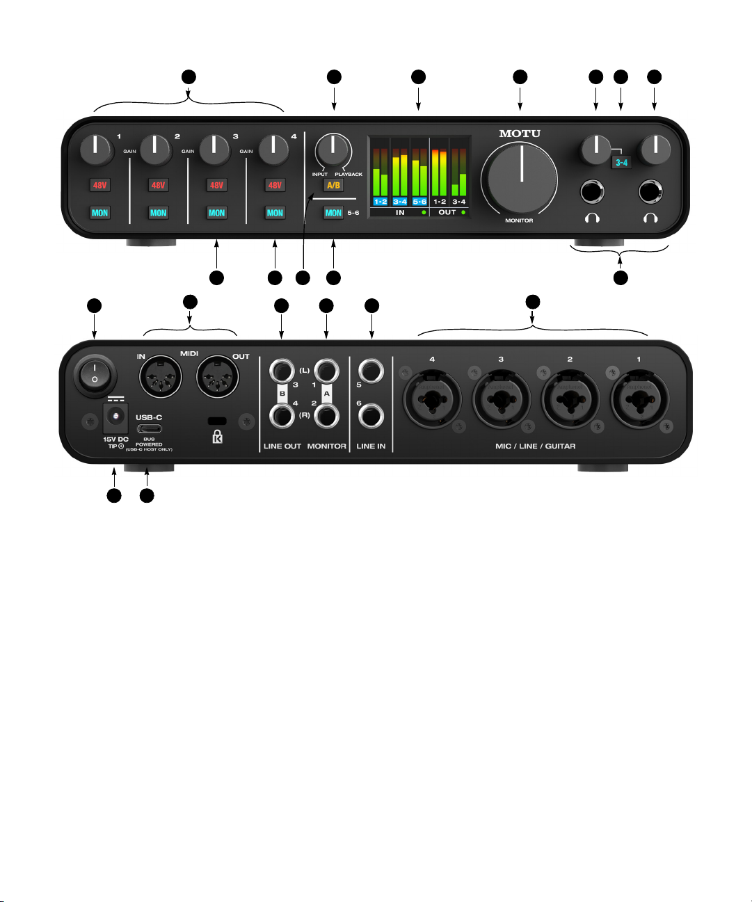
M6 Quick Reference
1 6 7
2
3 5
4
12
13
19
20
1. Use these GAIN knobs to add up to 60 dB of boost to the input
signal for each mic input. Watch the input level meter in the LCD
while adjusting gain. Try to adjust gain as high as possible
without clipping, which is indicated by the red rectangle at the
top of the meter.
2. INPUT MONITOR MIX: Controls the balance (relative volume)
between computer output (over USB) and live inputs being
monitored throug h the hardware using the MON (moni tor)
button (12). Turn it counterclockwise to hear more inputs; turn
it clockwise to hear more computer audio.
3. The full-color, high-resolution LCD (160x120 pixels) shows fulllength meters for all inputs and outputs. An overloaded input
signal is indicated by a red box at the top of the signal. If you see
the red box, reduce the signal level. A blue box around the input
channel number indicates that hardware (direct) monitoring
(the MON button) is engaged for that channel.
4. Volume control for the MONITOR outputs on the back panel. If
you are using the A/B speaker select mode, this controls the
volume of either your A speakers or B speakers (whichever is
currently selected).
5. Volume control for headphone output below it.
6. Both headphone outputs mirror the signal on the MONITOR 1-2
outputs (on the rear panel). Engage the 3-4 switch to monitor
LINE OUT 3-4 instead on this headphone output. This allows you
to set up a separate mix from your host software for this
headphone output.
7. Volume control for headphone output below it.
14
9
15 16 17
8. Connect your headphones here. This signal matches the signal
on the MONITOR 1-2 outputs on the rear panel, but volume
control (5 and 7) is independent.
9. Engages hardware (direct) monitoring for input s 5-6 on the
rear panel. See (12) below for more information.
10. Press and hold the A/B switch to enable or disable A/B mode.
When enabled, you can connect a 2nd pair of “B” monitors to
Line Out 3-4. Then, quickly press the A/B button to switch
between the A monitors (connected to MONITOR Outs 1-2) and
the B monitors (connected to Line Out 3-4) to compare your mix
on the two sets of monitors. For details, see “A/B monitor
switching on the M6” on page 19.
11. Engage the 48V button to turn on phantom power for a
condenser microphone connec ted to the input.
12. Engage the MON (monitor) button to enable hardware (direct)
monitoring, which routes the channel’s input signal directly to
the MONITOR 1-2 outputs and pans the mono signal evenly
across both outputs. A blue box appears around the input
channel number in the LCD to indicate that hardware monitoring is engage. Press and hold the MON button to engage stereo
monitoring for input pairs. In this mode, Input 1 is routed to
Output 1 and Input 2 is routed to Output 2, allowing you to
monitor in stereo while recording in stereo. Inputs 3-4 are
similarly routed to Outputs 1 and 2 (3 to 1 and 4 to 2).
13. POWER SWITCH: You can switch off the M6 and turn it back on
without r estarting you r computer.
14. Connect MIDI gear to these standard MIDI ports.
81011
18
15. Connect these balanced, DC-coupled quarter-inch outputs to
your secondary (B) studio speakers, PA or other desired audio
destination. They can also accept an unbalanced plug (see the
note below about unbalanced connections). Each output pair is
independent and can be found as separate output pairs in your
host software.
16. Connect these balanced, DC-coupled quarter-inch outputs to
your primary (A) studio speakers, PA or other desired audio
destination. They can also accept an unbalanced plug. Each
output pair is independent and can be found as separate output
pairs in your host software.
Note: the analog outputs are not cross-coupled. Therefore,
when connecting them to an unbalanced input, use a TRS plug
with the ring disconnected. Not floating the negative terminal
will short it to the sleeve ground and cause distortion.
17. These LINE INPUTS accept either a balanced or unbalanced
plug. Connect a keyboard or other similar line level audio
source.
18. These four XLR/TRS combo jacks accept a mic cable or a quarterinch cable, balanced or unbalanced, from a guitar or line level
source.
19. Connect the M6 to your host computer with the supplied USB
cable. When the M6 is connected to a USB-C host computer or
iPad, it can be powered by its USB connection to the host. When
connected to a USB-A host computer, you’ll need to connect the
DC power adapter to supply enough power.
20. Connect the DC power adapter here. It is optional, unless the
M6 is connected to a USB-A host that cannot supply enough bus
power. You can also power the M6 when no host is connected.
Page 10

CHAPTER
1
Packing List and System Requirements
PACKING LIST
M series interfaces ship with the items listed
below. If any of these items are not present in the
box when you first open it, please immediately
contact your dealer or MOTU.
Q
One M2, M4 or M6 audio interface
Q
USB-C to USB-A cable
Q
DC power adapter (M6 only)
Q
Safety instruction sheet
SYSTEM REQUIREMENTS
Q
Intel Core i3 Mac or faster (including Apple
silicon Macs) or 1 GHz Pentium-based PC (or
compatible). Faster CPUs are recommended for
best performance.
Q
2 GB RAM; 4 GB or more recommended.
Q
macOS 10.11 or later (optional driver requires
10.13 or later); Windows 10 or later (x64 only).
Q
Available high-speed USB 2.0 (or 3.0) port.
Q
A large hard drive (preferably at least 512 GB).
PLEASE REGISTER TODAY!
Please visit the link below that applies to you to
register your M series interface and gain access to
all the software, virtual instruments, loops and
sounds that are included with your purchase.
Registered users also qualify for technical support
and information about software updates, so please
register today!
Q
motu.com/m2-start
Q
motu.com/m4-start
Q
motu.com/m6-start
Thank you for taking the time to register your new
MOTU product!
FINDING YOUR SERIAL NUMBER
You can find your M series product serial number
on the bottom of the unit and the side of the box.
10
Page 11

CHAPTER
2
Software Installation
OVERVIEW
USB audio class-compliant operation . . . . . . . . . . . . . . . . . . 11
Driver installation . . . . . . . . . . . . . . . . . . . . . . . . . . . . . . . . . . . . 11
M series Control Panel (Windows only) . . . . . . . . . . . . . . . . . 12
MIDI I/O on Windows . . . . . . . . . . . . . . . . . . . . . . . . . . . . . . . . . 13
MIDI I/O setup on the Mac. . . . . . . . . . . . . . . . . . . . . . . . . . . . . 13
Working with host audio software . . . . . . . . . . . . . . . . . . . . . 14
USB AUDIO CLASS-COMPLIANT OPERATION
Your M Series interface is a USB audio classcompliant device. This means that you can
connect it to your Mac (running macOS 10.11 or
higher) with a USB cable and use it without
installing any software drivers. The computer
recognizes your M Series interface as a USB audio
device and makes its inputs and outputs available
to your host audio software. Basic settings, such as
the hardware’s sample rate, are made in your host
software.
In this scenario, your M Series interface
provides basic audio input and output, and no
software driver installation is necessary. Use the
Mac’s Audio MIDI Setup utility to manage your M
Series interface audio inputs and outputs for your
Mac.
Connection to iOS devices (iPad and iPhone)
Audio-class compliant operation allows you to
connect your M Series interface to any iOS device
to provide multi-channel audio I/O to your audio
apps. Use your audio app to configure the number
of available audio channels.
For iOS devices with a USB-C port, a USB-C
to USB-C cable is required.
For iOS devices with a Lightning port, an
Apple Lightning to USB3 Camera Adapter is
required (sold separately).
DRIVER INSTALLATION
Driver installation is required for either of the
following scenarios:
Q
You are using a PC running Windows (10 or
later).
Q
You are using a Mac and you wish to take
advantage of the extra features that the driver
provides: lower latency performance and loopback
channels (see “Loopback” on page 23).
If neither scenario applies to you, then you can
skip software installation if you wish, and proceed
to chapter 3, “Hardware Installation” (page 15).
Download and run the M Series installer
To download the latest M Series installer for Mac
or Windows, visit www.motu.com/m2-start (it’s
the same installer for the M2, M4 and M6). Follow
the directions that the installer gives you.
We recommend that you run the software
installer before you connect your M Series
interface to your computer and power it on.
Industry-leading I/O latency performance
On macOS and Windows, the M series driver
provides exceptionally low I/O latency
performance. For example, with a 32-sample
buffer size, an M Series interface operating at 96
kHz produces round trip latency (RTL)
performance of 2.5 milliseconds (ms) on
Windows and 2.5 ms on macOS. RTL is the
measurement of the time it takes audio to pass
from an analog input, through a DAW host, to an
analog output.
11
Page 12
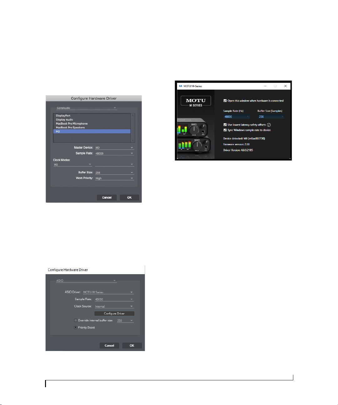
M Series Core Audio driver for macOS
On macOS, to enable your M Series interface in
your Core Audio-compatible host software, go to
the menu item or preference in your host audio
software where you choose the audio device (Core
Audio driver) you wish to use, and then select the
M2, M4 or M6 by name.
Figure 2-1: Choosing the M Series Core Audio driver in Performer Lite on
Windows (S etup menu > Configure A udio System > Config ure
Hardware D river).
M Series ASIO driver for Windows (x64 only)
On Windows, to enable your M Series interface in
your ASIO host software, choose M Series ASIO
driver.
M SERIES CONTROL PANEL (WINDOWS ONLY)
On Windows, you can access the M Series control
panel in the Windows Start menu. In Performer
Lite, you can access it by clicking the Configure
Driver button shown in Figure 2-2.
Figure 2-3: M Series control panel.
Sample Rate (Hz)
Choose the desired sample rate (Figure 2-3) for
operation with your host software. Make sure your
host software matches the sample rate you choose
here.
Buffer Size
The Buffer Size setting (Figure 2-1 and Figure 2-3)
determines the amount of latency (delay) you may
hear when live audio is patched through your host
audio software. Smaller buffer sizes produce lower
latency, with sizes of 256 samples or less producing
virtually imperceptible delay. Many host
applications report audio hardware I/O latency, so
you can see what happens to the reported latency
when making adjustments to this setting.
Figure 2-2: Choosing the M Series ASIO driver in Performer Lite on
Windows (S etup menu > Configure A udio System > Config ure
Hardware D river).
SOFTWARE INSTALLATION
Be careful with very small buffer sizes, as they can
cause performance issues from your host software
or PC.
At sea level, audio travels approximately one
foot (30 cm) per millisecond. A latency of ten
milliseconds is about the same as being ten feet
(three meters) from an audio source.
12
Page 13
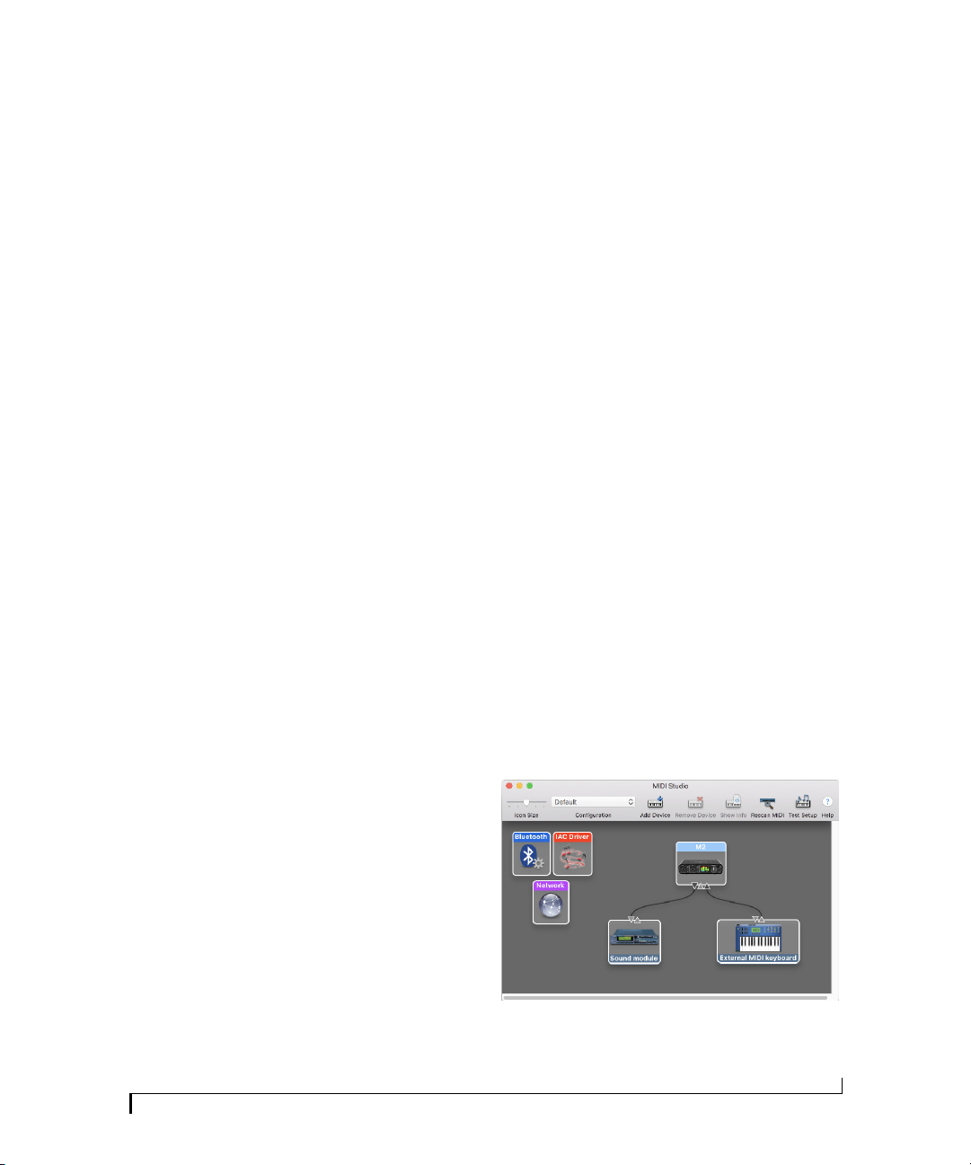
Use lowest latency safety offsets
Enable the Use lowest latency safety offsets option
(Figure 2-3) for the best possible low-latency
performance from the driver. Note: some
computer systems may not handle this option well.
If you hear artifacts in your audio (clicks, pops,
glitches, etc.), disable this option.
Sync Windows sample rate to device
Enable the Sync Windows sample rate to device
option (Figure 2-3) to link this sample rate setting
with the Sample Rate setting in Windows. This
option is enabled by default for best performance
with many Windows audio applications.
MIDI I/O ON WINDOWS
On Windows, the M Series driver installer
provides a USB MIDI driver for your M Series
interface. This driver allows you to access the their
MIDI input and output ports through its USB
connection to the computer. The ports are
published in Windows and are available to all
MIDI software.
Launching Audio MIDI Setup
1 Make sure your M Series interface is connected
(a USB connection is required) and turned on.
2 Launch the Audio MIDI Setup utility.
This can usually be found in /Applications/
Utilities. If it has been moved, just search for
Audio MIDI Setup.
3 Confirm that the MIDI interface is present in
the MIDI Devices tab (or window) in Audio MIDI
Setup. If the interface does not appear, or if it is
grayed out, check your cable connections and click
Rescan MIDI.
Connecting MIDI devices to the M Series
Once your M Series interface appears in Audio
MIDI Setup, you are ready to add devices, indicate
how they are connected, and identify properties
they may have for particular purposes. This
information is shared with all Core MIDI
compatible applications.
MIDI I/O SETUP ON THE MAC
Core MIDI is the “under-the-hood” component of
macOS that handles MIDI services for MIDI
hardware and software. Core MIDI provides many
universal MIDI system management features,
including MIDI communication between your M
Series interface and all Core MIDI compatible
software.
Audio MIDI Setup is a utility included with macOS
that allows you to configure your M Series
interface for use with all Core MIDI compatible
applications. Audio MIDI Setup provides:
Q
A “virtual” studio on your Mac that graphically
represents your MIDI hardware setup and that is
shared by all Core MIDI-compatible programs
Q
A simple, intuitive list of your MIDI devices
whenever you need it in any Core MIDIcompatible program
SOFTWARE INSTALLATION
To add a device in Audio MIDI Setup:
1 Click Add Device.
2 Drag on its input and output arrows to draw
connections to the M Series interface that match
its physical connection.
Figure 2-4: Connecting devices to an M Series interface. In this example,
a controller keyboard is connected to the M2 MIDI IN, and a sound
module is connected to the M2 MIDI OUT.
13
Page 14
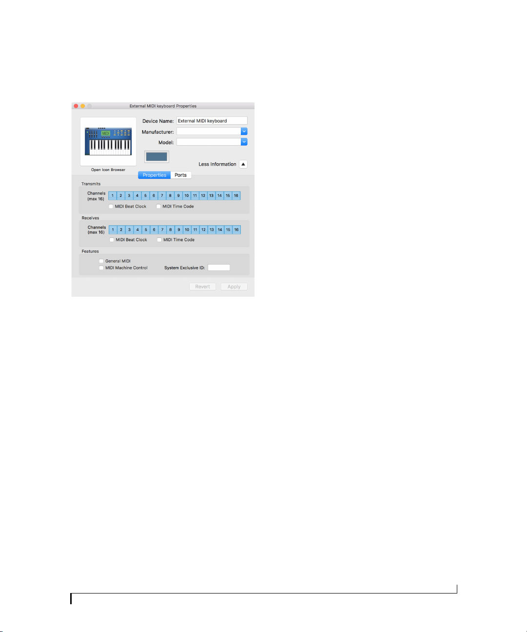
3 Double-click the device to make settings, such
as input and output channels, that further describe
the device.
Figure 2-5: Device settings.
4 Repeat the above steps for each MIDI device
connected to the interface.
5 When you are finished, quit Audio MIDI Setup.
Your configuration is automatically saved as the
default configuration, and it is shared with all
Core MIDI-compatible software.
WORKING WITH HOST AUDIO SOFTWARE
For further information about using your M Series
interface with host audio software, see chapter 4,
“Working with Host Audio Software” (page 21).
SOFTWARE INSTALLATION
14
Page 15
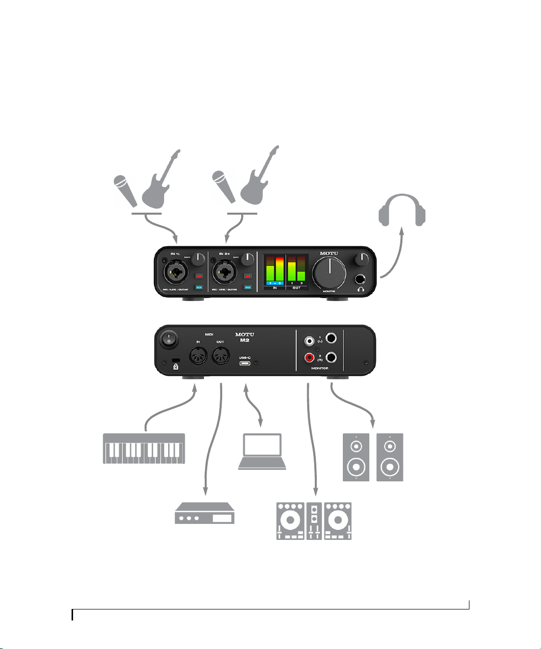
3
Figure 3-1: A typical M2 studio setup.
Mic
or
guitar
Mic
or
guitar
Headphones
MIDI controller
or synthesizer
MIDI synth
Mac or PC
DJ system
Speakers
CHAPTER
Hardware Installation
A TYPICAL M2 SETUP
15
Page 16
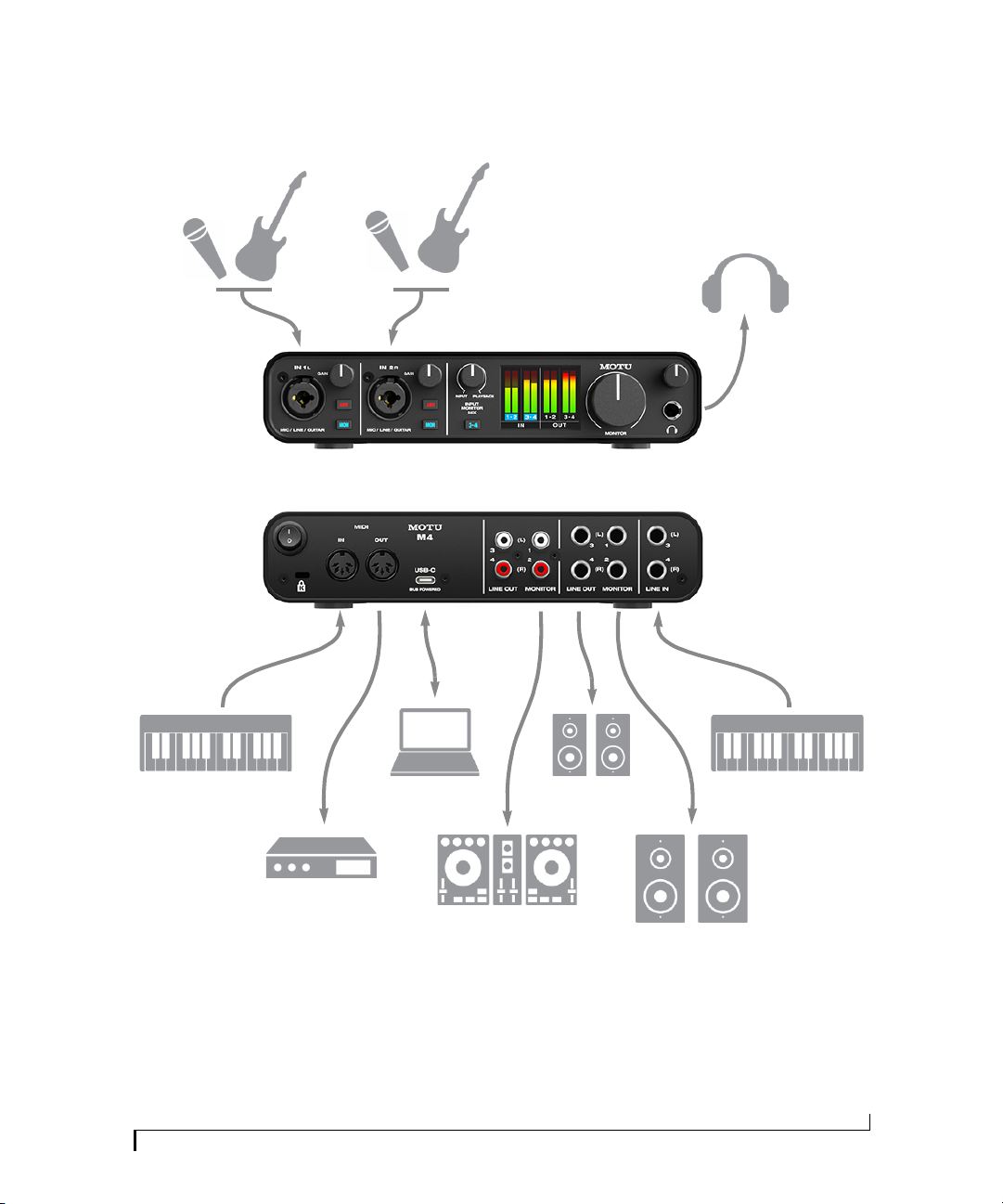
A TYPICAL M4 SETUP
Figure 3-2: A typical M4 studio setup.
Mic
or
Guitar
Mic
or
Guitar
Headphones
MIDI controller
or synthesizer
MIDI synth
Mac or PC
DJ system
A speakers
B speakers
MIDI controller
or synthesizer
HARDWARE INSTALLATION
16
Page 17
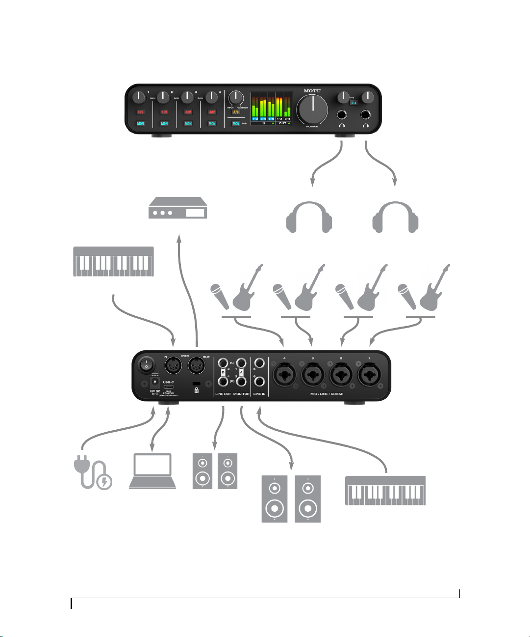
A TYPICAL M6 SETUP
Figure 3-3: A typical M6 studio setup.
Mic
or
Guitar
Mic
or
Guitar
Headphones
MIDI controller
or synthesizer
MIDI synth
Mac or PC
A speakers
B speakers
Keyboar d
synth
Headphones
Mic
or
Guitar
Mic
or
Guitar
MIDI controller
or synthesizer
Power adapte r
(Only require d
for USB-A hosts)
HARDWARE INSTALLATION
17
Page 18
USB power
adapter
Powere d
USB hub
AC power
iOS device
CONNECTING TO A MAC OR PC
Connect the M Series interface to your host
computer with the supplied USB-C to USB-A
cable. If your computer has USB-C ports, use a
USB-C to USB-C cable (rated for USB2) or a
USB-A adapter (both sold separately).
POWER
The M2 and M4 are powered by the USB
connection to the host computer. The power
requirements for the M6 depend on the host
computer or iOS device, as follows:
Host Type Power source
Computer with a USB-C port USB connection (or, optionally, the
Computer with a USB-A port Power adapter (required)
iOS device with USB-C port USB connection (or, optionally, the
iOS device with Lightning port USB3 camera adapter (see below)
power adapter)
power adapter)
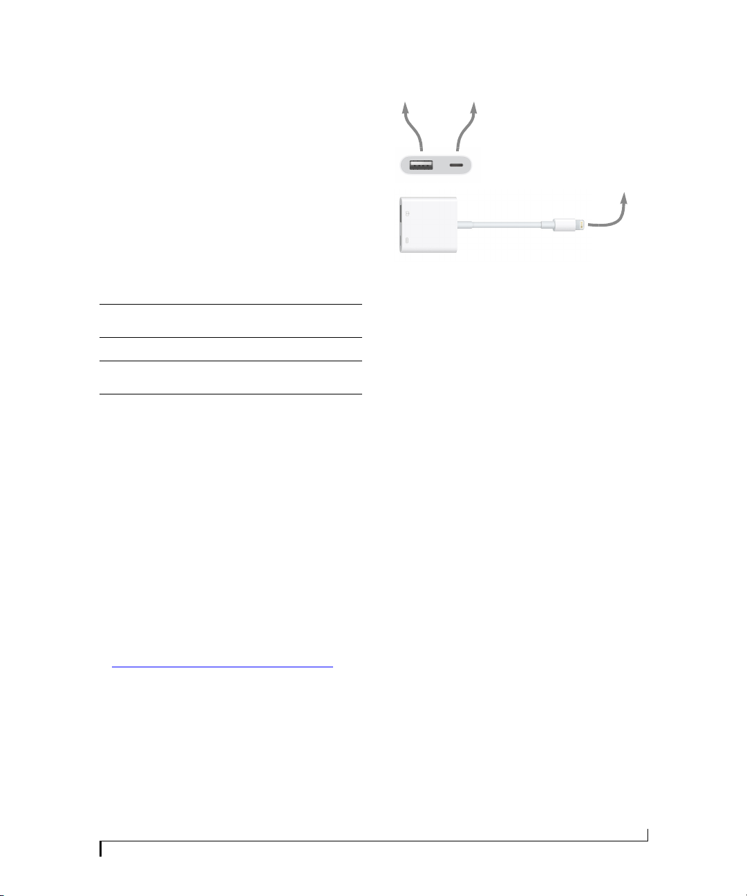
CONNECTING TO AN iOS DEVICE
Recent-generation Apple iOS devices have two
types of connectors: Lightning or USB-C.
For iOS devices with a USB-C port, simply
connect the M Series interface directly to the iOS
device with a standard USB-C-to-C cable (sold
separately).
For iOS devices with a Lightning port, the
following is required (to supply enough power):
Q
Powered USB hub
Q
Apple Lightning to USB3 Camera Adapter
Figure 3-4: The Apple Lightning to USB3 Camera Adapter.
Connect the M Series interface to a USB port on
the powered USB hub. Connect the powered USB
hub host port to the camera adapter with a USB
cable. Connect the camera adapter Lightning port
to the iOS device Lightning port, as shown in
Figure 3-4.
AUDIO CONNECTIONS
Here are a few things to keep in mind as you are
making audio connections to your M Series
interface.
Mic/line/instrument inputs with preamps
Connect a microphone, guitar or line-level analog
input to the XLR/quarter-inch combo jacks with
either a standard mic cable or a balanced cable
with a quarter-inch plug.
Do not connect a +4 (line level) XLR cable to
the inputs (because of the preamps). Use a
quarter-inch input instead.
Phantom power
If you are connecting a condenser microphone or
another device that requires phantom power,
engage the corresponding 48V phantom power
switch.
HARDWARE INSTALLATION
Preamp gain
The M series preamps provides 60 dB of gain. Use
the front panel trim knobs to adjust gain as needed
for each input. Watch the input level meter in the
18
Page 19

LCD while adjusting gain. Try to adjust gain as
high as possible without clipping, which is
indicated by the red rectangle at the top of the
meter.
Combo jack summary
Use these guidelines for 48V phantom power and
trim settings on the two combo input jacks:
Input
Condenser mic On As needed
Dynamic mic Off As needed
Guitar Off As needed
Line level Off Zero
48V Trim
TRS quarter-inch analog inputs and outputs
Quarter-inch analog inputs and outputs are
balanced (TRS) connectors that can also accept an
unbalanced plug. The outputs are DC-coupled, so
they can be used for CV control output.
Quarter-inch analog outputs are not
cross-coupled. Therefore, when connecting them
to an unbalanced input, use a TRS plug with the
ring disconnected. Not floating the negative
terminal will short it to the sleeve ground and
cause distortion.
Unbalanced RCA outputs (M2 and M4 only)
Connect the unbalanced RCA outputs to other
gear that has similar unbalanced RCA inputs, such
as DJ systems, karaoke equipment or consumer
audio devices.
A/B monitor switching on the M6
If you have an M6 and two different sets of studio
monitors, and you would like to be able to switch
between them to compare how your mixes sound
on each pair, connect your primary monitors (A)
to the MONITOR 1-2 outputs and connect the
secondary monitor pair (B) to LINE OUT 1-2.
Then press and hold the A/B switch on the front
panel. Doing so engages A/B mode. In this mode,
you can then quickly press the A/B button to
switch between the A speakers and B speakers.
More specifically, in A/B mode, LINE OUT 1-2 no
longer function as independent outputs. instead,
they mirror the signal on the MONITOR 1-2
outputs, and the A/B switch controls which pair
plays (while the other is muted).
To exit A/B mode, press and hold the A/B switch.
Headphones
Connect your headphones to the headphone
output on the front panel. The headphone output
mirrors the signal on the MONITOR 1-2 outputs.
Use the volume knob above it to control its volume
independently. The M6 has two headphone
outputs. Both mirror the signal on the MONITOR
1-2 outputs and have their own independent
volume control. One of the headphone outputs has
a 3-4 switch. When engaged, the output mirrors
the signal on LINE OUT 3-4 instead. This allows
you to set up a separate headphone mix from your
host software (on outputs 3-4).
Monitor outs
In a standard studio configuration, the monitor
outs are intended for a pair of primary studio
monitors, but they can be used as regular outputs
for any purpose.
HARDWARE INSTALLATION
19
Page 20
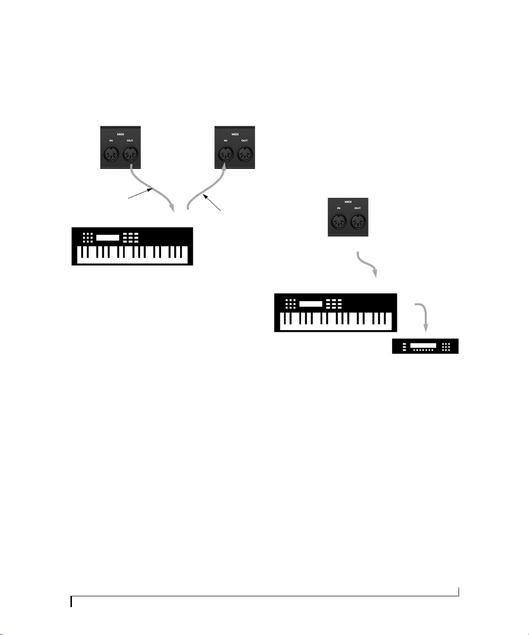
MIDI CONNECTIONS
M Series
rear panel
MIDI Device
MIDI
cables
MIDI INMIDI
OUT
MIDI
OUT
MIDI
IN
Conne ction A
Connec tion B
MIDI IN
MIDI
cable
MIDI Device
MIDI
IN
MIDI
THRU
MIDI
OUT
M Series
rear p anel
Connect your MIDI device’s MIDI IN jack to the
M series MIDI OUT jack (Connection A below).
Conversely, connect the MIDI device’s MIDI OUT
jack to the M Series MIDI IN jack (Connection B).
Figure 3-5: Connecting a MIDI device to an M Series interface.
One-way MIDI connections
MIDI devices that do not receive MIDI data, such
as a dedicated keyboard controller, guitar
controller, or drum pad, only need Connection B
shown in Figure 3-5. Similarly, devices that never
send data, such as a sound module, only need
Connection A. Make both connections for any
device that needs to both send and receive MIDI
data.
Connecting additional gear with MIDI THRUs
If you need to connect several pieces of MIDI gear,
run a MIDI cable from the MIDI THRU of a
device already connected to the M Series interface
to the MIDI IN on the additional device as shown
below in Figure 3-6. The two devices then share
the M Series MIDI OUT port. This means that
they share the same set of 16 MIDI channels, too,
so try to do this with devices t hat lis ten to only one
MIDI channel (such as effects modules), which
makes it easier to avoid MIDI channel conflicts.
Figure 3-6: Connecting additional devices with MIDI THRU ports.
HARDWARE INSTALLATION
20
Page 21
CHAPTER
4
Working with Host Audio Software
OVERVIEW
M Series interfaces provide multi-channel audio
input and output for Core Audio compatible audio
applications on the Mac and ASIO compatible
applications on Windows, including MOTU’s
Performer Lite and Digital Performer, Apple’s
Logic Pro and GarageBand, and other third-party
software applications such as Ableton Live, Avid
Pro Tools, Cockos Reaper, Propellerhead Reason,
Steinberg Cubase and Nuendo, PreSonus Studio
One, Bitwig, and others.
Performer Lite and Ableton Live Lite are both
available as a free download for M Series owners at
motu.com. Just log in to your account and go to
your Product Registrations tab. For complete
information about all of Performer Lite’s powerful
workstation features, refer to the Performer Lite
User Guide.pdf found in the Help menu of the
Performer Lite application.
Digital Performer, MOTU’s state-of-the-art digital
audio workstation software, is available separately;
for details about upgrading from Performer Lite to
Digital Performer, talk to your authorized MOTU
dealer or visit motu.com.
CHOOSING THE M SERIES DRIVER
For macOS audio software
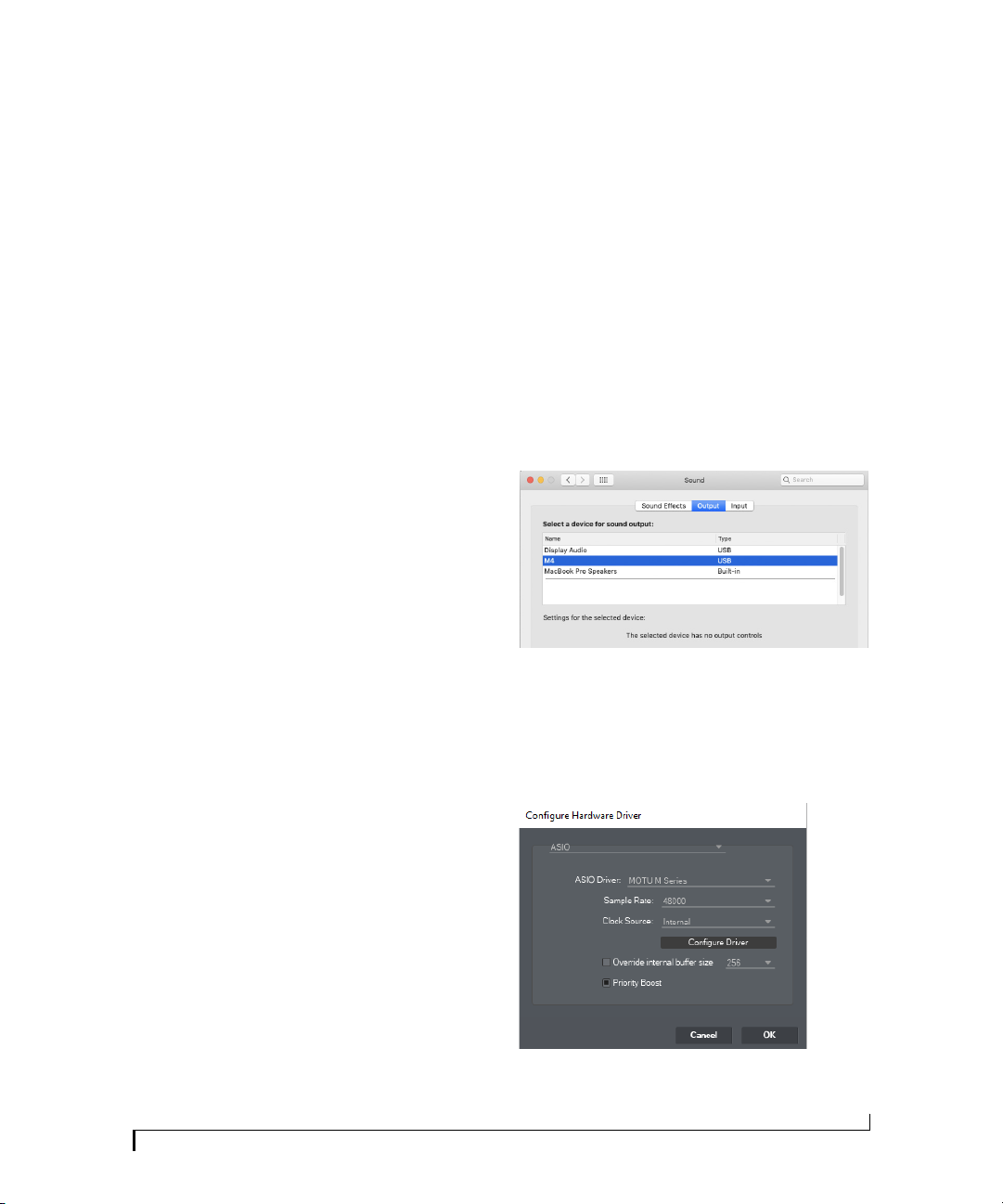
For macOS, go to the Sound control panel and
choose the M2, M4 or M6 for input and output. If
you’ve installed the M series driver for macOS, go
to the menu item or preference in your host audio
software where you choose the audio device (Core
Audio driver) you wish to use, and then select the
M2, M4 or M6 by name (see Figure 2-1 on
page 12).
For Windows audio software
For audio software running under Windows, go to
the menu item or preference where you choose the
ASIO driver you wish to use, and then choose
MOTU M Series.
Preparation . . . . . . . . . . . . . . . . . . . . . . . . . . . . . . . . . . . . . . . . . . 21
Choosing the M Series driver . . . . . . . . . . . . . . . . . . . . . . . . . . 21
Reducing monitoring latency . . . . . . . . . . . . . . . . . . . . . . . . . . 22
Loopback . . . . . . . . . . . . . . . . . . . . . . . . . . . . . . . . . . . . . . . . . . . . 23
PREPARATION
Install your host audio software first if you haven’t
already done so, and complete these chapters
before proceeding:
Q
chapter 2, “Software Installation” (page 11)
Q
chapter 3, “Hardware Installation” (page 15)
Figure 4-1: Choosing the M Series ASIO driver in Performer Lite on
Windows (Set up menu > Configure Au dio System > Configure
Hardware D river).
21
Page 22

Where to go in popular audio hosts
Here is the location for this setting in various
popular audio software host applications:
Host software
Digital Performer
and Performer Lite
Pro Tools 9 or later Setup menu > Playback Engine or Current
Location for choosing the M series interface
Setup menu > Configure Audio System >
Configure Hardware Driver
Engine
Monitoring through the M series interface
If you don’t need to process a live input with
plug-ins, the easiest way to avoid monitoring
latency is to disable your DAW’s live monitoring
feature and instead engage the MON (monitor)
switch on the front panel of your M Series
interface. Visit motu.com/m2-start (or /m4-start
or /m6-start) to watch a video about this feature.
Logic Pro Preferences > Audio tab > Devices tab > Core
Garage Band Garage Band menu > Preferences > Audio/
Cubase and Nuendo Device Setup > Devices list > VST Audio
Live Preferences > Audio tab
Reason Preferences > Audio preferences
Reaper Preferences > Audio prefs > Devices
Audio tab
MIDI > Audio Output/Input menus
System menu
Other audio software
Consult your software’s manual for further
information.
REDUCING MONITORING LATENCY
Monitoring latency is a slight delay caused by
running an input signal through your host audio
software and back out. For example, you might
hear it when you drive a live guitar input signal
through an amp modeling plug-in running in
your audio sequencer.
This delay is caused by the amount of time it takes
for audio to make the entire round trip through
your computer, from when it first enters an input
on the M Series interface, passes through the
interface hardware into the computer, through
your host audio software, and then back out to an
output.
Monitoring through your host audio software
If you do need to process a live input with host
software plug-ins, or if you are playing virtual
instruments live through your MOTU audio
hardware, you can significantly reduce latency by
adjusting the audio buffer setting in your host
audio software, as explained in the next section.
It is important to note that monitoring delay
has no effect on the recording, or playback, of
audio data from disk. The actual recording and
playback is extremely precise, it is only the
monitoring of your live input signal which may be
delayed.
Adjusting your host software audio buffer
Buffers are small bundles of audio data. Your M
Series interface “speaks” to your computer in
buffers, rather than one sample at a time. The size
of these buffers determine how much delay you
hear when monitoring live inputs through your
audio software: larger buffers produce more delay;
smaller buffers produce less.
Adjusting buffer size on macOS
Under macOS, audio I/O buffer size is handled by
the host audio application (not by the M Series
Core Audio driver). Most audio software
applications provide an adjustable audio buffer
setting that lets you control the amount of delay
you’ll hear when monitoring live inputs or
processing them with software plug-ins, as shown
for Performer Lite in Figure 4-2.
WORKING WITH HOST AUDIO SOFTWARE
22
Page 23
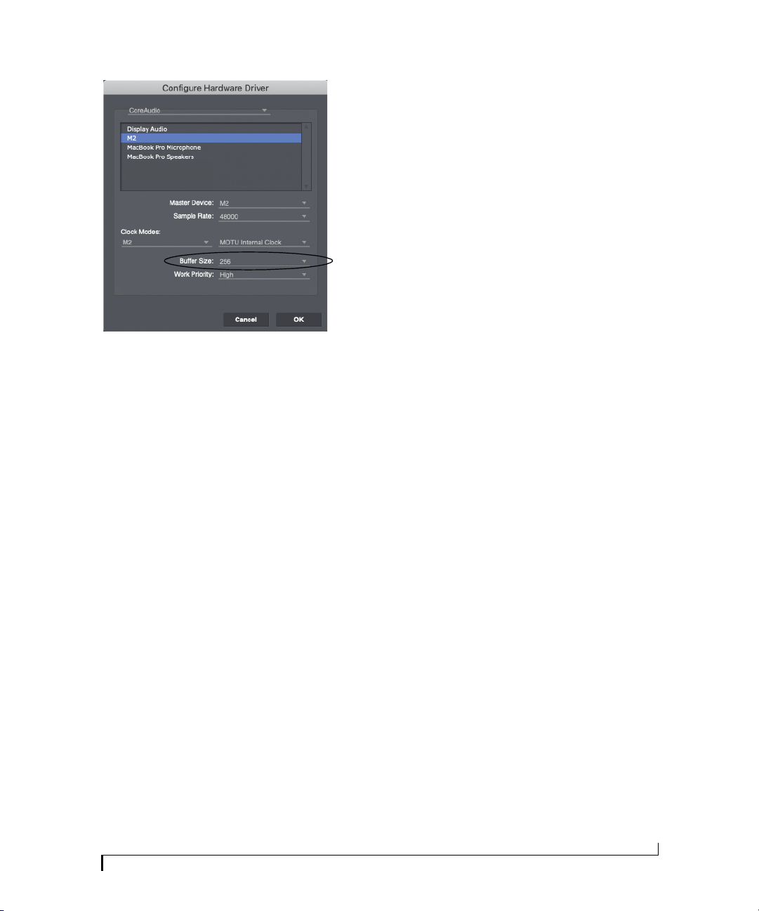
Figure 4-2: In Digital Performer and Performer Lite, choose Setup
menu> Configure Audio System> Configure Hardware Driver to open
the dialog shown above and access the Buffer Size setting.
Adjusting buffer size on Windows
On Windows, the buffer size is adjusted in the
M Series control panel (page 12). Also see “Buffer
Size”.
If you are at a point in your recording project
where you are not currently working with live,
patched-thru material (e.g. you’re not recording
vocals), or if you have a way of externally
processing inputs, choose a higher buffer size.
Depending on your computer’s CPU speed, you
might find that settings in the middle work best
(256 to 1024).
Transport responsiveness
Buffer size also impacts how quickly your audio
software will respond when you begin playback,
although not by amounts that are very noticeable.
Lowering the buffer size will make your software
respond faster; raising the buffer size will make it a
little bit slower.
Effects processing and automated mixing
Reducing latency with the buffer size setting has
another benefit: it lets you route live inputs
through the real-time effects processing and mix
automation of your audio software.
Lower latency versus higher CPU overhead
Buffer size has a large impact on the following:
Q
Monitoring latency
Q
The load on your computer’s CPU
Q
Responsiveness of transport controls and effect
knobs in Performer Lite or other audio software.
Q
Real-time virtual instrument latency.
The buffer setting presents you with a trade-off
between the processing power of your computer
and the delay of live audio as it is being patched
through your software. If you reduce the size, you
reduce monitoring latency, but significantly
increase the overall processing load on your
computer, leaving less CPU bandwidth for things
like real-time effects processing. On the other
hand, if you increase the buffer size, you reduce
the load on your computer, freeing up bandwidth
for effects, mixing and other real-time operations.
WORKING WITH HOST AUDIO SOFTWARE
LOO PBAC K
Use the Loopback 1-2 input channels provided by
the M Series audio driver to capture audio output
from your computer. These channels return the
signal being sent to Outputs 1-2 back to the
computer, as Loopback inputs 1-2, so that you can
capture the signal in your host software, stream it
to the web or broadcast it with pod casting
software.
Mixing loopback with live inputs
If you need to mix loopback channels with live
inputs, use the Loopback 1-2 Mix channels
provided by the M Series audio driver. These
channels combine audio being sent to Outputs 1-2
from the computer with any live signals on the
unit’s inputs. For example, you could play back a
music (or other audio) from your computer
software, speak or sing into a mic connected to the
23
Page 24

M series unit, and feed the combined result back
to the computer for recording or internet
streaming.
Remember, be careful! When monitoring
loopback channels and live inputs, your host
software can cause loud feedback loops. Be sure to
disable the monitoring of loopback tracks to avoid
feedback.
WORKING WITH HOST AUDIO SOFTWARE
24
Page 25

APPENDIX
A
Troubleshooting
Problem Solution Applies to
I don’t hear any sound
from my M Series
interface
How do I monitor in
stereo (or mono)
Loopback inputs don't
appear in my macOS
host software
I don’t hear any audio
on the phones output
with the 3-4 switch
“Low USB Power” The M6 must be connected to
Is the M Series selected as the
default device for input and
output for your computer and/or
host audio software?
Is the INPUT/PLAYBACK knob
set to the center position?
Is the Phones knob and/or
Monitor knob turned up?
(macOS Users) Does your host
audio software require
Microphone Access in System
Preferences > S ecurity and
Privacy?
Press and hold the MON button
to enable/disable stereo
monitoring mode.
Install the optional M Series
driver. Some DAWs will not
show the Loopback channel
names by default. Go to the link
below to see the assigned I/O
numbers to use for loopback:
https://motu.com/techsupport/
technotes/channellisting
Is 3-4 engaged? This mirrors
output channels 3-4 (Line Out),
rather than 1-2 (Monitor Out).
the DC power adapter when the
M6 is connected to a host
computer with a USB Type A
port (instead of a USB Type C
port). See “Power” on page 18.
All
M4 / M6
All
All
All
All
M6
M6
My MOTU interface isn’t showing up in Audio MIDI
Setup on my Mac.
Due to the updated architecture of the new macOS
High Sierra (10.13) or higher, the system
extensions for all newly-installed third-party
software will automatically be blocked from
running. If your MOTU interface is not showing
up in Audio MIDI Setup or your DAW on High
Sierra or higher, you might need to enable the
driver in your System Preferences. To do so, first
download and install the very latest installer for
your MOTU M Series interface. After restarting,
open System Preferences. Select Security &
Privacy. In the General section, click the Allow
button. The Allow button will disappear 30
minutes after installation. To display the Allow
button, run the installer for the MOTU driver
again.
How do I monitor live inputs?
Please refer to the documentation for the audio
application that you are using. If your application
does not support input monitoring, you will need
to use the hardware monitoring feature in your
M Series interface. Please see “Monitoring
through the M series interface” on page 22.
How do I control monitoring latency?
See “Reducing monitoring latency” on page 22.
Connecting or powering gear during operation...
It is not recommended that you connect/
disconnect, or power on/off devices connected to
the M Series interface while recording or playing
back audio. Doing so may cause a brief glitch in
the audio.
CUSTOMER SUPPORT
We are happy to provide complimentary customer
support to our registered users. If you haven’t
already done so, please take a moment to register
online at MOTU.com, or fill out and mail the
included registration card. Doing so entitles you to
technical support and notices about new products
and software updates.
TECHNICAL SUPPORT
If you are unable, with your dealer’s help, to solve
problems you encounter with your MOTU device,
you may contact our technical support
department in one of the following ways at
motu.com/support:
25
Page 26

Q
Live Chat: You can connect directly with a
technician Monday through Friday between
10 AM and 5 PM Eastern Time.
Q
Schedule a call: You can schedule a callback
time to speak with a technician by phone Monday
through Friday between 1 PM - 5 PM Eastern
time.
Q
Support ticket: You can submit an online
support ticket (TechLink) at any time, 24 hours a
day, 7 days a week. A technician will get back to
you in 1-2 business days.
Please provide the following information to help
us solve your problem as quickly as possible:
Q
The serial number of your MOTU device. This
is printed on a label placed on the bottom of the
unit a nd on the side of the box. You must be able to
supply this number to receive technical support.
Q
A brief explanation of the problem, including
the exact sequence of actions which cause it, and
the contents of any error messages which appear
on the screen.
Q
The pages in the manual that refer to the
features or operation of your MOTU Device or
Performer Lite with which you are having trouble.
Q
The version of your computer’s operating
system.
We’re not able to solve every problem immediately,
but a quick TechLink or chat may yield a
suggestion for a problem which you might
otherwise spend hours trying to track down.
If you have features or ideas you would like to see
implemented, we’d like to hear from you. Please
write to the Development Team, MOTU Inc., 1280
Massachusetts Avenue, Cambridge, MA 02138, or
use our online suggestion box at www.motu.com/
suggestions.
26
APPENDIX A: TROUBLESHOOTING
Page 27

27
Page 28

B
APPENDIX
Audio Specifications
MIC in
Connector Type Combo-style, XLR / TRS Pin 2 hot, tip hot
XLR
Impedance load 2.65 k Ω
Phantom power +48 v, switchable per channel DIN 45596 / IEC 61938-P48
EIN -129 dBu At maximum gain, 150Ω, A-weighted
Dynamic Range 115 dB @ 10dBu (-97dB), A-weighted
THD+N -97 dB (< 0.0014%) Unweighted
Frequency Response +0 -0.1 dB, 20 Hz/20 kHz Ref. 1 kHz
Max Level In +10 dBu At minimum gain
Gain range 0 to +60 dB
TRS
Description Balanced or single ended Suitable for line or instrument (guitar)
Impedance Load 1 meg Ω
Phantom power No
Dynamic Range 114 dB A-weighted
THD+N -100 dB < 0.0010% @ 14dBu (-96dB)
Frequency Response 20 Hz - 20 kHz ± 0.15dB
Max Level in +16 dBu At minimum gain
2 meg Ω
Single-ended (instrument)
Differential (balanced)
Gain range 0 to +57 dB
Line In (M4 and M6 only)
Description Balanced or single ended Suitable for line input only
Phantom power No
Dynamic Range 115 dB A-weighted
THD+N -106 dB < 0.0005% @ 18dBu
Frequency Response 20 Hz - 20 kHz ± 0.07dB
Max Level in +18 dBu At minimum gain
27
Page 29

Line Out
Connector Type 1/4” Female, TRS Balanced, tip hot
Output Impedance 100 ohm Per leg
Dynamic Range 120 dB A-weighted
THD+N -110 dB < 0.00032% @ -1 dBFS, Unweighted, 1 kHz
Frequency Response +0, -0.1 dB, 20 Hz/20 kHz Ref. 1 kHz
Max Level Out +16 dBu
Maximum output voltage 3.6V
RCA Out (M2 and M4 only)
Connector Type Female RCA
Dynamic Range 119 dB A-weighted
THD+N -105 dB < 0.00056% @ 9.5dBu
Max Level Out +9.5 dBu
Phones
Connector Type 1/4” Female, TRS Stereo Tip Left, Ring Right
Dynamic Range 115 dB A-Weighted
THD+N -110 dB < 0.0003% @ -1dBFS
Max Output Level +12.5 dBu
Trim Range 128 dB 0 to -128 dB (muted)
28
APPENDIX B: AUDIO SPECIFICATIONS
Page 30

Index
+4dB analog input
-10dB analog input
8pre-es
specifications
A
A/B switch
Ableton Live
Analog inputs/outputs
making connections to
Apple
GarageBand
iOS connection
Logic Pro
ASIO
12
ASIO driver
Aud io
MIDI Setup utility
Avi d
Pro Tools
B
Balanced analog
Buffer Size
C
Class compliance
Cockos Reaper
Condenser mic input
Control Panel
Controller
connecting
Core Audio driver
Core MIDI
Audio MI DI Setup
benefits
Cubase
21, 22
Customer
support
D
Digital Performer
Driver installation
Drivers
installing USB drivers
Dynamic mic
G
GarageBand
Guitar
connecting
H
Headphone outputs
Headphones
connecting
Host
Buffer Size
19
19
9, 19
21, 22
22
22
21
22
19
12
11
22
12
20
21
13
25
21, 22
11
19
21, 22
19
16
12
27
18
19
7, 8, 9
13
13
11
19
I
Installation
QuickStart Guide
software
iOS
connection
operation
iPad/iPhone
connection
support
K
Keyboard controller
connecting
L
Latency
12, 22, 23
Lightning connection to iOS
Live
22
Logic Pro
22
Logic Pro/Express
Loopback
23
M
M Series
Control Panel
M4
setup example
Mac
USB connection
MacOS
21
system requirements
Main outs
front panel volume control
making connections to
Mic/guitar inputs
MIDI
software setup
Windows driver installation
Monitoring
thru main outs
MOTU
AVB Installer
Digital Performer
Performer L ite
Pro Audio ASIO driver
N
Nuen do
21, 22
O
Optimization
P
Patch thru
latency
PC
USB connection
Perfo rmance
23
5
11
18
11
18
11
20
21
12
16
18
18
13
19
11
22
12, 22, 23
23
23
18
10
18
19
21
19
13
Performer Lite
Phantom power
Phone outputs
Power switch
Pro Tools
Q
QuickStart Guide
R
Reaper
Reason
Registration
S
Sample Rate
Software
Software installer
Sound module
Stage monitors
Steinberg
Studio setup (example)
Sync Windows sample rate
Synths
System requirements
T
Tech ni ca l s uppo rt
Tri m
TRS connectors
U
Unbalanced analog
USB
Use lowest latency safety offsets
W
Wind ows
12, 21, 22, 23
18, 19
7, 8, 9
7, 8, 9
21, 22
5
21, 22
21
Propellerhead Reason
10
Wind ows ope ration
installation
connecting
connecting
Cubase
Nuen do
connecting
minimum
recommended computer
18
class compliance
connection
installing drivers
system requirements
11
11
20
16
22
22
16
16
10
25
19
19
11
18
11
22
12
13
10
10
13
INDEX
29
Page 31

30
INDEX
 Loading...