

Page 1
control – motion – interface
IV 251
Signal Converter
SSI => Analogue and SSI => Serial
ELEKTRO-TRADING sp. z o.o
Tel. +48 (0-32) 734-55-72
Tel/Fax +48 (0-32) 734-55-70
E-Mail et@elektro-trading.com.pl
http://www.elektro-trading.com.pl
• Suitable for operation with all sensors and encoders using SSI interface
• Scalable analogue outputs +/- 10 volts, 0-20 mA and 4-20 mA proportional to the
sensor signal
• Serial RS232 and RS485 interface for serial readout of the encoder data
• Easy to set up by Teach function or by PC
• Linearisation facilities by freely programmable input-output curves
• Additional facilities as bit-blanking, round-loop-operation etc.
• 18–30 volts DC power supply, auxiliary voltage output 5 V DC for sensor supply
Operating Instructions
IV25101A_e.DOC / Feb-08 Page 1 / 25
Page 2
Safety Instructions
• This manual is an essential part of the unit and contains important hints about
function, correct handling and commissioning. Non-observance can result in
damage to the unit or the machine or even in injury to persons using the
equipment!
• The unit must only be installed, connected and activated by a qualified electrician
• It is a must to observe all general and also all country-specific and application-
specific safety standards
• When this unit is used with applications where failure or maloperation could cause
damage to a machine or hazard to the operating staff, it is indispensable to meet
effective precautions in order to avoid such consequences
• Regarding installation, wiring, environmental conditions, screening of cables and
earthing, you must follow the general standards of industrial automation industry
• - Errors and omissions excepted –
Notice of Compatibility
:
The IV251 converter described in this manual is a follow-up model of the obsolete WD251
converter. It provides an extended range of functions with use of a few more parameters, but
is otherwise practically 100% compatible to WD251 units for use with SSI absolute encoders.
For applications using incremental encoders, please refer to our converter type ZU252.
Version: Description:
IV25101a/af/kk/hk/Feb.08 Version A5-motrona
IV25101A_e.DOC / Feb-08 Page 2 / 25
Page 3

Table of Contents
1. Introduction....................................................................................................4
2. Terminal Assignments and Connections........................................................ 5
2.1. Encoder connections with Master operation........................................................5
2.2. Encoder connections with Slave operation...........................................................6
2.3. Analogue outputs ..................................................................................................6
2.4. Serial interface......................................................................................................7
3. DIL switch settings.........................................................................................8
4. Commissioning...............................................................................................9
4.1. Self Test: ...............................................................................................................9
4.2. SSI signal test: ......................................................................................................9
4.3. Scaling of the analogue output with use of the Teach function:..........................9
4.4. The Set Input: ......................................................................................................10
5. Serial Readout of the Actual Encoder Position............................................ 11
6. PC setup using the operator software OS32................................................ 12
7. Parameter Settings ...................................................................................... 13
7.1. Display Settings: .................................................................................................13
7.2. General Settings:.................................................................................................13
7.3. SSI Specific Settings:..........................................................................................16
7.4. SSI Error Settings: ...............................................................................................19
7.5. Linearisation Settings in %:................................................................................19
7.6. Set-up Settings:...................................................................................................19
7.7. RS 232 / RS 485 Settings:...................................................................................19
8. Free Programmable Linearization.................................................................21
9. Testing Functions......................................................................................... 23
10. Dimensions and Specifications....................................................................24
11. Parameter-List..............................................................................................25
IV25101A_e.DOC / Feb-08 Page 3 / 25
Page 4

1. Introduction
IV251 is a small and low-cost, but highly performing converter for industrial applications, where
the information of a sensor or encoder with SSI interface needs to be converted to an analogue
signal or to a serial RS232/485 data format.
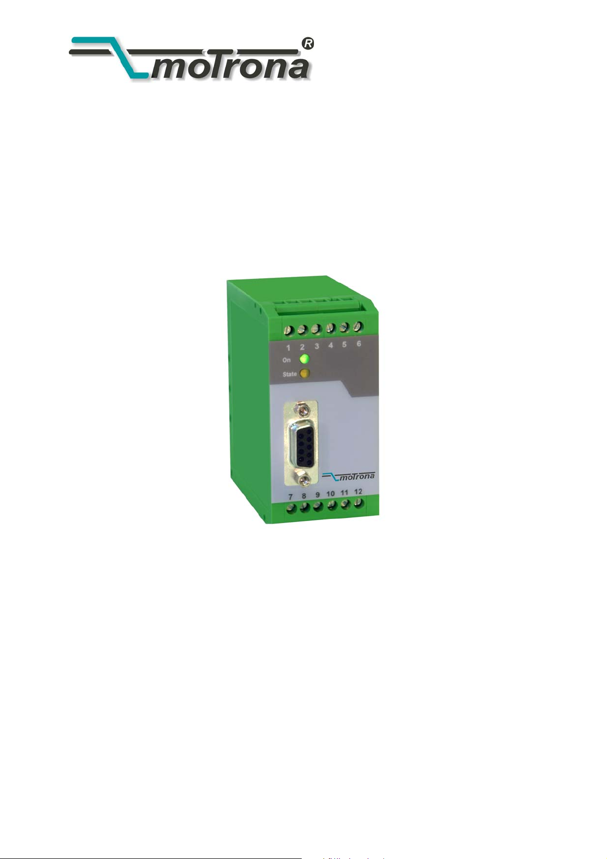
The unit has been designed as a compact module with 12 screw terminals and a 9-position
SUB-D connector (female). The housing is suitable for standard DIN rail mounting.
Applicable encoders and sensors:
Single-turn or multi-turn absolute encoders and all similar sensors using a standard SSI
interface (6 to 25 bits of resolution with binary or Gray code). The unit can operate in either
master mode (clock signal generated by the IV251 unit), or in slave mode (clock signal
generated by a remote device)
Remark to the encoder resolution:
The unit provides settings for the standard resolutions of 13 bits, 21 bits and 25 bits. In
general, for sensors with other resolutions you can use the next higher setting (i.e. set the
unit to 21 bits with a sensor of 16 bits).
Depending on brand and specification of the encoder, in some cases it may be necessary to
blank out the surplus bits by using the bit blanking function described later. In general
however, the unit should work perfectly also without special bit blanking.
IV25101A_e.DOC / Feb-08 Page 4 / 25
Page 5
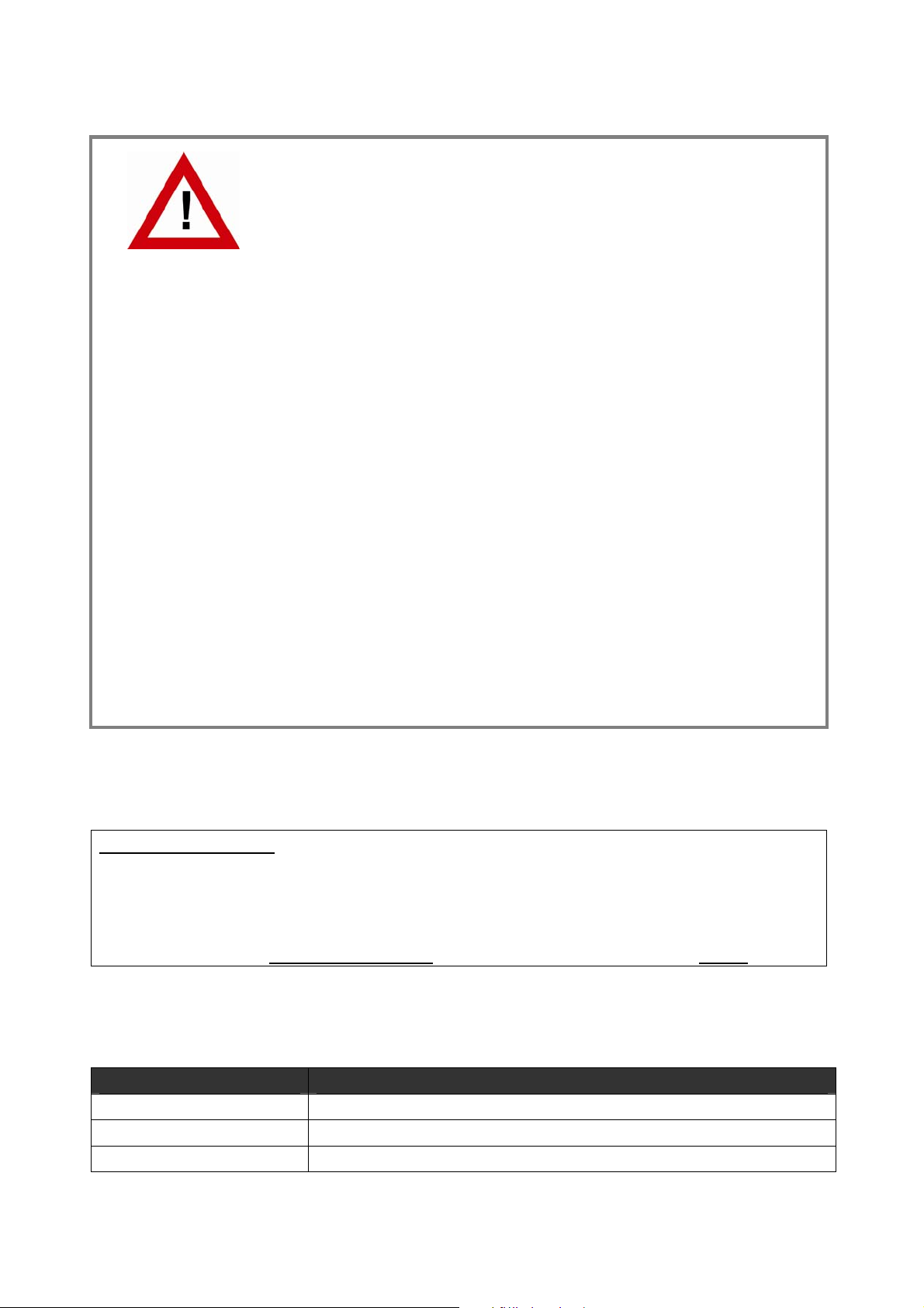
2. Terminal Assignments and Connections
The subsequent diagram shows the assignment of the screw terminals.
We recommend to connect the Minus wire of the power supply to earth potential. GND
terminals 4, 6 and 12 are connected internally. Depending on input voltage and load of the
auxiliary voltage output, the total power consumption of the unit is about 200 mA.
0-20mA / 4-20mA out
Aux. 5.5V ou t (m ax . 150 m A)
SS I D ata (-)
SS I D ata (+)
Set
7
8
9
1
0
1
1
1
2
P
O
W
E
R
1
2
3
4
5
6
Analo gue out +/-10V
SSI- Clock (-)
SSI- Clock (+)
Analogue GND ( - )
+18...30 VD C ( typ. 20 0 m A)
GND ( - )GND ( - )
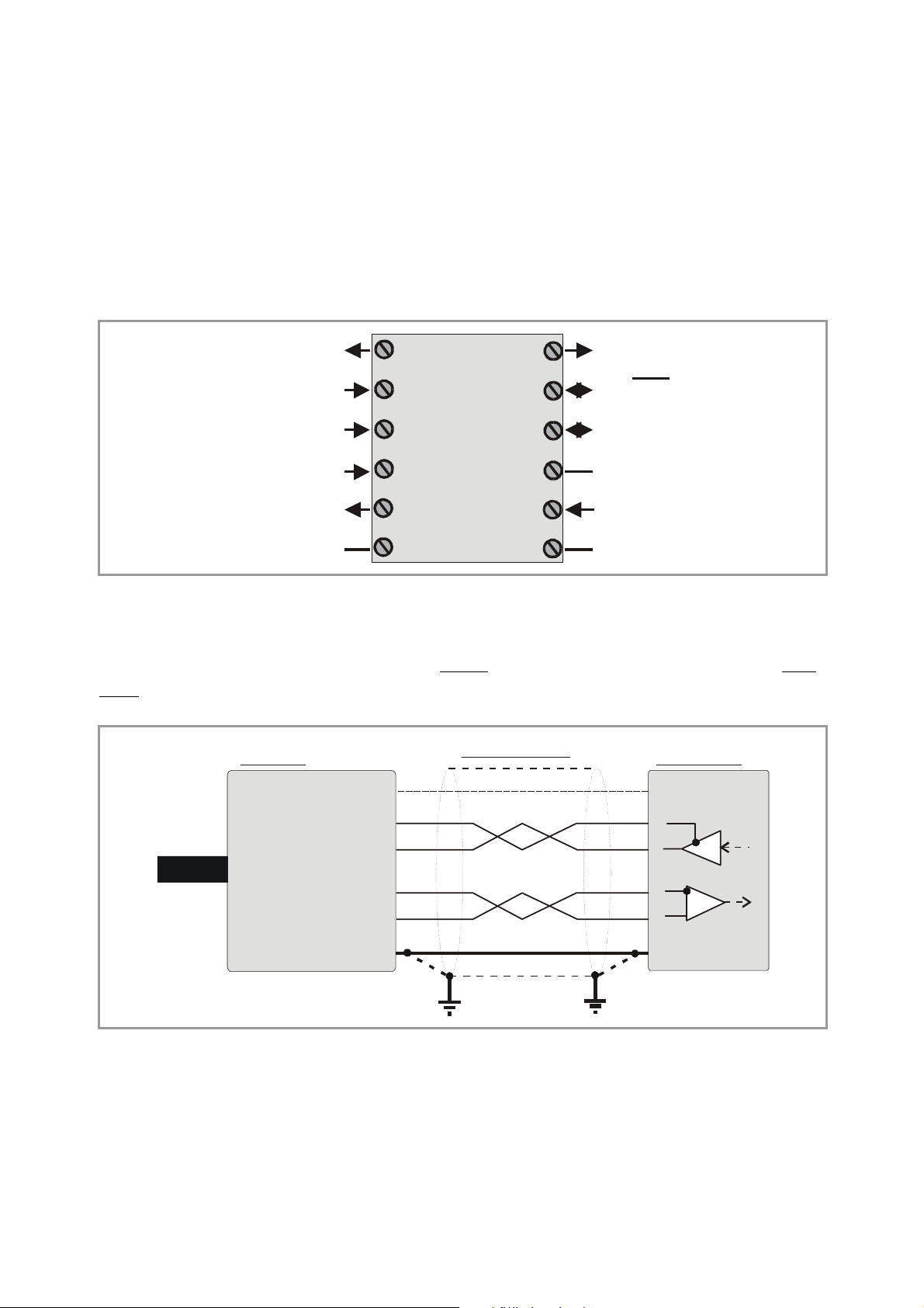
2.1. Encoder connections with Master operation
We recommend to connect the screen to the Minus wire of the encoder supply voltage on both
sides.
SSI encoder
(+5,5V)
Clock-
Clock+
DataData+
GND
Master mode
(optional)
IV251 converter
11 (+5.5V)
2
3
8
9
12 (GND)
IV25101A_e.DOC / Feb-08 Page 5 / 25
Page 6
2.2. Encoder connections with Slave operation
With this mode, the IV251 converter operates in parallel to another unit, acting as a „listener“
to the existing data communication.
Quite according to need, the common potential of the master can be connected to terminal 12
(GND), or remain open for fully differential operation.
Master
Slave mode
ClockClock+
IV251 converter
11 (+5.5V)
2
3
+
-
+
k
k
c
c
o
o
l
l
C
C
+-
Encoder
-
a
a
t
t
a
a
D
D
DataData+
8
9
12 (GND)
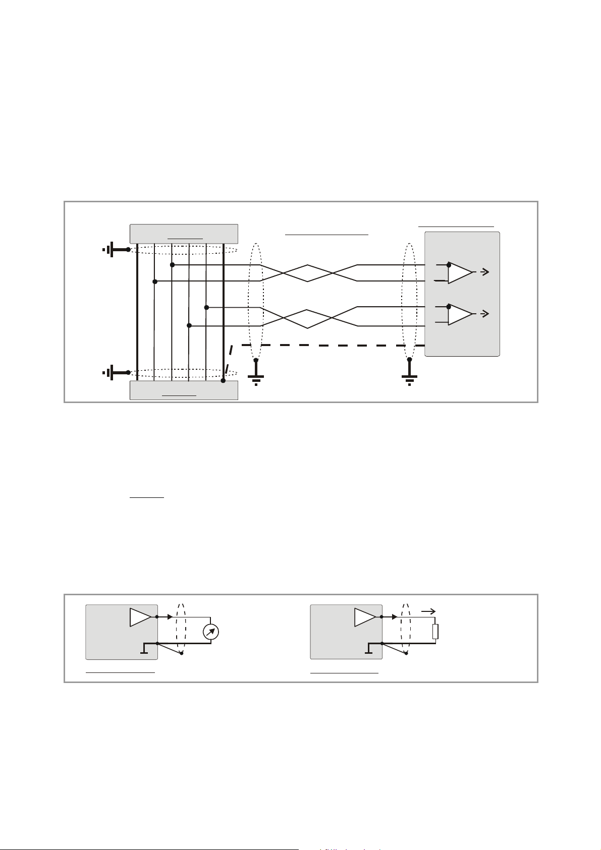
2.3. Analogue outputs
The unit provides one +/-10V voltage output and one 0-20 mA / 4-20 mA current output at a
resolution of 14 Bits
The nominal load of the voltage output is 2 mA; the current output accepts loads between
0 and 270 Ohms.
There is a separate analogue ground terminal, which internally is connected to the GND
potential of the power supply
Vout
GND
(i.e. the voltage output operates in steps of 1.25 mV).
1
4
+/- 10V
(max. 2 mA)
Iout
GND
7
4
0/4 - 20 mA
(R = 0 ... 270 Ohms)
Voltage output
Current output
IV25101A_e.DOC / Feb-08 Page 6 / 25
Page 7
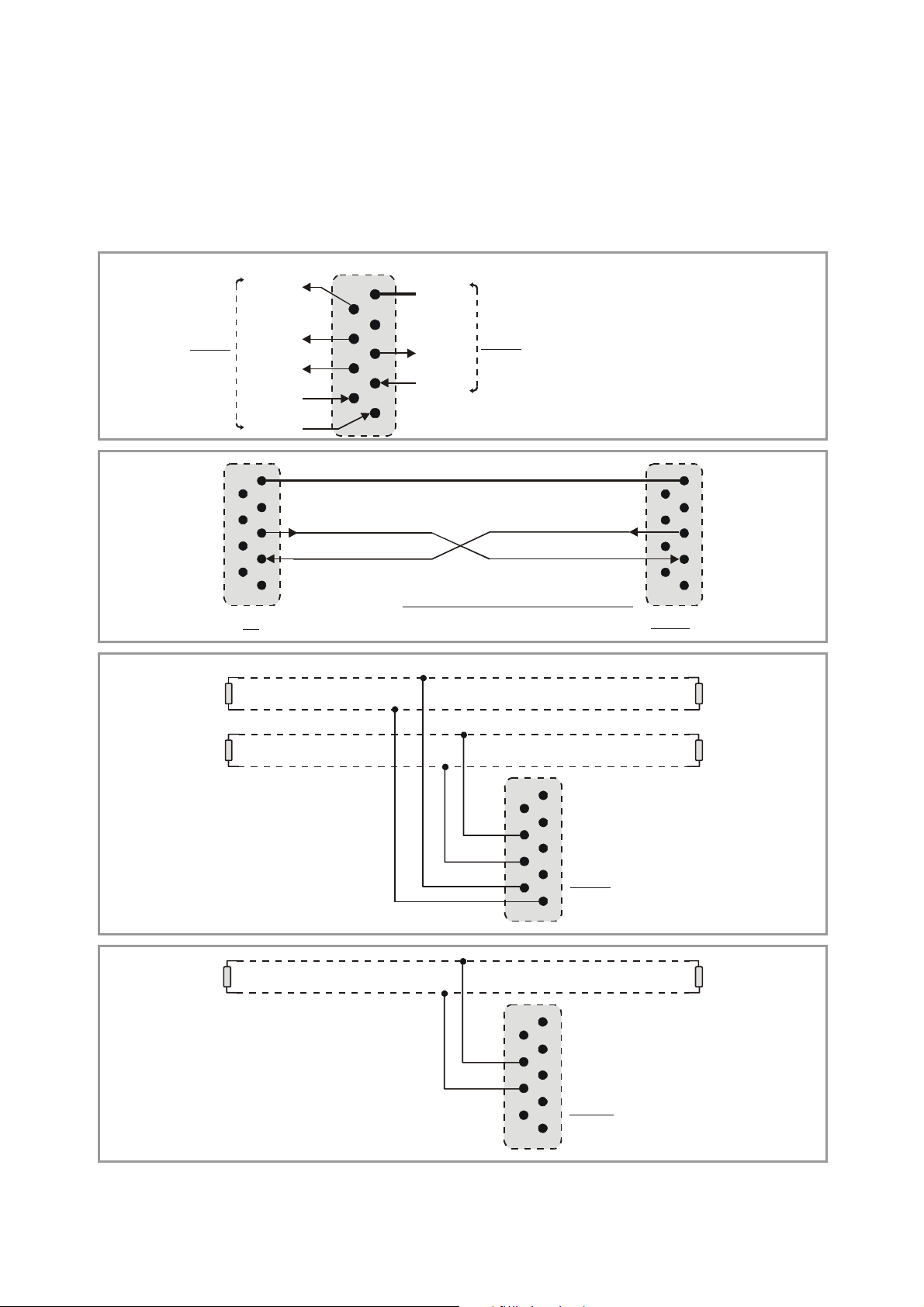
2.4. Serial interface
The unit provides a RS232 interface and a RS485 interface, however only one of the two can be
used at a time. Serial communication allows to read out the encoder position and to set
parameters and variables by PC, according to need.
+5V
5
9
4
RS485
T+
T-
8
3
7
2
R+
6
1
R-
4
4
2
2
GND
TxD
RxD
RS232:
T+
Please connect only pins 2, 3 and 5 !
5
5
9
9
8
8
3
3
7
7
6
6
1
1
PC
GND int.
TxD
RxD
RS232
Sub-D-9 (female on unit site)
5
5
9
9
4
4
8
8
3
3
7
7
2
2
6
6
1
1
IV 251
120 Ohms 120 Ohms
120 Ohms 120 Ohms
RS485- Bus
( 4- wire )
120 Ohms
RS485- Bus
( 2- wire )
TR+
R-
5
5
9
9
4
T+
T-
R+
R-
T+
T-
4
8
8
3
3
7
7
2
2
1
1
IV 251
6
6
120 Ohms
5
5
9
9
4
4
8
8
3
3
7
7
2
2
1
1
IV 251
6
6
IV25101A_e.DOC / Feb-08 Page 7 / 25
Page 8
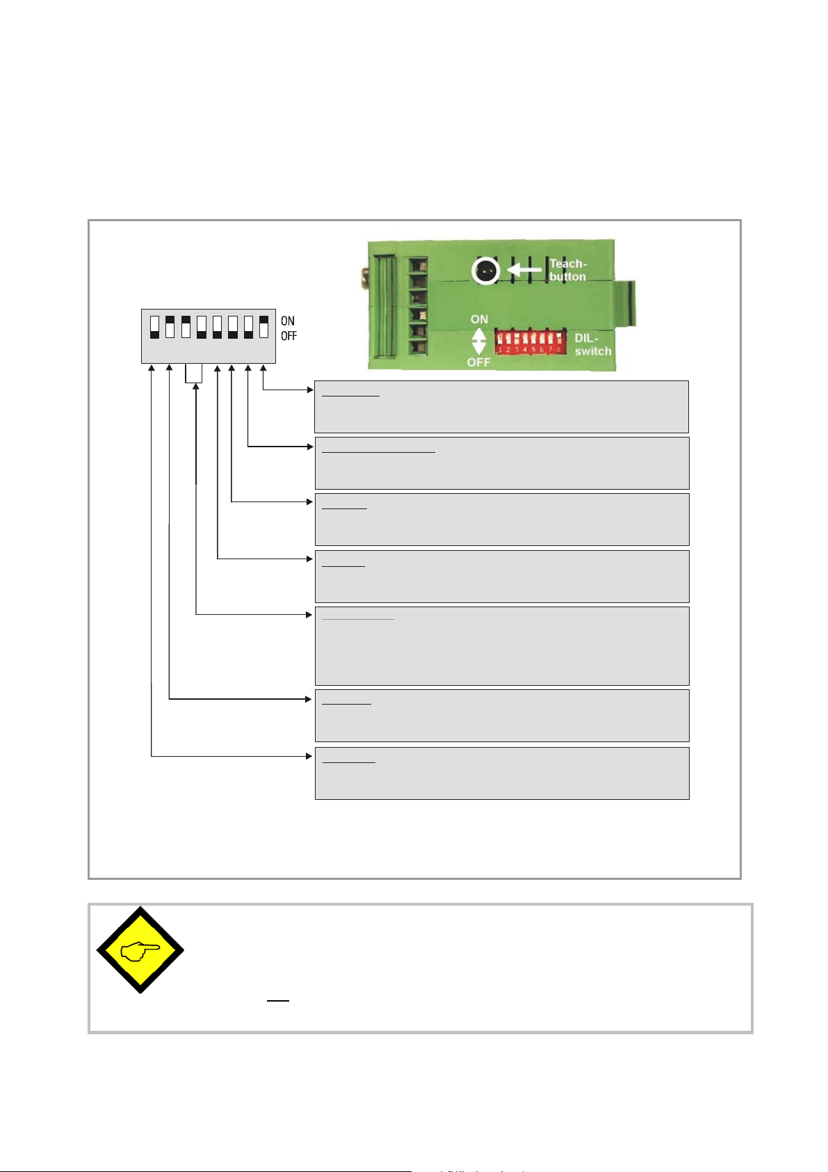
3. DIL switch settings
The DIL switch located on the top site of the unit provides customer-specific settings of desired
operation modes.
1 2345678
Set Default:
OFF:Unit loads default settings with every power-up cycle
ON : No loading of default settings upon power-up.
Analogue Update Mode
OFF:Update of analogue output in a fixed preset time pattern
ON: Update of analogue output after every SSI telegram
SSI- Test:
OFF: Normal LED operation, Teach function enabled
ON: Verifies correct status of clock and data lines, Teach function disabled
SSI Code
OFF: Gray Code
ON: Binary Code
SSI Resolution:
3 OFF, 4 OFF : not valid
3 ON, 4 OFF : 25 Bit
3 OFF, 4 ON : 21 Bit
3 ON, 4 ON : 13 Bit
SSI Mode:
OFF: Slave Mode
ON : Master Mode
Serial Port:
OFF : RS 232- Format
ON : RS 485- Format
The switch settings shown above are suitable for Master operation of a 25 bit SSI encoder with Gray
coded output. The analogue output operates with equidistant update time and the serial link is set to
RS232 communication.
• Changes of the switch settings will become active only after the
next power-up cycle!
• After setup and commissioning, please set DIL switch position 6
to ON
. If set to OFF, any inadvertently touch of the „Teach“ button would
•
overwrite your previous scaling input!
IV25101A_e.DOC / Feb-08 Page 8 / 25
Page 9

4. Commissioning
With basic applications, you can use the Teach procedure for commissioning of the unit.
Extended functions need a PC for setup and are described later.
4.1. Self Test:
Set all DIL switches according to your application and connect encoder and power supply to the
unit. Set switch position No. 6 to ON first (test mode) and power the unit up. The green LED
(power) and the yellow LED (status) must light both. After a successful self-test, the yellow LED
must switch off again (approx. 1 sec.)
4.2. SSI signal test:
Push the Teach button one time now. This will verify the SSI Data lines. The yellow LED must
switch on. Where it remains off, you need to cross the input lines “Data+” (9) and “Data-“ (8).
The second actuation of the Teach button will test the SSI Clock lines in the same manner.
Again, the LED must be lit, otherwise you need to cross the lines “Clock+” (3) and “Clock-“ (2).*)
The third actuation of the Teach button will switch the LED off and conclude the test cycle.
Where you find your status LED lit after the first and the second actuation of the button, your
wiring of the encoder is o.k. Please power the unit down and set DIL position 6 to OFF for Teach
operation. With use of a PC and the OS32 operator software, you can check the status also
from the indicator boxes „Status SSI clock“ and „Status SSI data“ (red = status o.k.)
4.3. Scaling of the analogue output with use of the Teach function:
Power the unit up again, with DIL position 6 set to OFF. Press the Teach button one time.
The status LED will blink in a slow sequence now while the unit waits for the zero position.
Move your encoder to where you like zero output and press the button again.
This stores your zero definition and the LED will blink in a fast sequence now while the unit
waits for the full scale position. Move your encoder to where you desire full scale output and
press the button once more.
This stores your full scale definition and the LED will switch off. Your analogue output is now
set to the desired operating range, as selected by the output mode setting.
*) Testing the clock lines is primarily useful with Slave operation. Though the test works also in Master
mode, the result says only that the internal generation of the clock works fine. However, with Master
mode, this test cannot indicate faulty clock drivers or bad wiring of the clock lines.
IV25101A_e.DOC / Feb-08 Page 9 / 25
Page 10

• Your full scale position is allowed to be higher or lower than the zero position
• More scaling facilities and linearization functions are available with PC setup
• Teach min“ always refers to the initial output value defined by „Output
mode“, i.e. 0 volts or 0 mA or 4 mA
• When, after setting of the full scale position, the status LED does not switch
off, this indicates an overflow error where the mechanical zero position of
your encoder lies between your two teach settings. In this case you need to
change the zero position of the encoder (mechanically or by corresponding
programming of the encoder). With PC setup, the converter itself provides
also an electronic suppression of the overflow jump
• The only way to reset an overflow error state is to cycle the power supply
• The LED overflow check may fail with encoders providing a resolution
lower than 13 bits
Overflow error
Teach min.
Encoder zero
Teach max.
4.4. The Set Input:
With a HIGH signal on the Set input (terminal 10), the unit temporary substitutes the SSI
encoder data by a set value as entered to the “SSI Set Value” register, and the analogue output
as well as the serial readout will follow correspondingly. This means, independent of the actual
mechanical position of the encoder, the unit internally uses the register data instead of the
encoder SSI data. It turns back to normal encoder reading as soon as the Set signal goes LOW
again.
This function can be very useful for testing and commissioning purpose.
The Set input uses PNP / HTL characteristics (LOW = open or 0 – 3 V, HIGH = 10 – 30 V)
IV25101A_e.DOC / Feb-08 Page 10 / 25
Page 11

5. Serial Readout of the Actual Encoder Position
You can read out the actual SSI position of the encoder at any time from the serial link. For
setting of communication parameters, a PC is required.
IV251 uses the DRIVECOM communication standard according to ISO 1745.
Details about this protocol can be found in our file Serpro1a.doc
download on the
The serial access code for the actual encoder position is „ :8
(ASCII characters, colon and 8)
motrona
homepage.
which is available for
„
IV25101A_e.DOC / Feb-08 Page 11 / 25
Page 12

6. PC setup using the operator software OS32
You can apply the full set of functions when using a PC and our operator software OS32 for
setup of the unit. You can download this software and full instructions, free of charge, from our
homepage
www.motrona.de
• Connect your PC to the converter, using a serial RS232 cable like shown in section 2.4 of
this manual. Make sure, the cable only connects pins 2, 3 and 5.
• Run the OS3.x software and you will find the following screen:
• In case your text and color fields remain empty and the headline says „OFFLINE“, you must
verify your serial settings. To do this, select „Comms“ from the menu bar. Ex factory, all
motrona
units use the following serial standard settings:
Unit No. 11, Baud rate 9600, 1 start/ 7 data/ parity even/ 1 stop bit
• If the serial settings of the unit should be unknown, you can run the „SCAN“ function from
the „TOOLS“ menu to find out.
IV25101A_e.DOC / Feb-08 Page 12 / 25
Page 13

7. Parameter Settings
7.1. Display Settings:
X Operand, / Operand, +/-Operand:
These operands serve for conversion of the position information transmitted by the encoder into
other engineering units like millimeters or inches etc. This conversion only refers to the numeric
readout value by serial link, but does not affect the scaling of the analogue output.
With the settings x Operand = 1.0000
/ Operand = 1.0000 and
+/- Operand = 0.0000
the serial readout value equals to the encoder value.
Serial Readout SSI encoder data = x
[
xOperand
]
/Operand
+ +/-Operand
7.2. General Settings:
Teach Minimum, Teach Maximum:
These two settings define the range of the encoder where the analogue output should move
between minimum and maximum output. At any time you can use the Teach button of the unit
or the soft keys on the screen to set these registers*), but you are free to enter your settings
directly by keyboard, without using the Teach function.
Round Loop:
In general, this setting should be 00000. Any other settings will substitute the real encoder
position by a repeating cycle count.
Example
range between 0 and 2047. When we underpass zero with reverse direction, again 2047 will
appear. When we exceed 2047 with forward direction, we restart at 0 again.
The zero position of the round-loop counter can be set by register “SSI-Offset” which allows
settings between 0 and the Round-Loop value. Register “Direction” allows to set the counting
direction of the round loop counter (0 = up, 1 = down).
Within this new definition of a round-loop range, you are free to set the zero and full scale
thresholds of your analogue output again by means of Teach-Min. and Teach-Max. parameters.
*) Click to Teach-Min (on) and again (off), then click to Teach-Max (on) and again (off).
To activate your Teach results, click to “Activate Data”, to read out and see your Teach results on the
screen, click the “Read” key.
All settings will be finally stored to the unit after clicking the “Store EEprom” key.
: when we set this register to 2048, the internal position register will only move in a
IV25101A_e.DOC / Feb-08 Page 13 / 25
Page 14

The following drawings explain the coherence between original encoder data, Round-Loop
setting, SSI-Offset and Direction register.
8192
Original encoder signal
Encoder 13Bit
Direction = 0
SSI-Offset = 1024
Round-Loop = 2048
2048
1024
0 360
Volt
8192
T-Max
T-Min
Round-Loop= 2048SSI-Offset= 1024
Round-Loop signal
180
Analogue Output (Output Mode = 1)
Original encoder signal
degrees
Encoder 13Bit
Direction = 1
SSI-Offset = 1024
Round-Loop = 2048
Round-Loop signal
2048
1024
T-Max
T-Min
0 360
Volt
180
Round-Loop= 2048SSI-Offset= 1024
Analogue Output (Output Mode = 1)
degrees
The Round-Loop function is also suitable to suppress the encoder overflow, when the
mechanical zero position of your encoder lies between your Teach-Min and Teach-Max values
and you do not like to change the mechanical situation. As shown in the subsequent picture,
you need to set the Round-Loop register to the full encoder resolution and then shift the zero
transition by setting the SSI Offset correspondingly.
IV25101A_e.DOC / Feb-08 Page 14 / 25
Page 15

• Every change of the Round-Loop setting requires new entry of Teach-Min,
Teach-Max and Offset values
• With use of the Round-Loop function it is also possible to change the
counting direction of the encoder, by setting the Direction bit correspondingly
• After any action concerning the round-loop and direction settings, new entry
of Teach-Min, Teach-Max and Offset becomes necessary.
8192
Encoder 13Bit
Direction = 0
SSI-Offset = 2048
Round-Loop = 8192
Original encoder signal
T-Min
T-Max
2048
0
Volt
Analogue Output (Output Mode = 1)
Round-Loop signal
360180 degrees
Output Mode:
Selects the output format of the analogue outputs like shown:
V
Min. Max.
Output Mode = 0
-10V ... 0 ... +10V
Encoder
V
Min.
Max.
Output Mode = 1
0 ... +10V
Encoder
mA
Min.
Max.
Output Mode = 2
4 ... 20 mA
Encoder
mA
Min.
Max.
Output Mode = 3
0 ... 20 mA
Encoder
Linearisation Mode:
Sets the mode of linearization
0: Linearisation off, registers P1 to P16 do not affect the output characteristics.
1: Linearisation in a range of 0 – 100%
2: Linearisation over full range –100% to +100%
(See examples under the section „Linearisation”)
IV25101A_e.DOC / Feb-08 Page 15 / 25
Page 16

t
7.3. SSI Specific Settings:
SSI Low Bit:
Defines the lowest bit (LSB) for evaluation, when the bit blanking function is used.
Must be set to “01” for evaluation of the full encoder range.
SSI High Bit:
Defines the highest bit (MSB) for evaluation, when the bit blanking function is used.
Must be set to the total number of encoder bits for evaluation of the full encoder range.
The following example uses a 13 bit encoder where High Bit is set to 12 and Low Bit is set to
03, resulting in evaluation of bits 03 to 12 only and blanking out positions 01, 02 and 13.
High order bit Low order bi
(Hi_bit = 12, Lo_bit = 03)
13 12 11 10 09 08 07 06 05 04 03 02 01
Evaluated encoder bits
(LSB)(MSB)
Hint for the use of the bit blanking function:
Bit blanking results in a different evaluation of the encoder information, and you should be fully
aware of what happens with the resolution and the number of registered turns when you use
this function.
The subsequent example uses a 13-bit single-turn encoder to explain two different results
when blanking out one bit:
• Without blanking, a 13 bit encoder would provide a 0 – 8191 information with a 0 - 360º
turn of the encoder shaft.
This would assume a setting of “High Bit = 13” and “Low Bit = 01”.
It is easy to understand that there are two different ways how to use only 12 of the 13 bits
available:
•
When we set High Bit to 12 while Low Bit remains 01, we have blanked the high order bit.
The result corresponds to an encoder providing information 0 – 4095 while we turn from
0 - 180º, and again the same 0 – 4095 information while we continue from 180º to 360º.
The resolution remains unchanged with respect of the number of steps per revolution.
• We can also leave High Bit to 13 and set Low Bit to 02 instead. This means we blank the
low order bit now. As a result, within one turn of 0 - 360º, we receive the encoder
information 0 – 4095 one time only, but the total number of steps per revolution has been
halved.
IV25101A_e.DOC / Feb-08 Page 16 / 25
Page 17

SSI Baud Rate:
Sets the communication speed of the SSI interface with SSI encoders.
Setting range: 100 Hz to 1MHz.
You are free to set any desired frequency between 0.1 kHz and 1000.0 kHz. For technical
reasons however, in the upper frequency range with Master operation, the unit will only
generate one of the following frequencies accurately:
1 000,0 kHz 888,0 kHz 800,0 kHz 727,0 kHz 666,0 kHz
615,0 kHz 571,0 kHz 533,0 kHz 500,0 kHz 470,0 kHz
444,0 kHz 421,0 kHz 400,0 kHz 380,0 kHz 363,0 kHz
347,0 kHz 333,0 kHz 320,0 kHz 307,0 kHz 296,0 kHz
With Master operation, other settings will result in generation of the next upper or lower value
according to above list. With all settings < 250.0 kHz the error between set rate and generated
rate becomes negligible.
285,0 kHz 275,0 kHz 266,0 kHz 258,0 kHz 250,0 kHz
It is mandatory to set the Baud rate also with Slave operation. In this case, however, the
setting serves only to determine the pause time for correct synchronization (pause is detected
after 4 clock cycles). The unit automatically synchronizes with every remote clock signal within
the specified Baud rate range.
SSI Wait Time:
This register sets the waiting time between two SSI telegrams in a range from 0.001 to 99.999
sec. In normal operation, due to processor cycle times, the real time may vary by 512 μsec. with
respect to the preset time: The fastest sequence possible is 1.3 μsec with a setting of 0.000.
With Slave operation mode, the distance of the SSI protocols depends on the remote Master
and the SSI Wait Time specifies the distance of evaluation data strings. Setting to 100 msec
results in evaluation of one telegram only every 100 msec, even though the Master may have
transmitted many telegrams more.
Especially with applications of closed-loop control loops, it may be of advantage to have
equidistant updating of the analogue output (DIL switch 7 = OFF). This is possible with Master
mode only, and the Wait Time setting (must be >0) directly corresponds to the time pattern of
updates.
The subsequent drawing explains the timing with use of equidistant update mode with a SSI
Wait Time setting of 3 msec.
IV25101A_e.DOC / Feb-08 Page 17 / 25
Page 18

Analogue
Update
Analogue
Update
TM1
SSI-Telegram
0msec
1msec 2msec 3msec
SSI Wait Time = 3 msec
TM2
Auswertung
Calculations
SSI-Telegram
• The shortest possible time for equidistant updating is 1.3 msec, due to
internal processing times (SSI Wait Time set to 0.001)
• The time marks TM1 and TM2 shown in above diagram can be displayed with
the Monitor function of the PC operator software. It is easy to understand
that the sum of both times must be equal to the Wait Time setting; otherwise you must increase the Baud rate or choose a longer update cycle.
(The serial access codes are :3 for TM1 and :5 for TM2)
• In critical cases you can reduce the internal processing times of the unit, by
omitting the conversion of serial RS232 encoder data. For this, just set
parameter “/Operand” to 00000
SSI Offset:
Defines the electrical zero position of the encoder with respect to the mechanical zero position.
When the Round-Loop function is not active (Round-Loop = 0), the SSI Offset is subtracted from
the SSI position reading, which can also cause negative results. When the Round-Loop is
active, SSI Offset displaces the mechanical zero position, but always with only positive results.
SSI Set Value:
Applying a remote Set signal to the Set input (terminal 10) results in a temporary substitution of
the SSI position value by the SSI Set Value entered here. This function allows easy testing and
simulation of fixed analogue output values while commissioning.
IV25101A_e.DOC / Feb-08 Page 18 / 25
Page 19

7.4. SSI Error Settings:
SSI Error Bit:
Defines the position of the error bit, if available with the encoder you use. Errors indicated by
the encoder can be read out via serial code ;9
(semicolon nine, error indication = 2000hex). In
case of an error, on your PC screen, the “Error Bit active” box will appear red and the front LED
will blink at a 1:4 On/Off ratio.
00: no error bit available
13: bit 13 represents the error bit
25: bit 25 represents the error bit etc.
SSI Error Bit Polarity:
Defines the polarity of the Error Bit
0: Bit is LOW in case of error
1: Bit is HIGH in case of error
7.5. Linearisation Settings in %:
P01 (x), P01 (y) etc:
Linearisation registers as shown in section 8.
7.6. Set-up Settings:
Analogue Offset:
This register can adjust the analogue zero output in a range of approx. +/- 100mV
(respectively +/- 200 μA), if necessary.
Analogue Gain:
Sets the maximum output swing of the analogue output.
Setting of 1000 results in a 10 volts respectively 20 milliamps output swing.
Direction:
This parameter changes the internal direction of counting (0 or 1), provided the unit operates in
the Round Loop mode.
Any changes of the Round Loop or Direction registers require a new Teach procedure.
7.7. RS 232 / RS 485 Settings:
Unit Number:
It is necessary to attach a specific address to each unit, since up to 32 units can be connected
to the same bus with RS485 systems. You can choose any address number between 11 and 99.
Factory setting = 11
The address must not contain any “0“ because such numbers are reserved for collective
addressing of several units or groups.
IV25101A_e.DOC / Feb-08 Page 19 / 25
Page 20

Serial Baud Rate:
Setting Baud
0* 9600
1 4800
2 2400
3 1200
4 600
5 19 200
6 38 400
Serial Format:
Setting Data bits Parity Stop bits
0* 7 even 1
1 7 even 2
2 7 odd 1
3 7 odd 2
4 7 none 1
5 7 none 2
6 8 even 1
7 8 odd 1
8 8 none 1
9 8 none 2
* = Factory setting
* = Factory setting
IV25101A_e.DOC / Feb-08 Page 20 / 25
Page 21

8. Free Programmable Linearization
This programmable feature allows the user to convert a linear motion to a non-linear analogue
output and vice-versa. There are 16 programmable interpolation points available, which can be
set in any desired distance over the full conversion range. Between two points, the unit uses
linear interpolation. Therefore it is advisable to use more points in a range with strong curves
and only a few points where the curvature is less.
To specify your desired linearization curve, you must first set the „Linearisation Mode“ register
to either 1 or 2.
Use registers P1(x) to P16(x) to specify the coordinates on the x-axis. These are the analogue
output values that the unit normally would generate according to the actual encoder position.
These settings must be in % of full scale.
Now enter the attached values to registers P1(y) to P16(y). These are the values that the
analogue output will generate instead of the x- values.
As an example, the value of P2(y) will substitute the encoder value P2(x) etc.
*) Output mode = 0
• x-registers must use continuously increasing settings, i.e. P1(x) must have
the lowest setting and P16(x) must have the highest setting
• All entries use a percentage format of xx.xxx% full scale. Setting 0.000%
means zero output and setting 100.000% means full scale output.
• With Linearisation Mode set to 1, it is a must to set P1(x) to 0% and P16(x)
to 100%. Linearization is defined in the positive range only and the negative
range will be a mirror image of the positive range with reference to zero
• With Linearisation Mode set to 2
, it is a must to set P1(x) to –100% and
P16(x) to +100%. This enables the user to set curves which are not
symmetric to the zero position.
y
P1(x)= -100%
P1(y)= 95%
y
P16(x)=100%
P8(y)= 80%
P16(y)= 80%
P8(x)= 0%
x
P1(x)= 0%
*)
Linearisation Mode = 1
P1(y)=10%
Linearisation Mode = 2
x
P16(x)=+100%
P16(y)= -60%
IV25101A_e.DOC / Feb-08 Page 21 / 25
Page 22

You can visualize your curve on the PC screen or by means of an external oscilloscope. For this,
select TOOLS, then TEST and there „Analogue Voltage Function“. The unit will now simulate a
repeating motion of the encoder over the full range and generate the analogue signal
accordingly. When you use the Scope function of the operator software, you must set the serial
code „ :1
„ to record the analogue output.
IV25101A_e.DOC / Feb-08 Page 22 / 25
Page 23

9. Testing Functions
When you select TEST from the TOOLS menu, you are able to verify the following data, by
clicking to the corresponding field:
• Actual encoder position
• DIL switch settings
• Internal supply voltages
• Analogue output state
Furthermore, the following registers can be recorded by using the monitor function:
IV25101A_e.DOC / Feb-08 Page 23 / 25
Page 24

10. Dimensions and Specifications
40 mm
( 1.575’’ )
)
’
’
0
1
1
.
3
(
m
m
9
7
91 mm ( 3.583’’ )
74 mm ( 2.913’’ )
Front view Side view
Top v i ew
Power Supply : 18...30 VDC
Power consumption : about 170 mA at 18V (+5.5V not connected)
about 120 mA at 30V
Inputs (SSI) : TTL differential, RS-422 standard (1.0 MHz)
SSI Format : 13, 21 or 25 Bit (Master / Slave / Gray / Bin)
SSI break time : min. 4 clock cycles
Set Input (HTL) : High > 10V , Low < 3V (Ri = 5k)
Active High; minimum pulse duration 10 msec.
Encoder supply : +5.5V +/- 5% (max. Load: 150 mA)
Analogue outputs : +/- 10V (> 5 kOhm), 0-20 mA / 4-20 mA (<270 Ohms)
Resolution : 14 Bits
Stabilization time : 2 msec.
Accuracy : +/- 0.1%
Temperature-Range : Operation: 0° ... +45°C (+32 … +113°F)
Storage: -25° … +70°C (-13 … +158 °F)
Weight : approx. 190 g
Conformity and Standards : EMC 89/336/EEC: EN 61000-6-2
EN 61000-6-3
LV73/23/EEC: EN 61010-1
IV25101A_e.DOC / Feb-08 Page 24 / 25
Page 25

11. Parameter-List
Parameter Min. value Max. value Default Positions Char. Serial
Code
X Operand -10.0000 +10.0000 1.0000 +/- 6 4 00
/ Operand 0 10.0000 1.0000 6 4 01
+/- Operand -99999999 99999999 0 +/- 8 0 02
Teach Minimum -99999999 +99999999 0 +/- 8 0 03
Teach Maximum -99999999 +99999999 10000 +/- 8 0 04
Round Loop 0 99999999 0 8 0 05
Output Mode 0 3 0 1 0 06
Linearisation Mode 0 2 0 1 0 07
SSI Low Bit 0 25 1 2 0 08
SSI High Bit 1 25 25 2 0 09
SSI Baud rate 100 1000000 100000 7 0 10
SSI Wait Time 0 10.000 0 5 3 11
SSI Offset 0 99999999 0 8 0 12
SSI Reset Value 0 99999999 0 8 0 13
SSI Error Bit 0 25 0 2 0 14
SSI Error Bit Polarity 0 1 0 1 0 15
P1(x) -100.000 +100.000 100000 +/- 6 3 A0
P1(y)….. -100.000 +100.000 100000 +/- 6 3 A1
P16(x) -100.000 +100.000 100000 +/- 6 3 D0
P16(y) -100.000 +100.000 100000 +/- 6 3 D1
Direction 0 1 0 1 0 46
Analog Offset -99 +99 0 +/-2 0 47
Analog Gain 0 10000 1000 5 0 48
Unit Number 0 99 11 2 0 90
Serial Baud Rate 0 6 0 1 0 91
Serial Format 0 9 0 1 0 92
IV25101A_e.DOC / Feb-08 Page 25 / 25
 Loading...