

Page 1
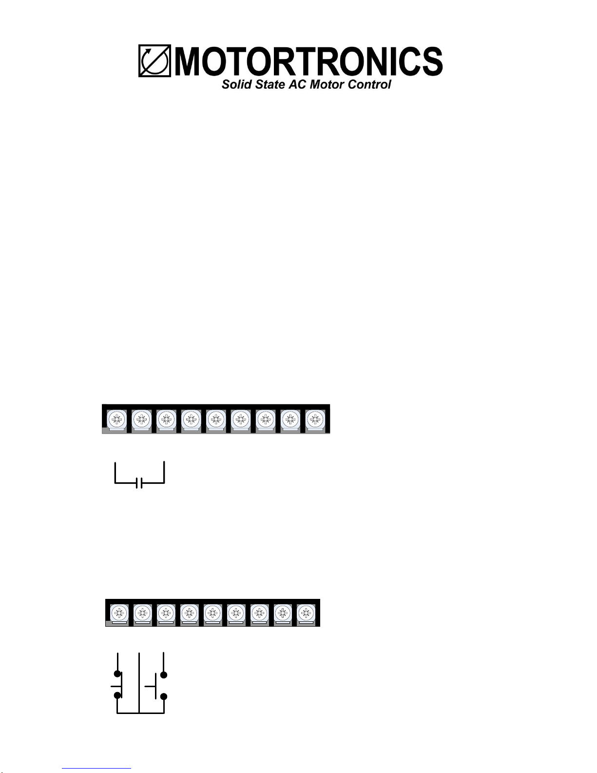
1 2 3 4 5 6 7 8 9
RUN
Customer Terminals TBC on TCB3000 PCB
1 2 3 4 5 6 7 8 9
STOP
START
Customer Terminals TBC on TCB3000 PCB
See page 3.
TCB3000 Terminal Control Board
See page 3.
TCB3000 Terminal Control Board
Manual Addendum for VMX-B Configured Soft Start Packages
For use with wiring diagram # 93-3880 Rev B (CB/FS), or 93-3881 Rev B (MLO), and VMX2 user manual.
Introduction: The VMX-B is a configured enclosed soft start, available as a Combination (with C/B or
Fused disconnect) package, or as an MLO (Main Lug Only) package, intended for use in Industrial,
Commercial, Agricultural, or Infrastructure applications.
Line Voltage:
By default units are set-up for 460VAC line power, but can be adjusted to operate on 230VAC or
208VAC at the reduced HP rating. To adjust the operating voltage simply move wire #1L2B from the
480V (H4) terminal to the 230V (H3) or 208V (H2) terminal.
Power Connections:
Line Power input is connected directly to the bottom terminals of the Circuit Breaker, or line terminals
on MLO (Main Lug Only) units, and the motor is connected to the lugs at the bottom of the VMX2 soft
start.
Remote Start / Stop Control connections:
The VMX-B is set up for 2 or 3 wire remote control using dry contacts rated at 120VAC (0.1Amp).
Remote Two Wire Control:
Connect a dry (voltage free) maintained contact closure between terminals 1 and 3 of the customer
terminal strip as shown here.
Remote Three Wire Control:
For standard 3-wire control, connect dry (voltage free) contacts for the Stop / Start buttons as shown
below of the customer terminal strip. Connect the normally closed “STOP” pushbutton across terminals
1 & 2, and the normally open “START” pushbutton across terminals 2 & 3 of the customer terminal
strip. Note: the unit can be operated in the “Local” position without any external control.
1 REV-02 100418
Page 2
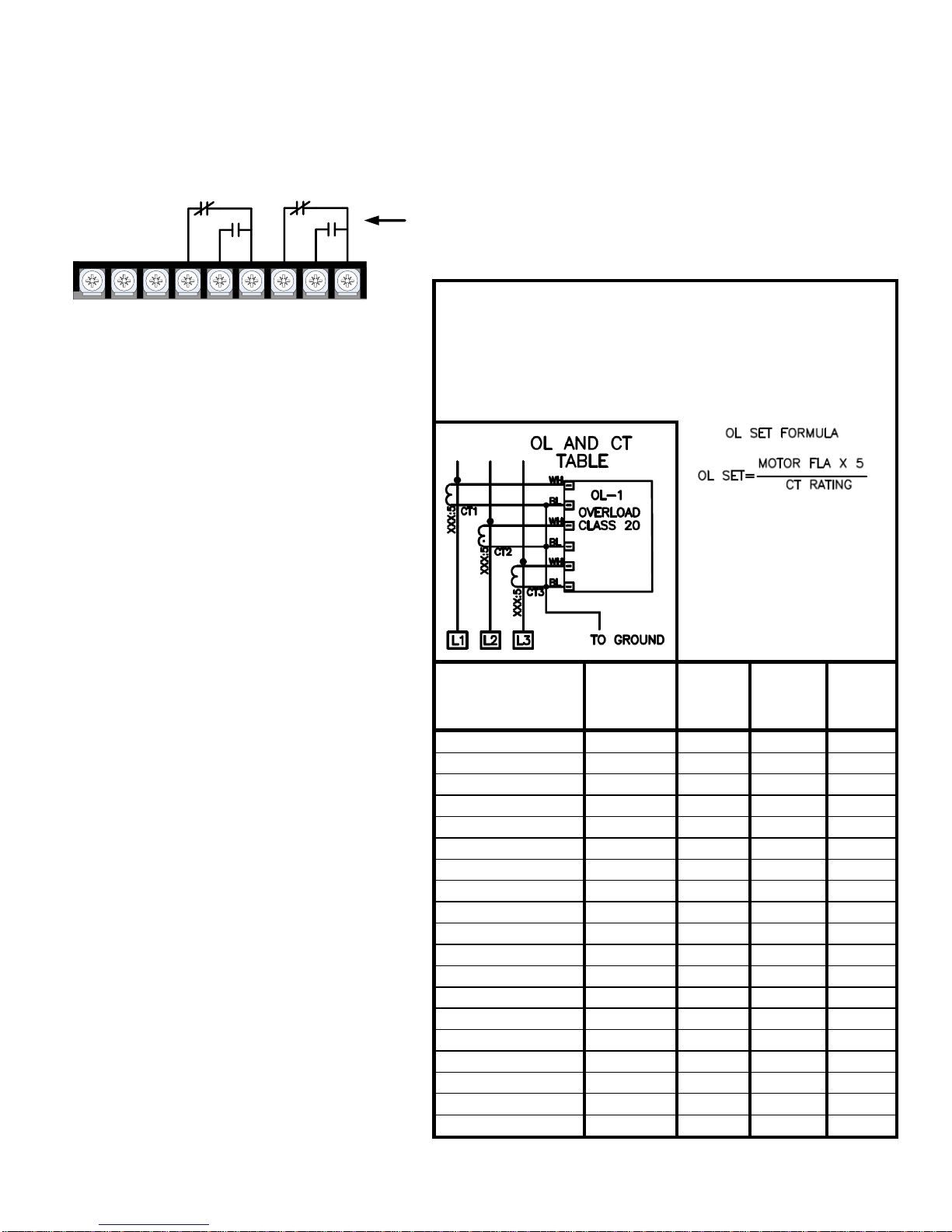
OVERLOAD RELAY OPERATION
WHEN IN HAND (H) POSITION: USER MUST RESET OL
(BY PUSHING GREEN BUTTON)
WHEN IN AUTO (A) POSITION: RELAY WILL
AUTOMATICALLY RESET AFTER TRIPPING
NOTE: YELLOW
OVERLOAD DIAL MUST BE
SET IN ACCORDANCE
WITH THE MOTOR “FULL
LOAD AMPS” PER MOTOR
NAME PLATE DATA
YELLOW OVERLOAD
ADJUSTMENT DIAL
VMX-B
MODEL NUMBER
CT
RATING
XXX:5
4 5 6
VMX-B-21-YY-4
18-25A
18
22
25
VMX-B-27-YY-4
28-40A
28
34
40
VMX-B-40-YY-4
34-50A
34
42
50
VMX-B-45-YY-4
50:5
40
50
60
VMX-B-55-YY-4
75:5
60
75
90
VMX-B-68-YY-4
75:5
60
75
90
VMX-B-96-YY-4
100:5
80
100
120
VMX-B-125-YY-4
120:5
96
120
144
VMX-B-156-YY-4
200:5
160
200
240
VMX-B-220-YY-4
200:5
160
200
240
VMX-B-230-YY-4
250:5
200
250
300
VMX-B-248-YY-4
300:5
240
300
360
VMX-B-400-YY-4
400:5
320
400
480
VMX-B-480-YY-4
500:5
400
500
600
VMX-B-600-YY-4
500:5
400
500
600
VMX-B-690-YY-4
700:5
560
700
840
VMX-B-800-YY-4
700:5
560
700
840
VMX-B-960-YY-4
1000:5
800
1000
1200
VMX-B-1080-YY-4
1200:5
960
1200
N/A
There are 3 programmable Aux contacts
available on TB2 of the VMX2 soft start (2
form-C and 1 form-A). The function of these
contacts are labeled on the wiring diagrams,
but can be changed in the VMX2
programming. Note however, that the
contacts may not function properly when
operating in the X-LINE mode. (see
description below).
X-LINE Operation:
VMX-B packages are supplied with a SOFT/XLINE selector switch, located on the TCB3000
PCB that allows the operator to select Full
Voltage operation of the motor via the bypass
contactor for emergency operation when the
soft start may be inoperable.
When operated in the X-LINE mode full
start/stop control is maintained, and the “Run
Status Output Contacts” will function correctly.
During X-LINE operation, the motor will be
protected by the external Bi-Metal overload
relay which must be set according to the motor
FLA and the Current transformer ratio of the
unit.
Important:
Motor FLA and Service Factor must be
entered prior to a start attempt see next
section on how to set Motor FLA and
Service Factor parameters.
1 2 3 4 5 6 7 8 9
Customer Terminals TBC on TCB3000 PCB
Run Status
Output Contacts
See page 3.
TCB3000 Terminal Control Board
Run Status Output Contacts
The VMX-B unit offers 2 Form-C (N.O and N.C.) “RUN” contacts located on the customer terminal strip, terminals 4
(NC), 5 (NO), 6 (Common), and terminals 7 (NC), 8 (NO) 9 (Common). These contacts reflect a successful RUN
command in “SOFT” or “X-LINE” mode, and should be used for any required “Run / Running” status outputs.
VMX2 Auxiliary Contacts
(TB2 of Soft Starter)
2 REV-02 100418
Page 3
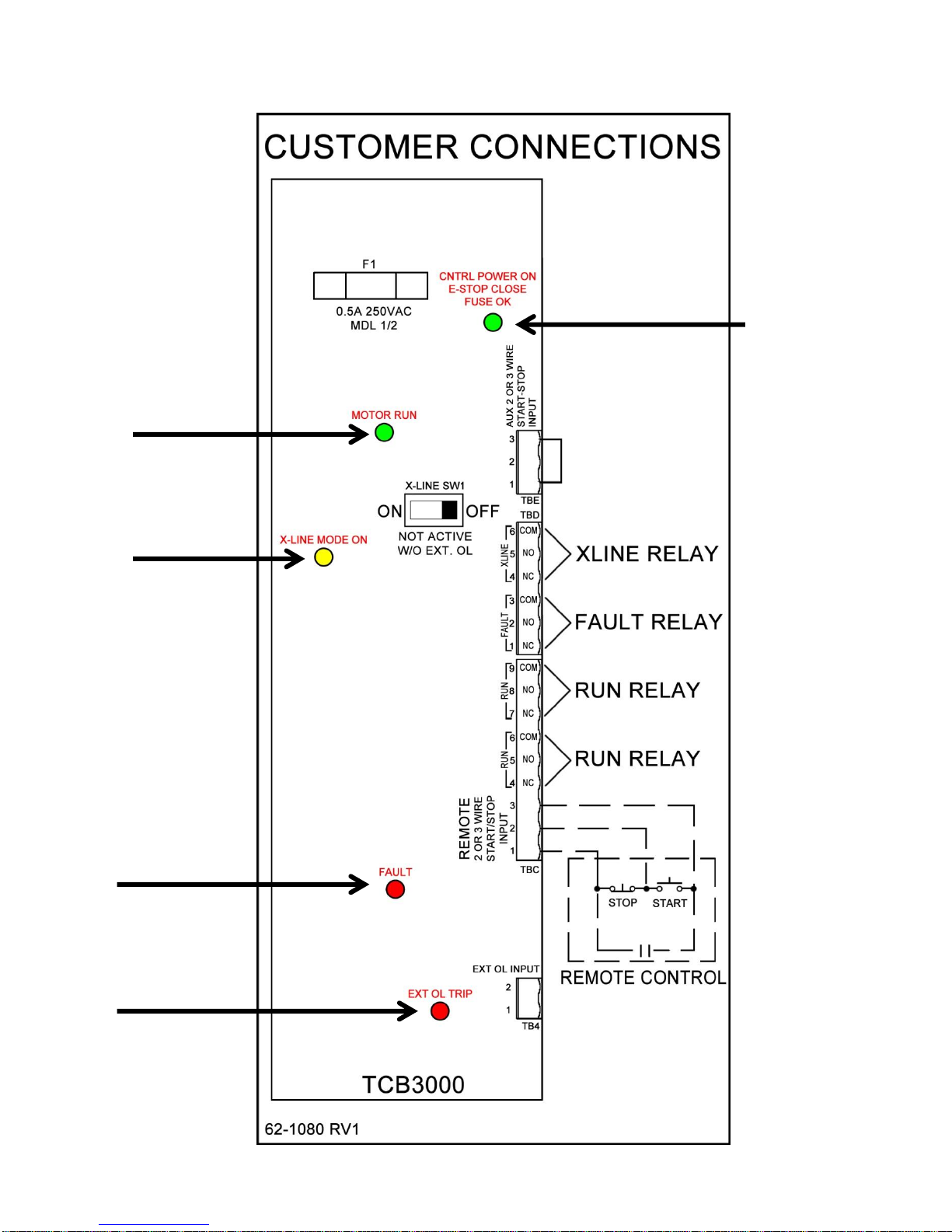
Green LED
- Control Power ON
- E-Stop Not Active
- Fuse OK
Green LED
Motor Running
Yellow LED
X-Line Mode Enabled
(D.O.L. Start)
Red LED
Fault
(Unit Tripped requires
Reset Command)
Red LED
External O/L Tripped
(Reset O/L Manually
by pressing green
button on overload
relay).
TCB3000 Terminal Board
3 REV-02 100418
Page 4
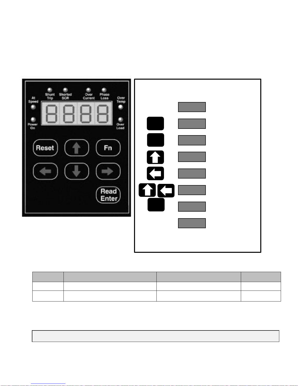
Fn #
Function Description
Range
Default
F001
Motor Nameplate FLA
50-100% of Max Amp Rating.
None
F002
Motor Nameplate Service Factor
1.00 - 1.30 SF
1.0 SF
Means…
Fn
Read
Enter
Press
Key…
0000
F001
0009
0000
0009
0179
End
F001
Default Display
Function #1
Selected
FLA value
(0000 is default)
Set value of ones
digit (flashing)
Set value of
remaining FLA digits
Cursor Position Shift
(tens digit flashing)
Value Accepted
(flashes once)
Use up arrow to scroll to F002 and repeat process
to set Service Factor. When programming is
complete press Fn key to exit programming mode.
Read
Enter
Entering Motor FLA & SF
For Complete Installation instructions see VMX Operation & Installation Manual
Programming Instructions
This document is intended for use with Models: VMX-B Soft Start Packages
Motor FLA and Service Factor must be entered prior to start attempt
For complete parameter list see pages 6-7 of this document
4 REV-02 100418
Page 5
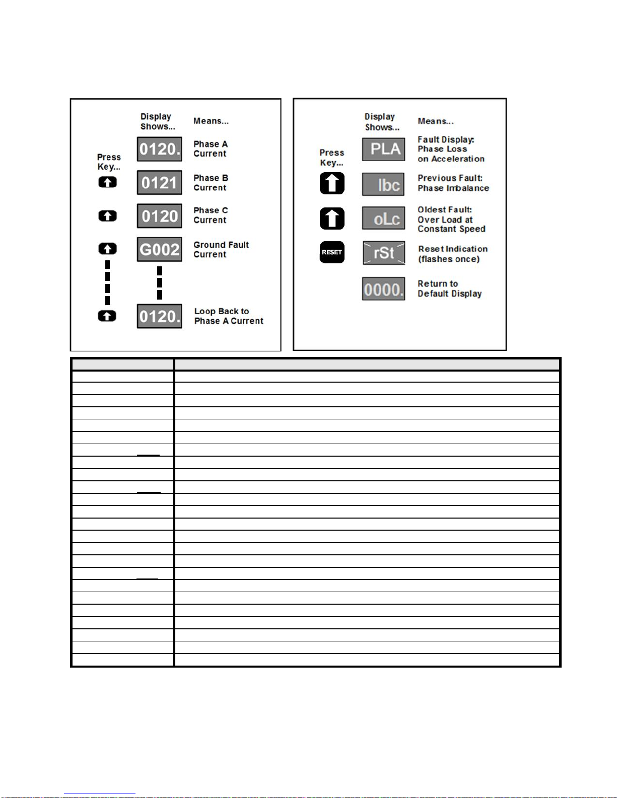
Operation and Troubleshooting
Fault Code
Description
nFLA
No Full Load Amps set in F001
Inh
Parameter change attempted when in Run Mode or without password
N3Ph
Line Voltage Loss (no 3 phase prior to start)
Loc
Lockout Starter is in overload or duty cycle lockout
Err
Incorrect Password Entered
ocA; occ: ocd
Over Current during Acceleration; Constant speed; Deceleration
PLA; PLc; PLd*
Phase Loss during Acceleration; Constant speed; Deceleration
otA; otc; otd
Over Temperature during Acceleration; Constant speed; Deceleration
oLA; oLc; oLd
Over Load during Acceleration; Constant speed; Deceleration
SSA; SSc; SSd*
Shorted SCR during Acceleration; Constant speed; Deceleration
st
Shunt Trip during Acceleration; Constant speed; Deceleration
IbA; Ibc; Ibd
Current Imbalance during Acceleration; Constant speed; Deceleration
UcA; Ucc; Ucd
Under Current during Acceleration; Constant speed; Deceleration
ScA; Scc; Scd
Short Circuit during Acceleration; Constant speed; Deceleration
GFA; GFc; GFd
Ground Fault during Acceleration; Constant speed; Deceleration
bPA; bPc; bPd
Bypass Discrepancy during Acceleration; Constant speed; Deceleration
LcA; Lcc; Lcd*
Normally closed external lockout is open
rtA; rtc; rtd
Rotation Trip during Acceleration; Constant speed; Deceleration
EIA; EIc; EId
Voltage Imbalance during Acceleration; Constant speed; Deceleration
oEA; oEc; oEd
Overvoltage during Acceleration; Constant speed; Deceleration
UEA; UEc; UEd
Undervoltage during Acceleration; Constant speed; Deceleration
PFA; PFc; PFd
Power Factor trip during Acceleration; Constant speed; Deceleration
PrA; Prc; Prd
Power (kW) trip during Acceleration; Constant speed; Deceleration
ncPA; ncPc; ncPd
Control Power Loss during Acceleration; Constant speed; Deceleration
Keypad Operation
Display Mode (Default) Fault Mode
*NOTES:
“PLd” can be caused by a Grounded delta power system. If one input leg measures ZERO volts to ground, reduce
the setting of F051 to “0054” for operation on a “Grounded Delta”.
“SSd” can be caused by operating without a motor connected, ensure the motor is firmly connected.
“LcA, Lcc, or Lcd” indicates that the Surge absorber is damaged; see NOTE 1 on wiring diagram.
5 REV-02 100418
Page 6
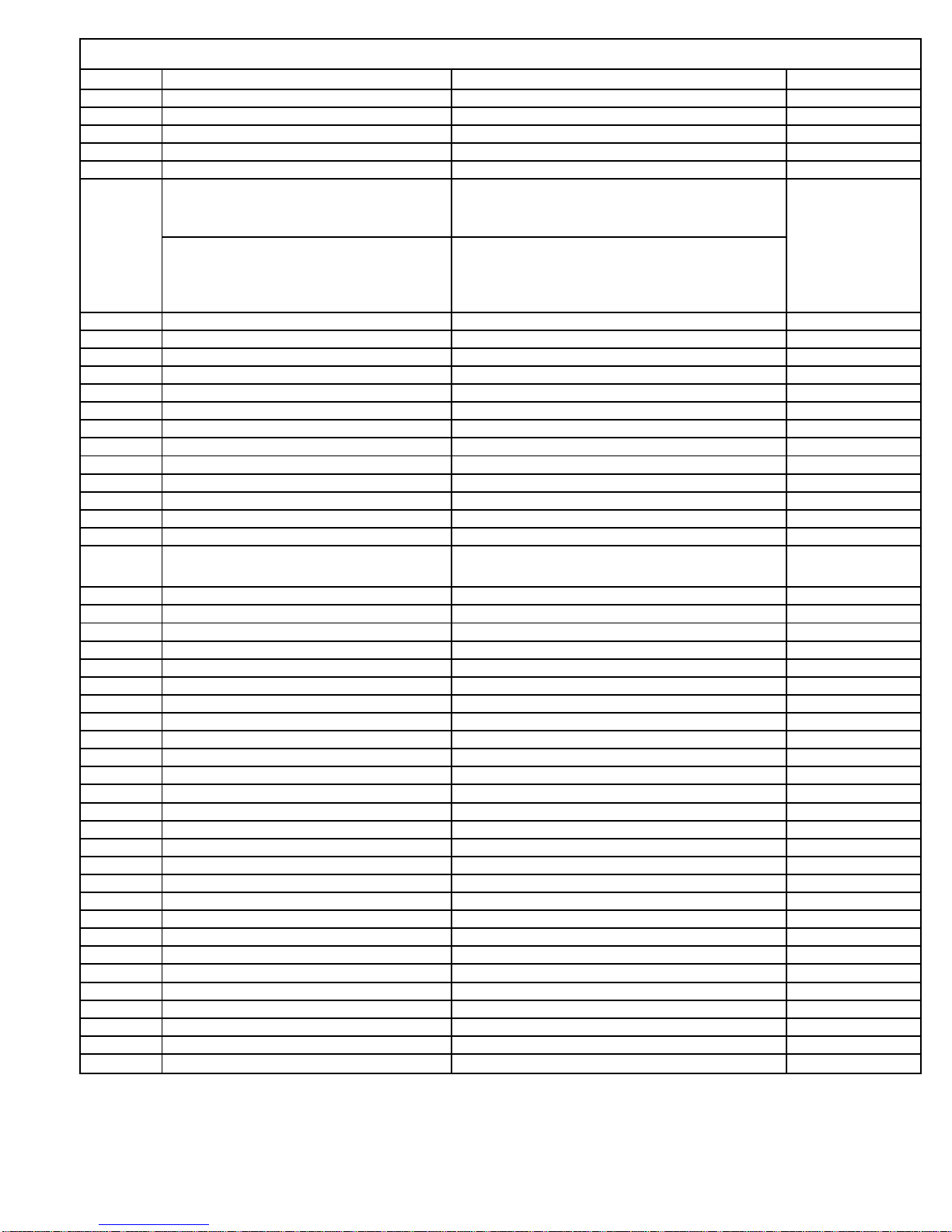
Full Parameter List
Parameter
Description
Adjustment Range
Factory Setting
F001
Motor FLA
50-100% of Max Amp Rating (less Service Factor)
0
F002
Motor Service Factor
1.00-1.30
1.00
F003
Overload Class During Start
NEMA/UL Class 5-30
10
F004
Overload Class During Run
NEMA/UL Class 5-30
10
F005
Overload Reset
0=Manual, 1=Auto, 2=Disabled
0:Manual
F10
Ramp Type (If Ramp 2 is not being used, unit
will ignore all settings referenced to Ramp 2)
Ramp #1 Ramp #2
1
Setting = 1
Setting = 2
Setting = 3
Setting = 4
Voltage Voltage
Current Current
Voltage Current
Current Voltage
F011
Initial Voltage of Ramp 1
0-100% Line Voltage
60%
F012
Initial Current of Ramp 1
0-600% Motor Current
200%
F013
Accel Ramp Time of Ramp 1
1-120 seconds
10 sec
F014
Max Current Limit of Ramp 1
200 - 600% Motor Current
350%
F015
Initial Voltage of Ramp 2 (if Ramp 2 is used)
0-100% Line Voltage
60%
F016
Initial Current of Ramp 2 (if Ramp 2 is used)
0-600% Motor Current
200%
F017
Accel Ramp Time of Ramp 2 (if Ramp 2 is used)
1-120 seconds
10Sec.
F018
Max Current Limit of Ramp 2 (if Ramp 2 is used)
200 - 600% Motor Current
350%
F019
Voltage Jog
5-100% Line Voltage
50%
F020
Time of Voltage Jog
1-20 seconds
10 sec
F021
Current Jog
100-500% Motor Current
150%
F022
Kick Start Voltage
0=Disabled or 10-100% Line Voltage
0
F023
Kick Time
0.1-2 seconds
0.8 sec
F024
Deceleration Ramp (Pump Control)
0=Disabled (Coast to Stop)
1=Enabled (except after OL trip)
0
F025
Begin Decel Level (BDL)
0 - 100 % of Output Voltage
60%
F026
Decel Shut Off Voltage
0 to (BDL minus 1)% Voltage
30%
F027
Decel Ramp Time
1-60 seconds
10Sec.
F028
Auto Restart Delay Time
0=Disabled or 1-999sec after Power Loss
0
F029
Voltage Input
200 - 690 Volt
480
F030
Voltage Imbalance Trip %
0, 1 - 30% [0=Disabled]
0
F031
Voltage Imbalance Trip Delay
1 - 20 seconds
10
F032
Over Voltage Trip %
0, 1 - 10% [0=Disabled]
0
F033
Over Voltage Trip Delay
1 - 20 seconds
10
F034
Under Voltage Trip on Start %
0, 1 - 20% [0=Disabled]
0
F035
UV Trip on Start Delay
1 - 180 seconds
10
F036
Under Voltage Trip on Run %
0, 1 - 20% [0=Disabled]
0
F037
UV Trip Delay during Run
1 - 20 seconds
2
F038
Shorted SCR and Trip Delay
0, 1-10 seconds [0=Disabled]
1Sec
F039
Shunt Trip Delay
0, 1-10 seconds [0=Disabled]
1Sec
F040
Current Imbalance Trip %
0=Disabled or 5-30% imbalance
0
F041
Current Imbalance Trip Delay
1-20 seconds
2 sec
F042
Over Current Trip %
0=Disabled or 100-300% of Motor FLA
0
F043
Over Current Trip Delay
1-20 seconds
1 sec
F044
Under Current %
0=Disabled or 10-90% of Motor FLA
0
F045
Under Current Trip Delay
1-60 seconds
2 sec
F046
Ground Fault Current Trip Value
0=Disabled or 5-90% of CT ratio from Fn74
0
F047
Ground Fault Current Trip Delay
1-60 seconds
2 sec
F048
Coast Down Lockout Time
0=Disabled or 1-60 minutes
0
F049
Maximum Starts per Hour
0=Disabled or 1-10 Starts
0
F050
Minimum Time Between Starts
0=Disabled or 1-60 minutes
0
F051
nCP Trip (No Control Power)
0, 1 [0=Disabled, 1=Enabled]
1
6 REV-02 100418
Page 7
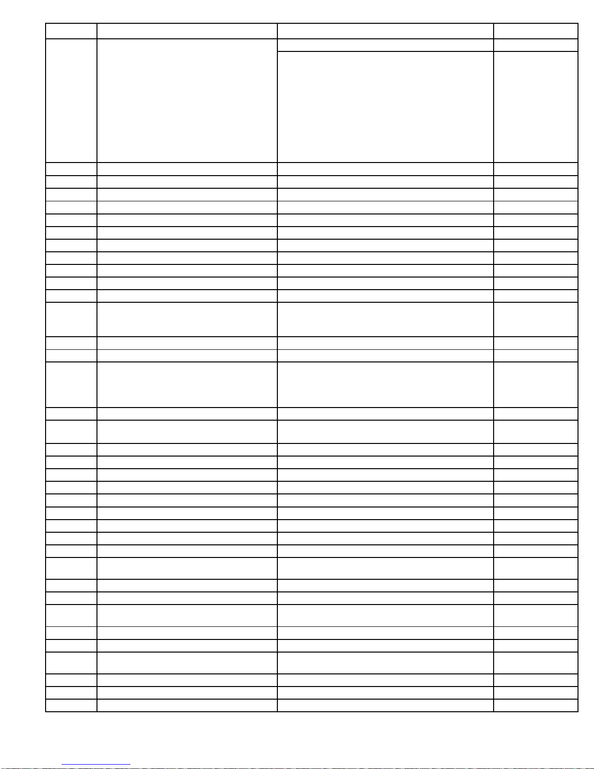
Parameter
Description
Adjustment Range
Factory Setting
F052
Auto Reset Selected Trips
Auto Reset Disabled
0
Reset after Over Temperature Trip only
Reset after Over Current (Shear Pin) Trip only
Reset after Under Current Trip only
Reset after Phase Loss Trip only
Reset after Current Unbalance Trip only
Reset after Ground Fault Trip only
Reset after Short Circuit Trip only
Reset after OT Trip or Over/Under Current Trip
Reset after Phase Loss, Current Unbal, or GF Trip Reset after
all Except Short Circuit Trip
Reset after all Except GF or Short Circuit Trip
Reset after any Trip
1
2
3
4 (Default)
5
6
7
8
9
10
11
12
F053
Auto Restart Attempts
0=Disabled, 1-10 = # of Attempts
0
F054
Auto Restart Delay Readout
Readout only
F055
Coast Down Lockout Time Readout
Readout only
F056
Starts Per Hour Timer Readout
Readout only
F057
Starts Per Hour Readout
Readout only
F058
Time Value Between Starts Readout
Readout only
F059
Thermal Capacity to Start Readout
Readout only
F060
Aux Relay 1 setting
Run/Stop
1
F061
Aux Relay 2 setting
At Speed/Stop
2
F062
Aux Relay 3 setting
Any Trip
22
F063
Aux. Relay Delay Timer
0=Disabled or 1-999 seconds
0
F065
Communications
0=Disabled
1=Enabled(11bit)
2=Enabled(10 bit)
0:Disabled
F066
Baud Rate
4.8, 9.6, 19.2 KB
9.6
F067
Modbus Address
1-247
1
F068
Remote Starter Control from Communications
0=Disabled
1=Enabled w/Start PB
2=Enabled w/o Start PB
3=Enabled via Remote Jog Input
0
F070
Parameter Lock/ Level 1 Password
0=Disabled or 001-999
0
F071
System Clear / Factory Reset
0=Disabled, 1=Clear Lockouts
2=Reset to Factory Default
0
F073
Frame Rating
10-2000A
by model
F074
CT Value
10-2000
by model
F075
Year
2000-2047
2000
F076
Month
1-12
1
F077
Day
1-31
1
F078
Hour
0-23
0
F079
Minute
0-59
0
F080
Seconds
0-59
0
F081
Software rev # (info purposes only)
rev #
Rev #
F085
Fault History #1 (most recent fault code)
0=No Fault History, or Fault # 1-27
(full manual for fault code descriptions)
0
F086
Time Stamp Fault #1
00.00-23.59 (hh.mm)
00.00
F087
Date Stamp Fault #1
01.01-12.31 (MM-DD)
01.01
F088
Fault History #2 (previous fault code)
0=No Fault History, or Fault # 1-27
(full manual for fault code descriptions)
0
F089
Time Stamp Fault #2
00.00-23.59 (hh.mm)
00.00
F090
Date Stamp Fault #2
01.01-12.31 (MM-DD)
01.01
F091
Fault History #3 (oldest fault code)
0=No Fault History, or Fault # 1-27
(full manual for fault code descriptions)
0
F092
Time Stamp Fault #3
00.00-23.59 (hh.mm)
00.00
F093
Date Stamp Fault #3
01.01-12.31 (MM-DD)
01.01
F094
Run Time Hours
000.9-999.9 hours
0000
7 REV-02 100418
Page 8
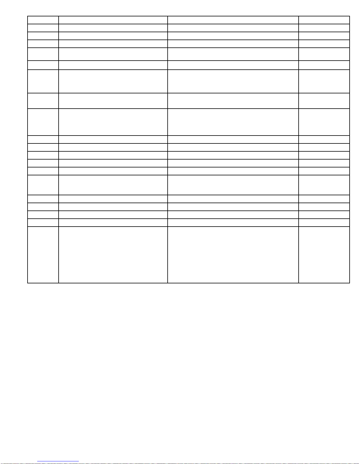
Parameter
Description
Adjustment Range
Factory Setting
F095
Run Time in 1,000s of hours
0000-9999K hours
0000
F096
Run Counts
0000-9999
000
F097
Run Counts in 10,000s of counts
0000-9999 (0001 would equal 10,000 counts)
000
F098
Phase Rotation Trip
0, 1 or 2
0=Disabled, 1=ABC, 2=ACB]
0
F099
Phase Rotation Trip Delay
1 - 3 seconds
1 Sec
F100
Phase Loss Trip Delay during Stop
0 - 20 seconds
[0 = Disabled]
1 Sec
F101
Phase Loss Trip Delay during Running
0 - 20 seconds
[0 = Disabled]
1 Sec
F102
Motor kW Trip
0 - 2
0 = Disabled
1 = Over kW Trip
2 = Under kW Trip
0
F103
Motor kW Trip Point
20 - 100% of full load KW
50(%)
F104
Motor kW Trip Delay Time
1 - 999 seconds
1
F105
Power Factor Trip Range
0, 1 - 3 [0=Disabled, 1=lag, 2=lead, 3= lead/lag]
0
F106
Power Factor Trip Point
.01 - 1
.50
F107
Power Factor Trip Delay Time
1 - 20 seconds
2 Sec
F108
Analog Output
0 - 12
[0: OFF; 1 - 12]
(See Table of Default Display)
OFF
F109
Analog Output 4mA
0 - 9999
0
F110
Analog Output 20mA
0 - 9999
9999
F111
Default Display
1-12 (See Table of Default Display)
10
F112
System Settings
Reserved for factory use
-
F113
Alternate functions for Ramp2/Jog inputs
Setting Dual Ramp Input Jog Input
0 Dual Ramp Jog
1 Dual Ramp Remote / Local
2 Dual Ramp Ext. Lockout N/O button
3 Dual Ramp Ext. Lockout N/C button
4 RESET Jog
5 RESET Remote / Local
6 RESET Ext. Lockout N/O button
7 RESET Ext. Lockout N/C button
7
8 REV-02 100418
Page 9
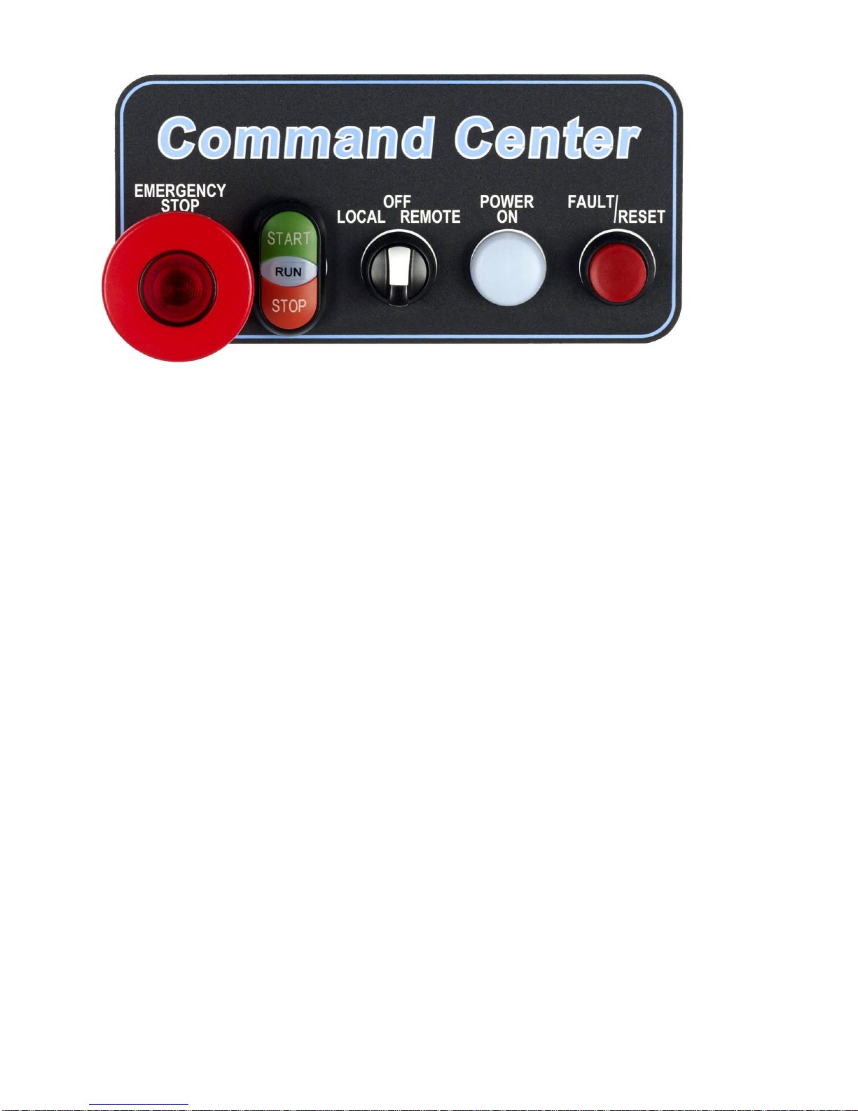
VMX-B Door Mounted Operators
Illuminated E-Stop Pushbutton:
Removes control power from all circuits and VMX2 soft start.
Push to activate, twist and pull to release.
Button Lights when E-stop is pressed.
Start/Stop Pushbutton and Run Light Assembly:
Provides Start/Stop control in "Local" mode.
Provides "Motor Running" indication in all operating modes.
Local/Off/Remote Selector:
Local" selects door mounted Start/Stop control.
Remote" selects Start/Stop control from customer supplied signals at terminals 1-3 on TBC.
Off' Turns motor off.
Power ON Light:
Indicates presence of 120VAC control power, derived from main (L1 & L2) line voltages.
Fault Light/Reset Pushbutton:
When lit, indicates that the unit has tripped, and requires "Reset".
In "Soft" (normal) mode, the "trip" will be displayed on the VMX2 keypad (inside), and will reset
upon activation of the reset pushbutton.
In "X-Iine" mode, the light indicates that the X-line overload inside the panel is tripped, and must be
reset manually by pressing the (green) reset key on the overload itself. Then the unit can be reset,
using the pushbutton on the door.
Note: If the green reset key on the X-line overload is turned to the "A" (auto) position, the O/L relay will
reset itself after the required cooldown, after that the unit can be reset by pushing the reset pushbutton
without opening the enclosure door.
9 REV-02 100418
Page 10
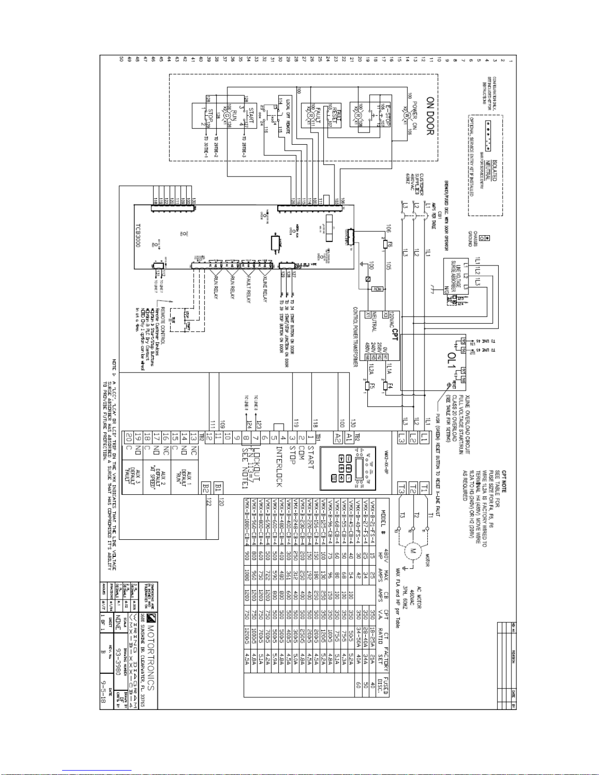
Wiring Diagram # 93-3980
10 REV-02 100418
Page 11
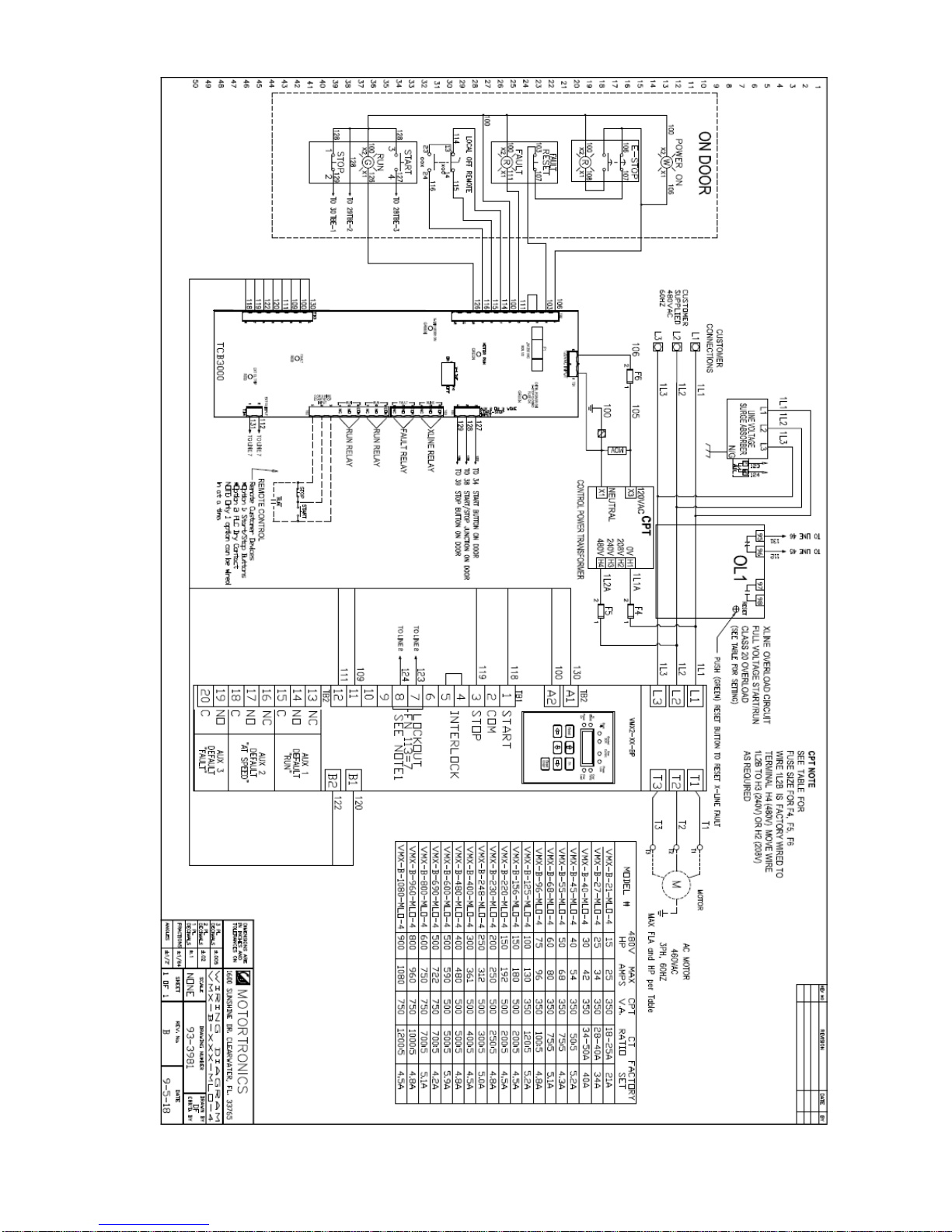
Wiring Diagram # 93-3981
11 REV-02 100418
 Loading...