

Page 1

CTi Automation - Phone: 800.894.0412 - Fax: 208.368.0415 - Web: www.ctiautomation.net - Email: info@ctiautomation.net
MT Series
Installation manual
Retain for future use
Variable speed drives
for AC motors
75 HP (55 kW) ... 100 HP (75 kW) / 200 - 240V
125 HP (90 kW) ... 400 HP (250 kW) / 380 - 480V
Page 2

Content
s
CTi Automation - Phone: 800.894.0412 - Fax: 208.368.0415 - Web: www.ctiautomation.net - Email: info@ctiautomation.net
Contents____________________________________________________________________________________________________ 3
Before you begin______________________________________________________________________________________________ 4
Steps for setting up the drive ____________________________________________________________________________________ 5
Preliminary recommendations ___________________________________________________________________________________ 6
Drive ratings _________________________________________________________________________________________________ 8
Dimensions and weights_______________________________________________________________________________________ 10
Installing the DC choke________________________________________________________________________________________ 12
Connecting the DC choke______________________________________________________________________________________ 13
Derating as a function of temperature and switching frequency_________________________________________________________ 14
Mounting in a wall-mounted or floor-standing enclosure ______________________________________________________________ 16
Installing the kit for IP31/NEMA type 1 conformity ___________________________________________________________________ 19
Position of the charging LED ___________________________________________________________________________________ 21
Installing option cards_________________________________________________________________________________________ 22
Wiring recommendations ______________________________________________________________________________________ 24
Power terminals _____________________________________________________________________________________________ 26
Control terminals_____________________________________________________________________________________________ 38
Option terminals _____________________________________________________________________________________________ 40
Connection diagrams _____________ ____________________________________________________________________________ 45
Operation on an IT system_____________________________________________________________________________________ 58
Electromagnetic compatibility, wiring _____________________________________________________________________________ 61
3
Page 3

Bef
ore you begin
CTi Automation - Phone: 800.894.0412 - Fax: 208.368.0415 - Web: www.ctiautomation.net - Email: info@ctiautomation.net
Read and understand these instructions before performing any procedure on this drive.
HAZARDOUS VOLTAGE
• Read and understand this manual before installing or operating the MT Series driv e.
Installation, adjustment, repair and maintenance must be performed by qualified
personnel.
• The user is responsible for compliance with all international and national electrical
standards in force concerning protective grounding of al l equipment.
• Many parts of this variable speed drive, including the printed circuit boards, operate
at the line voltage. DO NOT TOUCH.
Use only electrically insulated tools.
• DO NOT touch unshielded components or terminal strip screw connections with
voltage present.
• DO NOT short across terminals PA/+ and PC/- or across the DC bus capacitors.
• Install and close all the covers before applying power or starting and st opping the
drive.
• Before servicing the variable speed drive:
- Disconnect all power.
- Place a “DO NOT TURN ON” label on the variable speed drive disconnect.
- Lock the disconnect in the open position.
• Disconnect all power including external control power that may be present before
servicing the drive. Wait for the charging LED to go off. Then follow the DC bus voltage
measurement procedure given on page 21
45 V. The drive LEDs are not accurate indicators of the absence of DC bus voltage.
Electric shock will result in death or serious injury.
DANGER
to verify that the DC voltage is less than
CAUTION
IMPROPER DRIVE OPERATION
• If the drive is not turned on for a long period, the performance of its electrol ytic
capacitors will be reduced.
• If it is stopped for a prolonged period, turn the drive on every two years for at least
5 hours to restore the performance of the capacitors, then check its operation. It is
recommended that the drive is not connected directly to the line vo ltage. The vol tage
should be increased gradually using an adjustable AC source.
Failure to follow these instructions can result in equipment damage.
4
Page 4
Steps for setting up the drive
CTi Automation - Phone: 800.894.0412 - Fax: 208.368.0415 - Web: www.ctiautomation.net - Email: info@ctiautomation.net
INSTALLATION
b 1 Take delivery of the drive
v Check that the catalog number printed on the label is the same
as that on the purchase order
v Remove the MT Series from its packaging and check that it has
not been damaged in transit
b 2 Check the line voltage
v Check that the line voltage is compatible with the
voltage range of the drive (see pages 8 and 9)
Steps 1 to 4 must
be performed with
the power off
b 3 Mount the drive
v Mount the drive in accordance with the instructions
in this document
v Install and connect the DC choke (see page 11)
v Install any internal and external options
b 4 Wire the drive
v Connect the motor, ensuring that its
connections correspond to the voltage
v Connect the line supply, after making sure that
it is turned off
v Connect the control
v Connect the speed reference
PROGRAMMING
v 1 Please refer to the
Programming Manual
5
Page 5
Prelimi
MT
CTi Automation - Phone: 800.894.0412 - Fax: 208.368.0415 - Web: www.ctiautomation.net - Email: info@ctiautomation.net
Figure 1
nary recommendations
Receiving
DC choke
The packaging contains two items:
- The drive
-A DC choke (figure 1)
Handling/storage
To protect the drive prior to installation, handle and store the device in its packaging.
Ensure that the ambient conditions are acceptable.
WARNING
DAMAGED PACKAGING
If the packaging appears damaged, it can be dangerous to open and handle it.
Take precautions against all risks when performing this operation.
Failure to follow these instructions can result in death or serious injury.
WARNING
Figure 2
60°
max.
Figure 3
DAMAGED EQUIPMENT
Do not install or operate any drive that appears damaged.
Failure to follow this instruction can resu lt in dea th or se rio us inj ury .
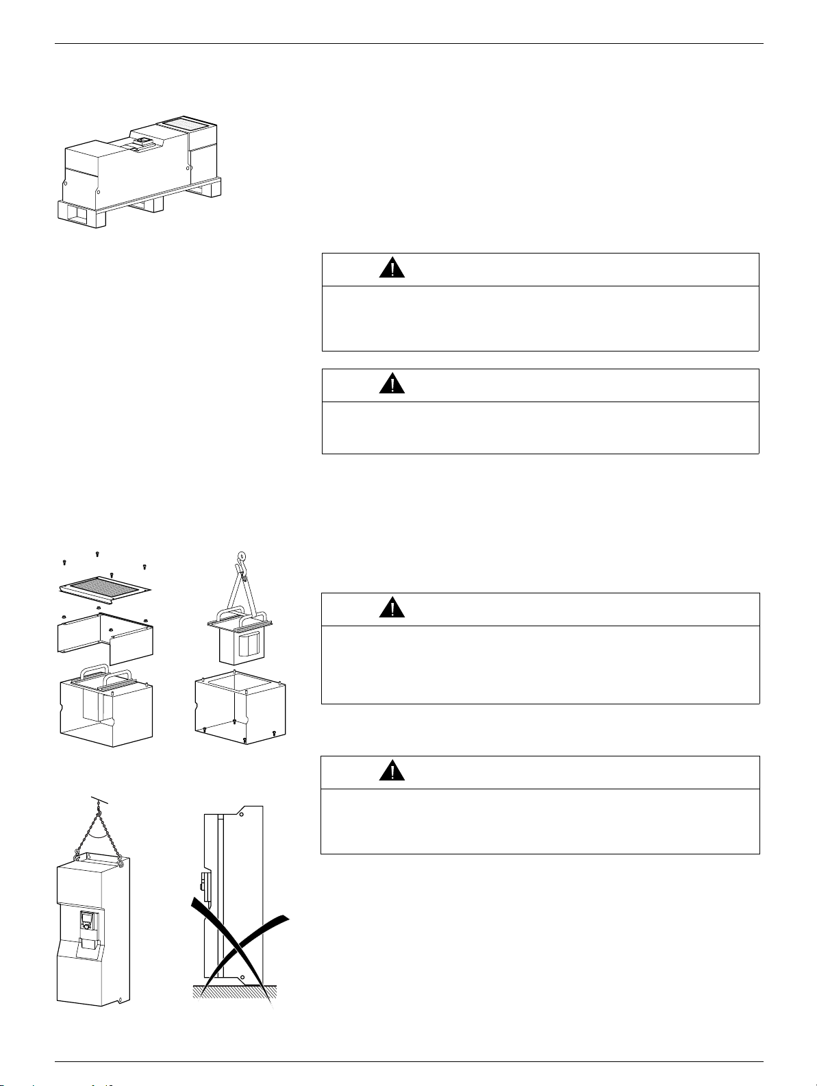
Unpacking/handling
The drive and DC choke (if applicable) are attac hed to a palle t usi ng screws (figure 1).
When there is a DC choke, it is supplied assembled for ease of transport.
The equipment must be unpacked in the following order:
Dismantle the DC choke (figure 2) so that it can subsequently be installed,
1
and remove the choke using a hoi
Remove the screws attaching the choke support to the pallet (figure 3).
2
st (figure 3).
WARNING
RISK OF INJURY
The screws used to attach the choke support to the pallet are difficult to access,
involving a risk of injury. Take every precaution to avoid this risk, and use
protective gloves.
Failure to follow this instruction can res u lt in s eriou s inju ry .
3 Remove the screws attaching the drive to the pallet and handle the drive using a hoist.
The drive has handl
ing lugs for this purpose (figure 4).
WARNING
RISK OF TIPPING
Never stand the drive upright (figure 5) without supporting it, as it will tip over.
Failure to follow this instru ction can result in death or serious inju
equipment damage.
ry and
Figure 4 Figure 5
6
Page 6
Prelimi
nary recommendations
CTi Automation - Phone: 800.894.0412 - Fax: 208.368.0415 - Web: www.ctiautomation.net - Email: info@ctiautomation.net
Installing the drive
- Mount the drive on a wall or in the ba ck of the enclosure, in accordance with the recommendations describ ed in this document, before
installing the DC choke.
Installing the DC choke
MT275 to MT2100 and MT4125 to MT4400 drives are supplied with a DC choke that must be installed on the top of the drive and wired
in accordance with the recommendations described in this document. This choke must be used for connecting drives to the 3-phase line
supply.
- Mount the DC choke on the back of the enclosure or on the wall on top of the drive, and connect it. The instructions for instal
connecti
- Check that the seal between the drive and the choke chassis is performing its role correctly.
ng the choke are given on page
11.
Recommendations
Read and understand the instructions in the Programming Manual.
CAUTION
INCOMPATIBLE LINE VOLTAGE
Before turning on and configuring the drive, ensure t hat the line voltage is comp atible with the supply volt age range shown
on the drive nameplate. The drive may be damaged if the line vol tage is not compatible.
Failure to follow this instruction can result in equipment damage.
DANGER
UNINTENDED EQUIPMENT OPERATION
• Before turning on and configuring the MT Series, check that the PWR (POWER REMOVAL) input is deactivated
(programmedto 0) in order to prevent unintended operation. Do not forget to reactivate the Power Removal input to start
the motor.
• Before turning on or on exiting the configuration menus, check that t he inputs assigned to the run command are
deactivated (programmed to 0) since they can cause the motor to start immediately.
Failure to follow these instructions will result in death or serious injury.
ling and
If the safety of personnel requires the prohibition of unwanted or unintended operation, electronic locking is performed by the MT
Series “Power Removal” function.
This function requires the use of connection diagrams conformin
level 2 according to IEC/EN 61508.
The Power Removal function takes priority over any run command.
g to category 3 of st
andard EN 954-1 and safety integrity
7
Page 7

Dri
ve ratings
CTi Automation - Phone: 800.894.0412 - Fax: 208.368.0415 - Web: www.ctiautomation.net - Email: info@ctiautomation.net
Power ratings in kW
3-phase supply voltage: 200…240 V 50/60 Hz
3-phase motor 200...240 V
Motor Line supply (input) Drive (output) MT Series
Power
indicated on
nameplate (1)
kW A A kA kVA A A A
55 202 171 35 71 221 332 365 MT275
75 274 231 35 95 285 428 470 MT2100
Line current (2) Max.
at 200 V
at 240 V 60 s 2 s
pros
line Isc (4)
pective
3-phase supply voltage: 380…480 V 50/60 Hz
3-phase motor 380...480 V
Motor Line supply (input) Drive (output) MT Series
Power
indicated on
nameplate (1)
kW A A kA kVA A A A
90 166 134 35 109 179 268 295 MT4125
110 202 163 35 133 215 322 354 MT4150
132 239 192 35 157 259 388 427 MT4200
160 289 233 50 190 314 471 518 MT4250
200 357 286 50 235 387 580 638 MT4300
220 396 320 50 261 481 721 793 MT4400
250 444 357 50 292
Line current (2) Max.
at 380 V
at 480 V 60 s 2 s
ospective
pr
line Isc (4)
Apparent
power
Apparent
power
Max.
available
nominal
current In
(1)
Max.
available
nominal
current In
(1)
Max. transient
current (1) for
Max. transient current
(1) for
Catalog number (3)
Catalog number (3)
(1)These power ratings and currents are given for an ambient temperature of 50°C (122°F) at the factory-set switchi ng frequency of 2.5 kHz,
used in cont
Above 2.5 kHz, the drive will reduce the switching frequency auto matically in the event of excesive temperature rise. For contin
operation above 2.5
(2)Typical value for the indicated motor power rating, with a standard 4-pol e motor on a supply with the indicate d “Max. prospective line Isc”.
(3)Th
e drives are supplied as standard with a DC choke, which must be used for connecting the drive on a 3-phase line supply.
For connections to the DC bus, the drive can be controlled without a choke. (contact factory for details)
(4)If the drive is installed on a line supply with a prospective short circui t current t hat is higher than t he value given in this column, use line
chokes.
inuous operation.
kHz, derating must be applied to the drive nominal current in accordance with t he curves on pages
uous
13 and 14.
8
Page 8

Dri
ve ratings
CTi Automation - Phone: 800.894.0412 - Fax: 208.368.0415 - Web: www.ctiautomation.net - Email: info@ctiautomation.net
Power ratings in HP
3-phase supply voltage: 200…240 V 50/60 Hz
3-phase motor 200...240 V
Motor Line supply (input) Drive (output) MT Series
Power
indicated on
name plate (1)
HP A A kA kVA A A A
75 206 180 35 71 221 332 365 MT275
100 274 237 35 95 285 428 470 MT2100
Line current (2) Max.
at 200 V
at 240 V 60 s 2 s
pros
line Isc (4)
pective
3-phase supply voltage: 460...480 V 50/60 Hz
3-phase motor 460 V
Motor Line supply (input) Drive (output) MT Series
Power
indicated on
name plate (1)
HP A kA kVA A A A
125 143 35 114 179 268 295 MT4125
150 173 35 138 215 322 354 MT4150
200 225 35 179 259 388 427 MT4200
250 281 50 224 314 471 518 MT4250
300 333 50 265 387 580 638 MT4300
350 394 50 314 481 721 793 MT4400
400 442 50 352
Line current (2) Max.
at 460 V 60 s 2 s
rospective
p
line Isc (4)
Apparent
power
Apparent
power
Max.
available
nominal
current In
(1)
Max.
available
nominal
current In (1)
Max. transient
current (1) for
Max. transient current (1)
for
Catalog number (3)
Catalog number (3)
(1)These power ratings and currents are given for an ambient temperature of 50°C (122°F) at the factory-set switchi ng frequency of 2.5 kHz,
used in cont
Above 2.5 kHz, the drive will reduce the switching frequency auto matically in the event of excesive temperature rise. For contin
operation above 2.5
(2)Typical value for the indicated motor power rating, with a standard 4-pol e motor on a supply with the indicate d “Max. prospective line Isc”.
(3)Th
e drives are supplied as standard with a DC choke, which must be used for connecting the drive on a 3-phase line supply.
For connections to the DC bus, the drive can be controlled without a choke. (contact the factory for details)
(4) If the drive is installed on a line s uppl y with a p ros pecti ve s hort circ uit cu rre nt that is hi gher tha n t he value g ive n i n th
chokes.
inuous operation.
kHz, derating must be applied to the drive nominal current in accordance with t he curves on pages
13 and 14.
is colum
uous
n, use line
9
Page 9
Di
mensions and weights
MT275,MT2100,MT4125
CTi Automation - Phone: 800.894.0412 - Fax: 208.368.0415 - Web: www.ctiautomation.net - Email: info@ctiautomation.net
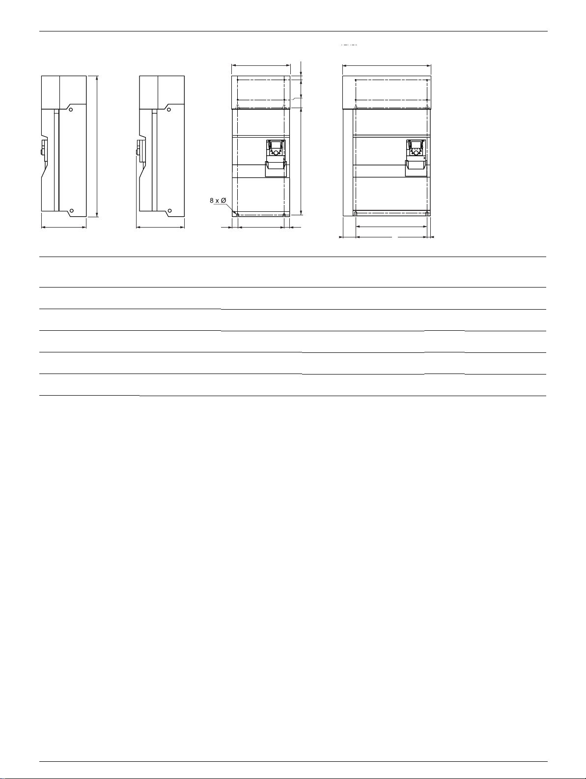
With 2 option cards (1)With 0 or 1 option card (1) ATV71H MT4300 to MT4400 with braking unit
b
377 mm
(14.77 in)
392 mm
(15.43 in)
MT a
275,4125
(12.60)
4150,2100
(14.17)
4200
(13.39)
4250
(17.32)
4300,4400,4450
(23.43)
mm
(in.
320
360
340
440
595
to MT4400
a
==G
b
mm
)
(in.
)
920
(36.22)
1022
(40.23)
1,190
(46.62)
1,190
(46.62)
1,190
(46.62)
G
mm
(in.)
250
(9.84)
298
(11.73)
285
(11.22)
350
(13.78)
540
(21.26)
mm
(in.)
650
(25.59)
758
(29.84)
920
(36.22)
920
(36.22)
920
(36.22)
HK1KK2
H
670 (26.37)
540 mm (21,26 in)
102,5 mm
(4.03 in)
K
mm
(in.
15
)
0
K1
mm
(in.
)
(5.91)75(2.95)30(1.18)
150
91)72(2.83)30(1.18)
(5.
0
15
(5.91)75(2.95)30(1.18)
0
15
(5.91)75(2.95)30(1.18)
0
15
(5.91)75(2.95)30(1.18)
27,5 mm
(1.08 in)
K2
mm
(in.)
Ø
mm
n.)
(i
11.5
(0.45)
11.5
(0.45)
11.5
(0.45)
11.5
(0.45)
11.5
(0.45)
For
Weight
screws
M10 92
M10 108
M10 116
M10 163
M10 207
kg
(lb.
(132)
(163)
(255)
(358)
(455)
)
ATV71
10
Page 10
Installi
ng the
DC chok
CTi Automation - Phone: 800.894.0412 - Fax: 208.368.0415 - Web: www.ctiautomation.net - Email: info@ctiautomation.net
This should be performed after mounting the drive and before wiring it. If a MT-VW3 A7 101 braking module is used, install the module on
the drive before installing the DC choke.
During installation, ensure that no liquid, dust or conductive objects fall into the drive.
e
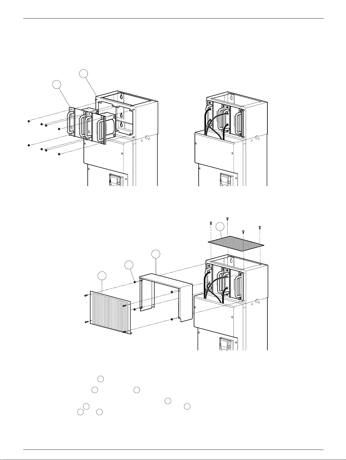
Example of installing DC chokes on an MT4250
1
2
6
3
4
5
- Mount the DC choke chassis on the wall, on top of the drive. Ensure that the chassis is tightl y secured to the drive to maintain the
IP54 seal of the ventilation duct.
- Then install the DC choke on the chassis using the nuts provided.
- Connect the choke between the PO and PA/+ terminals on the drive (see next page and note below).
- Connect the grounding strip between the DC choke chassis and the drive.
- Then mount the cover on the chassis and secure it with the nuts provided.
- Then mount panels and using the sc rews provided.
5 6
1
2 1
1
3 4
Once the choke has been installed, the degree of protection of the top of the drive is IP31.
The number of DC chokes supplied with the drive varies according to the drive rating.
Note:
11
Page 11
C
onnecting the
DC chok
CTi Automation - Phone: 800.894.0412 - Fax: 208.368.0415 - Web: www.ctiautomation.net - Email: info@ctiautomation.net
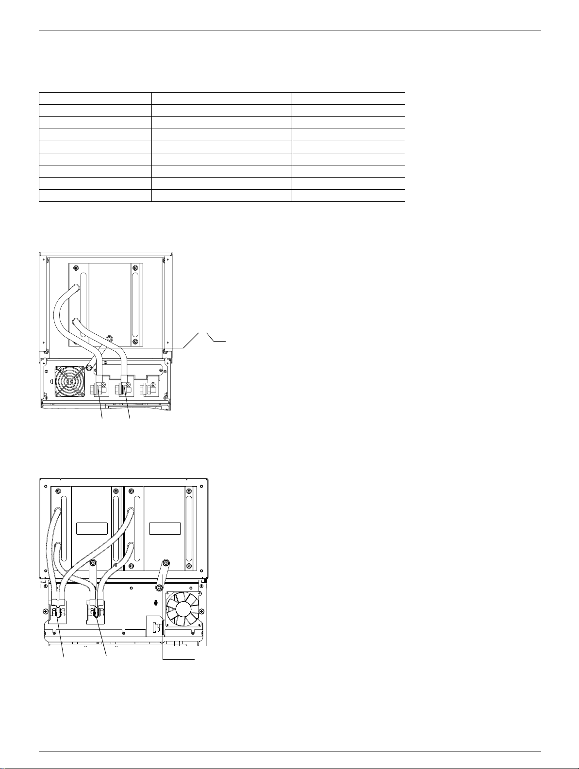
1 to 4 chokes can be connected in parallel as described in the examples below.
e
Table showing possible drive/choke combinations
Drive Number of chokes in parallel Choke model
MT275 1 DC-CHOKE 5
MT2100 1 DC-CHOKE 6
MT4125 1 DC-CHOKE 1
MT4150 1 DC-CHOKE 2
MT4200 1 DC-CHOKE 4
MT4250 2 DC-CHOKE 1
MT4300 2 DC-CHOKE 3
MT4400 2 DC-CHOKE 4
Example 1:
MT275... MT2100,
MT4125... MT4200
Grounding
strip
PO PA/+
Example 2:MT4250... MT4400
Example 3:
ATV71HC31N4
PO.1 PA/+ PO.2
PO PA/+
12
Grounding
strip
Page 12
D
erating as a function of temperature and switching frequency
CTi Automation - Phone: 800.894.0412 - Fax: 208.368.0415 - Web: www.ctiautomation.net - Email: info@ctiautomation.net
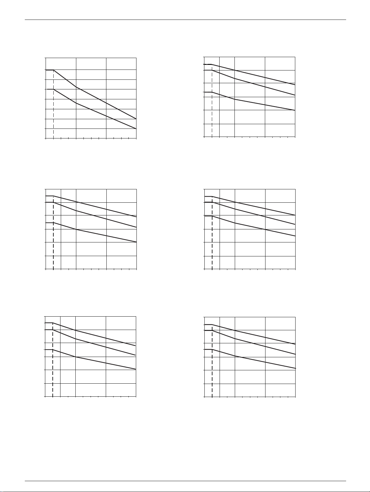
Derating curves for the drive current In as a function of the temperature and s witching frequency.
MT275 , MT2100 MT4125
120
In = 100
90
80
70
60
50
40
30
%
50°C (122°F)
60°C (140°F)
2,5 kHz 4 kHz 6 kHz 8 kHz
120
110
In = 100
%
80
67
60
40
20
0
Switching frequency
MT4150 MT4200
120
109
In = 100
80
70
60
40
%
40°C (104°F)
50°C (122°F)
60°C (140°F)
120
107
In = 100
%
78
60
40
40°C (104°F)
50°C (122°F)
60°C (140°F)
2,5 kHz 4 kHz 6 kHz 8 kHz
Switching frequency
40°C (104°F)
50°C (122°F)
60°C (140°F)
20
0
2,5 kHz 4 kHz 6 kHz 8 kHz
20
0
2,5 kHz 4 kHz 6 kHz 8 kHz
Switching frequency
MT4250 MT4300
120
111
In = 100
%
80
71
60
40
20
0
2,5 kHz 4 kHz 6 kHz 8 kHz
40°C (104°F)
50°C (122°F)
60°C (140°F)
120
109
In = 100
%
80
72
60
40
20
0
2,5 kHz 4 kHz 6 kHz 8 kHz
Switching frequency
For intermediate temperatures (e.g. 55°C (131°F)), interpolate bet ween 2 curves.
Switching frequency
40°C (104°F)
50°C (122°F)
60°C (140°F)
Switching frequency
13
Page 13

D
erating as a function of the temperature and the switching frequency
CTi Automation - Phone: 800.894.0412 - Fax: 208.368.0415 - Web: www.ctiautomation.net - Email: info@ctiautomation.net
MT4400
%
120
108
In = 100
77
40°C (104°F)
50°C (122°F)
60
40
20
0
2,5 kHz 4 kHz 6 kHz 8 kHz
60°C (140°F)
Switching frequency
For intermediate temperatures (e.g. 55°C (131°F)), interpolate bet ween 2 curves.
14
Page 14
M
ounting in a wall-mounted or floor-standing enclosure
CTi Automation - Phone: 800.894.0412 - Fax: 208.368.0415 - Web: www.ctiautomation.net - Email: info@ctiautomation.net
Install the drive vertically at ± 10°. Do not place it close to heating elements.
Installing the heatsink inside the enclosure
The power dissipated by the drive power components is given in the table below.
Dissipated power
These levels of power dissipation are given for operation at nominal load and for a switching
frequency of 2.5 Hz.
Figure 1
2
1
MT
MT Dissipated power MT Dissipated power
W W
275 1,715 4300 4,930
2100 2,204 4400 5,873
4125 2,403
4150 2,593
4200 2,726
4250 3,812
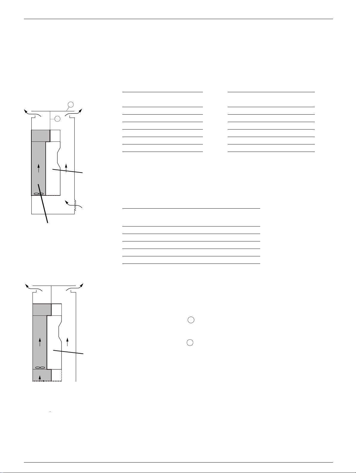
The drive has a fan for cooling the power components. The air is circul ated f rom the bottom t o
the top of the uni
is isolated from the control section by IP54 protection. The DC choke extends this duct while
maintaining IP54 protection.
The drive dissipates a great deal of power, which must be evacuated to the outside of the
closure.
en
Air inlets and out
ual to the v
eq
t via a duct (the duct is shown shaded gray on the diagram opposite). This duct
lets must be provided to ensure that the flow of air in the enclosure is at least
alue given in the table below for each drive.
Figure 2
Cooling duct for power
components.
IP54 protection(nema 12)
MT
MT
275,4125 402 236
2100,4150 774 455
4200 745 438
4250 860 506
4300,4400 1,260 742
Several methods of evacuation are possible. The followi ng is a propos ed met hod fo r IP23 a nd
IP54 mounting.
Flow rate
3
m
/hour ft3/min
IP23 mounting (standard operating conditions):
Figure 1
Install the drive on an enclosure baseplate.
Install the DC choke in accordance with the mounting recommendations.
The simplest mounting is to extend the IP54 duct between the upper outlet of the DC choke
d the top o
an
DC choke.
The hot air is thus evacuated to the outside and does not contribute towards increasing the
nternal temper
i
It is advisable to add a plate approximately 150 mm from the top of the encl osure over t he
air outlet opening to prevent foreign bodies falling into the drive cooling duct.
The air inlet can be via a grille on the bottom front panel of the enclosure door, in accordance
h the required flow
wit
Figure 2
It is advisable to use a kit for IP31/NEMA type 1 conformity (to be ordered as an option) for
taching the powe
at
DC choke, and has an IP54 duct to help guide the incoming air.
f the enclosure . Fixing points are provided for this purpose on the top of the
ature of the enclosure.
r cables. The design of the IP31 kit is based on the same principle as the
1
2
rates given in the above table.
Note:
- If the air in the power circuit is totally evacuated to the outsi de, very li t tle power is di ssi pated
nside the enclosure.
Kit for IP31 or NEMA
type 1 conformity
i
flange mounting (see the next page).
- Connect all the additional metal parts to ground.
In this case, use the dissipated power table for dust and damp proof
15
Page 15

M
ounting in a wall-mounted or floor-standing enclosure
CTi Automation - Phone: 800.894.0412 - Fax: 208.368.0415 - Web: www.ctiautomation.net - Email: info@ctiautomation.net
Mounting the heatsink inside the enclosure (continued)
IP54 mounting (standard operating conditions):
1
The drive must be mounted in an IP54 enclosure in certain environmental conditions: dust,
corrosive gases, high humidity with risk of condensation and dripping water, splashing liquid, etc.
MT
2
4
3
The simplest way of obtaining an enclosure with IP54 protection is to follow the mounting
recommendations for IP
1 Do not make an air outlet hole for the control section. Do not make an air inlet hole in the
enclosure door. Th
via a plinth added for the purpose.
2 Add the IP31 or NEMA type 1 conformity kit in accordance with the mounting instructi ons.
3 Add an enclosure baseplate designed to provide IP54 protection around the power cables.
4 Add an air evacuation duct between the baseplate and the duct of the IP31 or NEMA
pe 1 conformity kit.
ty
be mounted. Drill a hole in the base of the enclosure to allow air t o enter. Place seals around
the duct that has been added to maintain IP54 protection.
5 Add a 200 mm plinth at the bottom of the enclosure with grilles to allow air to ent er.
6 Use the dissipated power table below to calculate the size of the enclos ure.
Note: Connect all the additional metal parts to ground.
23 protection with the following 5 additional points:
e air for the power section will enter through the bottom of the enclosure
The IP31 or NEMA type 1 conformity kit en
ables an extension duct to
Power dissipated inside the enclosure by the control section
5
(for calculating the size of the enclosure)
These power ratings are given for operation at nominal load and for the factory-set switching
frequency.
MT Dissipated power (1) MT Dissipated power (1)
W W
275 154 4300 493
2100 154 4400 586
4125 237
4150 261
4200 296
4250 350
(1)Add 7W to this value for each option card added
Dust and damp proof flange mounting (heatsink outside
the enclosure)
This mounting is used to reduce the dissipated power in the enclosure by locating the power
section outside the enclosure.
This requires the use of the dust and damp proof flange mounting kit MT-VW3A9509.
ease refer to the
(pl
The degree of protection for the drive mounted in this way becomes IP54.(nema 12)
To mount the kit on the drive, please refer to the manual supplied with th e kit.
Use the dissipated power table above to calculate the size of the enclosure.
In this case the DC choke can be mounted directly on the back of the enclosure.
catalog).
16
Page 16

M
ounting in a wall-mounted or floor-standing enclosure
CTi Automation - Phone: 800.894.0412 - Fax: 208.368.0415 - Web: www.ctiautomation.net - Email: info@ctiautomation.net
If the hot air exiting the drive is not ducte d and evacuated to the ou tside, it may be sucked back in again, which would render th e ventilati on
ineffective. To prevent this, leave sufficient free space around the drive, as shown below.
The wall-mounted or floor-standing enclosure must be cooled in order to evacuate the dissipated heat.
u h1
u h2
MT h1 h2
mm in. mm in.
275,2100,4125 100 3.94 100 3.94
4150,4200,4250 150 5.90 150 5.90
4300,4400 200 7.87 150 5.90
Free space in front of the drive: 10 mm (0.39 in.) minimum
17
Page 17

Installi
ng the
kit f
IP31/NEMA t
CTi Automation - Phone: 800.894.0412 - Fax: 208.368.0415 - Web: www.ctiautomation.net - Email: info@ctiautomation.net
On MT275 to MT2100 and MT4125 to MT4400 drives, the cable shielding can be attached and connected to ground using one of the
following two kits:
• Kit for IP31 conformity (MT-VW3 A9 109)
• Kit for NEMA Type 1 conformity (MT-VW3 A9 209 )
or
ype 1 conformity
This kit is not supplied with the drive. It must be ordered separately (please refer to the
2
3
6
4
catalog). It is mounted under the drive as shown below.
5
1
- Mount the chassis on the wall or in the back of the enclosure under the drive. Ensure that the chassis is tight ly secured to the drive
to maintain the IP54 seal of the ventilation duct. Use the 2 clamps which fit into the drive’s carrying holes for this purpose .
- Mount the nema 1 box on the kit chassis using the screws provided.
- Mount the clamp to ensure emc plate is securely grounded.
- Mount the conduit cover on the nema 1 box using the screws provided.
- Then mount the top cover cover on the box plate using the screws provided.
1
5
2
3
4
6
Note:
This kit can be used to help guide the incoming air. It is supplied with a seal to ensure IP54 protection between the duct and the drive.
Close the carrying holes on the drive with the plastic plugs provided for the purpose.
5
18
Page 18

Installi
ng the
kit f
IP31/NEMA t
ity
CTi Automation - Phone: 800.894.0412 - Fax: 208.368.0415 - Web: www.ctiautomation.net - Email: info@ctiautomation.net
or
ype 1 conform
MT-VW3 A9 209 ... 216 MT-VW3 A9 209 ... 213,
b
c
MT-VW3 a
A9 209 320
A9 210 360
A9 211 340
A9 212 440
A9 213 595
A9 214
A9 215 (890)
A9 216 1,120
mm
(in.)
(12.6)
(14.17)
(13.39)
(17.32)
(23.43)
670
(23.43)
(35.04
(44.09
215
H3
H1
GG1 G2
==
aa a
b
mm
(in.
220
(8.66)
300
(11.81)
315
(12.4)
375
(14.76)
375
(14.76)
375
(14.76)
475
(18.7)
475
(18.7)
mm
)
(in.)
367
(14.45)
367
(14.45)
369
(14.53)
424
(16.69)
472
(18.58)
472
(18.58)
474
(18.66)
474
(18.66)
H2
c
G
mm
(in.)
250
(9.84)
298
(11.73)
285
(11.22)
350
(13.78)
540
(21.26)
540
(21.26)
835
(32.87)
495
(19.49)
MT-VW3 A9 214 MT-VW3 A9 216
G1
mm
(in.
-
-
-
-
-
-
-
-
-
-
102.5
(4.03)
-
-
-
-
G
G2
mm
)
n.)
(i
-
-
-
-
-
-
-
-
-
-
27.5
(1.08)
-
-
-
-
G3
mm
(in.
-
-
-
-
-
-
-
-
-
-
-
-
-
-
70
(2.76)
)
=
H1
mm
n.)
(i
95
(3.74)65(2.56)75(2.95)
172
(6.77)65(2.56)75(2.95)
240
(9.40)35(1.37)55(2.15)
250
(9.84)65(2.56)75(2.95)
250
(9.84)65(2.56)75(2.95)
250
(9.84)65(2.56)75(2.95)
350
(13.78)65(2.56)75(2.95)
350
(13.78)65(2.56)75(2.95)
G
H2
mm
(in.
G3
H3
mm
)
(in.)
G
Ø
mm
(in.)
11.5
(0.45)
11.5
(0.45)
11.5
(0.45)
11.5
(0.45)
11.5
(0.45)
11.5
(0.45)
11.5
(0.45)
11.5
(0.45)
sc
=
For
rews
M10
M10
M10
M10
M10
M10
M10
M10
19
Page 19

L
ocation of the charging
LED
CTi Automation - Phone: 800.894.0412 - Fax: 208.368.0415 - Web: www.ctiautomation.net - Email: info@ctiautomation.net
Before working on the drive, turn it off, wait until the red capacitor charging LED has gone out, then measure the DC bus voltage.
Location of the capacitor charging LED
Red LED indicating that the DC bus is powered up
Procedure for measuring the
DC bus voltage
DANGER
HAZARDOUS VOLTAGE
Read and understand the instructions on page 4 before performing this procedure.
Failure to follow this instruction will re su lt in dea th or se rio us injury.
The DC bus voltage can exceed 1,000 VDC. Use a properly rated voltage s ensing dev ice when p erforming t his pro cedure. To measure t he
DC bus voltage:
1 Disconnect the drive power supply.
2 Wait for the capacitor chargi ng LE D to go off.
3 Measure the voltage of the DC bus between the PA/+ and PC/- terminals to check whether the voltage is less than 45 VDC. Refer to
4 If the DC bus capacitors have not discharged completely, contact Motortronics agent (do not repair or operate the drive).
25 for the layout of the power terminals.
e
pag
20
Page 20

Installi
ng option cards
CTi Automation - Phone: 800.894.0412 - Fax: 208.368.0415 - Web: www.ctiautomation.net - Email: info@ctiautomation.net
These should ideally be installed once the drive is mounted and before wiring it.
Check that the red capacitor charging LED has gone out. Measure the DC bus voltage in accordance with the procedure indicated on
20.
page
The option cards are installed under the drive control front panel. Remove the graphic keypad then take off the control front panel as
d below.
indicate
Remove the control front panel
1
• Using a screwdriver, press down on
the catch and pull to release the lefthand part of the control front panel
2
• Do the same on the
right-hand side
3
Removing the empty option card support
MT275 to MT2100 and MT4125 to MT4400 drives are supplied with an empty option card support. If adding an
I/O or communication option card or a “Controller Inside” programmable card, remove the support
This card support serves no purpose if one or more option cards are used.
• Pivot the control front panel
and remove it
following the instructions below.
1
2
1
Open the empty option card support
2
Release the support from its hooks and remove it
21
Page 21

Installi
ng option cards
CTi Automation - Phone: 800.894.0412 - Fax: 208.368.0415 - Web: www.ctiautomation.net - Email: info@ctiautomation.net
Installing an encoder interface card
There is a special slot on the drive for adding an encoder interface card.
• First remove the empty option card support if it is still in place, as
shown on the previous page, so that you can access the slot for the
encoder feedback card.
• If an I/O or communication option card has already been installed,
remove it so you can access the slot for the encoder feedback card.
• After installing the encoder interface card, replace the empty card
support or the option card(s).
Installing an I/O extension card or a communication card
2
1
1
2
Replacing the control front panel
3
3
Replace the control front panel over the option card (same procedure as for installing
the option card, see and )
1 2
Position the option card on the clasps
Pivot the card until it clicks into place
22
Page 22

Wiri
ng recommendations
CTi Automation - Phone: 800.894.0412 - Fax: 208.368.0415 - Web: www.ctiautomation.net - Email: info@ctiautomation.net
Power
The drive must be connected to the protective ground. To comply with local regulations concerning high leakage currents (above 3.5 mA),
use at least a 10 mm² (AWG 6) protective conductor or 2 protective conduct ors with the same cross-section as the power supply conductors.
DANGER
HAZARDOUS VOLTAGE
Ground equipment using the ground connecting point provided as shown i n the figure below. The drive panel must be
properly grounded before power is applied.
Failure to follow these instructions will result in death or serious injury.
Drive
Drive
Drive
• Check whether the resistance to the protective ground is one ohm or less.
• If several drives are to be connected to the protective ground, each drive must be connected
directly to this
ground as shown opposite.
WARNING
IMPROPER WIRING PRACTICES
• The MT drive will be damaged if input line voltage is applied to the output terminals (U/T1,V/T2,W/T3).
• Check the power connections before powering up the MT drive.
• If replacing another drive, verify that all wiring connections to the MT drive comply with all wiring instructions in this
al.
manu
Failure to
When upstream protection by means of a “residual current device” is required by t he installation sta ndards, a type A device sh ou
for single phas
• HF current filtering
• A time delay which prevents tripping caused by the load from st
devices. In this case, choose devices with immunity against nuisance tripping, for example “residual current devices” with reinforced
immunity from the
follow these instructions can result in death or serious injury.
e drives and type B for 3-phase drives. Choose a suitable model integrating:
ray capacitance on power-up. The t
s.i range.
ld be used
ime delay is not possible for 30 mA
If the installation includes several drives, provide one “residual current device” per drive.
WARNING
INADEQUATE OVERCURRENT PROTECTION
• Overcurrent protective devices must be properly coordinated.
• The Canadian Electricity Code and the National Electrical Code require branch circuit protect
recommended on the drive nameplate to achieve published short-circuit current ratings.
• Do not connect the drive to a power feeder whose short-circuit
in the tables on pages
Failure to follow these instructions can result in de
8 and 9.
ath or serious injury.
capacity exceeds the driv
ion. Use the fuses
e short-circuit current indicated
23
Page 23

Wiri
ng recommendations
CTi Automation - Phone: 800.894.0412 - Fax: 208.368.0415 - Web: www.ctiautomation.net - Email: info@ctiautomation.net
Keep the power cables separate from circuits in t he installation with low-level signal s (detectors, PLCs, measuring apparatus, v ideo, phone).
The motor cables must be at least 0.5 m (20 in.) long.
Do not immerse the motor cables in water.
Do not use surge arresters or power factor correction capacitors on the variable speed drive output.
CAUTION
IMPROPER USE OF A BRAKING RESISTOR
• Only use the braking resistor values recommended in our catalogs.
• Wire a thermal overload relay in the sequence or configure the braking resistor protection (please refer to the
Programming Manual) so that the drive p
Failure to follow these instructions can re
Control
Keep the control circuits away from the power circuits. For control and speed reference circuits, we recommend using shielded twisted
cables with a pitch of between 25 and 50 mm (0.98 and 1.97 in.) and connecting the s hielding to ground at each end.
ower section AC supply is disconnected in the event of a fault.
sult in equi
pment damage.
If using conduit, do not lay the motor, power supply and control cables in the same conduit. Keep the metal conduit containing the power
supply cables
containing the power supply cables at least 31 cm (12 in.) away from the metal conduits contai ni ng th e contro l cabl es. If it is necessary for
control and power cables to cross each other, be sure they cross at right angles.
at least 8 cm (3 in.) away from the metal conduit containing the control cables. Keep the non-metal conduits or cable ducts
Length of motor cables
0 ... 50 m
(0 ... 164 ft)
Shielded
MT275 to MT2100
MT4125 to MT4400
Note: On old generation motors or those with poor insulation it is advisable to use a motor choke with 5 m (16.4 ft) of cable.
Choice of associated components:
Please refer to the catalog.
cable
Unshielded
cable
50 ... 100 m
(164 ... 328 ft)
100 ... 200 m
(328 ... 656 ft)
Motor
hoke
c
Motor choke 2 motor chokes in series
200 ... 300 m
(656 ... 984 ft)
300 ... 400 m
(984 ... 1,312 ft)
2 motor chokes in
400 ... 600 m
(1,312 ... 1,968 ft)
series
24
Page 24

P
ower terminals
CTi Automation - Phone: 800.894.0412 - Fax: 208.368.0415 - Web: www.ctiautomation.net - Email: info@ctiautomation.net
Access to the power terminals
To access the power terminals, unscrew the front panel and remove the protective cover
Terminals for
DC choke
Fan power
supply
DC bus power supply
• Power section AC supply
• Output to the motor
• Connections to ground
• Output to braking resistor (up
to MT4250 rating only)
Characteristics and functions of the power terminals
Terminal Function MT
3 x t Protective ground connection terminals All ratings
R/L1, S/L2, T/L3 (1) Power supply All ratings
PO DC choke connection
PA/+ DC bus + polarity and DC choke connection All ratings
PC/- DC bus - polarity All ratings
PA Output to braking resistor MT275 , MT2100
PB Output to braking resistor
U/T1, V/T2, W/T3 Output to the motor All ratings
RO, SO, TO
Separate power supply for the fan when the drive is
powered by t
he DC bus only
BU+, BU- + and - polarities to be connected to the braking unit MT4300 to MT4400
X20, X92, X3 Braking unit control cable connection
(1) From the MT4300 upwards, there are no braking resistor connection terminals on the drive as the braking uni t is optional (please refer
to the catalog). The braking resistor is then connected to the braking unit.
MT275 , MT2100
MT4125 to MT4400
MT4125 to MT4250 (2)
MT2100
MT4150
to MT4400
Refer to the braking unit User’s Manual.
25
Page 25

P
CTi Automation - Phone: 800.894.0412 - Fax: 208.368.0415 - Web: www.ctiautomation.net - Email: info@ctiautomation.net
ower terminals
MT275 , MT4125
Front view
320 (12.54)
View from above
View from below
70 (2.74) 60 (2.35)
115 (4.50)
M12
5 (0.2)
PC/-PA/+PO
M10
M8
295 (11.55)
230 (9.01)
172 (6.74)
U/T1 V/T2
R/L1
S/L2 T/L3
W/T3
PA PB
225 (8.81)
100 (3.92)
65 (2.55)
14 (0.55)
M10
85(3.33)
105(4.11)
M10
60(2.35)
50 (1.96)
Max. wire size/terminal tightening torque
Drive terminals L1/R, L2/S, L3/T, U/T1, V/T2, W/T3 PC/-, PO, PA/+ PA, PB
2
2 x 100 mm
2 x 250 MCM / 212 lb.in 2 x 250 MCM / 360 lb.in 250 MCM / 106 lb.in
/ 24 Nm 2 x 100 mm2 / 41 Nm 60 mm2 / 12 Nm
38 (1.49)57(2.23)
32 (1.25)
26
Page 26

P
ower terminals
CTi Automation - Phone: 800.894.0412 - Fax: 208.368.0415 - Web: www.ctiautomation.net - Email: info@ctiautomation.net
MT2100 , MT4150
Front view
View from above
320 (12.54)
125 (4.90)
149(5.84)
67 (2.62)
M12
5 (0.2)
PC/-PA/+PO
View from below
Fan terminals (1)
70 (2.74)
265 (10.38)
250 (9.80)
U/T1 V/T2
R/L1
S/L2 T/L3
W/T3
PA PB
328 (4.02)
260 (10.18)
200 (7.83)
155 (6.07)
27 (1.06)
55,5 (2.17)
34 (1.33)
58 (2.27)
M10
79,5 (3.11)
217 (8.50)
M10
60 (2.35)
M10
38 (1.49)
M8
62 (2.43)
Max. wire size/terminal tightening torque
Drive terminals L1/R, L2/S , L3/T, U/T1, V/T2, W/T3 PC/-, PO, PA/+ PA, PB RO, SO, TO
2
2 x 100 mm
/ 24 Nm 2 x 150 mm2 / 41 Nm 60 mm2 / 12 Nm 5.5 mm2 / 1.4 Nm
2 x 250 MCM / 212 lb.in 2 x 250 MCM / 360 lb.in 250 MCM / 106 lb.in AWG 10 / 12 lb.in
(1)
137 (5.37)
(1)Power supply for the fans, compulsory if the drive is powered by the DC bus only. Do not use if the drive has a 3-phase AC supply via
L1/R, L2/S, L3/T.
27
Page 27

P
ower terminals
CTi Automation - Phone: 800.894.0412 - Fax: 208.368.0415 - Web: www.ctiautomation.net - Email: info@ctiautomation.net
MT4200
View from above
Front view
80 (3.13) 56 (2.19) 58 (2.28)
317 (12.43)
PA/+
View from below
115 (4.50)
M12
PC/-PO
Fan terminals (1)
321 (12.58)
322 (12.62)
281 (11.01)
252 (9.87)
U/T1 V/T2
R/L1
S/L2 T/L3
W/T3
PA PB
252 (9.87)
99 (3.88)
80 (3.13)
76 (2.98)
18 (0.71)
43 (1.68)
72 (2.83)
80 (3.13)
M10
75 (2.94)
M10
75 (2.94)
257 (10.07)
M10
M8
68 (2.66)
38 (1.49)
Max. wire size/terminal tightening torque
Drive terminals L1/R, L2/S, L3/T, U/T1, V/T2, W/T3 PC/-, PO, PA/+ PA, PB RO, SO, TO
2
2 x 120 mm
/ 24 Nm 2 x 120 mm2 / 41 Nm 120 mm2 / 24 Nm 5.5 mm2 / 1.4 Nm
2 x 250 MCM / 212 lb.in 2 x 250 MCM / 360 lb.in 250 MCM / 212 lb.in AWG 10 / 12 lb.in
(1)Power supply for the fans, compulsory if the drive is powered by the DC bus only. Do not use if the drive has a 3-phase AC supply via
L1/R, L2/S, L3/T.
28
(1)
Page 28

P
ower terminals
CTi Automation - Phone: 800.894.0412 - Fax: 208.368.0415 - Web: www.ctiautomation.net - Email: info@ctiautomation.net
MT4250
View from above
47 (1.84)
Front view
100 (3.92) 150 (5.88)
319,50 (12.52)
PO PA/+ PC/-
View from below
319,50 (12.52)
112 (4.39)
40 (1.57)
M12
Fan terminals (1)
286 (11.20)
321 (12.58)
270 (10.58)
251 (9.83)
U/T1 V/T2
R/L1
S/L2 T/L3
W/T3
PA PB
260 (10.18)
104 (4.07)
80 (3.13)
74 (2.90)
114 (4.47) 102 (4.00)
21 (0.82) 104 (4.07) 102 (4.00)
102 (4.00)74 (2.90)
357 (13.99)
M12
M12
M12
M8
38 (1.49)
Max. wire size/terminal tightening torque
Drive terminals L1/R, L2/S, L3/T, U/T1, V/T2, W/T3 PC/-, PO, PA/+ PA, PB RO, SO, TO
2
2 x 150 mm
/ 41 Nm 2 x 150 mm2 / 41 Nm 120 mm2 / 24 Nm 5.5 mm2 / 1.4 Nm
2 x 350 MCM / 360 lb.in 2 x 350 MCM / 360 lb.in 250 MCM / 212 lb.in AWG 10 / 12 lb.in
(1)Power supply for the fans, compulsory if the drive is powered by the DC bus only. Do not use if the drive has a 3-phase AC supply via
L1/R, L2/S, L3/T.
(1)
68 (2.66)
29
Page 29

P
ower terminals
CTi Automation - Phone: 800.894.0412 - Fax: 208.368.0415 - Web: www.ctiautomation.net - Email: info@ctiautomation.net
MT4300 , MT4400
Front view
View from above
PO PA/+ PC/-
View from below
319,50 (12.52)
102 (4.00)
145 (5.68)
87 (3.41)
100 (3.92) 112 (4.39)
2 x M12
Fan terminals (1)
67 (2.62)
70 (2.74)
98 (3.84)
271 (10.61)
251 (9.83)
R/L1
U/T1 V/T2
S/L2 T/L3
W/T3
322 (12.62)
36 (1.41)
43 (1.67)
113,5 (4.45) 175 (6.85)
173,5 (68.01)
130 (5.09)
M12
176,5 (69.19)
175 (6.85)175 (6.85)
M12
M12
Max. wire size/terminal tightening torque
Drive terminals L1/R, L2/S, L3/T, U/T1, V/T2, W/T3 PC/-, PO, PA/+ RO, SO, TO
2
4 x 185 mm
/ 41 Nm 4 x 185 mm2 / 41 Nm 5.5 mm2 / 1.4 Nm
3 x 350 MCM / 360 lb.in 3 x 350 MCM / 360 lb.in AWG 10 / 12 lb.in
(1)Power supply for the fans, compulsory if the drive is powered by the DC bus only. Do not use if the drive has a 3-phase AC supply via
L1/R, L2/S, L3/T.
(1)
30
Page 30

Control t
erminals
CTi Automation - Phone: 800.894.0412 - Fax: 208.368.0415 - Web: www.ctiautomation.net - Email: info@ctiautomation.net
Access to the control terminals
Removing the terminal card
To access the control terminals,
open the cover on the control front panel.
1
2
Arrangement of the control terminals
SW1
SW2
R1A
R1B
R1C
R2A
R2C
+10
AI1+
AI1-
COM
AI2
AO1
COM
To make it easier to wire the drive control section,
the control terminal card can be removed.
• Undo the screw until the spring is fully extended.
• Remove the card by sliding it downwards.
IMPROPERLY SECURED TERMINAL CARD
When replacing the control terminal card, it is essential to
fully tighten the captive screw.
Failure to follow this instruction can result in
eq
Logic input switch
Source
Int
Sink
Ext
LI6 input switch
PTC LI
Factory setting: Source
Factory setting: LI
uipment damag
CAUTION
e.
Maximum wire size:
2.5 mm² – AWG 14
LI2
LI3
LI4
LI5
0V
P24
LI1
Note: The
MT is supplied with a link between the PWR and +24 terminals.
LI6
+24
PWR
RJ45
RJ45 connector
Max. tightening torque:
0.6 Nm – 5.3 lb.in
31
Page 31

Control t
erminals
CTi Automation - Phone: 800.894.0412 - Fax: 208.368.0415 - Web: www.ctiautomation.net - Email: info@ctiautomation.net
Characteristics and functions of the control terminals
Terminal Function Electrical characteristics
R1A
R1B
R1C
R2A
R2C
Common point C/O contact (R1C) of
programmab
N/O contact of programmable relay R2
le relay R1
• Minimum swi
• Maximum switching capacity on resistive load:
5 A for 250 VAC or 3
• Maximum switching curren
2 A for 2
• Reaction ti
• Service life: 100,000 operations at max. switching power
tching capacity: 3 mA for 24 VDC
50 VAC or 30 VDC
me: 7 ms ± 0.5 ms
0 VDC
t on inductive load (cos ϕ = 0.4 L/R = 7 ms):
+10 + 10 VDC power supply for reference
AI1+
AI1-
COM Analog I/O common 0V
AI2 Depending on software configuration:
COM Analog I/O
AO1 Depending on software configuration:
P24 Input for external +24 VDC control
0V Logic input common and 0V of P24
1
LI
LI2
LI3
LI4
LI5
LI6 Depending on the position of the SW2
+24 Logic input power supply SW1 switch in Source or Sink Int position
entiometer
pot
1 to 10 k
Differential analog input AI1 • -10 to +10 VDC (max. safe voltage 24 V)
Analog voltage input
or
Analog current input
Analog voltage output
or
Analog current output
power s
external power supply
Programmable logic inputs • +24 VDC (max. 30 V)
swi
or
Ω
common 0V
upply
tch:
- Programmable lo
- Input for PTC probes
gic input
• + 10 VDC (10.5 V ± 0.5V)
• 10 mA max.
• Reaction time: 2 ms ± 0.5 ms, 11-bit resolution + 1 sign bit
• Accuracy ± 0.6% for ∆θ = 60°C (140°F), linearity ± 0.15% of max. value
• Analog input 0 to +10 VDC (max. safe voltage 24 V),
impedance 30 kΩ
or
• Analog input X – Y mA, X and Y can be programmed from 0 to 20 mA,
• Impedance 250 Ω
• Reaction time: 2 ms ± 0.5 ms
• 11-bit resolution, accuracy ± 0.6% for ∆θ = 60°C (140°F), linearity ± 0.15% of max.
ue
val
• Analog output 0 to +10 VDC, load impedance greater than 50 kΩ
or
• Analog output X – Y mA, X and Y can be programmed from 0 to 20 mA
• Max. load impedance 500 Ω
• 10-bit resolution, reaction time: 2 ms ± 0.5 ms
• Accuracy ± 1% for ∆θ = 60°C (140°F), linearity ± 0.2% of max. value
• +24
VDC (min. 19 V, max. 30 V)
• Power 30 Watts
0V
• Impedance 3.5 kΩ
• Reaction time: 2 ms ± 0.5 ms
SW2 switch on LI (factory setting)
• Same characteristics as logic inputs LI1 to LI5
or
SW2 switch on PTC
• Trip threshold 3 kΩ, reset threshold 1.8 kΩ
• Short-circuit detection threshold < 50 Ω
• +24 VDC power supply (min. 21 V, max. 2 7 V), pro tec ted aga ins t short -c ircui ts and
verloads
o
•
Max. current available for customers 200 mA
SW1 switch State 0 State 1
Source (factory setting) < 5 VDC > 11 VDC
Sink Int or Sink Ext > 16 VDC < 10 VDC
SW1 switch in Sink Ext position
• Input for external +24 VDC power supply for the logic inputs
PWR Power Removal safety function input
32
When PWR is not connected to the
24 V, the motor cannot be started
ompliance with functiona
(c
standard EN 954-1 and IEC/EN 61508)
l safety
• 24 VDC power supply (max. 30 V)
• Impedance 1.5 kΩ
• State 0 if < 2V, state 1 if > 17V
• Reaction time: 10 ms
Page 32

Opti
on terminals
CTi Automation - Phone: 800.894.0412 - Fax: 208.368.0415 - Web: www.ctiautomation.net - Email: info@ctiautomation.net
Logic I/O option card terminals (MT-VW3 A3 201)
Logic input switch SW3
SW3
Source
Sink
Ext
Int
Factory setting: Source
Maximum wire size:
1.5 mm² – AWG 16
R3A
R3C
R3B0V-10
+24
LI7
LI8
LI9
LI10
TH1+
TH1-
L01
L02
CLO
0V
Characteristics and functions of the terminals
Terminal Function Electrical characteristics
R3A
R3B
Common point C/O contact R3C of
programmab
le relay R3
R3C
-10 -10 VDC power supply for reference
entiometer 1 to
pot
10 k
Ω
+24 Logic input power supply SW3 switch in Source or Sink Int position
LI7
Programmable logic inputs • +24 VDC power supply (max. 30 V)
LI8
LI9
LI10
• Minimum switchi
ng capacity: 3 mA for 24 VDC
• Maximum switching capacity on resistive load:
5 A for 250 VAC or 30 VDC
• Maximum switching capacity on inductive load (cos ϕ
2 A for 250
VAC or 30 VDC
• Reaction time: 7 ms ± 0.5 ms
• Service life: 100,000 operations
•- 10 VDC (-10.5 V ± 0.5V)
• 10 mA max.
• +24 VDC power supp
ly (min. 21 V, max. 27 V),
overloads
• Max. current available for customers 200 mA (This current correspon ds to the total
consu
mption on t
he control card +24 and the option cards +24)
SW3 switch in Sink Ext position
• Input for external +24 VDC power supply for the logic inputs
• Impedance 3.5 kΩ
• Reaction time 2 ms ± 0.5 ms
Max. tightening torque:
0.25 Nm – 2.21 lb.in
= 0.4 L/R = 7 ms):
protected against short-circuits and
Switch SW3 State 0 State 1
Source (factory setting) < 5 VDC > 11 VDC
Sink Int or Sink Ext > 16 VDC < 10 VDC
0 V 0 V 0 V
TH1+ PTC probe input • T ri p th re s ho l d 3 kΩ, reset threshold 1.8 kΩ
TH1LO1
LO2
Open collector programmable logic
puts
out
• Short-circuit detection threshold < 50 Ω
• +24 VDC (max. 30
V)
• Max. current 200 mA for internal power supply and 200 mA for external power supply
• Reaction time: 2 ms ± 0.5 ms
CLO Logic output common
0V 0 V 0 V
33
Page 33

Opti
on terminals
CTi Automation - Phone: 800.894.0412 - Fax: 208.368.0415 - Web: www.ctiautomation.net - Email: info@ctiautomation.net
Extended I/O option card terminals (MT-VW3 A3 202)
Logic input switch SW4
Source
Ext
Sink
SW4
Int
Factory setting: Source
0V
CLO
LO4
LO3
RP
TH2TH2+
R4A
R4B
R4C
-10
AI3+
AI3-
AI4
COM
AO2
Characteristics and functions of the terminals
Terminal Function Electrical characteristics
R4A
R4B
R4C
Common point C/O contact R4C of
programmab
le relay R4
• Minimum switchi
ng capacity: 3 mA for 24 VDC
• Maximum switching capacity on resistive load:
5 A for 250 VAC or 30 VDC
• Maximum switching capacity on inductive load (cos ϕ
A for 250 VAC
1.5
• Reaction time 10 m s ± 1 ms
• Service life: 100,000 operations
AO3
+24
LI11
LI12
or 30 VDC
LI13
Maximum wire size:
1.5 mm² – AWG 16
Max. tightening torque:
0.25 Nm – 2.21 lb.in
0V
LI14
= 0.4 L/R = 7 ms):
-10 -10 VDC power supply for reference
Ω
potentiometer 1 to
10 k
AI3+ + polarity of the current differential
analog input AI3
AI3- - polarity of the current differential
og input AI3
anal
AI4 Dependi
ng on software configuration:
Analog current input
or
Analog voltage input
COM Analog I/O
AO2
AO3
Depending on software configuration:
Analog voltage outputs
common 0 V
or
Analog current outputs
•-10 VDC (-10.5 V ± 0.5V)
• 10 mA max.
nalog input X – Y mA, X and Y can be programmed from 0 to 20 mA,
• A
impedance 250 Ω
• Reaction time: 5 ms ± 1 ms
• 11-bit resolution + 1 sign bit, accuracy ± 0.6% for ∆θ = 60°C (140°F)
• Linearity ± 0.15% of max. value
• Analog input 0 to +10 VDC (max. safe voltage 24 V),
impedance 30 kΩ
or
• Analog input X – Y mA, X and Y can be programmed from 0 to 20 mA
Impedance 250 Ω
• Reaction time: 5 ms ± 1 ms
• 11-bit resolution, accuracy ± 0.6% for ∆θ = 60°C (140°F), linearity ± 0.15% of max.
ue
val
• 0 – 10 VDC or -10/+10 VDC bi
polar analog output dependi
ng on software
configuration, load impedance greater than 50 kΩ
or
• Analog current output X-Y mA, X and Y can be programmed from 0 to 20 mA, ma x.
d impedance 500 Ω
loa
t resolution
• 10-bi
• Reaction time 5 ms ± 1 ms, accuracy ± 1% for ∆θ = 60°C (140°F), linearity ± 0.2%
34
Page 34

Opti
on terminals
CTi Automation - Phone: 800.894.0412 - Fax: 208.368.0415 - Web: www.ctiautomation.net - Email: info@ctiautomation.net
Terminal Function Electrical characteristics
+24 Logic input power supply SW4 switch in Source or Sink Int position
LI11
LI12
LI13
LI14
0V Logic input common 0 V
Programmable logic inputs • +24 VDC (max. 30 V)
• +24 VDC output (min. 21 V, max. 27 V), protected against short-circuits and overload s
• Max. current available for customers 200 mA (This current corresponds to the total
sumption on the c
con
SW4 switch in Sink Ext position
• Input for external +24 VDC power supply for the logic inputs
• Impedance 3.5 kΩ
• Reaction time: 5 ms ± 1 ms
ontrol card +24 and the option cards +24)
SW4 switch State 0 State 1
Source (factory setting) < 5 VDC > 11 VDC
Sink Int or Sink Ext > 16 VDC < 10 VDC
TH2+
TH2-
RP Frequency input • Frequency range: 0…30 kHz
LO3
LO4
CLO Logic output common
0V 0 V 0 V
PTC probe input • Trip threshold 3 kΩ, reset threshold 1.8 kΩ
Open collector programmable logic
puts
out
• Short-circuit detection threshold < 50 Ω
• Cyclic ratio: 50% ± 10%
• Maximum sampling time: 5 ms ± 1 ms
• Maximum input voltage 30 V, 15 mA
• Add a resistor if the input voltage is greater than 5 V (510 Ω for 12 V, 910 Ω for 15 V,
1.3 kΩ for 24 V)
• State 0 if < 1.2 V, state 1 if > 3.5 V
• +24 VDC
• Max. current 20 mA for internal power supply and 200 mA for external power supply
• Reaction time 5 ms ± 1 ms
(max. 30 V)
35
Page 35

Opti
on terminals
CTi Automation - Phone: 800.894.0412 - Fax: 208.368.0415 - Web: www.ctiautomation.net - Email: info@ctiautomation.net
Encoder interface card terminals
VW3 A3 401...407
MT VW3 A3 401..407
0Vs
+Vs
B
B
A
A
Characteristics and functions of the terminals
Encoder interface cards with RS422-compatible differential outputs
Terminal Functi
+Vs Encoder power
0Vs
A, /A
B, /B
on Electr
s
upply
Incremental
ogic inputs
l
Maximum wire size:
1.5 mm² – AWG 16
Max. tightening torque:
0.25 Nm – 2.21 lb.in
ical characteristics
MT-VW3 A3 401 MT-VW3 A3 402
• 5VDC (max. 5.
and overloads
• Max. current 200 mA
• Max.
resolution: 5,000 points/rev
• Max. frequency: 300 kHz
5V) protected against short-circuits
• 15 VDC (max. 16 V) protected against short-ci rcuits
d overloads
an
• Max. current 175 mA
Encoder interface cards with open collector outputs
Terminal Function Electrical characteristics
MT-VW3 A3 403 MT-VW3 A3 404
+Vs Encoder power
0Vs
A, /A
B, /B
Encoder interface cards with push-pull outputs
Terminal Function Electrical characteristics
+Vs Encoder power
0Vs
A, /A
B, /B
supply
Incremental
ogic inputs
l
supply
State 0 If <1.5 V
State 1 If > 7.7 V and < 13 V If > 7.7 V and < 16 V If > 11.5 V and < 25 V
Incremental
ogic inputs
l
• 12 VDC (max. 13 V) pro
and overloads
• Max. current 175 mA
• Max.
resolution: 5,000 points/rev
• Max. frequency: 300 kHz
MT-VW3 A3 405 MT-VW3 A3 406 MT-VW3 A3 407
• 12 VDC (max. 13
against short-circuits and
overloads
• Max. current 175 mA
• Max.
resolution: 5,000 points/rev
• Max. frequency: 300 kHz
V) protected
tected against short-circuits
• 15 VDC (max. 16 V) protected
nst short-circuits and
agai
overloads
• Max. current 175 mA
• 15 VDC (max. 16 V) protected against short-ci rcuits
d overloads
an
• Max. current 175 mA
• 24 VDC (min. 20V, max. 30V)
cted against short-circuits
prote
and overloads
• Max. current 100 mA
36
Page 36

Opti
on terminals
CTi Automation - Phone: 800.894.0412 - Fax: 208.368.0415 - Web: www.ctiautomation.net - Email: info@ctiautomation.net
Selecting the encoder
The 7 encoder interface cards available as options with the MT Series enable three different encoder technologies to be used.
• Optical incremental encoder with differential outputs compatible with the RS422 standard
• Optical incremental encoder with open collector outputs
• Optical incremental encoder with push pull-outputs
The encoder must comply with the following two limits:
• Maximum encoder frequency 300 kHz
• Maximum resolution 5,000 points/revolution
Choose the max. standard resolution within these limits to obtai n optimum accuracy.
Wiring the encoder
Use a shielded cable containing 3 twis ted pairs with a pitch o f between 25 and 50 mm (0 .98 in. and 1.97 in.). Conne ct the shielding to ground
at both ends.
The minimum cross-section of the conductors must comply with the table below to limit line voltage drop:
Max. length of
encoder cable
10 m
8 ft
32.
50 m
164 ft
100 m
328 ft
200 m
6 ft
65
300 m
984 ft
MT-VW3 A3 401...40
Max. consumption
current of encoder
100 mA 0.2 mm² AWG 24 100 mA 0.2 mm² AW
200 mA 0.2 mm² AWG 24 200 mA 0.2 mm² AWG 24
100 mA 0.5 mm² AWG 20 100 mA 0.5 mm² AWG 20
200 mA 0.7
100 mA 0.75 mm² AWG 18 100 mA 0.75 mm² AWG 18
200 mA 1.
- - - 100 mA 0.5 mm² AWG 20
- - - 200 mA 1.5 mm² AW
- - - 100 mA 0.75 mm² AWG 18
- - - 200 mA 1.5 mm² AW
Mini
2 MT-VW3 A3 403...407
mum cross-section of
conductors
5 mm² AWG 18 200 mA 0.75 mm² AWG 18
5 mm² AWG 15 200 mA 1.5 mm² AWG 16
Max. consumption
current of encoder
Minimum cross-section of
conductors
G 24
G 15
G 15
37
Page 37

C
onnection diagrams
CTi Automation - Phone: 800.894.0412 - Fax: 208.368.0415 - Web: www.ctiautomation.net - Email: info@ctiautomation.net
Connection diagrams conforming to standards EN 954-1 category 1 and
IEC/EN 61508 capacity SIL1, stopping category 0 in accordance with standard
IEC/EN 60204-1(if required)
Diagram with line contactor
- Q2
- Q2
- KM1
(1)
R1A
(2)
R1C
A1
(3) (3) (3)
S / L2
R / L1
U / T1
V / T2
V1
U1
M
3 a
T / L3
W / T3
W1
Diagram with disconnect switch
- T1
R1B
R2A
- Q3
R2C
- S2
A1
PWR
R1CR1A
+24
- S1
- KM1
- KM1
A2A1
(1)
R1A
(2)
R1C
R1B
R2A
R2C
PWR
+24
Q1
(3) (3) (3)
S / L2
R / L1
U / T1
V / T2
V1
U1
M
3 a
T / L3
W / T3
W1
A1
(1) Line choke (if used)
(2) Fault relay contacts, for remote signaling of drive status.
Note: Install interference suppressors on all inductive circuits near the drive or connected to the same circuit (relays, contactors, solenoid
valv
es, etc).
Choice of associated components:
Please refer to the catalog.
38
Page 38

C
onnection diagrams
CTi Automation - Phone: 800.894.0412 - Fax: 208.368.0415 - Web: www.ctiautomation.net - Email: info@ctiautomation.net
Connection diagrams conforming to standards EN 954-1 category 3 and
IEC/EN 61508 capacity SIL2, stopping category 0 in accordance with standard
IEC/EN 60204-1(if required)
This connection diagram is suitable for use with machines with a short freewheel stop time (with low inertia or high resistive torque).
When the emergency stop is activated, the drive power supply is turned off immediately and the motor stops in accordance with
category 0 of standard
This diagram must be used for hoisting a pplications.
A contact on the safety relay must be inserted in the brake control circuit to engage it safely when the Power Removal safety function is
activ
ated.
IEC/EN 60204-1.
N(-)
L1(+)
F1
S1
A2 23 33Y2 13
XPS AC
48 V, 115 V, 230 V
A2
S2
ESC
Y1
T
PE
Logic
K2K1
K1
K2
14 24 34
Y43
Y44
(1)
A1
(4) (4) (4)
S / L2
R / L1
U / T1
V / T2
V1
U1
M
3 a
W1
T / L3
W / T3
R1A
(2)
R1C
R1B
LI1
LI2
LI6
(3)
+24
PWR
(1)Line choke, if used.
(2)Fault relay contacts, for remote signaling of drive status
(3)It is essential to connect the shielding on the cable connected to the Power Removal input to ground.
- Standard EN 954-1 category 3 requires the use of a stop button with double contact (S1).
- S1 is used to activate the Power Removal safety function.
- S2 is used to initialize the safety relay when powering up or after an emergency stop. ESC enables the use of other initializati
conditions for
the module.
- One Preventa module can be used for the Power Removal safety function on several MT drives.
- A logic input on the safety relay can be used to indicate safely that the drive is operating in safe conditions.
Note:
For preventive maintenance, the Power Removal function must be activated at least once a year.
The drive power supply must be turned off and then on again before carrying out this preventive maintenance.
The drive logic output signals cannot be considered as safety-type signals.
Fit interference suppressors to all inductive circuits near the drive or coupled to the same circuit (relays, contactors, soleno
id valves, etc).
on
Choice
of associated components:
Please refer to the catalog.
39
Page 39

C
onnection diagrams
CTi Automation - Phone: 800.894.0412 - Fax: 208.368.0415 - Web: www.ctiautomation.net - Email: info@ctiautomation.net
Connection diagram conforming to standards EN 954-1 category 3 and
IEC/EN 61508 capacity SIL2, stopping category 1 in accordance with standard
IEC/EN 60204-1(if required)
This connection diagram is suitable for use with machines with a long freewheel stop time (machines with high inertia or low resistive torque).
This diagram must not be used for hoisting applications.
When the emergency stop is activated, deceleration of the motor controlled by the drive is requested first. Then, after a time delay
corresponding to t
Example:
- 2-wire control
- LI1 assigned to forward
- LI2 assigned to reverse
he deceleration time, the Power Removal safety function is activated.
N(-)
L1(-)
F1
S1
A1
(5) (5) (5)
S / L2
R / L1
U / T1
V / T2
V1
U1
M
3 a
W1
(1)
T / L3
W / T3
R1A
A2
XPS AT
115 V
230 V
A2 PE Y1
(2)
R1B
R1C
-+
T
(3)
LI1
LI2
S21 S11
S33
S2
(4)
LI6
B1 S12 S22
K1 K2
K1 K2K3
PWR
+24
Logic
2
1
K1
K2
K4
K3
K4
Y2 Y3
ESC
13
K1
K2
14 34 42 6858
Y4 Y5
23
33 41 57 67
K3
K4
24
(1)Line choke, if used.
(2)Fault relay contacts, for remote signaling of drive status
(3)In this example, the logic inputs Lix are wired as “Source” but ca
n be wired as “Si
nk Int” or “Sink Ext” (please refer to page 42).
(4)It is essential to connect the shielding on the cable connected to the Power Removal input to ground.
- Standard EN 954-1 category 3 requires the use of an emergency stop with double contact (S1).
- S1 is used to activate the Power Removal safety function.
- S2 is used to initialize the braking module when powering up or aft
er an emergency stop. ESC enables
the use of other initialization
conditions for the module.
- One Preventa module can be used for the Power Removal saf ety function on several MT Seri es drives. In this case the time d elay mu
be set t
o the longest stopping time.
- A logic input on the safety relay can be used to indicate safely that the drive is operating in safe conditions.
For preventive maintenance, the Power Removal function must be activated at least once a year.
Note:
The drive
power supply must be turned off and then on again before carrying out this preventive maintenance.
The drive logic output signals cannot be considered as safety-type signals.
Install interference suppressors on all inductive circuits near the drive or coupled to the same circuit (relays, contactors, so
lenoid valves, etc
Choice of associated components:
Please refer to the catalog.
40
st
).
Page 40

C
onnection diagrams
CTi Automation - Phone: 800.894.0412 - Fax: 208.368.0415 - Web: www.ctiautomation.net - Email: info@ctiautomation.net
Braking resistor connection diagram
MT275 to MT2100
MT4125 to MT4250
Up to 160 kW power (MT4250), braking resistors are connected directly to the terminals at the base o
f the drive (terminals PA and PB).
A1
(1)Thermal overload relay
MT 4300 to MT4400
From 200 kW upwards (MT 4300), the braking resistor is connected to the external
ATV71
MT Series
PB
PA
braking resistor
TH
(1)
braking unit. Refer to the braking unit
User’s Manual.
41
Page 41

C
onnection diagrams
CTi Automation - Phone: 800.894.0412 - Fax: 208.368.0415 - Web: www.ctiautomation.net - Email: info@ctiautomation.net
Control connection diagrams
Control card connection diagram
A1
PWR
ATV71Hppppp
+24
LI1
MT......
LI2
LI3
LI4
LI5
LI6
0V
+10
AI1+
Reference
potentiometer
AI1-
AI2
0 ± 10 V
or
X-Y mA
COM
AO1
COM
Logic input switch (SW1)
The logic input switch (SW1) is used to adapt the operation of the logic inputs to the technology of the programmable controller outputs.
• Set the switch to Source (factory setting) if using PLC output
• Set the switch to Sink Int or Sink Ext if using PLC outputs with NPN transistors.
• SW1 switch set to “Source” position • SW1 switch set to “Source” position and use of an external power
SW1
Source
Sink
Int
Ext
A1
+24
ATV71Hppppp
MT......
LI1
LI2
LI3
LI4
LI5
LI6
s with PNP transistors.
SW1
0V
supply for the LIs
Source
Int
Sink
Ext
A1
+24
ATV71Hppppp
MT......
LI1
LI2
LI3
LI4
LI5
LI6
0V
24 VDC source
+24 V
0 V
1 switch set to “Sink Int” position • SW1 switch set to “Sink Ext” position
• SW
SW1
Source
Sink
Int
Ext
A1
+24
ATV71Hppppp
MT......
LI1
LI2
LI3
LI4
LI5
LI6
0V
SW1
Source
Int
Sink
Ext
24 VDC source
+24 V
0 V
A1
+24
ATV71Hppppp
MT......
LI1
LI2
LI3
WARNING
Unintended Equipment Operation
• When the SW1 switch is set to “Sink Int” or “Sink Ext”, the common must never be connected to ground or the protect ive
ground, as there is then a risk of unintended starting on the first insulat ion fault.
Failure to follow these instructions can result in death or serious injury.
LI4
LI5
LI6
0V
42
Page 42

C
onnection diagrams
CTi Automation - Phone: 800.894.0412 - Fax: 208.368.0415 - Web: www.ctiautomation.net - Email: info@ctiautomation.net
Bipolar speed reference
A1
±10 VDC source
MT......
ATV71Hppppp
AI1+
- 10 V
+ 10 V
AI1-
COM
Speed reference using axis control
A1
MT......
ATV71Hppppp
AI1+
+
Axis control
±10 V
reference
AI1-
-
COM
0V
SW2 switch
The LI6 logic input switch (SW2) makes it possible to use the LI6 input:
- either as a logic input by setting the switch to LI (factory setting)
- or for motor protection via PTC probes by setting the switch to PTC
A1
SW2
PTC
LI
MT......
ATV71Hppppp
LI6
0V
Motor
Control power supply via an external source
The control card can be powered via an external +24 VDC source
A1
MT......
ATV71Hppppp
P240V
24 VDC source
0 V
+24 V
43
Page 43

C
onnection diagrams
CTi Automation - Phone: 800.894.0412 - Fax: 208.368.0415 - Web: www.ctiautomation.net - Email: info@ctiautomation.net
I/O extension card connection diagrams
Connection diagram for extended I/O option card (MT-VW3A3202)
A1
+24
0V
R4A
R4C
LI11
R4B
LO3
LO4
MT VW 3A3202
CLO
RP
0V
VW3A3202
AO2
AO3
AI4
0 ± 10 V
or
X-Y mA
Connection diagram for logic I/O option card (MT-VW3A3201)
MT VW3A3201
A1
R3A
R3C
R3B
VW3A3201
COM
AI3-
AI3+
TH2+
TH2-
Motor
+24
0V
LI7
LO1
LO2
CLO
Motor
TH1+
TH1-
44
Page 44

C
onnection diagrams
CTi Automation - Phone: 800.894.0412 - Fax: 208.368.0415 - Web: www.ctiautomation.net - Email: info@ctiautomation.net
SW3/SW4 logic I/O switch
• Switch in “Source” position • Switch in “Source” position and use of an external +24 VDC source
SW3 or SW4
Source
Int
Sink
Ext
A1
MT VW3 A320p
+24
VW3 A3 20p
0V
LIp
Source
Int
Sink
Ext
LOp
CLO
24 VDC source
+24V
0V
A1
VW3 A3 20p
+24
MT VW3 A320p
0V
• Switch in “Sink Int” position • Switch in “Sink Ext” position
SW3 or SW4
SW3 or SW4
Source
Int
Sink
Ext
A1
+24
MT VW3 A320p
VW3 A3 20p
0V
LIp
LOp
CLO
SW3 or SW4
Source
Int
Sink
Ext
24 VDC source
A1
VW3 A3 20p
+24
0V
MT VW3 A320p
LIp
LOp
LIp
LOp
CLO
CLO
+24V
0V
WARNING
Unintended Equipment Operation
• When the SW3 or SW4 switches are set to “Sink Int” or “Sink Ext”, the common must neve r be conne cte d to ground or
the protective ground, as there is then a risk of accidental starting on the first insulation fault.
Failure to follow these instructions can result in death or serious injury.
45
Page 45

C
onnection diagrams
CTi Automation - Phone: 800.894.0412 - Fax: 208.368.0415 - Web: www.ctiautomation.net - Email: info@ctiautomation.net
Connection of several drives in parallel on the DC bus
Connection on DC bus between drives with equivalent ratings
Each drive uses its own charging circuit.
3 a
F1 F2
T / L3
S / L2
R / L1
MT
ATV71Hppppp
U / T1
V1
U1
M1
3 a
Drives , and must not be more than one size apart when they are connected in this way.
1 2 3
PA/+
1 2
PC/-
V / T2
W / T3
W1
MT MT
ATV71Hppppp
U2
R / L1
U / T1
3 a
V2
M2
S / L2
V / T2
T / L3
W2
W / T3
PA/+
PC/-
R / L1
ATV71Hppppp
U / T1
U3
V3
3 a
F1, F2, F3: fast-acting semiconductor fuses for protection on the DC bus side .
Connection on DC bus between drives with different ratings
3 a
F2 F3
M3
S / L2
3
V / T2
F3
T / L3
PA/+
PC/-
W / T3
W3
3 a
PA/+
S/L2
V1
M1
3 a
V/T2
T/L3
1
PC/-
W/T3
W1
R/L1
MT
ATV71Hppppp
U/T1
U1
Drives and powered by their DC buses only do not need to have a DC choke (catalog number MT).
2 3
F1
ATV71HpppppD
MT
U/T1
U2
PA/+
V2
M2
3 a
V/T2
PC/-
W2
2
W/T3
PA/+
MT
ATV71HpppppD
U/T1
U3
M3
3 a
V/T2
V3
PC/-
W3
3
W/T3
RO
SO
TO
F1, F2, F3: fast-acting semiconductor fuses for protection on the DC bus side .
CAUTION
• Drive 1 must be of such a size that it can supply all the motors that may operate simul taneously.
• When drive ratings MT2100, MT4150 to MT4400 (drive 3 in the above diagram) are powered by thei
their R/L1, S/L2, T/L3 terminals, it is essential to supply the fans separat ely with 3-phase 380... 480 V, 50/60 Hz (te rminals RO, SO,
TO), with pr
Failure to follow these instructions
46
otection by fuses or motor circuit-breaker. Details of the power and connecti on are given on the next page.
can result in
equipment damage.
r DC buses only and not by
Page 46

C
onnection diagrams
CTi Automation - Phone: 800.894.0412 - Fax: 208.368.0415 - Web: www.ctiautomation.net - Email: info@ctiautomation.net
Power consumed by the fans
MT drive Power consumed by the fans
2100,4150,4200,4250 550 VA
4300,4400 1,145 VA
Connection of fans for separate power supply
In order to remove the links on the fans to the power supply terminals R/L1, S/L2 and T/L3 and move it to terminals RO, SO and TO,
connectors X1 and X4 must be crossed over as shown in the following diagrams.
MT2100 , MT4150
Factory-set wiring: fans powered internally by R/L1, S/L2 and T/L3
INPUT X1
X4
PARKING X4
Modification for fans powered externally by R0, S0 and T0
INPUT X1
Terminals R0, S0, T0
X4
PARKING X4
Terminals R0, S0, T0
47
Page 47

C
onnection diagrams
CTi Automation - Phone: 800.894.0412 - Fax: 208.368.0415 - Web: www.ctiautomation.net - Email: info@ctiautomation.net
MT4200,MT4250,MT4300,MT4400
Terminals
R0, S0, T0
Factory-set wiring: fans powered internally by R/L1, S/L2 and T/L3
Terminals
R0, S0, T0
Modification for fans powered externally by R0, S0 and T0
48
Page 48

O
peration on an IT system
CTi Automation - Phone: 800.894.0412 - Fax: 208.368.0415 - Web: www.ctiautomation.net - Email: info@ctiautomation.net
IT system: Isolated or impedance grounded neutral.
Use a permanent insulation monitor compatible with non-linear loads.
MT Series drives feature built-in RFI filters. These filters can be isolated from g
Disconnecting the RFI filters
MT275 to MT2100 and MT4125 to MT4150:
Normal
(filter connected)
IT system
(filter disconnected)
MT4200 to MT4250:
round for operation on an IT system as follows:
Normal
(filter connected)
IT system
(filter disconnected)
CAUTION
When the filters are disconnected, the drive switching frequ ency must not exceed 4 kHz. Refer to the Programming
Manual for the corresponding parameter setting.
Failure to follow these instructions can re
sult in equi
pment damage.
49
Page 49

O
peration on an IT (Isolated or impedance grounded neutral) system
CTi Automation - Phone: 800.894.0412 - Fax: 208.368.0415 - Web: www.ctiautomation.net - Email: info@ctiautomation.net
MT4300 to MT4400:
Normal
(filter connected)
IT system
(filter disconnected)
CAUTION
When the filters are disconnected, the drive switching frequ ency must not exceed 4 kHz. Refer to the Programming
Manual for the corresponding parameter setting.
Failure to follow these instructions can re
50
sult in equi
pment damage.
Page 50

Elect
romagnetic compa
tibilit
g
CTi Automation - Phone: 800.894.0412 - Fax: 208.368.0415 - Web: www.ctiautomation.net - Email: info@ctiautomation.net
y, wirin
Electromagnetic compatibility (if required)
Principle
• Grounds between drive, motor and cable shielding must have “high frequency” potential.
• Use of shielded cables with shielding connecte d to ground at both ends f or the motor cables, braki ng resistor (if used) and control-signal
wiring. Condui
• Ensure maximum separation between the power supply cable (line supply) and the motor cable.
Installation diagram
MT275 to MT2100 and MT4125 to MT4400
ts or metal ducting can be used for part of the shielding length provided that there is no break in continuity.
1 MTSeries
1
2 Sheet steel grounded plate
3 Metal clamps
2
3
10
4
5
6
7
8
9
4 Shielded cable for motor connection with shielding connected to
ground at both ends.
intermediate terminals must be in EMC shielded metal boxes.
lded cable for connecting the braking resistor, if used.
5 Shie
The shielding must
be in EMC shielded me
6 Shielded cables for connecting the control-signal cables.
For applications requi
a small cross-section (0.5 mm2).
lded cables for connecting the Power Removal saf ety function
7 Shie
input The shielding
must be in EMC shielded metal boxes.
lded cables for connecting the encoder. The shielding must be
8 Shie
continuous and inte
metal boxes.
9 Unshi
10 Unshielded drive power supply cables
elded wires for relay contact output.
The shielding must be continuous and
be continuous and intermediate terminals must
tal boxes.
ring several conductors, use cables with
must be continuous and intermediate terminals
rmediate terminals must be in EMC shielded
Note:
• If using an additional input fi lter, it sho uld be connec ted directly to the lin e supply via an unshield ed cable. Link 10 on
the filter output cable.
• The HF potential ground connection between the drive, motor and cab le shielding does not remove the need to connect the PE protec
conducto
rs (green-yellow) to the appropriate terminals on each unit.
the drive is
then via
tive
51
 Loading...