

Page 1
3
5
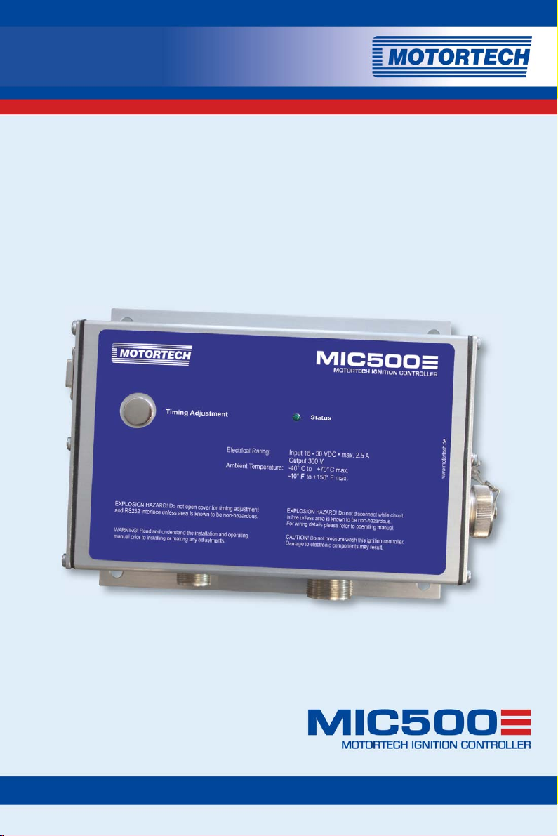
MIC500 –
IGNITION CONTROLLER
OPERATING MANUAL
MOTORTECH Ignition Controllers
P/N 01.10.0
0-EN | Rev. 01/201
Page 2

Copyright
© Copyright 2015 MOTORTECH GmbH. All rights reserved.
Distribution and reproduction of this publication or parts thereof, regardless of the specific
purpose and form, are not permissible without express written approval by MOTORTECH.
Information contained in this publication may be changed without prior notice.
Trademarks
All trademarks and logos displayed or used in this publication are the property of the respective
entitled person.
Page 3

S
TABLE OF CONTENT
1 General Information ..................................................................................................... 7
1.1 What Is the Purpose of this Operating Manual? ......................................................... 7
1.2 Who Is this Operating Manual Targeted to? ............................................................... 7
1.3 Which Symbols Are Used in the Operating Manual? ................................................... 7
1.4 Which Abbreviations/Acronyms Are Used in the Operating Manual? ........................... 8
2 Safety Instructions .................................................................................................... 10
2.1 General Safety Instructions ................................................................................... 10
2.2 Electrostatic Discharge Hazards ............................................................................. 11
2.3 Special Safety Instructions for the Device ............................................................... 11
2.4 Proper Disposal .................................................................................................... 13
3 Intended Use ............................................................................................................. 14
3.1 Functional Description .......................................................................................... 14
3.2 Applications ......................................................................................................... 14
4 Product Description ................................................................................................... 15
4.1 Product Overview .................................................................................................. 15
4.2 Technical Data...................................................................................................... 16
4.2.1 Certifications ..................................................................................................... 16
4.2.2 Mechanical Data ................................................................................................ 20
4.2.3 Warning Notices on the Device ........................................................................... 20
4.2.4 Product Identification – Labeling on the Device ................................................... 20
4.2.5 Electrical Data ................................................................................................... 21
4.2.6 Interfaces ......................................................................................................... 22
4.2.7 Requirements for External Equipment ................................................................. 22
4.2.8 Overview Drawings ............................................................................................ 23
5 Installation Instructions ............................................................................................ 26
5.1 Unpacking ............................................................................................................ 26
5.2 Determine the Installation Location of the Pickup and the Trigger Disc ..................... 26
5.3 Installation of the Ignition Controller ..................................................................... 27
6 Wiring of the Device .................................................................................................. 28
6.1 Input and Output Wiring on the Controller .............................................................. 28
6.1.1 Input and Output Connector – P/N 06.00.507, P/N 06.00.508 ............................... 29
6.1.2 Input and Output Connector – P/N 06.00.510 ....................................................... 30
6.1.3 Input and Output Connector – P/N 06.00.511 ....................................................... 32
6.1.4 Input and Output Connector – P/N 06.00.513 ....................................................... 34
6.1.5 Input and Output Connector – P/N 06.00.514 ....................................................... 36
Rev. 01/2015 3
Page 4

TABLE OF CONTENTS
6.1.6 Input and Output Connector – P/N 06.00.515-6 and -8 ......................................... 38
6.1.7 Input and Output Connector – P/N 06.00.516 ....................................................... 40
6.1.8 Input and Output Connector – P/N 06.00.517 ....................................................... 42
6.1.9 Input and Output Connector – P/N 06.00.520 ...................................................... 44
6.1.10 Input and Output Connector – P/N 06.00.525 ..................................................... 46
6.1.11 Input and Output Connector – P/N 06.00.530 ..................................................... 48
6.1.12 Input and Output Connector – P/N 06.00.550 ..................................................... 50
6.1.13 Input Wiring – Power Supply ............................................................................. 52
6.1.14 Input Wiring – 4-20 mA Input ............................................................................ 53
6.1.15 Input Wiring – Pickup ....................................................................................... 54
6.1.16 Wiring – Digital Input, Go/NoGo ........................................................................ 56
7 Functions ................................................................................................................... 57
7.1 Monitoring of Pickup Signal ................................................................................... 57
7.2 Go/NoGo ............................................................................................................. 57
7.3 Remote-Controlled Ignition Release ....................................................................... 58
7.4 Schedules A/B ..................................................................................................... 59
7.5 Timing Correction ................................................................................................. 60
7.5.1 Manual Timing Correction ................................................................................... 61
7.5.2 Analog Current Input – 4-20 mA .......................................................................... 62
7.5.3 Speed Curve ...................................................................................................... 62
7.5.4 Cylinder-to-Cylinder Alignment ........................................................................... 62
7.6 Misfire Detection .................................................................................................. 62
7.7 Ignition Energy ..................................................................................................... 63
8 Adjustments .............................................................................................................. 64
8.1 Ignition Control .................................................................................................... 64
8.1.1 System Requirements Ignition Control ................................................................. 64
8.1.2 Installing Ignition Control ................................................................................... 64
8.1.3 Starting Ignition Control ..................................................................................... 67
8.1.4 Menu Bar and Buttons ........................................................................................ 68
8.2 Hand-Held Programmer ........................................................................................ 69
8.2.1 RS232 Interface Adjustments ............................................................................. 69
8.2.2 Switching on the Hand-Held Programmer ............................................................ 70
8.2.3 Keys of the Control Panel .................................................................................... 71
8.3 Conventions Used in the Following ........................................................................ 72
8.4 Main View ............................................................................................................ 73
8.5 Parameterization Level ......................................................................................... 75
8.5.1 General Operation of the Parameterization Level ................................................. 75
4 Rev. 01/2015
Page 5

8.5.2 Brief Overview of Parameters ............................................................................. 78
8.5.3 Set Sequence Number ....................................................................................... 80
8.5.4 Set Reset Position ............................................................................................. 84
8.5.5 Set Overspeed ................................................................................................... 84
8.5.6 Set Security Speed ............................................................................................ 85
8.5.7 Set Misfire Rate ................................................................................................. 86
8.5.8 Activate Cylinder-to-Cylinder Alignment .............................................................. 87
8.5.9 Select Function for Digital Input .......................................................................... 87
8.5.10 Activate Potentiometer ..................................................................................... 88
8.5.11 Activate Functions for Schedules A and B ........................................................... 89
8.5.12 Set Potentiometer Limits .................................................................................. 91
8.5.13 Set Ignition Timing Limits ................................................................................. 93
8.5.14 Set Timing Offset for Schedule B ....................................................................... 95
8.5.15 Set Limits for 4-20 mA Input .............................................................................. 95
8.5.16 Set Speed Curve .............................................................................................. 97
8.5.17 Configuration Example ................................................................................... 100
8.6 Additional Functions .......................................................................................... 102
8.6.1 Set Ignition Energy .......................................................................................... 102
8.6.2 Information View ............................................................................................. 103
8.6.3 Cylinder-to-Cylinder Alignment ........................................................................ 103
8.6.4 Self Test ......................................................................................................... 105
8.6.5 Misfire Detection ............................................................................................. 107
8.7 Programming Overview ....................................................................................... 107
9 Operation ................................................................................................................ 110
9.1 Start-up .............................................................................................................. 110
9.2 Shutdown ........................................................................................................... 110
10 Errors ...................................................................................................................... 111
10.1 Possible Faults ................................................................................................... 111
10.2 Causes of Faults................................................................................................. 111
10.2.1 Overspeed ...................................................................................................... 111
10.2.2 Misfire Detection (Primary) .............................................................................. 111
10.2.3 Pickup Input Errors .......................................................................................... 112
10.2.4 Insufficient Power Supply ................................................................................ 112
10.2.5 Exiting Error Status ......................................................................................... 112
10.3 Troubleshooting and Eliminating Errors ............................................................... 113
10.3.1 Message and Error Overview ............................................................................ 113
10.3.2 Testing Supply Voltage .................................................................................... 114
Rev. 01/2015 5
Page 6

TABLE OF CONTENTS
10.3.3 Testing Pickup Signal ...................................................................................... 114
10.3.4 Running a Self Test ......................................................................................... 116
10.3.5 Customer Service Information .......................................................................... 117
10.3.6 Returning Equipment for Repair / Inspection .................................................... 117
10.3.7 Instructions for Packaging the Equipment ......................................................... 118
11 Maintenance ........................................................................................................... 119
11.1 Maintenance Instructions .................................................................................... 119
11.2 Spare Parts and Accessories ............................................................................... 119
12 Index ..................................................................................................................... 120
6 Rev. 01/2015
Page 7
1 GENERAL INFORMATION
Read through this operating manual carefully before use and become familiar with the machine.
Installation and start-up should not be carried out before reading and understanding this
document. Keep this manual readily available so that you can reference it as needed.
1.1 What Is the Purpose of this Operating Manual?
This manual serves as an aid for the installation and operation of the product and supports the
technical staff with all operating and maintenance tasks to be performed. Furthermore, this
manual is aimed at preventing dangers to life and health of the user and third parties.
1.2 Who Is this Operating Manual Targeted to?
The operating manual provides a code of conduct for personnel tasked with the set-up,
operation, maintenance, and repair of gas engines. A certain level of technical knowledge with
respect to the operation of gas engines and basic knowledge of electronic ignition systems are
necessary. Persons who are only authorized to operate the gas engine shall be trained by the
operating company and shall be expressly instructed concerning potential hazards.
1.3 Which Symbols Are Used in the Operating Manual?
The following symbols are used in this manual and must be observed:
Example
This symbol indicates examples, which point out necessary handling steps
and techniques. In addition, you receive additional information from the
examples, which will increase your knowledge.
Notice
This symbol indicates important notices for the user. Follow these. In
addition, this symbol is used for overviews that give you a summary of the
necessary work steps.
Warning
This symbol indicates warnings for possible risks of property damage or
risks to health. Read these warning notices carefully and take the
mentioned precautionary measures.
Rev. 01/2015 7
Page 8
1 GENERAL INFORMATION
Danger
This symbol indicates warnings for danger to life, especially due to high
voltage. Read these warning notices carefully and take the mentioned
precautionary measures.
1.4 Which Abbreviations/Acronyms Are Used in the Operating Manual?
In the manual or the user interface, the following abbreviations / acronyms are used:
Abb. Term Description Explanation
ADV Advance Advanced with respect
to top dead center
ATDC After Top Dead Center After top dead center
BTDC Before Top Dead
Center
CE Conformité
Européenne
°crank-
Degree crankshaft Unit for the rotation angle of
Before top dead
center
Conformity with EU
directives
shaft
CSA Canadian Standards
Association
DC Direct Current Direct current
EMC Electromagnetic
Compatibility
LED Light Emitting Diode Light emitting diode Light emitting electronic semi-
POT Potentiometer Continuously adjustable
PWR Power Output / current Operating voltage
RET Retard Retarded with respect
to the top dead center
Indicates the direction for
timing
Mark based on EU legislation
for certain products in
conjunction with product safety
the crankshaft
Organization that defines
standards, inspects products
for safety compliance, and
issues pertinent certifications.
Compatibility of electrical or
electronic equipment items
with their surroundings
conductor
potential divider
Indicates the direction for
timing
8 Rev. 01/2015
Page 9

Abb. Term Description Explanation
RPM Revolutions Per
Minute
Revolutions per
minute
Unit for speed
TDC Top Dead Center
Rev. 01/2015 9
Page 10
2 SAFETY INSTRUCTIONS
2.1 General Safety Instructions
The following safety instructions must be followed in the area in which the device is operated.
High voltage! Danger to life!
While the engine is running, the area around the ignition system especially
holds the risk of danger due to high voltage. The following parts should
therefore not be touched or removed unless explicitly stated otherwise:
– Ignition coils and caps
– Wires of the high voltage circuit
– In- and output wiring of the ignition controller
– Pickups and their wiring
Danger to persons with pacemakers!
Electromagnetic impulses in the wiring of the ignition system may exceed
the permissible limits of pacemakers. Persons with pacemakers must
MOTORTECH equipment is manufactured as state of the art and therefore safe and reliable to
operate. Nevertheless the equipment can cause risks or damages can occur, if the following
instructions are not complied with:
– The gas engine must only be operated by trained and authorized personnel.
– Operate the equipment only within the parameters specified in the technical data.
– Use the equipment correctly and for its intended use only.
– Never apply force.
– For all work, such as installation, conversion, adaptation, maintenance, and repair, all
equipment must be disconnected from the power supply and secured against unintentional
restarting.
– Perform only such maintenance and repair work as is described in this operating manual,
and follow the instructions given while working. For maintenance of the equipment, only use
spare parts supplied by MOTORTECH. Further work must only be performed by personnel
authorized by MOTORTECH. Non-compliance with the instructions will void any warranties
for the proper function of the equipment as well as the responsibility for the validity of the
certifications.
– Safety devices must not be dismounted or disabled.
– Avoid all activities that can impair the function of the equipment.
therefore not be present in the vicinity of the ignition system being
operated. Mark the operating location of the ignition system with the
corresponding standardized warning symbol.
10 Rev. 01/2015
Page 11

– Operate the equipment only while it is in proper condition.
– Investigate all changes detected while operating the gas engine or ignition system.
– Ensure compliance with all laws, directives and regulations applicable to the operation of
your system, including such not expressly stated herein.
– If the system is not entirely tight and sealed, gas may escape and lead to an explosion
hazard. Upon completion of all assembly works, always check the system's tightness.
– Always ensure adequate ventilation of the engine compartment.
– Ensure a safe position at the gas engine.
2.2 Electrostatic Discharge Hazards
Electronic equipment is sensitive to static electricity. To protect these components from damage
caused by static electricity, special precautions must be taken to minimize or prevent
electrostatic discharge.
Observe these safety precautions while you work with the equipment or in its vicinity.
– Before performing maintenance or repair work, ensure that the static electricity inherent to
your body is discharged.
– Do not wear clothing made from synthetic materials to prevent static electricity from
building up. Your clothing should therefore be made of cotton or cotton mix materials.
– Keep plastics such as vinyl and Styrofoam materials as far away from the control system, the
modules, and the work environment as possible.
– Do not remove the circuit boards from the housing of the device.
2.3 Special Safety Instructions for the Device
Danger to life! Hazardous residual voltage!
A dangerous level of residual voltage is present in the ignition system for up
to three minutes after stopping the ignition. Do not touch any components
of the ignition kit during this time.
Explosion hazard!
When the system is powered up, do not remove any connectors unless the
system is not located in a potentially explosive atmosphere.
Rev. 01/2015 11
Page 12

2 SAFETY INSTRUCTIONS
Explosion hazard!
The replacement of parts or assemblies can impair compliance with CSA
Class I, Division 2 (Group C, D), T4.
Explosion hazard!
Never remove the equipment while the device is connected to a power
source unless the system is not located in an explosive environment.
Risk of burning!
The surfaces of the system may heat up to high temperatures.
Operational safety!
All connector screws and screw joints must be adequately tightened.
Compliance with the following tightening torques is mandatory:
– RS232 connection: 1 Nm (0.7 lb-ft)
– Connection plug 6-pole, 7-pole, 10-pole: 2.6 Nm (1.9 lb-ft)
– Connection plug 14-pole, 19-pole: 5 Nm (3.7 lb-ft)
Explosion hazard!
Never remove the cover for timing adjustment and the RS232 interface,
unless the system is not located in an explosive environment.
12 Rev. 01/2015
Page 13

Risk of damage!
Magnetic fields and heat occur when welding, which may damage or
destroy the MIC500. Therefore, pay attention to the following when
welding:
– Disconnect all electrical connections to the MIC500 prior to welding.
– Protect the MIC500 against direct contact with the welding unit and
magnetic fields, sparks and liquid metal.
2.4 Proper Disposal
After the expiration of its service life, MOTORTECH equipment can be disposed of with other
commercial waste, or it may be returned to MOTORTECH. We will ensure its environmentally
friendly disposal.
Rev. 01/2015 13
Page 14

3
INTENDED USE
3.1 Functional Description
The devices of the MIC500 series are microprocessor-controlled condenser discharge ignition
systems, which provide the ignition energy for gas engines with up to 16 cylinders.
Please note that the manufacturer is not required to implement configurations of the ignition
controller for specific engines, and that devices may be delivered without pertinent
configuration.
The ignition controllers of the MIC500 series use information supplied by the pickup to precisely
determine the correct timing for the respective outputs. An event type N+1 trigger disc serves as
transmitter.
The timing is influenced by various inputs made either automatically or manually. This can be
implemented with the installed manual potentiometer, an analog input signal (4-20 mA) or a
configurable speed curve.
By checking the information received, the ignition controllers continuously monitor the system
status of the pickup and the correct operation of the primary ignition circuit during operation.
Depending on the severity of an error that is detected, the devices will shut down immediately or
warn the operator by a flashing LED.
To protect the engine, the ignition controllers additionally have an adjustable overspeed shutoff.
3.2 Applications
Depending on the device type, the ignition controllers of the MIC500 series are designed for
specific 2- or 4-stroke gas engines. Depending on the device type, there are between 2 to max.
16 ignition outputs available.
The ignition controllers supply the energy output required for the corresponding ignition coils of
the gas engines and can supply signals for peripheral devices. Any use other than the one
described in the operating manual shall be considered improper use and will result in the
voiding of all warranties.
14 Rev. 01/2015
Page 15
4
PRODUCT DESCRIPTION
4.1 Product Overview
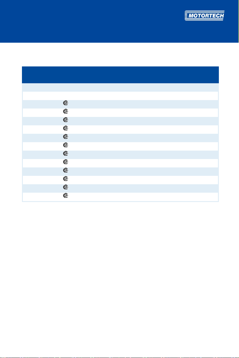
The following properties of the devices from the MIC500 series differ as follows:
Device type
P/N 06.00.507 8 30 V DC 24VDC
P/N 06.00.508 8 30 V DC 24 V DC
P/N 06.00.510 16 30 V DC 24VDC
P/N 06.00.511 16 30V DC 24VDC
P/N 06.00.513 8 300 V DC 8V DC
P/N 06.00.514 16 30 V DC 8 V DC
P/N 06.00.515-6 8 (programmed on 6) 300 V DC 8VDC
P/N 06.00.515-8 8 300 V DC 8 V DC
P/N 06.00.516 16 (programmed on 12) 300 V DC 8VDC
P/N 06.00.517 16 300 V DC 8 V DC
P/N 06.00.520 8 300 V DC 24VDC
P/N 06.00.525 12 300 V DC 24 V DC
P/N 06.00.530 16 300 V DC 24VDC
P/N 06.00.550 8 30V DC 24VDC
Number of outputs
Test port /
monitor voltage
Voltage for pickup
Rev. 01/2015 15
Page 16

4 PRODUCT DESCRIPTION
4.2 Technical Data
4.2.1 Certifications
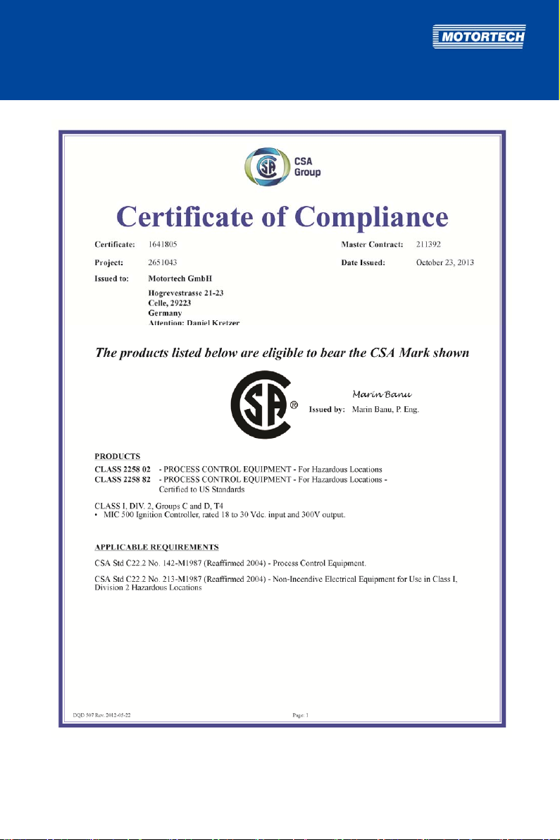
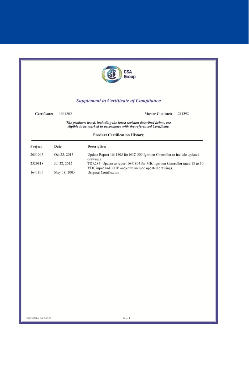
The ignition controllers of the MIC500 series with the test mark are certified as per the
following CSA standards:
CSA
– Class I, Division 2, Group C and D, T4
– CSA Std C22.2 No. 142-M1987 (Reaffirmed 2004)
– CSA Std C22.2 No. 213-M1987 (Reaffirmed 2004)
The ignition controllers of the MIC500 series are additionally certified as per the following
directives/regulations:
CE
– EMC Directive 2004/108/EC
– Limits as per DIN EN 55011:2011
– Immunity for industrial environments as per DIN EN 61000-6-2:2006-03
– Emission standard for industrial environments as per DIN EN 61000-6-4:2007-09
– Low Voltage Directive 2006/95/EC
– Low voltage switchgear – General rules as per DIN EN 60947-1:2007
16 Rev. 01/2015
Page 17
Rev. 01/2015 17
Page 18
4 PRODUCT DESCRIPTION
18 Rev. 01/2015
Page 19

x
DECLARATION OF CONFORMITY
The Company:
declares that the products: Ignition controller MIC500
Intended purpose: to be used on gas-Otto-engines
complies with the provisions of the following EC Directives:
under consideration of following standards:
The marking of the product is: P/N 06.00.5x
This declaration is submitted by:
Name: Florian Virchow
MOTORTECH GmbH
Hogrevestrasse 21 - 23
29223 Celle
EMC Directive 2004/108/EC
Low Voltage Directive 2006/95/EC
DIN EN 55011-2011
DIN EN 61000-6-2-2006:03
DIN EN 61000-6-4-2007:09
DIN EN 60947-1 : 2007
Professional status: Managing Director
Celle, 13.07.2011
City, date
Rev. 01/2015 19
legally binding signature
Page 20
4 PRODUCT DESCRIPTION
4.2.2 Mechanical Data
The devices of the MIC500 series have the following mechanical characteristics:
Feature Value
Dimensions see chapter Overview Drawings on page 23
Weight 2.1 kg (4.7 lbs)
Shape of device see chapter Overview Drawings on page 23
Climatic environmental
conditions
4.2.3 Warning Notices on the Device
EXPLOSION HAZARD! Do not open cover for timing adjustment and RS232 interface unless area is
known to be non-hazardous.
WARNING! Read and understand the installation and operating manual prior to installing or
making any adjustments.
EXPLOSION HAZARD! Do not disconnect while circuit is live unless area is known to be nonhazardous. For wiring details please refer to the operating manual.
CAUTION! Do not pressure wash this ignition module. Damage to electronic components may
result.
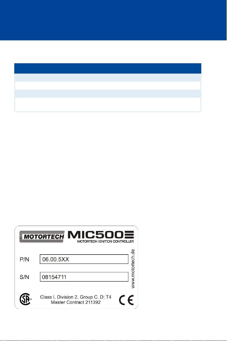
4.2.4 Product Identification – Labeling on the Device
The necessary numbers for unique product identification are on the device:
– P/N: Product number of the ignition controller
– S/N: Serial number of the ignition controller
-40°C to +70°C (-40°F to +158°F)
20 Rev. 01/2015
Page 21

4.2.5 Electrical Data
The devices of the MIC500 series have the following electrical characteristics:
Feature Value
Power consumption 60 W with 24 V
Power supply 18 V DC to 30 V DC
Required current Peak current 20 A
External fuse 6 A, slow blow
Number of ignition
outputs
Output voltage and
output energy
Output connector Depending on device type (see Input and Output Wiring on the
Electrical Data for Inputs and Outputs
The inputs and outputs of the MIC500 ignition controllers have the following electrical data:
Inputs and outputs Values
4-20 mA input Auxiliary voltage: Corresponds to supply voltage of the MIC500
Digital input Impedance: 10 kΩ
Go/NoGo output Switching capacity: 100 mA
Signal LED An LED to display operating mode and errors
Pickup input Impedance: 10 k
Continuous current 5 A
Depending on device type 8, 12 or 16 outputs (see Product
Overview on page 15)
Max. 180 mJ with 300 V
The output energy is adjustable from 15 % to 100 %.
Controller on page 28)
Open: 0 V to 0.8 V
Closed: 2.8 V to 30 V
Open collector output
Darlington-Transistor design
Voltage applied: 18 V DC to 30 V DC
Peak/steady current: max. 0.45 A DC
Output power: max. 2.4 W
Power supply for inductive pickups is based on the input voltage
e. g. 24 V DC with an input voltage of 24 V DC (see Product
Overview on page 15).
Rev. 01/2015 21
Page 22

4 PRODUCT DESCRIPTION
Inputs and outputs Values
Ignition coil outputs Output voltage: Max. 300 V
Output energy: Max. 180 mJ
Test ports /
monitor voltage
4.2.6 Interfaces
RS232
– VT100-Terminal
– Baud rate: 9,600, data bits: 8, stop bit: 1, parity: none
– Plug connection: D-SUB, 9-pole
– Maximum lead length: 5 m
4.2.7 Requirements for External Equipment
External equipment shall fulfill the input and output specifications of the MIC500.
Depending on device type (see Product Overviewon page 15)
22 Rev. 01/2015
Page 23
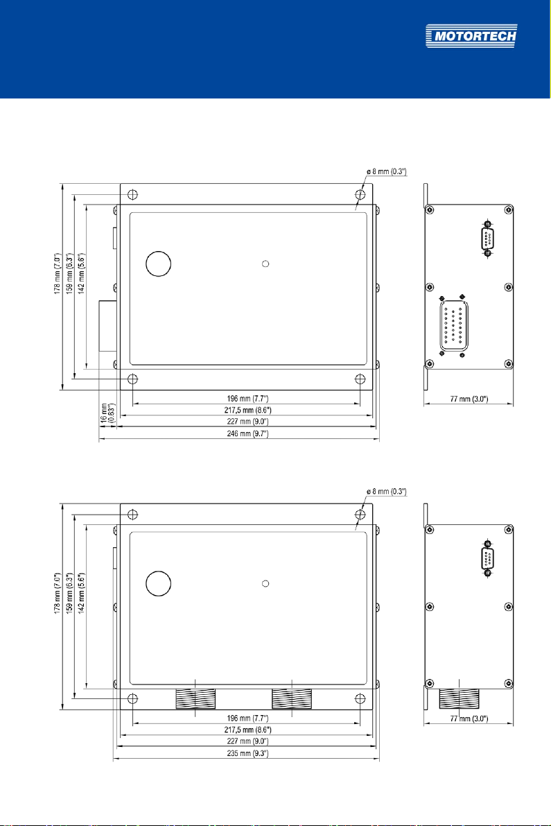
4.2.8 Overview Drawings
P/N 06.00.507, P/N 06.00.508:
P/N 06.00.511, P/N 06.00.520, P/N 06.00.525, P/N 06.00.530, P/N 06.00.550:
Rev. 01/2015 23
Page 24

4 PRODUCT DESCRIPTION
P/N 06.00.513, P/N 06.00.514, P/N 06.00.515-6 and -8, P/N 06.00.516, P/N 06.00.517:
All device types:
24 Rev. 01/2015
Page 25
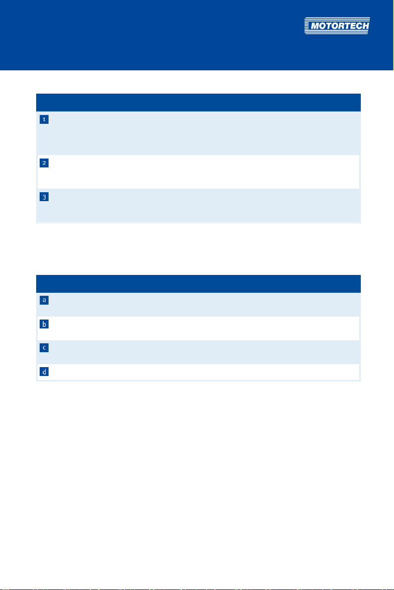
Device Components
Pos. Labeling Description Function
Timing adjustment potentiometer Potentiometer for manual timing
Status Status LED LED for displaying operating mode and
Inputs and Outputs Based on Device Type
The connections for the input and output wiring vary between the device types. For detailed
information, see section Input and Output Wiring on the Controller on page 28.
Pos. Connection position Function
Left side of device Input and output connection, 23-pole (depending on device
Left front Input and output connection, 6-, 7-, or 10-pole (depending on
Right front Input and output connection, 10-, 14-, or 19-pole (depending
Right side of device Input connection, 10-pole (depending on device type)
RS232 connection Connection of the ignition controller to a
computer or a hand-held programmer for
configuration and status monitoring (see
Adjustments on page 64).
adjustment (see Manual Timing Correction
on page 61).
error conditions (see Message and Error
Overview on page 113)
type)
device type)
on device type)
Rev. 01/2015 25
Page 26

5
INSTALLATION INSTRUCTIONS
5.1 Unpacking
Unpack the device, taking care not to damage it, and ensure that the operating manual is always
stored with the ignition controller and is easily accessible. Check the contents for completeness
and verify that the device type meets your application requirements.
Scope of Supply
The scope of supply of the MIC500 ignition controllers consists of the following components:
– Ignition controller MIC500
– Installation set incl. four vibration dampers
– Ground strap
– Storage device (USB flash drive or CD-ROM) with software for configuring the ignition
controller
– RS232 interface cable for connecting the ignition controller with a PC/laptop or hand-held
programmer
– Operating manual
5.2 Determine the Installation Location of the Pickup and the Trigger Disc
Depending on engine type and application, the position of the pickup must be specified. All
angle reference information is based on:
TDC 1st cylinder / Compression cycle
The installation location for the pickup must have adequate mechanical strength and must not
exceed the specified temperature ranges. The pickup is designed for its appropriate use only,
multiple use of the pickup signal is not permissible. The N+1 triggering can be carried out via the
crankshaft or the camshaft. Ensure good accessibility to facilitate the calibration of the pickup.
Comply with the pertinent regulations for the wire routing.
The precise position of the pickup is shown in the example in chapter Input Wiring – Pickup on
page 54.
26 Rev. 01/2015
Page 27

5.3 Installation of the Ignition Controller
Risk of damage!
The device must not be installed directly on or at the engine, as vibration
and heat may cause damage to electronic components.
The installation of the MIC500 ignition controller is implemented on a fixed bracket or a wall
near the engine. Always use the included vibration dampers and the ground strap. The
installation location of the device must be selected so that the distance to the pickup installed
on the engine ensures a reliable signal transmission to the ignition controller, and so that there
is adequate space for maintenance and repair work. Also ensure adequate space for the
connection wiring. The mechanical specifications must be complied with. The ground strap
serves to ground the ignition controller and must be used accordingly. Ensure a flawless
electrical connection for this purpose.
Installation locations where strong vibrations or ambient temperatures of below -40 °C (-40 °F)
or above +70 °C (+158 °F) are present are not permissible and result in the warranty being
voided.
Rev. 01/2015 27
Page 28
6 WIRING OF THE DEVICE
6.1 Input and Output Wiring on the Controller
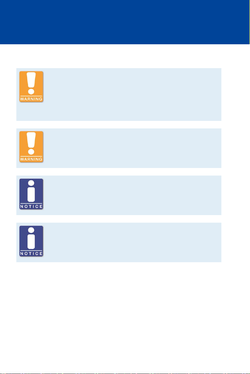
Operational safety!
All connector screws and screw joints must be adequately tightened.
Compliance with the following tightening torques is mandatory:
– RS232 connection: 1 Nm (0.7 lb-ft)
– Connection plug 6-pole, 7-pole, 10-pole: 2.6 Nm (1.9 lb-ft)
– Connection plug 14-pole, 19-pole: 5 Nm (3.7 lb-ft)
Operational safety!
Never connect more than one output to each ignition coil, as the output
boards can otherwise be damaged!
Assignment of the wire colors
Take the assignment of the wire colors of the wiring harness for the input
and output wiring from the wiring plan enclosed with the wiring harness.
Protection when using wiring rails
Every wiring rail on the engine block should be grounded to avoid
disruptions in the device caused by secondary current in the ignition coils.
28 Rev. 01/2015
Page 29
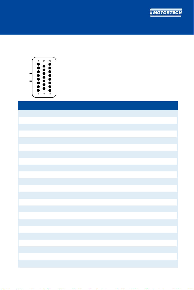
6.1.1 Input and Output Connector – P/N 06.00.507, P/N 06.00.508
Input and output connector: left side of device, 23-pole, connector
Pin Pin assignment
1 Ignition output D
2 Ignition output C
3 Ignition output B
4 Ignition output A
5 Switch Go/NoGo
6 Not used
7 (+) 4-20 mA
8 Pickup signal
9 Ignition output E
10 Ground
11 Measuring lead (1:10)
12 (-) Supply voltage
13 (+) Supply voltage
14 Supply voltage pickup (24 V DC)
15 (-) 4-20 mA
16 Ignition output F
17 Ignition output K
18 Ignition output L
19 Digital input (Switch A/B or Switch Start/Stop)
20 Not used
21 Not used
22 4-20 mA PWR
23 Pickup ground
Rev. 01/2015 29
Page 30
6 WIRING OF THE DEVICE
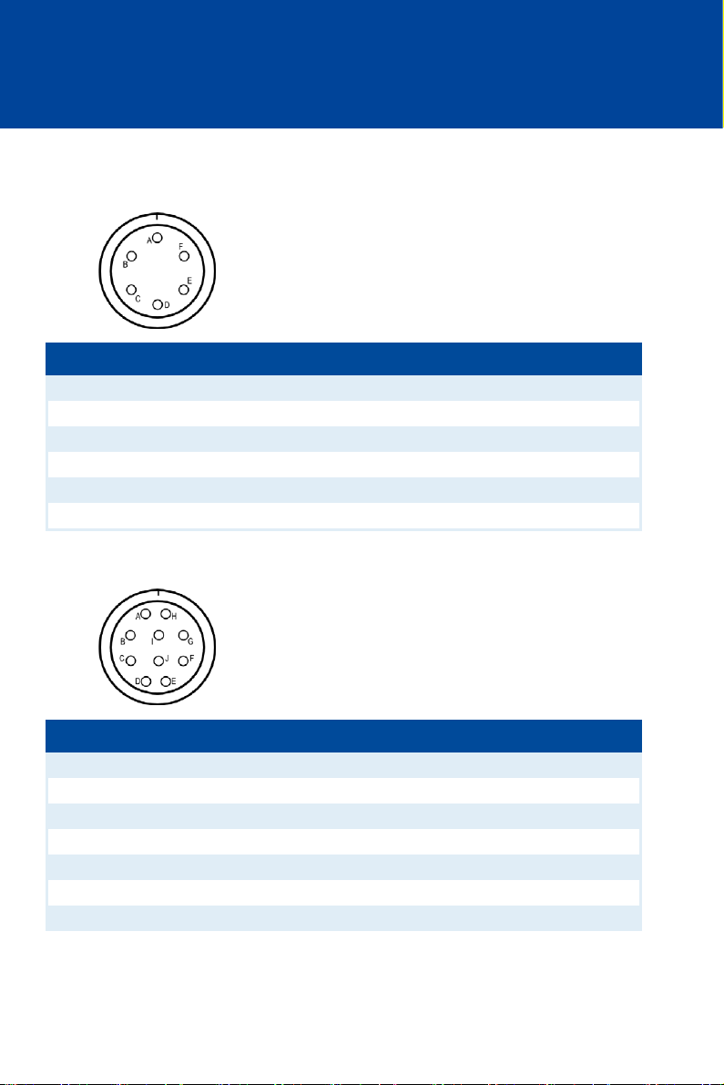
6.1.2 Input and Output Connector – P/N 06.00.510
Input connector: left front, 6-pole, socket
Pole Pole assignment
A Pickup signal
B Supply voltage pickup (24 V DC)
C Pickup ground
D Switch Go/NoGo
E (+) Supply voltage
F (-) Supply voltage
right side of device, 10-pole, socket
Pole Pole assignment
A Not used
B Not used
C (+) 4-20 mA
D Digital input (Switch A/B or Switch Start/Stop)
E (-) 4-20 mA
F 4-20 mA PWR
G Not used
30 Rev. 01/2015
Page 31
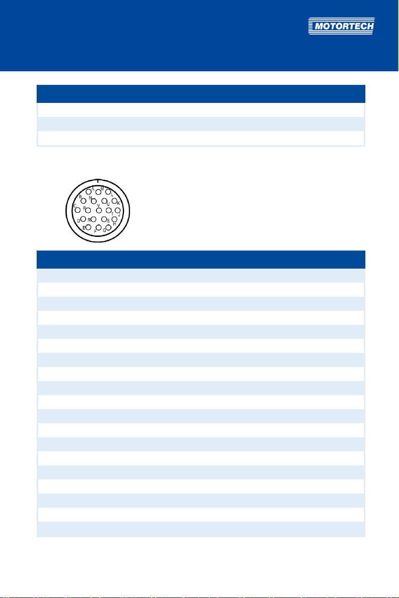
Pole Pole assignment
H Not used
I Not used
J Not used
Output connector: right front, 19-pole, socket
Pole Pole assignment
A Ignition output A
B Ignition output B
C Ignition output C
D Ignition output D
E Ignition output E
F Ignition output F
G Measuring lead (1:1)
H Measuring lead (1:10)
J Ground
K Ignition output K
L Ignition output L
M Ignition output M
N Ignition output N
P Ignition output P
R Ignition output R
S Ignition output S
T Ignition output T
U Ignition output U
V Ignition output V
Rev. 01/2015 31
Page 32

6 WIRING OF THE DEVICE
6.1.3 Input and Output Connector – P/N 06.00.511
Input connector: left front, 10-pole, socket
Pole Pole assignment
A (+) Supply voltage
B (-) Supply voltage
C (+) 4-20 mA
D Digital input (Switch A/B or Switch Start/Stop)
E (-) 4-20 mA
F 4-20 mA PWR
G Pickup signal
H Supply voltage pickup (24 V DC)
I Pickup ground
J Switch Go/NoGo
32 Rev. 01/2015
Page 33

Output connector: right front, 19-pole, socket
Pole Pole assignment
A Ignition output A
B Ignition output B
C Ignition output C
D Ignition output D
E Ignition output E
F Ignition output F
G Measuring lead (1:1)
H Measuring lead (1:10)
J Ground
K Ignition output K
L Ignition output L
M Ignition output M
N Ignition output N
P Ignition output P
R Ignition output R
S Ignition output S
T Ignition output T
U Ignition output U
V Ignition output V
Rev. 01/2015 33
Page 34
6 WIRING OF THE DEVICE
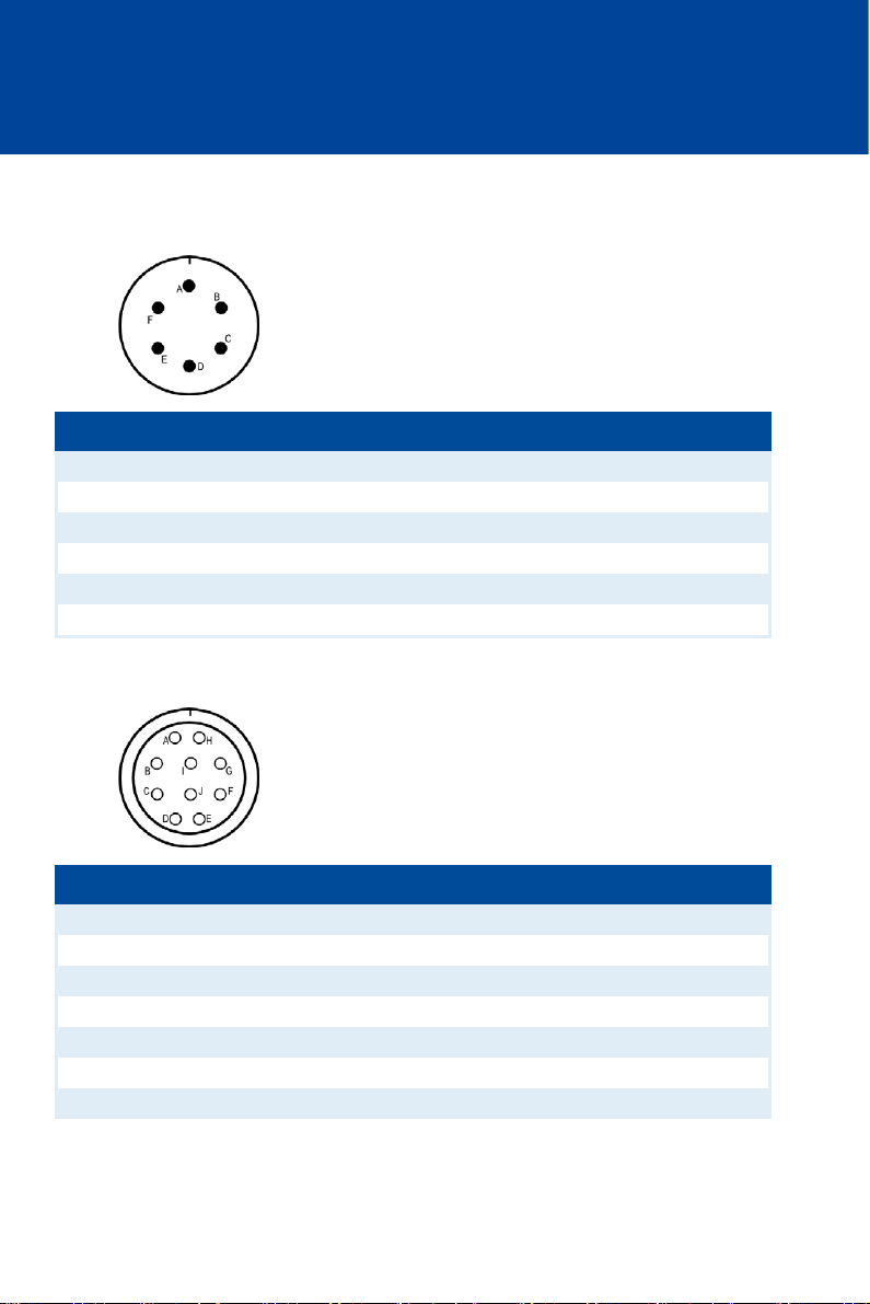
6.1.4 Input and Output Connector – P/N 06.00.513
Input connector: left front, 6-pole, connector
Pin Pin assignment
A Pickup signal
B Supply voltage pickup (8 V DC)
C Pickup ground
D Switch Go/NoGo
E (+) Supply voltage
F (-) Supply voltage
right side of device, 10-pole, socket
Pole Pole assignment
A Not used
B Not used
C (+) 4-20 mA
D Not used
E (-) 4-20 mA
F 4-20 mA PWR
G Not used
34 Rev. 01/2015
Page 35
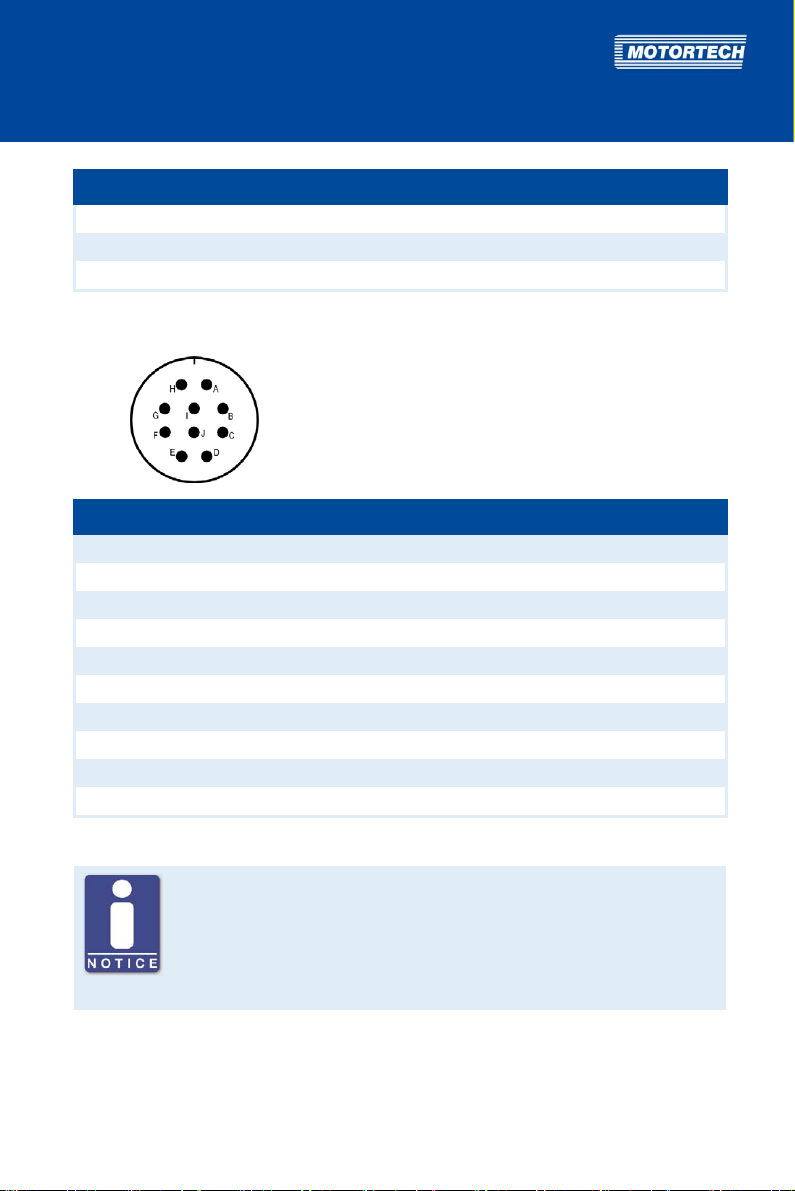
Pole Pole assignment
H Not used
I Not used
J Not used
Output connector: right front, 10-pole, connector
Pin Pin assignment
A Ignition output A
B Ignition output B
C Ignition output C
D Ignition output D
E Ignition output E
F Ignition output F
G Measuring lead (1:1)
H Ignition output K
I Ignition output L
J Ground
No digital input at P/N 06.00.513
The device type P/N 06.00.513 is designed as a replacement for the ignition
controller Caterpillar® 163-6164. Thus, the device does not have the digital
input (Switch A/B, Switch Start/Stop) as described in this operating manual.
With this device type, schedule A settings are applied solely for ignition
timing configuration.
Rev. 01/2015 35
Page 36
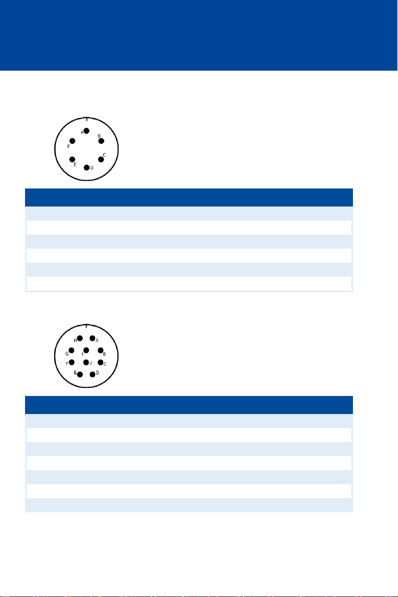
6 WIRING OF THE DEVICE
6.1.5 Input and Output Connector – P/N 06.00.514
Input connector: left front, 6-pole, connector
Pin Pin assignment
A Pickup signal
B Supply voltage pickup (8 V DC)
C Pickup ground
D Switch Go/NoGo
E (+) Supply voltage
F (-) Supply voltage
right side of device, 10-pole, connector
Pin Pin assignment
A Not used
B Not used
C (+) 4-20 mA
D Digital input (Switch A/B or Switch Start/Stop)
E (-) 4-20 mA
F 4-20 mA PWR
G Not used
36 Rev. 01/2015
Page 37
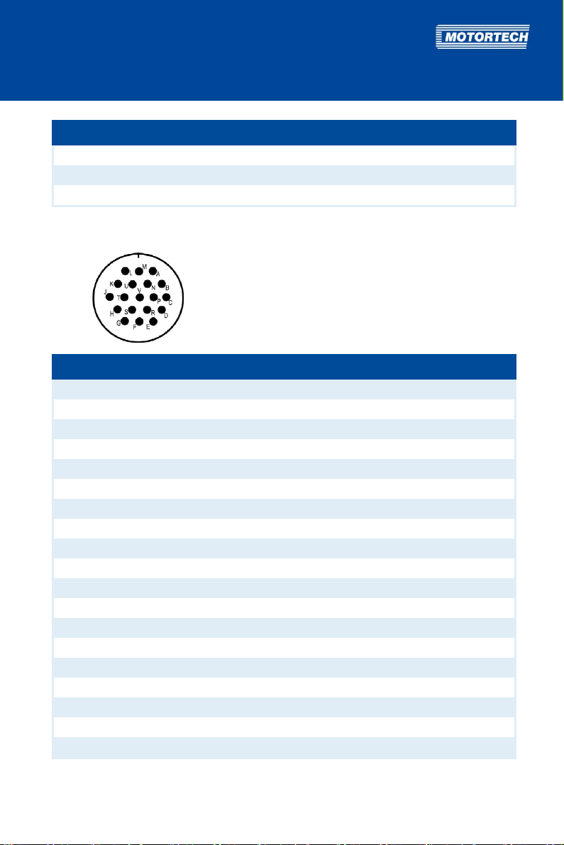
Pin Pin assignment
H Not used
I Not used
J Not used
Output connector: right front, 19-pole, connector
Pin Pin assignment
A Ignition output A
B Ignition output B
C Ignition output C
D Ignition output D
E Ignition output E
F Ignition output F
G Measuring lead (1:1)
H Measuring lead (1:10)
J Ground
K Ignition output K
L Ignition output L
M Ignition output M
N Ignition output N
P Ignition output P
R Ignition output R
S Ignition output S
T Ignition output T
U Ignition output U
V Ignition output V
Rev. 01/2015 37
Page 38
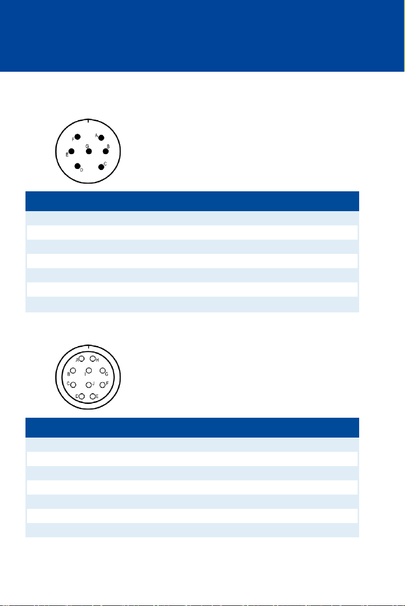
6 WIRING OF THE DEVICE
6.1.6 Input and Output Connector – P/N 06.00.515-6 and -8
Input connector: left front, 7-pole, connector
Pin Pin assignment
A Pickup signal
B Supply voltage pickup (8 V DC)
C Pickup ground
D Digital input (Switch A/B or Switch Start/Stop)
E (+) Supply voltage
F (-) Supply voltage
G Switch Go/NoGo
right side of device, 10-pole, socket
Pole Pole assignment
A Not used
B Not used
C (+) 4-20 mA
D Ground inputs
E (-) 4-20 mA
F 4-20 mA PWR
G Not used
38 Rev. 01/2015
Page 39
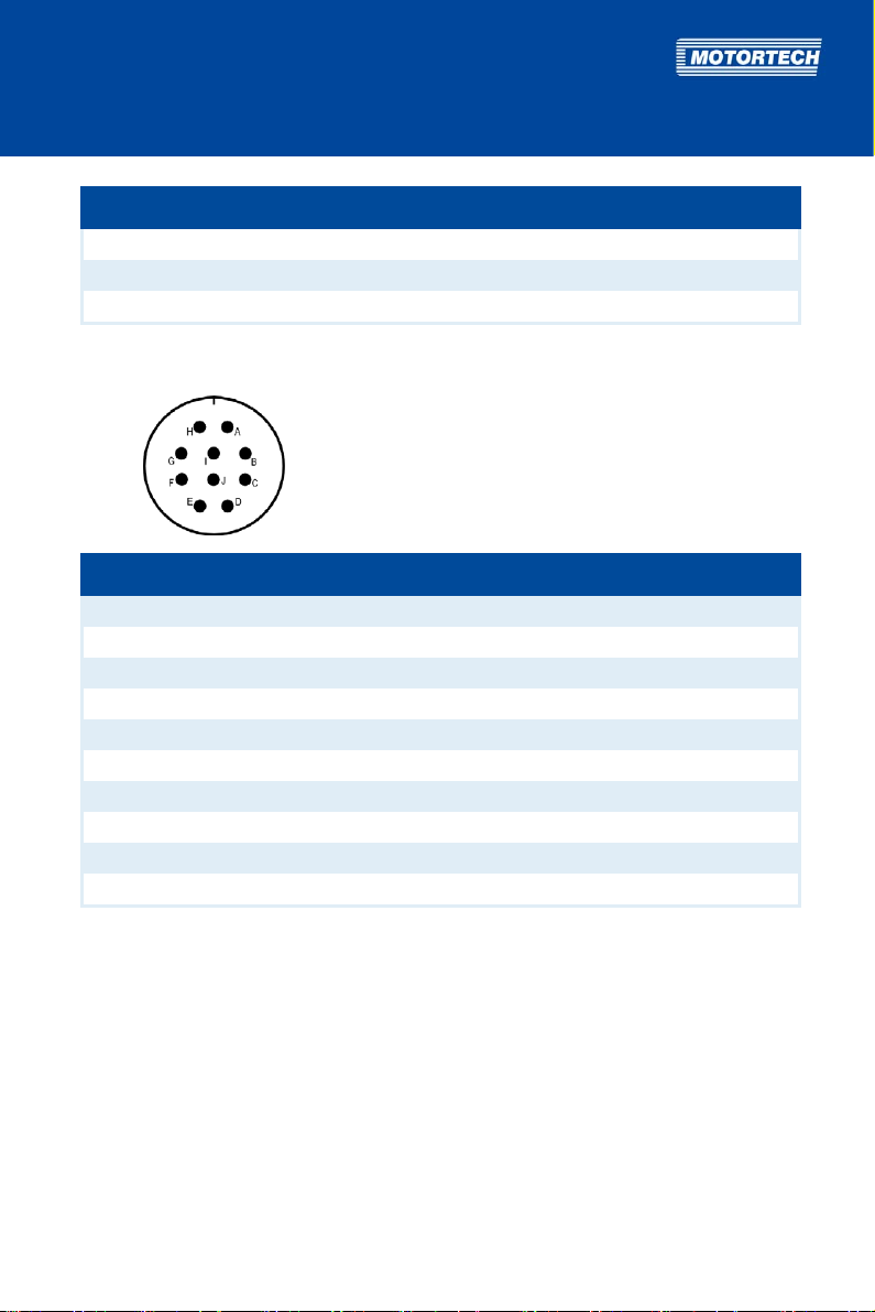
Pole Pole assignment
H Not used
I Not used
J Not used
Output connector: right front, 10-pole, connector
Pin Pin assignment
A Ignition output A
B Ignition output B
C Ignition output C
D Ignition output D
E Ignition output E
F Ignition output F
G Measuring lead (1:1)
H Ignition output K
I Ignition output L
J Ground
Rev. 01/2015 39
Page 40
6 WIRING OF THE DEVICE
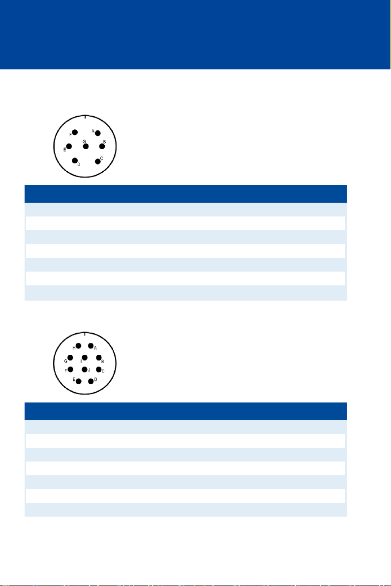
6.1.7 Input and Output Connector – P/N 06.00.516
Input connector: left front, 7-pole, connector
Pin Pin assignment
A Pickup signal
B Supply voltage pickup (8 V DC)
C Pickup ground
D Digital input (Switch A/B or Switch Start/Stop)
E (+) Supply voltage
F (-) Supply voltage
G Switch Go/NoGo
right side of device, 10-pole, connector
Pin Pin assignment
A Not used
B Not used
C (+) 4-20 mA
D Ground inputs
E (-) 4-20 mA
F 4-20 mA PWR
G Not used
40 Rev. 01/2015
Page 41
Pin Pin assignment
H Not used
I Not used
J Not used
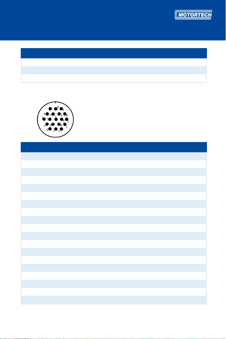
Output connector: right front, 19-pole, connector
Pin Pin assignment
A Ignition output A
B Ignition output B
C Ignition output C
D Ignition output D
E Ignition output E
F Ignition output F
G Measuring lead (1:1)
H Not used
J Ground
K Ignition output K
L Ignition output L
M Ignition output M
N Ignition output N
P Ignition output P
R Ignition output R
S Ignition output S
T Ignition output T
U Ignition output U
V Ignition output V
Rev. 01/2015 41
Page 42
6 WIRING OF THE DEVICE
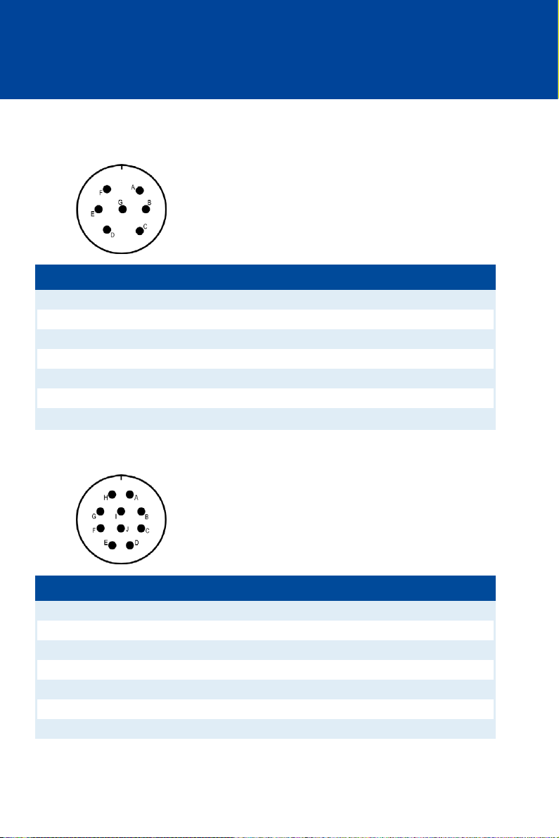
6.1.8 Input and Output Connector – P/N 06.00.517
Input connector: left front, 7-pole, connector
Pin Pin assignment
A Pickup signal
B Supply voltage pickup (8 V DC)
C Pickup ground
D Digital input (Switch A/B or Switch Start/Stop)
E (+) Supply voltage
F (-) Supply voltage
G Switch Go/NoGo
right side of device, 10-pole, connector
Pin Pin assignment
A Not used
B Not used
C (+) 4-20 mA
D Ground inputs
E (-) 4-20 mA
F 4-20 mA PWR
G Not used
42 Rev. 01/2015
Page 43
Pin Pin assignment
H Not used
I Not used
J Not used
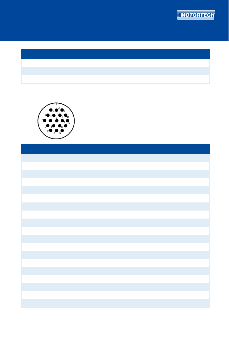
Output connector: right front, 19-pole, connector
Pin Pin assignment
A Ignition output V
B Ignition output A
C Ignition output B
D Ignition output C
E Ignition output D
F Ignition output E
G Measuring lead (1:1)
H Not used
J Ground
K Ignition output F
L Ignition output K
M Ignition output L
N Ignition output M
P Ignition output N
R Ignition output P
S Ignition output R
T Ignition output S
U Ignition output T
V Ignition output U
Rev. 01/2015 43
Page 44

6 WIRING OF THE DEVICE
6.1.9 Input and Output Connector – P/N 06.00.520
Input connector: left front, 10-pole, connector
Pin Pin assignment
A (+) Supply voltage
B (-) Supply voltage
C (+) 4-20 mA
D Digital input (Switch A/B or Switch Start/Stop)
E (-) 4-20 mA
F 4-20 mA PWR
G Pickup signal
H Supply voltage pickup (24 V DC)
I Pickup ground
J Switch Go/NoGo
44 Rev. 01/2015
Page 45

Output connector: right front, 10-pole, socket
Pole Pole assignment
A Ignition output A
B Ignition output B
C Ignition output C
D Ignition output D
E Ignition output E
F Ignition output F
G Ignition output K
H Measuring lead (1:1)
I Ignition output L
J Ground
Rev. 01/2015 45
Page 46

6 WIRING OF THE DEVICE
6.1.10 Input and Output Connector – P/N 06.00.525
Input connector: left front, 10-pole, connector
Pin Pin assignment
A (+) Supply voltage
B (-) Supply voltage
C (+) 4-20 mA
D Digital input (Switch A/B or Switch Start/Stop)
E (-) 4-20 mA
F 4-20 mA PWR
G Pickup signal
H Supply voltage pickup (24 V DC)
I Pickup ground
J Switch Go/NoGo
46 Rev. 01/2015
Page 47

Output connector: right front, 14-pole, socket
Pole Pole assignment
A Ignition output A
B Ignition output B
C Ignition output C
D Ignition output D
E Ignition output E
F Ignition output F
G Ignition output K
H Measuring lead (1:1)
I Ignition output L
J Ground
K Ignition output M
L Ignition output N
M Ignition output P
N Ignition output R
Rev. 01/2015 47
Page 48

6 WIRING OF THE DEVICE
6.1.11 Input and Output Connector – P/N 06.00.530
Input connector: left front, 10-pole, connector
Pin Pin assignment
A (+) Supply voltage
B (-) Supply voltage
C (+) 4-20 mA
D Digital input (Switch A/B or Switch Start/Stop)
E (-) 4-20 mA
F 4-20 mA PWR
G Pickup signal
H Supply voltage pickup (24 V DC)
I Pickup ground
J Switch Go/NoGo
48 Rev. 01/2015
Page 49

Output connector: right front, 19-pole, socket
Pole Pole assignment
A Ignition output A
B Ignition output B
C Ignition output C
D Ignition output D
E Ignition output E
F Ignition output F
G Ignition output K
H Measuring lead (1:1)
J Ground
K Ignition output L
L Ignition output M
M Ignition output N
N Ignition output P
P Ignition output R
R Ignition output S
S Ignition output T
T Ignition output U
U Ignition output V
V Not used
Rev. 01/2015 49
Page 50

6 WIRING OF THE DEVICE
6.1.12 Input and Output Connector – P/N 06.00.550
Input connector: right front, 14-pole, socket
Pole Pole assignment
A Pickup signal
B Pickup ground
C Not used
D Not used
E Not used
F (+) 4-20 mA
G (-) 4-20 mA
H Switch Go/NoGo
I Supply voltage pickup (24 V DC)
J Digital input (Switch A/B or Switch Start/Stop)
K (+) Supply voltage
L (-) Supply voltage
M Not used
N Not used
50 Rev. 01/2015
Page 51

Output connector: left front, 10-pole, socket
Pole Pole assignment
A Ignition output A
B Ignition output B
C Ignition output C
D Ignition output D
E Ignition output E
F Ignition output F
G Ignition output K
H Ignition output L
I Ground
J Measuring lead (1:1)
Rev. 01/2015 51
Page 52
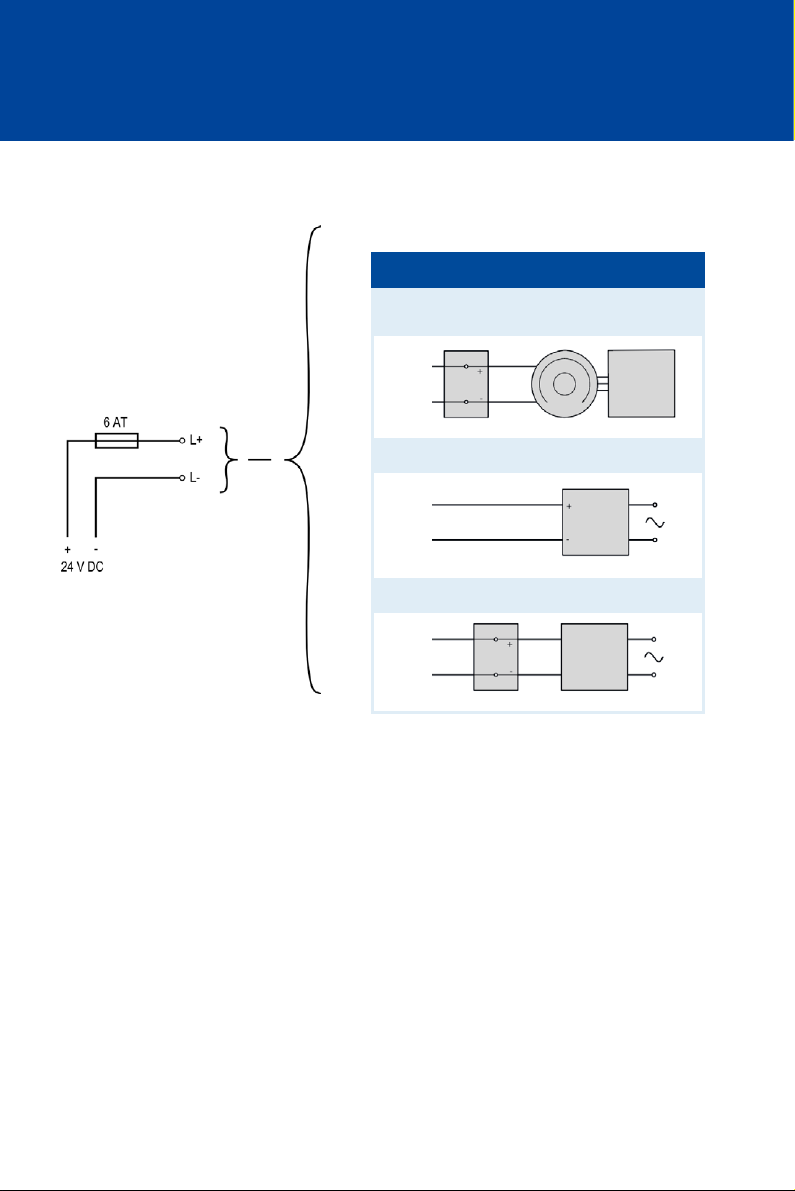
6 WIRING OF THE DEVICE
6.1.13 Input Wiring – Power Supply
Variations
1 Battery Generator Control
2
3
Battery Charger
Power Supply
Unit
52 Rev. 01/2015
Page 53
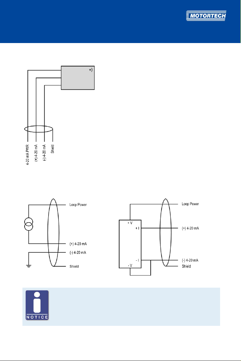
6.1.14 Input Wiring – 4-20 mA Input
)
See subsequent drawings for details
*
If wiring yourself, put the shield on the connector housing.
Two-wire transmitter
Four-wire transmitter
Auxiliary supply voltage for the 4-20 mA input
Via the 4-20 mA PWR terminal, the MIC500 series provides an auxiliary
supply voltage for the 4-20 mA input. If using current transmitters, the
4-20 mA PWR terminal is used for Loop Power.
Rev. 01/2015 53
Page 54
6 WIRING OF THE DEVICE
No 4-20 mA PWR terminal on P/N 06.00.550
The device type P/N 06.00.550 does not have a 4-20 mA PWR terminal.
Thus, this device type does not provide an auxiliary supply voltage for the
4-20 mA input.
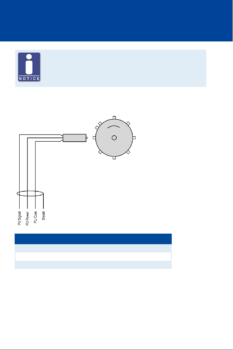
6.1.15 Input Wiring – Pickup
Example configuration (one active pickup with 8+1 trigger disc)
Designation Meaning
PU Signal Pickup signal
PU Power Supply voltage for pickup
PU Com Pickup ground
If wiring yourself, put the shield on the connector housing.
Connect passive (magnetic) pickup with plus to PU Signal and with minus to PU Com.
The recommended distance to the triggering is 0.75 mm to 1 mm (0.03" to 0.04") for MOTORTECH
pickups. Please note that additional fine-tuning is required for every pickup position due to the
different conditions of the engines.
54 Rev. 01/2015
Page 55
One revolution of the pickup changes the distance as follows:
Thread Change in distance
M12x1 1 revolution ≙ 1 mm (0.04'')
5/8"-18 UNF 1 revolution ≙ 1.41 mm (0.05'')
3/4"-16 UNF 1 revolution ≙ 1.59 mm (0.06'')
For problems with the pickup signal, see section Pickup Input Errors on page 112.
Auxiliary pickup supply voltage
Depending on the device type, the terminal PU Power provides an auxiliary
supply voltage of 8 V DC or 24 V DC for the pickup. You will find an overview
in the section Product Overview on page 15.
Triggering information
Observe the following when configuring the triggering:
– The maximum tightening torque for the counter nut is 15 Nm (11 lb-ft) for
all pickups.
– Ensure that the pickup fits the respective triggering:
Pickup Type of triggering
Magnetic Holes, pins, screws, teeth, slots
Inductive Pins, screws, slots, holes (as of 8 mm
diameter)
Hall effect Magnets
Rev. 01/2015 55
Page 56
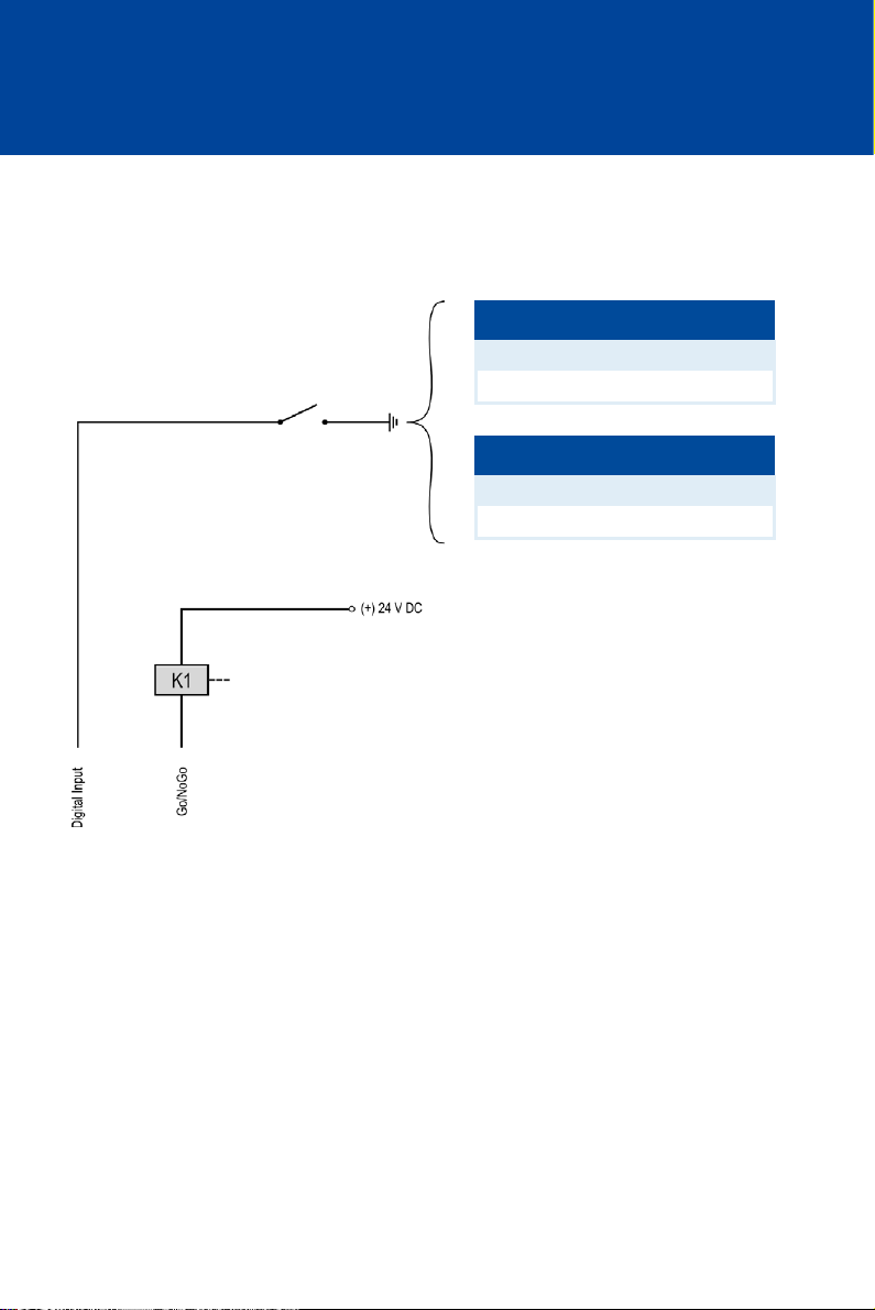
6 WIRING OF THE DEVICE
6.1.16 Wiring – Digital Input, Go/NoGo
The function of the digital input (Switch Start/Stop or Switch A/B) is specified via the
parameterization of the ignition controller (see Select Function for Digital Input on page 87).
Digital input
Function Switch Start/Stop
open Ignition - ON
closed Ignition - OFF
or
Function Switch A/B
open Schedule A
closed Schedule B
K1 = Go/NoGo relay
56 Rev. 01/2015
Page 57

7
FUNCTIONS
The ignition controllers of the MIC500 series include freely configurable safety and auxiliary
functions that, amongst others, can shut down the engine in case of fault.
Angle indications in the operating manual
All angles in this operating manual are given in °crankshaft. Exceptions are
clearly identified.
7.1 Monitoring of Pickup Signal
The MIC500 monitors the pickup signal. Possible errors are indicated on the device by the LED.
For further information on errors, please refer to the overview in section Message and Error
Overview on page 113.
7.2 Go/NoGo
The Go/NoGo output is an open collector output that is closed during firing and opens when the
ignition switches off. The maximum switching current is 100 mA. The output can drive an
external relay that, for example, opens a gas valve.
The following errors can cause the ignition outputs to shut down:
– Overspeed
– Pickup error
– Insufficient supply voltage (Low Power)
– Misfire rate
Rev. 01/2015 57
Page 58

7 FUNCTIONS
7.3 Remote-Controlled Ignition Release
No digital input at P/N 06.00.513
The device type P/N 06.00.513 is designed as a replacement for the ignition
controller Caterpillar® 163-6164. Thus, the device does not have the digital
input (Switch A/B, Switch Start/Stop) as described in this operating manual.
With this device type, schedule A settings are applied solely for ignition
timing configuration.
Via the digital input, the ignition of the MIC500 ignition controller can be switched on and off by
a master control.
In order to use this function, the digital input must be set to the function Switch Start/Stop. In
this mode, the ignition controller applies solely the settings from schedule A. If the digital input
is closed, the ignition of the ignition controller is switched off.
A security speed can be specified, above which the ignition after a switch-off cannot be activated
until the engine is at a standstill.
For the configuration of the digital input, see section Select Function for Digital Input on page 87.
For the configuration of the security speed, see section Set Security Speed on page 85.
58 Rev. 01/2015
Page 59

7.4 Schedules A/B
Operational safety!
If you use schedules A and B, the advanced timing point should be linked to
schedule B (switch closure). If a wire ruptures, schedule A is automatically
selected with the retarded (and thus safer) timing point.
No digital input at P/N 06.00.513
The device type P/N 06.00.513 is designed as a replacement for the ignition
controller Caterpillar® 163-6164. Thus, the device does not have the digital
input (Switch A/B, Switch Start/Stop) as described in this operating manual.
With this device type, schedule A settings are applied solely for ignition
timing configuration.
The MIC500 ignition controllers offer two separate schedules with the following setting options:
– Timing limits
– Activating/deactivating the ignition timing adjustment via the analog input
– Activating/deactivating the speed curve
– Timing offset for schedule B
In order to use both schedules, the digital input must be set to the Switch A/B function (see
Select Function for Digital Input on page 87). If the digital input is closed, the ignition controller
uses the settings from schedule B. A possible application for this is e. g. operation with different
gases.
To configure the schedules, read the following sections:
– Set Ignition Timing Limits on page 93
– Activate Functions for Schedules A and B on page 89
– Set Timing Offset for Schedule B on page 95
Rev. 01/2015 59
Page 60
7 FUNCTIONS
7.5 Timing Correction
Operational safety!
The MIC500 ignition controller must first be correctly configured for the
engine being used before you can start the engine.
An incorrect configuration can result in damage to the engine.
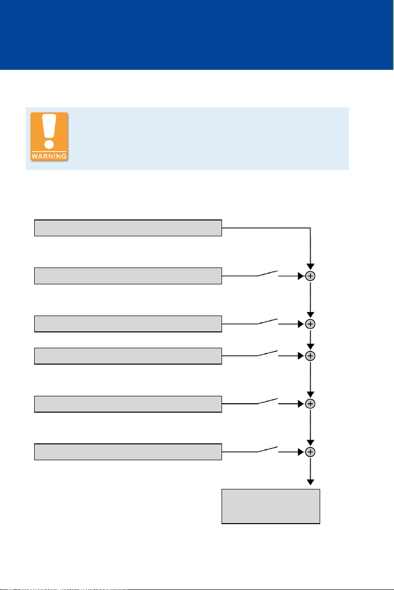
The ignition controller has several functions for ignition timing adjustment, which can be
activated or deactivated. The following chart shows an overview.
0° BTDC
Global:
Potentiometer
Per schedule:
4-20 mA input
Speed curve
Schedule B:
Ignition timing offset
Per cylinder:
Cylinder-to-cylinder alignment
With MIC500 ignition controllers, the maximum adjustment range for ignition timing is 38°.
60 Rev. 01/2015
Limited by the min./max.
ignition timing per
schedule
Page 61

The various functions of the ignition timing adjustment are explained in detail in the following
sections.
Influences on ignition timing
Be aware that the actual ignition timing of the engine can also be influenced
by external signals (e. g. 4-20 mA input).
7.5.1 Manual Timing Correction
Explosion hazard!
Never remove the cover for timing adjustment, unless the system is not
located in an explosive environment.
Reinsert the cover after every ignition timing adjustment made using the
potentiometer.
The ignition controllers of the MIC500 series include a permanently installed overwind-protected
potentiometer (Timing Adjustment) for manually adjusting the timing point. The maximum
adjustment range is defined by the user through the corresponding limits.
The potentiometer can be deactivated, e.g. to prevent unauthorized changes in the timing.
The potentiometer is protected by a cover. Remove the cover only if the ignition controller is
located in a non-explosive area. Reinsert the cover after every ignition timing adjustment made
using the potentiometer.
To configure the potentiometer, see sections Activate Potentiometer on page 88 and Set
Potentiometer Limits on page 91.
Rev. 01/2015 61
Page 62

7 FUNCTIONS
7.5.2 Analog Current Input – 4-20 mA
The timing point control can be adjusted with a linear 4-20 mA signal. This signal can be
supplied, for example, by a potentiometer, a pressure sensor for charging pressure, or a
detonation controller.
With the analog process signal (4-20 mA current loop signal) at the 4-20 mA input, the timing
point can be offset in the advanced or retarded direction within a defined range.
At the 4-20 mA PWR voltage output, the input voltage is supplied as an auxiliary voltage that can
be used for supplying power to external sensors (not available for P/N 06.00.550).
To configure the analog input, see sections Activate Functions for Schedules A and B on page 89
and Set Limits for 4-20 mA Input on page 95.
7.5.3 Speed Curve
To optimize the ignition, for example, during the start phase of the engine, a speed curve can be
defined for the MIC500 ignition controllers. To create this curve, up to five adjustable speed
points are available.
To configure the speed curve, see sections Activate Functions for Schedules A and B on page 89
and Set Speed Curve on page 97.
7.5.4 Cylinder-to-Cylinder Alignment
Use of measuring unit
Use this setup option only if a suitable measuring unit is available for
determining the optimum timing point, so that the result of a change can be
assessed immediately.
To optimize combustion, the cylinder-to-cylinder alignment enables the user to change the
ignition timing for individual cylinders. The ignition timing for each cylinder can be adjusted by
max. 2° in both directions compared to the scheduled ignition timing.
To activate the cylinder-to-cylinder alignment, see section Activate Cylinder-to-Cylinder
Alignment on page 87. To fine tune the individual cylinders, see section Cylinder-to-Cylinder
Alignment on page 103.
7.6 Misfire Detection
The MIC500 ignition controllers include a misfire detection for the primary side (open circuit),
which measures all misfires per cycle and compares the result to a misfire rate set by the user. If
this rate is exceeded, the ignition will be automatically deactivated. For the configuration of the
misfire rate, see chapter Set Misfire Rate on page 86.
62 Rev. 01/2015
Page 63

7.7 Ignition Energy
Depending on the gas quality and the application, it is possible to vary the available ignition
energy. In a range between 15 % to 100 %, any value can be selected. Fast-igniting gases such as
propane require relatively small levels of energy, whereby poorly igniting gases such as landfill
gas require lots of energy to ignite.
To adapt the ignition energy, see section Set Ignition Energy on page 102.
Rev. 01/2015 63
Page 64

8 ADJUSTMENTS
Operational safety!
The MIC500 ignition controller must first be correctly configured for the
engine being used before you can start the engine.
An incorrect configuration can result in damage to the engine.
Before using the MIC500 series ignition controller, all parameters relevant to the engine and the
application must be configured. This parameterization can be carried out via a computer
(PC/laptop) using Ignition Control software. You can also use a hand-held programmer available
from MOTORTECH (P/N 06.05.008) as an option.
In addition, you receive information about the current status of your engine via the Ignition
Control software or the hand-held programmer.
For help with installation and general operating instructions on Ignition Control, read chapter
Ignition Control on page 64. For general operating instructions on the hand-held programmer,
read chapter Hand-Held Programmer on page 69.
8.1 Ignition Control
8.1.1 System Requirements Ignition Control
The following minimum requirements must be met for the Ignition Control software:
– RS232 interface; alternatively USB 1.1 with a USB to RS232 converter
– Screen with at least QSVGA resolution (400 x 300 pixels)
– Operating system: Windows 2000 / NT / XP / 7
8.1.2 Installing Ignition Control
Explosion hazard!
Use the RS232 interface solely in a non-explosive atmosphere.
Reinsert the RS232 interface cover after each usage and tighten it with a
tightening torque of 1 Nm (0.7 lb-ft).
If you want to program the ignition controller from a PC or laptop, the Ignition Control software
from the supplied storage device (USB flash drive or CD-ROM) must first be installed on the
computer.
Rev. 01/2015 64
Page 65
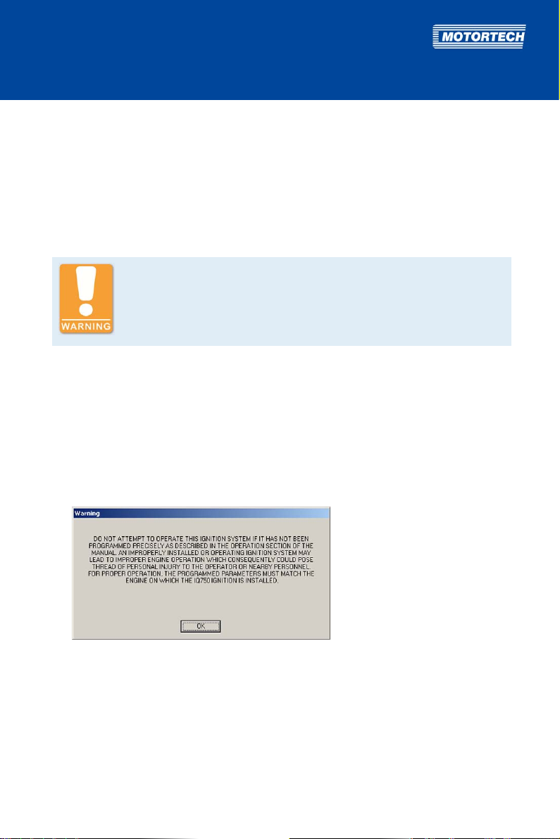
Proceed as follows:
1. Select a location for saving Ignition Control on the hard disk of your computer, e.g. by
creating a file folder with the name Ignition Control.
2. From the subdirectory MIC software\WIN2000-NT-XP on the supplied storage device, copy
the file IC.exe to the location you selected on the hard disk of your computer.
3. Note the location where the Ignition Control software is saved on your computer. Put a link
on the desktop if needed by right-clicking mouse on IC.exe -> Send to -> Desktop.
Explosion hazard!
Never remove the RS232 interface cover, unless the system is not located in
an explosive environment.
4. Connect the ignition controller to your computer using the provided RS232 interface cable.
If your computer does not have an RS232 interface, you can also use a USB to RS232
converter. Connect the USB to RS232 converter to your computer and connect the RS232
interface cable to the RS232 connector of the converter and the ignition controller.
5. Ensure that the ignition controller is connected to the power supply and that the status LED
on the ignition controller is flashing every 2 seconds for the device to be ready for operation.
6. Launch the Ignition Control software on your computer by double-clicking the IC.exe file.
The following warning is displayed:
Rev. 01/2015 65
Page 66
8 ADJUSTMENTS
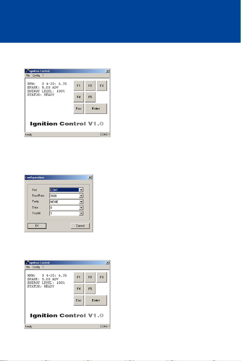
7. Read through the information carefully and confirm with OK.
The main view is displayed.
8. If you are not using COM1 for the connection between the ignition controller and your
computer, and there are no status values displayed on the left of the main view (RPM, 4-20,
SPARK etc.), adapt Ignition Control to the relevant communication interface via the menu
item Config -> RS232:
The Configuration window is displayed.
9. Select the desired interface under Port. All other parameters remain unchanged.
10. Confirm your selection with OK.
The window closes and the main view is displayed.
66 Rev. 01/2015
Page 67
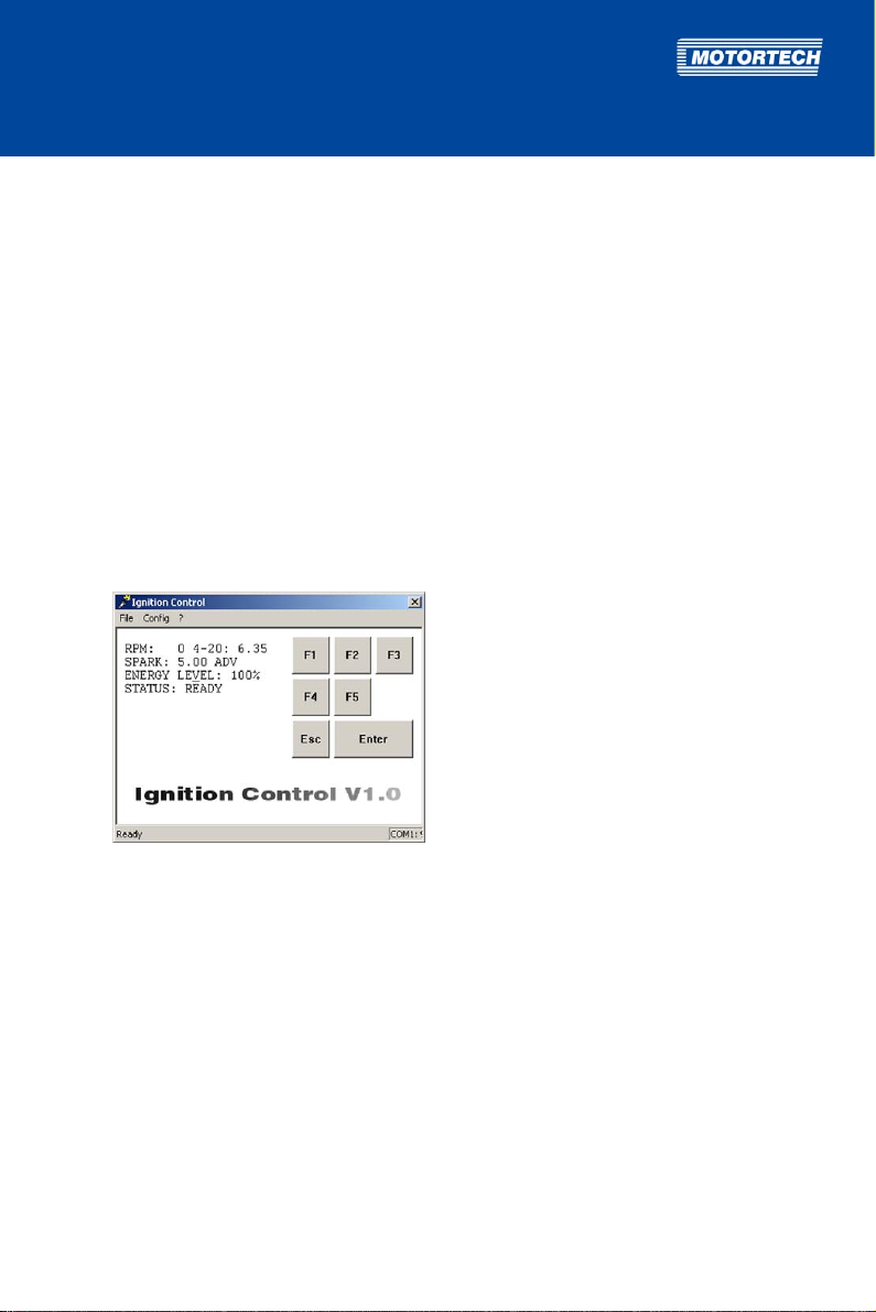
After correctly selecting the port, you will see status values on the left side of the main
view. Ignition Control is installed and ready for operation.
If there are still no status values displayed on the left side of the main view, check the
cable connection between the ignition controller and the computer (see step 4), ensure
that the ignition controller is ready for operation (see step 5) as well as the selected
communication interface (see step 8).
8.1.3 Starting Ignition Control
To start Ignition Control after installing it on your computer, proceed as follows:
1. Ensure that the ignition controller is connected to the power supply and that the status LED
on the ignition controller is flashing every 2 seconds for the device to be ready for operation.
2. Ensure that your computer is connected with the ignition controller via the RS232 interface
cable.
3. Launch the Ignition Control software on your computer by double-clicking the IC.exe file.
You see the main view.
Rev. 01/2015 67
Page 68
8 ADJUSTMENTS
8.1.4 Menu Bar and Buttons
Menu Bar
The following functions are available to you via the entries in the menu bar:
Menu Function
File -> Exit
Config -> RS232
? -> About Ignition Control
? -> Warning
Buttons
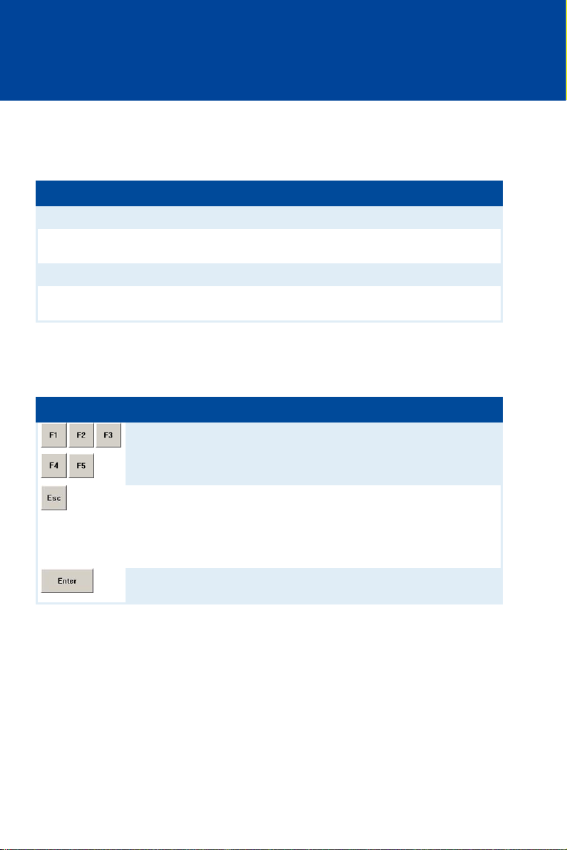
The following table gives an overview on the buttons and their functions. Instead of the buttons,
you can also use the corresponding keys on the computer keyboard.
Button Key Function
[F1] to [F5] Function keys
[Esc] Leave/open parameterization level
[Enter] Confirm
Finishes Ignition Control.
Opens the Configuration window for the configuration of
the RS232 interface.
Opens information on the program.
Opens the warning that is displayed when the program is
launched.
Depending on the opened view, the function keys are
assigned differently. The respective assignment is
shown in the view.
With this button, you close the currently opened view
and return back to main view.
In the main view, you open the parameterization level
with this button.
With this button, you confirm a selection or entry.
68 Rev. 01/2015
Page 69
8.2 Hand-Held Programmer
8.2.1 RS232 Interface Adjustments
If you wish to program the MIC500 ignition controller from the optionally available hand-held
programmer, the RS232 interface of the hand-held programmer must be configured to
correspond to the RS232 interface of the MIC500.
Proceed as follows:
1. Switch the hand-held programmer on with the [ON/OFF] key.
2. Simultaneously press [SHIFT] and [CTRL] and then also [F1].
The first parameter is displayed.
3. Set the following parameters in succession:
– Baud: 9600
– Data Bits: 7
– Parity: ignore
– Display Pe: enabled
– Repeat: fast
– Echo: disabled
– Handshake: disabled
– Self Test: disabled
– Power Saver: enabled
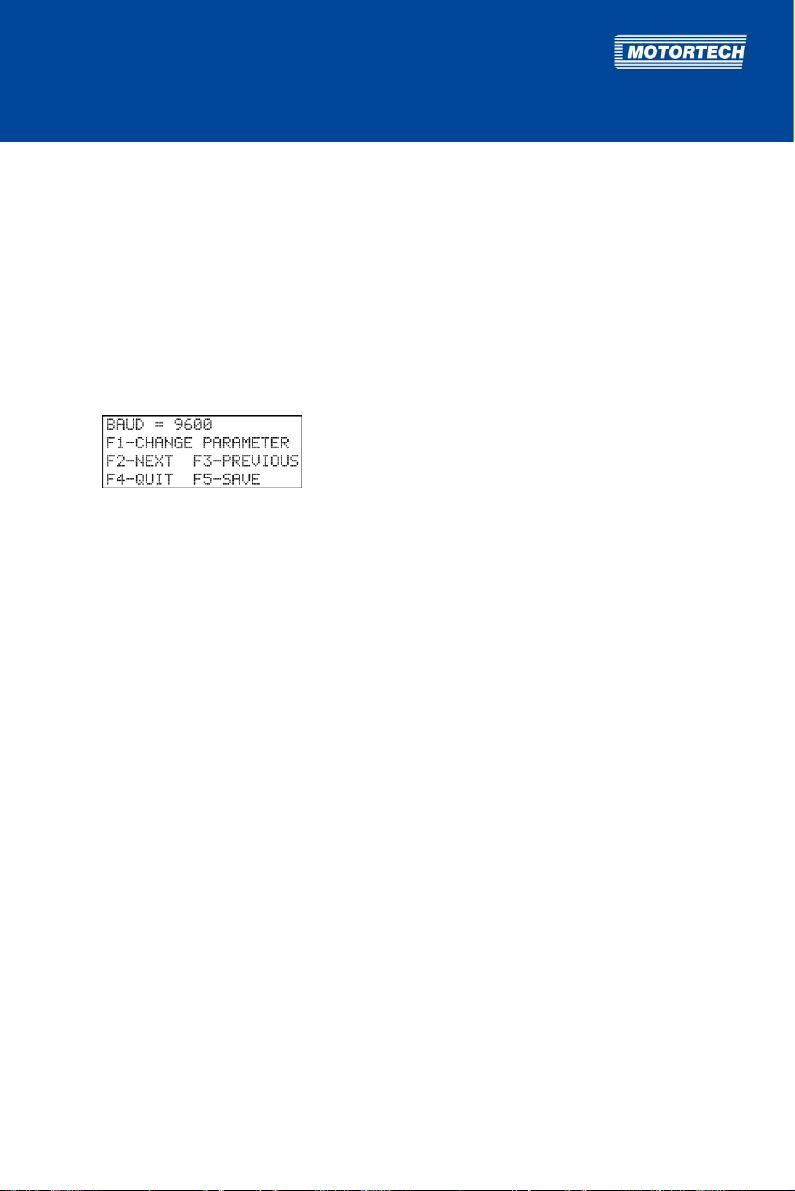
The respective value can be changed incrementally by pressing [F1]. You can go on to the
next parameter by pressing [F2].
4. Save the settings by pressing [F5].
The hand-held programmer is now configured for connection with the MIC500 and ready
for use.
Rev. 01/2015 69
Page 70
8 ADJUSTMENTS
8.2.2 Switching on the Hand-Held Programmer
Explosion hazard!
Never remove the RS232 interface cover, unless the system is not located in
an explosive environment.
Explosion hazard!
Use the RS232 interface solely in a non-explosive atmosphere.
Reinsert the RS232 interface cover after each usage and tighten it with a
tightening torque of 1 Nm (0.7 lb-ft).
To switch the hand-held programmer on, proceed as follows:
1. Connect the hand-held programmer to the MIC500 ignition controller via the RS232
connector.
2. Ensure that the ignition controller is connected to the power supply and that the status LED
on the ignition controller is flashing every 2 seconds for the device to be ready for operation.
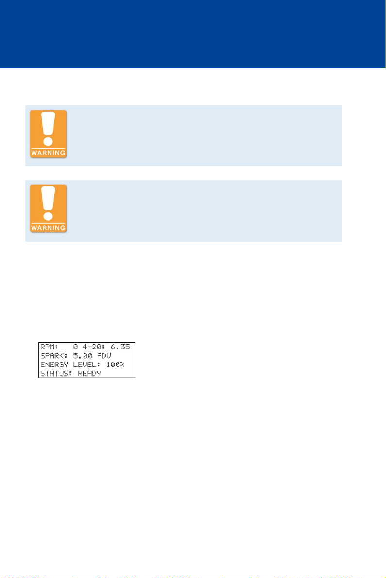
3. Switch the hand-held programmer on by briefly pressing the [ON/OFF] key.
You see the main view.
70 Rev. 01/2015
Page 71

y
y
y
y
8.2.3 Keys of the Control Panel
The following table gives an overview of the keys on the control panel and their functions.
Key Function
[ON/OFF] On/Off ke
Key for switching the hand-held programmer on and off
[F1] to [F5] Function keys
Depending on the opened view, the function keys are assigned
differently. The respective assignment is shown in the corresponding
view.
[+/A] to ["/Y],
[ESC/Z]
[0] to [9] Number keys
[CTRL] Control ke
[ESC] Leave/open parameterization level
[BACKSP] Backspace ke
[SPACE] Space bar
[ENTER] Confirm
[SHIFT] Shift ke
Combination letter and character keys
Keys for entering letters and characters.
Without simultaneously pressing the shift key, the corresponding letter
is entered, e.g. "A" with the [+/A] key. If the shift key is pressed
simultaneously, the corresponding character above the letter is
entered, e.g. "+" with the [+/A] key. If the shift key is pressed with the
[ESC/Z] key, the ESC function is initiated (see functional description
below).
Numbers can be entered with these keys.
Initiates the control functions of the hand-held programmer when
combined with other keys.
With this button, you close the currently opened view and return back to
main view.
In the main view, you open the parameterization level with this key.
Deletes the last character entered.
Key for entering empty characters
With this key, you confirm a selection or entry.
Keys with dual functions will enter the upper character or initiate the
upper function if the shift key is held simultaneously.
Rev. 01/2015 71
Page 72

8 ADJUSTMENTS
8.3 Conventions Used in the Following
In the subsequent sections, the views that allow you to enter settings or provide you with
information will be explained. Therefore, the following conventions apply:
Key Combinations
– The keys to be pressed on the computer keyboard or the hand-held programmer are shown
in square brackets, e. g. [E] indicates the E key.
– A plus symbol (+) between two keys indicates that they are to be pressed simultaneously.
– The key combinations for the computer keyboard also apply to the hand-held programmer,
unless otherwise stated.
– In the Ignition Control software, the corresponding buttons (see Menu Bar and Buttons on
page 68) can also be used.
Short Hand Notation
Setting changes to be carried out are indicated in abbreviated form, using an arrow (->) to
separate the individual steps.
Example
[Shift]+[E] -> [F1] -> Enter energy level -> [Enter] -> [F5]
Meaning
1. Press the shift key and the E key simultaneously.
2. Press the F1 key or click on the F1 button in Ignition Control.
3. Enter the energy level.
4. Press the Enter key on your computer keyboard or click on the Enter button in Ignition
Control.
5. Press the F5 key or click on the F5 button in Ignition Control.
72 Rev. 01/2015
Page 73
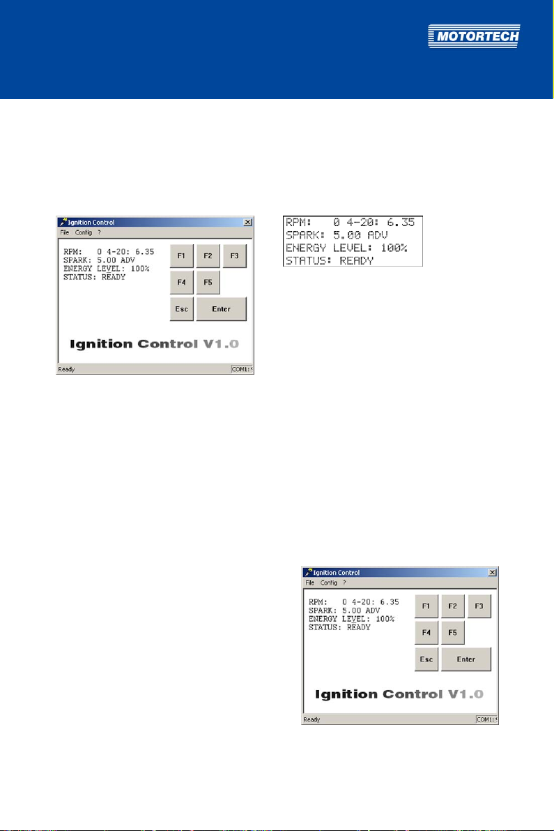
Screen Views
In the following, the screen views are limited to the views in the Ignition Control software. The
hand-held programmer views correspond to the Ignition Control views.
Example
Ignition Control view: Hand-held programmer view:
8.4 Main View
The main view is shown:
– automatically when the Ignition Control software is started or when the hand-held
programmer is switched on
– when leaving other views including the parameterization level by pressing [Esc]
In the main view, you receive the following information on the current status of the MIC500
ignition controller:
– RPM:
current engine speed
– 4-20:
current value of the analog current signal in
mA
– SPARK:
currently set timing
– ENERGY LEVEL:
currently set energy level
– STATUS:
current status of the ignition controller
Rev. 01/2015 73
Page 74

8 ADJUSTMENTS
Following statuses are possible:
– READY
The ignition controller is ready for operation.
– FIRING
The ignition controller is firing.
– NO MPU
No input signal detected.
– TOO SLOW
The speed is too slow (less than 60 crankshaft revolutions or 30 camshaft
revolutions). This can be caused by an incorrect sequence number, a wrong trigger
disc or a weak pickup signal.
– WAIT FOR 0
The ignition controller is waiting for engine standstill.
– SECURITY ON
The Start/Stop input is closed.
– OVERSPEED ERR
The defined overspeed level was exceeded.
– CAM MPU ERROR
Errors with the pickup signal were detected.
– OUTPUT FAILURERATE EXCEEDS
The defined misfire rate for the indicated output was exceeded.
– LOW VOLTAGE
The supply voltage has fallen below 10 V.
– CHECKSUM ERR
A loss in voltage occurred in programming mode, which led to a failure. The unit
must be re-parameterized.
74 Rev. 01/2015
Page 75
8.5 Parameterization Level
8.5.1 General Operation of the Parameterization Level
Opening Parameterization Level
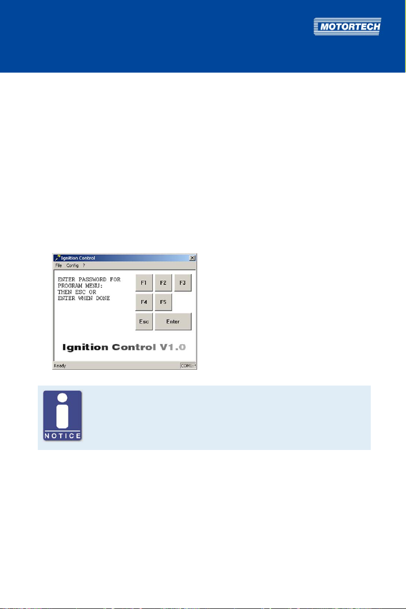
The parameterization of the ignition controller is done on the parameterization level. To open
this level, proceed as follows:
1. First ensure that the engine connected to the ignition controller is not running.
2. Ensure that the ignition controller is connected to the power supply and that the status LED
on the ignition controller is flashing every 2 seconds for the device to be ready for operation.
3. Ensure that the ignition controller is connected to the computer or the hand-held
programmer via the RS232 interface cable.
4. In order to open the parameterization level, press the [Esc] key from the main view.
You are requested to enter your password.
Password for the parameterization level
The password required for access to the parameterization level is obtained
from your MOTORTECH contact person (see Customer Service Information on
page 117).
Rev. 01/2015 75
Page 76
8 ADJUSTMENTS
5. Enter your password and confirm it by pressing the [Enter] button.
After correctly entering the password, the window changes to parameter view. The
MIC500 ignition controller is now in programming mode (status LED on device flashes 6
times). The parameter SEQ. NUMBER is displayed.
Navigating Through the Parameters
With the following keys, you can change from one parameter to the next in parameter view:
[F2]: One step further to the next parameter
[F3]: One step back to the previous parameter
Changing a Parameter
To change a parameter, proceed as follows:
1. Select the desired parameter in parameter view with [F2] or [F3].
2. To change the displayed parameter, press [F1].
The window for changing the relevant parameter appears.
3. Depending on the parameter, enter either the desired value or select a pre-defined value
with [F1] or [F2].
4. Always confirm the values entered by pressing [Enter]. This step is omitted when pre-defined
values are selected using [F1] or [F2].
If you do not wish to change the parameter displayed, exit the parameter configuration
view by pressing [Esc]. This returns you to parameter view.
If you enter values beyond the permissible range for the respective parameter, these
values are ignored and the existing value remains unchanged.
76 Rev. 01/2015
Page 77

Save each parameter separately
The values that you change for control are not taken over by the ignition
controller until you have saved the changes. Therefore, save each individual
parameter change with [F5].
5. Save the parameter change with [F5]. The data is not applied by the ignition controller for
control until it has been saved.
6. To change additional parameters, return to step 1.
Leaving Parameterization Level
To leave the parameterization level and return to the main view, proceed as follows:
1. From the configuration view of a parameter, press the [Esc] key to return to parameter view.
If you have changed the respective parameter, the change will only be saved if you press
[F5] prior to exiting.
2. From the parameter view, press [Esc] to return to the main view.
The MIC500 ignition controller exits the programming mode and is ready for operation
(LED flashes briefly every 2 seconds).
Using the Help Function
Via the help function, further information is available for every shown parameter.
– You can access help information for the displayed parameter by pressing [F4].
– You can jump between the help texts by pressing [F2] to jump a step ahead, and [F3] to jump
a step back.
– You can exit the Help menu by pressing [Esc].
This returns you to parameter view.
Rev. 01/2015 77
Page 78

8 ADJUSTMENTS
8.5.2 Brief Overview of Parameters
In the following table, you will find a brief overview of the ignition controller's configurable
parameters. For more detailed information about the individual parameters, see the
corresponding sections.
Display of parameters
The parameters indicated with a star (*) are dependent on the settings of
other parameters and are not shown in specific instances. Detailed
information on the display of these parameters can be found in the
corresponding sections.
No. Parameter Function Configuration
1 SEQ. NUMBER The sequence number reflects the
engine's configuration and must be set
according to the connected engine.
2 RESET BTDC Angular position of the reset signal from
the upper dead center of the first
cylinder
3 OVERSPEED Overspeed value, above which the
ignition is switched off if exceeded.
4 SECURITY SPEED Security speed, below which the ignition
can be switched on or off via the digital
input if set to Switch Start/Stop function.
5 MISFIRE RATE Maximum permissible misfire rate,
above which the engine will be switched
off.
6 CYL TO CYL Activate or deactivate cylinder-to-
cylinder alignment
7 CONTACT I/P Use of digital input for switching the
ignition on or off (function Switch
Start/Stop) or for operating with two
different schedules (function Switch
A/B)
8 POT TIMING Activate or deactivate the potentiometer see Activate
see Set Sequence
Number on page
80
see Set Reset
Position on page
84
see Set Overspeed
on page 84
see Set Security
Speed on page 85
see Set Misfire
Rate on page 86
see Activate
Cylinder-toCylinder Alignment
on page 87
see Select Function
for Digital Input on
page 87
Potentiometer on
page 88
78 Rev. 01/2015
Page 79

No. Parameter Function Configuration
9 SPEED CURVE A Activate or deactivate the speed curve
10 4-20 A 4-20 mA input for activating or
11 SPEED CURVE B Activate or deactivate the speed curve
12 4-20 B 4-20 mA input for activating or
13 POT CCW Maximum potentiometer angle BTDC
14 POT CW Minimum potentiometer angle BTDC
15 MAX ADV A Earliest permissible ignition timing for
16 MAX RET A Latest permissible ignition timing for
17 MAX ADV B* Earliest permissible ignition timing for
18 MAX RET B* Latest permissible ignition timing for
19 B OFFSET* Timing offset for schedule B see Set Timing
20 4mA TIMING* Ignition timing adjustment via the
21 20mA TIMING* Ignition timing adjustment via the
22 DFLT 4-20* Ignition timing adjustment in the event
23 # SPEED POINTS* Number of speed points for the speed
24 BP1* to BP5* Definition of the speed value and the
for schedule A
deactivating schedule A
for schedule B
deactivating schedule B
with left rotating direction
with right rotating direction
schedule A
schedule A
schedule B
schedule B
analog signal at 4 mA
analog signal at 20 mA
of signal loss at the 4-20 mA input
curve (max. 5 points)
ignition timing adjustment for the
individual speed curve speed points BP1
to BP5
see Activate
Functions for
Schedules A and B
on page 89
see Set Potentio-
meter Limits on
page 91
see Set Ignition
Timing Limits on
page 93
Offset for Schedule
B on page 95
see Set Limits for
4-20 mA Input on
page 95
see Set Speed
Curve on page 97
Rev. 01/2015 79
Page 80
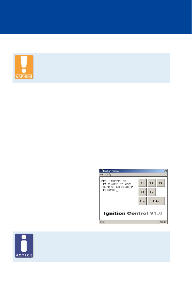
8 ADJUSTMENTS
8.5.3 Set Sequence Number
Operational safety!
Please ensure that the set sequence number of the MIC500 ignition
controller corresponds to your engine.
An incorrect configuration can result in damage to the engine.
The sequence number (SEQ. NUMBER) reflects the engine's configuration. The following
application properties can be set with the sequence number:
– Number of outputs
– Ignition offset
– Pattern and mounting location of trigger disc
– Output firing order
– Number of combustion strokes of the engine
The sequence number that corresponds to your application can be found on the following
configuration table.
If the sequence number is changed, all ignition timing adjustments of the cylinder-to-cylinder
alignment (see Cylinder-to-Cylinder Alignment on page 103) are reset to 0°.
Proceed as follows:
Open parameterization level ->
[F2] to SEQ. NUMBER -> [F1] ->
Enter sequence number (see below) ->
[Enter] -> [F5]
Deactivate misfire monitoring
For sequences 22, 23, 29, 34 and 36, indicated by a star (*), it is necessary
to set the MISFIRE RATE to via Ignition Control, which deactivates misfire
monitoring.
80 Rev. 01/2015
Page 81

Seq. Number of
outputs
Ignition
offset
Trigger Trigger disc
mounting
Ignition output Strokes
location
1 2 360-360 2 + 1 Camshaft A-B 4-stroke
2 3 240-240 3 + 1 Camshaft A-B-C 4-stroke
3 3 120-120 3 + 1 Crankshaft A-B-C 2-stroke
4 6 50-70 3 + 1 Crankshaft A-B-C-D-E-F 2-stroke
5 6 30-90 3 + 1 Crankshaft A-B-C-D-E-F 2-stroke
6 6 90-30 3 + 1 Crankshaft A-B-C-D-E-F 2-stroke
7 2 90-90 4 + 1 Crankshaft A-B 2-stroke
8 4 180-180 4 + 1 Camshaft A-B-C-D 4-stroke
9 4 90-90 4 + 1 Crankshaft A-B-C-D 2-stroke
10 8 20-70 4 + 1 Crankshaft A-B-C-D-E-F-K-L 2-stroke
11 8 60-30 4 + 1 Crankshaft A-B-C-D-E-F-K-L 2-stroke
12 8 45-45 4 + 1 Crankshaft A-B-C-D-E-F-K-L 2-stroke
13 8 30-60 4 + 1 Crankshaft A-B-C-D-E-F-K-L 2-stroke
14 5 72-72 5 + 1 Crankshaft A-B-C-D-E 2-stroke
15 5 144-144 5 + 1 Camshaft A-B-C-D-E 4-stroke
16 10 54-90 5 + 1 Camshaft A-B-C-D-E-F-K-L-M-N 4-stroke
17 12 30-90 6 + 1 Camshaft A-B-C-D-E-F-K-L-M-
4-stroke
N-P-R
18 12 40-80 6 + 1 Camshaft A-B-C-D-E-F-K-L-M-
4-stroke
N-P-R
19 12 48-72 6 + 1 Camshaft A-B-C-D-E-F-K-L-M-
4-stroke
N-P-R
20 12 56-64 6 + 1 Camshaft A-B-C-D-E-F-K-L-M-
4-stroke
N-P-R
21 6 120-120 6 + 1 Camshaft A-B-C-D-E-F 4-stroke
22* 3 60-180 6 + 1 Crankshaft A-B-E 2-stroke
23* 4 120-60 6 + 1 Crankshaft A-C-D-F 2-stroke
24 6 60-60 6 + 1 Crankshaft A-B-C-D-E-F 2-stroke
25 7 102,8-102,8 7 + 1 Camshaft A-B-C-D-E-F-K 4-stroke
26 7 51,43-51,43 7 + 1 Crankshaft A-B-C-D-E-F-K 2-stroke
27 8 90-90 8 + 1 Camshaft A-B-C-D-E-F-K-L 4-stroke
Rev. 01/2015 81
Page 82

8 ADJUSTMENTS
Seq. Number of
outputs
28 8 45-45 8 + 1 Crankshaft A-B-C-D-E-F-K-L 2-stroke
29* 8 45-45 8 + 1 Crankshaft A-C-E-K-M-P-S-U 2-stroke
30 16 10-35 8 + 1 Crankshaft A-B-C-D-E-F-K-L-M-
31 16 21-24 8 + 1 Crankshaft A-B-C-D-E-F-K-L-M-
32 16 22,5-22,5 8 + 1 Crankshaft A-B-C-D-E-F-K-L-M-
33 16 30-60 8 + 1 Camshaft A-B-C-D-E-F-K-L-M-
34* 4 90-90 8 + 1 Crankshaft A-E-M-S 2-stroke
35 10 36-36 10 + 1 Crankshaft A-B-C-D-E-F-K-L-M-N 2-stroke
36* 5 72-72 10 + 1 Crankshaft A-C-E-K-M 2-stroke
37 12 50-70 12 + 1 Camshaft A-B-C-D-E-F-K-L-M-
38 12 55-65 12 + 1 Camshaft A-B-C-D-E-F-K-L-M-
39 12 60-60 12 + 1 Camshaft A-B-C-D-E-F-K-L-M-
40 12 75-45 12 + 1 Camshaft A-B-C-D-E-F-K-L-M-
41 16 20-70 8 + 1 Camshaft A-B-C-D-E-F-K-L-M-
42 12 90-30 6 + 1 Camshaft A-B-C-D-E-F-K-L-M-
43 12 42-78 6 + 1 Camshaft A-B-C-D-E-F-K-L-M-
44 16 60-30 8 + 1 Camshaft A-B-C-D-E-F-K-L-M-
45 16 45-45 8 + 1 Camshaft A-B-C-D-E-F-K-L-M-
46 12 60-60 6 + 1 Camshaft A-B-C-D-E-F-K-L-M-
Ignition
offset
Trigger Trigger disc
mounting
location
Ignition output Strokes
2-stroke
N-P-R-S-T-U-V
2-stroke
N-P-R-S-T-U-V
2-stroke
N-P-R-S-T-U-V
4-stroke
N-P-R-S-T-U-V
4-stroke
N-P-R
4-stroke
N-P-R
4-stroke
N-P-R
4-stroke
N-P-R
4-stroke
N-P-R-S-T-U-V
4-stroke
N-P-R
4-stroke
N-P-R
4-stroke
N-P-R-S-T-U-V
4-stroke
N-P-R-S-T-U-V
4-stroke
N-P-R
82 Rev. 01/2015
Page 83

Seq. Number of
outputs
Ignition
offset
Trigger Trigger disc
mounting
Ignition output Strokes
location
47 16 50-40 8 + 1 Camshaft A-B-C-D-E-F-K-L-M-
N-P-R-S-T-U-V
48 16 40-50 8 + 1 Camshaft A-B-C-D-E-F-K-L-M-
N-P-R-S-T-U-V
49 12 50-70 6 + 1 Camshaft A-B-C-D-E-F-K-L-M-
N-P-R
50 12 55-65 6 + 1 Camshaft A-B-C-D-E-F-K-L-M-
N-P-R
51 12 75-45 6 + 1 Camshaft A-B-C-D-E-F-K-L-M-
N-P-R
52 12 45-75 6 + 1 Camshaft A-B-C-D-E-F-K-L-M-
N-P-R
4-stroke
4-stroke
4-stroke
4-stroke
4-stroke
4-stroke
Rev. 01/2015 83
Page 84
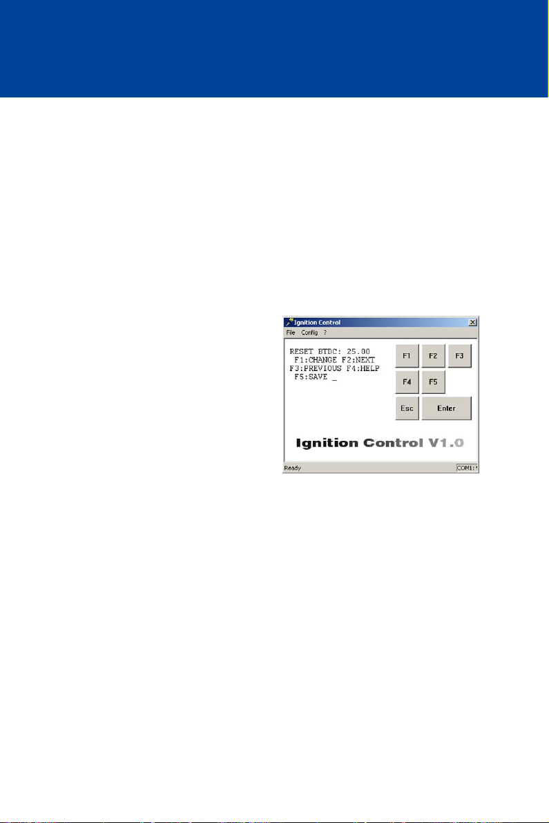
8 ADJUSTMENTS
8.5.4 Set Reset Position
With the RESET BTDC parameter, you define the angular position of the reset signal from the
upper dead center of the first cylinder. All other cylinders are assessed based on this value. If
there is a difference between the actual and the displayed timing, adjust this value accordingly.
Value range:
– 25.00 to 60.00 with up to two decimal places
Enter decimal places with a period as the delimiter, e.g. 35.55.
– The value for RESET BTDC must be at least 2° in advance of the earliest timing of
schedule A (MAX ADV A) and, if activated, of schedule B (MAX ADV B, also see Set
Ignition Timing Limits on page 93).
Proceed as follows:
Open parameterization level ->
[F2] to RESET BTDC -> [F1] ->
Enter reset position ->
[Enter] -> [F5]
8.5.5 Set Overspeed
With the OVERSPEED parameter, you can specify the maximum overspeed value. If this value is
exceeded, the ignition is switched off and the device will indicate an error by flashing the status
LED (four times).
Value range:
– 0 to 5000, whole numbers
84 Rev. 01/2015
Page 85
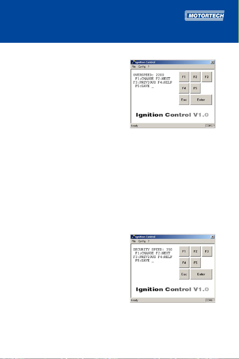
Proceed as follows:
Open parameterization level ->
[F2] to OVERSPEED -> [F1] ->
Enter overspeed ->
[Enter] -> [F5]
8.5.6 Set Security Speed
With the SECURITY SPEED parameter, you can specify the speed value for the security speed.
Below this speed, the ignition can be switched on or off via the digital input if set to function
Switch Start/Stop (see Select Function for Digital Input on page 87). The instant this speed is
exceeded, the ignition cannot be restarted until the engine is at a standstill if shut down via the
digital input.
The security speed must be greater than the maximum starter speed. It is not possible to enter
values higher than the currently set overspeed (Parameter OVERSPEED, see Set Overspeed on
page 84).
Value range:
– 0 to OVERSPEED, whole numbers
Proceed as follows:
Open parameterization level ->
[F2] to SECURITY SPEED -> [F1] ->
Enter security speed ->
[Enter] -> [F5]
Rev. 01/2015 85
Page 86
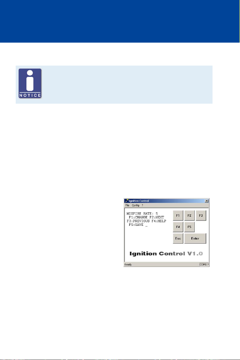
8 ADJUSTMENTS
8.5.7 Set Misfire Rate
Deactivate misfire monitoring
For sequences 22, 23, 29, 34 and 36, it is necessary to set the MISFIRE RATE
to via Ignition Control, which deactivates misfire monitoring.
With the MISFIRE RATE parameter, you can specify the permissible misfires per second (primary
side, open circuit) across all outputs. If the specified value is exceeded, the engine will be
switched off. The exceeded misfire rate is indicated by the status LED of the device flashing six
times (see Message and Error Overview on page 113).
Misfire monitoring can be deactivated by setting the value to 0 or 255. Depending on the engine
type, setting a misfire rate of 3 to 15 is recommended.
For sequences 22, 23, 29, 34 and 36, the misfire rate must be set to , which deactivates misfire
monitoring.
Value range:
– 0 to 255, whole numbers
Proceed as follows:
Open parameterization level ->
[F2] to MISFIRE RATE -> [F1] ->
Enter misfire rate ->
[Enter] -> [F5]
86 Rev. 01/2015
Page 87
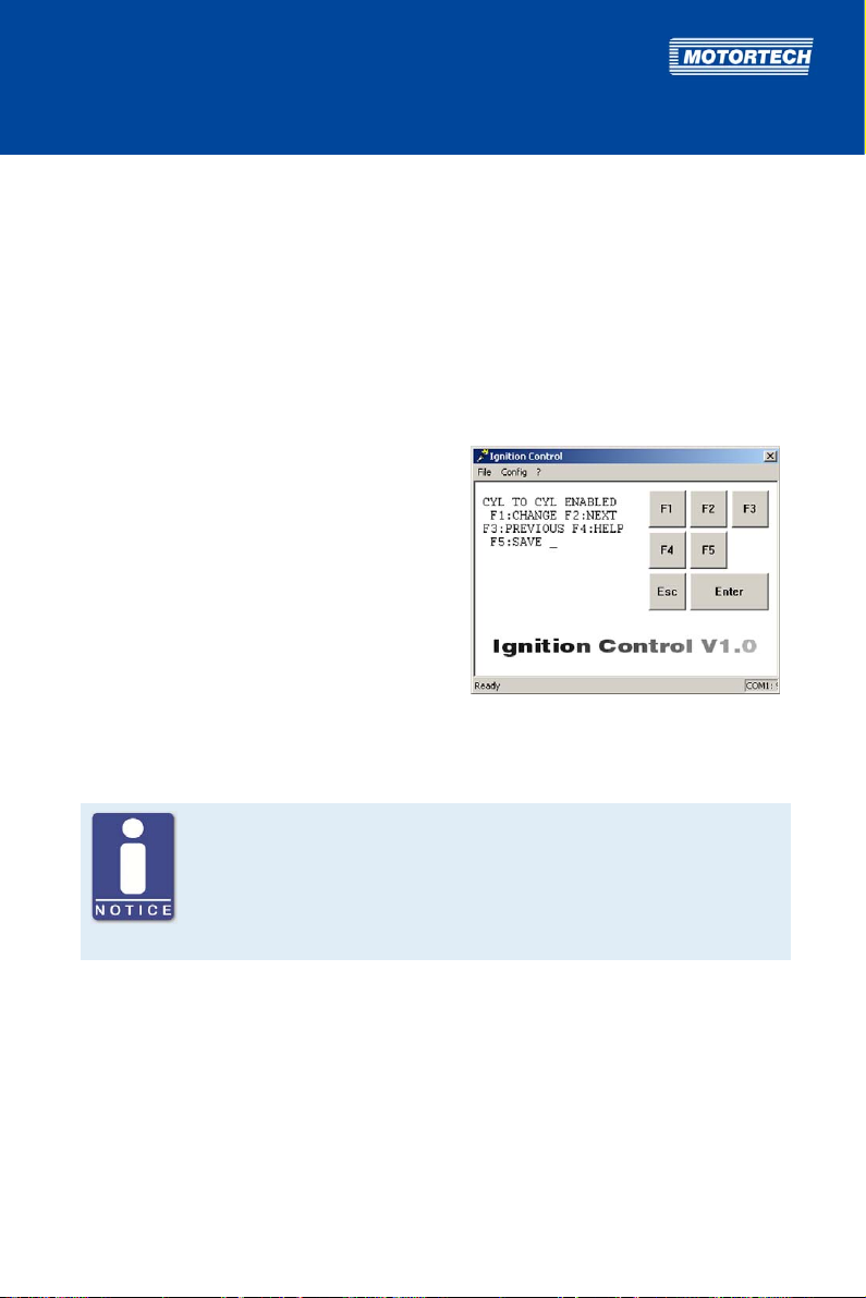
8.5.8 Activate Cylinder-to-Cylinder Alignment
With the CYL TO CYL parameter, you can activate the cylinder-to-cylinder alignment. This
optimizes the ignition timing of the individual cylinders based on your specifications. Ignition
timing optimization is carried out in a separate view outside the parameterization level. See
section Cylinder-to-Cylinder Alignment on page 103.
Possible values:
– ENABLE: Cylinder-to-cylinder alignment is activated.
– DISABLE: Cylinder-to-cylinder alignment is deactivated.
Proceed as follows:
Open parameterization level ->
[F2] to CYL TO CYL -> [F1] ->
Set with [F1] to ENABLE
or with [F2] to DISABLE -> [F5]
8.5.9 Select Function for Digital Input
No digital input at P/N 06.00.513
The device type P/N 06.00.513 is designed as a replacement for the ignition
controller Caterpillar® 163-6164. Thus, the device does not have the digital
input (Switch A/B, Switch Start/Stop) as described in this operating manual.
With this device type, schedule A settings are applied solely for ignition
timing configuration.
The function of the digital input is set by the CONTACT I/P parameter. You can choose from the
following functions:
– FOR STOP: The digital input is set to the Switch Start/Stop function and is used to switch on
and off the ignition. The ignition controller only applies schedule A in this configuration. For
more information, read the section Remote-Controlled Ignition Release on page 58.
– FOR A/B: The digital input is set to the Switch A/B function and is used to switch back and
forth between schedules A and B. For more information, read the section Schedules A/B on
page 59.
Rev. 01/2015 87
Page 88
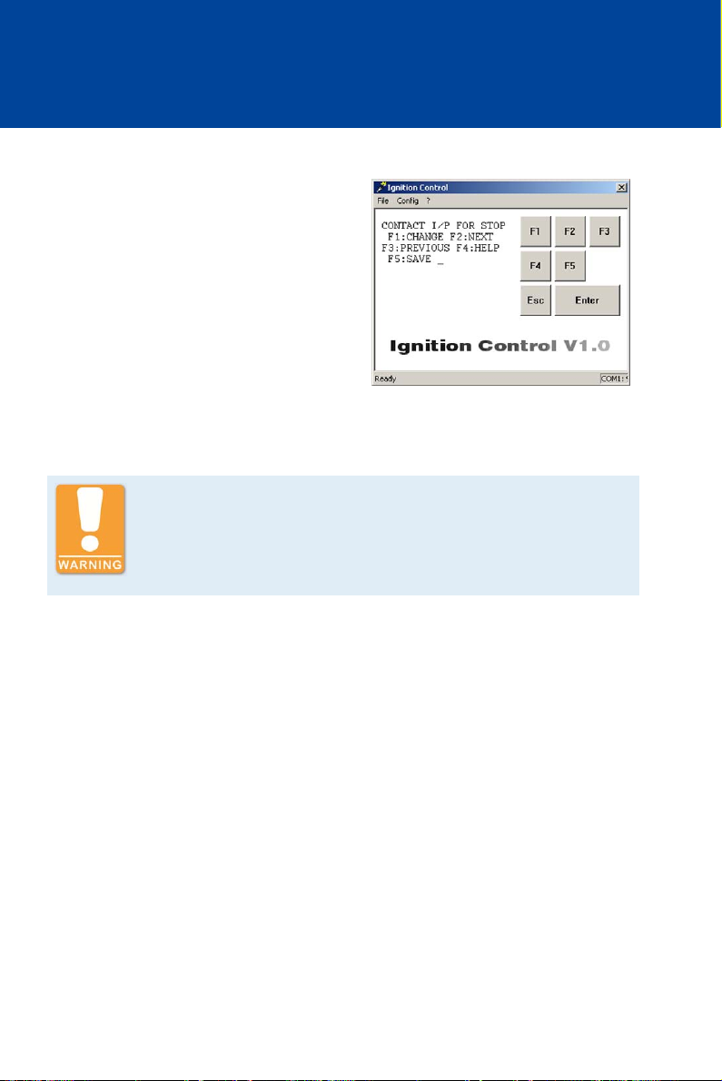
8 ADJUSTMENTS
Proceed as follows:
Open parameterization level ->
[F2] to CONTACT I/P -> [F1] ->
Set with [F1] to FOR STOP
or with [F2] to FOR A/B -> [F5]
8.5.10 Activate Potentiometer
Explosion hazard!
Never remove the cover for timing adjustment, unless the system is not
located in an explosive environment.
Reinsert the cover after every ignition timing adjustment made using the
potentiometer.
With the POT TIMING parameter, you can deactivate the potentiometer at the ignition controller
to avoid unauthorized changes in timing. Please observe that when the potentiometer is
deactivated, the potentiometer's timing setting will also be ignored, and all other ignition timing
adjustments will have the angle 0° BTDC added, regardless of the potentiometer's limits.
Possible values:
– ENABLE: The potentiometer of the ignition controller is activated. All other ignition
timing adjustments will be added to the ignition timing adjustment of the
potentiometer.
– DISABLE: The potentiometer of the ignition controller is deactivated. The angle 0° BTDC
is added to all other ignition timing adjustments.
88 Rev. 01/2015
Page 89
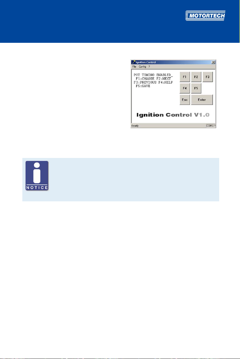
Proceed as follows:
Open parameterization level ->
[F2] to POT TIMING -> [F1] ->
Set with [F1] to ENABLE
or with [F2] to DISABLE -> [F5]
8.5.11 Activate Functions for Schedules A and B
No digital input at P/N 06.00.513
The device type P/N 06.00.513 is designed as a replacement for the ignition
controller Caterpillar® 163-6164. Thus, the device does not have the digital
input (Switch A/B, Switch Start/Stop) as described in this operating manual.
With this device type, schedule A settings are applied solely for ignition
timing configuration.
For both schedules, you can activate the SPEED CURVE and the ignition timing adjustment via
the 4-20 mA input.
Schedule B can only be used by a master control if you select the function Switch A/B for the
digital input (see Select Function for Digital Input on page 87).
The conduct of the speed curve and the 4-20 mA signal is defined in further settings, which, if
activated, apply equally to schedule A and B. For more information, read section Set Speed Curve
on page 97 and Set Limits for 4-20 mA Input on page 95.
Possible values:
– IN A/IN B: The respective parameter (SPEED CURVE or 4-20) is activated in schedule A or
B.
– NOT IN A/NOT IN B: The respective parameter (SPEED CURVE or 4-20) is deactivated in
schedule A or B.
Rev. 01/2015 89
Page 90
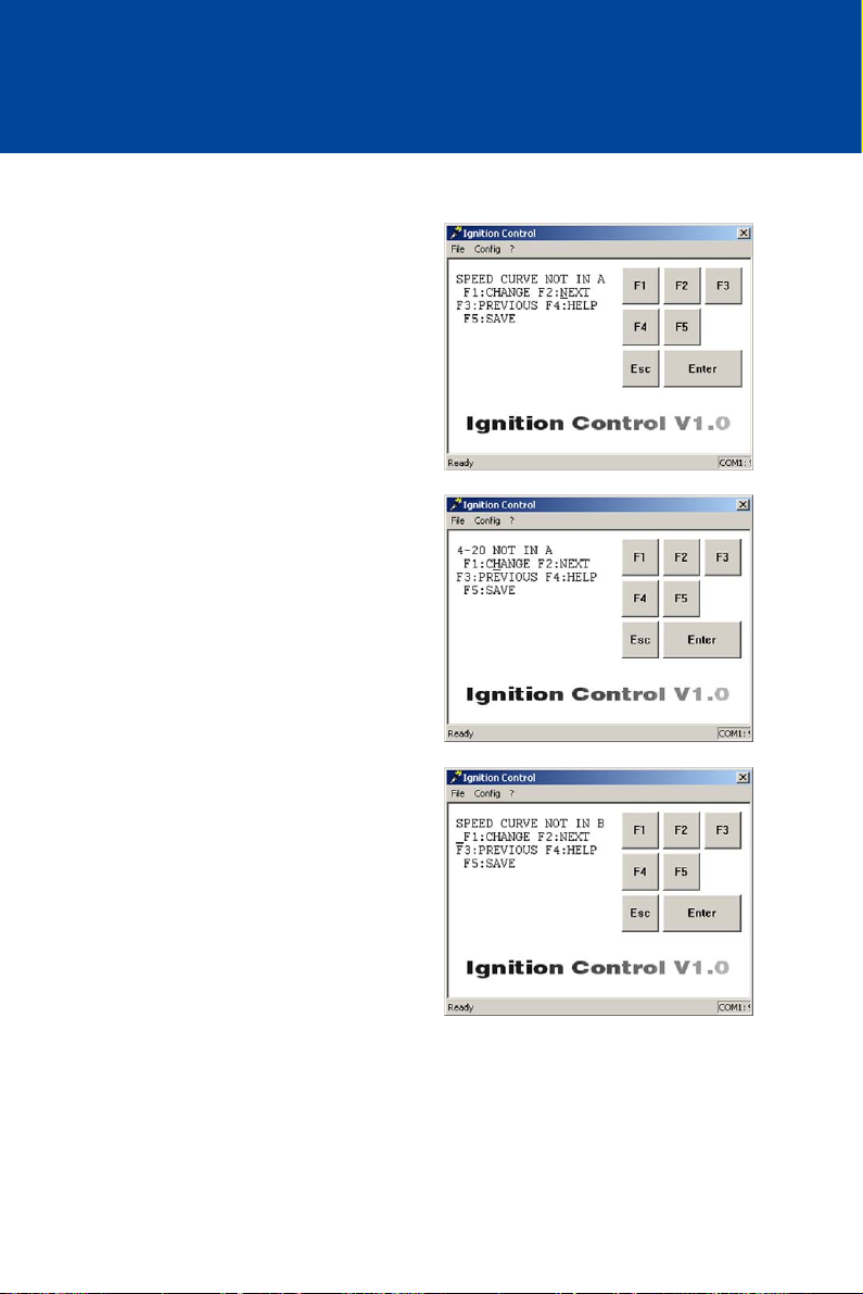
8 ADJUSTMENTS
Proceed as follows:
Activate Speed Curve for Schedule A
Open parameterization level ->
[F2] to SPEED CURVE IN A/NOT IN A -> [F1] ->
Set with [F1] to IN A
or with [F2] to NOT IN A -> [F5]
Activate 4-20 mA Input for Schedule A
Open parameterization level ->
[F2] to 4-20 IN A/NOT IN A-> [F1] ->
Set with [F1] to IN A
or with [F2] to NOT IN A -> [F5]
Activate Speed Curve for Schedule B
Open parameterization level ->
[F2] to SPEED CURVE IN B/NOT IN B -> [F1] ->
Set with [F1] to IN B
or with [F2] to NOT IN B -> [F5]
90 Rev. 01/2015
Page 91
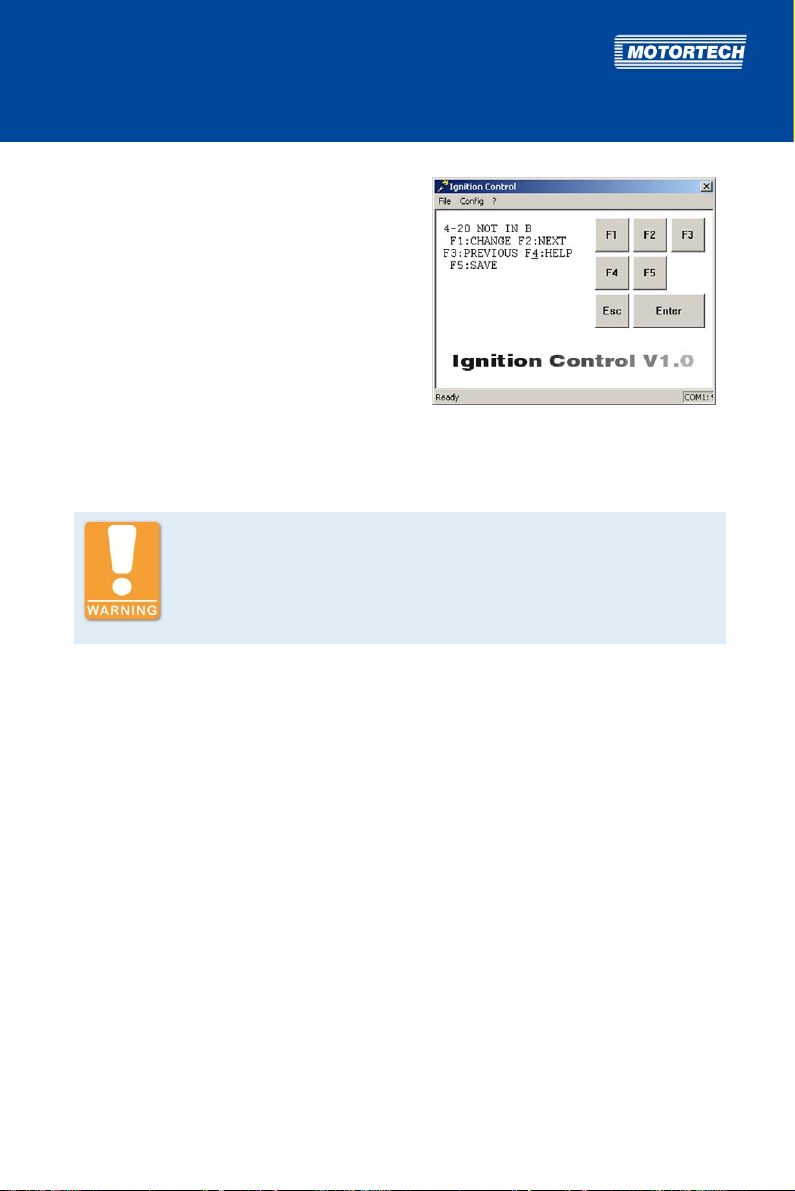
Activate 4-20 mA Input for Schedule B
Open parameterization level ->
[F2] to 4-20 IN B/NOT IN B-> [F1] ->
Set with [F1] to IN B
or with [F2] to NOT IN B -> [F5]
8.5.12 Set Potentiometer Limits
Explosion hazard!
Never remove the cover for timing adjustment, unless the system is not
located in an explosive environment.
Reinsert the cover after every ignition timing adjustment made using the
potentiometer.
You can define the range, within which the ignition timing can be adjusted with the
potentiometer of the ignition controller, with the POT CCW and POT CW parameters. The rotation
direction is determined by the values of both parameters. It is only possible to set values in the
advance direction (ADV).
The current potentiometer setting is only applied if the potentiometer is activated (see Activate
Potentiometer on page 88). The setting range applies equally to schedule A and B.
Value range:
– 0.00 to 58.00 with up to two decimal places
Enter decimal places with a period as the delimiter, e.g. 35.55.
Rev. 01/2015 91
Page 92
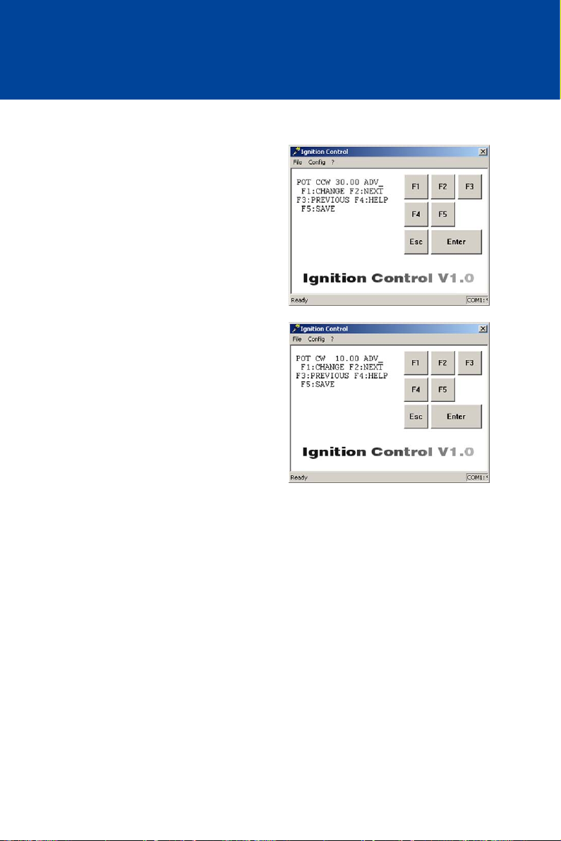
8 ADJUSTMENTS
Proceed as follows:
Define Left Potentiometer Stop
Open parameterization level ->
[F2] to POT CCW -> [F1] ->
Enter left potentiometer stop ->
[Enter] -> [F5]
Define Right Potentiometer Stop
Open parameterization level ->
[F2] to POT CCW -> [F1] ->
Enter right potentiometer stop ->
[Enter] -> [F5]
92 Rev. 01/2015
Page 93
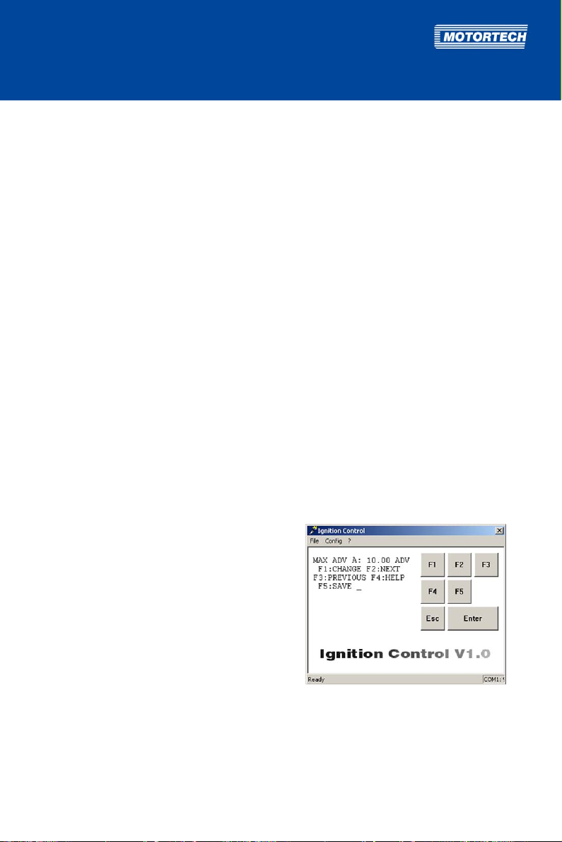
8.5.13 Set Ignition Timing Limits
To prevent engine damage caused by the addition of various parameters in the ignition timing
adjustment, you can set limits which may not be exceeded for ignition timing. MAX ADV
indicates the earliest possible firing time, MAX RET the latest possible firing time. Ignition timing
adjustments which extend beyond these limits will only be applied up to the set limit.
The limits are specified separately for the two schedules.
The limits for schedule B can only be configured if you select the function Switch A/B for the
digital input (see Select Function for Digital Input on page 87).
Value range:
– The maximum possible range of the ignition timing limits is 38°.
– The earliest possible timing (MAX ADV) must be at least 2° later than the reset position
(parameter Reset BTDC, see Set Reset Position on page 84).
– The latest possible timing (MAX RET) may not be more than 40° later than the reset
position (parameter Reset BTDC).
If Reset BTDC is set at 50°, the ignition timing limit must be set within the range of
10° BTDC to 48° BTDC. Values later than 10° are not possible.
– The value for the earliest ignition timing (MAX ADV) must be equal to or earlier than the
value for the latest ignition timing (MAX RET).
– Ignition timing limits ATDC cannot be set.
– Values may have up to two decimal places.
Enter decimal places with a period as the delimiter, e.g. 35.55.
Proceed as follows:
Set Earliest Ignition Timing for Schedule A
Open parameterization level ->
[F2] to MAX ADV A -> [F1] ->
Enter earliest ignition timing ->
[Enter] -> [F5]
Rev. 01/2015 93
Page 94
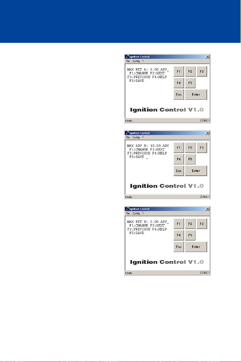
8 ADJUSTMENTS
Set Latest Ignition Timing for Schedule A
Open parameterization level ->
[F2] to MAX RET A -> [F1] ->
Enter latest ignition timing ->
[Enter] -> [F5]
Set Earliest Ignition Timing for Schedule B
Open parameterization level ->
[F2] to MAX ADV B -> [F1] ->
Enter earliest ignition timing ->
[Enter] -> [F5]
Set Latest Ignition Timing for Schedule B
Open parameterization level ->
[F2] to MAX RET B -> [F1] ->
Enter latest ignition timing ->
[Enter] -> [F5]
94 Rev. 01/2015
Page 95
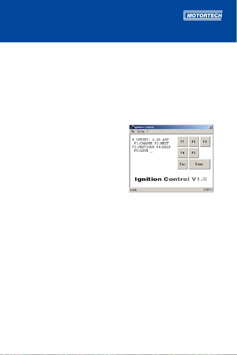
8.5.14 Set Timing Offset for Schedule B
With the B OFFSET parameter, you can set an ignition timing offset to offset the ignition timing
for active schedule B (= digital input is closed) in addition to all other timing adjustments.
This function is only available if the digital input is set to the Switch A/B function, and therefore
switching between both schedules is enabled (see Select Function for Digital Input on page 87).
Value range:
– 40.00 ADV (advance) to 40.00 RET (retard) with up to two decimal places
Enter decimal places with a period as the delimiter, e.g. 35.55.
Proceed as follows:
Open parameterization level ->
[F2] to B OFFSET -> [F1] ->
Enter timing offset -> [Enter] ->
Select [F1] for ADVANCE
or [F2] for RETARD -> [F5]
8.5.15 Set Limits for 4-20 mA Input
In order to set limits for the 4-20 mA input, the 4-20 mA input must be activated for at least one
of the schedules A or B (see Activate Functions for Schedules A and B on page 89).
If the 4-20 mA input is activated, you have the possibility of adjusting the ignition timing via an
external analog 4-20 mA signal.
Via the 4 mA value (parameter 4mA TIMING) and the 20 mA value (parameter 20mA TIMING), you
can specify the span for the ignition timing adjustment. For the signals between 4 and 20 mA,
the adjustment is calculated linearly towards the 20 mA value. Please refer to the example at the
end of the section.
With the parameter DFLT 4-20, you additionally define an ignition timing adjustment in case the
ignition controller detects no signal (e.g. due to a broken wire) or the incoming signal undercuts
4 mA.
Value ranges:
– 40.00 ADV (advance) to 40.00 RET (retard) with up to two decimal places
Enter decimal places with a period as the delimiter, e.g. 35.55.
– The values for 4mA TIMING and 20mA TIMING may not differ more than 40°.
Rev. 01/2015 95
Page 96
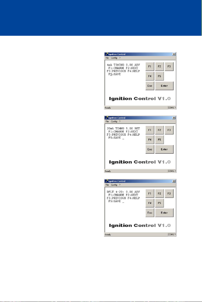
8 ADJUSTMENTS
Proceed as follows:
Enter Ignition Timing Adjustment at 4 mA
Open parameterization level ->
[F2] to 4mA TIMING -> [F1] ->
Enter ignition timing adjustment ->
[Enter] -> Select [F1] for ADVANCE
or [F2] for RETARD -> [F5]
Enter Ignition Timing Adjustment at 20 mA
Open parameterization level ->
[F2] to 20mA TIMING -> [F1] ->
Enter ignition timing adjustment ->
[Enter] -> Select [F1] for ADVANCE
or [F2] for RETARD -> [F5]
Enter Ignition Timing Adjustment in the Event of
Signal Loss
Open parameterization level ->
[F2] to DFLT 4-20 -> [F1] ->
Enter ignition timing adjustment ->
[Enter] -> Select [F1] for ADVANCE
or [F2] for RETARD -> [F5]
96 Rev. 01/2015
Page 97
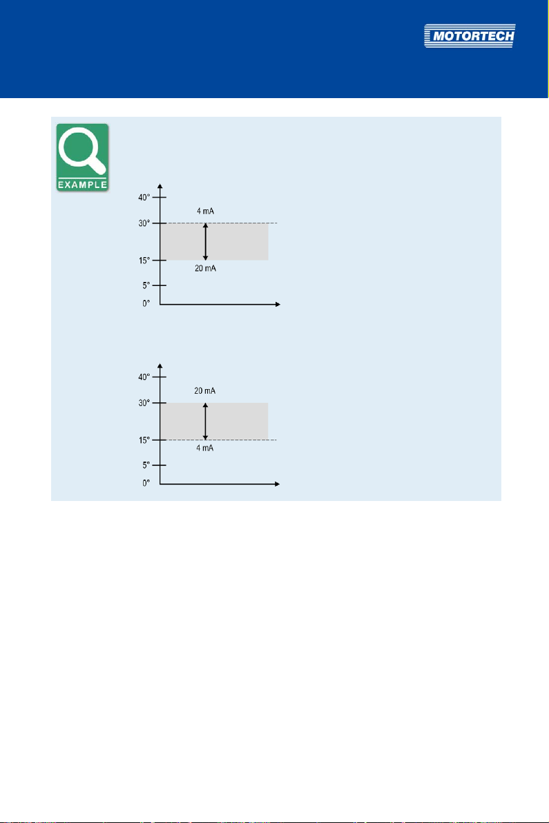
Configuration examples
Characteristic 4-20 mA – ignition timing adjustment towards retard
BTDC
Parameterization
4mA TIMING: 0.00 ADV
20mA TIMING: 15.00 RET
15° retarded ignition if timing is at
30° BTDC
t
Characteristic 4-20 mA – ignition timing adjustment towards advance
BTDC
Parameterization
4mA TIMING: 0.00 ADV
20mA TIMING: 15.00 ADV
15° advanced ignition if timing is at
15° BTDC
t
8.5.16 Set Speed Curve
The speed curve enables the adjustment of the ignition timing based on the speed of the engine.
You can configure the speed curve as soon as you have activated it for schedule A or B (see
Activate Functions for Schedules A and B on page 89). The setting for schedule B will only be
applied if the digital input in the Function switch A/B allows a switch between the two schedules
(see Select Function for Digital Input on page 87).
With the parameter # SPEED POINTS, you can specify the number of desired points in the speed
curve. There is a maximum of five points possible. For each point (BP1 to max. BP5) you can
specify a speed value (NEW SPEED) and the corresponding timing adjustment (NEW ANGLE).
Please also refer to the example at the end of the section.
You can only configure the same amount of speed points (BPx) as you set up under # SPEED
POINTS.
Rev. 01/2015 97
Page 98
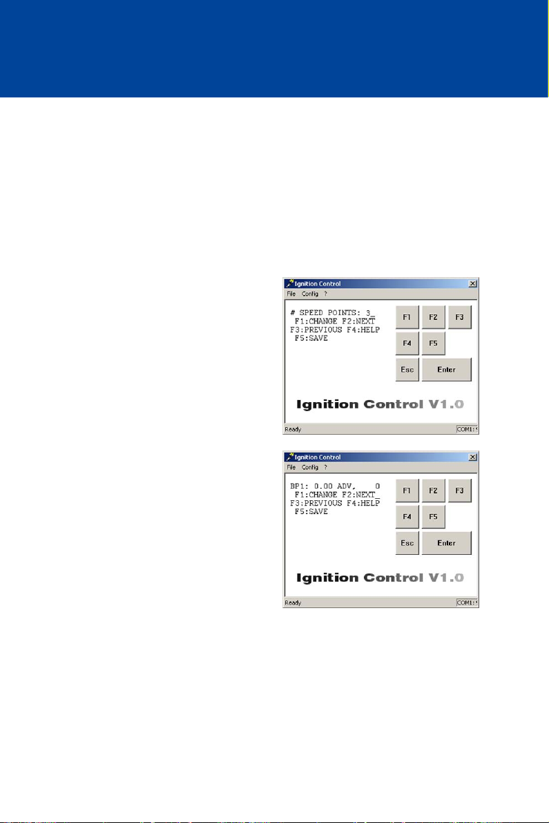
8 ADJUSTMENTS
Value ranges:
– # SPEED POINTS: 0 to 5, whole numbers
If you enter the value for the # SPEED POINTS parameter, then there is no speed
curve activated and therefore no speed points can be configured.
– NEW SPEED: 0 to 5000, whole numbers
– NEW ANGLE: 40.00 ADV (advance) to 40.00 RET (retard) with up to two decimal places
Enter decimal places with a period as the delimiter, e.g. 35.55.
Proceed as follows:
Specify Number of Speed Points
Open parameterization level ->
[F2] to # SPEED POINTS -> [F1] ->
Enter number of speed points ->
[Enter] -> [F5]
Define Speed Point
Open parameterization level ->
[F2] to to desired speed point BPx (e.g. BP1) ->
[F1] -> Enter speed value (NEW SPEED) ->
[Enter] -> Enter ignition timing adjustment
(NEW ANGLE) -> [Enter] ->
Select [F1] for ADVANCE
or [F2] for RETARD -> [F5]
(x=desired speed point)
98 Rev. 01/2015
Page 99
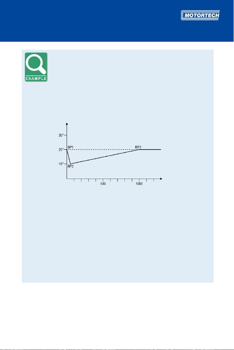
Speed Curve
Example of a typical speed curve for an engine in generator mode, for which
the speed curve is intended to positively impact the start performance of
the engine:
If the engine is not running, the timing is equivalent to the potentiometer
setting, as in example 20° BTDC. When the engine is started, the ignition
timing is reduced by 10° and above 50 revolutions it increases again, until it
reaches the specified final value at 1000 revolutions.
Timing
BTDC
Potentiometer
adjustment
rpm
To define the speed curve, the following values are set in parameterization:
Number of speed points
# SPEED POINTS: 3
Definition of the three speed points
BP1 NEW SPEED 0 No ignition timing adjustment
NEW ANGLE 0 ADV
BP2 NEW SPEED 50 Ignition timing adjustment
NEW ANGLE 10 RET
by 10° retard
BP3 NEW SPEED 1000 No ignition timing adjustment
NEW ANGLE 0 ADV
Rev. 01/2015 99
Page 100
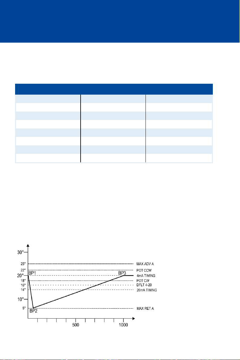
8 ADJUSTMENTS
8.5.17 Configuration Example
The following configuration example serves to demonstrate the functionality of the MIC500
ignition controller and the effect of the individual parameter settings.
Sample Values
Parameter Value Parameter Value Parameter Value
RESET BTDC 30° POT CW 18° ADV DFLT 4-20 4° RET
CONTACT I/P FOR A/B MAX ADV A 25° ADV # SPEED POINTS 3
POT TIMING ENABLED MAX RET A 5° ADV BP1 SPEED 0 RPM
SPEED CURVE A IN A MAX ADV B 23° ADV BP1 ANGLE 0° ADV
4-20 A IN A MAX RET B 3° ADV BP2 SPEED 50 RPM
SPEED CURVE B IN B B OFFSET 2° RET BP2 ANGLE 15° RET
4-20 B IN B 4mA TIMING 0° RET BP3 SPEED 1000 RPM
POT CCW 22° ADV 20mA TIMING 6° RET BP3 ANGLE 0° ADV
Schedule A
The setting CONTACT I/P=FOR A/B enables the digital input to switch back and forth between
schedule A and B.
Schedule A is active if the digital input is open. The possible timing settings are limited with
MAX ADV A and MAX RET A to values between 25° BTDC and 5° BTDC. With a potentiometer
setting of 20 BTDC and a signal of 4 mA via the 4-20 mA input, the above configuration example
has the following effect:
Timing
BTDC
rpm
100 Rev. 01/2015
 Loading...