

Page 1
MIC5 – Ignition Controller
Operating Manual
P/N 01.10.023-EN | Rev. 03/2019
Page 2

Original instructions
Copyright
© Copyright 2019 MOTORTECH GmbH. All rights reserved.
Distribution and reproduction of this publication or parts thereof, regardless of the specific
purpose and form, are not permissible without express written approval by MOTORTECH.
Information contained in this publication may be changed without prior notice.
Trademarks
MOTORTECH products and the MOTORTECH logo are registered and/or common law trademarks
of the MOTORTECH GmbH. All further trademarks and logos displayed or used in this publication
are the property of the respective entitled person.
Page 3

Table of Contents
1 General Information .................................................................................................... 8
1.1 What Is the Purpose of this Operating Manual? ......................................................... 8
1.2 Who Is this Operating Manual Targeted to? ............................................................... 8
1.3 Which Symbols Are Used in the Operating Manual? ................................................... 8
1.4 Which Abbreviations/Acronyms Are Used in the Operating Manual? ........................... 9
2 Safety Instructions .................................................................................................... 11
2.1 General Safety Instructions .................................................................................... 11
2.2 Electrostatic Discharge Hazards ............................................................................ 12
2.3 Information on Electric Isolation ............................................................................ 13
2.4 Special Safety Instructions for the Device .............................................................. 14
2.5 Proper Disposal .................................................................................................... 16
3 Intended Use ............................................................................................................. 17
3.1 Functional Description .......................................................................................... 17
3.2 Applications ......................................................................................................... 17
4 Product Description ................................................................................................... 18
4.1 Technical Data ...................................................................................................... 18
4.1.1 Certifications ..................................................................................................... 18
4.1.2 Mechanical Data ................................................................................................ 19
4.1.3 Warning Notices on the Device ............................................................................ 20
4.1.4 Product Identification – Labeling on the Device .................................................... 21
4.1.5 Electrical Data .................................................................................................... 21
4.1.6 Interfaces .......................................................................................................... 25
4.1.7 Requirements for External Equipment .................................................................. 26
4.1.8 Overview Drawings ............................................................................................ 27
4.1.9 LEDs and Connections ........................................................................................ 30
5 Installation Instructions ............................................................................................. 32
5.1 Unpacking ............................................................................................................ 32
5.2 Installation of the Ignition Controller ..................................................................... 32
5.2.1 Installation of the Vibration Dampers .................................................................. 33
5.2.2 Installation of the Ground Strap .......................................................................... 34
5.3 Determine the Installation Location of the Pickup ................................................... 35
6 Wiring of the Device ...................................................................................................36
6.1 Input and Output Wiring on the Controller .............................................................. 36
6.1.1 Input Wiring ....................................................................................................... 37
6.1.2 Input Wiring – Power Supply ............................................................................... 39
Rev. 03/2019 3
Page 4

Table of Contents
6.1.3 Input Wiring – Pickups ....................................................................................... 41
6.1.4 Input Wiring – Timing and Safety Devices ............................................................ 43
6.1.5 Output Wiring – Binary Outputs (Go/NoGo, GPO, ASO) ......................................... 46
6.1.6 Wiring – PowerView3 ......................................................................................... 47
6.1.7 Output Wiring – CAN Bus Interface ...................................................................... 49
6.1.8 Output Wiring – RS485 Interface ..........................................................................51
6.2 Ignition Coil Wiring ............................................................................................... 53
6.2.1 Ignition Coil Wiring for a 35-Pole Connector ......................................................... 54
6.2.2 Ignition Coil Wiring 17-Pole and 14-Pole Connector .............................................. 55
6.2.3 Straight Order Wiring of the Ignition Outputs ...................................................... 56
6.2.4 Straight Order Wiring of the Ignition Outputs – Overview ..................................... 57
7 Functions ................................................................................................................... 59
7.1 Pickup Sensitivity ................................................................................................. 59
7.2 Monitoring of Pickup Signals ................................................................................. 59
7.3 Go/NoGo .............................................................................................................. 59
7.4 Ignition Timing Adjustment ................................................................................... 60
7.4.1 Manual Timing Correction ................................................................................... 62
7.4.2 Analog Inputs .................................................................................................... 62
7.4.3 Cylinder-to-Cylinder Alignment ........................................................................... 64
7.4.4 Speed Curve ...................................................................................................... 64
7.4.5 Ignition Timing Correction .................................................................................. 64
7.5 Firing Angles ........................................................................................................ 64
7.6 HV-Power Supply Error Monitoring ......................................................................... 64
7.7 Output Monitoring ................................................................................................ 65
7.8 Schedules A/B ..................................................................................................... 65
7.9 Alarms ................................................................................................................. 65
7.10 GPO: General Purpose Output .............................................................................. 66
7.11 ASO: Auxiliary Synchronization Output ................................................................. 66
7.12 Ignition Energy ................................................................................................... 68
7.13 Access Control .................................................................................................... 68
8 Settings via the MICT ................................................................................................. 70
8.1 MICT System Requirements ................................................................................... 70
8.2 MICT Installation .................................................................................................. 70
8.3 Access Levels in the MICT ...................................................................................... 71
8.4 Configuration Pages (Overview) ............................................................................ 72
8.5 Menu Bar and Toolbar........................................................................................... 73
8.6 Online Update Settings ........................................................................................ 76
4 Rev. 03/2019
Page 5

Table of Contents
8.7 Self Test............................................................................................................... 77
8.8 Pickup Trace ........................................................................................................ 78
8.9 Access Control for MIC5 ........................................................................................ 81
8.9.1 Enable/Disable Access Control ........................................................................... 81
8.9.2 Login/Logout .................................................................................................... 82
8.9.3 Changing the PIN ............................................................................................... 82
8.9.4 Reset all PINs .................................................................................................... 82
8.10 Working with Configurations ............................................................................... 83
8.10.1 Create, Open, Save ........................................................................................... 84
8.10.2 Upload, Download ........................................................................................... 85
8.10.3 Compatibility Information ................................................................................. 86
8.11 Configuration ...................................................................................................... 87
8.11.1 Engine – Parameters ......................................................................................... 88
8.11.2 Engine – Cylinder Names .................................................................................. 91
8.11.3 Engine – Ignition Outputs ................................................................................. 92
8.11.4 Engine – Ignition Coils ...................................................................................... 94
8.11.5 Engine – Pickups .............................................................................................. 96
8.11.6 Timing – Analog Inputs ................................................................................... 100
8.11.7 Timing – Schedule A/B – General .................................................................... 102
8.11.8 Timing – Schedule A/B – Energy ..................................................................... 104
8.11.9 Timing – Miscellaneous .................................................................................. 105
8.11.10 Inputs/Outputs – Alarms ............................................................................... 106
8.11.11 Inputs/Outputs – ASO1 (Auxiliary Synchronization Output) .............................. 108
8.11.12 Inputs/Outputs – Inputs ................................................................................. 110
8.11.13 Miscellaneous – Communication .................................................................... 111
8.11.14 Miscellaneous – Information .......................................................................... 113
8.12 Runtime Data ..................................................................................................... 114
8.12.1 Runtime Data – Overview ................................................................................. 115
8.12.2 Runtime Data – Timing .................................................................................... 118
8.12.3 Runtime Data – Ignition ................................................................................... 119
8.12.4 Runtime Data – Bank A and B .......................................................................... 120
8.12.5 Runtime Data – States .................................................................................... 122
8.12.6 Runtime Data – Message Log .......................................................................... 128
8.12.6.1 Information ................................................................................................. 130
8.12.6.2 Warnings .................................................................................................... 133
8.12.6.3 Alarms ....................................................................................................... 134
8.12.6.4 Failure ........................................................................................................ 134
Rev. 03/2019 5
Page 6

Table of Contents
8.12.7 Runtime Data – Diagnostics ............................................................................ 138
8.12.8 Runtime Data – Temperatures ........................................................................ 140
8.12.9 Runtime Data – Information ............................................................................. 141
8.13 Log .................................................................................................................. 142
8.14 Runtime Adjustments ........................................................................................ 143
8.14.1 Runtime Adjustments – Reset ......................................................................... 144
8.14.2 Runtime Adjustments – Timing ........................................................................ 145
8.14.3 Runtime Adjustments – Energy ....................................................................... 146
8.14.4 Runtime Adjustments – Secondary Voltage Estimation Calibration ..................... 147
8.14.5 Runtime Adjustments – Secondary Short Calibration ........................................ 148
8.15 Cylinder Individual Offsets ................................................................................ 149
8.16 Schedule Curve ................................................................................................. 151
8.16.1 Schedule Curve – Simulation ........................................................................... 151
8.16.2 Schedule Curve – Runtime Values .................................................................... 153
8.17 Coils ................................................................................................................. 154
8.17.1 General ........................................................................................................... 155
8.17.2 Min. Energy Limit Curve ................................................................................... 157
9 Operation ................................................................................................................ 158
9.1 Start-up ..............................................................................................................158
9.2 Shutdown ...........................................................................................................158
9.3 Firmware Update ................................................................................................. 159
10 Errors ..................................................................................................................... 163
10.1 Possible Faults .................................................................................................. 163
10.2 Causes of Faults ............................................................................................... 163
10.2.1 Overspeed ..................................................................................................... 163
10.2.2 Output Error Detection ................................................................................... 163
10.2.3 Misfire Detection (Primary) ............................................................................. 163
10.2.4 Pickup Input Errors ......................................................................................... 164
10.2.5 Acknowledging Faults .................................................................................... 164
10.3 Troubleshooting ................................................................................................ 165
10.3.1 Running a Self Test .......................................................................................... 165
10.3.2 Customer Service Information .......................................................................... 165
10.3.3 Returning Equipment for Repair/Inspection ...................................................... 165
10.3.4 Instructions for Packaging the Equipment ........................................................ 166
6 Rev. 03/2019
Page 7

Table of Contents
11 Maintenance ........................................................................................................... 167
11.1 Maintenance Instructions ................................................................................... 167
11.2 Spare Parts and Accessories .............................................................................. 167
12 Index ..................................................................................................................... 168
Rev. 03/2019 7
Page 8

1 General Information
Read through this operating manual carefully before use and become familiar with the product.
Installation and start-up should not be carried out before reading and understanding this
document. Keep this manual readily available so that you can reference it as needed.
1.1 What Is the Purpose of this Operating Manual?
This manual serves as an aid for the installation and operation of the product and supports the
technical staff with all operating and maintenance tasks to be performed. Furthermore, this
manual is aimed at preventing dangers to life and health of the user and third parties.
1.2 Who Is this Operating Manual Targeted to?
The operating manual provides a code of conduct for personnel tasked with the setup,
operation, maintenance, and repair of gas engines. A certain level of technical knowledge with
respect to the operation of gas engines and basic knowledge of electronic ignition systems are
necessary. Persons who are only authorized to operate the gas engine shall be trained by the
operating company and shall be expressly instructed concerning potential hazards.
1.3 Which Symbols Are Used in the Operating Manual?
The following symbols are used in this manual and must be observed:
Example
This symbol indicates examples, which point out necessary handling steps
and techniques. In addition, you receive additional information from the
examples, which will increase your knowledge.
Notice
This symbol indicates important notices for the user. Follow these. In
addition, this symbol is used for overviews that give you a summary of the
necessary work steps.
Warning
This symbol indicates warnings for possible risks of property damage or
risks to health. Read these warning notices carefully and take the
mentioned precautionary measures.
8 Rev. 03/2019
Page 9

1 General Information
Danger
This symbol indicates warnings for danger to life, especially due to high
voltage. Read these warning notices carefully and take the mentioned
precautionary measures.
1.4 Which Abbreviations/Acronyms Are Used in the Operating Manual?
In the manual or the user interface, the following abbreviations / acronyms are used.
Abb. Term Description Explanation
ADV Advance Advanced with respect
to top dead center
ASO Auxiliary
Output for synchronizing the
Synchronization Output
ATDC After Top Dead Center
BTDC Before Top Dead Center
CAN bus Controller Area Network
bus
Bus for control
devices/networks
CE Conformité Européenne Conformity with EU
directives
CPU Central Processing Unit
°crankshaft Degree crankshaft Unit for the rotation angle of
CSA Canadian Standards
Organization that defines
Association
DC Direct Current
DetCon Detonation Control
Serves to prevent major
System
Indicates the direction for
timing
MIC5 and other controllers
Asynchronous serial
connection system for
linking control units
Mark based on EU
legislation for certain
products in conjunction with
product safety
the crankshaft
standards, inspects
products for safety
compliance, and issues
pertinent certifications.
engine damage that can be
caused by knocking
combustion.
Rev. 03/2019 9
Page 10

1 General Information
Abb. Term Description Explanation
EMI Electromagnetic
EMC Electromagnetic
GPI General Purpose Input Multi-purpose input
GPO General Purpose Output Multi-purpose output
HV High Voltage
ISO International
LED Light Emitting Diode Light emitting electronic
MIC MOTORTECH Ignition
MICT MOTORTECH Integrated
MOSFET Metal Oxide
PG Panzergewinde Panzer screw thread Screw thread type for cable
POT Potentiometer Continuously adjustable
PWR Power Output/current
RET Retard Retarded with respect
RS485/
TIA485
TDC Top Dead Center
USB Universal Serial Bus Serial connection system to
Interference
Compatibility
Organization for
Standardization
Controller
Configuration Tool
Semiconductor
Field-Effect Transistor
Recommended Standard
485/
Telecommunications
Industry Association 485
Compatibility of electrical or
Software for the
Semiconductor component
to the top dead center
Industrial standard for a
electronic equipment items
with their surroundings
semiconductor
configuration of the MIC5
screw connections
potential divider
Indicates the direction for
timing
physical interface for
asynchronous serial data
transfer
link a computer to external
devices
10 Rev. 03/2019
Page 11

2 Safety Instructions
2.1 General Safety Instructions
The following safety instructions must be followed in the area in which the device is operated:
High voltage! Danger to life!
While the engine is running, the area around the ignition system especially
holds the risk of danger due to high voltage. The following parts should
therefore not be touched or removed unless explicitly stated otherwise:
– Ignition coils and caps
– Wires of the high voltage circuit
– In- and output wiring of the ignition controller
– Pickups and their wiring
Danger to persons with pacemakers!
Electromagnetic impulses in the wiring of the ignition system may exceed
the permissible limits of pacemakers. Persons with pacemakers must
MOTORTECH equipment is manufactured as state of the art and therefore safe and reliable to
operate. Nevertheless the equipment can cause risks or damage can occur, if the following
instructions are not complied with:
– The gas engine must only be operated by trained and authorized personnel.
– Operate the equipment only within the parameters specified in the technical data.
– Use the equipment correctly and for its intended use only.
– Never apply force.
– For all work such as installation, conversion, adaptation, maintenance, and repair, all
equipment must be disconnected from the mains and secured against unintentional
reactivation.
– Perform only such maintenance and repair work as is described in this operating manual,
and follow the instructions given while working.
– Only use spare parts supplied by MOTORTECH for the maintenance of the device.
– Further work must only be performed by personnel authorized by MOTORTECH.
Non-compliance with the instructions will void any warranties for the proper function of the
equipment as well as the responsibility for the validity of the certifications.
– Safety devices must not be dismounted or disabled.
– Avoid all activities that can impair the function of the equipment.
therefore not be present in the vicinity of the ignition system being
operated. Mark the operating location of the ignition system with the
corresponding standardized warning symbol.
Rev. 03/2019 11
Page 12

2 Safety Instructions
– Operate the equipment only while it is in proper condition.
– Investigate all changes detected while operating the gas engine or ignition system.
– Ensure compliance with all laws, directives, and regulations applicable to the operation of
your system, including such not expressly stated herein.
– If the system is not entirely tight and sealed, gas may escape and result in explosion hazard.
The inhalation of gas can also lead to death or severe health damages. Therefore, upon
completion of all assembly works, always check the system's tightness.
– Always ensure adequate ventilation of the engine compartment.
– Ensure a safe position at the gas engine.
– There is a risk of burning on hot surfaces. Allow the engine to cool down before starting any
work.
– Personal protective equipment (PPE), e.g. safety shoes and gloves, must be worn during all
work on the engine.
– Your behavior can reduce possible residual risks to a minimum. Observe responsible
handling of the gas engine and the gas-carrying system.
2.2 Electrostatic Discharge Hazards
Electronic equipment is sensitive to static electricity. To protect these components from damage
caused by static electricity, special precautions must be taken to minimize or prevent
electrostatic discharge.
Observe these safety precautions while you work with the equipment or in its vicinity.
– Before performing maintenance or repair work, ensure that the static electricity inherent to
your body is discharged.
– Do not wear clothing made from synthetic materials to prevent static electricity from
building up. Your clothing should therefore be made of cotton or cotton mix materials.
– Keep plastics such as vinyl and Styrofoam materials as far away from the control system, the
modules, and the work environment as possible.
– Do not remove the circuit boards from the housing of the device.
12 Rev. 03/2019
Page 13

2 Safety Instructions
2.3 Information on Electric Isolation
If ground and earth potential are not properly isolated, the following problems as well as others
can occur:
– Electromagnetic interferences (e.g. ground loops)
– Signal corruption (e.g. of the analog voltage signal)
– Unwanted leakage currents
Therefore, earth potential and the negative pole of the power supply of all devices in the electric
assembly that provide the option, should be connected separately. If possible, the negative pole
of the power supply should only be connected to earth potential at one point in the entire
system.
Wiring Example
Device with
shielded wires
Device featuring
protection class II
Rev. 03/2019 13
Page 14
2 Safety Instructions
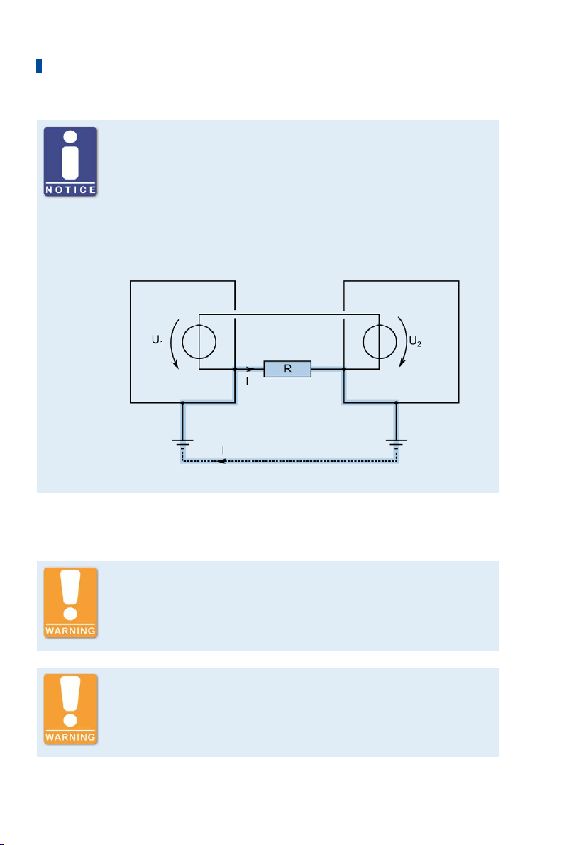
Occurrence of ground loops
The devices shown in the following image do not feature the possibility to
connect the earth potential and the negative pole of the power supply
separated from each other. How ground loops are created.
A ground loop is a ground connection of an electric wiring assembly that is
closed as a loop. Due to impedance (resistance R > ) of the loop,
low-frequency interference currents can lead to an unwanted voltage drop
in the signal path.
Device 1 Device 2
Ground loop
2.4 Special Safety Instructions for the Device
Explosion hazard!
Never open the device (e.g. by removing covers or the service screw). If the
system is located in a hazardous area, there is a risk of explosion.
Explosion hazard!
The replacement of parts or assemblies can impair compliance with CSA
Class I, Division 2 (Group C, D), T4.
14 Rev. 03/2019
Page 15
2 Safety Instructions
Explosion hazard!
Do not disconnect any connectors while the system is live. If the system is
located in a hazardous area, there is a risk of explosion.
Explosion hazard!
Never remove the equipment while the unit is connected to a power source.
If the system is located in a hazardous area, there is a risk of explosion.
Explosion hazard!
Do not remove or replace the fuse while the equipment is live.
Risk of burning!
The surfaces of the system may heat up to high temperatures.
Operational safety!
All connector screws and screw joints must be adequately tightened. Refer
to the section Mechanical Data on page 19.
After the service cover on the device has been opened, e.g. to complete the
wiring, it must be refitted so that it is in the same alignment as it was prior
to opening. The USB connection must always be below the service screw. If
the mounting is rotated, maintaining the indicated protection classes, as
well as compliance with CSA-Class I, Division 2 (Group C, D) is impaired.
Rev. 03/2019 15
Page 16

2 Safety Instructions
Operational safety
The correct operation of the device is only guaranteed if the device is
operated within the permissible supply voltage range. Therefore, use a
power supply according to the specifications in the operating instructions.
Risk of destruction!
Magnetic fields and heat occur when welding, which may damage or
destroy the MIC5. Therefore, pay attention to the following when welding:
– Disconnect all electrical connections to the MIC5 prior to welding.
– Protect the MIC5 against direct contact with the welding unit and
magnetic fields, sparks and liquid metal.
2.5 Proper Disposal
After the expiration of its service life, MOTORTECH equipment can be disposed of with other
commercial waste, or it may be returned to MOTORTECH. We will ensure its environmentally
friendly disposal.
16 Rev. 03/2019
Page 17

3 Intended Use
3.1 Functional Description
The devices of the MIC5 series are microprocessor controlled ignition systems, that are
comprised of one 32 bit main processor (CPU) and an output board.
Please note that the manufacturer is not required to implement configurations of the ignition
controller for specific engines, and that devices may be delivered without pertinent
configuration.
The ignition controllers of the MIC5 series use information supplied by the pickups to precisely
determine the correct timing for the respective outputs. The timing is influenced by various
inputs made either automatically or manually. This can be implemented with manual
potentiometers, the analog input signals, a speed characteristic, or with a serial interface (USB,
CAN bus, RS485).
During operation, the ignition controllers continuously monitor the system status of all installed
pickups and the correct operation of the primary ignition circuit by checking the information
received.
Depending on the severity of an error that is detected, the device will shut down immediately or
warn the operator. A corresponding message can be viewed on a connected PC.
To protect the engine, the ignition controllers additionally have an adjustable overspeed
shut-off.
3.2 Applications
The ignition controllers of the MIC5 series are designed for specific 2- or 4-stroke gas engines.
From 1 to max. 20 ignition outputs are available. The ignition controllers supply the energy
required for the corresponding ignition coils of the gas engines and can supply signals for
peripheral equipment.
Any use other than the one described in the operating manual shall be considered improper use
and will result in the voiding of all warranties.
Rev. 03/2019 17
Page 18

4 Product Description
4.1 Technical Data
4.1.1 Certifications
The ignition controllers of the MIC5 series are certified as per the following
directives/regulations:
CE
– EMC Directive 2014/30/EU
– EN 61326-1:2013 – Electrical equipment for measurement, control and laboratory use.
EMC requirements. General requirements
– EN 55011:2009 + A1:2010 – Industrial, scientific and medical equipment.
Radio-frequency disturbance characteristics. Limits and methods of measurement
– EN 61000-6-2:2005 + AC:2005 – Electromagnetic compatibility (EMC). Generic
standards. Immunity for industrial environments
– EN 61000-6-4:2007 + A1:2011 – Electromagnetic compatibility (EMC). Generic standards.
Emission standard for industrial environments
– Low Voltage Directive 2014/35/EU
– EN 61010-1:2010 – Safety requirements for electrical equipment for measurement,
control, and laboratory use. General requirements
– EN 60529:1991 + A1:2000 + A2:2013 – Degrees of protection provided by enclosures (IP
Code)
– RoHS Directive 2011/65/EU
CSA
– CSA Std C22.2 No. 0 -10
– CSA Std C22.2 No. 142-M1987 (R 2004)
– CSA Std C22.2 No. 213-M1987 (R 2004)
– ANSI/ISA 12.12.01, Ed. 1 (2007)
– UL Std No. 916, Ed. 3 (1998)
18 Rev. 03/2019
Page 19

4 Product Description
4.1.2 Mechanical Data
The MIC5 has the following mechanical characteristics.
Feature Value
Dimensions MIC5:
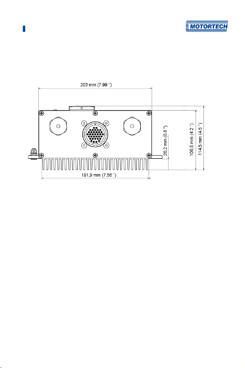
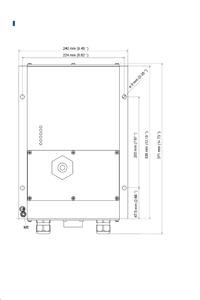
360.3 mm x 240 mm x 114.5 mm (14.19" x 9.45" x 4.51")
(length x width x height)
MIC5-SE:
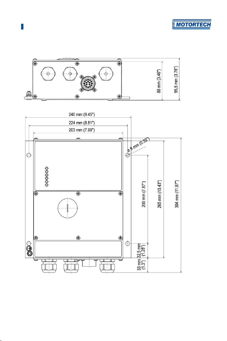
304 mm x 240 mm x 95.5 mm (11.97" x 9.45" x 3.76")
(length x width x height)
Weight MIC5:
8.2 kg (18.1 lbs)
MIC5-SE:
3.9 kg (8.5 lbs)
Shape of device See chapter Overview Drawings on page 27
Mechanical environmental
conditions
The housing is resistant to general atmospheric
contaminations.
Resistant to gas engine lubricants.
MIC5:
Protection class: I
Protection: IP65
MIC5-SE:
Protection class: I
Protection: IP54
The specified protection classes and types are only
guaranteed if all external wiring connections are made in
accordance with the connector specification, all covers and
seals are installed as intended and the following tightening
torques are observed:
– All M4 bolts: 0.8 Nm to 1 Nm (0.6 lb-ft to 0.7 lb-ft)
– PG screw joints: 4.5 Nm to 5 Nm (3.3 lb-ft to 3.6 lb-ft)
– Service screw: 2.5 Nm to 3 Nm (1.9 lb-ft to 2.2 lb-ft)
Always use a new seal when installing the service cover.
Standard single seal inserts
for PG screw joints
Rev. 03/2019 19
Suitable for a cable with a diameter of 6 mm to 13 mm.
Page 20

4 Product Description
Feature Value
Multiple seal inserts for PG
screw joints
Climatic environmental
conditions
4.1.3 Warning Notices on the Device
Validity of warning notices on device
The warning notices on the device are valid for the MIC5 and all components
connected to it.
Warning notice on the device German translation French translation
WARNING! Read and
understand the installation
and operating manual prior to
installing or making any
adjustments.
EXPLOSION HAZARD! Do not
disconnect while circuit is
live unless area is known to
be non-hazardous. For wiring
details refer to the operating
manual.
CAUTION! Do not pressure
wash this ignition module.
Damage to electronic
components may result.
Suitable for up to three cables, each with a diameter of
6 mm to 7 mm.
Housing surface temperature: –40 °C to +60 °C (–40 °F to
+140 °F)
Max. 85 % humidity without condensation up to 2,000 m
(6,562') above sea level
WARNUNG! Lesen und
verstehen Sie die
Installations- und
Betriebsanleitung vor der
Installation und bevor
ATTENTION! Avant d’installer
ou d’effectuer une
modification, lisez et
comprenez le manuel
d’utilisation et d’installation.
Einstellungen vorgenommen
werden.
EXPLOSIONSGEFAHR! Keine
Verbindungen lösen, solange
der Stromkreis aktiv ist,
außer das Umfeld wird als
nicht explosionsgefährdet
eingestuft. Hinweise zur
Verkabelung finden Sie in der
Betriebsanleitung
ACHTUNG! Die
Zündsteuerungseinheit nicht
mit Hochdruck reinigen. Es
könnte zu Schäden an den
elektronischen Bauteilen
RISQUE D‘EXPLOSION! Ne
débranchez pas lorsque le
circuit est sous tension sauf
si la zone est connue pour
être non dangereuse. Pour
plus de détails de câblage,
veuillez consulter le manuel
d´utilisation.
ATTENTION ! Ne pas laver
cette boîte de contrôle en
utilisant un jet sous pression.
Les composants électriques
peuvent être endommagés.
führen.
20 Rev. 03/2019
Page 21
4 Product Description
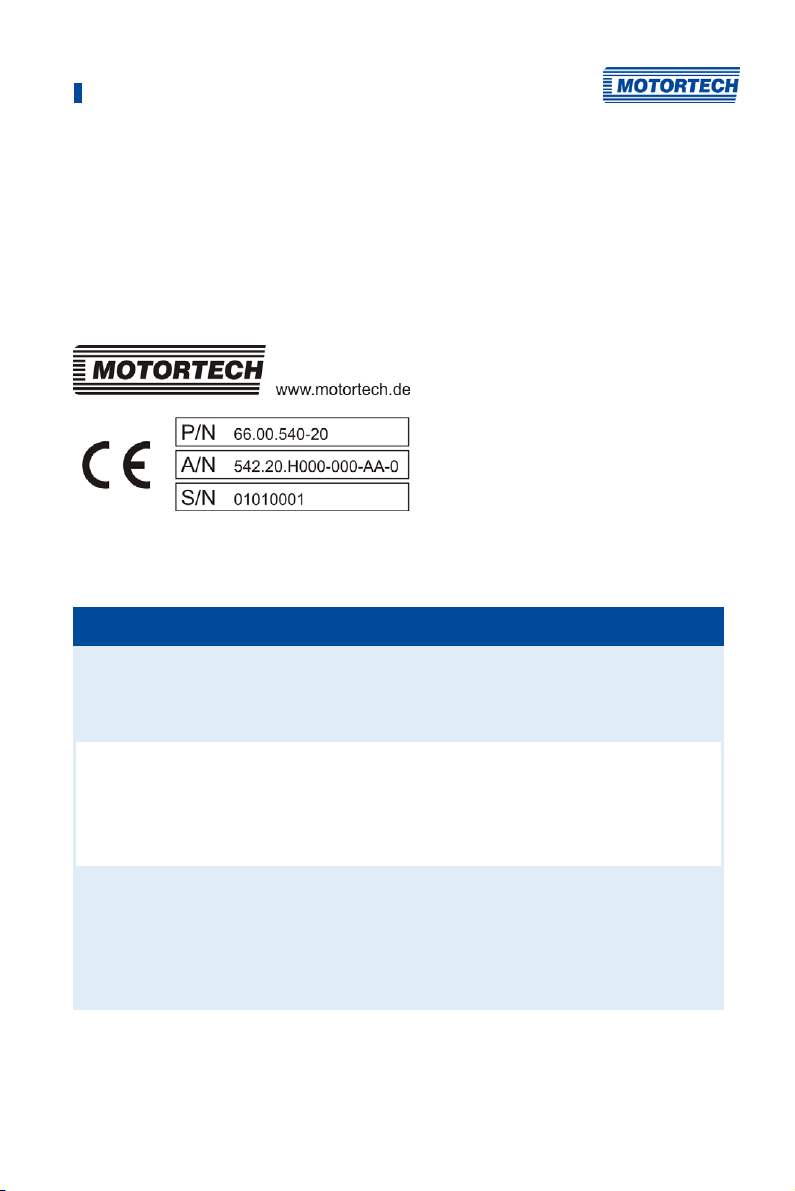
4.1.4 Product Identification – Labeling on the Device
The necessary numbers for unique product identification are on the device:
– Part number of the ignition controller (P/N)
– Arrangement number of the ignition controller (A/N)
– Serial number of the ignition controller (S/N)
Example MIC5
4.1.5 Electrical Data
The MIC5 has the following electrical characteristics.
Feature Value
Power consumption MIC5:
Power supply Nominal voltage: 24 V DC
Required current MIC5:
max. 240 W at 24 V
MIC5-SE:
max. 88 W at 24 V
MIC5:
Operating voltage: 16.8 V DC to 32 V DC
MIC5-SE:
Operating voltage: 10 V DC to 32 V DC
current max. 14 A.
MIC5-SE:
current max. 7 A.
An estimation of the power requirements can be found after this
table.
Rev. 03/2019 21
Page 22

4 Product Description
Feature Value
Number of outputs MIC5:
Firing Angles The size of the firing angle depends on the max. overspeed. The
Ignition frequency MIC5:
20 outputs
MIC5-SE:
8 outputs
smallest firing angle per output bank can be calculated using the
following formula:
With full energy output (all 20 ignition outputs with 500 mJ), an
ignition frequency of 300 Hz as continuous load is possible. With
less ignition energy or in case of a brief overload, 360 Hz is
possible. The maximum output load of 180 W must not be
exceeded.
MIC5-SE:
With full energy output (all 8 ignition outputs with 500 mJ), an
ignition frequency of 120 Hz as continuous load is possible. With
less ignition energy or in case of a brief overload, 150 Hz is
possible. The maximum output load of 75 W must not be
exceeded.
2-stroke engine:
4-stroke engine:
Output connector MIC5:
35-pole military connector
MIC5-SE:
17-pole military connector
22 Rev. 03/2019
Page 23

4 Product Description
Estimation of Current Requirements
These current values are based on a nominal speed of 1800 rpm and 500 mJ energy
MIC5:
Outputs Voltage Required current Voltage Required current
10 24 V 5 A 16 V* 7 A
16 24 V 7 A 16 V* 11 A
20 24 V 9 A 16 V* 14 A
* Nominal voltage 24 V DC
MIC5-SE:
Outputs Voltage Required current
8 24 V 4 A
Electrical Data for Inputs and Outputs
The inputs and outputs of the ignition controller have the following electrical data:
Inputs and outputs Values
Analog current input Current range: 0 mA to 20 mA (adjustable in MICT)
Input impedance: 27 || 1 µF
Analog voltage input Voltage range: 0 mA to 10 mA (adjustable in MICT)
Input impedance: 12.4 k || 200 nF
Auxiliary analog input
supply voltage
Binary input (Start/Stop) Wiring
Binary input (schedule A/B) Wiring
5 V to 24 V/50 mA depending on the configuration in the MICT
Input current: max. 20 mA
Ignition stop: 0 V to 0.8 V (low level)
Ignition release: 2.8 V to 32 V (high level)
Input current: max. 20 mA
Schedule A: 0 V to 0.8 V (low level)
Schedule B: 2.8 V to 32 V (high level)
Rev. 03/2019 23
Page 24

4 Product Description
Inputs and outputs Values
Binary input (GPI, general
purpose input)
Go/NoGo and GPO outputs One GPO (General Purpose Output) and one Go/NoGo output
Signal LED Six LEDs are used as status indicators.
ASO output TTL level (5 V)
Pickup input Impedance: 10 k
Ignition coil outputs Output voltage: max. 250 V
Wiring
Input current: max. 20 mA
Low level: 0 V to 0.8 V
High level: 2.8 V to 32 V
(Function dependent on the configuration in MICT, see
Inputs/Outputs – Inputs on page 110)
Implementation as optical MOSFET relay
Maximum switching voltage: 32 V DC
Peak/steady current: max. 100 mA DC
Output power: max. 2.5 W
Internal resistance: 58 Ω to 60 Ω
Activation delay: 0.5 ms / max. 100 mA load
Deactivation delay: 0.2 ms / max. 100 mA load
If a short is found at the output, a safety circuit, which makes
the output highly resistive, is found at the output, so that the
current sets itself at 50 mA to 60 mA.
max. current: ± 10 mA
The voltage supply for active pickup can be set using the
MICT from 5 V to 24 V.
Max. frequency for the pickups: 10 kHz
The formula for determining the frequency of the pickups can
be found in the note following this table.
For a pickup output impedance of 120 to 10 k, the pickups
connected to the MIC5 may not have a higher voltage than
±40 V and the connected power may not exceed 1 W.
Output energy in normal operation: max. 500 mJ (depending
on the ignition coils used)
Output energy in the start-up phase: max. 630 mJ (MIC5),
max. 600 mJ (MIC5-SE)
24 Rev. 03/2019
Page 25

4 Product Description
Frequency of the pickups
The frequency of the pickup is calculated as per the following formula.
4.1.6 Interfaces
Depending on the device version, the following interfaces are available:
USB Interface
– Compatible with USB 2.0
– The Connector B version is only suitable for temporary data exchange and not for a
permanent connection.
– Max. wire length 5 m (16.4')
CAN Bus Interface
– Classical Extended Frame Format (CAN 2.0B)
– As per ISO 11898 standard, 50 kbit/s to 1 Mbit/s
– Transient-proof (automotive classification)
– Max. 110 participants
– Max. wire length 250 m (820') depending on the transfer rate
RS485 Interface
– According to TIA-485-A (03/2003)
– Max. 32 participants
– Max. data transfer rate 9.6 kbit/s to 115.2 kbit/s
– Max. wire length 100 m (328') depending on the transfer rate
Pay attention to the wiring diagrams
Depending on the device version, certain signals or interfaces described in
these instructions may not be available. You are also always to pay
attention to the wiring diagrams enclosed with the input and output cable
harnesses.
Rev. 03/2019 25
Page 26

4 Product Description
4.1.7 Requirements for External Equipment
External equipment shall fulfill the input and output specifications of the MIC5.
26 Rev. 03/2019
Page 27
4 Product Description
4.1.8 Overview Drawings
Standard Version of MIC5 with Service Cover
Devices without a service cover have an input connector at the front of the device.
Rev. 03/2019 27
Page 28
4 Product Description
28 Rev. 03/2019
Page 29
4 Product Description
MIC5-SE
Rev. 03/2019 29
Page 30

4 Product Description
4.1.9 LEDs and Connections
LEDs on the MIC5
Labeling Function
Status LED flashes green when the device is running with no errors. If an error
occurs, the LED is red, for a warning it is yellow.
Firing LED lights up when the ignition is active (exception: during the self test).
Pickup 1 to 3 Flashing LEDs indicate activity of the pickups.
GPO LED is on when the GPO is activated.
Connections and Functions under the Service Cover
30 Rev. 03/2019
Page 31
4 Product Description
Labeling Function
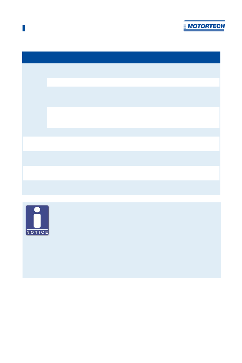
Connections and
functions under the
service screw
Pickup Connection for the pickups (see Input Wiring – Pickups on page 41)
CAN CAN interface for connecting external equipment (see Output
Binary Output Connection for binary outputs (refer to Output Wiring – Binary
RS485 RS485 interface for connecting external equipment (see Output
Analog/Binary Input Connection for timing & safety devices (see Input Wiring – Timing
Power Connection for the supply voltage (see Input Wiring – Power Supply
USB USB connection for connecting to the PC
PB Button acknowledges errors, warnings and alarms or triggers a
A/B Potentiometer for the manual adjustment of the ignition timing.
on page 39)
reset of the ignition controller. Please refer also to the notice
below.
The setting only has an effect if the potentiometer in the MICT is
activated.
Wiring – CAN Bus Interface on page 49)
Outputs (Go/NoGo, GPO, ASO) on page 46)
Wiring – RS485 Interface on page 51)
and Safety Devices on page 43)
Behavior of the button PB
With the PB button on the device you can perform the following actions:
– Press briefly (< 3 s):
Existing warnings are acknowledged.
– Press longer than 3 s:
If no pickup signals are detected and an operating error exists, this will
be acknowledged together with all alarms. Warnings are acknowledged
in any case, even if no operating error exists.
– Press longer than 15 s:
If no pickup signals are detected, the ignition controller restarts.
Rev. 03/2019 31
Page 32

5 Installation Instructions
5.1 Unpacking
Unpack the equipment, taking care not to damage it. Always place the device safely and
protected from falling over or falling down. Ensure that the operating manual is always stored
with the ignition controller and is easily accessible. Check the contents for completeness and
verify that the device type meets your application requirements.
Scope of Supply
The scope of supply of the MIC5 ignition controller consists of the following components:
– Ignition controller of the MIC5 series
– Installation set incl. four vibration dampers
– Ground strap
– Three multiple sealing inserts and five sealing plugs for PG screw joints
– Storage device (USB flash drive or CD-ROM) with software for configuring the ignition
controller
– USB interface cable for connecting the ignition controller to a PC/laptop
– Operating manual
5.2 Installation of the Ignition Controller
The installation of the MIC5 ignition controller is implemented on a fixed bracket e. g. on a wall
near the engine. Use the included rubber vibration dampers and the ground strap. The
installation location of the controller must be selected so that the distance to the pickups
installed on the engine ensures a reliable signal transmission to the ignition controller, and so
that there is adequate space for maintenance and repair work. The mechanical specifications
must always be complied with (refer to Mechanical Data on page 19). The ground strap serves to
ground the ignition controller and must be used accordingly. Ensure a flawless electrical
connection for this purpose.
Installation locations where strong vibrations or extreme ambient temperatures are present are
not permissible and result in the warranty being voided. The permitted temperature range is
–40 °C (–40 °F) to +60 °C (+140 °F). To ensure sufficient cooling through the cooling body, the
device must be mounted so that the vanes of the cooling body are vertical and the hot air can
escape upwards unimpeded.
Risk of destruction!
The device must not be installed directly on or at the engine, as vibration
and heat may cause damage to electronic components. This also applies if
vibration dampers are used.
32 Rev. 03/2019
Page 33
5 Installation Instructions
A
5.2.1 Installation of the Vibration Dampers
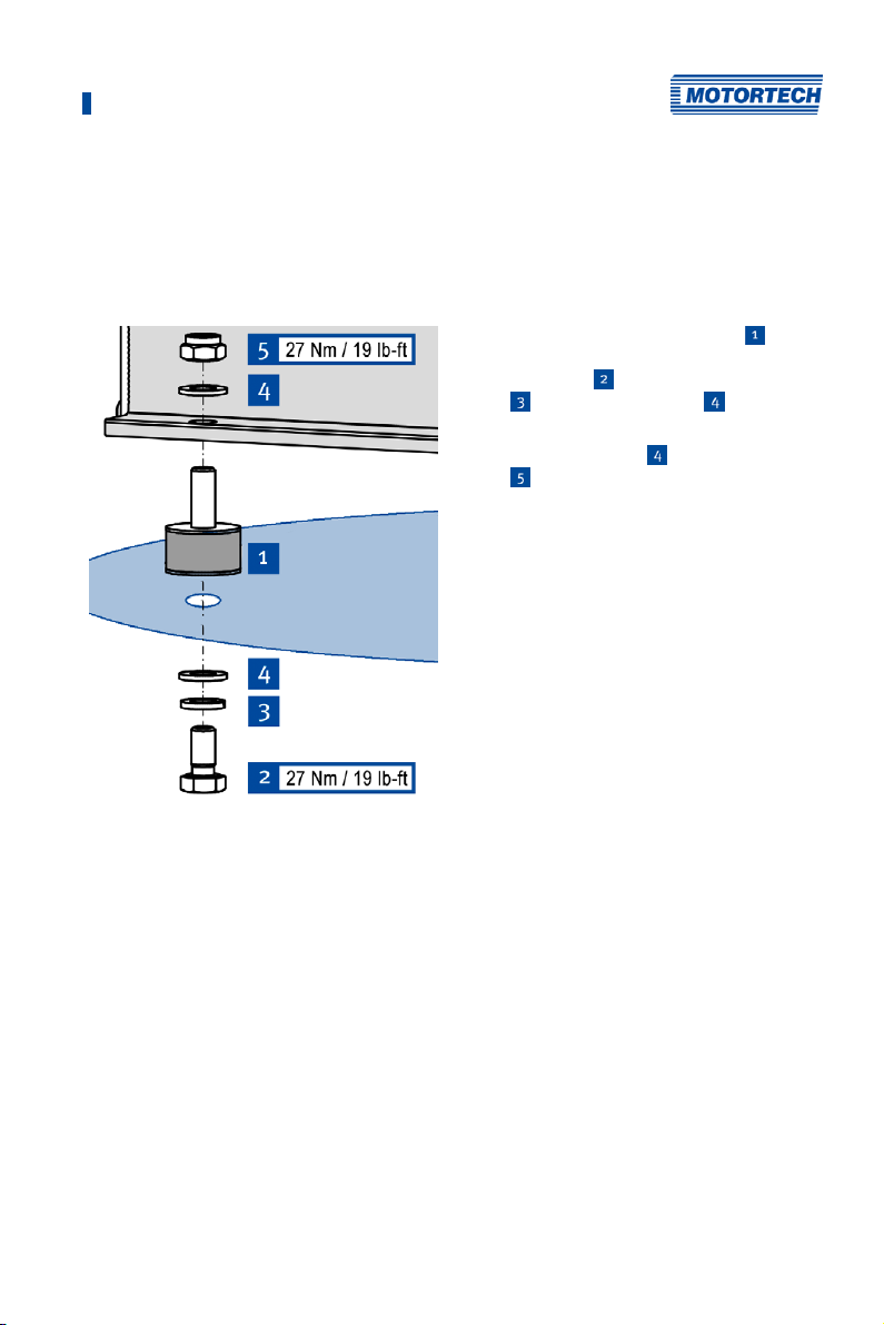
There are two options for using the vibration dampers from the MIC5's scope of supply. The hole
patterns can be found in section Overview Drawings on page 27.
Option
1. Fasten the four vibration dampers
selected installation location. Use four
screws M8x16
M8
and four washers M8 .
2. Fasten the MIC5 to the vibration dampers.
Use four washers M8
M8
.
Fasten the ground strap to the ground
pin (see Installation of the Ground
Strap on page 34).
, four rim lock washers
and four lock nuts
to the
Rev. 03/2019 33
Page 34
5 Installation Instructions
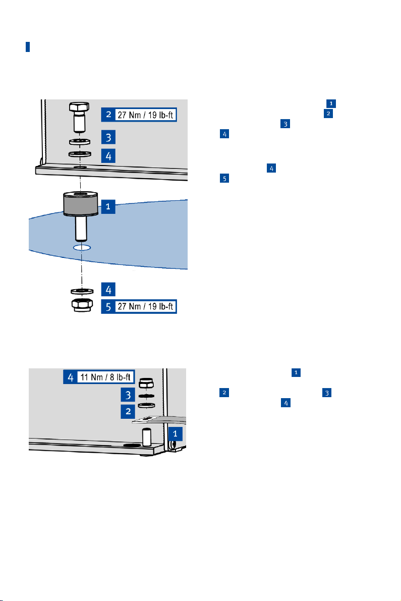
Option B
1. Fasten the four vibration dampers
the MIC5. Use four screws M8x16
rim lock washers M8
M8
.
2. Fasten the MIC5 to the selected installation
location using the vibration dampers. Use
four washers M8
M8
.
Fasten the ground strap to the ground
pin (see Installation of the Ground
Strap on page 34).
and four washers
and four lock nuts
to
, four
5.2.2 Installation of the Ground Strap
1. Fasten the ground strap
ground pin. To do so, use one washer
M6
, one tooth lock washer A6 and
one poly lock nut M6
2. Connect the ground strap to one of the
sides suitable for grounding.
You can wire the ignition controller as
described in section Wiring of the
34 Rev. 03/2019
Device on page 36.
to the MIC5
.
Page 35

5 Installation Instructions
5.3 Determine the Installation Location of the Pickup
Set the positions of the pickups depending on engine type and application. All angle reference
information is based on:
TDC 1st cylinder / compression cycle
The installation location for the pickups must have adequate mechanical strength and must not
exceed the specified temperature ranges. The pickups are designed for the appropriate use
only, multiple use of the pickup signal is not permissible. Ensure good accessibility to facilitate
the calibration of the sensor. Comply with the pertinent regulations for the wire routing.
For the exact positioning of the individual pickups, refer to the examples given in the drawings
(see section Input Wiring – Pickups on page 41).
Rev. 03/2019 35
Page 36
6 Wiring of the Device
6.1 Input and Output Wiring on the Controller
Operational safety!
All connector screws and screw joints must be adequately tightened. Refer
to the section Mechanical Data on page 19.
After the service cover on the device has been opened, e.g. to complete the
wiring, it must be refitted so that it is in the same alignment as it was prior
to opening. The USB connection must always be below the service screw. If
the mounting is rotated, maintaining the indicated protection classes, as
well as compliance with CSA-Class I, Division 2 (Group C, D) is impaired.
Operational safety!
Improper wiring using the PG screw joints impairs the compliance with the
specified protection classes as well as with CSA Class I, Division 2 (Group C,
D). Please adhere to the following points:
– Do not pass any cables without matching sealing inserts through the PG
screw joints.
– A sealing insert must be used in every PG screw joint.
– Unused bore holes for the sealing inserts must be sealed using sealing
plugs.
– The PG screw joints must be adequately tightened.
For additional information on PG screw joints and sealing inserts please
refer to Mechanical Data on page 19.
Assignment of the wire colors
Take the assignment of the wire colors of the wiring harness for the input
and output wiring from the wiring diagram enclosed with the wiring
harness.
Pay attention to the wiring diagrams
Depending on the device version, certain signals or interfaces described in
these instructions may not be available. You are also always to pay
attention to the wiring diagrams enclosed with the input and output cable
harnesses.
36 Rev. 03/2019
Page 37
6 Wiring of the Device
6.1.1 Input Wiring
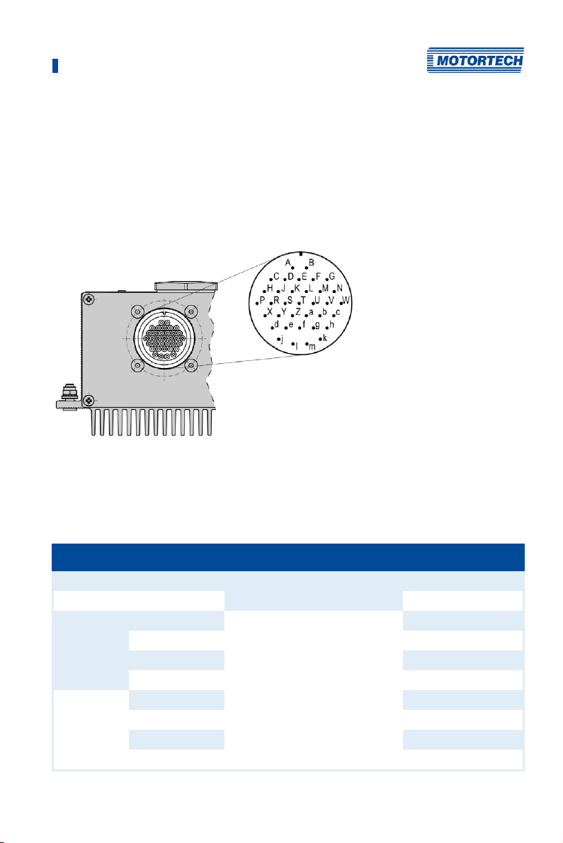
For the standard MIC5 version, the connections for the input wiring are located on the connector
strip below the service cover (see LEDs and Connections on page 30). The wiring to the connector
strips is fed through the PG screw joints at the device front.
For device versions without a service cover, the input wiring is established using a 35-pole input
connector at the device front.
35-Pole Input Connector
35-pole input connector (outside view)
Assignment of the Connections
The table contains the connection assignment of different MIC5 versions. The wiring examples
contained in this operating manual refer to devices with a service cover and connector strip.
Pin designation Connection no. on connector strip 35-pole connector
L – (negative pole) Power 1 B
L + (24 V) 2 A
Pickup 1 Power Pickup 1 C
Signal 2 D
GND 3 E
Shield 4 F
Pickup 2 Power 5 G
Signal 6 H
GND 7 J
Shield 8 K
Rev. 03/2019 37
Page 38

6 Wiring of the Device
f
Pin designation Connection no. on connector strip 35-pole connector
Pickup 3 Power 9 –
Signal 10 –
GND 11 –
Shield 12 –
CAN Display Hi CAN 1 –
Com 2 –
Lo 3 –
Shield 4 –
CAN Hi 5 L
Com 6 M
Lo 7 N
Shield 8 P
Go/NoGo + Binary
Go/NoGo – 2 S
GPO + 3 T
GPO – 4 U
ASO + 5 V
ASO – 6 W
ASO Shield 7 X
Timing U in + Analog/
Analog GND 2 d
Analog PWR 3 e
Timing I in – 4
Timing I in+ 5 g
Analog Shield 6 h
Start/Stop + 7 j
Schedule A/B + 8 k
GPI1 + 9 l
Binary Com 10 m
Binary Shield 11 –
Output
Binary
Input
1 R
1 –
38 Rev. 03/2019
Page 39

6 Wiring of the Device
Y
Pin designation Connection no. on connector strip 35-pole connector
RS485 TX + RS485 1
TX – 2 Z
Com 3 a
RX + 4 b
RX – 5 c
Shield 6 –
6.1.2 Input Wiring – Power Supply
Operational safety
The correct operation of the device is only guaranteed if the device is
operated within the permissible supply voltage range. Therefore, use a
power supply according to the specifications in the operating instructions.
Design of power supply
For the power supply, an overcurrent protection mechanism must be set up
with a circuit breaker (MIC5: 20 A DC, MIC5-SE: 16 A DC can both be set with
tripping characteristic B), which allows switching off. When selecting the
circuit breaker, the conditions of the installation site and the ambient
temperature must be considered. The circuit breaker must be easy for the
user to access and marked as a disconnecting device for the ignition
controller.
If the power is supplied via a power supply unit, the following specifications
must be observed additionally:
MIC5:
– Voltage: 24 V DC; Current: at least 30 A
– Wiring: at least 2.5 mm² cross-section
MIC5-SE:
– Voltage: 24 V DC; Current: at least 25 A
– Wiring: at least 1.5 mm² cross-section
Rev. 03/2019 39
Page 40
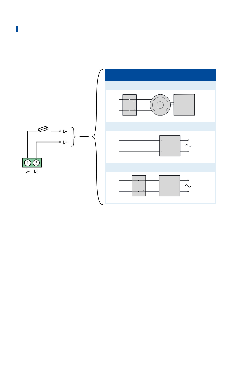
6 Wiring of the Device
L ≙ 24 V DC (nominal voltage)
Variations
1 Battery Generator Control unit
2 Power supply
3 Battery Charger
40 Rev. 03/2019
Page 41
6 Wiring of the Device
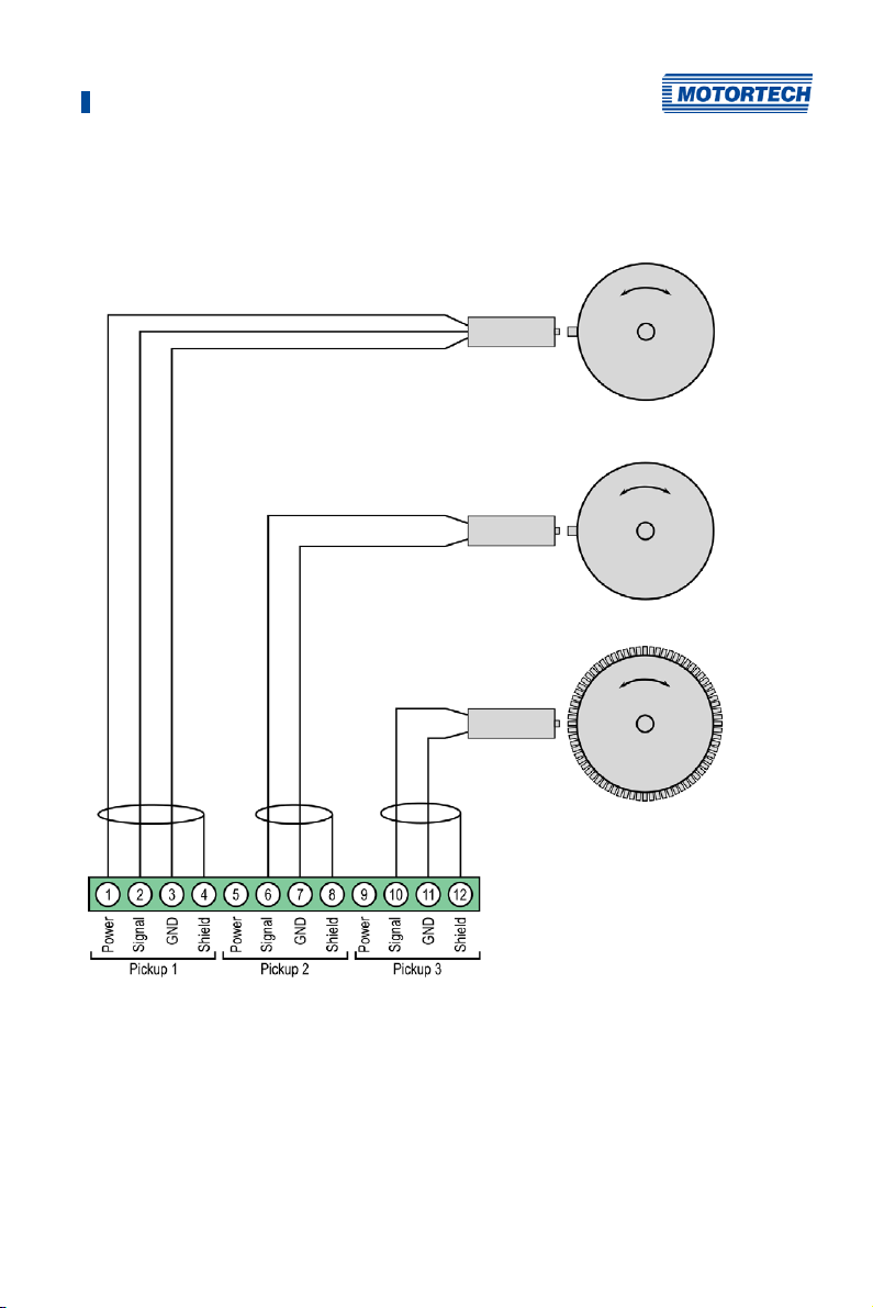
6.1.3 Input Wiring – Pickups
Example Configuration (one Active, two Passive Pickups)
Camshaft
Crankshaft
(Reset)
Crankshaft
The recommended distance to the triggering is 0.75 mm to 1 mm (0.03" to 0.04") for MOTORTECH
pickups. Please note that additional fine-tuning is required for every pickup position due to the
different conditions of the engines.
Rev. 03/2019 41
Page 42

6 Wiring of the Device
One revolution of the pickup changes the distance as follows:
Thread Change in distance
M12x1 1 revolution ≙ 1 mm (0.04'')
5/8"-18 UNF 1 revolution ≙ 1.41 mm (0.05")
3/4"-16 UNF 1 revolution ≙ 1.59 mm (0.06")
Allocation of the Wire Colors (Example Configuration)
Camshaft
PIN Designation Wire color
1 Pickup 1 Power Brown
2 Pickup 1 Signal black
3 Pickup 1 GND blue
4 Pickup 1 Shield Shield
Crankshaft (Reset)
PIN Designation Wire color
6 Pickup 2 Signal Flywheel with pin
White
7 Pickup 2 GND Flywheel with pin
Brown
8 Pickup 2 Shield Shield
Crankshaft
Flywheel with hole
Brown
Flywheel with hole
White
PIN Designation Wire color
10 Pickup 3 Signal White
11 Pickup 3 GND Brown
12 Pickup 3 Shield Shield
For problems with the pickup signals, refer to the section Pickup Input Errors on page 164.
42 Rev. 03/2019
Page 43
6 Wiring of the Device
Adjusting the pickup sensitivity
Depending on the type of impulse source (interference), it may be necessary
to increase the pickup sensitivity to ensure that the resultant signal
strength is sufficient for reliable operation. You can make these
adjustments in the MICT. Refer to the section Engine – Pickups on page 96.
Aux. pickup supply voltage
An auxiliary supply voltage for active pickups can be configured using the
MICT. The voltage can be set in the range from 5 V to 24 V and is supplied at
the connections Pickup 1 Power to Pickup 3 Power. Refer to the section
Engine – Pickups on page 96.
6.1.4 Input Wiring – Timing and Safety Devices
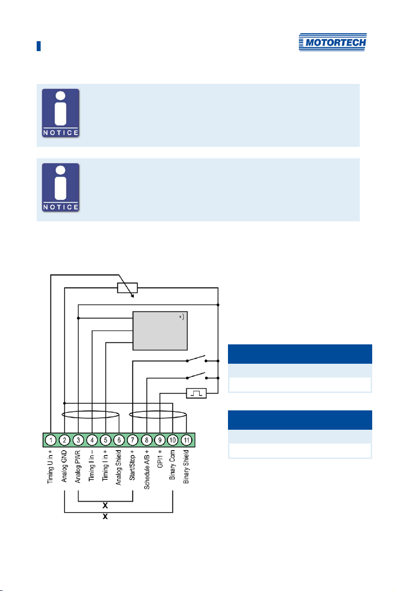
Example Configuration
)
See subsequent drawings for details
*
x = bridge for permanent authorization
(must be removed for external ignition
authorization)
Switch Start/Stop
open Ignition – OFF
closed Ignition – ON
Switch A/B
open Schedule A
closed Schedule B
Rev. 03/2019 43
Page 44
6 Wiring of the Device
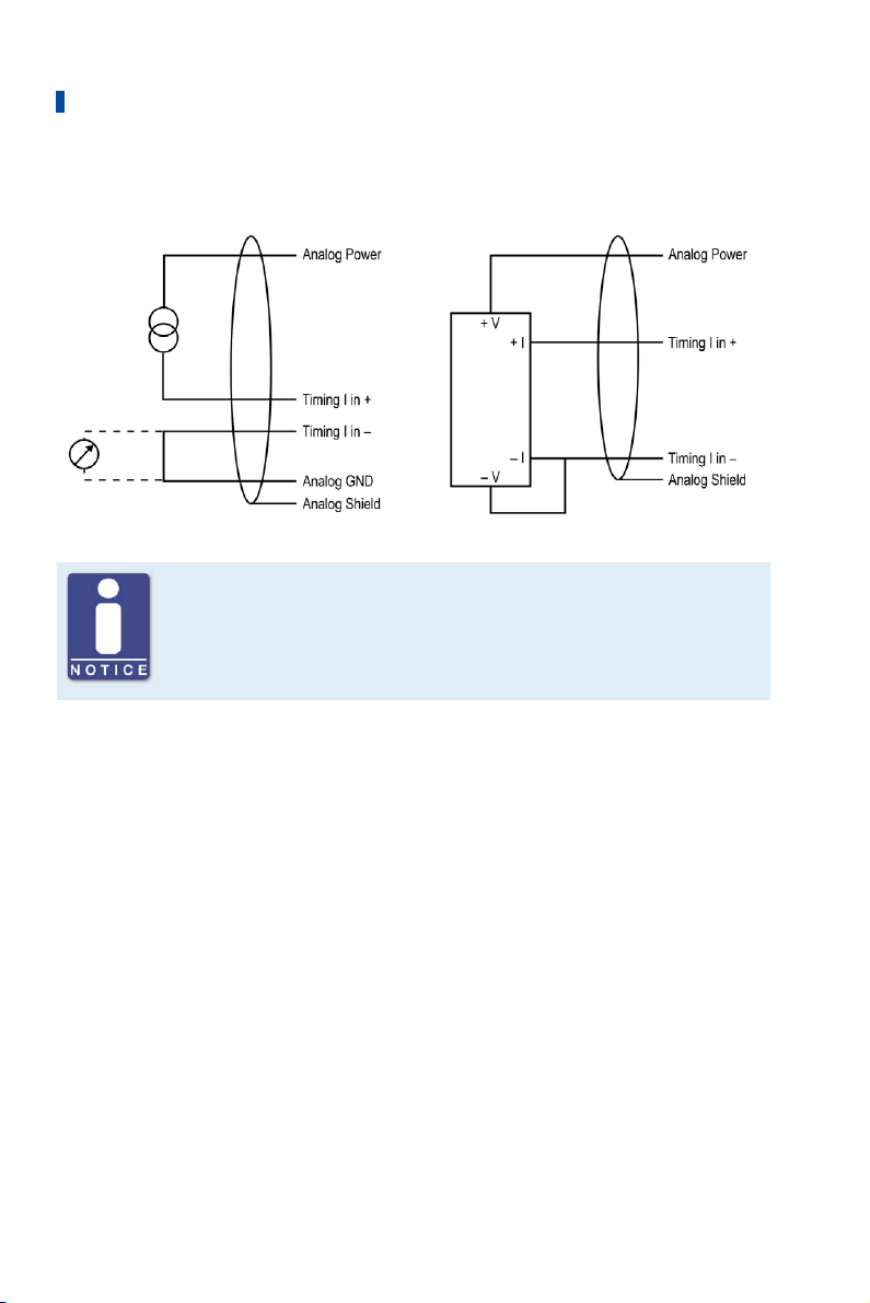
Two-Wire Transmitter
Auxiliary analog input supply voltage
An auxiliary supply voltage for the analog inputs can be configured using
the MICT. The voltage can be set in the range of 5 to 24 V and is made
available on the connection Analog Power. Please refer to the section
Timing – Analog Inputs on page 100.
Four-Wire Transmitter
44 Rev. 03/2019
Page 45
6 Wiring of the Device
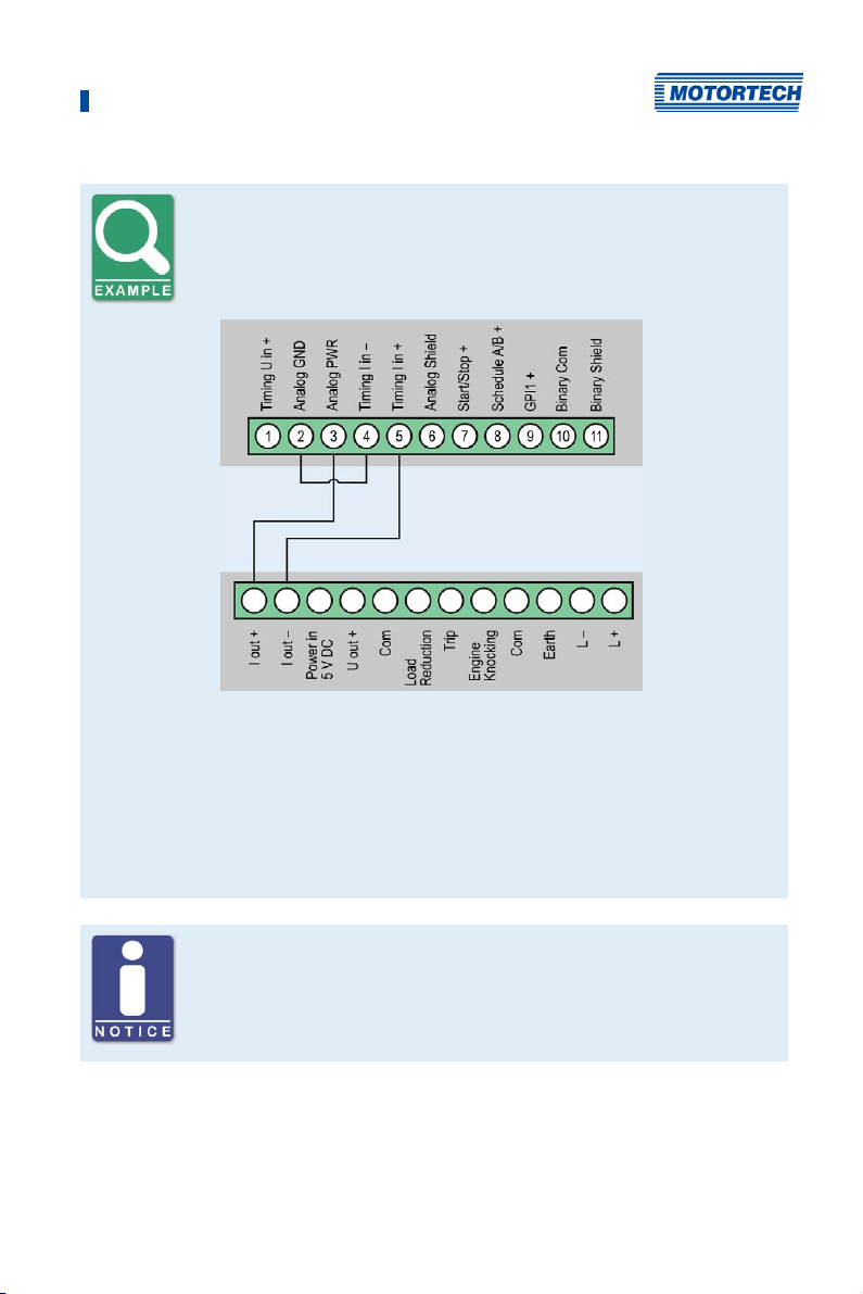
Wiring MIC5 ignition controller and DetCon detonation control system
The following diagram shows an example of the wiring of a MIC5 ignition
controller with a DetCon detonation control system in cases where the
analog current signal (4-20 mA) at the output I out is to be used for the
ignition timing adjustment.
Furthermore, the limits of the analog current input will need to be set at
4 mA to 20 mA and the auxiliary supply voltage of the analog inputs to 24 V
in the MICT. Please refer to the section Timing – Analog Inputs on page 100.
The timing is transmitted by MIC5 via the auxiliary synchronization output
(ASO) to the DetCon, and will need to be wired and configured accordingly.
Please refer to the section Output Wiring – Binary Outputs (Go/NoGo, GPO,
ASO) on page 46.
General purpose input GPI
The general purpose input GPI can be assigned various functions via the
configuration. Refer to the section Inputs/Outputs – Inputs on page 110.
MIC5
ignition
controller
DetCon
detonation
control system
Rev. 03/2019 45
Page 46
6 Wiring of the Device
6.1.5 Output Wiring – Binary Outputs (Go/NoGo, GPO, ASO)
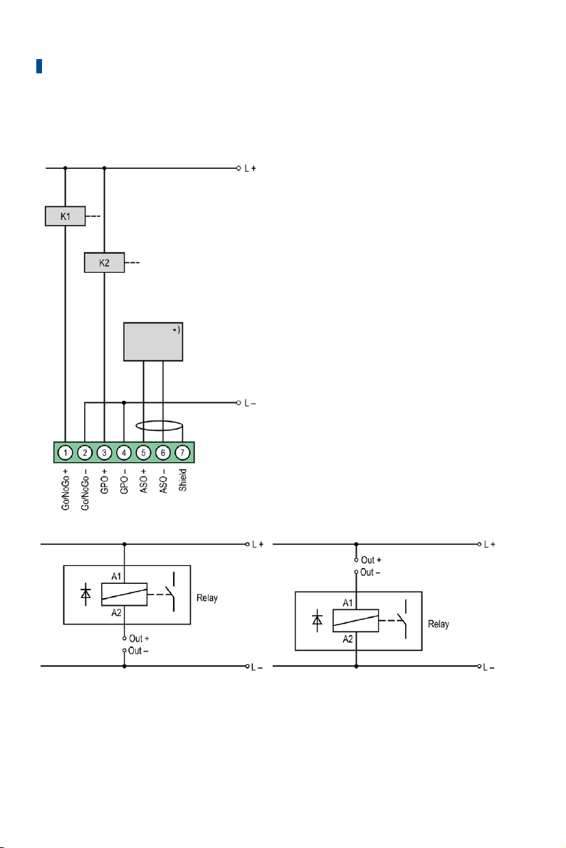
Example Configuration
*) DetCon or other external device (for wiring
of the DetCon, see following example)
K1 = Go/NoGo relay
K2 = GPO relay
L ≙ 7 V DC to 32 V DC
(L ≙ 7 V DC to 32 V DC)
46 Rev. 03/2019
Page 47
6 Wiring of the Device
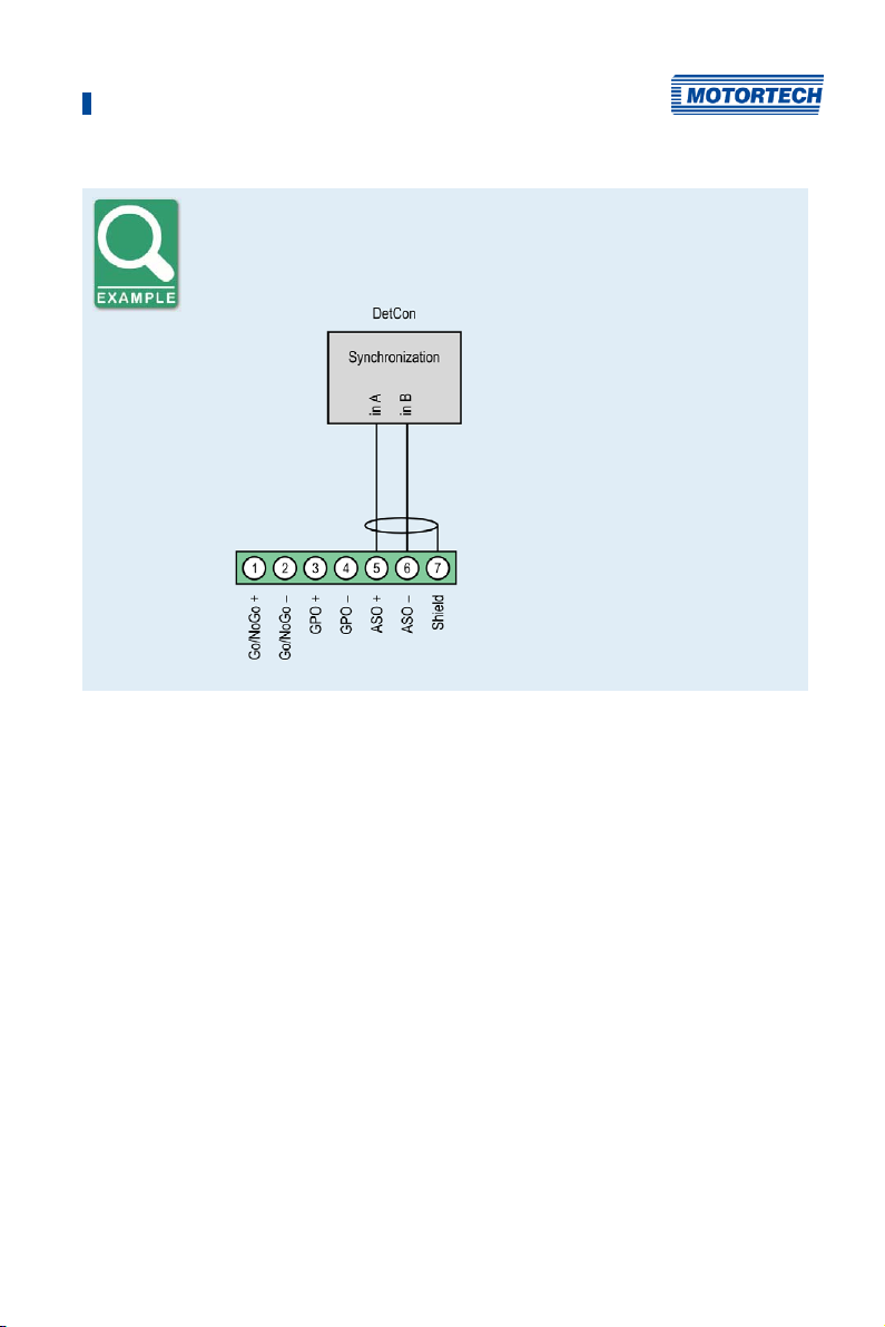
DetCon connection
Connect the ASO output on the DetCon to the connections in A and in B on
connector Synchronization.
6.1.6 Wiring – PowerView3
Connect the PowerView3 visualization unit to the MIC5 as follows.
CAN Connection between Ignition Controller and PowerView3
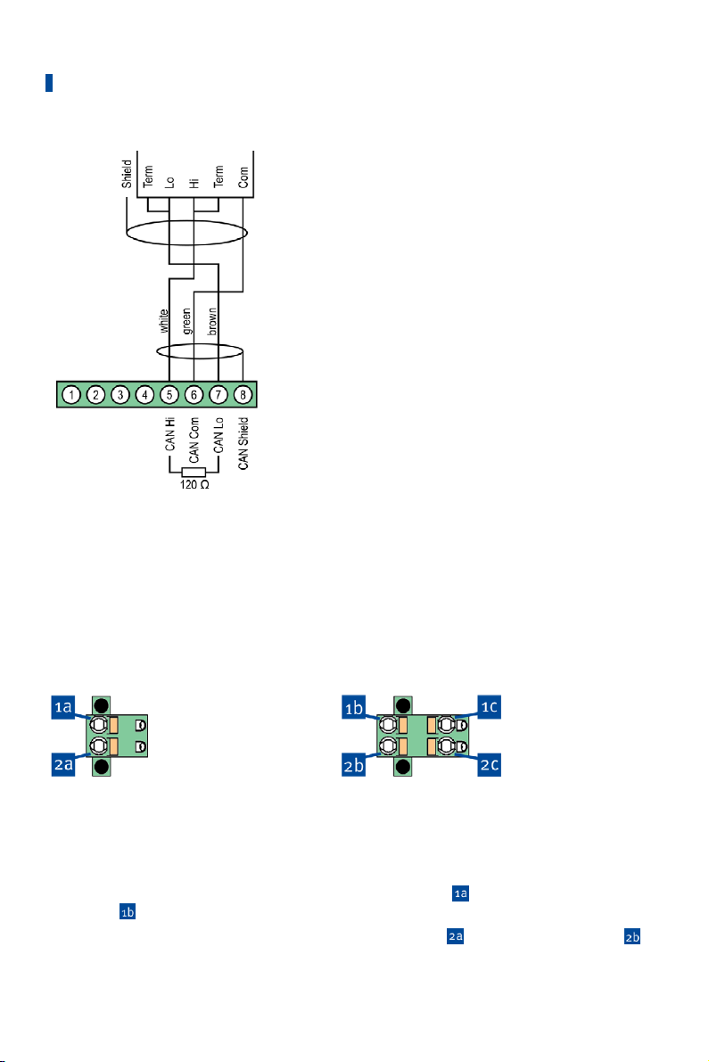
As shown in the following illustration, you can connect the PowerView3 directly to the
MOTORTECH ignition controller using the CAN cable delivered with the PowerView3. To do so,
you need to insert the connector in the CAN interface on the PowerView3. On the ignition
controller, connect the color-coded conductors of the CAN cable to the correct CAN interface
connections.
Rev. 03/2019 47
Page 48
6 Wiring of the Device
Connector for CAN
interface on PowerView3
CAN interface on the
ignition controller
PowerView3 Power Supply via the Ignition Controller
If you use a MOTORTECH ignition controller with a service cover and connector strip, you have
the option of supplying power to the PowerView3 via the ignition controller. A special connector
is included in the PowerView3's scope of supply. The connector for the voltage supply of the
ignition controller must be replaced by this one.
Connector supplied with
the ignition controller:
Connector supplied with
PowerView3:
Proceed as follows:
1. Disconnect the power supply to the ignition controller and, if necessary, to the PowerView3.
2. Remove the connector for the power supply from the ignition controller.
3. Negative terminal: Disconnect the conductor from the contact
contact
4. Positive terminal: Disconnect the conductor from the contact
of the connector provided with the PowerView3.
48 Rev. 03/2019
of the connector provided with the PowerView3.
and insert it into
and insert it into contact
Page 49
6 Wiring of the Device
5. From the PowerView3 power supply cable, plug the L– wire (white) into contact . For
plugging into the contact, use a wire end ferrule provided with the PowerView3.
6. From the PowerView3 power supply cable, plug the L+ wire (brown) into contact
plugging into the contact, use a wire end ferrule provided with the PowerView3.
7. Insert the connector provided with the PowerView3 into the power supply connection of the
ignition controller.
8. Insert the connector at the other end of the PowerView3 power supply cable into the
PowerView3 power supply connection.
9. Connect the device's power supply.
The power supply of the PowerView3 is now provided through the connector on the
ignition controller.
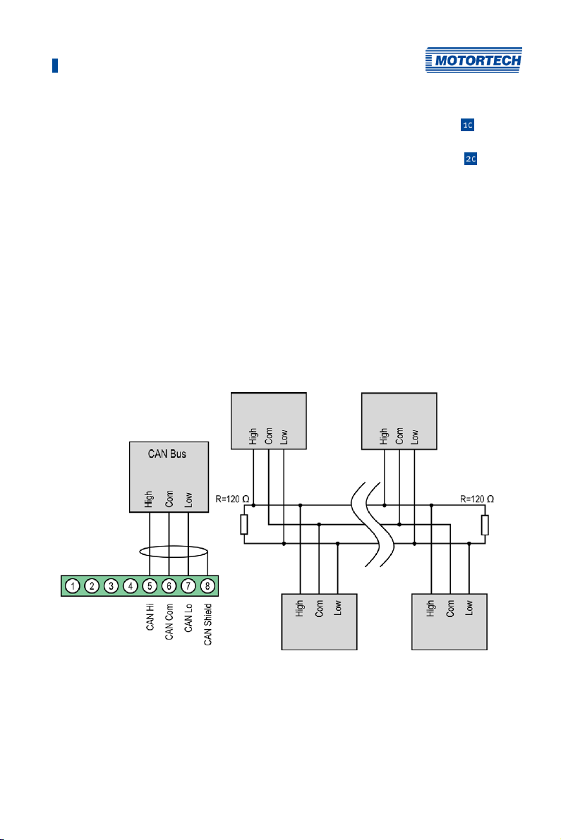
6.1.7 Output Wiring – CAN Bus Interface
The product must be connected to a CAN bus as follows:
First device Second-to-last device
. For
Notice: The CAN-Bus connectors 1-4 are currently unavailable.
Rev. 03/2019 49
Second device Last device
Page 50

6 Wiring of the Device
CANopen® protocol
If you require information on the CANopen® protocol, contact your
MOTORTECH contact person.
CAN bus wiring
Note the following when connecting the CAN bus:
– Each bus end must be fitted with a terminating resistor of 120 Ω (see
drawing).
– The maximum wire length depends on the bit rate:
Bit rate Maximum wire
length
Maximum length
of a stub
Maximum length of
all stubs
1 Mbit/s 25 m (82') 1.5 m (5') 7.5 m (25')
800 kbit/s 50 m (164') 2.5 m (8') 12.5 m (41')
500 kbit/s 100 m (328') 5.5 m (18') 27.5 m (90')
250 kbit/s 250 m (820') 11 m (36') 55 m (180')
125 kbit/s 500 m (1,640') 22 m (72') 110 m (360')
50 kbit/s 1,000 m (3,280') 55 m (180') 275 m (902')
– Only use cables that are specified by the manufacturer for use in the
CAN bus.
50 Rev. 03/2019
Page 51
6 Wiring of the Device
6.1.8 Output Wiring – RS485 Interface
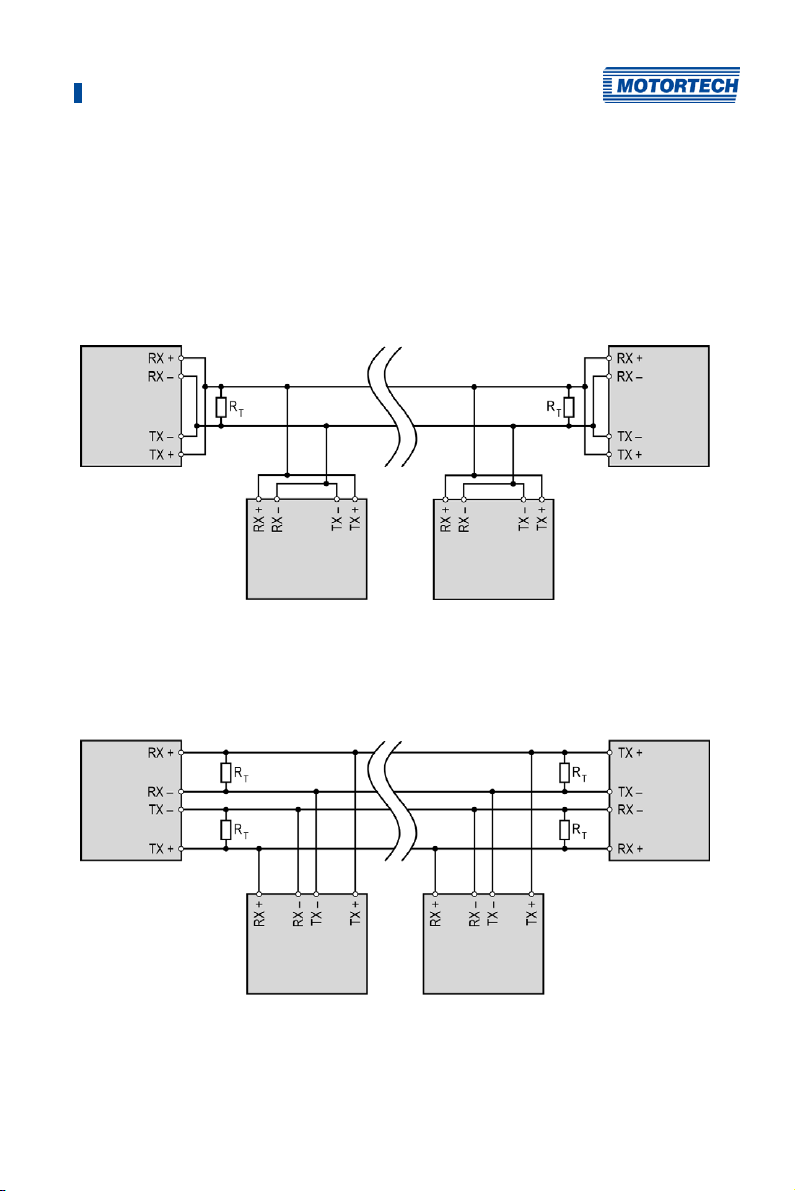
The RS485 interface can be wired as two-wire or four-wire wiring and twisted cables must be
used. With both variants the load resistance (R
cable.
Two-Wire Wiring
First device Last device
Second device Second-to-last device
Four-Wire Wiring
First device
(Master)
Last device
T=120 Ω) is the characteristic impedance of the
(Slave)
Second device
(Slave)
Rev. 03/2019 51
Second-to-last device
(Slave)
Page 52
6 Wiring of the Device
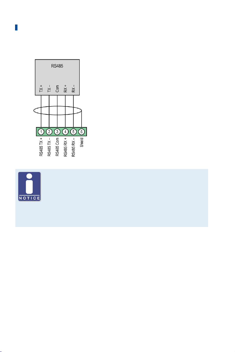
Connection on the Ignition Controller
Wiring of the RS485 interface
Follow these instructions for the RS485 interface wiring:
– Max. 32 devices can be connected to a bus.
– The maximum wire length is 100 m (328') depending on the transfer
rate.
– Each bus end must be fitted with a terminating resistor with 120 Ω in
each pair of leads (as indicated in the drawing).
52 Rev. 03/2019
Page 53

6 Wiring of the Device
6.2 Ignition Coil Wiring
Ignition coil wiring
In the MICT there are two types of wiring with predefined output
configuration supported in the engine database for many engines:
– Wired in straight order
– Wired in firing order
For information on straight order wiring refer to Straight Order Wiring of the
Ignition Outputs on page 56 and Engine – Parameters on page 88.
For wiring in firing order, the first cylinder in the firing order is connected to
the A1 output, the second to B1 (A2 for one output board), etc.
If a different wiring was implemented, the output configuration in the MICT
must be adapted accordingly. Please note that the wiring cannot be
checked by the software (see section Engine – Parameters on page 88).
Conductor cross-section for primary wiring
If you do not use a harness manufactured by MOTORTECH, the primary
wiring must have a conductor cross-section of 1.5 mm².
Rev. 03/2019 53
Page 54
6 Wiring of the Device
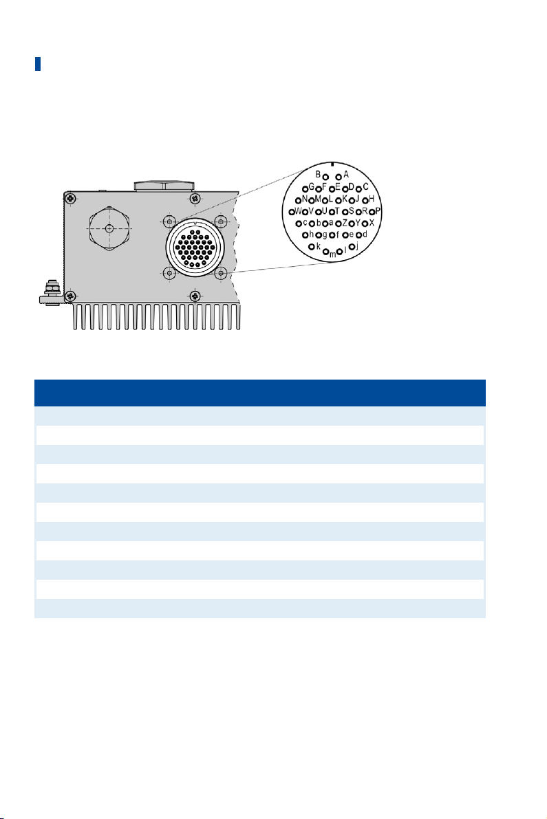
6.2.1 Ignition Coil Wiring for a 35-Pole Connector
The table shows the pole assignments for the output connector.
35-pole output connector (outside view)
Pole Output Pole Output
A Output A1 L Output A6
B Output B1 M Output B6
C Output A2 N Output A7
D Output B2 P Output B7
E Output A3 R Output A8
F Output B3 S Output B8
G Output A4 T Output A9
H Output B4 U Output B9
J Output A5 V Output A10
K Output B5 W Output B10
m Ground
54 Rev. 03/2019
Page 55
6 Wiring of the Device
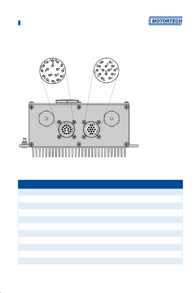
6.2.2 Ignition Coil Wiring 17-Pole and 14-Pole Connector
The table shows the pole assignments for the output connector.
17-pole output connector and 14-pole output connector (MIC5, outside view)
The MIC5-SE has only one 17-pole output connector.
Pole Output (17-pole) Pole Output (14-pole)
A Output A1 A Output B1
B Output A2 B Output B2
C Output A3 C Output B3
D Output A4 D Output B4
E Output A5 E Output B5
F Output A6 F Output B6
G Output A7 G Output B7
H Output A8 H Output B8
J Output A9 I Output B9
K Output A10 J Output B10
N Ground N Ground
Rev. 03/2019 55
Page 56

6 Wiring of the Device
6.2.3 Straight Order Wiring of the Ignition Outputs
Risk of damage to engine
If you use straight order wiring, it is absolutely necessary that the
MOTORTECH wiring rail for the respective engine is used and correctly
installed. Even a rotated installation can cause serious damage to the
engine, for example.
Straight order wiring, along with wiring in firing order, is supported by the MICT for many
engines with predefined output configurations in the engine database. That means that if the
wiring is carried out accordingly and the option Wired in Straight Order is selected in the MICT,
no other adaptation of the output configuration is necessary.
You can use straight order wiring, if:
– Wiring takes place via a corresponding MOTORTECH wiring harness and a MOTORTECH
wiring rail. The harness is marked with the following information: PLEASE NOTE! The firing
order needs to be configured directly in the ignition controller. The ignition coils on the
wiring rail are identified with Connector Pin 1 to Connector Pin X.
– Make the wiring of the ignition controller corresponding to the instructions in the following
sections (for example with an open wiring harness or via a junction box).
Execution of straight order wiring is dependent on the following factors:
– One or two output banks in the ignition controller
– The type of engine (in-line or V-engine)
– Alignment of the wiring rail(s)
56 Rev. 03/2019
Page 57

6 Wiring of the Device
6.2.4 Straight Order Wiring of the Ignition Outputs – Overview
MIC5
The following table contains the allocation of the MIC5 outputs to the cylinders.
Output In-line engine V-engine
Connector* Coil** Connector* Coil**
Output A1 1 1 1 1
Output B1 1 2 2 1
Output A2 1 3 1 2
Output B2 1 4 2 2
Output A3 1 5 1 3
Output B3 1 6 2 3
Output A4 1 7 1 4
Output B4 1 8 2 4
Output A5 1 9 1 5
Output B5 1 10 2 5
Output A6 1 11 1 6
Output B6 1 12 2 6
Output A7 1 13 1 7
Output B7 1 14 2 7
Output A8 1 15 1 8
Output B8 1 16 2 8
Output A9 1 17 1 9
Output B9 1 18 2 9
Output A10 1 19 1 10
Output B10 1 20 2 10
Ground
Connector* = connector on the wiring rail
Coil** = ignition coil with the corresponding number on the wiring rail
Rev. 03/2019 57
Page 58

6 Wiring of the Device
MIC5-SE
The following table contains the allocation of the MIC5-SE outputs to the cylinders.
Output In-line engine V-engine
Connector* Coil** Connector* Coil**
Output A1 1 1 1 1
Output A2 1 2 2 1
Output A3 1 3 1 2
Output A4 1 4 2 2
Output A5 1 5 1 3
Output A6 1 6 2 3
Output A7 1 7 1 4
Output A8 1 8 2 4
Ground
Connector* = connector on the wiring rail
Coil** = ignition coil with the corresponding number on the wiring rail
58 Rev. 03/2019
Page 59

7 Functions
The ignition controllers of the MIC5 series include freely configurable safety and auxiliary
functions that, amongst others, can shut down the engine in case of fault.
Angle indications in the operating manual
All angles in this operating manual are given in °crankshaft. Exceptions are
clearly identified.
7.1 Pickup Sensitivity
To increase the signal interference distance, the sensitivity of the pickup signal inputs can be
changed for suitable pickup signals. This setting can be implemented individually for each
input. For this purpose, a pre-trigger voltage can be set below which signals are interpreted as
interference and are therefore not analyzed. A pre-trigger voltage set to a high level will thus
result in a low pickup sensitivity level.
You can enter the settings for the pickup sensitivity with the MICT. Refer to the section Engine –
Pickups on page 96.
7.2 Monitoring of Pickup Signals
The MIC5 monitors the pickup signals. Any other errors are displayed in the MICT. For more
information on the errors, please refer to the overview in the section entitled Pickup Input Errors
on page 164.
7.3 Go/NoGo
The binary output (Go/NoGo) is a potential-free output. It is closed during firing and opens when
the ignition switches off. The max. switching current is 100 mA. The output can drive an external
relay that e.g. opens a gas valve.
The following errors can cause the ignition outputs to shut down:
– Overspeed
– Pickup error
– Error HV power supply
– Failure of the output monitoring
– Overload/temperature shut-down
– Alarms
– Insufficient supply voltage (Low Power)
Rev. 03/2019 59
Page 60
7 Functions
Use master control
The outputs of the MIC5 are not SIL compliant. Therefore, always use an
additional master control for safety-critical applications.
7.4 Ignition Timing Adjustment
The ignition controller has several functions for the timing correction.
Influences on ignition timing
Be aware that the actual timing of the engine can also be influenced by
external signals (e.g., analog current or voltage input).
Operational safety!
The MIC5 ignition controller must first be correctly configured for the engine
being used before you can start the engine.
An incorrect configuration can result in damage to the engine.
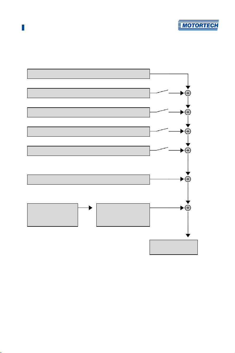
The figure below gives you an overview of the different functions of the timing correction, which
will be explained in more detail in the subsequent sections. Functions that can be
activated/disabled via the MICT are marked by a switch symbol. Depending on the device
version, some functions might not be available.
60 Rev. 03/2019
Page 61
7 Functions
Per schedule:
Base Timing
Speed Curve
Analog Voltage Input
Analog Current Input
Potentiometer
Global:
Ignition Timing Correction
Per cylinder:
Cylinder Individual
Offset
Limited by the
min./max. cylinder
individual offset
Limited by the
min./max. Timing
Rev. 03/2019 61
Page 62

7 Functions
7.4.1 Manual Timing Correction
The ignition controllers of the MIC5 series include two permanently installed overwind-protected
potentiometers for manually correcting the ignition timing. The max. range is defined with the
corresponding limits that are set by the user. Potentiometer A adjusts the ignition timing of
schedule A and potentiometer B adjusts the igniting timing of schedule B.
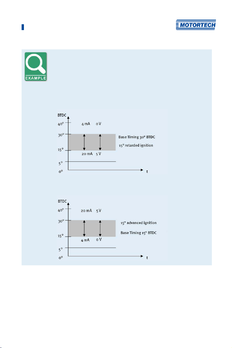
7.4.2 Analog Inputs
The timing point control can be adjusted with a linear current signal. This signal can be
supplied, for example, by a potentiometer, a pressure sensor for charging pressure, or a
detonation controller.
With the analog process signal (current loop signal) at the analog current input, the timing point
can be offset in the advanced or retarded direction within a defined range.
Similarly or additionally, the timing can also be influenced by an analog voltage signal at the
corresponding input.
The levels of the analog inputs can be set in the range from 0 mA to 20 mA and 0 V to 10 V. You
can make this configuration with the MICT. Please refer to the section Timing – Analog Inputs on
page 100.
At the voltage output (Analog Power), a configurable auxiliary voltage is supplied that can be
used for supplying power to external sensors.
62 Rev. 03/2019
Page 63
7 Functions
Configuration examples
In this example the analog inputs are configured in the Timing – Analog
Inputs window as follows:
– Input current: 4-20 mA
– Input voltage: 0-5 V
Characteristic 4-20 mA / 0-5 V – Ignition timing adjustment toward
retarded.
Characteristic 4-20 mA / 0-5 V – Ignition timing adjustment toward
advanced.
Rev. 03/2019 63
Page 64

7 Functions
7.4.3 Cylinder-to-Cylinder Alignment
The cylinder-to-cylinder alignment enables the user to change the timing for individual cylinders
to optimize their combustion.
You can enter the settings for the cylinder-to-cylinder alignment with the MICT. Please refer to
the chapter Cylinder Individual Offsets on page 149.
Use of measuring unit
Use this setup option only if a suitable measuring unit is available for
determining the optimum timing point, so that the result of a change can be
assessed immediately.
7.4.4 Speed Curve
To optimize the ignition, for example, during the start phase of the engine, a speed curve can be
defined for the MIC5 ignition controllers. To create this curve, up to eight adjustable speed
points are available.
You can configure the speed curve with the MICT. Refer to the section Timing – Schedule A/B –
General on page 102.
7.4.5 Ignition Timing Correction
There are two options for making corrections to the ignition timing:
– CANopen/Modbus/J1939
The field buses can be used to adjust the cylinder individual ignition timing points in 0.1°
increments by max. +/– 12.5 °crankshaft, restricted by the ignition timing point limits of the
current schedule.
– MICT via USB
Please refer to the section Runtime Adjustments – Timing on page 145.
7.5 Firing Angles
The min. distance between two ignition angles depends on the overspeed. The smallest ignition
spacing per output bank can be calculated using the following formula:
7.6 HV-Power Supply Error Monitoring
The voltage applied is monitored for excess voltage or low voltage by the integrated power
supply. For both errors a Power-Fail error is saved and the device shuts off.
64 Rev. 03/2019
Page 65

7 Functions
7.7 Output Monitoring
Electronic switches are used for the ignition outputs of the MIC5 ignition controller If one of
these switches is defective, this would lead to a primary short or a primary open output. This can
cause problems when operating the engine or can damage the engine. The function of the
outputs is therefore monitored and errors that occur are displayed in the runtime data in the
MICT or can be transmitted via field buses. Different alarms are available for monitoring the
misfire rate. It can also be defined that the ignition is switched off in the event of output errors.
Refer to the section Inputs/Outputs – Alarms on page 106.
7.8 Schedules A/B
The MIC5 ignition controllers offer two separate schedules for the parameterization of the
ignition timing and energy.
By closing input Schedule A/B, the listed parameter settings for schedule B can be selected. A
possible application for this is e.g. operation with different gases. If only one schedule is
configured, this is used regardless of the switch position.
You can configure the schedules with the MICT. Please refer to Timing – Schedule A/B – General
on page 102 and Timing – Schedule A/B – Energy on page 104.
Operational safety!
If you use schedules A and B, the advanced timing point should be linked to
schedule B (switch closure). If a wire ruptures, schedule A is automatically
selected with the retarded (and thus safer) timing point.
7.9 Alarms
The MIC5 ignition controllers include 16 freely configurable alarms in total. These alarms can be
freely allocated to the general purpose output (GPO) and set depending on the following
functions:
– Limit for speed exceeded/not reached
– Limit for engine operating hours exceeded/not reached
– Limit for spark plug operating hours exceeded/not reached
– Warning active
– Error active
– Limit for temperature exceeded/not reached
– Limit for supply voltage exceeded/not reached
– Limit for global ignition timing exceeded/not reached
– Limit on the analog voltage input exceeded/not reached
Rev. 03/2019 65
Page 66

7 Functions
– Limit on the analog current input exceeded/not reached
– Limit of the minimum spark duration exceeded/not reached
– Misfire rate (primary, single output) over limit
– Misfire rate (primary, all outputs) over limit
– Misfires per second (primary, all outputs) above threshold
– Consecutive misfires (primary, single output) above threshold
– Misfire rate (secondary, individual output) above threshold
– Misfire rate (secondary, all outputs) above threshold
– Misfires per second (secondary, all outputs) above threshold
– Consecutive misfires (secondary, single output) above threshold
A hysteresis can be defined for some alarms. You can configure the alarms with the MICT. Refer
to the section Inputs/Outputs – Alarms on page 106.
7.10 GPO: General Purpose Output
The function of the general purpose output (GPO) can be set as desired as normally closed or
normally open. The GPO can be used for the freely definable alarms.
You can enter the settings for the general purpose output with the MICT. Refer to the section
Inputs/Outputs – Alarms on page 106.
7.11 ASO: Auxiliary Synchronization Output
The ASO is an output of the MIC5 for synchronizing the MIC5 ignition controller and a connected
control unit. The possible applications include detonation control, valve control, and fuel
injection control.
The ASO signal is low-active, i.e. the pulse width is defined as the time difference between the
raising and falling edge (pulse width = t
configured engine rotation angle. With the variable pulse width, the values can be allocated to
the engine rotation angle. A max. of 20 pulses can be configured for this purpose.
The pulse width is known at the time of the active edge, as the falling edge of the signal
precedes the raising edge by the value of the pulse width. The controller calculates the duration
of the falling edge from high-level to low-level and then back to the starting value of the
high-level.
The ASO signal can be inverted via the configuration. It will then be high-active.
You can configure the auxiliary synchronization output with the MICT. Refer to the section
Inputs/Outputs – ASO1 (Auxiliary Synchronization Output) on page 108.
66 Rev. 03/2019
raising – tfalling). The raising edge of the signal marks the
Page 67
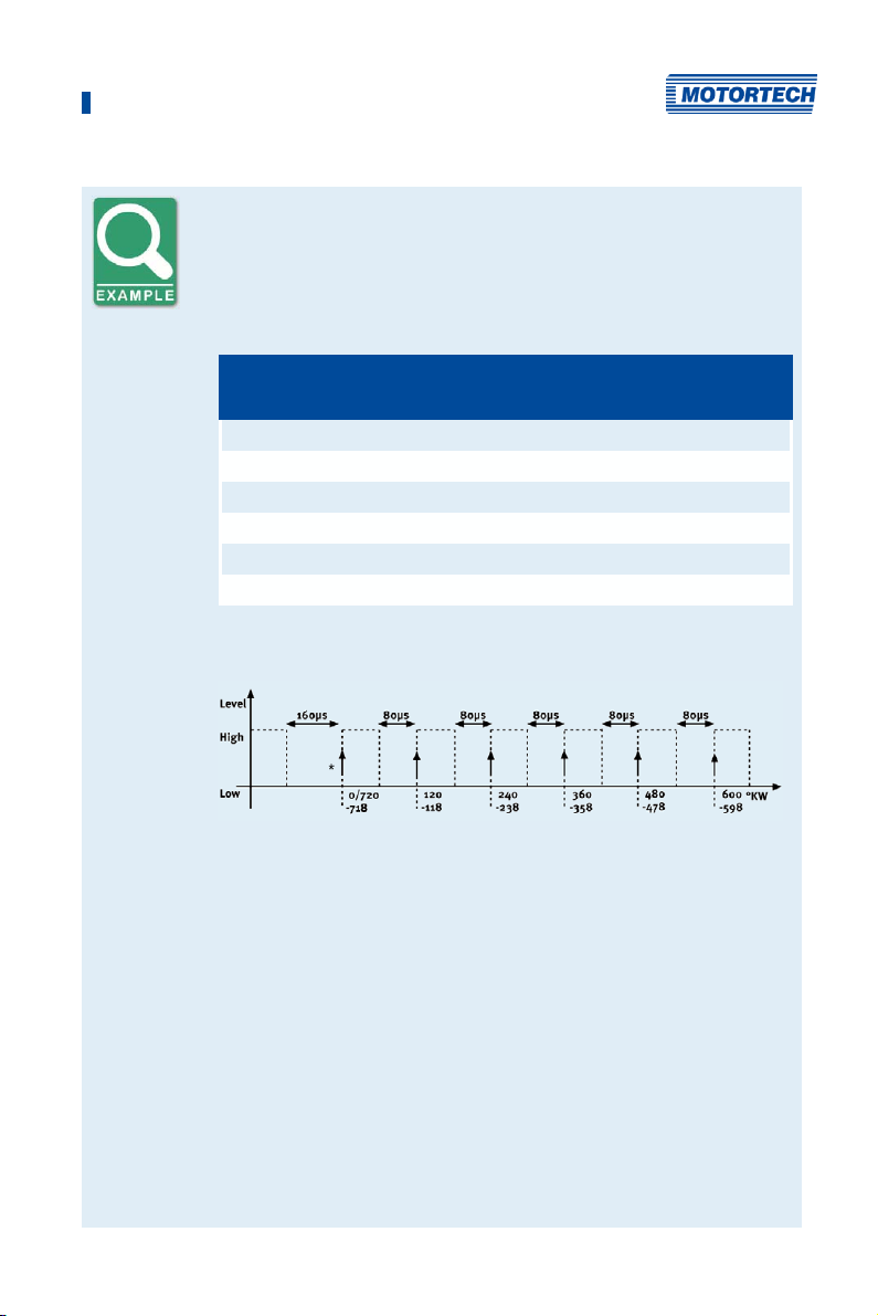
7 Functions
Application of the ASO signal
The following example will illustrate the application of the ASO signal:
– Four-stroke engine with 6 cylinders
– Ignition angle 120° - 120°
Synchronization between MIC5 and Valve Controller
Ignition angle in
Cyl.
°crankshaft
1 0/720 718 160
2 120 118 80
3 240 238 80
4 360 358 80
5 480 478 80
6 600 598 80
Schematic Representation (Standard Settings)
ASO signal in
°crankshaft
Pulse duration in
μs
*) active edge
The valve controller should receive the active edge of the ASO signal before
the top dead center of a cylinder. The first pulse duration should be twice
as long and thus mark the beginning of a cycle. The ASO signal generated
by the MIC5 increases by 2° each time before the ignition signal from Low
to High, as can be seen in the schematic drawing. This edge is analyzed by
the valve controller as the active edge.
The ASO signal drops in accordance with the configured pulse duration
from High to Low before the active edge. The valve controller then has
already measured the pulse duration of the active edge and can provide
information on the allocation of the signal. In the example shown here, the
first cylinder is marked with a pulse width of 160 µs versus 80 µs for other
cylinders. If the valve controller measures a pulse width of 160 µs, the
subsequent signal is therefore allocated to the first cylinder. The next
signal then corresponds with the second cylinder in the ignition sequence,
etc.
Rev. 03/2019 67
Page 68
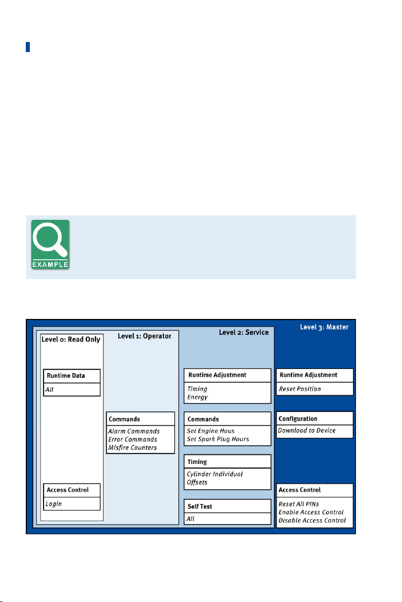
7 Functions
7.12 Ignition Energy
The ignition energy can be set separately for the start phase and normal operation. Here
different settings can be made for schedules A and B.
You can configure the ignition energy with the MICT. Please refer to the section Timing –
Schedule A/B – Energy on page 104.
7.13 Access Control
The MIC5 has four operating levels, three of which can be secured with different PINs. As a
default setting, the access control is not activated. If the access control for the MIC5 is activated,
it is independent from the access levels that control authorizations within the MICT.
Access control in the MICT and on MIC5
A user is logged in to the Advanced Service access level on the MICT. He
changes a configuration and would like to download the change to the
MIC5. Although he has the full authorization set in the MICT, he is prompted
to log in with the PIN for the Level 3 (Master) on the MIC5.
A variety of functions are at your disposal in the four operating levels of the MIC5 . The figure
below illustrates this:
68 Rev. 03/2019
Page 69

7 Functions
The following functions are available on the different levels:
– Level 0 (Read Only)
Enables read-only access for all users.
– Level 1 (Operator)
The user can operate the Alarm Commands, Error Commands, and the Misfire Counter on
this level.
– Level 2 (Service)
Only the Service level has access to modifications of the runtime adjustments for Timing and
Energy and the commands Set Engine Hours, Set Spark Plug Hours. The Cylinder Individual
Offsets and the Settings for Self Test can also be executed in this operating level.
– Level 3 (Master)
On this level, the Master can, in addition to the other adjustments, modify the Reset Position
and Reset All PINs and Enable/Disable Access Control. This authorization is also needed to
transfer a configuration to an ignition controller.
For information on the access levels in the MICT, refer to the section Access Levels in the MICT on
page 71.
Rev. 03/2019 69
Page 70

8 Settings via the MICT
MICT is an abbreviation for MOTORTECH Integrated Configuration Tool. With the MICT, you can
configure your ignition controller, and you can view and adjust the operating data of your
engine. When working with the MICT, you can press the F1 key at any time to access contextsensitive help.
If you are using a different version of the MICT than shown in the following sections, the scope of
functions may differ.
8.1 MICT System Requirements
For the installation of the MICT, the following minimum requirements must be fulfilled:
– x86-compatible PC, at least performance class Intel Pentium 4 with 2 GHz
– 128 MB free RAM
– 250 MB free disk space
– USB interface 1.1 or higher
– Display with a resolution of at least 1440 x 900 pixels (WXGA+)
®
– Microsoft
Windows 7, Windows 10
8.2 MICT Installation
The software for the installation of the MICT is on the storage device (USB flash drive or CD-ROM)
provided with the ignition controller.
To install the MICT, proceed as follows:
1. Start the installation:
– Via the menu:
Start the file Start.exe on the storage device. Start the installation routine of the MICT
via Software -> Install MICT.
– Directly from the storage device:
Start the installation routine of the MICT directly. It is on the storage device in the
subdirectory Installation and for example named as follows: MICT-2.0.0-setup.exe.
2. Run the installation.
Follow the instructions of the installation routine. Note that the license agreement terms
must be accepted before using the MICT.
3. Install the USB driver via the menu as well or directly from the storage device.
– Via the menu:
Software -> USB Drivers -> Install USB Drivers
– Directly from the storage device:
Start the exe file in subdirectory Drivers(e.g. CDM21226_Setup.exe).
The MICT is set up. You can connect your PC to the ignition controller via the USB
interface.
70 Rev. 03/2019
Page 71
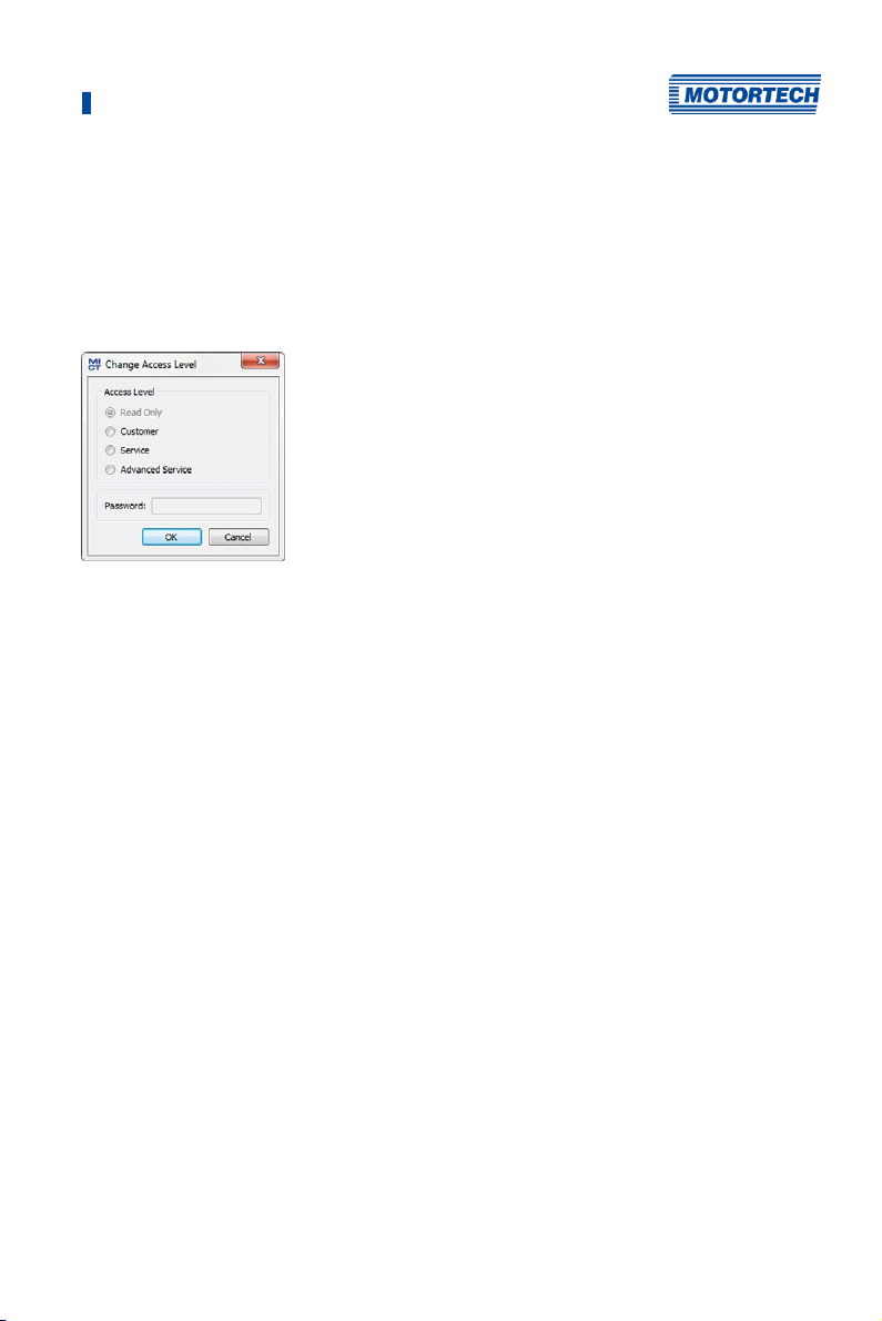
8 Settings via the MICT
8.3 Access Levels in the MICT
You can open the MICT on your PC via Start -> Programs -> MOTORTECH -> MICT 2.x.x -> MICT 2.x.x.
After opening the MICT, select the access level for which you have clearance. The access level
controls the options you have at your disposal in the MICT. The password required for access
can be obtained from your MOTORTECH contact person (refer to Customer Service Information on
page 165).
The following access levels are available:
– Read Only
On this level, the user can open a configuration and transfer it to the device. However, he
cannot make changes to the configuration. The user has read-only access to all other
settings.
– Customer
This level enables the configuration of the basic functions required for operation in addition
to the read-only function.
– Service
This level contains all functions for a standard installation.
– Advanced Service
This level offers full access to all functions of the MICT and is enabled and accessible for
specially trained personnel only.
The following sections describe the options at your disposal with the Advanced Service access
level. If you have registered for a different level, you cannot execute all functions shown.
Rev. 03/2019 71
Page 72
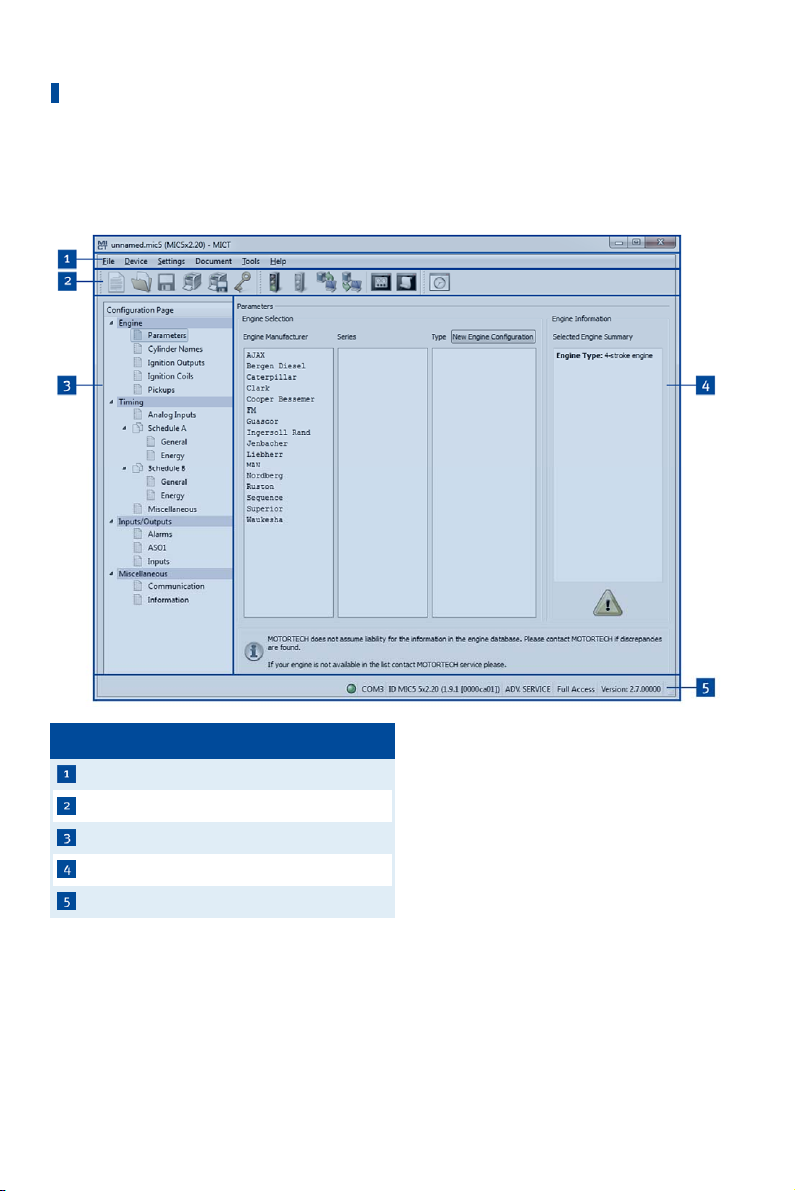
8 Settings via the MICT
8.4 Configuration Pages (Overview)
The configuration pages are divided into the following sections:
Item no. Area
The functions in the menu bar, navigation bar and the toolbar as well as the configuration
section will be described in the following.
72 Rev. 03/2019
Menu bar
Toolbar
Navigation bar
Configuration section
Status bar
Page 73
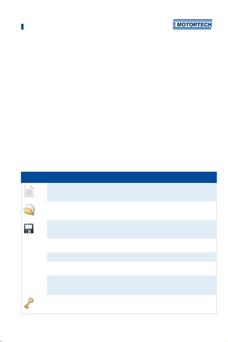
8 Settings via the MICT
The status bar provides you with the following information (from left to right):
– Status display
Indicates whether a connection is established with the device:
– Green: Connection established
– Red: The connection was interrupted and is being restored
– Gray: The connection is not established and is not being restored
– Indication of the interface being used for the connection to the device
– Indication of the device ID
– Indication of the access level of the user in the MICT
– Indication of the operating level for the MIC5 if access control has been activated and the
user has logged on with a PIN.
– Indication of the MICT program version
8.5 Menu Bar and Toolbar
The following functions are available to you via the symbols on the toolbar and the entries in the
menu bar:
Symbol Menu Function
File -> New
File -> Open
File -> Save /
File -> Save As
File -> Recent Documents
File -> Close
File -> Open trace
File -> Open pickup trace
File -> Change Access Level
Creates a new configuration.
Opens an existing configuration.
Saves the current configuration.
The last five configuration files used are offered
for selection.
Closes the current configuration.
Opens a runtime data record (trace file). Refer to
the section Runtime Data on page 114.
Opens a saved record of pickup signals (putrace
file). Refer to the section Pickup Trace on
page 78.
Changes the MICT access level for accessing the
configuration data and functions.
Rev. 03/2019 73
Page 74
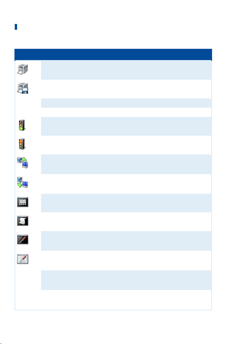
8 Settings via the MICT
Symbol Menu Function
File -> Print
File -> Print To PDF File
File -> Print Preview
File -> Quit
Device -> Connect
Device -> Disconnect
Device -> Download to device
Device-> Upload from device
Device -> Runtime data
Device -> Log
Device -> Runtime adjustments
Device -> Cylinder individual
offsets
Device -> Self test
Device -> Pickup trace
Prints the current configuration.
Prints the configuration to a PDF file.
Opens a print preview of the configuration.
Exits the MICT.
Connects to the device.
Cuts the connection to the device.
Downloads configuration data from the PC to the
device. Refer to Working with Configurations on
page 83.
Uploads configuration data from the device to
the PC. Refer to Working with Configurations on
page 83.
Opens the window Runtime Data. Refer to the
section Runtime Data on page 114.
Opens the window Log (Advanced Service only).
Refer to the section Log on page 142.
Opens the window Runtime Adjustments (Service
and Advanced Service only). Please refer to the
section Runtime Adjustments on page 143.
Opens the window Cylinder Individual Offsets
(Advanced Service only). Please refer to the
chapter Cylinder Individual Offsets on page 149.
Opens the window Self Test (Service and
Advanced Service only). For this read section Self
Test on page 77.
Loads the automatically recorded pickup signals
from the device. Refer to the section Pickup Trace
on page 78.
74 Rev. 03/2019
Page 75

8 Settings via the MICT
Symbol Menu Function
Device-> Set spark plug
operating hours
Device -> Set engine operating
hours
Device -> Set date and time
Device -> Send command ->
Reset misfire counters
Device -> Send command ->
Acknowledge operational error
(Keyboard shortcut: Strg+R)
Device -> Access Control
Device -> Temperature Extremes
Settings -> Language
Settings -> Online update
settings
Settings-> Database settings
Settings -> Temperature scale
Settings -> Display by cylinders
Document -> Schedule Curve
Opens the window Set spark plug operating
hours.
Opens the window Set Engine Operating Hours.
Opens the window Set Date and Time, in which
you can set the clock in the device.
The misfire counters of all ignition controller
outputs are reset and restarted. Misfires that
previously occurred at the outputs are no longer
displayed.
All operating errors are acknowledged. This can
only be implemented while the engine is not
running.
The setup for the access control to the MIC5 is
described in a separate section. Please read the
section Access Control for MIC5 on page 81.
Opens the window Temperature Extremes in
which the minimum and maximum temperatures
of the controller and output boards are
displayed.
Opens the window Select Language in which you
can change the interface language of the MICT.
Opens the window Online Update Settings. Refer
to the section Online Update Settings on page
76.
Opens the window Database Settings in which
various databases can be assigned as source for
the MICT.
Opens the window Select Temperature Scale, in
which you can change the unit for the
temperatures shown in the MICT.
Not currently used.
Opens the window Schedule. Please refer to the
chapter Schedule Curve on page 151.
Rev. 03/2019 75
Page 76
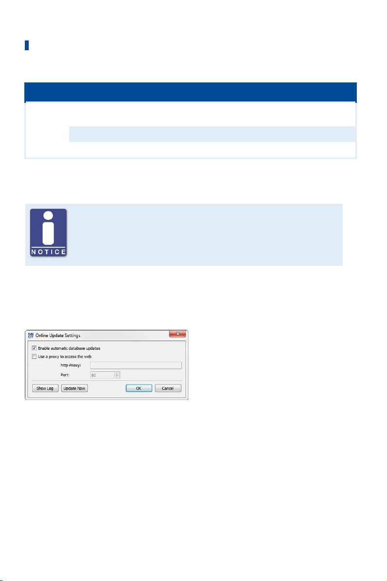
8 Settings via the MICT
Symbol Menu Function
Tools -> Coils
Help -> Help
Help -> About MICT
8.6 Online Update Settings
Perform regular online updates
MOTORTECH is constantly expanding its databases. Perform regular online
updates to make optimal use of the opportunities that the MIC5 provides.
The MICT uses data from an engine database and a coil database for the configuration. Such
data can be updated with automatic online updates. The settings for the update can be entered
with the following entry in the menu bar:
Settings -> Online update settings
Opens a database with information on
MOTORTECH ignition coils.
Opens the online help function.
Opens detailed information on the MICT.
You have the following options:
– Enable automatic database updates
Using the check box, you can enable and disable automatic online updates. As the default
setting, the online update is activated and is executed daily (if an internet connection is
established) at first start-up of the MICT.
– Use a proxy to access the web
Use the checkbox to activate settings for internet access via a proxy server, which you can
then set up by entering http-Proxy and Port.
76 Rev. 03/2019
Page 77
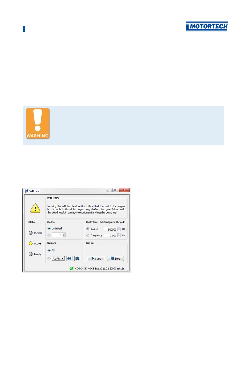
8 Settings via the MICT
– Show Log
With this button, you can open a window in which the online updates performed are logged.
– Update Now
With this button, you manually start an online update.
8.7 Self Test
Operational safety!
If you carry out a self test, it is essential for the gas supply to be switched
off and no more residual gas is left in the combustion chamber.
Non-compliance can result in damage to equipment or injury to persons.
You can run the self test via the MICT to check the order of the wiring and the connection
between the ignition controller outputs and the spark plugs.
Proceed in the MICT as follows:
Device -> Self test
The following information is provided:
Status
The status displays indicate whether the ignition controller is ready for the self test.
– Locked
The ignition controller is in a state in which no self test can be done. For example, there is an
error or a configuration is currently being downloaded into the device.
Rev. 03/2019 77
Page 78

8 Settings via the MICT
– Active
The self test is running.
– Ready
The ignition controller is ready and the self test can be started.
You have the following options:
– Cycles
Determine whether the self test should run unlimited or be terminated after a defined
number of cycles.
– Outputs
Define whether all outputs or only a defined output should be fired during the self test.
– Cycle Time - All Configured Outputs
Specify the cycle time either as a period or frequency. The value entered always refers to a
complete cycle. That means that all outputs that are configured are fires once per cycle. If
you only set one output for the self test, this would still only fire once per cycle.
– Control
Start or stop a self test using the corresponding buttons.
8.8 Pickup Trace
The traces of the pickup signals support you in checking the behavior of the used pickup and
thus, for example, to detect and analyze irregularities or failures.
Pickup signals are automatically recorded by the ignition controller as soon as they are detected
at the configured inputs. Ten further signals are recorded if an error occurs during operation
(cumulative across all inputs). The recording is then stopped so that the pickup signals just
before the error can be analyzed. The records can be downloaded from the device at any time.
Proceed in the MICT as follows:
Device -> Pickup trace
78 Rev. 03/2019
Page 79
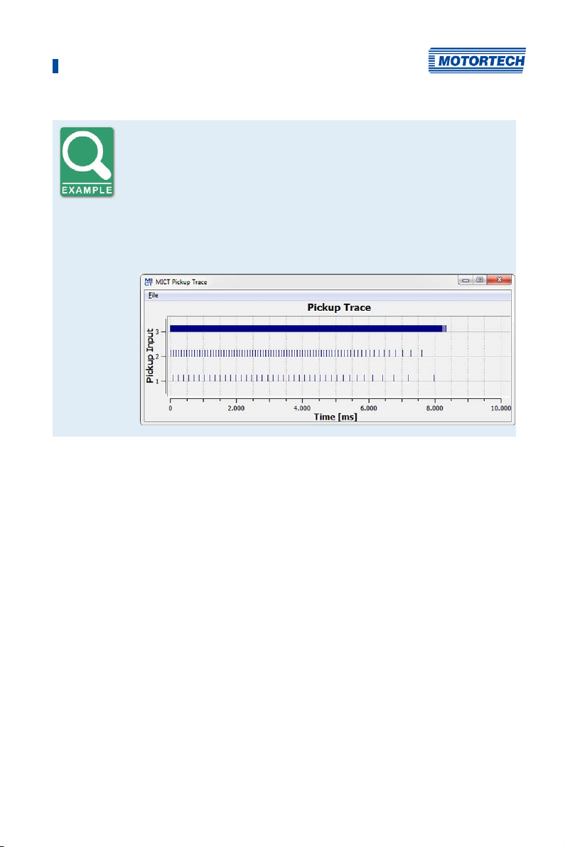
8 Settings via the MICT
Pickup trace
Example of a pickup trace for a configuration with three pickups:
– Pickup input 1 (cam):
Operation
The following options are available via the menu in the window:
– Open
Opens a previously saved pickup trace.
– Save as
Saves a pickup trace as a .putrace file.
– Close
Closes the pickup trace.
Single event from the camshaft
– Pickup input 2 (reset):
Single event from the crankshaft
– Pickup input 3 (trigger):
Trigger disc of type N with 160 events from the crankshaft
Rev. 03/2019 79
Page 80
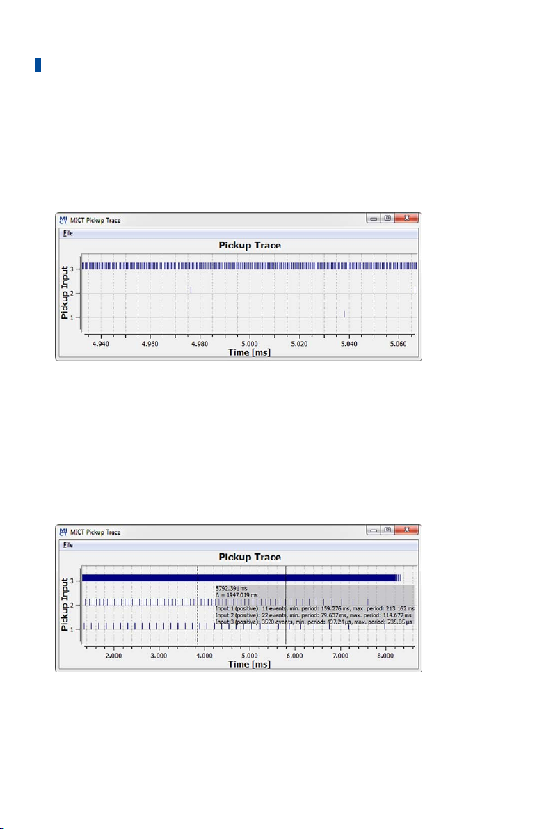
8 Settings via the MICT
There are the following options for the display of the pickup signals:
– Zoom In/Out
Using the mouse scroll wheel you can zoom in and out of the displayed record range.
Alternatively you can also use the plus and minus keys on the keyboard. With the zoom
function, you can e.g. analyze the trigger signal more precisely (pickup input 3 in the
drawing).
– Move displayed range
With the right mouse button pressed you can move the displayed range along the time axis.
– Measuring
You can measure distances and the number of events in the displayed range by holding
down the left mouse button to highlight a section. You can find the following information in
the window:
– Position on the time axis
– Time difference () between the two selected points
– Number of events counted in the selected period
80 Rev. 03/2019
Page 81

8 Settings via the MICT
Error Analysis
The pickup traces support you, for example, in analyzing the following errors:
– Configuration of the pickup does not agree with the wiring (e.g. trigger disc configuration,
allocation of the inputs, allocation of the shafts). In this case, you should compare the
values configured with the signals recorded (see Engine – Pickups on page 96).
– One or more pickups have failed.
Pickup trace
The pickup signals are only recorded on the inputs that are configured in
the MICT. If the configuration of the pickup inputs is not valid (e.g. three
signals from the same shaft), no signals are recorded.
8.9 Access Control for MIC5
If the access control to the MIC5 is activated, access to the following areas is possible with a PIN
only:
– Runtime Adjustment (Reset, timing, energy, secondary voltage estimation calibration and
secondary short calibration)
– Commands (Alarms, error commands, set engine/spark plug operating hours, and self test).
– Configuration (Transferring a configuration to the MIC5)
The access control regulates the accesses to the device via the MICT. For explanations
concerning access control of the MIC5 and the delimitation of the access levels in the MICT, refer
to section Access Control on page 68.
The access control functions can be accessed in the menu bar via:
Device -> Access Control
8.9.1 Enable/Disable Access Control
Enable/Disable access control
As a default setting, the access control is not activated, and all PINs are set
to 0000. Once the access control has been activated, and the PINs were
changed, these PINs will continue to be used. To activate the access control
again, you will need the PIN for level 3 (Master). It is therefore
recommended to reset all PINs before disabling.
If that was not done, or a system must be unlocked for another reason, a
request key can be issued in the MICT. Refer to the section Reset all PINs on
page 82.
Rev. 03/2019 81
Page 82

8 Settings via the MICT
To enable or disable the access control, proceed as follows:
1. Open the input dialog via Device -> Access Control -> Enable or Disable access control.
2. Enter the PIN for the level Master (Level 3).
3. Confirm the input with OK.
8.9.2 Login/Logout
If the access control is activated, you are prompted to log in if you want to execute functions that
are allocated to a specific operating level. In addition, you can log in specifically to an operating
level via the menu bar.
To log into a specific operating level, proceed as follows:
1. Open the input dialog via Device-> Access Control -> Login.
2. First select the level you wish to log on to.
3. Enter the PIN for the desired level.
4. Confirm the input with OK.
You are now logged into the corresponding level and can execute all functions that are
allocated to this operating level without having to log in again.
After completing the log-in, you can log out again as follows:
Device -> Access Control -> Logout
8.9.3 Changing the PIN
To change the PIN for a specific operating level, proceed as follows:
1. Open the input dialog via Device -> Access Control -> Change PIN.
2. First select the level for which you wish to change the PIN.
3. Enter the current PIN for the desired level.
4. Enter the new PIN in the two subsequent fields.
5. Confirm the input with OK.
The PIN for this operating level has now been changed.
8.9.4 Reset all PINs
To reset all PINs, proceed as follows:
1. Open the input dialog via Device -> Access Control -> Reset all PINs.
2. If you are not yet logged into the Master (level 3) level, you will be prompted to log in with
the relevant PIN.
3. Confirm the input with OK.
4. To reset all PINs, you will be prompted again to enter the PIN for the level Master (Level 3).
82 Rev. 03/2019
Page 83

8 Settings via the MICT
5. Confirm the input with OK.
All PINs are now reset to the value 0000.
To reset all PINs, you need the PIN for the level Master (level 3). To be able to unlock a system in
case of emergency that was locked in this way, you have the following option:
1. In the menu bar, select the entry Device -> Access Control -> Get reset all PINs request key to
open a window with the same name.
2. Send the request key with the serial number to your service contact person at MOTORTECH
(refer to Customer Service Information on page 165). This key is valid only for the respective
controller and only for a certain amount of time.
Your information will be verified, and you will receive an authorization key from your
contact person.
3. From the menu bar, select the entry Device -> Access Control -> Set reset all PINs
authorization key to open a window with this name.
4. Enter the authorization key received in the input field.
5. Confirm the input with OK.
If the input was correct, all PINs are reset to the default value 0000.
8.10 Working with Configurations
To ensure that the MIC5 correctly interprets incoming data and correctly controls the ignition
system, it requires information about the engine and the ignition system. This information is
stored in the MIC5 as configuration data.
You can use the MICT to perform the following for these configurations:
– Create
– Open
– Edit
– Save as a file
– Download to the MIC5
– Upload from the MIC5
Rev. 03/2019 83
Page 84
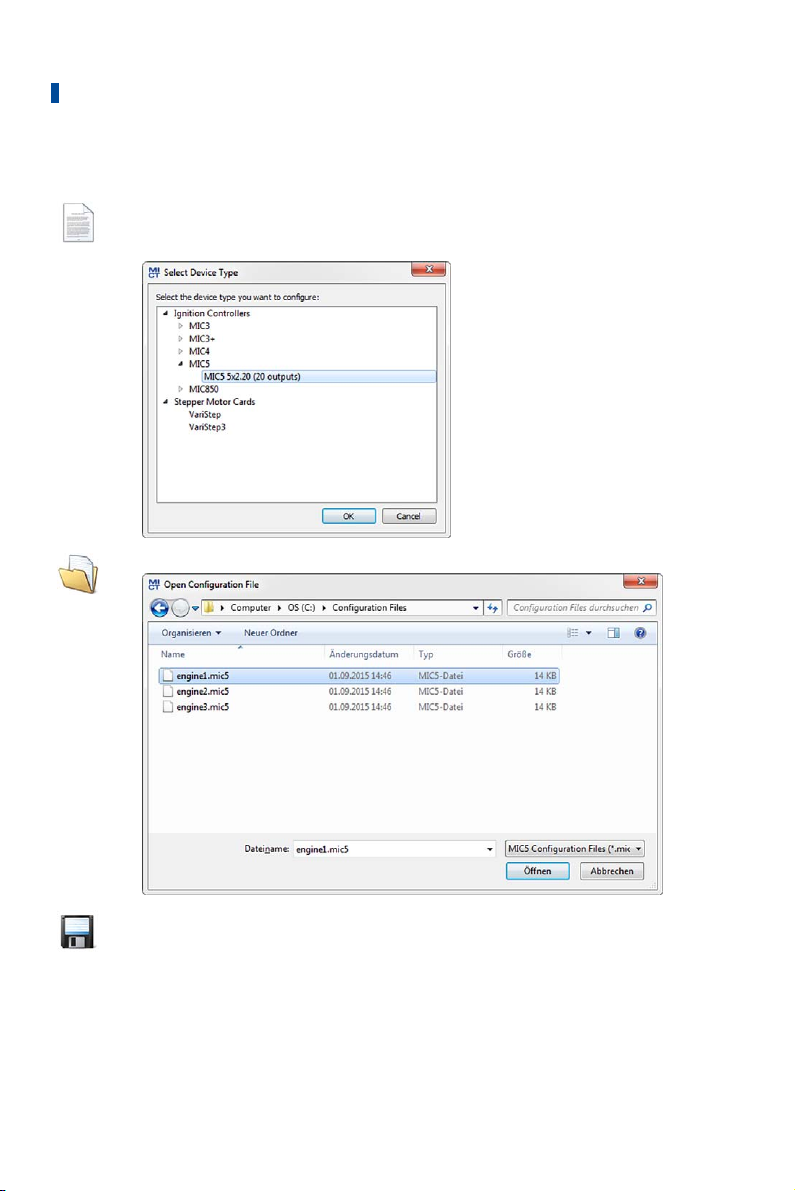
8 Settings via the MICT
8.10.1 Create, Open, Save
Click on the symbol to create a new configuration and select the corresponding
device type. The device type corresponds to the first five digits of the
arrangement number, which you can find on a label on your device.
Click on the symbol to open a saved configuration.
Click on the symbol to save the configuration currently displayed in the MICT to
a storage device.
84 Rev. 03/2019
Page 85
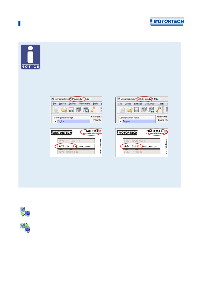
8 Settings via the MICT
Compatibility of the configuration files
Configuration files are only compatible for the respective device type, even
if the file extension is identical. For example, files created for a MIC3 cannot
be downloaded to a MIC3+ and vice versa.
To use a configuration for another device, the series and the first four digits
of the arrangement number must match. This information can be found in
the title bar of the configuration and on the respective device:
MIC3
If, for example, a system is to be changed from a MIC3 to a MIC3+, the
configuration of the MIC3 can be saved as a PDF file. Then a new
configuration file must be created for the MIC3+ and the values from the
PDF file must be entered. Alternatively, the MICT can be opened twice and
the values transferred to a newly created configuration file.
8.10.2 Upload, Download
Click the symbol to upload the current configuration from the MIC5 to the MICT.
If applicable, the MICT first establishes a connection to the MIC5 connected.
Click on the symbol to download the configuration set in the MICT to the MIC5.
This function can only be executed while the ignition is not active. This action
overwrites the existing configuration on the device. If applicable, the MICT first
establishes a connection to the MIC5 connected.
MIC3+
Rev. 03/2019 85
Page 86
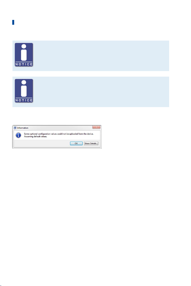
8 Settings via the MICT
Existing configuration is cleared!
If you download a configuration to a MIC5, the previous configuration is
deleted and the new settings are immediately implemented.
Runtime adjustments
If you change a configuration stored in the MIC5 via runtime adjustments,
the configuration must be re-uploaded from the device so that the changes
are displayed in the MICT's configuration views.
8.10.3 Compatibility Information
If you upload a configuration from the MIC5 to the MICT that does not correspond to the status of
your MICT, or if you open this type of configuration in the MICT, the following situations may
occur:
– No values are present in the configuration for certain MICT functions. The MICT assumes the
standard values for these functions.
– The configuration contains function values that are not support by the MICT.
The following situations can occur if you download a configuration from the MICT to a MIC5
whose firmware does not correspond to the status of your MICT:
– No values are present in the configuration for certain firmware functions. The firmware
continues to use the preset values for these functions.
– The configuration contains function values that are not support by the firmware.
If you download a configuration into the MIC5 and are notified of functions that are not
supported by the MICT, you should check the MIC5 settings. Re-upload the configuration from
the MIC5 to the MICT. You can then see which settings are not transmitted to the MICT.
Perform a firmware update, if necessary, and/or update your MICT so that you can use all the
MIC5 functions without restriction.
86 Rev. 03/2019
Page 87
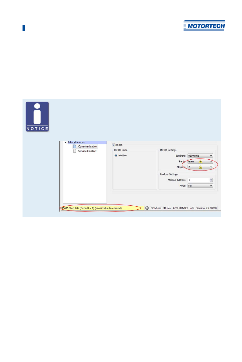
8 Settings via the MICT
8.11 Configuration
The window opens after you select the device type for a new configuration or an existing
configuration or have uploaded one from the ignition controller. You can make changes to the
configuration by selecting an entry from the navigation bar. The corresponding configuration
data are then displayed in the configuration section and can be processed. The following
sections will describe the settings and adjustments you can implement in the different areas.
Indication of invalid entries
An invalid selection or invalid input values are highlighted by pulsating
warning signs on the configuration pages of the MICT. Additional
information is provided in the status bar.
Example:
Rev. 03/2019 87
Page 88
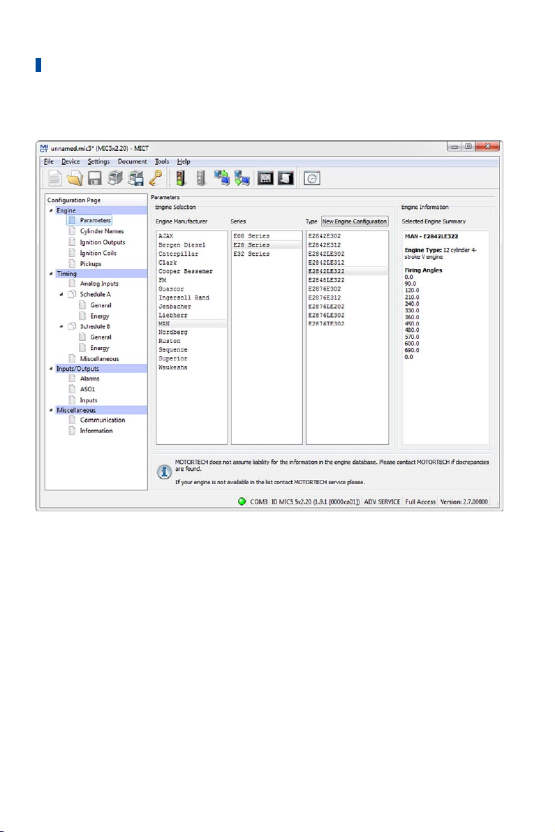
8 Settings via the MICT
8.11.1 Engine – Parameters
Engine Selection
The MICT holds an engine database with data from various manufacturers and model series.
Select the desired engine manufacturer, series, and type by clicking on the corresponding fields.
88 Rev. 03/2019
Page 89
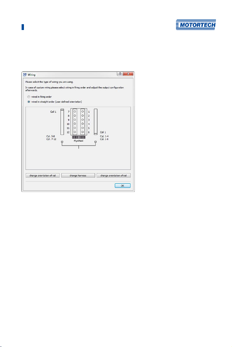
8 Settings via the MICT
Wiring in firing order is assumed as standard. If straight order wiring is supported for the
selected engine, the Wiring dialog opens and you have the opportunity to adapt the output
configuration.
You can use straight order wiring, if:
– Wiring takes place via a corresponding MOTORTECH wiring harness and a MOTORTECH
wiring rail. The harness is marked with the following information: PLEASE NOTE! The firing
order needs to be configured directly in the ignition controller. The ignition coils on the
wiring rail are marked with Connector Pin 1 to Connector Pin X. The position of coil1 on the
wiring rail is marked in the view Wiring.
– Wiring of the ignition controller is done corresponding to the instructions in section Straight
Order Wiring of the Ignition Outputs on page 56 (for example with an open wiring harness or
via a junction box).
The configuration of the ignition outputs is automatically adapted corresponding to your
selection. If you want to use a different wiring, these settings must be adapted appropriately.
If the pertinent engine is not available in the database, settings can also be entered by selecting
the corresponding sequence. For this purpose, click on the entry Sequence in the column Engine
Manufacturer and select the firing stroke in the column Series, then the number of cylinders,
and the ignition offset of the engine as needed. After making your selections, the right hand
section Engine Information will display a summary of the parameters selected.
The summarized data are transferred to the subsequent configuration page Ignition Outputs.
The values displayed there can only be changed by users with authorization to access the
Advanced Service level.
Rev. 03/2019 89
Page 90
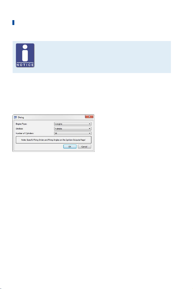
8 Settings via the MICT
Engine database
MOTORTECH does not assume liability for the information in the engine
database. Please contact MOTORTECH if discrepancies are found.
New Engine Configuration
Staff with the authorization for the Advanced Service level additionally has the option for
entering the engine data manually, i.e., without selecting entries from the engine database. For
this purpose, click on the New Engine Configuration button and select the engine type, number
of cycles, and number of cylinders in the dialog box opening up. Additional information can be
entered on the configuration page Ignition Outputs.
90 Rev. 03/2019
Page 91
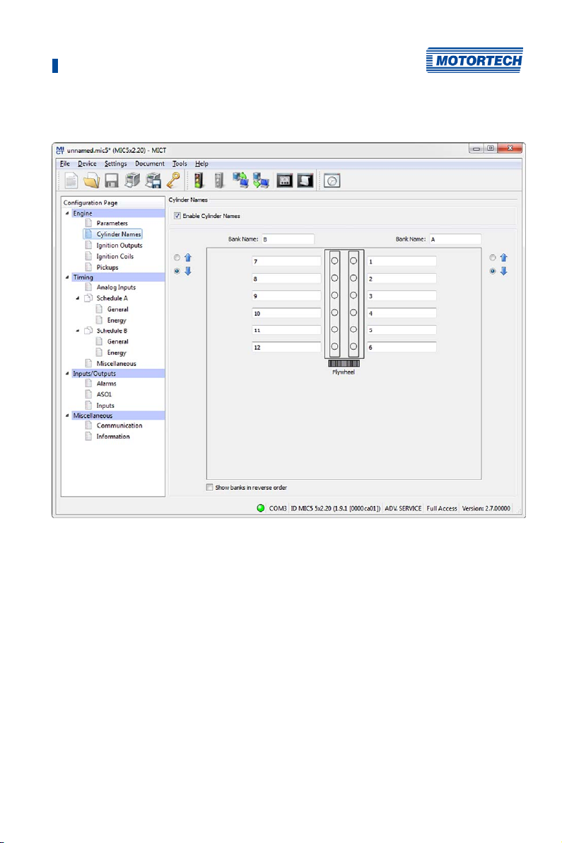
8 Settings via the MICT
8.11.2 Engine – Cylinder Names
To facilitate the allocation of the cylinders during the configuration of the ignition outputs, you
can individually name each cylinder. The schematic representation of the plan view of the
selected engine supports you in this. Enter the following settings:
– Enable Cylinder Names
Activate the checkbox in order to assign cylinder names. In order to use this function, the
number of cylinders must be defined. Establish the number of cylinders either by using a
configuration from the engine database or by creating a new engine configuration via the
corresponding button. Refer to the section Engine – Parameters on page 88. If you have
activated the checkbox, the assigned cylinder names must also be assigned to the
corresponding ignition outputs, before the configuration is transferred to the ignition
controller. Otherwise there will be an error message. Refer to the section Engine – Ignition
Outputs on page 92.
– Bank Name
Enter a name for the respective cylinder bank.
Rev. 03/2019 91
Page 92
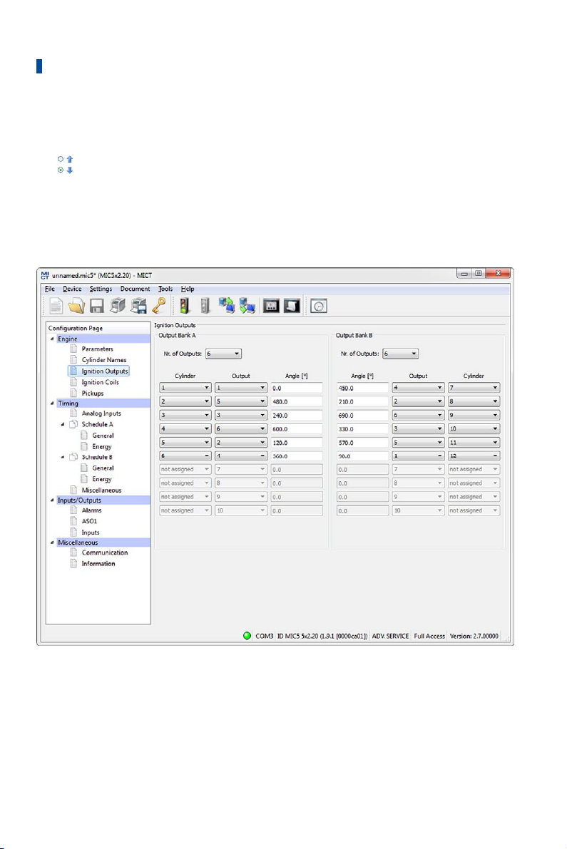
8 Settings via the MICT
– Cylinder Names
Enter a name for the respective cylinder.
–
currently not used
– Show banks in reverse order
currently not used
8.11.3 Engine – Ignition Outputs
Make adjustments to the following settings as needed:
– Number of Outputs
Select the number of outputs for the respective output board.
– Column: Cylinder
Select a cylinder. The displayed names are specified on the configuration page Engine –
Cylinder Names.
92 Rev. 03/2019
Page 93

8 Settings via the MICT
– Column: Output
Select the number of the respective output.
– Column: Angle
Enter the firing angle for each output.
Default Application
If you select from the engine database, the data stored for the selected configuration are
displayed. These data can only be changed by personnel with access to the Advanced Service
level.
New Engine Configuration
If you have created a new engine configuration on the configuration page Engine – Parameters
using the corresponding button, first the number of outputs corresponding to the number of
cylinders are distributed to the output bank A and output bank B. Selecting the number of
outputs enables access to the fields for the configuration of the outputs. We recommend that
you distribute the number of outputs evenly among the output banks and allocate the larger
number to the A output bank if the number is uneven.
By default, the ignition outputs are distributed so that cylinder 1 of the firing order is always
allocated to output bank A with a firing angle of 0°. The further distribution is implemented by
alternating between output bank A and B. The firing angle for each output results from the
addition of the firing interval to the respective previous output.
Operational safety!
Never connect more than one output to each ignition coil, as the output
boards can otherwise be damaged!
The allocation of outputs on the output banks to contacts of the output connector of the device
and the cylinders is determined by the wiring. The user must take the wiring into account during
the configuration; it cannot be checked by the software.
Interval between two ignitions
The interval between two ignitions on an output board must be min. 2.8 ms.
During the check, the configured overspeed is used in the calculation.
Rev. 03/2019 93
Page 94
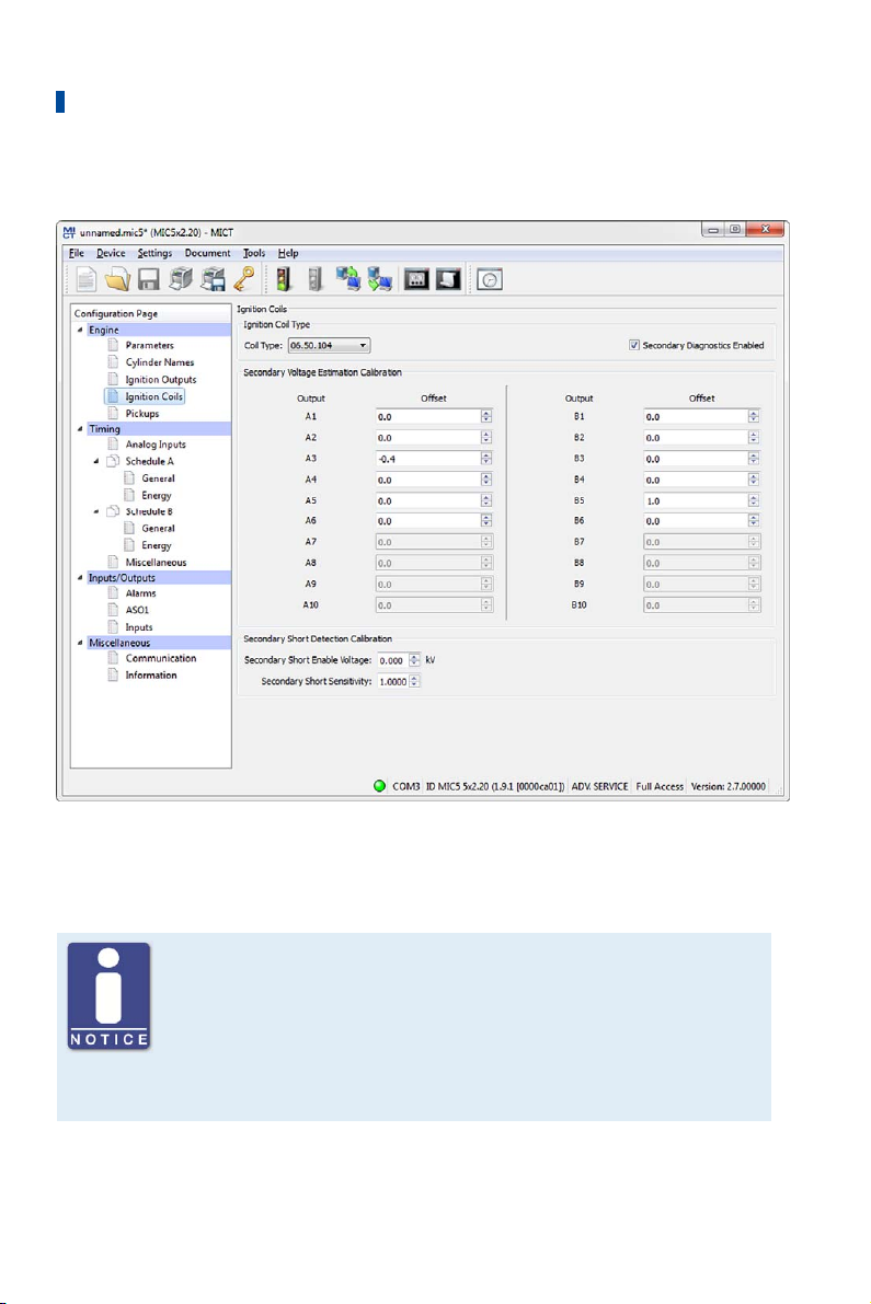
8 Settings via the MICT
8.11.4 Engine – Ignition Coils
Ignition Coil Type
Select the ignition coil type from the drop-down list. (Without this selection the configuration
cannot be downloaded to the MIC5.)
Only use measured ignition coils
To operate the MIC5, only ignition coil types measured by MOTORTECH may
be used. All ignition coils used must correspond to the part number
selected in the drop-down list. Different coil types must not be mixed and
also no equivalent or replacement types may be used.
If a coil type used is not in the drop-down list, then the MIC5 is currently not
used.
94 Rev. 03/2019
Page 95

8 Settings via the MICT
Secondary Diagnostics Enabled
The secondary diagnosis can be deactivated and activated for ignition coils that support this
function. If the ignition coil does not support this function, the secondary voltage estimation
calibration and the of the secondary short calibration are not available.
Secondary Voltage Estimation Calibration
A correction value without units can be set for the secondary voltage estimation for every
configured output to increase the accuracy of the secondary voltage estimation for each
individual cylinder. This allows, for instance, different cable lengths on the engine to be
compensated.
The values of the secondary voltage estimation can be changed for each individual cylinder. The
value range depends on the ignition coil. 0.0 is set as the standard value for all cylinders. You
can adjust the secondary voltage estimation while the engine is running in the runtime
adjustments (refer to Runtime Adjustments – Secondary Voltage Estimation Calibration on
page 147).
Secondary Short Detection Calibration
The starting voltage and the secondary short detection sensitivity can be adjusted. You can
adjust the secondary short detection in the runtime adjustments while the engine is running
(refer to Runtime Adjustments – Secondary Short Calibration on page 148).
Secondary Short Enable Voltage
Set the average ignition voltage required to activate the secondary short-circuit monitoring:
– The secondary short detection is always activated at a value of 0 kV.
– The secondary short detection is always deactivated at a value of 65.535 kV.
Secondary Short Sensitivity
The permitted value range depends on the set ignition coil.
Set the sensitivity of the short-circuit detection e.g. as follows:
– The sensitivity is high at a value of 0.98.
– The sensitivity is low at a value of 1.02.
Rev. 03/2019 95
Page 96
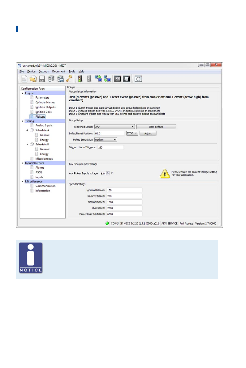
8 Settings via the MICT
8.11.5 Engine – Pickups
Active pickups
Check when using active pickups that the auxiliary supply voltage is
configured for your application.
Pickup Setup Information
The settings made in the section Pickup Setup were summarized once again in the section
Pickup Setup Information.
96 Rev. 03/2019
Page 97
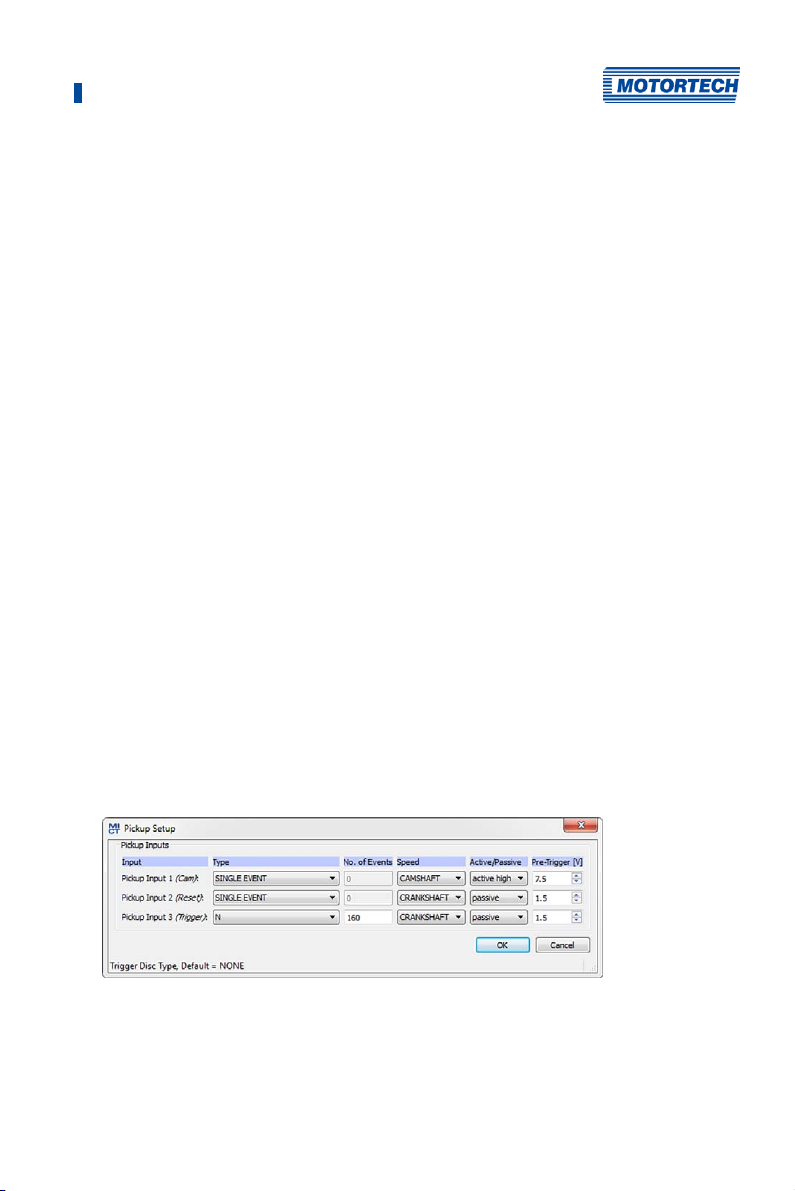
8 Settings via the MICT
Pickup Setup
Enter the following settings in this section:
– Predefined Setup
Select the pickup configuration suitable for your application from the list. The
configurations available for selection depend on the previously entered settings.
– Index/Reset Position
Enter the distance between the first event after the set index/ reset marking and top dead
center. With the button Adjust, you can enter the measured firing angle for a given nominal
value. The system calculates the difference from these values, which is added to or
subtracted from the index/reset position.
– Pickup Sensitivity
Open the pick list and select the desired sensitivity level for the pickup. This setting
overwrites the value of the pre-trigger voltage if the latter was defined in the user-defined
pickup setup.
– High
The signal processing starts at low engine speeds. This setting can result in increased
susceptibility to failure.
– Medium
Default setting for MICT. This is a trade-off between start-up speed and sensitivity.
– Low
The signal processing does not start until high engine speeds are reached. This setting
can result in reduced susceptibility to failure.
– Trigger/Cam No. of Triggers
Enter the number of events. The input Cam or Trigger is automatically selected by the MICT
and is governed by the selection of the pre-defined pickup settings.
– User-defined
Staff authorized to access the Advanced Service level can, in addition to the standard
settings access, use a manual setup option by clicking on the button User-defined.
Rev. 03/2019 97
Page 98

8 Settings via the MICT
– Type
You can select the type of events that will occur on this input for each pickup input. Type
and number of events are defined by the discs or ring gears used. If you decide not to
use a pickup input, select the entry None from the list. You can set the following types:
N
Disc, which causes a uniformly distributed number (N) of events (per rotation), e.g. a
ring gear with 160 teeth (N=160).
N+1
Disc type N with one additional event, e.g. a disc with 12 teeth and one additional tooth
for the index signal (N=12).
N+1 extended index range
Disc type N with an additional event, e.g. with one disc with 12 teeth and one additional
tooth for the index signal (N=12). The permitted range for the index signal is expanded
to 75 % of the tooth period. An incorrect direction of rotation of the engine cannot be
detected by this setting.
N-1
Disc type N, where one event is missing, e.g. a ring gear with 160 teeth on which one
tooth was removed (N=160). This missing event is used to determine the index signal
N-2
Disc type N, where two consecutive events are missing, e.g. a ring gear with 60 teeth on
which two teeth located next to each other were removed (N=60). This missing event is
used to determine the index signal.
N Magnets, Single Magnet
You will always use these two types together for a disc with magnets having opposite
polarity. A magnet with a fixed number of magnets (N), all of which are arranged at equal
distances on the disc, has a reverse polarity. Thus, the disc supplies two signals that
can be analyzed by a pickup.
Single Event
Disc that supplies a single event, e.g., a disc with one tooth or one magnet.
– Number of Events
Enter the number of events that occur on the pickup if more than one event is expected.
For the types N+1 and N-1, enter the value for N and not the total number of events. With
the type N Magnets, the number of magnets with identical polarity must be entered.
The number of events must lie between 3 and 500. Additionally, it must be taken into
account that the sum of the frequencies at the pickup input does not exceed the limit of
10 kHz at the pre-set overspeed.
– Speed
Select whether the respective pickup will pick up the signal off the camshaft or the
crankshaft.
98 Rev. 03/2019
Page 99

8 Settings via the MICT
– Active/Passive
Select the pickup to be used from the pre-defined pick list:
Passive
passive pickup
Active (low)
active pickup with high level as quiescent level
Active (high)
active pickup with low level as quiescent level
– Pre-Trigger
Enter a value between 0.1 V and 7.5 V for each pickup to set the pickup sensitivity level.
Signals that fall short of the set voltage will not be analyzed. A low pre-set value
therefore results in a high sensitivity level, a high value results in a low sensitivity level.
Pickup setup information
The respective latest setting in the area of the pre-defined or arbitrary
pickup settings is transferred to and displayed under Pickup Setup
Information.
Aux. pickup supply voltage
Enter the supply voltage with which the active pickup is to be operated. A value between 5 and
24 V is possible.
Speed Settings
Enter the following settings in this section:
– Ignition Release
Enter the release speed for the ignition at which the first ignition is to fire. The value shall
not exceed 1/7 of the nominal speed.
– Security Speed
Enter the security speed (max. half the nominal speed). Below the value entered, the ignition
can be switched on and off as desired. If the ignition is deactivated during operation above
the set speed, the ignition cannot be immediately reactivated. Only when the ignition no
longer reads a speed, i.e., the engine has come to a standstill, can the ignition be
reactivated.
– Nominal Speed
Enter the nominal speed at which your engine is to be operated. With engines that are to be
operated with variable speeds, the max. speed of the operating range must be entered.
– Overspeed
Enter the speed at which the ignition is to be shut off as overspeed protection. With engines
that are to be operated with variable speeds, a speed above the operating range must be
entered.
Rev. 03/2019 99
Page 100
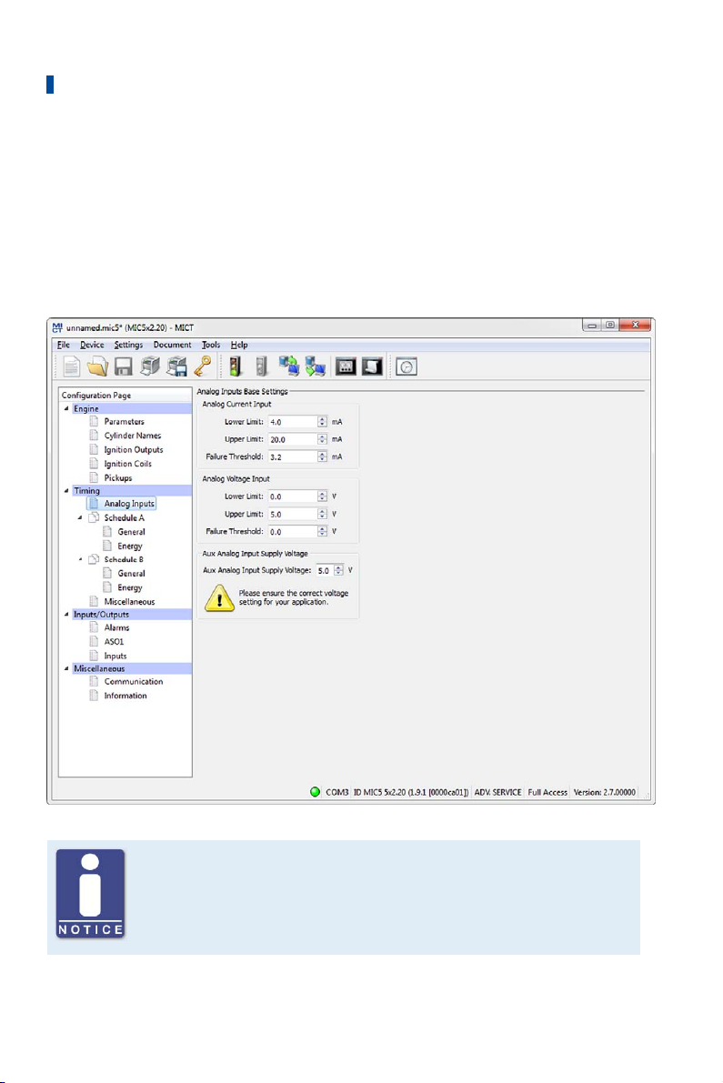
8 Settings via the MICT
– Max. Power-on Speed
Enter the maximum permitted start speed at which the MIC5 starts sending ignition pulses.
A value of 6000 rpm is set as the default value: The MIC5 can be activated at the starter
speed and immediately send ignition pulses.
For a value of 0 rpm the MIC5 can only start sending ignition pulses once it has registered
that the engine is at a standstill.
8.11.6 Timing – Analog Inputs
Auxiliary supply voltage
Check with the configuration of the analog inputs, that the set auxiliary
supply voltage corresponds to your application.
100 Rev. 03/2019
 Loading...