

Page 1
Level 1 and 2 Service Manual
6809506A96-O
TM
MOTORIZR
Z6
Digital Wireless Telephone
GSM 850/900/1800/1900 MHz, EDGE, GPRS
Page 2

MOTOROLA and the Stylized M Logo are registered in the US Patent & Trademark Office.
All other product or service names are the property of their respective owners.
The Bluetooth trademarks are owned by their proprietor and used by Motorola, Inc. under license.
© Motorola, Inc. 2007.
All rights reserved.
Mobile Devices Business,
Sawgrass International Concourse
789 International Parkway
Room S2C
Sunrise, FL 33325-6220
Page 3

1 and 2
Level 1 and 2 Service Manual Contents
6809506A96-O
Z6
Contents
Contents
Introduction . . . . . . . . . . . . . . . . . . . . . . . . . . . . . . . . . . . . . . . . . . . . . . . . . . . . . . . . . . . . . . . . . . . . . . . . . . . . . . . . . 4
Product Identification . . . . . . . . . . . . . . . . . . . . . . . . . . . . . . . . . . . . . . . . . . . . . . . . . . . . . . . . . . . . . . . . . . . 4
Product Names . . . . . . . . . . . . . . . . . . . . . . . . . . . . . . . . . . . . . . . . . . . . . . . . . . . . . . . . . . . . . . . . . . . . . . . . 4
Product Changes . . . . . . . . . . . . . . . . . . . . . . . . . . . . . . . . . . . . . . . . . . . . . . . . . . . . . . . . . . . . . . . . . . . . . . . 4
Regulatory Agency Compliance . . . . . . . . . . . . . . . . . . . . . . . . . . . . . . . . . . . . . . . . . . . . . . . . . . . . . . . . . . . 4
Computer Program Copyrights . . . . . . . . . . . . . . . . . . . . . . . . . . . . . . . . . . . . . . . . . . . . . . . . . . . . . . . . . . . 5
About This Service Manual . . . . . . . . . . . . . . . . . . . . . . . . . . . . . . . . . . . . . . . . . . . . . . . . . . . . . . . . . . . . . . 5
Warranty Service Policy . . . . . . . . . . . . . . . . . . . . . . . . . . . . . . . . . . . . . . . . . . . . . . . . . . . . . . . . . . . . . . . . . 6
Parts Replacement . . . . . . . . . . . . . . . . . . . . . . . . . . . . . . . . . . . . . . . . . . . . . . . . . . . . . . . . . . . . . . . . . . . . . 6
Specifications . . . . . . . . . . . . . . . . . . . . . . . . . . . . . . . . . . . . . . . . . . . . . . . . . . . . . . . . . . . . . . . . . . . . . . . . . . . . . . 8
Product Overview . . . . . . . . . . . . . . . . . . . . . . . . . . . . . . . . . . . . . . . . . . . . . . . . . . . . . . . . . . . . . . . . . . . . . . . . . . . 10
Features . . . . . . . . . . . . . . . . . . . . . . . . . . . . . . . . . . . . . . . . . . . . . . . . . . . . . . . . . . . . . . . . . . . . . . . . . . . . . 10
General Operation . . . . . . . . . . . . . . . . . . . . . . . . . . . . . . . . . . . . . . . . . . . . . . . . . . . . . . . . . . . . . . . . . . . . . . . . . . . 12
Controls, Indicators, and Input / Output (I/O) Connections . . . . . . . . . . . . . . . . . . . . . . . . . . . . . . . . . . . . 12
Color Display . . . . . . . . . . . . . . . . . . . . . . . . . . . . . . . . . . . . . . . . . . . . . . . . . . . . . . . . . . . . . . . . . . . . . . . . . 13
Alert Settings . . . . . . . . . . . . . . . . . . . . . . . . . . . . . . . . . . . . . . . . . . . . . . . . . . . . . . . . . . . . . . . . . . . . . . . . 16
Battery Function . . . . . . . . . . . . . . . . . . . . . . . . . . . . . . . . . . . . . . . . . . . . . . . . . . . . . . . . . . . . . . . . . . . . . . 16
Tools and Test Equipment . . . . . . . . . . . . . . . . . . . . . . . . . . . . . . . . . . . . . . . . . . . . . . . . . . . . . . . . . . . . . . . . . . . . 17
Disassembly . . . . . . . . . . . . . . . . . . . . . . . . . . . . . . . . . . . . . . . . . . . . . . . . . . . . . . . . . . . . . . . . . . . . . . . . . . . . . . . . 18
Removing and Replacing the Battery Cover and Battery . . . . . . . . . . . . . . . . . . . . . . . . . . . . . . . . . . . . . 18
Removing and Replacing the Memory Card . . . . . . . . . . . . . . . . . . . . . . . . . . . . . . . . . . . . . . . . . . . . . . . . 20
Removing and Replacing the Subscriber Identity Module (SIM) . . . . . . . . . . . . . . . . . . . . . . . . . . . . . . . . 21
Removing and Replacing the Rear Housing . . . . . . . . . . . . . . . . . . . . . . . . . . . . . . . . . . . . . . . . . . . . . . . . 22
Removing the Rear Housing Speaker Cap . . . . . . . . . . . . . . . . . . . . . . . . . . . . . . . . . . . . . . . . . . . . . . . . . 25
Removing the Daughter Board Assembly . . . . . . . . . . . . . . . . . . . . . . . . . . . . . . . . . . . . . . . . . . . . . . . . . . 26
Removing and Replacing the Transceiver Board Assembly . . . . . . . . . . . . . . . . . . . . . . . . . . . . . . . . . . . . 27
Removing and Replacing the Keypad . . . . . . . . . . . . . . . . . . . . . . . . . . . . . . . . . . . . . . . . . . . . . . . . . . . . . 31
Removing and Replacing the Antenna . . . . . . . . . . . . . . . . . . . . . . . . . . . . . . . . . . . . . . . . . . . . . . . . . . . . 32
Removing the Front Housing . . . . . . . . . . . . . . . . . . . . . . . . . . . . . . . . . . . . . . . . . . . . . . . . . . . . . . . . . . . . 33
Removing the Slider Assembly . . . . . . . . . . . . . . . . . . . . . . . . . . . . . . . . . . . . . . . . . . . . . . . . . . . . . . . . . . . 35
Removing and Replacing the Display Module . . . . . . . . . . . . . . . . . . . . . . . . . . . . . . . . . . . . . . . . . . . . . . . 38
Removing and Replacing the Keypad Mylar . . . . . . . . . . . . . . . . . . . . . . . . . . . . . . . . . . . . . . . . . . . . . . . . 39
Subscriber Identity Module (SIM) and Identification . . . . . . . . . . . . . . . . . . . . . . . . . . . . . . . . . . . . . . . . . . . . . . . 44
SIM Card . . . . . . . . . . . . . . . . . . . . . . . . . . . . . . . . . . . . . . . . . . . . . . . . . . . . . . . . . . . . . . . . . . . . . . . . . . . . 44
Personality Transfer . . . . . . . . . . . . . . . . . . . . . . . . . . . . . . . . . . . . . . . . . . . . . . . . . . . . . . . . . . . . . . . . . . . 44
Identification . . . . . . . . . . . . . . . . . . . . . . . . . . . . . . . . . . . . . . . . . . . . . . . . . . . . . . . . . . . . . . . . . . . . . . . . . 44
Troubleshooting . . . . . . . . . . . . . . . . . . . . . . . . . . . . . . . . . . . . . . . . . . . . . . . . . . . . . . . . . . . . . . . . . . . . . . . . . . . . 46
Troubleshooting Chart . . . . . . . . . . . . . . . . . . . . . . . . . . . . . . . . . . . . . . . . . . . . . . . . . . . . . . . . . . . . . . . . . 47
Programming: Software Upgrade and Flexing . . . . . . . . . . . . . . . . . . . . . . . . . . . . . . . . . . . . . . . . . . . . . . 48
Part Numbers . . . . . . . . . . . . . . . . . . . . . . . . . . . . . . . . . . . . . . . . . . . . . . . . . . . . . . . . . . . . . . . . . . . . . . . . 48
Exploded View Diagram . . . . . . . . . . . . . . . . . . . . . . . . . . . . . . . . . . . . . . . . . . . . . . . . . . . . . . . . . . . . . . . . 49
Parts List . . . . . . . . . . . . . . . . . . . . . . . . . . . . . . . . . . . . . . . . . . . . . . . . . . . . . . . . . . . . . . . . . . . . . . . . . . . . 51
6809506A96-O March 13, 2007 3
Page 4

1 and 2
Z6
Introduction Z6
6809506A96-O
Introduction
Motorola® Inc. maintains a worldwide organization that is dedicated to provide
responsive, full-service customer support. Motorola products are serviced by an
international network of company-operated product-care centers as well as
authorized independent service firms.
Available on a contract basis, Motorola Inc. offers comprehensive maintenance and
installation programs that allow customers to meet requirements for reliable,
continuous communications.
To learn more about the wide range of Motorola service programs, contact your local
Motorola products representative or the nearest Customer Service Manager.
Product Identification
Motorola products are identified by the model number on a label usually located
under the battery. Use the entire model number when inquiring about the product.
Numbers are also assigned to chassis and kits. Use these numbers when requesting
information or ordering replacement parts.
Product Names
Product names are listed on the front cover. Product names are subject to change
without notice. Some product names, as well as some frequency bands, are available
only in certain markets.
Product Changes
When electrical, mechanical or production changes are incorporated into Motorola
products, a revision letter is assigned to the chassis or kit affected, for example;
-A, -B, or -C, and so on.
The chassis or kit number, complete with revision number, is imprinted during
production. The revision letter is an integral part of the chassis or kit number and
is also listed on schematic diagrams and printed-circuit board layouts.
Regulatory Agency Compliance
This device complies with Part 15 of the FCC Rules. Operation is subject to the
following conditions:
• This device may not cause any harmful interference
• This device must accept interference received, including interference that may
cause undesired operation
This class B device also complies with all requirements of the Canadian
Interference-Causing Equipment Regulations (ICES-003).
Cet appareil numérique de la classe B respecte toutes les exigences du Règlement
sur le matériel brouilleur du Canada.
4 March 13, 2007 6809506A96-O
Page 5

Level 1 and 2 Service Manual Introduction
Computer Program Copyrights
The Motorola products described in this manual may include Motorola computer
programs stored in semiconductor memories or other media that are copyrighted
with all rights reserved worldwide to Motorola. Laws in the United States and other
countries preserve for Motorola, Inc. certain exclusive rights to the copyrighted
computer programs, including the exclusive right to copy, reproduce, modify,
decompile, disassemble, and reverse-engineer the Motorola computer programs in
any manner or form without Motorola's prior written consent. Furthermore, the
purchase of Motorola products shall not be deemed to grant either directly or by
implication, estoppel, or otherwise, any license or rights under the copyrights,
patents, or patent applications of Motorola, except for a nonexclusive license to use
the Motorola product and the Motorola computer programs with the Motorola
product.
About This Service Manual
Use of this manual assures proper installation, operation, and maintenance of
Motorola products and equipment. It contains all service information required for
the equipment described and is current as of the printing date. Refer questions
about this manual to the nearest Customer Service Manager.
Audience
This manual aids service personnel in testing and repairing Z6 telephones. Service
personnel should be familiar with electronic assembly, testing, and troubleshooting
methods, and with the operation and use of associated test equipment.
Scope
This manual provides basic information relating to Z6 telephones, and also provides
procedures and processes for repairing the phones at Level 1 and 2 service centers
including:
•Unit swap out
• Repairing of mechanical faults
• Basic modular troubleshooting
• Testing and verification of unit functionality
• Initiate warranty claims and send faulty modules to Level 3 or 4 repair
centers
6809506A96-O March 13, 2007 5
Page 6

Introduction Z6
Conventions
The following special characters and typefaces, are used in this manual to
emphasize certain types of information.
G
E
Warranty Service Policy
The product is sold with the standard 12-month warranty terms and conditions.
Accidental damage, misuse, and extended warranties offered by retailers are not
supported under warranty. Non-warranty repairs are available at agreed fixed
repair prices.
Out-of-Box Failure Policy
The standard out-of-box failure criteria applies. Return customer units that fail
very early on after the date of sale to Manufacturing for root cause analysis, to guard
against epidemic criteria. Manufacturing to bear the costs of early life failure.
➧
Note: Emphasizes additional information pertinent to the subject
matter.
Caution: Emphasizes information about actions which may result in
equipment damage.
Warning: Emphasizes information about actions which may result
in personal injury.
Information from a screen is shown in text as similar as possible to what
displays on the screen. For example,
MESSAGE
.
Product Support
Customer’s original units will be repaired but not refurbished as standard.
Appointed Motorola Service Hubs will perform warranty and non-warranty field
service for level 2 (assemblies) and level 3 (limited PCB component). Motorola High
Tech Centers will perform level-4 (full component) repairs.
Customer Support
Customer support is available through dedicated Call Centers and in-country help
desks. Product Service training is available through the local Motorola Support
Center.
Parts Replacement
When ordering replacement parts or equipment, include the Motorola part number
and description used in the service manual.
When the Motorola part number of a component is not known, use the product model
number or other related major assembly along with a description of the related
major assembly and of the component in question.
In the U.S.A., to contact Motorola, Inc. on your TTY, call: 800-793-7834.
6 March 13, 2007 6809506A96-O
Page 7

Level 1 and 2 Service Manual Introduction
Replacement Parts Service Division (RPSD)
Order replacement parts, test equipment, and manuals from RPSD.
U.S.A. Outside U.S.A.
Phone: 800-422-4210 Phone: 847-538-8023
FAX: 800-622-6210 FAX: 847-576-3023
Website: http://businessonline.motorola.com
EMEA
+
Phone:
Website: http://emeaonline.motorola.com
Asia
Phone:
Website: http://asiaonline.motorola.com
49 461 803 1404
+
65 648 62995
6809506A96-O March 13, 2007 7
Page 8

Specifications Z6
Specifications
General Function Specification
Frequency Range GSM 850
Frequency Range GSM 900
Frequency Range DCS 1800
Frequency Range PCS 1900
Channel Spacing 200 kHz
Channels 174 EGSM, 374 DCS, 374 PCS, 124 GSM 850 carriers with
Modulation GMSK at BT = 0.3
Transmitter Phase Accuracy 5 Degrees RMS, 20 Degrees peak
Duplex Spacing 45 MHz
Frequency Stability ± 0.10 ppm of the downlink frequency (Rx)
Operating Voltage +3.2V dc to +5.5V dc (battery)
Transmit Current Drain 101-260 mA average talk current drain
Stand-by Current drain 5 mA (DRX2), 2 mA (DXR9) typical
Temperature Range -10° C to +55° C (+15° F to +130° F)
Dimensions, with 780 mAh Li Ion
battery
Size (Volume) 69 cc (4.21 in
Weight 115.0 grams (4.05 oz), with battery
Battery Life, with standard 780 mAh
Li-Ion Battery
Battery Charge Time 4 hours to 90% of 780 mAh capacity
Alert volume Max 95 dB @5cm, 0.5 Watts input
824-848 MHz Tx
869-893 MHz Rx
880-915 MHz Tx (with EGSM)
925-960 MHZ Rx
1710-1785 MHz Tx
1805-1880 MHz Rx
1850-1910 MHz Tx
1930-1990 MHz Rx
8 channels per carrier
+4.8V dc to +6.5V dc (external connector)
45.5 mm x 105.4 mm x 15.99 mm
(1.79 inches x 4.15 inches x 0.63 inches)
Talk Time 180 to 420 minutes
Standby time 200 to 400 hours
All talk and standby times are approximate and depend on
network configuration, signal strength, and features selected.
Standby times are quoted as a range from DRX=2 to DRX=9.
Talk times are quoted as a range from DTX off to DTX on.
3
), with battery
Transmitter Function Specification
RF Power Output 32 dBm nominal GSM 850/900,
Output Impedance 50 ohms nominal
Spurious Emissions -36 dBm from 0.1 to 1 GHz, -30 dBm from 1 to 4 GHz
Receiver Function Specification
Receive Sensitivity Better than -103 dBm
RX Bit Error Rate (100k bits) Type II < 2%
Speech Coding Function Specification
Speech Coding Type Regular pulse excitation/linear predictive coding with long term
Bit Rate 13.0 kbps
Frame Duration 20 ms
29 dBm nominal GSM 1800/1900
prediction (RPE LPC with LTP)
8 March 13, 2007 6809506A96-O
Page 9

Level 1 and 2 Service Manual Specifications
Speech Coding Function Specification
Block Length 260 bits
Classes Class 1 bits = 182 bits; Class 2 bits = 78 bits
Bit Rate with FEC Encoding 22.8 kbps
6809506A96-O March 13, 2007 9
Page 10

Product Overview Z6
Product Overview
Motorola’s Z6 GSM wireless telephone incorporates a graphics based user interface
(UI) for easy operation, allows multimedia message service (MMS) messaging, and
includes personal information manager (PIM) functionality.
The Z6 is a quad-band phone that allows roaming within the GSM 850/900/1800/
1900 MHz bands.
Z6 telephones support GPRS and SMS in addition to traditional circuit switched
transport technologies.
Z6 telephones feature the new slider form factor. They feature a 176 x 220 1.9” 262K
color TFT display. The bottom part of the phone contains the keypad, transceiver
printed circuit board (PCB), microphone, flex connection, external accessory
connector, smart button, volume buttons, and voice button. The standard 780 mAh
Lithium Ion (Li Ion) battery fits behind a removable back cover.
The phone accepts both 3V and 1.8V mini subscriber identity module (SIM) cards
which fit into the SIM holder underneath the battery. The Z6 phones use two
antenna styles. One style is a fixed stub type antenna. The other antenna style is
an internally mounted antenna.
With the optional mobile Phone Tools software™, inexpensive, direct connection to
a computer or handheld device is available through the phone’s USB port and
optional data cable accessory. This connection provides the ability for data and fax
calls, and synchronizing phonebook entries.
Features
Z6 telephones use advanced, self-contained, sealed, custom integrated circuits to
perform the complex functions required for GSM GPRS communication. Aside from
the space and weight advantage, microcircuits enhance basic reliability, simplify
maintenance, and provide a wide variety of operational functions.
Features available in this family of telephones include:
• 2MP camera with 8x zoom and LED flash
• Video capture/playback/streaming w/progressive download
• Large Keys, Dedicated Portal Key
• MMS, WV, EMS, SMS, Wireless Village Instant Messaging
• microSD™ slot for upgradeable memory
• Integrated MP3 player
• Video playback (MPEG4/H.263)
• Push To Talk Over Cellular [PoC]
• World-class talk and standby times
• Loud, clear audio
• Large, color display (176 x 220 pixels, 262K TFT)
• High quality finish
• Bluetooth
• Bluetooth stereo headset compatible
•MP3 ring tones
•Java
• Games (embedded & downloadable)
• PC synchronization via mini USB
• Acoustic reliability with separate speakers for alert and earpiece
™
(class 2 w/A2DP support)
10 March 13, 2007 6809506A96-O
Page 11

Level 1 and 2 Service Manual Product Overview
•GPRS Class 10
Speaker Dependent Voice Activation and Voice Note Recording
Voice tags can be used for voice dialing up to 20 phone numbers in the phone book
and for creating up to 5 voice shortcuts for menu items. The phone must be “trained”
by the voice tag being read into the phone’s memory twice before it is recognized.
You can add voice tags to the phone’s memory using the usual name addition
methods (i.e., via the phone book menu structure or with the shortcut editor).
➧
➧
You cannot place or receive calls while adding voice tags to the phone’s memory.
Because the GSM standard does not provide the option to store voice tags onto the
SIM card, voice tags are added to the phone’s memory.
Z6 telephones also include a voice recorder that allows up to 2 minutes of personal
messages to be recorded. This feature has a complete set of record, playback, and
management tools that make it easy to store and maintain a list of personal memos.
SIM Application ToolkitTM - Class 2
SIM Application Toolkit is a value-added service delivery mechanism that allows
GSM operators to customize the services they offer their customers, from the
occasional user who requests sports news and traffic alerts, to a high call time
business user who receives stock alerts and checks flight times. Operators can now
create their own value-added services menu quickly and easily in the phone. The
customized menu will appear as the first menu and may be updated over-the-air
with new services when customers request them.
Simplified Text Entry
There are three different ways to enter text using the phone keypad:
• iTAP™ predictive text entry. Press a key to generate a character and a
dynamic dictionary uses this to build and display a set of word or name
options. The iTAP™ feature may not be available on the phone in all languages.
• Tap. Press a key to generate a character.
• Numeric. The keypad produces numeric characters only. For some text areas
this is the only method available; for example, phone numbers.
6809506A96-O March 13, 2007 11
Page 12
General Operation Z6
General Operation
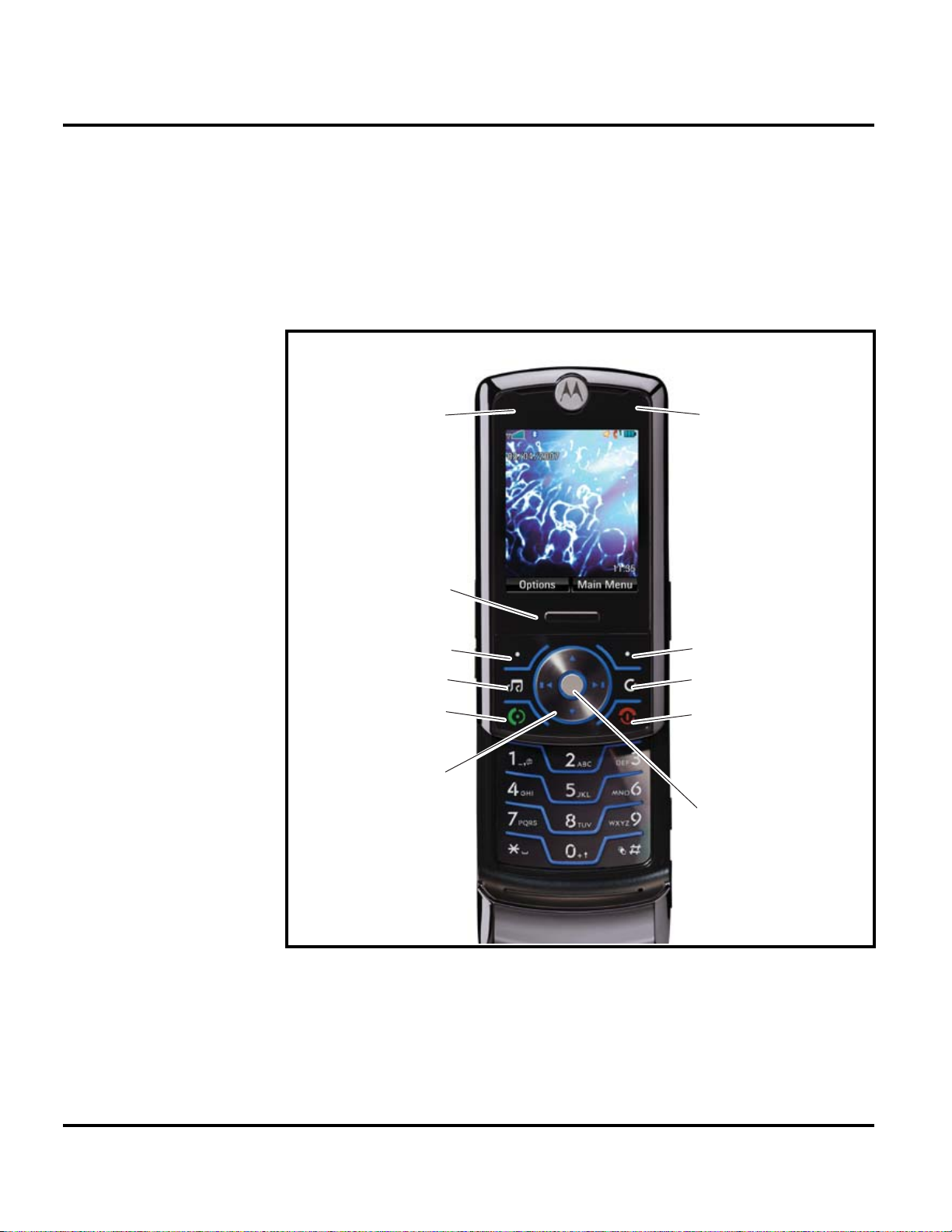
Controls, Indicators, and Input / Output (I/O) Connections
The Z6 telephone’s controls are located on the sides of the device and on the keypad.
Indicators, in the form of icons, are displayed on the LCD. Z6 phones have an audible
alert transducer on the top and I/O connectors, consisting of a headset jack and an
accessory port, located on the top and bottom of the phone. See Figure 1.
Charge Indicator Light
Push Bar
Push down to close slider.
Left Soft Key
Music Key
Send Key
Make & answer calls.
Navigation Key
Scroll up, down, left, or right.
Bluetooth Indicator Light
Right Soft Key
Clear/Back Key
Power/End Key
Turn on/off, hang up, exit menus.
Center Key
Open main menu & select menu item
0701101o
Figure 1. Controls, indicators, and I/O
“Soft keys” refer to non-labeled keys that correspond to text options displayed on
the screen. The left and right soft keys perform the function shown in the corners
of the display. The right key will usually select an option whereas the left key will
usually exit a function or return to a previous screen.
The center key opens the initial menu structure, or allows access to a submenu.
12 March 13, 2007 6809506A96-O
Page 13
Level 1 and 2 Service Manual General Operation
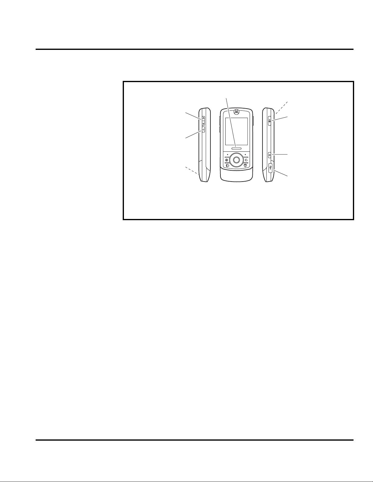
The Volume Keys, Smart key, Voice command key, and Camera key controls are
located on the sides of the Z6 (see Figure 2).
Color Display
Push Bar
Push up to open slider.
Volume Keys
Set ring volume when
slider is closed.
Smart Key *
Select menu items.
Handsfree Speaker
(on back of phone)
* This key functions as the PTT key when push to talk
service is available on your phone.
Camera Lens & High-Intensity
LED Camera Light
(on back of phone)
Voice Command Key
Use voice commands to make
calls & perform basic phone
functions.
Camera Key
Activate camera & take photos.
Mini-USB Port
Insert battery charger
& phone accessories.
060951a
Figure 2. Controls, indicators, and I/O (Side Views)
The Z6 wireless phone features a 262K color Thin Film Transistor (TFT) 176 x 220
pixel display.
Display animation makes the phone’s menus move smoothly as the user scrolls up
and down.Display
6809506A96-O March 13, 2007 13
Page 14
General Operation Z6
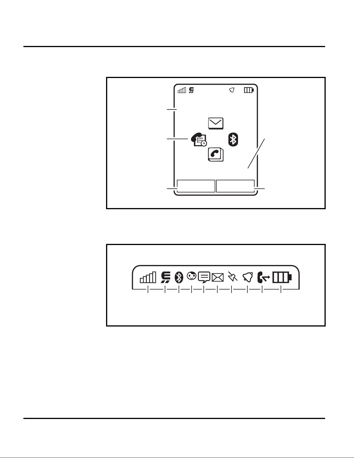
The home screen appears when you turn on the phone.The home screen may look
different, depending on the service provider.
Service Provider
Date
10/15/2008
Feature Icons
Left Soft Key
Label
Figure 3. Controls, indicators, and I/O (Side Views)
Figure 4 shows some common icons displayed on the LCD.
210613 9
Options Main Menu
45 7
10:10AM
8
Clock
Right Soft Key
Label
061789o
061790o
Figure 4. Icon Indicators
Whether a phone displays all indicators depends on the programming and services
➧
to which the user subscribes.
1. Signal Strength Indicator – Vertical bars show the strength of the wireless
0
network connection. You can’t make or receive calls when
roam indicator
your home network.
14 March 13, 2007 6809506A96-O
1
shows when your phone is seeking or using a network outside
or / shows. The
Page 15

Level 1 and 2 Service Manual General Operation
2. EDGE/GPRS Indicator – Shows when your phone is using a high-speed
Enhanced Data for GSM Evolution (EDGE) or General Packet Radio
Service (GPRS) network connection. Indicators can include:
= EDGE
,
connection
5
= EDGE data
transfer
4
= EDGE secure
data transfer
6
= EDGE
unsecure data
transfer
3. Bluetooth™ Indicator – Shows when your phone is connected with another
Bluetooth device.
4. Messaging Presence Indicator – Shows your instant messaging (IM)
status. Indicators can include:
B
= online
C
= busy
D
= invisible to IM
>
= GPRS
connection
<
= GPRS data
transfer
8
= GPRS secure
data transfer
9
= GPRS
unsecure data
transfer
E
= offline
F
= discrete
5. IM Indicator – Shows when you receive a new IM message.
6. Message Indicator – Shows when you receive a new message. Indicators
can include:
]
= text or voice
message
7. Location Indicator – Shows your phone’s location information status.
Indicators can include:
J
= location on
L
= acquiring
location
I
= location
unknown
8. Profile Indicator – Shows the alert profile setting.
)
= ring only
S
= vibrate only
O
= silent
9. Active Line Indicator – Shows X to indicate an active call, or Y to
indicate when call forwarding is on. Indicators for dual-line-enabled SIM
cards can include:
V
= line 1 active
Z
= line 1 call
forward on
[
= email
message
K
= location off
M
= location fixed
N
= ring and
vibrate
(
= vibrate then
ring
W
= line 2 active
a
= line 2 call
forward on
6809506A96-O March 13, 2007 15
Page 16

General Operation Z6
10. Battery Level Indicator – Vertical bars show the battery charge level.
Recharge the battery when your phone shows Low Battery.
Alert Settings
Z6 telephones include up to 32 preset alert tones and vibrations that can be applied
to all alert events at the same time.
Pressing either volume key will mute the alert.
➧
Battery Function
Battery Gauge
The telephone displays a battery level indicator icon in the idle screen to indicate
the battery charge level. The gauge shows four levels: 100%, 66%, 33%, and Low
Battery.
➧
G
Battery Removal
Removing the battery causes the device to immediately shut down and any pending
work (for example, partially entered phone book entries or outgoing messages) is
lost.
To ensure proper memory retention, turn OFF the phone before removing the
battery. Immediately replace the old battery with a fresh battery.
If the battery is removed while receiving a message, the message will be lost.
16 March 13, 2007 6809506A96-O
Page 17

1 and 2
Level 1 and 2 Service Manual Tools and Test Equipment
Z6
6809506A96-O
Tools and Test Equipment
The following table lists tools and test equipment recommended for disassembly
and reassembly of Z6 telephones. Use either the listed items or equivalents.
Table 1. General Test Equipment and Tools
Part Number
RSX4043-A Torque Driver Used to remove and replace screws
1
Description Application
—
See Table 7 Rapid Charger
0180386A82
6680388B67
6680388B01 Tweezers, plastic Used during assembly/disassembly
0-00-00-40841
1. To order in North America, contact Motorola Aftermarket and Accessories Division (AAD) at (800) 422-4210 or
FAX (800) 622-6210; Internationally, AAD can be reached by calling (847) 538-8023 or faxing (847) 576-3023.
2. Available from AMS Software & Elektronik GmbH, c/o Holger Grube, Lise-Meitner-Straße 9 D-24941, Flensburg
Tel.: +49-461-90398-0 Fax: +49-461-90398-50
3. Not available from Motorola. To order, contact Hewlett Packard at (800) 452-4844.
2
Torque Driver Bit T-5, Apex 440-6I Torx
or equivalent
Antistatic Mat Kit (includes 66-80387A95
antistatic mat, 66-80334B36 ground
cord, and 42-80385A59 wrist band)
Disassembly tool, plastic with flat and
pointed ends (manual opening tool)
Tweezers, metal Used during assembly/disassembly
Flex connector removal tool Used for Flip and Vibrator Flex removal
Used with torque driver
Used to charge battery and to power
device
Provides protection from damage to
device caused by electrostatic discharge
(ESD)
Used during assembly/disassembly of
device
6809506A96-O March 13, 2007 17
Page 18

Disassembly Z6
Disassembly
The procedures in this section provide instructions for the disassembly of Z6
telephones. Tools and equipment used for the phone are listed in Table 1, preceding.
Many of the integrated devices used in this equipment are vulnerable to damage
G
G
Removing and Replacing the Battery Cover and Battery
E
from electrostatic discharge (ESD). Ensure adequate static protection is in place
when handling, shipping, and servicing the internal components of this equipment.
Avoid stressing the plastic in any way to avoid damage to either the plastic or
internal components.
All batteries can cause property damage and/or bodily injury, such as burns if a
conductive material, such as jewelry, keys, or beaded chains touch exposed terminals. The conductive material may complete an electrical circuit (short circuit) and
become quite hot. Exercise care in handling any charged battery, particularly when
placing it inside a pocket, purse, or other container with metal objects.
1. Ensure the phone is turned off.
2. Press in and hold the battery door latch, as shown in Figure 5.
Battery Latch
Figure 5. Removing the Battery Door
Battery Door
060494o
3. Lift the battery cover up and over the battery, and lift it off the phone.
18 March 13, 2007 6809506A96-O
Page 19

Level 1 and 2 Service Manual Disassembly
4. Lift up the side edge of the battery first, then lift it completely out of the battery
compartment. See Figure 6.
Battery
061664o
Figure 6. Removing the battery
E
G
There is a danger of explosion if the Lithium Ion battery is replaced incorrectly.
Replace only with the same type of battery or equivalent as recommended by the
battery manufacturer. Dispose of used batteries according to the manufacturer’s
instructions.
5. To replace, align the battery with the battery compartment so the contacts on
the battery match the battery contacts in the phone.
6. Insert the side edge of the battery into the battery compartment, with the
contacts facing downward.
7. Insert the opposite edge of the battery into the battery compartment.
8. Lower the battery cover onto the phone, and press down slightly on the cover
to engage the battery latch.
Do not use the extended battery cover when using a standard battery. The battery
could separate from the contacts in the battery compartment resulting in a loss of
power.
6809506A96-O March 13, 2007 19
Page 20

Disassembly Z6
Removing and Replacing the Memory Card
1. Remove the battery cover as described in the procedures.
2. Slide the Trans Flash memory card out of its socket to release as shown in
Figure 7.
➧
The battery does not need to be removed to access the memory module.
Memory card
061665o
Figure 7. Removing the Memory Card
3. To replace, slide the memory card into its slot. The memory card can be
correctly inserted only one way.
4. Replace the battery cover.
20 March 13, 2007 6809506A96-O
Page 21

Level 1 and 2 Service Manual Disassembly
Removing and Replacing the Subscriber Identity Module (SIM)
1. Remove the battery door and battery as described in the procedures.
2. Slide the SIM out of the slot as indicated by the arrow (see Figure 8).
3. Carefully remove the SIM from the phone.
SIM
061666o
Figure 8. Removing the SIM
4. To replace, slide the SIM into the holder, ensuring the notched corner of the
SIM aligns with the notch molded into the holder.
5. Replace the battery and battery door as described in the procedures.
6809506A96-O March 13, 2007 21
Page 22

Disassembly Z6
Removing and Replacing the Rear Housing
This product contains static-sensitive devices. Use anti-static handling procedures
G
G
to prevent electrostatic discharge (ESD) and component damage.
1. Remove the battery cover, battery, and SIM as described in the procedures.
In addition to 4 screws, the rear housing assembly is fastened with plastic latches.
These are fragile and should be released with care.
2. Using a Torx driver with a T-5 bit, remove the 6 screws along the sides of the
rear housing. Retain the screws for reassembly. See Figure 9.
Housing screws
Housing screws
051855o
Figure 9. Removing the Rear Housing Screws
3. Lift up the rear housing as shown in fig 1 and insert the flat end of the
disassembly tool into the opening.
22 March 13, 2007 6809506A96-O
Page 23

Level 1 and 2 Service Manual Disassembly
4. Slide the black stick along the housing edge as shown in Fig 9 to disengage the
snaps.
Disassembly tool
Rear Housing
061670a
Figure 10. Removing the Rear Housing
5. Pay special attention to the snaps at the bottom near the corners. Snaps must
be pushed in to disengage.
Rear Housing
Rear Housing
Snaps
061670a
Figure 11. Removing the Rear Housing
6809506A96-O March 13, 2007 23
Page 24

Disassembly Z6
6. When all the snaps are disengaged, carefully lift the rear housing straight up
and away from the phone.
7. To replace, carefully align the rear housing to the phone, then press the front
and rear housings together until the catches snap into place.
8. Replace the 6 rear housing screws and tighten with a T5 driver to a final torque
setting of 16 Ncm (1.5 lbf in). Do not over tighten.
9. Replace the SIM, battery, and battery cover as described in the procedures.
24 March 13, 2007 6809506A96-O
Page 25

Level 1 and 2 Service Manual Disassembly
Removing the Rear Housing Speaker Cap
1. Remove the battery cover, battery, SIM and rear housing as described in the
procedures.
2. If it is necessary to replace the speaker cap, use the disassembly tool or
tweezers to remove the speaker cap from the rear housing.
Speaker cap
070373o
Figure 12. Removing the Speaker Cap
3. Remove any remaining adhesive residue from the rear housing. Discard the
speaker cap. Do not reuse.
4. To replace, expose the adhesive surface on the new speaker cap.
5. Press the speaker cap onto the rear housing.
6. Replace the SIM, battery, and battery cover as described in the procedures.
6809506A96-O March 13, 2007 25
Page 26

Disassembly Z6
Removing the Daughter Board Assembly
1. Remove the battery cover, battery, SIM, antenna, rear housing as described in
the procedures.
2. Remove the acoustic gasket with the tweezers. Set the gasket aside for reassembly unless damaged (see Figure 13).
Acoustic gasket
Daughter board
061690o
Figure 13. Removing the Acoustic Gasket
3. Insert the disassembly tool under the daughter board and rotate it to unseat
the daughter board connector from the transceiver board assembly.
Daughter board
Daughter board
061693o
Figure 14. Removing the Daughter Board Assembly
26 March 13, 2007 6809506A96-O
Page 27

Level 1 and 2 Service Manual Disassembly
Removing and Replacing the Transceiver Board Assembly
This product contains static-sensitive devices. Use anti-static handling procedures
G
G
to prevent electrostatic discharge (ESD) and component damage.
1. Remove the battery cover, battery, SIM, antenna, rear housing as described in
the procedures.
The flexible printed cable (FPC) (flex) is easily damaged. Exercise extreme care when
handling.
2. Carefully slide the end of the disassembly tool under the flex connector and
rotate the tool slightly to lift the connector from its socket on the transceiver
board. See Figure 15. Pay special attention to the electrical components around
the connector. Do not touch any components with the black stick.
HydraFlex connector
061702o
Figure 15. Disconnecting the Flex From the Transceiver Board
6809506A96-O March 13, 2007 27
Page 28

Disassembly Z6
Hydraflex connector
12a
Figure 16. Disconnecting the Hydraflex Connector From the Transceiver Board
3. Carefully slide the end of the disassembly tool under the camera flex connector
and rotate the tool slightly to lift the connector from its socket on the
transceiver board (see Figure 17).
Camera connector
Figure 17. Removing the Camera Connector
061706o
The flexible printed cable (FPC) (flex) is easily damaged. Exercise extreme care when
G
28 March 13, 2007 6809506A96-O
handling.
Page 29

Level 1 and 2 Service Manual Disassembly
4. Carefully lift the EMU connector side of the transceiver board out of the front
housing. Lift the PC board out of the phone (see Figure 18).
Tr ansceiver PC board
061708o
Figure 18. Removing the Transceiver PC Board Assembly
G
5. Carefully use the plastic tweezers to lift the camera assembly and side keys
from the phone (see Figure 19).
The flexible printed cable (FPC) (flex) is easily damaged. Exercise extreme care when
handling.
Plastic tweezers
Camera assembly
Figure 19. Removing the Camera Assembly
Volume/Smart keys
Camera key
061709o
6809506A96-O March 13, 2007 29
Page 30

Disassembly Z6
6. To replace, place the camera assembly into the housing. Ensure the external
side key switchdomes on both sides of the phone are correctly inserted behind
the keys.
7. Insert the transceiver board assembly into the front housing with the display
flex and the camera assembly flex connector on top of the transceiver PC board
assembly.
Be sure the volume/smart buttons and voice button are correctly positioned in
relation to the corresponding switches on the transceiver board. Verify operation of
➧
the buttons after replacing the transceiver board and rear chassis assembly.
8. Insert the camera flex and display flex connectors squarely into their mating
connectors on the transceiver board and press gently but firmly until they snap
into place.
9. Replace the daughterboard assembly, rear housing, antenna, SIM, battery, and
battery cover as described in the procedures.
30 March 13, 2007 6809506A96-O
Page 31

Level 1 and 2 Service Manual Disassembly
Removing and Replacing the Keypad
1. Remove battery cover, battery, SIM, antenna, rear housing, daughter board
assembly, and transceiver board assembly as described in the procedures.
2. Using the plastic tweezers, lift the keypad assembly, away from the front
housing assembly (see Figure 20).
061701o
Figure 20. Removing the Keypad
3. To replace, carefully set the keypad assembly into the front housing assembly.
Ensure the volume/smart key keypads will contact the switchdome assembly
on the transceiver board when installed.
4. Insert the keypad into the front housing, use the guide pins molded into the
front housing to ensure the keypad is placed correctly in the front housing.
5. Replace the transceiver board assembly, daughter board assembly, rear
housing assembly, antenna, SIM, battery, and battery cover as described in
the procedures.
6809506A96-O March 13, 2007 31
Page 32

Disassembly Z6
Removing and Replacing the Antenna
1. Remove battery cover, battery, SIM, rear housing, daughter board assembly,
transceiver board assembly, and keypad as described in the procedures.
2. Insert the disassembly tool under the antenna assembly and rotate the
disassembly tool to raise the antenna assembly out of the front housing.
Disassembly tool
Antenna assembly
061758o
Figure 21. Removing the Antenna
3. To replace, align the antenna to the front housing.
4. Gently lower the antenna assembly into the front housing until the antenna
assembly snaps engage the latches in the front housing.
5. Replace the keypad, transceiver board assembly, keypad, daughter board
assembly, rear housing, SIM, battery, and battery cover as described in the
procedures.
32 March 13, 2007 6809506A96-O
Page 33

Level 1 and 2 Service Manual Disassembly
Removing the Front Housing
1. Remove battery cover, battery, SIM, rear housing, daughter board assembly,
transceiver board assembly, keypad, and the antenna as described in the
procedures.
G
The hydraflex can be easily damaged. Use extreme caution during this next step.
2. Use the disassembly tool to disconnect the front housing snaps from the metal
guide.
Disassembly tool
Chassis
assembly
metal
guide
Front housing snap locations
061758o
Figure 22. Removing the Front Housing Snaps
6809506A96-O March 13, 2007 33
Page 34

Disassembly Z6
3. After the snaps are disengaged, lift up the front housing straight upward.
Route the hydraflex carefully through the opening in the front housing without
damaging the flex.
Front housing
Hydraflex
061760o
Figure 23. Removing the Front Housing
4. To replace, carefully thread the hydraflex through the opening in the front
housing.
5. Lower the front housing onto the chassis assembly metal guide.
6. Press down on the front housing to engage the two housing snaps to the chassis
metal guide.
7. Replace the keypad, transceiver board assembly, daughter board assembly,
rear housing, SIM, battery, and battery cover as described in the procedures.
34 March 13, 2007 6809506A96-O
Page 35

Level 1 and 2 Service Manual Disassembly
Removing the Slider Assembly
1. Remove battery cover, battery, SIM, rear housing, daughter board assembly,
transceiver board assembly, keypad, and front housing as described in the
procedures.
G
The hydraflex can be easily damaged. Use extreme caution during this next step.
2. Use the T5 driver to remove the 2 slider screws from the slider assembly.
Slider assembly screw
Slider assembly screw
061769o
Figure 24. Removing the Slider Assembly Screws
6809506A96-O March 13, 2007 35
Page 36

Disassembly Z6
3. Use the disassembly tool to lift only the top end of the slider inner assembly
out of the slider outer assembly. Leave the bottom end attached.
Disassembly tool
Slider inner assembly
Figure 25. Removing the Slider Assembly Screws
061770o
36 March 13, 2007 6809506A96-O
Page 37

Level 1 and 2 Service Manual Disassembly
4. Rotate the slider inner assembly upward, to expose the keypad flex connector
which is still attached to the slider outer assembly.
Keypad flex
connector
Slider
“mag” assembly
061771a
Figure 26. Removing the Keypad Flex Connector
5. Use the disassembly tool to unseat the keypad flex connector. Ensure the
electrical components around the connector are not damaged.
6. Remove the slider front housing from the slider "mag" assembly.
7. To replace, align the slider front housing to the slider "mag" assembly.
8. Insert the keypad end of the slider front housing to the slider mag assembly.
9. Connect the keypad flex connector to the slider "mag" assembly.
10. Lower the top end of the slider inner assembly onto the slider "mag" assembly.
11. Insert and tighten the 2 T5 slider assembly screws. Tighten screws to 1.1 +/-
0.1 in-lbf. Do not overtighten.
12. Replace the front housing, transceiver board assembly, daughter board
assembly, rear housing, SIM, battery, and battery as described in the
procedures.
6809506A96-O March 13, 2007 37
Page 38

Disassembly Z6
Removing and Replacing the Display Module
1. Remove the battery cover, battery, SIM, rear housing, daughter board
assembly, transceiver board assembly, keypad, front housing, and slider
assembly as described in the procedures.
2. Use the disassembly tool to unlock the zero insertion force (ZIF) connector.
ZIF connector
062091a
Figure 27. Unlocking the Display Module ZIF Connector
3. Use the plastic tweezers to lift up the opposite end of the display module.
4. Carefully remove the display module out of the ZIF connector and away from
the slider assembly.
5. To replace, align the display module to the slider assembly.
6. Lower the display module into the slider assembly.
7. Insert the display module connector into the ZIF socket.
8. Use the pointed end of the disassembly tool to close and lock the ZIF connector.
9. Replace the slider assembly, front housing, keypad, transceiver board
assembly, daughter board assembly, rear housing, SIM, battery, and battery
cover as described in the procedures.
38 March 13, 2007 6809506A96-O
Page 39

Level 1 and 2 Service Manual Disassembly
Removing and Replacing the Keypad Mylar
It is mandatory that the following special tools must be used when
following this procedure:
G
Z6 EL Alignment- and Press Tool - part number 0-00-00-40852
Generic Press Fixture - part number 19501980 Available at the AMS Online-shop
62.214.1.200 (for access please contact your local Motorola contact)
The Z6 EL alignment and press tool must be used for this replacement procedure.
070270o
Figure 28. Z6 EL Alignment and Press Tool
6809506A96-O March 13, 2007 39
Page 40

Disassembly Z6
1. Remove the keypad mylar with the plastic tweezers, as shown.
Tw ee ze r s
Mylar
PCB
Figure 29. Removing the Keypad Mylar
2. To replace the keypad mylar, use the Z3 EL Alignment and Press tool.
070271o
40 March 13, 2007 6809506A96-O
Page 41

Level 1 and 2 Service Manual Disassembly
3. Peel off the adhesive liner from the bottom side of the keypad mylar. Place the
keypad into the fixture. Align the keypad using the fixture alignment pins.
Alignment pin
Alignment pin
Figure 30. Keypad Mylar Alignment
070272o
6809506A96-O March 13, 2007 41
Page 42

Disassembly Z6
4. Clean the mylar area on the main PCB, and then place it on top of the keypad
mylar using the fixture alignment pins.
PCB (shields
facing up)
Figure 31. PCB Alignment
070273o
42 March 13, 2007 6809506A96-O
Page 43

Level 1 and 2 Service Manual Disassembly
5. Close the fixture for 15 seconds.
070274o
Figure 32. El Mylar Press Fixture Closed
6. Open the fixture and check the assembly for correct positioning of the mylar
on the PCB
6809506A96-O March 13, 2007 43
Page 44

Subscriber Identity Module (SIM) and Identification Z6
Subscriber Identity Module (SIM) and Identification
SIM Card
A SIM is required to access the existing local GSM network, or remote networks
when traveling (if a roaming agreement has been made with the provider).
The SIM contains:
• All the data necessary to access GSM services.
• The ability to store user information, such as phone numbers.
• All information required by the network provider to provide access to the network.
Personality Transfer
A personality transfer is required when a phone is express exchanged or when the
main board is replaced. Personality transfers reproduce the customer's original
personalized details, such as menu and stored memory, such as phone books, or
even just program a unit with basic user information such as language selection.
Z6 telephones use Mobile Phone Tools software to effect a personality transfer.
Identification
Each Motorola GSM device is labeled with a variety of identifying numbers. The
following information describes the current identifying labels.
Mechanical Serial Number (MSN)
The Mechanical Serial Number (MSN) is an individual unit identity number and
remains with the unit throughout the life of the unit.
The MSN can be used to log and track a unit on Motorola's Service Center Database.
The MSN is divided into 4 sections as shown in Figure 33.
MSN 10 Digits
3 Digits 1 Digit 2 Digits 4 Digits
APC DC DC SNR
Account Product Code
i.e. StarTAC Phone130
TM
Figure 33. MSN Label breakdown
Distribution Center
i.e. Easter Inch
Date Code: Year and
Month of Shipment
Unit's individual serial
number
000807a
44 March 13, 2007 6809506A96-O
Page 45

Level 1 and 2 Service Manual Subscriber Identity Module (SIM) and Identification
International Mobile Station Equipment Identity (IMEI)
The International Mobile station Equipment Identity (IMEI) number is an
individual number unique to the PCB and is stored within the unit's memory.
The IMEI uniquely identifies an individual mobile station and thereby provides a
means for controlling access to GSM networks based on mobile station types or
individual units. The full IMEI structure is listed in Table 2.
Table 2. IMEI Number Breakdown
TAC Serial Number Check Digit
NNXXXXXX ZZZZZZ A
Where
TAC Type Allocation Code, formerly known as Type Approval Code
NN Reporting body identifier
XXXXXX Type Identifier
ZZZZZZ Individual unit serial number
A Phase 1 = 0.
Phase 2 = check digit defined as a function of all other IMEI digits
Other label number configurations present are:
• TRANSCEIVER NUMBER: Identifies the product type. Normally the SWF
number. (i.e. V100).
• PACKAGE NUMBER: Identifies the equipment type, mode, and language in
which the product is shipped.
6809506A96-O March 13, 2007 45
Page 46

Troubleshooting Z6
Troubleshooting
46 March 13, 2007 6809506A96-O
Page 47

Level 1 and 2 Service Manual Troubleshooting
Troubleshooting Chart
Table 3. Level 1 and 2 Troubleshooting Chart
SYMPTOM PROBABLE CAUSE VERIFICATION AND REMEDY
1. Telephone will not turn on or stay on. a) Battery either discharged or
2. Telephone exhibits poor reception or
erratic operation, such as calls frequently
dropping or weak or distorted audio.
3. Display is erratic, or provides partial or
no display.
4. Incoming call alert transducer audio
distorted or volume is too low.
5. Telephone transmit audio is weak.
(usually indicated by called parties
complaining of difficulty in hearing voice).
defective.
b) Battery connectors open or
misaligned.
c) Transceiver board assembly
defective.
a) Antenna assembly defective. Check to make sure that the antenna pin is
b) Transceiver board assembly
defective.
a) Transceiver board connections
faulty.
b) Flip assembly defective. Temporarily replace the flip assembly with a
c) Transceiver board assembly
defective.
a) Faulty alert transducer Replace with a known good alert transducer.
b) Faulty transceiver board assembly. Refer service to authorized Level 3 service
a) Microphone connections to the
transceiver board assembly defective.
b) Microphone defective. Gain access to microphone. Disconnect and
c) Transceiver board assembly
defective.
Measure battery voltage across a 50 ohm (>1
Watt) load. If the battery voltage is <3.25 Vdc,
recharge the battery using the appropriate
battery charger. If the battery will not recharge,
replace the battery. If battery is not at fault,
proceed to b.
Visually inspect the battery connectors on both
the battery and the telephone. Realign and, if
necessary, either replace the battery or refer to
a Level 3 Service Center for the battery
connector replacement. If battery connectors
are not at fault, proceed to c.
Refer service to authorized Level 3 service
center for replacement.
properly connected to the transceiver board
assembly. If connected properly, substitute a
known good antenna. If the fault is still present,
proceed to b.
Refer service to authorized Level 3 service
center for replacement.
Remove rear chassis assembly from unit, check
general
condition of flexible printed cable (flex). If the flex
is good, check that the flex connector is fully
pressed down. If not, check connector to
transceiver board connections. If faulty
connector, replace the transceiver board
assembly. If connector is not at fault, proceed to
b.
known good assembly. If fault has been cleared,
reassemble with the new flip assembly. If fault
not cleared, proceed to c.
Refer service to authorized Level 3 service
center for replacement.
Verify that the fault has been cleared and
reassemble the unit with the new alert
transducer. If fault not cleared, proceed to b.
center for replacement.
Gain access to the microphone as described in
the procedures. Check connections. If connector
is faulty proceed to c; if the connector is not at
fault, proceed to b.
substitute a known good microphone. Place a
call and verify improvement in transmit signal as
heard by called party. If good, reassemble with
new microphone. If microphone is not at fault,
reinstall original microphone and proceed to c.
Refer service to authorized Level 3 service
center for replacement.
6809506A96-O March 13, 2007 47
Page 48

Troubleshooting Z6
Table 3. Level 1 and 2 Troubleshooting Chart (Continued)
SYMPTOM PROBABLE CAUSE VERIFICATION AND REMEDY
6. Receive audio from earpiece speaker is
weak or distor ted.
7. Telephone will not recognize or accept
SIM.
8. Phone does not sense when flip is
opened or closed (usually indicated by
inability to answer incoming calls by
opening the flip, or inability to make
outgoing calls).
10. Internal Charger not working. Faulty charger circuit on transceiver
11. Real Time Clock resetting when
standard battery is removed.
a) Connections to or from transceiver
board assembly defective.
b) Slider assembly defective. Temporarily replace the slider assembly with a
c) Antenna assembly defective. Check to make sure the antenna is installed
d) Transceiver board assembly
defective.
a) SIM defective. Check the SIM contacts for dirt. Clean if
b) Transceiver board assembly
defective.
a) Transceiver board assembly
defective.
board assembly.
Lithium button cell in the display board
may be depleted.
Gain access to the transceiver board assembly
as described in the procedures. Check flex and
the flex connector from the slider assembly to
the transceiver board assembly. If flex is at fault,
replace slider assembly. If flex connector is at
fault, proceed to d. If connection is not at fault,
proceed to b.
known good assembly. If fault has been cleared,
reassemble with the new slider assembly. If fault
not cleared, proceed to c.
correctly. If the antenna is installed correctly,
substitute a known good antenna assembly. If
this does not clear the fault, reinstall the original
antenna assembly and proceed to d.
Refer service to authorized Level 3 service
center for replacement.
necessary and check if fault has been cleared. If
the contacts are clean, insert a known good SIM
into the telephone. Power up the unit and
confirm that the SIM has been accepted. If the
fault no longer exists, replace the defective SIM.
If the SIM is not at fault, proceed to b.
Send unit to authorized level 3 service center for
transceiver PC board replacement.
Refer service to authorized Level 3 service
center for replacement.
Refer service to authorized Level 3 service
center for replacement.
Refer service to a Level 3 service center for
replacement.
Programming: Software Upgrade and Flexing
Contact your local technical support engineer for information about equipment and
procedures for flashing and flexing.
Part Numbers
The following information is provided as a reference for the parts associated with
Z6 telephones.
48 March 13, 2007 6809506A96-O
Page 49

Level 1 and 2 Service Manual Troubleshooting
1
2
3
4
5
7
9
13
14
15
27
24
24
22
17
19
23
25
18
21
28
20
29
34
31
32
33
30
16
10
11
12
6
8
Exploded View Diagram
14
16
15
17
19
23
25
28
27
20
24
18
21
22
24
30
29
10
11
12
32
31
33
34
Figure 34. Exploded View Diagram (Sheet 1)
13
061699o
6809506A96-O March 13, 2007 49
Page 50

Troubleshooting Z6
48
49
35
36
38
37
39
40
41
46
44
45
50
51
55
58
57
42
43
46
46
46
46
53
52
54
47
35
53
54
46
46
52
57
48
49
51
58
50
55
46
47
43
37
39
44
45
36
38
42
46
46
Figure 35. Exploded View Diagram (Sheet 2)
41
40
061734o
50 March 13, 2007 6809506A96-O
Page 51

Level 1 and 2 Service Manual Troubleshooting
Parts List
Part numbers are provided only as a reference. Contact your local Motorola parts
organization for current part number information.
Table 4. Parts List
Item Motorola Part No. Description
1 0171646D Slide assembly
2 3871530D01 Main keypad
3 8471322D01 Main board assembly
4 4071686D01 EL panel, dome array assembly
5 3287434Y01 Microphone mesh gasket
6 01714220E01 Daughter board assembly
7 0171697D Base back housing assembly
8 3271526D01 Rear side acoustic seal
9 0371117F01 Machined shoulder screws
10 0188392P01 Battery, 750 mAh, SC4
11 0387791L09 Thread forming screws
12 1571524D Battery Cover
13 0171893D Rear Cap Assembly
14 6171490D01 Main glass lens
15 0171696D Slide outer housing assembly
16 3871529D01 Slide keypad assembly
17 0171652D01 Slide keypad flex assembly
18 3271735E01 LED gasket
19 4171200F01 Slide bottom ground spring
20 7271696E01 Display module assembly
21 1171772E01 Earpiece speaker gasket
22 0171651D01 Hydra flex assembly
23 0371235E04 Magnesium forming screws
24 0371064E04 Slide standard head screws
25 5970377C03 Hall effect magnet
26 1171178F01 Hydra flex adhesive
27 0171647D01 Slide inner housing assembly
28 1571527D Top cap housing
29 0171648D Base front housing assembly
30 0171756D02 Daughter flex camera/key assembly
31 3587505Y01 Mic screen
32 3871523D03 Side camera button
33 0171650D01 Antenna spacer assembly
34 3271525D01 Front side acoustic seal
35 3271489D01 Earpiece speaker gasket grill cloth
36 3271488D01 Display dust gasket
37 7571867D01 Flex poron
38 0171417E Slide outer medallion assembly
39 0771222F01 Antenna connector support
40 1571519D01 Antenna spacer housing
41 8571611D01 Main antenna
42 2771496D01 Guide metal chassis assembly
43 4371944D01 Guide metal delrin collar
44 5571586D01 Slider mechanism spring
45 4371826E01 Slide inner bushing
46 4671486D01 Slide rail
47 1571485D01 Slide inner housing
48 4271764E01 Waffle ground clip
49 8471915D01 Daughter board assembly
6809506A96-O March 13, 2007 51
Page 52

Troubleshooting Z6
Table 4. Parts List (Continued)
Item Motorola Part No. Description
50 7571045E01 Camera Gasket
51 7571046E01 Camera connector poron
52 5571518D01 Door latch
53 5071508D03 Polyphonic speaker, 14x20
54 1171109E01 Speaker adhesive
55 1571505D Base back housing
56 5471536C01 Water detect label, 3mm diameter
57 1571495D01 USB door
58 6171503D01 Camera lens
59 4171340E02 Battery door ground spring, right
60 4171340E01 Battery door ground spring, left
To order parts you may use the following link:
https://wissc.motorola.com/wissc_root/main/BrowserOK.html
(Password is Required)
For information on ordering parts please contact EMEA at + 49 461 803 1404.
E
There is a danger of explosion if the Lithium Ion battery pack is replaced incorrectly.
Replace only with the same type of battery or equivalent as recommended by the
battery manufacturer. Dispose of used batteries according to the manufacturer’s
instructions.
52 March 13, 2007 6809506A96-O
Page 53

1 and 2
Index
Level 1 and 2 Service Manual Index
Z6
6809506A96-O
A
active line indicator 15
alert settings
alert style profiles
Antenna, removing and replacing
16
15
32
B
battery
function
gauge
removing
battery housing
removing
battery indicator
Bluetooth indicator
16
16
18
18
16
15
C
call forward indicator 15
Canadian Interference-Causing Equipment regulations
changes
product
conventions
copyrights
computer software
4
6
5
D
daughter board assembly, removing and replacing 26
disassembly
display
Display module, removing and replacing
13
18
38
E
EDGE indicator 15
exploded view diagram
exploded view parts list
49
51
F
FCC rules 4
features
SIM Toolkit
text entry
voice recognition
features, product
Front Housing, removing and replacing
11
11
11
10
33
G
GPRS indicator 15
H
home screen 13
I
identification 44
international mobile station equipment identity
mechanical serial number
product
IM indicators
IMEI
in-call indicator
Introduction
45
4
15
15
4
K
keypad, removing and replacing 31
L
location indicator 15
4
Low Battery message
M
memory card
removing
menu
structure diagram
message indicator
MSN
44
20
15
N
names
product
4
O
operation
controls, indicators, and I/O
operation, general
overview, product
12
10
P
parts 48
exploded view diagram
exploded view parts list
product
changes
identification
names
4
4
4
45
44
16
16
12
49
51
6809506A96-O March 13, 2007 Index-1
Page 54

Index Z6
profile indicator 15
profiles
15
R
rear housing
removing
regulatory agency compliance
removing
Antenna
battery
battery housing
daughter board assembly
Display module
Front Housing
keypad
memory card
rear housing
SIM
Slider assembly
speaker cap
transceiver board assembly
replacement parts
contact information
replacing
Antenna
battery
daughter board assembly
Display module
Front Housing
keypad
rear housing
SIM
Slider assembly
speaker cap
transceiver board assembly
21
21
22
32
16, 18
31
32
18
31
18
38
33
20
22
35
25
6
38
33
22
35
25
26
26
upon battery removal
signal strength indicator
SIM Application Toolkit
SIM card
4
SIM, removing and replacing
Slider assembly, removing and replacing
speaker cap, removing and replacing
specifications
support
44
personality transfer
replacing
customer
product
21
8
6
6
16
14
11
44
21
35
25
T
text entry 11
27
tools and test equipment
transceiver board assembly, removing and replacing
troubleshooting
46
U
user interface diagrams 16
17
27
V
voice recognition 11
W
warranty service 6
27
S
serial number
mechanical
service manual
about
revisions
scope
service policy
customer support
out of box failure
product support
service procedure
ordering replacement parts
shut down
Index-2 March 13, 2007 6809506A96-O
44
5
6
5
6
6
6
6
6
Page 55

Page 56

 Loading...