

Page 1
Motorola Solutions
WiNG 4.4
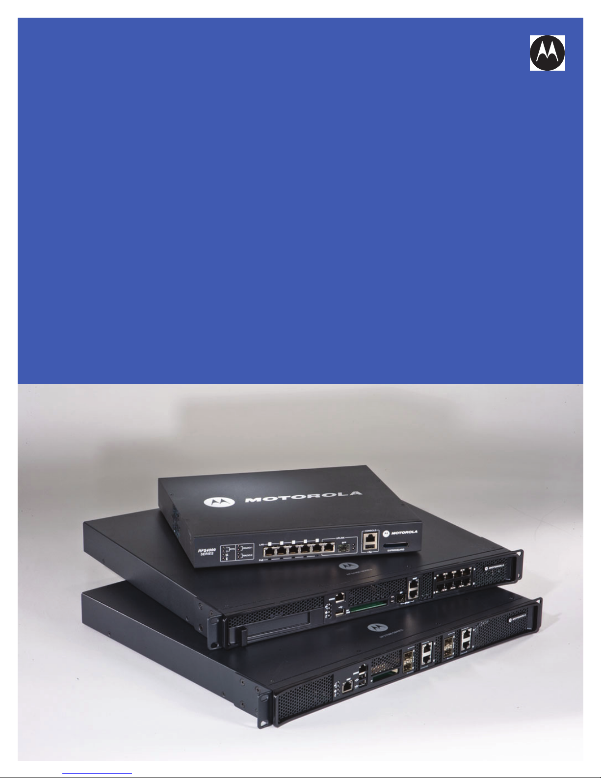
SYSTEM REFERENCE GUIDE
Page 2

Page 3

MOTOROLA SOLUTIONS WING 4.4
SYSTEM REFERENCE GUIDE
72E-157062-01
Revision A
January 2012
Page 4

ii WiNG 4.4 Switch System Reference Guide
No part of this publication may be reproduced or used in any form, or by any electrical or mechanical means,
without permission in writing from Motorola Solutions. This includes electronic or mechanical means, such as
photocopying, recording, or information storage and retrieval systems. The material in this manual is subject to
change without notice.
The software is provided strictly on an “as is” basis. All software, including firmware, furnished to the user is on
a licensed basis. Motorola Solutions grants to the user a non-transferable and non-exclusive license to use
each software or firmware program delivered hereunder (licensed program). Except as noted below, such
license may not be assigned, sublicensed, or otherwise transferred by the user without prior written consent of
Motorola Solutions. No right to copy a licensed program in whole or in part is granted, except as permitted
under copyright law. The user shall not modify, merge, or incorporate any form or portion of a licensed program
with other program material, create a derivative work from a licensed program, or use a licensed program in a
network without written permission from Motorola Solutions. The user agrees to maintain Motorola Solutions’s
copyright notice on the licensed programs delivered hereunder, and to include the same on any authorized
copies it makes, in whole or in part. The user agrees not to decompile, disassemble, decode, or reverse
engineer any licensed program delivered to the user or any portion thereof.
Motorola Solutions reserves the right to make changes to any software or product to improve reliability,
function, or design.
Motorola Solutions does not assume any product liability arising out of, or in connection with, the application or
use of any product, circuit, or application described herein.
No license is granted, either expressly or by implication, estoppel, or otherwise under any Motorola Solutions,
Inc., intellectual property rights. An implied license only exists for equipment, circuits, and subsystems
contained in Motorola Solutions products.
Page 5
Revision History
Changes to the original guide are listed below:
Change Date Description
Rev A January 2012 Manual updated to WiNG 4.4 baseline
iii
Page 6

iv WiNG 4.4 Switch System Reference Guide
Page 7

TABLE OF CONTENTS
About This Guide
Introduction.......................................................................................................................................................................................................... vii
Documentation Set ...................................................................................................................................................................................... vii
Document Conventions .............................................................................................................................................................................. viii
Notational Conventions .............................................................................................................................................................................. viii
Chapter 1, Overview
1.1 Hardware Overview .....................................................................................................................................................................................1-2
1.1.1 Physical Specifications ......................................................................................................................................................................1-2
1.2 Software Overview .......................................................................................................................................................................................1-4
1.2.1 Infrastructure Features ......................................................................................................................................................................1-4
1.2.2 Wireless Switching ...........................................................................................................................................................................1-7
1.2.3 Wired Switching ..............................................................................................................................................................................1-16
1.2.4 Management Features ...................................................................................................................................................................1-17
1.2.5 Security Features .............................................................................................................................................................................1-18
1.2.6 Supported Access Ports/Points .......................................................................................................................................................1-24
1.3 IEEE Standards Support ..............................................................................................................................................................................1-25
1.4 Standards Support ......................................................................................................................................................................................1-29
Chapter 2, Switch Web UI Access and Image Upgrades
2.1 Accessing the Switch Web UI ......................................................................................................................................................................2-2
2.1.1 Web UI Requirements .......................................................................................................................................................................2-2
2.1.2 Connecting to the Switch Web UI .....................................................................................................................................................2-2
2.2 Switch Password Recovery ..........................................................................................................................................................................2-4
2.3 Upgrading the Switch Image ........................................................................................................................................................................2-5
2.4 Auto Installation ...........................................................................................................................................................................................2-6
2.5 AP-4131 Access Point to Access Port Conversion .......................................................................................................................................2-8
Chapter 3, Switch Information
3.1 Viewing the Switch Interface .......................................................................................................................................................................3-2
3.1.1 Setting the Switch Country Code ......................................................................................................................................................3-2
3.1.2 Viewing the Switch Configuration ....................................................................................................................................................3-2
3.1.3 Switch Dashboard Details .................................................................................................................................................................3-4
Page 8

vi WiNG 4.4 Switch System Reference Guide
3.1.4 Viewing Switch Statistics ...............................................................................................................................................................3-11
3.2 Viewing Switch Port Information ...............................................................................................................................................................3-13
3.2.1 Viewing the Port Configuration .......................................................................................................................................................3-13
3.2.2 Viewing the Ports Runtime Status ..................................................................................................................................................3-16
3.2.3 Reviewing Port Statistics ................................................................................................................................................................3-17
3.2.4 Power over Ethernet (PoE) ...............................................................................................................................................................3-21
3.2.5 Editing Port PoE Settings .................................................................................................................................................................3-23
3.2.6 Configuring WAN Interface Cards ...................................................................................................................................................3-24
3.3 Viewing Switch Configurations ..................................................................................................................................................................3-26
3.3.1 Viewing the Detailed Contents of a Config File ..............................................................................................................................3-27
3.3.2 Transferring a Config File ................................................................................................................................................................3-28
3.4 Viewing Switch Firmware Information .......................................................................................................................................................3-30
3.4.1 Editing the Switch Firmware ...........................................................................................................................................................3-31
3.4.2 Enabling Global Settings for the Image Failover .............................................................................................................................3-31
3.4.3 Updating the Switch Firmware ........................................................................................................................................................3-32
3.5 Switch File Management ...........................................................................................................................................................................3-34
3.5.1 Transferring Files .............................................................................................................................................................................3-34
3.5.2 Viewing Files ...................................................................................................................................................................................3-37
3.6 Configuring Automatic Updates .................................................................................................................................................................3-39
3.7 Viewing the Switch Alarm Log ...................................................................................................................................................................3-41
3.7.1 Viewing Alarm Log Details ..............................................................................................................................................................3-42
3.8 Viewing Switch Licenses ............................................................................................................................................................................3-44
3.9 How to use the Filter Option ......................................................................................................................................................................3-46
Chapter 4, Network Setup
4.1 Displaying the Network Interface ................................................................................................................................................................4-2
4.2 Viewing Network IP Information ..................................................................................................................................................................4-4
4.2.1 Configuring DNS ................................................................................................................................................................................4-4
4.2.2 Configuring IP Forwarding .................................................................................................................................................................4-6
4.2.3 Viewing Address Resolution .............................................................................................................................................................4-8
4.3 Viewing and Configuring Layer 2 Virtual LANs ............................................................................................................................................4-9
4.3.1 Viewing and Configuring VLANs by Port ...........................................................................................................................................4-9
4.3.2 Editing the Details of an Existing VLAN by Port ..............................................................................................................................4-10
4.3.3 Viewing and Configuring Ports by VLAN .........................................................................................................................................4-11
4.4 Configuring Switch Virtual Interfaces ........................................................................................................................................................4-14
4.4.1 Configuring the Virtual Interface .....................................................................................................................................................4-14
4.4.2 Viewing Virtual Interface Statistics ................................................................................................................................................4-17
4.5 Viewing and Configuring Switch WLANs ..................................................................................................................................................4-22
4.5.1 Configuring WLANs .........................................................................................................................................................................4-22
4.5.2 Viewing WLAN Statistics ................................................................................................................................................................4-58
4.5.3 Configuring WMM ...........................................................................................................................................................................4-64
4.5.4 Configuring the NAC Inclusion List .................................................................................................................................................4-68
4.5.5 Configuring the NAC Exclusion List .................................................................................................................................................4-72
4.5.6 NAC Configuration Examples Using the Switch CLI .......................................................................................................................4-74
4.6 Viewing Associated MU Details ................................................................................................................................................................4-77
4.6.1 Viewing MU Status .........................................................................................................................................................................4-77
4.6.2 Configuring Mobile Units ................................................................................................................................................................4-81
4.6.3 Viewing MU Statistics .....................................................................................................................................................................4-82
4.6.4 Viewing MU Voice Statistics ...........................................................................................................................................................4-86
4.7 Viewing Access Port Information ...............................................................................................................................................................4-89
4.7.1 Configuring Access Port Radios ......................................................................................................................................................4-89
4.7.2 Viewing AP Statistics ....................................................................................................................................................................4-102
4.7.3 Configuring WLAN Assignment ....................................................................................................................................................4-106
4.7.4 Configuring WMM .........................................................................................................................................................................4-108
Page 9

Table of Contents vii
4.7.5 Configuring Access Point Radio Bandwidth ..................................................................................................................................4-110
4.7.6 Configuring Radio Groups for MU Load Balancing .......................................................................................................................4-111
4.7.7 Viewing Active Calls (AC) Statistics .............................................................................................................................................4-113
4.7.8 Viewing Mesh Statistics ...............................................................................................................................................................4-114
4.7.9 Smart RF ........................................................................................................................................................................................4-116
4.7.10 Voice Statistics ............................................................................................................................................................................4-125
4.8 Viewing Access Port Adoption Defaults ..................................................................................................................................................4-128
4.8.1 Configuring AP Adoption Defaults ................................................................................................................................................4-128
4.8.2 Configuring Layer 3 Access Port Adoption ....................................................................................................................................4-135
4.8.3 Configuring WLAN Assignment ....................................................................................................................................................4-135
4.8.4 Configuring WMM ........................................................................................................................................................................4-137
4.9 Configuring Access Ports ..........................................................................................................................................................................4-140
4.9.1 Viewing Adopted Access Ports .....................................................................................................................................................4-140
4.9.2 Viewing Unadopted Access Ports .................................................................................................................................................4-142
4.9.3 Access Port Configuration .............................................................................................................................................................4-143
4.9.4 Viewing Sensor Information ..........................................................................................................................................................4-146
4.9.5 Configuring Secure WiSPe ............................................................................................................................................................4-148
4.9.6 Configuring Adaptive AP Firmware ...............................................................................................................................................4-149
4.10 Multiple Spanning Tree ..........................................................................................................................................................................4-153
4.10.1 Configuring a Bridge ....................................................................................................................................................................4-153
4.10.2 Viewing and Configuring Bridge Instance Details ......................................................................................................................4-156
4.10.3 Configuring a Port ........................................................................................................................................................................4-157
4.10.4 Viewing and Configuring Port Instance Details ..........................................................................................................................4-161
4.11 IGMP Snooping .......................................................................................................................................................................................4-164
4.11.1 IGMP Snoop Configuration ..........................................................................................................................................................4-164
4.11.2 IGMP Snoop Querier Configuration .............................................................................................................................................4-165
4.12 Wired Hotspot ........................................................................................................................................................................................4-167
4.12.1 Wired Hotspot Configuration ......................................................................................................................................................4-167
Chapter 5, Switch Services
5.1 Displaying the Services Interface .................................................................................................................................................................5-2
5.2 DHCP Server Settings ...................................................................................................................................................................................5-4
5.2.1 Configuring the Switch DHCP Server ................................................................................................................................................5-5
5.2.2 Viewing the Attributes of Existing Host Pools ................................................................................................................................5-10
5.2.3 Configuring Excluded IP Address Information .................................................................................................................................5-12
5.2.4 Configuring the DHCP Server Relay ................................................................................................................................................5-13
5.2.5 Viewing DDNS Bindings ..................................................................................................................................................................5-15
5.2.6 Viewing DHCP Bindings ..................................................................................................................................................................5-15
5.2.7 Reviewing DHCP Dynamic Bindings ................................................................................................................................................5-16
5.2.8 Configuring the DHCP User Class ...................................................................................................................................................5-18
5.2.9 Configuring DHCP Pool Class ..........................................................................................................................................................5-20
5.3 Configuring Secure NTP .............................................................................................................................................................................5-23
5.3.1 Defining the SNTP Configuration ....................................................................................................................................................5-23
5.3.2 Configuring Symmetric Key .............................................................................................................................................................5-25
5.3.3 Defining a NTP Neighbor Configuration .........................................................................................................................................5-27
5.3.4 Adding an NTP Neighbor .................................................................................................................................................................5-28
5.3.5 Viewing NTP Associations ..............................................................................................................................................................5-30
5.3.6 Viewing NTP Status ........................................................................................................................................................................5-32
5.4 Configuring Switch Redundancy & Clustering ...........................................................................................................................................5-34
5.4.1 Configuring Redundancy Settings ...................................................................................................................................................5-35
5.4.2 Reviewing Redundancy Status ........................................................................................................................................................5-38
5.4.3 Configuring Redundancy Group Membership .................................................................................................................................5-42
5.4.4 Redundancy Group License Aggregation Rules ..............................................................................................................................5-45
5.4.5 Managing Clustering Using the Web UI .........................................................................................................................................5-46
Page 10

viii WiNG 4.4 Switch System Reference Guide
5.5 Layer 3 Mobility ..........................................................................................................................................................................................5-48
5.5.1 Configuring Layer 3 Mobility ...........................................................................................................................................................5-49
5.5.2 Defining the Layer 3 Peer List .........................................................................................................................................................5-51
5.5.3 Reviewing Layer 3 Peer List Statistics ............................................................................................................................................5-52
5.5.4 Reviewing Layer 3 MU Status .........................................................................................................................................................5-53
5.6 Configuring Self Healing ............................................................................................................................................................................5-54
5.6.1 Configuring Self Healing Neighbor Details .....................................................................................................................................5-55
5.7 Configuring Switch Discovery ....................................................................................................................................................................5-58
5.7.1 Configuring Discovery Profiles ........................................................................................................................................................5-58
5.7.2 Viewing Discovered Switches .........................................................................................................................................................5-60
5.8.1 RTLS Overview .................................................................................................................................................................................5-63
5.8.2 SOLE - Smart Opportunistic Location Engine ..................................................................................................................................5-64
5.8.3 Defining Site Parameters ................................................................................................................................................................5-64
5.8.4 Configuring SOLE Parameters .........................................................................................................................................................5-66
5.8.5 Configuring Aeroscout Parameters .................................................................................................................................................5-68
5.8.6 Configuring Ekahau Parameters ......................................................................................................................................................5-70
Chapter 6, Switch Security
6.1 Displaying the Main Security Interface ........................................................................................................................................................6-2
6.2 Access Point Detection .................................................................................................................................................................................6-4
6.2.1 Enabling and Configuring AP Detection ............................................................................................................................................6-4
6.2.2 Authorized / Ignored APs ...................................................................................................................................................................6-7
6.2.3 Unauthorized APs (AP Reported) ......................................................................................................................................................6-7
6.2.4 Unauthorized APs (MU Reported) ......................................................................................................................................................6-9
6.2.5 AP Containment .................................................................................................................................................................................6-9
6.3 Wireless Intrusion Detection / Protection ..................................................................................................................................................6-11
6.3.1 Configuring Wireless Intrusion Detection / Protection ...................................................................................................................6-11
6.3.2 Viewing Filtered MUs ......................................................................................................................................................................6-13
6.4 Configuring Firewalls and Access Control Lists .........................................................................................................................................6-15
6.4.1 ACL Overview ..................................................................................................................................................................................6-15
6.4.2 Attaching an ACL on a WLAN Interface/Port ..................................................................................................................................6-18
6.4.3 Attaching an ACL Layer 2/Layer 3 Configuration ............................................................................................................................6-20
6.4.4 Configuring the Role Based Firewall ...............................................................................................................................................6-22
6.4.5 Attaching Adaptive AP WLANs .......................................................................................................................................................6-24
6.4.6 Attaching Adaptive AP LANs ...........................................................................................................................................................6-27
6.4.7 Configuring Wireless Filters ............................................................................................................................................................6-28
6.4.8 Editing an Existing Wireless Filter ..................................................................................................................................................6-30
6.4.9 Adding a new Wireless Filter ..........................................................................................................................................................6-31
6.4.10 Associating an ACL with WLAN ....................................................................................................................................................6-32
6.4.11 Configuring the Firewall ................................................................................................................................................................6-33
6.4.12 Configuring Layer 2 Firewall ..........................................................................................................................................................6-37
6.4.13 Configuring WLAN Firewall rules ..................................................................................................................................................6-39
6.4.14 Configuring Denial of Service (DoS) Attack Firewall Rules ..........................................................................................................6-42
6.4.15 Configuring the Role ......................................................................................................................................................................6-44
6.4.16 Configuring Firewall Logging Options ...........................................................................................................................................6-48
6.4.17 Reviewing Firewall and ACL Statistics .........................................................................................................................................6-50
6.5 Configuring NAT Information .....................................................................................................................................................................6-56
6.5.1 Defining Dynamic NAT Translations ...............................................................................................................................................6-56
6.5.2 Defining Static NAT Translations ....................................................................................................................................................6-59
6.5.3 Configuring NAT Interfaces .............................................................................................................................................................6-62
6.5.4 Viewing NAT Status ........................................................................................................................................................................6-63
6.6 Configuring IKE Settings .............................................................................................................................................................................6-64
6.6.1 Defining the IKE Configuration ........................................................................................................................................................6-64
6.6.2 Setting IKE Policies ..........................................................................................................................................................................6-66
Page 11

Table of Contents ix
6.6.3 Viewing SA Statistics ......................................................................................................................................................................6-69
6.7 Configuring IPSec VPN ...............................................................................................................................................................................6-71
6.7.1 Defining the IPSec Configuration ....................................................................................................................................................6-72
6.7.2 Defining the IPSec VPN Remote Configuration ..............................................................................................................................6-76
6.7.3 Configuring IPSEC VPN Authentication ...........................................................................................................................................6-78
6.7.4 Configuring Crypto Maps ................................................................................................................................................................6-80
6.7.5 Viewing IPSec Security Associations ..............................................................................................................................................6-88
6.8 Configuring the Radius Server ....................................................................................................................................................................6-90
6.8.1 Radius Overview ..............................................................................................................................................................................6-90
6.8.2 Using the Switch’s Radius Server Versus an External Radius ........................................................................................................6-92
6.8.3 Defining the Radius Configuration ..................................................................................................................................................6-92
6.8.4 Configuring Radius Authentication and Accounting .......................................................................................................................6-95
6.8.5 Configuring Radius Users ................................................................................................................................................................6-98
6.8.6 Configuring Radius User Groups ...................................................................................................................................................6-100
6.8.7 Viewing Radius Accounting Logs ..................................................................................................................................................6-103
6.9 Creating Server Certificates .....................................................................................................................................................................6-105
6.9.1 Using Trustpoints to Configure Certificates ..................................................................................................................................6-105
6.9.2 Configuring Trustpoint Associated Keys .......................................................................................................................................6-115
6.10 Configuring Enhanced Beacons and Probes ...........................................................................................................................................6-118
6.10.1 Configuring the Beacon Table .....................................................................................................................................................6-118
6.10.2 Configuring the Probe Table ........................................................................................................................................................6-120
6.10.3 Reviewing Found Beacons ..........................................................................................................................................................6-121
6.10.4 Reviewing Found Probes .............................................................................................................................................................6-122
Chapter 7, Switch Management
7.1 Displaying the Management Access Interface ............................................................................................................................................7-2
7.2 Configuring Access Control ..........................................................................................................................................................................7-3
7.3 Configuring SNMP Access ...........................................................................................................................................................................7-5
7.3.1 Configuring SNMP v1/v2 Access ......................................................................................................................................................7-5
7.3.2 Configuring SNMP v3 Access ...........................................................................................................................................................7-7
7.3.3 Accessing SNMP v2/v3 Statistics .....................................................................................................................................................7-9
7.3.4 Message Parameters ......................................................................................................................................................................7-10
7.4 Configuring SNMP Traps ............................................................................................................................................................................7-11
7.4.1 Enabling Trap Configuration ............................................................................................................................................................7-11
7.4.2 Configuring Trap Thresholds ...........................................................................................................................................................7-14
7.5 Configuring SNMP Trap Receivers .............................................................................................................................................................7-17
7.5.1 Editing SNMP Trap Receivers .........................................................................................................................................................7-18
7.5.2 Adding SNMP Trap Receivers .........................................................................................................................................................7-18
7.6 Creating and Managing Users ....................................................................................................................................................................7-20
7.6.1 Configuring Local Users ..................................................................................................................................................................7-20
7.6.2 Configuring Switch Authentication .................................................................................................................................................7-25
Chapter 8, Diagnostics
8.1 Displaying the Main Diagnostic Interface ....................................................................................................................................................8-2
8.1.1 Switch Environment ..........................................................................................................................................................................8-2
8.1.2 CPU Performance ...............................................................................................................................................................................8-3
8.1.3 Switch Memory Allocation ................................................................................................................................................................8-4
8.1.4 Switch Disk Allocation ......................................................................................................................................................................8-5
8.1.5 Switch Memory Processes ................................................................................................................................................................8-5
8.1.6 Other Switch Resources ....................................................................................................................................................................8-6
8.2 Configuring System Logging .........................................................................................................................................................................8-8
8.2.1 Log Options ........................................................................................................................................................................................8-8
Page 12

x WiNG 4.4 Switch System Reference Guide
8.2.2 File Management ...............................................................................................................................................................................8-9
8.3 Reviewing Core Snapshots .........................................................................................................................................................................8-14
8.3.1 Transferring Core Snapshots ...........................................................................................................................................................8-14
8.4 Reviewing Panic Snapshots .......................................................................................................................................................................8-16
8.4.1 Viewing Panic Details .....................................................................................................................................................................8-17
8.4.2 Transferring Panic Files ...................................................................................................................................................................8-17
8.5 Debugging the Applet .................................................................................................................................................................................8-19
8.6 Configuring a Ping ......................................................................................................................................................................................8-21
8.6.1 Modifying the Configuration of an Existing Ping Test ....................................................................................................................8-22
8.6.2 Adding a New Ping Test ..................................................................................................................................................................8-23
8.6.3 Viewing Ping Statistics ....................................................................................................................................................................8-24
Appendix A, Customer Support
A.1 Motorola Solutions’ Enterprise Mobility Support Center ........................................................................................................................... A-1
A.2 Customer Support Web Site ....................................................................................................................................................................... A-2
A.3 Regulatory Table Update and FCC DFS2 ..................................................................................................................................................... A-3
Appendix B, Adaptive AP
B.1 Adaptive AP Overview ................................................................................................................................................................................. B-5
B.1.1 Where to Go From Here ................................................................................................................................................................... B-5
B.1.2 Adaptive AP Management ............................................................................................................................................................... B-6
B.1.3 Types of Adaptive APs .................................................................................................................................................................... B-6
B.1.4 Licensing ........................................................................................................................................................................................... B-7
B.1.5 Switch Discovery .............................................................................................................................................................................. B-7
B.1.6 Securing a Configuration Channel Between Switch and AP ........................................................................................................... B-8
B.1.7 Adaptive AP WLAN Topology .......................................................................................................................................................... B-8
B.1.8 Configuration Updates ..................................................................................................................................................................... B-9
B.1.9 Securing Data Tunnels between the Switch and AAP .................................................................................................................... B-9
B.1.10 Adaptive AP Switch Failure ............................................................................................................................................................ B-9
B.1.11 Remote Site Survivability (RSS) ..................................................................................................................................................... B-9
B.1.12 Adaptive Mesh Support ............................................................................................................................................................... B-10
B.1.13 AAP Radius Proxy Support ........................................................................................................................................................... B-11
B.2 Supported Adaptive AP Topologies .......................................................................................................................................................... B-13
B.2.1 Topology Deployment Considerations ........................................................................................................................................... B-13
B.2.2 Extended WLANs Only ................................................................................................................................................................... B-13
B.2.3 Independent WLANs Only .............................................................................................................................................................. B-13
B.2.4 Extended WLANs with Independent WLANs ................................................................................................................................ B-13
B.2.5 Extended VLAN with Mesh Networking ........................................................................................................................................ B-14
B.3 How the AP Receives its Adaptive Configuration ..................................................................................................................................... B-15
B.3.1 Adaptive AP Pre-requisites ............................................................................................................................................................ B-15
B.3.2 Configuring the Adaptive AP for Adoption by the Switch ............................................................................................................. B-15
B.3.3 Configuring the Switch for Adaptive AP Adoption ........................................................................................................................ B-15
B.4 Establishing Basic Adaptive AP Connectivity ........................................................................................................................................... B-17
B.4.1 Adaptive AP Configuration ............................................................................................................................................................. B-17
B.4.2 Switch Configuration ...................................................................................................................................................................... B-18
B.4.3 Adaptive AP Deployment Considerations ...................................................................................................................................... B-21
B.4.4 Sample Switch Configuration File for IPSec and Independent WLAN .......................................................................................... B-21
Appendix C, Troubleshooting Information
C.1 General Troubleshooting ............................................................................................................................................................................. C-2
C.1.1 Wireless Switch Issues .................................................................................................................................................................... C-2
Page 13

Table of Contents xi
C.1.2 Access Port Issues ............................................................................................................................................................................C-4
C.1.3 Mobile Unit Issues ............................................................................................................................................................................C-5
C.1.4 Miscellaneous Issues ........................................................................................................................................................................C-7
C.1.5 System Logging Mechanism .............................................................................................................................................................C-8
C.2 Troubleshooting SNMP Issues .....................................................................................................................................................................C-9
C.2.1 MIB Browser not able to contact the agent .....................................................................................................................................C-9
C.2.2 Not able to SNMP WALK for a GET ..................................................................................................................................................C-9
C.2.3 MIB not visible in the MIB browser ..................................................................................................................................................C-9
C.2.4 SNMP SETs not working ...................................................................................................................................................................C-9
C.2.5 Not receiving SNMP traps ................................................................................................................................................................C-9
C.2.6 Additional Configuration ...................................................................................................................................................................C-9
C.3 Security Issues ...........................................................................................................................................................................................C-10
C.3.1 Switch Password Recovery .............................................................................................................................................................C-10
C.3.2 RADIUS Troubleshooting ................................................................................................................................................................C-10
C.3.3 Troubleshooting RADIUS Accounting Issues ..................................................................................................................................C-12
C.4 Rogue AP Detection Troubleshooting ........................................................................................................................................................C-13
C.5 Troubleshooting Firewall Configuration Issues .........................................................................................................................................C-14
Appendix D, Open Source Software Information
D.1 Open Source Software Used ....................................................................................................................................................................... D-2
D.2 OSS Licenses .............................................................................................................................................................................................. D-5
D.2.1 GNU General Public License 2.0 ...................................................................................................................................................... D-5
D.2.2 GNU Lesser General Public License 2.1 .......................................................................................................................................... D-8
D.2.3 BSD Style Licenses ........................................................................................................................................................................ D-14
D.2.4 MIT License .................................................................................................................................................................................... D-14
D.2.5 Open SSL License .......................................................................................................................................................................... D-14
D.2.6 ZLIB License .................................................................................................................................................................................. D-16
D.2.7 Drop Bear License .......................................................................................................................................................................... D-16
Appendix E, Best Practices
E.1 ACL configuration to reduce the amount of broadcast or multicast traffic in the network ........................................................................E-1
E.2 Settings to reduce DHCP and ARP traffic on air ..........................................................................................................................................E-2
E.3 Settings to set the rate at which multicast and broadcast packets are sent ..............................................................................................E-2
E.4 Remove DFS channels from ACS ..................................................................................................................................................................E-2
E.5 Operate a 11bgn radio in the 20MHz band ..................................................................................................................................................E-2
E.6 Enable Dynamic Chain Selection ..................................................................................................................................................................E-3
E.7 Disable Stateful Firewall Inspection Engine ................................................................................................................................................E-3
E.8 Disable Cluster Master Support ...................................................................................................................................................................E-3
E.9 Disable MSTP if not used in the network ....................................................................................................................................................E-3
Page 14

xii WiNG 4.4 Switch System Reference Guide
Page 15
ABOUT THIS GUIDE
Introduction
This guide provides information about using the following Motorola Solutions switches and version numbers:
• RFS4000 4.4
• RFS6000 4.4
• RFS7000 4.4
NOTE: Screens and windows pictured in this guide are samples and can differ from actual
screens.
Documentation Set
The documentation set for the Motorola Solutions RF Series Switches is partitioned into the following guides to provide
information for specific user needs.
• Installation Guides - Each switch has a unique Installation Guide which describes the basic hardware setup and
configuration required to transition to more advanced configuration of the switches.
• Motorola Solutions RFS Series Wireless LAN Switches WiNG System Reference - Describes configuration of
the Motorola Solutions RF Switches using the Web UI.
• Motorola Solutions RFS Series Wireless LAN Switches WiNG CLI Reference - Describes the Command Line
Interface (CLI) and Management Information Base (MIB) commands used to configure the Motorola Solutions
RF Switches.
• RF Management Software Users Guide - Describes how to use Motorola Solutions RFMS to set up and monitor
your switch in respect to areas of good RF throughput and defined physical barriers.
Page 16
1 - viii WiNG 4.4 Switch System Reference Guide
Document Conventions
The following conventions are used in this document to draw your attention to important information:
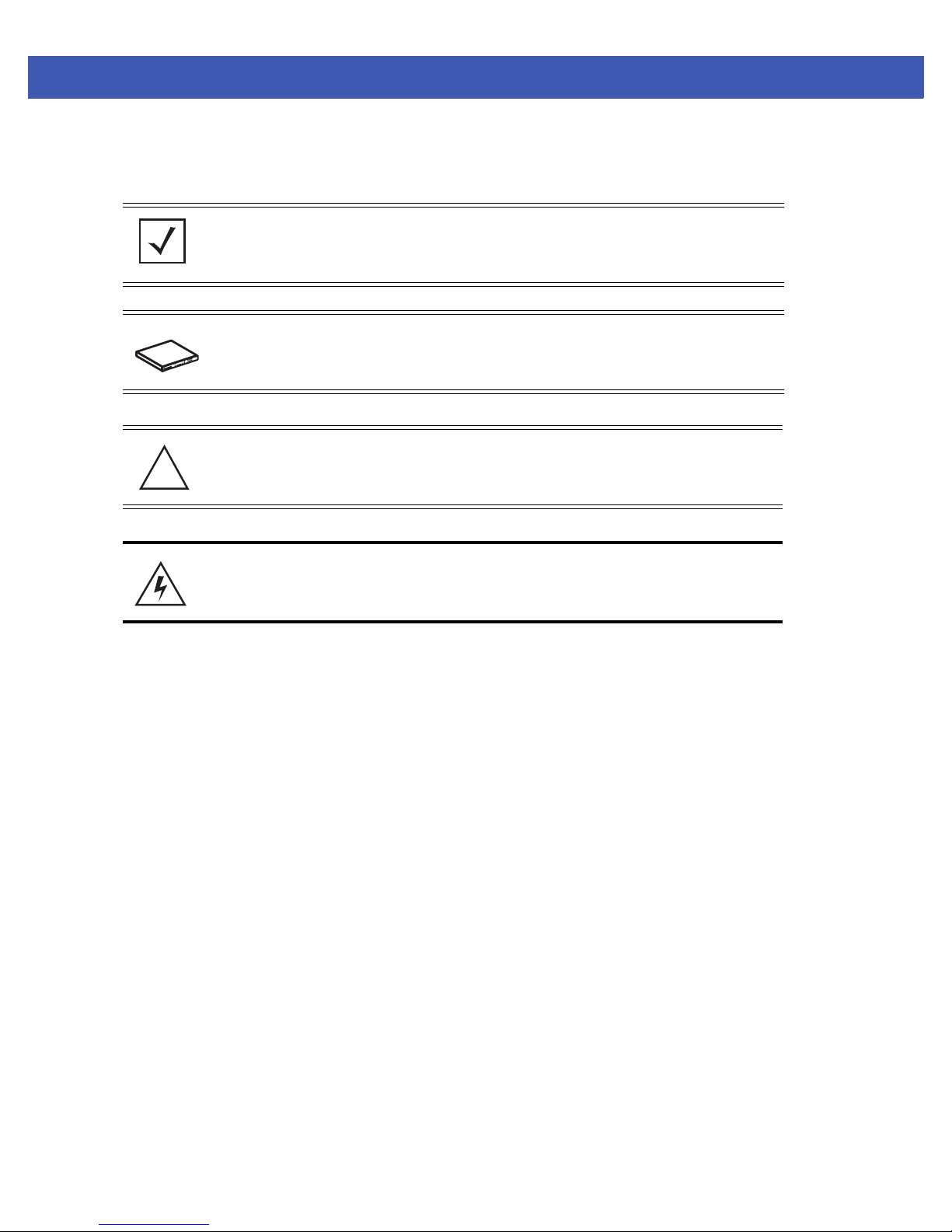
NOTE: Indicate tips or special requirements.
Switch Note: Indicates caveats unique to a RFS4000, RFS6000 or RFS7000 model switch.
CAUTION: Indicates conditions that can cause equipment damage or data loss.
!
WARNING! Indicates a condition or procedure that could result in personal injury or
equipment damage.
Notational Conventions
The following additional notational conventions are used in this document:
• Italics are used to highlight the following:
• Chapters and sections in this and related documents
• Dialog box, window and screen names
• Drop-down list and list box names
• Check box and radio button names
• Icons on a screen
• GUI text is used to highlight the following:
• Screen names
• Menu items
• Button names on a screen
• bullets (•) indicate:
• Action items
• Lists of alternatives
• Lists of required steps that are not necessarily sequential
• Sequential lists (e.g., those that describe step-by-step procedures) appear as numbered lists.
Page 17

CHAPTER 1 OVERVIEW
A Motorola Solutions RF Switch is a centralized management solution for wireless networking. It connects to
non-legacy Access Ports through Layer 2 or Layer 3 (Layer 2 is preferable, if the situation allows it).
Access ports function as radio antennas for data traffic management and routing. System configuration and intelligence
for the wireless network resides with the switch. The switch uses Access Ports to bridge data to and from wireless
devices. The wireless switch applies appropriate policies to data packets before forwarding them to their destination.
All data packets to and from wireless devices are processed by the switch, where appropriate policies are applied before
they are decapsulated and sent to their destination.
Access port configuration is managed by the switch through a Web UI Graphical User Interface (GUI), SNMP or the switch
Command Line Interface (CLI).
Switch Note: The discussion of the switch GUI within this guide is presented generically,
making it equally relevant to the RFS4000, RFS6000 and RFS7000 switch platforms. However, some subtle differences do exist amongst these baselines. These differences are noted within the specific GUI elements impacted. When these differences are noted, the
options available to each switch baseline are described in detail.
Page 18

1 - 2 WiNG 4.4 Switch System Reference Guide
1.1 Hardware Overview
The RFS4000, RFS6000 and RFS7000 are rack-mountable devices that manage all inbound and outbound traffic on the
wireless network. They provide security, network service and system management applications.
Unlike traditional wireless infrastructure devices that reside at the edge of a network, the switch uses centralized, policybased management to apply sets of rules or actions to all devices on the wireless network. The switch collects
management “intelligence” from individual Access Ports/Points and moves the collected information to the centralized
switch.
Access ports (APs) are 48V Power-over-Ethernet devices connected to the switch by an Ethernet cable. An Access Port
receives 802.11x data from MUs and forwards the data to the switch which applies the appropriate policies and routes
the packets to their destinations.
Access ports do not have software or firmware upon initial receipt from the factory. When the Access Port is first powered
on and cleared for the network, the switch initializes the Access Port and installs a small firmware file automatically.
Therefore, installation and firmware upgrades are automatic and transparent.
1.1.1 Physical Specifications
The physical dimensions and operating parameters of the RFS4000 include:
Width
Height
Depth
Weight
Operating Temperature
Operating Humidity
304.8mm (12.0 in)
44.45mm (1.75 in)
254mm (10.0 in)
2.15 Kg (4.75 lbs)
0°C - 40°C (32°F - 104°F)
5% - 85% RH, non-condensing
The physical dimensions and operating parameters of the RFS6000 include:
Width
Height
Depth
Weight
Operating Temperature
Operating Humidity
440mm (17.32 in)
44.45mm (1.75 in)
390.8mm (15.38 in)
6.35 Kg (14 lbs)
0°C - 40°C (32°F - 104°F)
5% - 85% RH, non-condensing
The physical dimensions and operating parameters of the RFS7000 include:
Width
Height
Depth
Weight
440mm (17.32 in)
44.45mm (1.75 in)
390.8mm (15.38 in)
6.12 Kg (13.5 lbs)
Page 19

Overview 1 - 3
Operating Temperature
Operating Humidity
A power cord is not supplied with a RFS4000, RFS6000 or RFS7000 model switch. Use only a correctly rated power cord
certified for the country of operation
1.1.1.1 Power Consumption
The power consumption for RFS7000, RFS6000, and RFS4000 are as follows:
RFS7000 Maximum Power Consumption: 100W
RFS6000 Maximum Power Consumption: 300W
RFS4000 AC Input Voltage: 100-240 VAC 50/60 Hz
1.1.1.2 Power Protection
To best protect the switch from unexpected power surges or other power-related problems, ensure the switch installation
meets the following guidelines:
• If possible, use a dedicated circuit to protect data processing equipment. Commercial electrical contractors are familiar
with wiring for data processing equipment and can help with the load balancing of dedicated circuits.
0°C - 40°C (32°F - 104°F)
5% - 85% RH, non-condensing
.
Maximum Power Consumption: 120W
• Install surge protection. Use a surge protection device between the electricity source and the switch.
• Install an Uninterruptible Power Supply (UPS). A UPS provides continuous power during a power outage. Some UPS
devices have integral surge protection. UPS equipment requires periodic maintenance to ensure reliability.
1.1.1.3 Cabling Requirements
A minimum of one category 6 Ethernet cables (not supplied) are required to connect the switch to the LAN and WLAN. The
cable(s) are used with the Ethernet ports on the front panel of the switch.
Switch Note: On an RFS6000 and RFS7000, Motorola Solutions recommends connecting
via the Management Ethernet (ME) interface to better ensure secure and easier management. The ME interface is connected to the management VLAN, and is therefore separate
from production VLANs.
Switch Note: On the RFS4000 and RFS6000 the Uplink (UP) port is the preferred method
of connecting the switch to the network. The Uplink port has its own dedicated 1Gbps connection which is unaffected by internal traffic across the GE ports.
The console cable included with the switch connects the switch to a computer running a serial terminal emulator program
to access the switch’s Command Line Interface (CLI) for initial configuration. An initial configuration is described within
the Installation Guide shipped with each switch.
Page 20
1 - 4 WiNG 4.4 Switch System Reference Guide
1.2 Software Overview
The switch includes a robust set of features. The features are listed and described in the following sections:
• Infrastructure Features
• Wireless Switching
• Wired Switching
• Management Features
• Security Features
• Supported Access Ports/Points
NOTE: The Motorola Solutions RF Management Software is a recommended utility to
plan the deployment of the switch and view its configuration once operational in the field.
Motorola Solutions RFMS can help optimize the positioning and configuration of a switch
in respect to a WLAN’s MU throughput requirements and can help detect rogue devices.
For more information, refer to the Motorola Solutions Website.
1.2.1 Infrastructure Features
The switch includes the following Infrastructure features:
• Installation Feature
• Configuration Management
• Diagnostics
• Serviceability
• Tracing / Logging
• Process Monitor
• Hardware Abstraction Layer and Drivers
• Redundancy
• Secure Network Time Protocol (SNTP)
• Password Recovery
1.2.1.1 Installation Feature
The upgrade/downgrade of the switch can be performed at boot time using one of the following methods:
•Web UI
•DHCP
•CLI
•SNMP
• Patches
The switch has sufficient non-volatile memory to store two firmware images. Having a second firmware image provides a
backup in case of failure of the primary image. It also allows for testing of new firmware on a switch with the ability to
easily revert to a previous image.
Page 21

1.2.1.2 Configuration Management
The switch supports the redundant storage of configuration files to protect against corruption during a write operation and
ensure (at any given time) a valid configuration file exists. If writing the configuration file fails, it is rolled back and a prewrite file is used.
Text Based Configuration
The configuration is stored a in human readable format (as a set of CLI commands).
1.2.1.3 Diagnostics
The following diagnostics are available:
1. In-service Diagnostics – In-service diagnostics provide a range of automatic health monitoring features ensuring both
the system hardware and software are in working order. In-service-diagnostics continuously monitor available physical
characteristics (as detailed below) and issue log messages when warning or error thresholds are reached. There are
three types of in-service diagnostics:
• Hardware – Ethernet ports, chip failures, system temperature via the temperature sensors provided by the
hardware, etc.
• Software – CPU load, memory usage, etc.
Overview 1 - 5
• Environmental – CPU and air temperature, fans speed, etc.
2. Out-of-service Diagnostics – Out-of-service diagnostics are a set of intrusive tests run from the user interface. Out-ofservice diagnostics cannot be run while the switch is in operation. Intrusive tests include:
• Ethernet loopback tests
• RAM tests, Real Time Clock tests, etc.
3. Manufacturing Diagnostics – Manufacturing diagnostics are a set of diagnostics used by manufacturing to inspect
quality of hardware.
1.2.1.4 Serviceability
A special set of Service CLI commands are available to provide additional troubleshooting capabilities for service
personnel (access to Linux services, panic logs, etc.). Only authorized users or service personnel are provided access to the
Service CLI.
A built-in Packet Sniffer enables service personnel and users to capture incoming and outgoing packets in a buffer.
The switch also collects statistics for RF activity, Ethernet port activity etc. RF statistics include roaming stats, packet
counters, octets tx/rx, signal, noise SNR, retry, and information for each MU.
1.2.1.5 Tracing / Logging
Log messages are well-defined and documented system messages with various destinations. They are numbered and
referenced by ID. Each severity level group, can be configured separately to go to either the serial console, telnet interface,
log file or remote syslog server.
Trace messages are more free-form and are used mainly by support personnel for tracking problems. They are enabled or
disabled via CLI commands. Trace messages can go to a log file, the serial console, or the current tty.
Log and trace messages are interleaved in the same log file, so chronological order is preserved. Log and trace messages
from different processes are similarly interleaved in the same file for the same reason.
Log message format is similar to the format used by syslog messages (RFC 3164). Log messages include message severity,
source (facility), the time the message was generated and a textual message describing the situation triggering the event.
For more information on using the switch logging functionality, see Configuring System Logging on page 8-8.
Page 22

1 - 6 WiNG 4.4 Switch System Reference Guide
1.2.1.6 Process Monitor
The switch Process Monitor checks to ensure processes under its control are up and running. Each monitored process
sends periodic heartbeat messages. A process that is down (due to a software crash or stuck in an endless loop) is
detected when its heartbeat is not received. Such a process is terminated (if still running) and restarted (if configured) by
the Process Monitor.
1.2.1.7 Hardware Abstraction Layer and Drivers
The Hardware Abstraction Layer (HAL) provides an abstraction library with an interface hiding hardware/platform specific
data. Drivers include platform specific components such as Ethernet, Flash Memory storage and thermal sensors.
1.2.1.8 Redundancy
Using switch redundancy, up to 12 switches can be configured in a redundancy group (and provide group monitoring). In
the event of a switch failure, an existing cluster member assumes control. Therefore, the switch supported network is
always up and running even if a switch fails or is removed for maintenance or a software upgrade.
The following redundancy features are supported:
• Up to 12 switch redundancy members are supported in a single group. Each member is capable of tracking statistics
for the entire group in addition to their own.
• Each redundancy group is capable of supporting an Active/Active configuration responsible for group load sharing.
• Members within the same redundancy group can be deployed across different subnets.
• APs are load balanced across members of the group.
• Licenses are aggregated across the group. When a new member joins the group, the new member can leverage the
Access Port adoption license(s) of existing members.
• Each member of the redundancy group (including the reporting switch) is capable of displaying cluster performance
statistics for all members in addition to their own.
• Centralized redundancy group management using the switch CLI.
For more information on configuring the switch for redundancy support, see
Configuring Switch Redundancy & Clustering on page 5-34.
1.2.1.9 Secure Network Time Protocol (SNTP)
Secure Network Time Protocol (SNTP) manages time and/or network clock synchronization within the switch managed
network. SNTP is a client/server implementation. The switch (a SNTP client) periodically synchronizes its clock with a
master clock (an NTP server). For example, the switch resets its clock to 07:04:59 upon reading a time of 07:04:59 from its
designated NTP server. Time synchronization is recommended for the switch’s network operations. The following holds
true:
• The switch can be configured to provide NTP services to NTP clients.
• The switch can provide NTP support for user authentication.
• Secure Network Time Protocol (SNTP) clients can be configured to synchronize switch time with an external NTP server.
For information on configuring the switch to support SNTP, see Configuring Secure NTP on page 5-23.
1.2.1.10 Password Recovery
The access point has a means of restoring its password to its default value. Doing so also reverts the access point’s
security, radio and power management configuration to their default settings. Only an installation professional should
reset the access point’s password and promptly define a new restrictive password.
Page 23

To contact Motorola Solutions Support in the event of a password reset requirement, go to http://www.motorola.com/
Business/US-EN/Support
CAUTION: Only a qualified installation professional should set or restore the access
point’s radio and power management configuration in the event of a password reset.
!
1.2.2 Wireless Switching
The switch supports the following wireless switching features:
• Adaptive AP
• Physical Layer Features
• Rate Limiting
• Proxy-ARP
• HotSpot / IP Redirect
• IDM (Identity Driven Management)
• Voice Prioritization
Overview 1 - 7
• Self Healing
• Wireless Capacity
• AP and MU Load Balancing
• Wireless Roaming
• Power Save Polling
• QoS
• Wireless Layer 2 Switching
• Automatic Channel Selection
• WMM-Unscheduled APSD
• Multiple VLANs per WLAN
1.2.2.1 Adaptive AP
An adaptive AP (AAP) is an AP-5131 or AP-7131 Access Point adopted by a wireless switch. The management of an AAP
is conducted by the switch, once the Access Point connects to the switch and receives its AAP configuration.
An AAP provides:
• local 802.11 traffic termination
• local encryption/decryption
• local traffic bridging
• tunneling of centralized traffic to the wireless switch
The connection between the AAP and the switch can be secured using IPSec depending on whether a secure WAN link
from a remote site to the central site already exists.
The switch can be discovered using one of the following mechanisms:
• DHCP
• Switch fully qualified domain name (FQDN)
Page 24

1 - 8 WiNG 4.4 Switch System Reference Guide
• Static IP addresses
The benefits of an AAP deployment include:
• Centralized Configuration Management & Compliance - Wireless configurations across distributed sites can be
centrally managed by the wireless switch or cluster.
• WAN Survivability - Local WLAN services at a remote sites are unaffected in the case of a WAN outage.
• Securely extend corporate WLAN's to stores for corporate visitors - Small home or office deployments can utilize the
feature set of a corporate WLAN from their remote location.
• Maintain local WLAN's for specific applications - WLANs created and supported locally can be concurrently supported
with your existing infrastructure.
For an overview of AAP and how it is configured and deployed using the switch and Access Point, see
Adaptive AP Overview.
1.2.2.2 Physical Layer Features
802.11a
• DFS Radar Avoidance – Dynamic Frequency Selection (DFS) is mandatory for WLAN equipment intended to operate in
the frequency bands 5150 MHz to 5350 MHz and 5470 MHz to 5725 MHz when in countries of the EU.
The purpose of DFS is:
• Detect interference from other systems and avoid co-channeling with those systems (most notably radar systems).
• Provide uniform spectrum loading across all devices.
This feature is enabled automatically when the country code indicates that DFS is required for at least one of the
frequency bands that are allowed in the country.
• TPC – Transmit Power Control (TPC) meets the regulatory requirement for maximum power and mitigation for each
channel. TPC functionality is enabled automatically for every AP that operates on the channel.
802.11bg
• Dual mode b/g protection – ERP builds on the payload data rates of 1 and 2 Mbit/s that use DSSS modulation and
builds on the payload data rates of 1, 2, 5.5, and 11 Mbit/s, that use DSSS, CCK, and optional PBCC modulations. ERP
provides additional payload data rates of 6, 9, 12, 18, 24, 36, 48, and 54 Mbit/s. The transmission and reception
capability for 1, 2, 5.5, 11, 6, 12, and 24 Mbit/s data rates is mandatory.
Two additional optional ERP-PBCC modulation modes with payload data rates of 22 and 33 Mbit/s are defined. An ERPPBCC station may implement 22 Mbit/s alone or 22 and 33 Mbit/s. An optional modulation mode (known as DSSSOFDM) is also incorporated with payload data rates of 6, 9, 12, 18, 24, 36, 48, and 54 Mbit/s.
• Short slot protection – The slot time is 20 µs, except an optional 9 µs slot time may be used when the BSS consists of
only ERP STAs capable of supporting this option. The optional 9 µs slot time should not be used if the network has one
or more non-ERP STAs associated. For IBSS, the Short Slot Time field is set to 0, corresponding to a 20 µs slot time.
1.2.2.3 Rate Limiting
Rate Limiting limits the maximum rate sent to or received from the wireless network per mobile unit. It prevents any single
user from overwhelming the wireless network. It can also provide differential service for service providers. The uplink and
downlink rate limits are usually configured on the radius server using Motorola Solutions vendor specific attributes. The
switch extracts the rate limits from radius server response. When such attributes are not present, the global settings on
the switch are then applied.
Page 25

1.2.2.4 Proxy-ARP
Proxy ARP is provided for MU's whose IP address is known. The WLAN generates an ARP reply on behalf of a MU (if the
MU's IP address is known). The ARP reply contains the MAC address of the MU (not the MAC address of switch). Thus,
the MU does not awaken to send ARP replies (increasing MU battery life and conserving wireless bandwidth).
If an MU goes into PSP without transmitting at least one packet, its Proxy ARP will not work.
1.2.2.5 HotSpot / IP Redirect
A hotspot is a Web page users are forced to visit before they are granted access to the Internet. With the advent of Wi-Fi
enabled client devices (such as laptops and PDAs) commercial hotspots are common and can be found at many airports,
hotels and coffee shops. The hotspot re-directs the user’s traffic on hotspot enabled WLANs to a web page that requires
them to authenticate before granting access to the WLAN. The following is a typical sequence for hotspot access:
1. A visitor with a laptop requires hotspot access at a site.
2. A user ID/ Password and hotspot ESSID is issued by the site receptionist or IT staff.
3. The user connects their laptop to this ESSID.
4. The laptop receives its IP configuration via DHCP.
5. The user opens a Web browser and connects to their home page.
Overview 1 - 9
6. The switch re-directs them to the hotspot Web page for authentication.
7. The user enters their User ID/ Password.
8. A Radius server authenticates the user.
9. Upon successful authentication, the user is directed to a Welcome Page that lists (among other things) an Acceptable
Use Policy.
10.The user agrees to the usage terms and is granted access to the Internet. (or other network services).
To setup a hotspot, create a WLAN ESSID and select Hotspot authentication from the Authentication menu. This is simply
another way to authenticate a WLAN user, as it would be impractical to authenticate visitors using 802.1x. For information
on configuring a hotspot, see Configuring Hotspots on page 4-36.
1.2.2.6 IDM (Identity Driven Management)
Radius authentication is performed for all protocols using a Radius-based authentication scheme (such as EAP). Identity
driven management is provided using a Radius client. The following IDMs are supported:
• User based SSID authentication — Denies authentication to MUs if associated to a ESSID configured differently by
their Radius server.
•User based VLAN assignment — Allows the switch to extract VLAN information from the Radius server.
• User based QoS — Enables QoS for the MU based on settings within the Radius Server.
1.2.2.7 Voice Prioritization
The switch has the capability of having its QoS policy configured to prioritize network traffic requirements for associated
MUs. Use QoS to enable voice prioritization for devices using voice as its transmission priority.
Voice prioritization allows you to assign priority to voice traffic over data traffic, and (if necessary) assign legacy voice
supported devices (non WMM supported voice devices) additional priority.
Currently voice support implies the following:
• Spectralink voice prioritization - Spectralink sends packets that allow the switch to identify these MU's as voice MU's.
Thereafter, any UDP packet sent by these MU's is prioritized ahead of data.
Page 26

1 - 10 WiNG 4.4 Switch System Reference Guide
• Strict priority - The prioritization is strict.
• Multicast prioritization - Multicast frames that match a configured multicast mask bypass the PSP queue. This features
permits intercom mode operation without delay (even in the presence of PSP MU's).
For more information on configuring voice prioritization for a target WLAN, see
Configuring WMM on page 4-64.
1.2.2.8 Self Healing
Self Healing is the ability to dynamically adjust the RF network by modifying transmit power and/or supported rates upon
an AP failure.
In a typical RF network deployment, APs are configured for Transmit Power below their maximum level. This allows the Tx
Power to be increased when there is a need to increase coverage when an AP fails.
When an AP fails, the Tx Power/Supported rates of APs neighboring the failed AP are adjusted. The Tx power is increased
and/or Supported rates are decreased. When the failed AP becomes operational again, Neighbor AP’s Tx Power/
Supported rates are brought back to the levels before the self healing operation changed them.
The switch detects an AP failure when:
• AP stops sending heartbeats.
• AP beacons are no longer being sent. This is determined when other detector APs are no longer hearing beacons from
a particular AP.
Configure 0 (Zero) or more APs to act as either:
• Detector APs — Detector APs scan all channels and send beacons to the switch which uses the information for selfhealing.
• Neighbor APs — When an AP fails, neighbor APs assist in self healing.
• Self Healing Actions — When an AP fails, actions are taken on the neighbor APs to do
self-healing.
Detector APs
Configure an AP in either – Data mode (the regular mode) or Detector mode.
In Detector mode, an AP scans all channels at a configurable rate and forwards received beacons the switch. The switch
uses the information to establish a receive signal strength baseline over a period of time and initiates self-healing
procedures (if necessary).
Neighbor Configuration
Neighbor detect is a mechanism allowing an AP to detect its neighbors as well as their signal strength. This enables you
to verify your installation and configure it for self-healing when an AP fails.
Self Healing Actions
If AP1 detects AP2 and AP3 as its neighbors, you can assign failure actions to AP2 and AP3 whenever AP1 fails.
Assign up to four self healing actions:
1. No action
2. Decrease supported rates
3. Increase Tx power
4. Both 2 and 3.
You can specify the Detector AP (AP2 or AP3) to stop detecting and adopt the RF settings of the failed AP. For more
information on configuring self healing, see Configuring Self Healing on page 5-54.
Page 27

1.2.2.9 Wireless Capacity
Wireless capacity specifies the maximum numbers of MUs, Access Ports and wireless networks usable by a switch.
Wireless capacity is largely independent of performance. Aggregate switch performance is divided among the switch
clients (MUs and Access Ports) to find the performance experienced by a given user. Each switch platform is targeted at
specific market segments, so the capacity of each platform is chosen appropriately. Wireless switch capacity is measured
by:
• The maximum number of WLANs per switch
• The maximum number of Access Ports adopted per switch
• The maximum number of MUs per switch
• The maximum number of MUs per Access Port.
The actual number of Access Ports adoptable by a switch is defined by the switch licenses or the total licenses in the
cluster in which this switch is a member.
1.2.2.10 AP and MU Load Balancing
Fine tune a network to evenly distribute data and/or processing across available resources. Refer to the following:
• MU Balancing Across Multiple APs
Overview 1 - 11
• AP Balancing Across Multiple Switches
MU Balancing Across Multiple APs
Per the 802.11 standard, AP and MU association is a process conducted independently of the switch. 802.11 provides
message elements used by the MU firmware to influence roaming decisions. The switch implements the following MU
load balancing techniques:
• 802.11e admission control — 1 byte: channel utilization % and 1 byte: MU count is sent in QBSS Load Element in
beacons to MU.
• Motorola Solutions load balancing element (proprietary) — 2 byte: MU Count are sent in beacon to MU.
For more information on Access Port adoption in a layer 3 environment, see Configuring Layer 3 Access Port Adoption on
page 4-134.
Page 28
1 - 12 WiNG 4.4 Switch System Reference Guide
AP Balancing Across Multiple Switches
At adoption, the AP solicits and receives multiple adoption responses from the switches on the network. These adoption
responses contain preference and loading information the AP uses to select the optimum switch to be adopted by. Use this
mechanism to define which APs are adopted by which switches. By default, the adoption algorithm generally distributes
AP adoption evenly among the switches available.
NOTE: Port adoption per switch is determined by the number of licenses acquired.
For more information on Access Port adoption in a layer 3 environment, see Configuring Layer 3 Access Port Adoption on
page 4-134.
1.2.2.11 Wireless Roaming
The following types of wireless roaming are supported by the switch:
• Interswitch Layer 2 Roaming
• Interswitch Layer 3 Roaming
• Fast Roaming
• International Roaming
• MU Move Command
• Power Save Polling
Interswitch Layer 2 Roaming
An associated MU (connected to a switch) can roam to another Access Port connected to a different switch. Both switches
must be on the same Layer 2 domain. Authentication information is not shared between the switches, nor are buffered
packets on one switch transferred to the other. Pre-authentication between the switch and MU allows faster roaming.
Interswitch Layer 3 Roaming
Interswitch Layer 3 roaming allows MUs to roam between switches which are not on the same LAN or IP subnet without
the MUs or the rest of the network noticing. This allows switches to be placed in different locations on the network without
having to extend the MU VLANs to every switch.
Fast Roaming
Using 802.11i can speed up the roaming process from one AP to another. Instead of doing a complete 802.1x authentication
each time a MU roams between APs, 802.11i allows a MU to re-use previous PMK authentication credentials and perform
a four-way handshake. This speeds up the roaming process. In addition to reusing PMKs on previously visited APs,
Opportunistic Key Caching allows multiple APs to share PMKs amongst themselves. This allows an MU to roam to an AP
it has not previously visited and reuse a PMK from another AP to skip the 802.1x authentication.
International Roaming
The wireless switch supports international roaming per the 802.11d specification.
MU Move Command
As a value added proprietary feature between Motorola Solutions infrastructure products and Motorola Solutions MUs, a
move command has been introduced. The move command permits an MU to roam between ports connected to the same
switch without the need to perform the full association and authentication defined by the 802.11 standard. The move
command is a simple packet up/packet back exchange with the Access Port. Verification of this feature is dependent on
its implementation in one or more mobile units.
Page 29

1.2.2.12 Power Save Polling
An MU uses Power Save Polling (PSP) to reduce power consumption. When an MU is in PSP mode, the switch buffers its
packets and delivers them using the DTIM interval. The PSP-Poll packet polls the AP for buffered packets. The PSP null
data frame is used by the MU to signal the current PSP state to the AP.
1.2.2.13 QoS
QoS provides a data traffic prioritization scheme. QoS reduces congestion from excessive traffic.
If there is enough bandwidth for all users and applications (unlikely because excessive bandwidth comes at a very high
cost), then applying QoS has very little value. QoS provides policy enforcement for mission-critical applications and/or
users that have critical bandwidth requirements when the switch’s bandwidth is shared by different users and
applications.
QoS helps ensure each WLAN on the switch receives a fair share of the overall bandwidth, either equally or as per the
proportion configured. Packets directed towards MUs are classified into categories such as Management, Voice and Data.
Packets within each category are processed based on the weights defined for each WLAN.
The switch supports the following QoS mechanisms:
802.11e QoS
Overview 1 - 13
802.11e enables real-time audio and video streams to be assigned a higher priority over data traffic. The switch supports
the following 802.11e features:
•Basic WMM
• WMM Linked to 802.1p Priorities
• WMM Linked to DSCP Priorities
• Fully Configurable WMM
• Admission Control
• Unscheduled-APSD
• TSPEC Negotiation
• Block ACKQBSS Beacon Element
802.1p Support
802.1p is a standard for providing QoS in 802-based networks. 802.1p uses three bits to allow switches to re-order packets
based on priority level.
Voice QoS
When switch resources are shared between a Voice over IP (VoIP) conversation and a file transfer, bandwidth is normally
exploited by the file transfer, thus reducing the quality of the conversation or even causing it to disconnect. With QoS, a
VoIP conversation (a real-time session), receives priority, maintaining a high level of voice quality. Voice QoS ensures:
• Strict Priority
• Spectralink Prioritization
• VOIP Prioritization (IP ToS Field)
• Multicast Prioritization
Page 30
1 - 14 WiNG 4.4 Switch System Reference Guide
Data QoS
The switch supports the following data QoS techniques:
• Egress Prioritization by WLAN
• Egress Prioritization by ACL
DCSCP to AC Mapping
The switch provides arbitrary mapping between Differentiated Services Code Point (DCSCP) values and WMM Access
Categories. This mapping can be set manually.
1.2.2.14 Wireless Layer 2 Switching
The switch supports the following layer 2 wireless switching techniques:
•WLAN to VLAN
• MU User to VLAN
•WLAN to GRE
1.2.2.15 Automatic Channel Selection
Automatic channel selection works sequentially as follows:
1. When a new AP is adopted, it scans each channel. However, the switch does not forward traffic at this time.
2. The switch then selects the least crowded channel based on the noise and traffic detected on each channel.
3. The algorithm used is a simplified maximum entropy algorithm for each radio, where the signal strength from adjoining
AP's/MU's associated to adjoining AP's is minimized.
4. The algorithm ensures adjoining AP's are as far away from each other as possible (in terms of channel assignment).
NOTE: Individual radios can be configured to perform automatic channel selection.
1.2.2.16 WMM-Unscheduled APSD
This feature is also known as WMM Power Save or WMM-UPSD (Unscheduled Power Save Delivery). WMM-UPSD
defines an unscheduled service period, which are contiguous periods of time during which the switch is expected to be
awake. If the switch establishes a downlink flow and specifies UPSD power management, it requests (and the AP delivers)
buffered frames associated with that flow during an unscheduled service period. The switch initiates an unscheduled
service period by transmitting a trigger frame. A trigger frame is defined as a data frame (e.g. an uplink voice frame)
associated with an uplink flow with UPSD enabled. After the AP acknowledges the trigger frame, it transmits the frames
in its UPSD power save buffer addressed to the triggering switch.
UPSD is well suited to support bi-directional frame exchanges between a voice STA and its AP.
1.2.2.17 Multiple VLANs per WLAN
The switch permits the mapping of a WLAN to more than one VLAN. When a MU associates with a WLAN, the MU is
assigned a VLAN by means of load balance distribution. The VLAN is picked from a pool assigned to the WLAN. The switch
tracks the number of MUs per VLAN, and assigns the least used/loaded VLAN to the MU. This number is tracked on a perWLAN basis.
A broadcast key, unique to the VLAN, encrypts packets coming from the VLAN. If two or more MUs are on two different
VLANs, they both hear the broadcast packet, but only one can decrypt it. The switch provides each MU a unique VLAN
broadcast key as part of the WPA2 handshake or group key update message of a WPA handshake.
Page 31

Overview 1 - 15
Limiting Users Per VLAN
Not all VLANs within a single WLAN must have the same DHCP pool size. Assign a user limit to each VLAN to allow the
mapping of different pool sizes.
Specify the VLAN user limit. This specifies the maximum number of MUs associated with a VLAN (for a particular WLAN).
When the maximum MU limit is reached, no more MUs can be assigned to that VLAN.
Packet Flows
There are four packet flows supported when the switch is configured to operate with multiple VLAN per WLAN:
• Unicast From Mobile Unit – Frames are decrypted, converted from 802.11 to 802.3 and switched to the wired side of
the VLAN dynamically assigned to the mobile device. If the destination is another mobile device on the wireless side,
the frame is encrypted and switched over the air.
• Unicast To Mobile Unit – The frame is checked to ensure the VLAN is same as that assigned to the mobile device. It is
then converted to an 802.11 frame, encrypted, and sent over the air.
• Multicast/Broadcast From Mobile Unit – The frame is treated as a unicast frame from the MU, with the exception that
it is encrypted with the per-VLAN broadcast key and then transmitted over the air.
• Multicast/Broadcast from Wired Side – If the frame comes from a VLAN mapped to the WLAN, it’s encrypted using a
per-VLAN broadcast key and transmitted over the air. Only MUs on that VLAN have a broadcast key that can decrypt
this frame. Other MUs receive it, but discard it.
In general, when there are multiple VLANs mapped to the same WLAN, the broadcast buffer queue size scales linearly
to accommodate a potential increase in the broadcast packet stream.
Roaming within the Switch
When a MU is assigned to a VLAN, the switch registers the VLAN assignment in its credential cache. If the MU roams, it
is assigned back to its earlier assigned VLAN. The cache is flushed upon detected MU inactivity or if the MU associates
over a different WLAN (on the same switch).
Roaming across a Cluster
MUs roam amongst switch cluster members. The switch must ensure a VLAN remains unchanged as an MU roams. This
is accomplished by passing MU VLAN information across the cluster using the interface used by a hotspot. It automatically
passes the username/password across the credential caches of the member switches. This ensures a VLAN MU
association is maintained even while the MU roams amongst cluster members.
Roaming across a Layer 3 Mobility Domain
When an MU roams amongst switches in different Layer 3 mobility domains, Layer 3 ensures traffic is tunneled back to
the correct VLAN (on the home switch).
Interaction with Radius Assigned VLANs
Multiple VLANs per WLAN can co-exist with VLANs assigned by a Radius server. Upon association, an MU is assigned to
a VLAN from a pool of available VLANs. When the Radius server assigns the user another VLAN, MU traffic is forwarded
to that VLAN.
When 802.1x is used, traffic from the MU is dropped until authentication is completed. None of the MU data is switched
onto the temporarily VLAN. A Radius assigned VLAN overrides the statically assigned VLAN.
If the Radius assigned VLAN is among the VLANs assigned to a WLAN, it is available for VLAN assignment in the future.
If the Radius assigned VLAN is not one of the VLANs assigned to a WLAN, it is not available for future VLAN assignment.
To configure Multiple VLANs for a single WLAN, see Assigning Multiple VLANs per WLAN on page 4-32.
Page 32

1 - 16 WiNG 4.4 Switch System Reference Guide
1.2.3 Wired Switching
The switch includes the following wired switching features:
• DHCP Servers
• DHCP User Class Options
• DDNS
• VLAN Enhancements
• Interface Management
1.2.3.1 DHCP Servers
Dynamic Host Configuration Protocol (DHCP) allows hosts on an IP network to request and be assigned IP addresses as
well as discover information about the network to which they are attached. Each subnet may be configured with its own
address pool. Whenever a DHCP client requests an IP address, the DHCP server assigns an IP address from that subnet’s
address pool.
When a DHCP server allocates an address for a DHCP client, the client is assigned a lease, which expires after an predetermined interval. Before a lease expires, clients (to which leases are assigned) are expected to renew them to continue
to use the addresses. Once the lease expires, the client is no longer permitted to use the leased IP address. For information
on defining the switch DHCP configuration, see
DHCP Server Settings on page 5-4.
1.2.3.2 DHCP User Class Options
A DHCP Server groups clients based on defined user-class option values. Clients with a defined set of user-class values
are segregated by class. The DHCP Server can associate multiple classes to each pool. Each class in a pool is assigned an
exclusive range of IP addresses.
DHCP clients are compared against classes. If the client matches one of the classes assigned to the pool, it receives an IP
address from the range assigned to the class. If the client doesn't match any of the classes in the pool, it receives an IP
address from a default pool range (if defined).
Multiple IP addresses for a single VLAN allow the configuration of multiple IP addresses, each belonging to different
subnet. Class configuration allows a DHCP client to obtain an address from the first pool to which the class is assigned.
For more information, see Configuring the DHCP User Class on page 5-18.
1.2.3.3 DDNS
Dynamic DNS (DDNS) keeps a domain name linked to a changing IP address. Typically, when a user connects to a network,
the user’s ISP assigns it an unused IP address from a pool of IP addresses. This address is only valid for a short period.
Dynamically assigning IP addresses increases the pool of assignable IP addresses. DNS maintains a database to map a
given name to an IP address used for communication on the Internet. The dynamic assignment of IP addresses makes it
necessary to update the DNS database to reflect the current IP address for a given name. Dynamic DNS updates the DNS
database to reflect the correct mapping of a given name to an IP address.
1.2.3.4 VLAN Enhancements
The switch has incorporated the following VLAN enhancements:
• Network interfaces operate in either trunk or access modes.
• A network interface in access mode can only send and receive untagged packets.
• A trunk port can now receive both tagged and untagged packets. Each ethernet port is assigned a native VLAN.
Page 33

• You can now configure a set of allowed VLANs on a trunk port. Packets received on this port that belong to other VLANs
are discarded.
1.2.3.5 Interface Management
The switch’s physical interfaces auto-negotiate speed and duplex. The switch also allows:
• Manual bandwidth configuration of a physical interface speed to 10/100/1000Mbps.
• Manual duplex configuration of a physical interface to Full Duplex or Half Duplex.
• Manual configuration of administrative shutdown of a physical interface.
1.2.4 Management Features
The switch supports the following management features:
• A secure, browser-based management console
•A Command Line Interface (CLI) accessible via the serial port or through Telnet or a Secure Shell (SSH) application
• A CLI Service mode enabling the capture of system status information that can be sent to Motorola Solutions personnel
for use in problem resolution
• The support for Simple Network Management Protocol (SNMP) version 3 as well as SNMP version 2
Overview 1 - 17
• Upload and download of Access Port firmware and configuration files using TFTP and FTP.
• Transfer of firmware and configuration files using Compact Flash (RFS7000 only) or USB (RFS6000 and RFS7000
platforms only)
• The graphing of wireless statistics
• A GUI dashboard summary of system status
• Multi switch management via MSP application
• Heat map support for RF deployment
• Secure guest access with specific permission intervals
• Switch discovery enabling users to discover each Motorola Solutions switch on the specified network.
Page 34

1 - 18 WiNG 4.4 Switch System Reference Guide
1.2.5 Security Features
Switch security can be classified into wireless security and wired security.
The switch includes the following wireless security features:
• Encryption and Authentication
• MU Authentication
• Secure Beacon
• MU to MU Disallow
• 802.1x Authentication
• WIPS
• Rogue AP Detection
The switch includes the following wired security features:
• ACLs
• Local Radius Server
• IPSec VPN
• NAT
• Certificate Management
1.2.5.1 Encryption and Authentication
The switch can implement the following encryption and authentication types:
• WEP
• WPA
• WPA2
• Keyguard-WEP
WEP
Wired Equivalent Privacy (WEP) is an encryption scheme used to secure wireless networks. WEP was intended to provide
comparable confidentiality to a traditional wired network, hence the name. WEP had many serious weaknesses and hence
was superseded by Wi-Fi Protected Access (WPA). Regardless, WEP still provides a level of security that can deter casual
snooping. For more information on configuring WEP for a target WLAN, see Configuring WEP 64 on page 4-53 or
Configuring WEP 128 / KeyGuard on page 4-54.
WEP uses passwords entered manually at both ends (Pre Shared Keys). Using the RC4 encryption algorithm, WEP originally
specified a 40-bit key, but was later boosted to 104 bits. Combined with a 24-bit initialization vector, WEP is often touted
as having a 128-bit key.
Page 35

Overview 1 - 19
WPA
WPA is designed for use with an 802.1X authentication server, which distributes different keys to each user. However, it
can also be used in a less secure pre-shared key (PSK) mode, where every user is given the same passphrase.
WPA uses Temporal Key Integrity Protocol (TKIP), which dynamically changes keys as the system is used. When combined
with the much larger Initialization Vector, it defeats well-known key recovery attacks on WEP. For information on
configuring WPA for a WLAN, see Configuring WPA/WPA2 using TKIP and CCMP on page 4-56.
WPA2
WPA2 uses a sophisticated key hierarchy that generates new encryption keys each time a MU associates with an Access
Point. Protocols including 802.1X, EAP and Radius are used for strong authentication. WPA2 also supports the TKIP and
AES-CCMP encryption protocols. For information on configuring WPA for a WLAN, see Configuring WPA/WPA2 using TKIP
and CCMP on page 4-56.
Keyguard-WEP
KeyGuard is Motorola Solutions’ proprietary dynamic WEP solution. Motorola Solutions (upon hearing of the
vulnerabilities of WEP) developed a non standard method of rotating keys to prevent compromises. Basically, KeyGuard is
TKIP without the message integrity check. KeyGuard is proprietary to Motorola Solutions MUs only. For information on
configuring KeyGuard for a WLAN, see Configuring WEP 128 / KeyGuard on page 4-54.
1.2.5.2 MU Authentication
The switch uses the following authentication schemes for MU association:
• Kerberos
• 802.1x EAP
• MAC ACL
Refer to Editing the WLAN Configuration on page 4-27 for additional information.
Kerberos
Kerberos allows for mutual authentication and end-to-end encryption. All traffic is encrypted and security keys are
generated on a per-client basis. Keys are never shared or reused, and are automatically distributed in a secure manner. For
information on configuring Kerberos for a WLAN, see
Configuring Kerberos on page 4-35.
802.1x EAP
802.1x EAP is the most secure authentication mechanism for wireless networks and includes
EAP-TLS, EAP-TTLS and PEAP. The switch is a proxy for Radius packets. An MU does a full 802.11 authentication and
association and begins transferring data frames. The switch realizes the MU needs to authenticate with a Radius server
and denies any traffic not Radius related. Once Radius completes its authentication process, the MU is allowed to send
other data traffic. You can use either an onboard Radius server or internal Radius Server for authentication. For information
on configuring 802.1x EAP for a WLAN, see Configuring 802.1x EAP on page 4-34.
MAC ACL
The MAC ACL feature is basically a dynamic MAC ACL where MUs are allowed/denied access to the network based on
their configuration on the Radius server. The switch allows 802.11 authentication and association, then checks with the
Radius server to see if the MAC address is allowed on the network. The Radius packet uses the MAC address of the MU
as both the username and password (this configuration is also expected on the Radius server). MAC-Auth supports all
encryption types, and (in case of 802.11i) the handshake is completed before the Radius lookup begins. For information on
configuring 802.1x EAP for a WLAN, see Configuring MAC Authentication on page 4-46.
Page 36

1 - 20 WiNG 4.4 Switch System Reference Guide
1.2.5.3 Secure Beacon
Devices in a wireless network use Service Set Identifiers (SSIDs) to communicate. An SSID is a text string up to 32 bytes
long. An AP in the network announces its status by using beacons. To avoid others from accessing the network, the most
basic security measure adopted is to change the default SSID to one not easily recognizable, and disable the broadcast of
the SSID.
The SSID is a code attached to all packets on a wireless network to identify each packet as part of that network. All
wireless devices attempting to communicate with each other must share the same SSID. Apart from identifying each
packet, the SSID also serves to uniquely identify a group of wireless network devices used in a given service set.
1.2.5.4 MU to MU Disallow
Use MU to MU Disalllow to restrict MU to MU communication within a WLAN. The default is ‘no’, which allows MUs to
exchange packets with other MUs. It does not prevent MUs on other WLANs from sending packets to this WLAN. You
would have to enable MU to MU Disallow on the other WLAN. To define how MU to MU traffic is permitted for a WLAN,
see Editing the WLAN Configuration on page 4-27.
1.2.5.5 802.1x Authentication
802.1x Authentication cannot be disabled (its always enabled). A factory delivered out-of-the-box
AP300 supports 802.1x authentication using a default username and password. EAP-MD5 is used for 802.1x.
When you initially switch packets on an out-of-the-box AP300 port, it immediately attempts to authenticate using 802.1x.
Since 802.1x supports supplicant initiated authentication, the AP300 attempts to initiate the authentication process.
On reset (all resets including power-up), the AP300 sends an EAPOL start message every time it sends a Hello message
(periodically every 1 second). The EAPOL start is the supplicant initiated attempt to become authenticated.
If an appropriate response is received in response to the EAPOL start message, the AP300 attempts to proceed with the
authentication process to completion. Upon successful authentication, the AP300 transmits the Hello message and the
download proceeds the way as it does today.
If no response is received from the EAPOL start message, or if the authentication attempt is not successful, the AP300
continues to transmit Hello messages followed by LoadMe messages. If a parent reply is received in response to the Hello
message, then downloading continue normally - without authentication. In this case, you need not enable or disable the
port authentication.
802.1x authentication is conducted:
• At power up
• On an AP300 operator initiated reset (such as pulling Ethernet cable)
• When the switch administrator initiates a reset of the AP300.
• When re-authentication is initiated by the Authenticator (say the switch in between)
Change Username/Password after AP Adoption
Once the AP300 is adopted using 802.1x authentication (say default username/password) OR using a non-secure access
method (hub or switch without 802.1x enabled), use the CLI/SNMP/UI to reconfigure the username/password
combination.
Reset Username/Password to Factory Defaults
To restore the AP300 username/password to factory defaults, adopt the AP300 using a non-secure access method (a hub
or switch without 802.1x enabled), then reconfigure the username/password combination.
The Access Port does not make use of any parameters (such as MAC based authentication, VLAN based etc.) configured
on Radius Server.
Page 37

1.2.5.6 WIPS
The Motorola Solutions Wireless Intrusion Protection Software (WIPS) monitors for any presence of unauthorized rogue
Access Points. Unauthorized attempts to access the WLAN is generally accompanied by anomalous behavior as intruding
MUs try to find network vulnerabilities. Basic forms of this behavior can be monitored and reported without needing a
dedicated WIPS. When the parameters exceed a configurable threshold, the switch generates an SNMP trap and reports
the result via the management interfaces. Basic WIPS functionality does not require monitoring APs and does not perform
off-channel scanning.
NOTE: When converting an AP300 to an Intrusion Detection Sensor, the conversion
requires approximately 60 seconds.
NOTE: When using an AP-5131 for use with WIPS and as a sensor you must first
configure the WIPS server IP Addresses before converting the AP-5131 to a sensor.
1.2.5.7 Rogue AP Detection
The switch supports the following techniques for rogue AP detection:
• RF scan by Access Port on all channels
Overview 1 - 21
• SNMP Trap on discovery
• Authorized AP Lists
• Rogue AP Report
• Motorola Solutions RFMS Support
NOTE: The Motorola Solutions RF Management Software is recommended to plan the
deployment of the switch. Motorola Solutions RFMS can help optimize the positioning
and configuration of a switch in respect to a WLAN’s MU throughput requirements and
can help detect rogue devices. For more information, refer to the Motorola Solutions Web
site.
Page 38
1 - 22 WiNG 4.4 Switch System Reference Guide
RF scan by Access Port on one channel
This process requires an Access Port to assist in Rogue AP detection. It functions as follows:
• The switch sends a new configuration message to the adopted AP informing it to detect Rogue APs.
• The Access Port listens for beacons on its present channel.
• It passes the beacons to the switch as it receives them without any modification.
• The switch processes these beacon messages to generate the list of APs
This process of detecting a Rogue AP is non-disruptive and none of the MUs are disassociated during this process. The
Access Port will only scan on its present channel. An AP300 provides this support.
By choosing this option for detection, all capable Access Ports will be polled for getting the information.
RF scan by Access Port on all channels
The process used to scan for Rogue APs on all available channels functions as follows:
• The switch sends a configuration message (with the ACS bit set and channel dwell time) to the Access Port.
• An Access Port starts scanning each channel and passes the beacons it hears on each channel to the switch.
• An Access Port resets itself after scanning all channels.
• An switch then processes this information
SNMP Trap on discovery
An SNMP trap is sent for each detected and Rogue AP. Rogue APs are only detected, and notification is provided via a
SNMP trap.
NOTE: Wired side scanning for Rogue APs using WNMP is not supported. Similarly,
Radius lookup for approved AP is not provided.
Authorized AP Lists
Configure a list of authorized Access Ports based on their MAC addresses. The switch evaluates the APs against the
configured authorized list after obtaining Rogue AP information from one of the 2 mechanisms as mentioned in Rogue AP
Detection on page 1-21.
Rogue AP Report
After determining which are authorized APs and which are Rogue, the switch prepares a report.
Motorola Solutions RFMS Support
With this most recent switch firmware release, the switch can provide rogue device detection data to the Motorola
Solutions RF Management software application (or Motorola Solutions RFMS). Motorola Solutions RFMS uses this data
to refine the position and display the rogue on a site map representative of the physical dimensions of the actual radio
coverage area of the switch. This is of great assistance in the quick identification and removal of unauthorized devices.
1.2.5.8 ACLs
ACLs control access to the network through a set of rules. Each rule specifies an action taken when a packet matches a
set of rules. If the action is deny, the packet is dropped. If the action is permit, the packet is allowed. If the action is to
mark, the packet is tagged for priority. The switch supports the following types of ACLs:
• IP Standard ACLs
• IP Extended ACLs
Page 39

• MAC Extended ACLs
• Wireless LAN ACLs
For information on creating an ACL, see Configuring Firewalls and Access Control Lists on page 6-15.
1.2.5.9 Local Radius Server
Radius is a common authentication protocol utilized by the 802.1x wireless security standard. Radius improves the WEP
encryption key standard, in conjunction with other security methods such as EAP-PEAP. The switch has one onboard Radius
server. For information on configuring the switch’s resident Radius Server, see Configuring the Radius Server on page 6-90.
1.2.5.10 IPSec VPN
IP Sec is a security protocol providing authentication and encryption over the Internet. Unlike SSL (which provides services
at layer 4 and secures two applications), IPsec works at Layer 3 and secures the network. Also unlike SSL (which is typically
built into the Web browser), IPsec requires a client installation. IPsec can access both Web and non-Web applications,
whereas SSL requires workarounds for non-Web access such as file sharing and backup.
A VPN is used to provide secure access between two subnets separated by an unsecured network. There are two types of
VPNs:
• Site-Site VPN — For example, a company branching office traffic to another branch office traffic with an unsecured
link between the two locations.
Overview 1 - 23
• Remote VPN — Provides remote user ability to access company resources from outside the company premises.
The switch supports:
• IPSec termination for site to site
• IPSec termination for remote access
• IPSec traversal of firewall filtering
• IPSec traversal of NAT
• IPSec/L2TP (client to switch)
1.2.5.11 NAT
Network Address Translation (NAT) is supported for packets routed by the switch. The following types of NAT are
supported:
• Port NAT– Port NAT (also known as NAPT) entails multiple local addresses are mapped to single global address and a
• Static NAT– Static NAT is similar to Port NAT with the only difference being that it allows the user to configure a source
dynamic port number. The user is not required to configure any NAT IP address. Instead IP address of the public
interface of the switch is used to NAT packets going out from private network and vice versa for packets entering
private network.
NAT IP address and/or destination NAT IP address to which all the packets will be NATted to. The source NAT IP
address is used when hosts on a private network are trying to access a host on a public network. A destination NAT IP
address can be used for public hosts to talk to a host on a private network.
1.2.5.12 Certificate Management
Certificate Management is used to provide a standardized procedure to:
• Generate a Server certificate request and upload the server certificate signed by certificate authority (CA).
• Uploading of CA's root certificate
• Creating a self-signed certificate
Page 40

1 - 24 WiNG 4.4 Switch System Reference Guide
Certificate management will be used by the applications HTTPS, VPN, HOTSPOT and Radius. For information on
configuring switch certificate management, see Creating Server Certificates on page 6-105.
1.2.5.13 NAC
Using Network Access Control (NAC), the switch hardware and software grants access to specific network resources. NAC
performs a user and MU authorization check for resources that do not have a NAC agent. NAC verifies a MU’s compliance
with the switch’s security policy. The switch supports only the EAP/802.1x type of NAC. However, the switch also provides
a mean to bypass NAC authentication for MU’s that do not have NAC 802.1x support (printers, phones, PDAs etc.). For
information on configuring NAC support, see Configuring NAC Server Support on page 4-50.
1.2.6 Supported Access Ports/Points
A RF switch supports the adoption of the following Motorola Solutions Enterprise Access Ports and Access Points:
• AP100
• AP300
• AP-4131
• AP-5131
• AP-5181
• AP-7131
• AP-650
Page 41

1.3 IEEE Standards Support
IEEE Standard Supported Notes
IEEE 802.11a Yes The IEEE 802.11a standard is fully supported on the following Switch Platforms:
• WS2000
• WS5100
• RFS6000
• RFS7000
The IEEE 802.11a standard is fully supported on the following AP Platforms:
• AP300 Access Port
• AP5131 Access Point
• AP5181 Access Point
• AP7131 Access Point
IEEE 802.11b Yes The IEEE 802.11b standard is fully supported on the following Switch Platforms:
• WS2000
• WS5100
• RFS6000
• RFS7000
Overview 1 - 25
The IEEE 802.11b standard is fully supported on the following AP Platforms:
• AP100 Access Port
• AP4131 Access Port
• AP300 Access Port
• AP5131 Access Point
• AP5181 Access Point
• AP7131 Access Point
IEEE 802.11g Yes The IEEE 802.11g standard is fully supported on the following Switch Platforms:
• WS2000
• WS5100
• RFS6000
• RFS7000
The IEEE 802.11g standard is fully supported on the following AP Platforms:
• AP300 Access Port
• AP5131 Access Point
• AP5181 Access Point
• AP7131 Access Point
Page 42

1 - 26 WiNG 4.4 Switch System Reference Guide
IEEE Standard Supported Notes
IEEE 802.11d Yes The IEEE 802.1d standard is implemented as part of the IEEE 802.1s standard on the following
Switch Platforms:
• WS5100
• RFS6000
• RFS7000
The IEEE 802.11d standard is implemented for Mesh networking on the following AP Platforms:
• AP5131 Access Point
• AP5181 Access Point
• AP7131 Access Point
IEEE 802.11i Yes We fully support the 802.11i standard for encryption and authentication. Additionally we also
implement 802.11i PMK Caching, Opportunistic PMK Caching and Pre-Authentication.
The IEEE 802.11i standard is fully supported on the following Switch Platforms:
• WS2000
• WS5100
• RFS6000
• RFS7000
The IEEE 802.11i standard is fully supported on the following AP Platforms:
• AP300 Access Port
• AP5131 Access Point
• AP5181 Access Point
• AP7131 Access Point
IEEE 802.11n Yes The IEEE 802.11n standard is fully supported on the following Switch Platforms:
• WS5100
• RFS6000
• RFS7000
The IEEE 802.11n standard is fully supported on the following AP Platforms:
AP7131 Access Point (Standalone and Adaptive)
Page 43

Overview 1 - 27
IEEE Standard Supported Notes
IEEE 802.1x Yes Full support IEEE 802.1x authentication ether with a fully functional integrated RADIUS server built
into our RF Switches and Access Points or an external RADIUS server such as Microsoft IAS,
Microsoft NPS, Cisco Secure ACS, Free RADIUS and Juniper Steel Belted RADIUS (to name a few).
When using the integrated RADIUS server we support the following EAP methods:
•EAP-TLS
• EAP-GTC (PEAPv1)
• EAP-MSCHAPv2 (PEAPv0)
• EAP-TTLS (MD5, PAP, MSCHAPv2)
When using an external RADIUS server the EAP type is transparent to the WLAN infrastructure
allowing any standard EAP method to be supported.
The IEEE 802.1x standard is fully supported on the following Switch Platforms:
• WS2000
• WS5100
• RFS6000
• RFS7000
The IEEE 802.1x standard is fully supported on the following AP Platforms:
• AP100 Access Port
• AP4131 Access Port
• AP300 Access Port
• AP5131 Access Point
• AP5181 Access Point
• AP7131 Access Point
IEEE 802.3u Yes The IEEE 802.3u (100BASE-T) standard is fully supported on the following Switch Platforms:
• WS2000
• WS5100
• RFS6000
• RFS7000
The IEEE 802.3u (100BASE-T) standard is fully supported on the following AP Platforms:
• AP100 Access Port
• AP4131 Access Port
• AP300 Access Port
• AP5131 Access Point
• AP5181 Access Point
• AP7131 Access Point
Page 44

1 - 28 WiNG 4.4 Switch System Reference Guide
IEEE Standard Supported Notes
IEEE 802.3ab Yes The IEEE 802.3ab (1000BASE-T) standard is fully supported on the following Switch Platforms:
• RFS6000
• RFS7000
The IEEE 802.3ab (1000BASE-T) standard is fully supported on the following AP Platforms:
• AP7131 Access Point
IEEE 802.3z Yes The IEEE 802.3z (1000BASE-X) standard is fully supported on the following Switch Platforms:
• RFS6000 (SFP Pluggable Optics)
• RFS7000 (SFP Pluggable Optics)
IEEE 802.1P Yes The IEEE 802.1P (QoS) standard is fully supported on the following Switch Platforms:
• WS2000
• WS5100
• RFS6000
• RFS7000
The IEEE 802.1P (QoS) standard is fully supported on the following AP Platforms:
• AP5131 Access Point
• AP5181 Access Point
• AP7131 Access Point
IEEE 802.1Q Yes The IEEE 802.1Q (VLAN Tagging) standard is fully supported on the following Switch Platforms:
• WS2000
• WS5100
• RFS6000
• RFS7000
The IEEE 802.1Q (VLAN Tagging) standard is fully supported on the following AP Platforms:
• AP5131 Access Point
• AP5181 Access Point
• AP7131 Access Point
Page 45

1.4 Standards Support
Standard Supported Notes
RFC 768 UDP Yes The RF Switch supports IP, UDP, TCP for various management and control
RFC 791 IP Yes In addition we provide full IP4 routing support on the RF Switch as well as
RFC 792 ICMP Yes
RFC 793 TCP Yes
RFC 826 ARP Yes
Overview 1 - 29
functions and Switch -> AP communications.
support IPv4 on our wired / wireless stateful inspection firewall.
RFC 1122 Requirements for Internet
Hosts
RFC 1519 CIDR Yes
RFC 1542 BOOTP Yes BOOTP is implemented as part of the Integrated DHCP server. BOOTP clients
RFC 2131 DHCP Yes DHCP client and server.
RFC 1321 MD5 Message-Digest
Algorithm
RFC 1851 The ESP Triple DES
Transform
RFC 2104 HMAC: Keyed Hashing for
Message Authentication
RFC 2246 TLS Protocol Version 1.0 Yes
RFC 2401 Security Architecture for
the Internet Protocol
RFC 2403 HMAC-MD5-96 within ESP
and AH
RFC 2404 HMAC-SHA-1-96 within
ESP and AH
Yes
are implemented on the AP5131, AP5181 and AP7131.
Yes Implemented for IPSec VPN, SNMPv3 and EAP-TTLS.
Yes
Yes
Yes
Yes
Yes
RFC 2405 ESP DES-CBC Cipher
Algorithm with Explicit IV
RFC 2406 IPsec Yes
RFC 2407 Interpretation for ISAKMP Yes
RFC 2408 ISAKMP Yes
RFC 2409 IKE Yes
RFC 2451 ESP CBC-Mode Cipher
Algorithms
RFC 2459 Internet X.509 PKI
Certificate and CRL Profile
Yes
Yes
Yes
Page 46

1 - 30 WiNG 4.4 Switch System Reference Guide
Standard Supported Notes
RFC 3602 The AES-CBC Cipher
Yes
Algorithm and Its Use with IPsec
SSL and TLS: RC4 128-bit and RSA
Yes
1024- and 2048-bit
IPSec: DES-CBC, 3DES, AES-CBC Yes
RFC 2548 Microsoft Vendor-Specific
Yes
RADIUS Attributes
RFC 2716 PPP EAP-TLS Yes
RFC 2865 RADIUS Authentication Yes Integrated and Pass-through
RFC 2866 RADIUS Accounting Yes Integrated and Pass-through
RFC 2867 RADIUS Tunnel Accounting Yes
RFC 2869 RADIUS Extensions Yes
RFC 3576 Dynamic Authorization
Yes
Extensions to RADIUS
RFC 3579 RADIUS Support for EAP Yes
RFC 3580 IEEE 802.1X RADIUS
Yes
Guidelines
RFC 3748 Extensible Authentication
Yes
Protocol
Web-based authentication Yes Using internal and external hosting.
SNMP v1, v2c, v3 Yes
RFC 854 Telnet Yes Client and Server.
RFC 1155 Management Information
Yes
for TCP/IP-Based Internets
RFC 1156 MIB Yes
RFC 1157 SNMP Yes
RFC 1213 SNMP MIB II Yes
RFC 1350 TFTP Yes Client only.
RFC 1643 Ethernet MIB Yes This RFC is obsolete http://tools.ietf.org/html/rfc3638.
RFC 2030 SNTP Yes Client and Server.
RFC 2616 HTTP Yes
RFC 2674 Definitions of Managed
Yes We support everything except the pBridge MIB.
Objects for Bridges with Traffic
Classes, Multicast Filtering, and
Virtual LAN Extensions
RFC 2819 RMON MIB Yes
Page 47

Overview 1 - 31
Standard Supported Notes
RFC 2863 Interfaces Group MIB Yes We support ifTable but do not support ifMIB (mib-2 dot 31) which are later
extensions of ifTable (mib-2 dot 2 dot 2).
RFC 3164 Syslog Yes
RFC 3414 User-Based Security Model
Yes
(USM) for SNMPv3
RFC 3418 MIB for SNMP Yes
Web-based: HTTP/HTTPS Yes
Command-line interface: Telnet, SSH,
Yes
serial port
Page 48

1 - 32 WiNG 4.4 Switch System Reference Guide
Page 49

CHAPTER 2 SWITCH WEB UI ACCESS AND
IMAGE UPGRADES
The content of this chapter is segregated amongst the following:
• Accessing the Switch Web UI
• Switch Password Recovery
• Upgrading the Switch Image
• Auto Installation
• AP-4131 Access Point to Access Port Conversion
Page 50
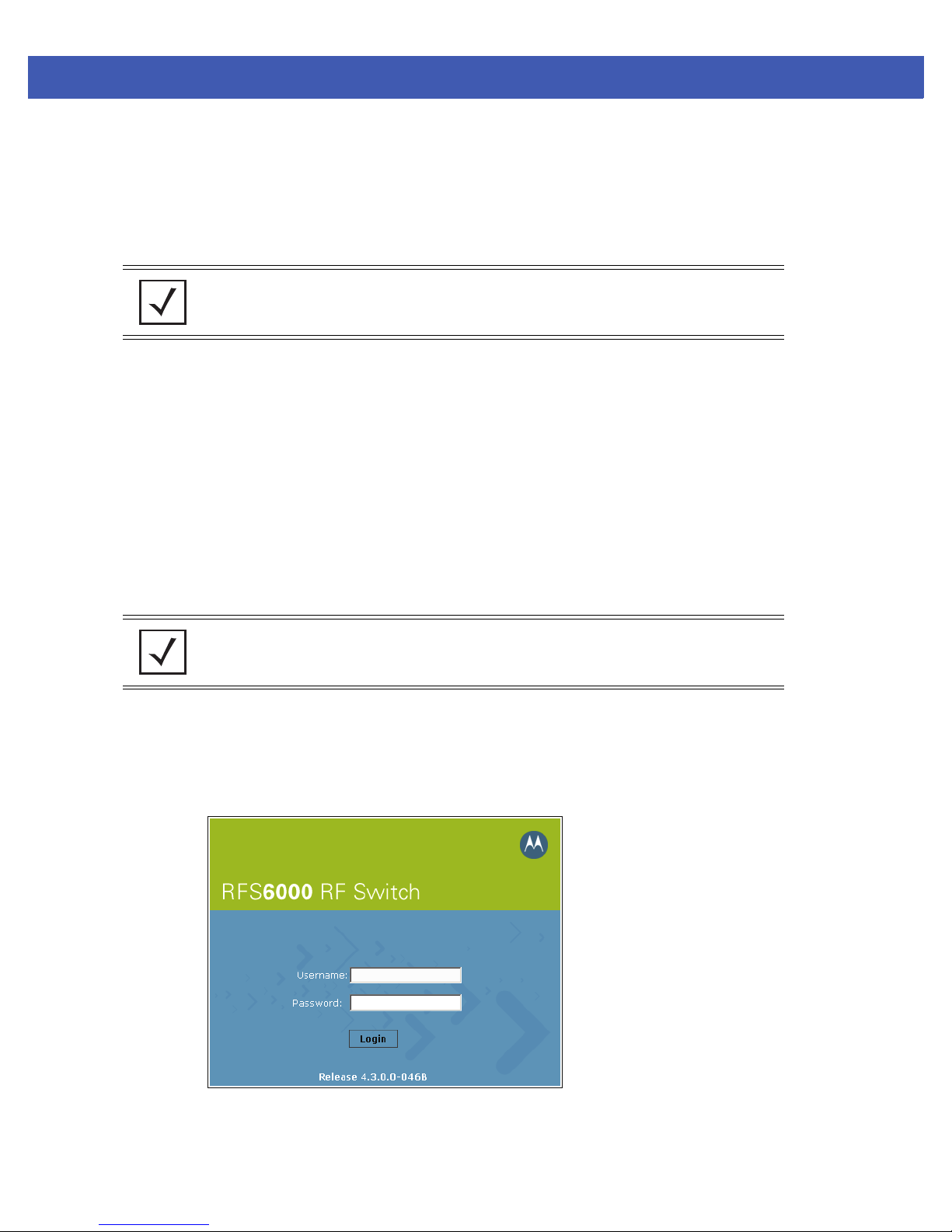
2 - 2 WiNG 4.4 Switch System Reference Guide
2.1 Accessing the Switch Web UI
2.1.1 Web UI Requirements
The switch Web UI is accessed using Internet Explorer version 5.5 (or later) and SUN JRE (Java Runtime Environment) 1.5
(or later). Refer to the Sun Microsystems Web site for information on downloading JRE.
NOTE: To successfully access the switch Web UI through a firewall, UDP port 161 must
be open in order for the switch’s SNMP back end to function.
To prepare Internet Explorer to run the Web UI:
1. Open IE’s Tools > Internet Options panel and select the Advanced tab.
2. Uncheck the following checkboxes:
• Use HTTP 1.1
• Java console enabled (requires restart)
• Java logging enabled
• JIT compiler for virtual enabled (requires restart).
2.1.2 Connecting to the Switch Web UI
To display the Web UI, launch a Web browser on a computer with the capability of accessing the switch.
NOTE: Ensure you have HTTP connectivity to the switch, as HTTP is a required to launch
the switch Web UI from a browser.
To display the switch Web UI:
1. Point the browser to the IP address assigned to the wired Ethernet port (port 2). Specify a secure connection using the
https:// protocol.
The switch login screen displays:
2. Enter the Username admin, and Password superuser. Both are case-sensitive. Click the Login button.
Page 51
Switch Web UI Access and Image Upgrades 2 - 3
NOTE: If using HTTP to login into the switch, you may encounter a Warning screen if a
self-signed certificate has not been created and implemented for the switch. This warning
screen will continue to display on future login attempts until a self-signed certificate is
implemented. Motorola Solutions recommends only using the default certificate for the
first few login attempts until a self-signed certificate can be generated.
NOTE: If your password is lost, there is a means to access the switch, but you are forced
to revert the switch back to its factory default settings and lose your existing
configuration (unless saved to a secure location). Consequently, Motorola Solutions
recommends keeping the password in a secure location so it can be retrieved. For
information on password recovery, see Switch Password Recovery on page 2-4.
Once the Web UI is accessed, the Switch main menu item displays a configuration tab with high-level switch
information. Click the Show Dashboard button to display an overall indicator of switch health. Once the switch is
fully configured, the dashboard is the central display for the user to view the version of firmware running on the switch,
quickly assess the last 5 alarms generated by the switch, view the status of the switch’s Ethernet connections and view
switch CPU and memory utilization statistics.
NOTE: The chapters within this System Reference Guide are arranged to be
complimentary with the main menu items in the menu tree of the switch Web UI. Refer to
this content to configure switch network addressing, security and diagnostics as required.
Page 52

2 - 4 WiNG 4.4 Switch System Reference Guide
2.2 Switch Password Recovery
The access point has a means of restoring its password to its default value. Doing so also reverts the access point’s
security, radio and power management configuration to their default settings. Only an installation professional should
reset the access point’s password and promptly define a new restrictive password.
To contact Motorola Solutions Support in the event of a password reset requirement, go to http://www.motorola.com/
Business/US-EN/Support
CAUTION: Only a qualified installation professional should set or restore the access
point’s radio and power management configuration in the event of a password reset.
!
Page 53

Switch Web UI Access and Image Upgrades 2 - 5
2.3 Upgrading the Switch Image
The switch ships with a factory installed firmware image with the full feature functionality described in this System
Reference Guide. However, Motorola Solutions periodically releases switch firmware that includes enhancements or
resolutions to known issues. Verify your current switch firmware version with the latest version available from the
Motorola Solutions Website before determining if your system requires an upgrade.
Page 54
2 - 6 WiNG 4.4 Switch System Reference Guide
2.4 Auto Installation
The switch auto install function can be configured manually or using a DHCP server. When configuring auto installation
using DHCP, the server requires the definition of a vendor class and four sub-options under option 43 namely:
• Option 186 - defines the tftp/ftp server and ftp username, password information
• Option 187 - defines the firmware path and file name
• Option 188 - defines the config path and file name
• Option 190 - defines the cluster config path and file name.
The individual features (config, cluster-config and image) can be enabled separately using the CLI, SNMP or Web UI. If a
feature is disabled, it is skipped when auto install is triggered.
For manual configuration (where the URLs for the configuration and image files are not supplied by DHCP), the URLs can
be specified using the CLI, SNMP or Applet. Use the CLI to define the expected firmware image version. If the image
version is not specified, the switch will derive it from the header of the firmware image file.
Configuration files are tracked by their MD5 checksum. Configuration files are tracked by their contents. If a file is renamed
its contents remain the same and the file will not be reloaded.
The requested image file version (if any) is checked against the current version before any attempt is made to load it. If
the requested version is the same as the running version, no action is taken. If the image file version (embedded in the file
header) does not match the expected version, no further action is taken. If the version has not been specified, the image
file header is compared to the local version. If they are the same, no action is taken.
NOTE: Once the system has been operating for ten minutes, Auto Install is disabled,
though it may still be reconfigured. This is to prevent the system from attempting to reinstall each time a DHCP lease is renewed.
Configuring Auto Install via the CLI
There are three compulsory and four optional configuration parameters.
The compulsory parameters are:
• configuration upgrade enable
• cluster configuration upgrade enable
• image upgrade enable
Optional (only for the static case):
• configuration file URL
• cluster configuration file URL
• image file URL
• expected image version
To set default to no, and the URLs and the version default to "" (blank):
RF Switch(config)#show autoinstall
feature enabled URL
config no --not-set--
cluster cfg no --not-set--
image no --not-set--
expected image version --not-set--
Page 55

Switch Web UI Access and Image Upgrades 2 - 7
Enables are set using the autoinstall <feature> command:
RF Switch>en
RF Switch#conf t
RF Switch(config)#autoinstall image
RF Switch(config)#autoinstall config
RF Switch(config)#autoinstall cluster-config
After this configuration update, any switch reboot with DHCP enabled on the RON port will trigger an auto install, provided
the DHCP Server is configured with appropriate options.
The "enables" are cleared using the no autoinstall <feature>
URLs and the version string are stored in the configuration file as text and can be cleared using an empty pair of double
quotes to denote the blank string. In the following example, define the three URLs and the expected version of the image
file, then enable all three features for the auto install.
RF Switch(config)#autoinstall config url ftp://ftp:[email protected]/RFSwitch/config
RF Switch(config)#autoinstall cluster-config url ftp://ftp:[email protected]/RFSwitch/
cluster-config
RF Switch(config)#autoinstall image url ftp://ftp:[email protected]/RFSwitch/images/
RFS6000.img
RF Switch(config)#autoinstall image version
RF Switch(config)#autoinstall config
RF Switch(config)#autoinstall cluster-config
RF Switch(config)#autoinstall image
RF Switch(config)#show autoinstall
feature enabled URL
config yes ftp://ftp:[email protected]/RFSwitch/config
cluster cfg yes ftp://ftp:[email protected]/RFSwitch/cluster-config
image yes ftp://ftp:[email protected]/RFSwitch/images/RFS6000.img
expected image version
4.4.
4.4.0.0-XXXXX
Once again, for DHCP option based auto install the URLs is ignored and those passed by DHCP are not stored.
Whenever a string is blank it is shown as --not-set--.
Page 56
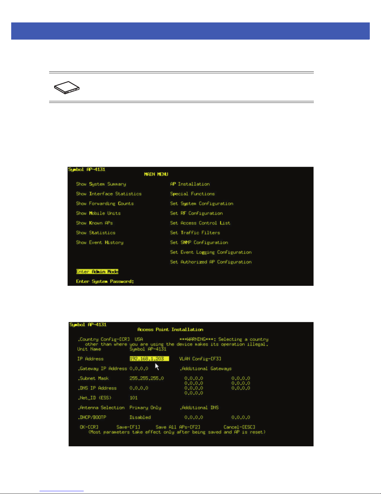
2 - 8 WiNG 4.4 Switch System Reference Guide
2.5 AP-4131 Access Point to Access Port Conversion
Switch Note: AP-4131 Access Point to Access Port Conversion is only available on the
RFS6000 platform.
To convert an AP-4131 “fat” Access Point to a “thin” AP-4131 Access Port you need to load the port conversion version
firmware. Refer to the files available with you Motorola Solutions Website download package.
To convert an AP-4131 Access Point
1. Verify a TFTP server is up and running and the firmware you are going to install is in the root directory of the TFTP server.
2. Log in to the AP-4131 as Admin. The default password is Symbol.
3. Select the AP Installation main menu item.
4. From the IP Address field, enter a new IP address (if required) and select Save-[F1] to save the change. If the IP
address was changed, you will need to reset the AP for the change to be implemented.
5. Reset the AP if you changed the AP's IP address, buy displaying the System Summary and selecting the Reset AP
option. If you reset the AP-4131 you will need to login as Admin again.
Page 57
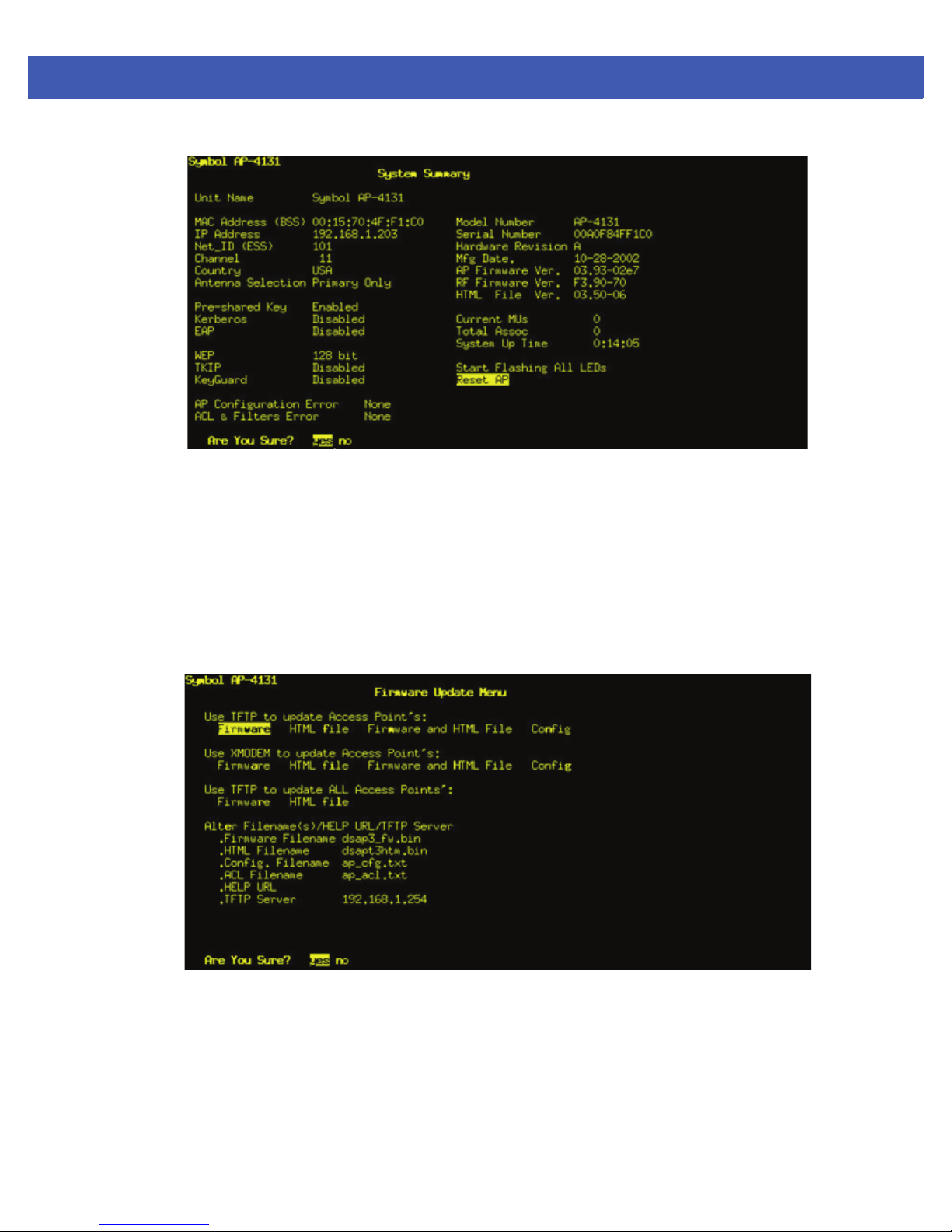
6. Select the Special Functions main menu item.
7. Select the Firmware Update Menu-[F3] menu item
Switch Web UI Access and Image Upgrades 2 - 9
8. Select the Alter Filename(s)/HELP URL/TFTP Server menu item.
a. Confirm that the Firmware File Name is correct, make changes as needed.
b. Enter the IP address of your TFTP server, select enter.
c. Select F1 to save your changes.
9. Select Firmware under the Use TFTP to update Access Point's option.
10.Select yes when asked to confirm.
11.The AP-4131 will now reset, download and install the desired firmware.
12.Once the firmware download is complete, connect the AP-4131 to the PoE switch and the RF Switch The
AP-4131 should adopt and operate as a “thin” Access Port.
Page 58

2 - 10 WiNG 4.4 Switch System Reference Guide
Page 59

CHAPTER 3 SWITCH INFORMATION
This chapter describes the Switch main menu information used to configure the switch. This chapter consists of the
following sections:
• Viewing the Switch Interface
• Viewing Switch Port Information
• Viewing Switch Configurations
• Viewing Switch Firmware Information
• Switch File Management
• Configuring Automatic Updates
• Viewing the Switch Alarm Log
• Viewing Switch Licenses
• How to use the Filter Option
Page 60
3 - 2 WiNG 4.4 Switch System Reference Guide
3.1 Viewing the Switch Interface
The Switch Configuration tab provides high-level system, switch name and address information accessible from one
location. Use this information to assess whether the current firmware version is the most recent and if the number of
licenses available is correct to support the number of radio devices deployed. The values displayed within the screen can
be defined in numerous additional locations throughout the switch applet.
NOTE: The Motorola Solutions RF Management Software is a recommended utility to
plan the deployment of the switch and view its interface statistics once operational in the
field. Motorola Solutions RFMS can help optimize the positioning and configuration of a
switch (and its associated radios) in respect to a WLAN’s MU throughput requirements
and can help detect rogue devices. For more information, refer to the Motorola Solutions
Website.
The switch screen displays two tabs supporting the following configuration activities:
• Setting the Switch Country Code on page 3-2
• Viewing Switch Statistics
NOTE: When the switch’s configuration is successfully updated (using the Web UI), the
effected screen is closed without informing the user their change was successful.
However, if an error were to occur, the error displays within the effected screen’s Status
field and the screen remains displayed. With file transfer operations, the transfer screen
remains open during the transfer and remains open upon completion (with status
displayed within the Status field).
3.1.1 Setting the Switch Country Code
When initially logging into the system, the switch requests that you enter the correct country code for your region. If a
country code is not configured, a warning message will display stating that an incorrect country setting will lead to the
illegal use of the switch. Consequently, selecting the correct country is extremely important. Each country has its own
regulatory restrictions concerning electromagnetic emissions (channel range) and the maximum RF signal strength
transmitted. To ensure compliance with national and local laws, be sure to set the Country value correctly.
NOTE: To ensure proper operation of the Wireless Switch and Access Ports, make sure
the country code set on the Wireless Switch matches the country code set on the Access
Ports or Adaptive APs.
3.1.2 Viewing the Switch Configuration
To view a high-level display of the switch configuration:
1. Select Switch from the main menu tree.
2. Click the Configuration tab.
Page 61
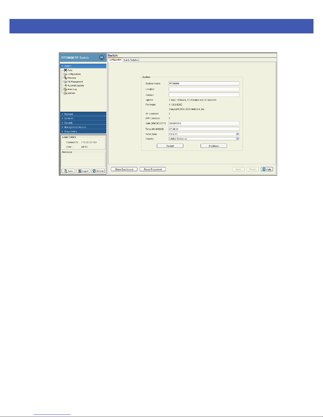
Switch Information 3 - 3
3. Refer the System field to view or define the following information:
System Name Displays the designated system name. Provide a system name serving as a reminder of the user
base the switch supports (engineering, retail, etc.).
Location The Location parameter serves as a reminder of where the switch can be found. Define the
System Name as a specific identifier of the switch’s location. Use the System Name and Location
parameters together to optionally define the switch name by the radio coverage type it supports
and physical location. For example, “second floor engineering.”
Contact Displays a Contact value for system administration and troubleshooting. This name should be
the network administrator responsible for switch operations.
Uptime Displays the current operational time for the device name defined within the System Name field.
Uptime is the cumulative time since the switch was last rebooted or lost power.
Firmware Displays the current firmware version running on the switch. This version should be periodically
compared to the most recent version available on the Motorola Solutions Website, as versions
with increased functionality are periodically released.
AP License Count Displays the number of Access Port licenses currently available for the switch. This value
represents the maximum number of Access Ports the switch is licensed to adopt.
AAP License Count The License Count value displays the number of Adaptive AP licenses installed on this member.
Date (MM/DD/
Displays the day, month and year currently used with the switch.
YYYY)
Time Displays the time of day used by the switch.
Time Zone Use the drop-down menu to specify the time zone used with the switch. Adjusting the time zone
will in turn, cause an adjustment to the time displayed.
Country Use the drop-down menu to specify the correct country of operation. Selecting the country
incorrectly could render your switch as operating illegally.
Page 62
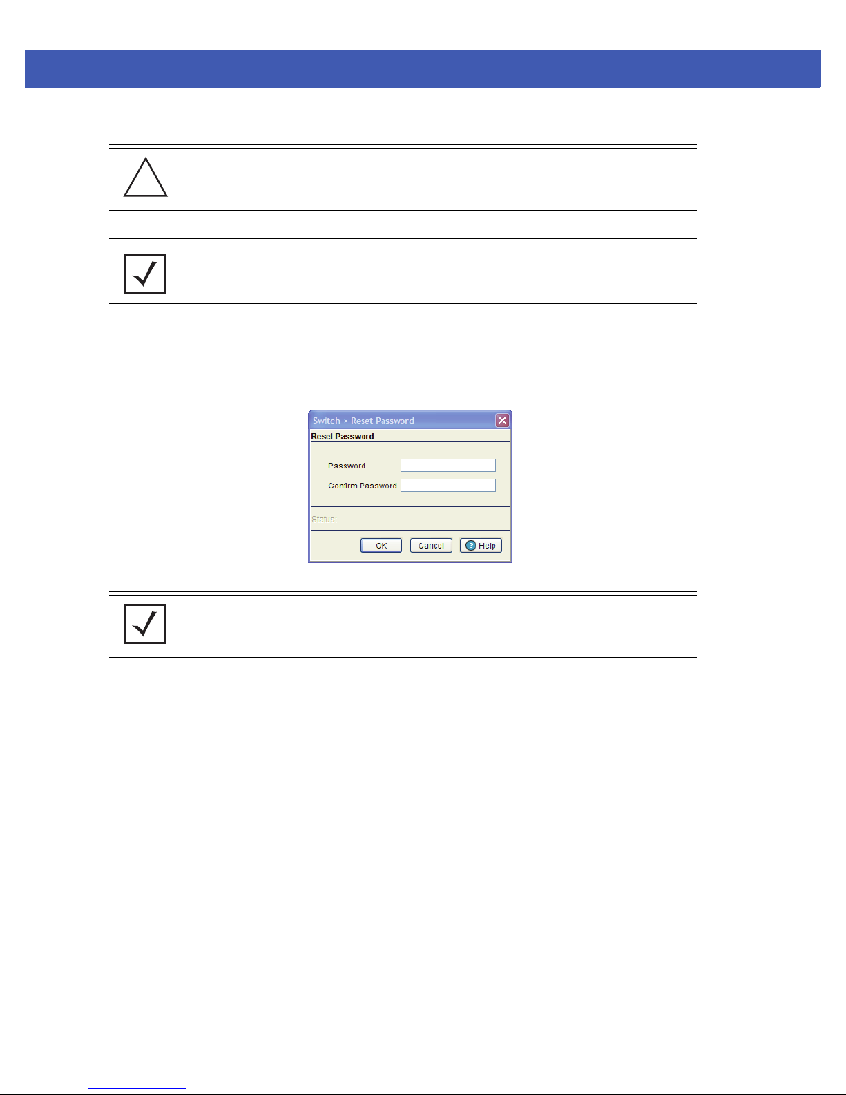
3 - 4 WiNG 4.4 Switch System Reference Guide
4. Click the Restart button to reboot the switch. The switch itself does not include a hardware reset feature.
CAUTION: When rebooting the switch, the Radius Server will also be restarted
regardless of its state before the reboot.
!
5. Click the Shutdown button to shutdown and power off the switch.
NOTE: On the RFS4000, RFS6000, and RFS7000 the shutdown command will shutdown
the switch but the fans on the switch will remain on.
6. Click the Show Dashboard button to display a screen with important indicators of switch health and status. For more
information, see Switch Dashboard Details on page 3-4. Referencing the Details screen is recommended before new
configurations are employed that utilize increased switch bandwidth.
7. Click the Reset Password button to display a screen to reset the password.
Enter the new password within the Password and Confirm Password fields and click OK.
NOTE: When entering a new password for the switch, please note that the password
must be a minimum of 8 characters long.
8. Click the Revert button to undo any changes. The Revert button must be clicked before hitting the Apply button for
any changes to be reverted.
9. Click the Apply button to save the updates (to the Time Zone or Country parameters specifically).
3.1.3 Switch Dashboard Details
Each Motorola Solutions RF Switch platform contains a dashboard which represents a high-level graphical overview of
central switch processes and hardware. When logging into the switch, the dashboard should be the first place you go to
assess overall switch performance and any potential performance issues.
Click the Show Dashboard button (within the Switch screen’s Configuration tab) to display the current health of the
switch
Page 63
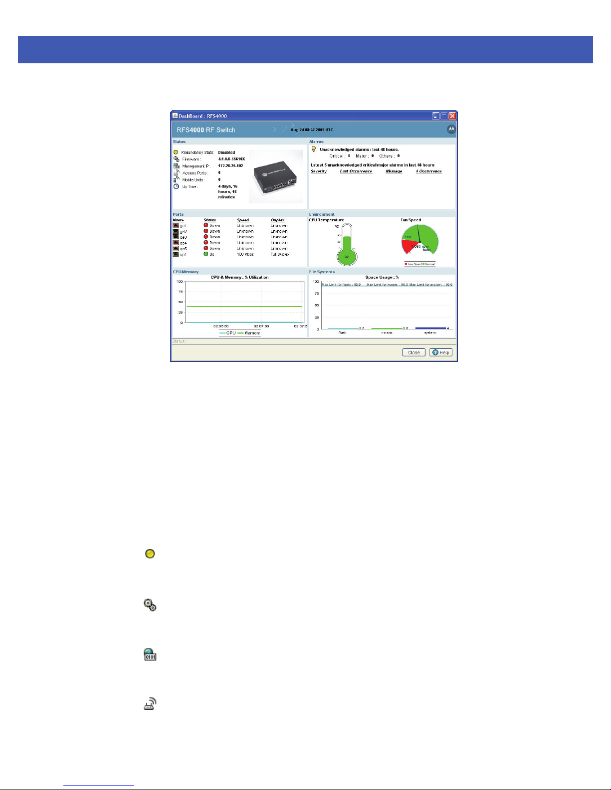
3.1.3.1 RFS4000 Switch Dashboard
Switch Information 3 - 5
The Dashboard screen displays the current health of the switch and is divided into fields representing the following
important diagnostics:
•Alarms
• Ports
• Environment
• CPU/Memory
• File Systems
Apart from the sections mentioned above, it also displays the following status:
Redundancy State
Firmware
Displays the Redundancy State of the switch. The status can be either Enabled or Disabled.
• Enabled - Defined a green state.
• Disabled - Defined by a yellow state.
Displays the Firmware version of the current software running on the wireless switch.
Management IP
Displays the Management IP address of the switch.
Access Ports
Displays the total number of Access Ports adopted by the switch.
Page 64

3 - 6 WiNG 4.4 Switch System Reference Guide
Mobile Units Displays the total number of MUs associated with the switch.
Up Time Displays the actual switch uptime. The Uptime is the current operational time of the device
defined within the System Name field. Uptime is the cumulative time since the switch was
last rebooted or lost power.
1. Refer to the Alarms field for details of all the unacknowledged alarms generated during the past 48 hours. The alarms
are classified as:
• Critical — Denoted by a red indicator. These alarms warrant immediate attention.
• Major — Denoted by a yellow indicator. These alarms warrant attention.
• Others — Denoted by a blue indicator.
The alarms field also displays details (in a tabular format) of the 5 most recent unacknowledged critical/major alarms
raised during the past 48 hours. The table displays the following details:
Severity
Last Occurrence
Message
# Occurrences
Displays the severity of the alarm. It can be either Critical or Major.
Displays the time when the alarm was reported.
Displays the message associated with the alarm.
Displays the number of times during the past 48 hours such an alarm was generated.
2. Refer to the Ports field for link, speed and duplex status of each physical port on the switch’s front panel. It displays
the following details in a tabular format:
Name
Status
Speed
Duplex
Displays the name of the port (ge1-8, me1 or up1)
Displays the status of the port, either— Up or Down
Displays the speed at which the port transmits or receives data.
Displays the status of the port, either— Full Duplex or Unknown.
3. The Environment section displays the CPU temperature. It displays the valid threshold range set by the user.
4. The CPU/Memory section displays the free memory available with the RAM.
5. The File Systems section displays the free file system available for:
•flash
•nvram
• system
Page 65
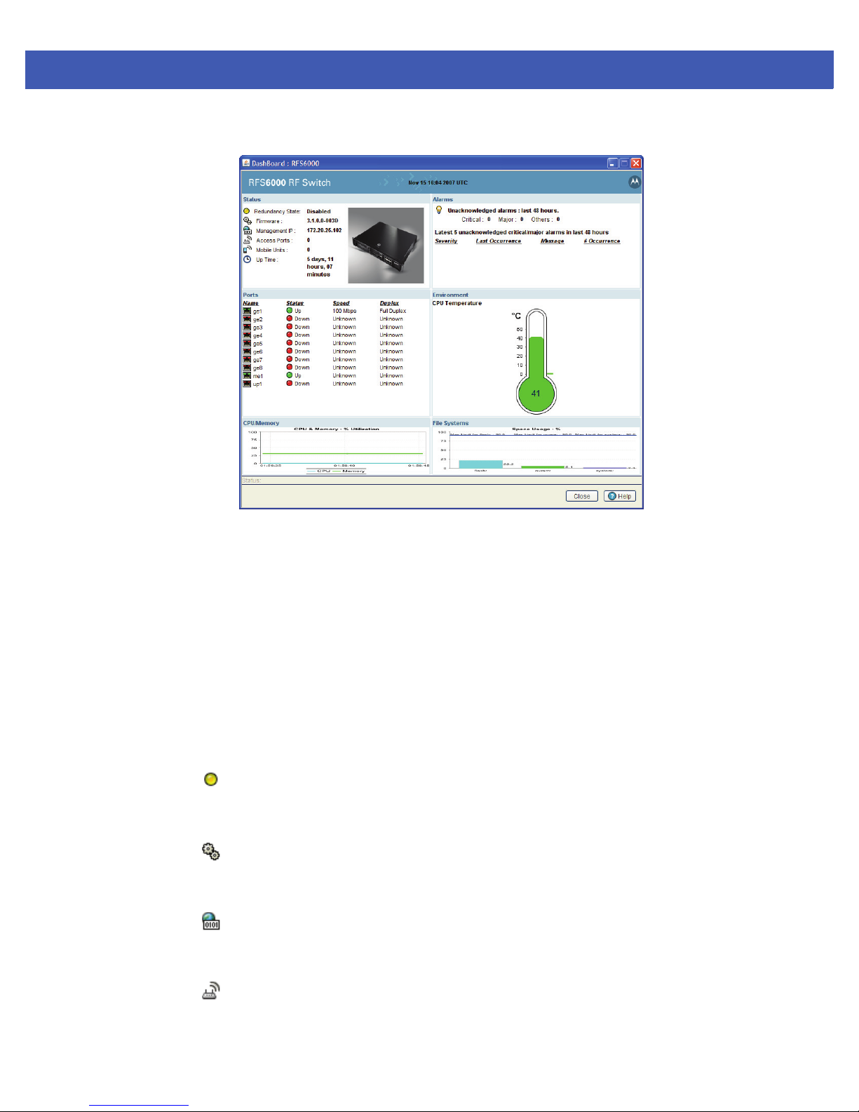
3.1.3.2 RFS6000 Switch Dashboard
Switch Information 3 - 7
The Dashboard screen displays the current health of the switch and is divided into fields representing the following
important diagnostics:
•Alarms
• Ports
• Environment
• CPU/Memory
• File Systems
Apart from the sections mentioned above, it also displays the following status:
Redundancy State
Firmware
Displays the Redundancy State of the switch. The status can be either Enabled or Disabled.
• Enabled - Defined a green state.
• Disabled - Defined by a yellow state.
Displays the Firmware version of the current software running on the wireless switch.
Management IP
Displays the Management IP address of the switch.
Access Ports
Displays the total number of Access Ports adopted by the switch.
Page 66

3 - 8 WiNG 4.4 Switch System Reference Guide
Mobile Units Displays the total number of MUs associated with the switch.
Up Time Displays the actual switch uptime. The Uptime is the current operational time of the device
defined within the System Name field. Uptime is the cumulative time since the switch was
last rebooted or lost power.
1. Refer to the Alarms field for details of all the unacknowledged alarms generated during the past 48 hours. The alarms
are classified as:
• Critical — Denoted by a red indicator. These alarms warrant immediate attention.
• Major — Denoted by a yellow indicator. These alarms warrant attention.
• Others — Denoted by a blue indicator.
The alarms field also displays details (in a tabular format) of the 5 most recent unacknowledged critical/major alarms
raised during the past 48 hours. The table displays the following details:
Severity
Last Occurrence
Message
# Occurrences
Displays the severity of the alarm. It can be either Critical or Major.
Displays the time when the alarm was reported.
Displays the message associated with the alarm.
Displays the number of times during the past 48 hours such an alarm was generated.
2. Refer to the Ports field for link, speed and duplex status of each physical port on the switch’s front panel. It displays
the following details in a tabular format:
Name
Status
Speed
Duplex
Displays the name of the port (ge1-8, me1 or up1)
Displays the status of the port, either— Up or Down
Displays the speed at which the port transmits or receives data.
Displays the status of the port, either— Full Duplex or Unknown.
3. The Environment section displays the CPU temperature. It displays the valid threshold range set by the user.
4. The CPU/Memory section displays the free memory available with the RAM.
5. The File Systems section displays the free file system available for:
•flash
•nvram
• system
Page 67
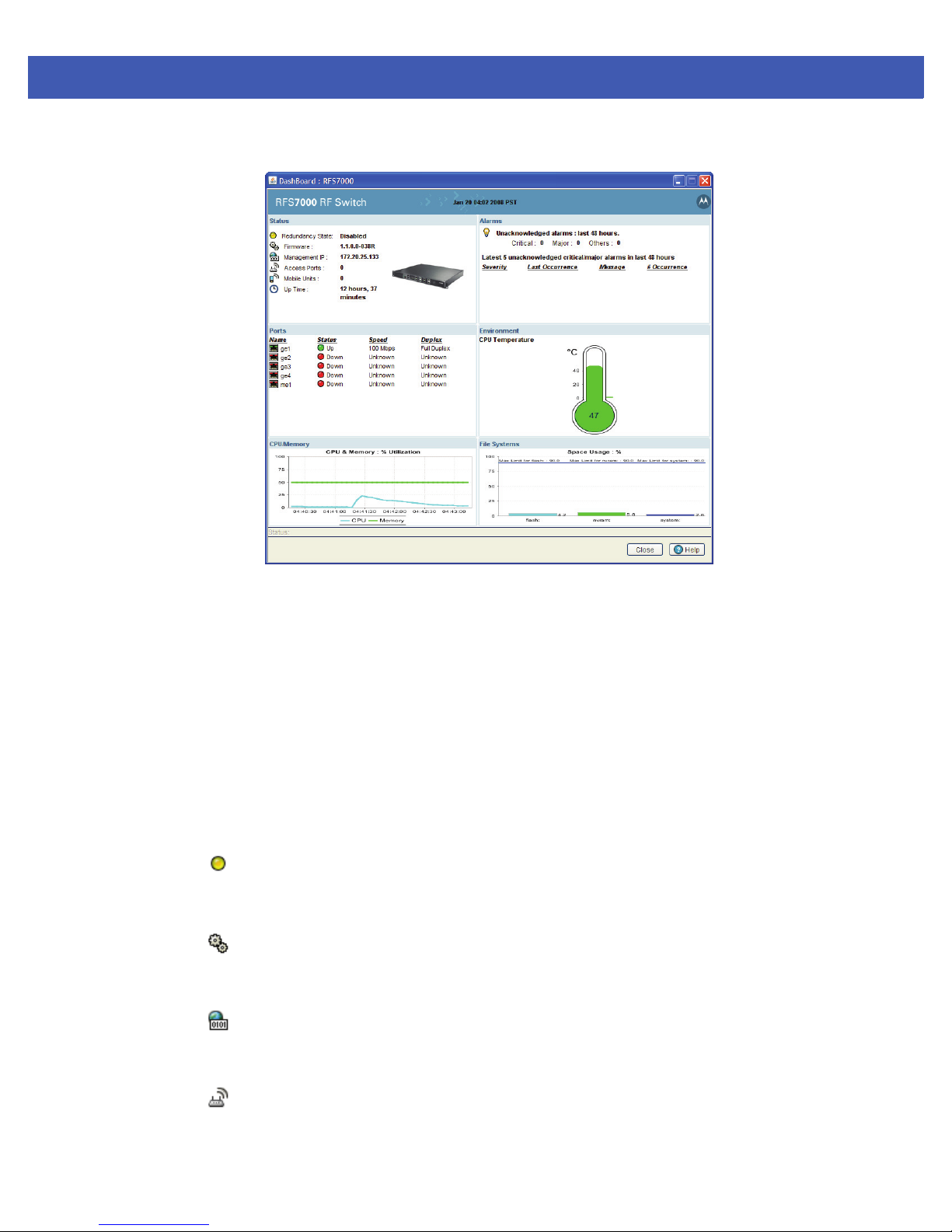
3.1.3.3 RFS7000 Switch Dashboard
Switch Information 3 - 9
The Dashboard screen displays the current health of the switch and is divided into fields representing the following
important diagnostics:
•Alarms
• Ports
• Environment
• CPU/Memory
• File Systems
Apart from the sections mentioned above, it also displays the following status:
Redundancy State Displays the Redundancy State of the switch. The status can be either Enabled or Disabled.
• Enabled - Defined by a green state.
• Disabled - Defined by a yellow state.
Firmware
Displays the Firmware version of the current software running on the wireless switch.
Management IP
Displays the Management IP address of the switch.
Access Ports
Displays the total number of Access Ports adopted by the switch.
Page 68

3 - 10 WiNG 4.4 Switch System Reference Guide
Mobile Units Displays the total number of MUs associated with the switch.
Up Time Displays the actual switch uptime. The Uptime is the current operational time of the device
defined within the System Name field. Uptime is the cumulative time since the switch was last
rebooted or lost power.
1. Refer to the Alarms field for details of all the unacknowledged alarms generated during the past 48 hours. The alarms
are classified as:
• Critical — Denoted by a red indicator. These alarms warrant immediate attention.
• Major — Denoted by a yellow indicator. These alarms warrant attention.
• Others — Denoted by a blue indicator.
The alarms field also displays details (in a tabular format) of the 5 most recent unacknowledged critical/major alarms
raised during the past 48 hours. The table displays the following details:
Severity
Last Occurrence
Message
# Occurrences
Displays the severity of the alarm. It can be either Critical or Major.
Displays the time when the alarm was reported.
Displays the message associated with the alarm.
Displays the number of times during the past 48 hours such an alarm was generated.
2. Refer to the Ports field for link, speed and duplex status of each physical port on the switch’s front panel. It displays
the following details in a tabular format:
Name
Status
Speed
Duplex
Displays the name of the port (ge1, ge2, ge3, ge4 and me1).
Displays the status of the port, either— Up or Down
Displays the speed at which the port transmits or receives data.
Displays the status of the port, either— Full Duplex or Unknown.
3. The Environment section displays the CPU temperature. It displays the valid threshold range set by the user.
4. The CPU/Memory section displays the free memory available with the RAM.
5. The File Systems section displays the free file system available for:
•flash
•nvram
• system
Page 69
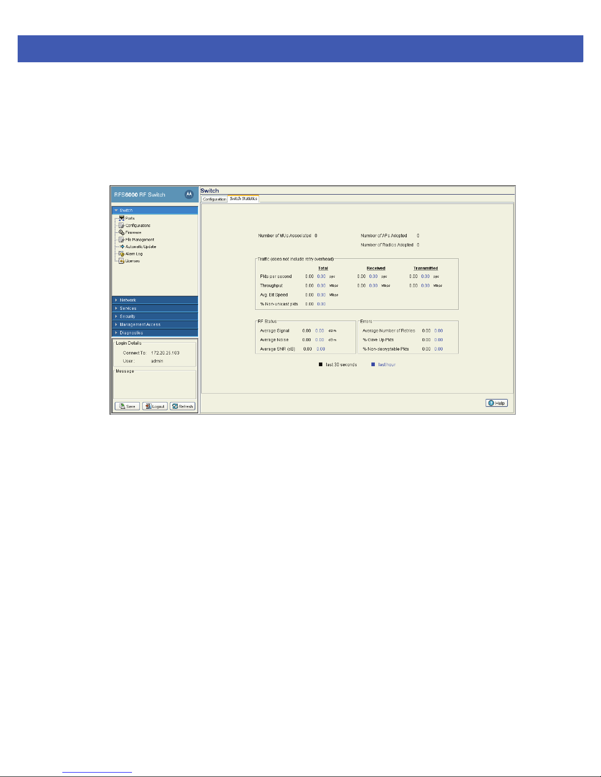
3.1.4 Viewing Switch Statistics
The Switch Statistics tab displays an overview of the recent network traffic and RF status for the switch.
To display the Switch Statistics tab:
1. Select Switch from the main menu tree.
2. Click the Switch Statistics tab at the top of the Switch screen.
Switch Information 3 - 11
3. Refer to the Switch Statistics field for the following read-only information about associated MUs:
Number of MUs
Associated
Number of APs
Adopted
Number of Radios
Adopted
4. Refer to the Traffic field to assess network traffic for associated APs and radios:
Pkts per second Displays the packet transmission rate for received and transmitted packets over last 30 seconds
Throughput Displays the traffic throughput for packets received, packets transmitted, and total packets over
Displays the total number of MUs currently associated to the switch.
Displays the total number of Access Ports currently adopted by the switch.
Displays the total number of radios currently adopted by the switch.
and 1 hour.
last 30 seconds and 1 hour.
Page 70

3 - 12 WiNG 4.4 Switch System Reference Guide
Avg. Bit Speed Displays the average bit speed for the switch over last 30 seconds and 1 hour. Use the average
bit speed value to help determine overall network speeds and troubleshoot network congestion.
% Non-unicast
pkts
Displays the percentage of non-unicast packets seen (received & transmitted) by the switch over
last 30 seconds and 1 hour. Non-unicast traffic includes both multicast and broadcast traffic.
Broadcast, multicast, and flooded packets are sent over the air at the slowest rate on every radio
in the WLAN and therefore have a much larger airtime utilization than unicast packets and a
greater chance of causing collisions.
5. The RF Status section displays the following read-only RF radio signal information for associated APs and radios:
Avg. Signal Displays the average signal strength for MUs associated with the switch over the last 30 seconds
and 1 hour. Typically, the higher the signal, the closer the MU.
Avg. Noise Displays the average RF noise for all MUs associated with the selected WLAN. MU noise for the
last 30 seconds is displayed in black and the number in blue represents MU noise for the last hour.
If MU noise is excessive, consider moving the MU closer to the Access Port, or in area with less
conflicting network traffic. Excessive noise may also be an indication of network interference.
Avg. SNR Displays the average Signal to Noise Ratio (SNR) for all MUs associated with the switch. The
Signal to Noise Ratio is an indication of overall RF performance on the wireless network.
6. Refer to the Errors field for read-only packet error and loss information for associated Access Ports and radios:
Average Number of
Retries
Displays the average number of retries for all MUs associated with the switch. The number in
black represents average retries for the last 30 seconds and the number in blue represents
average retries for the last hour.
If the Average Number of Retries starts increasing, this indicates that MUs are not getting a good
link back to the AP.
% Gave Up Pkts Displays the percentage of packets which the switch gave up on for all MUs associated with the
switch. The number in black represents this statistic for the last 30 seconds and the number in
blue represents this statistic for the last hour.
If this field displays a non-zero number it indicates bad links causing packets to the MUs.
% Non-decryptable
Pkts
Displays the percentage of undecryptable packets for all MUs associated with the switch. The
number in black represents undecryptable pkts for the last 30 seconds and the number in blue
represents undecryptable pkts for the last hour.
If this field displays a non-zero number it can indicate outside intrusion into the network or an MU
using incorrect cryptography such as a a misconfigured static key.
Page 71

3.2 Viewing Switch Port Information
The Port screen displays configuration, runtime status, and statistics of the ports on the switch.
Switch Note: The ports available vary by switch platform.
RFS6000: ge1, ge2, ge3, ge4, ge5, ge6, ge7, ge8, me1, up1
RFS7000: ge1, ge2, ge3, ge4, me1
RFS4000: ge1, ge2, ge3, ge4, ge5, up1
The port types are defined as follows:
GE# GE ports are available on the RFS6000 and RFS7000 platforms. GE ports on the RFS4000 and
RFS6000 are RJ-45 which support 10/100/1000Mbps. GE ports on the RFS7000 can be RJ-45 or
fiber ports which support 10/100/1000Mbps.
ME# ME ports are available on the RFS6000 and RFS7000 platforms. ME ports are out-of-band
management ports which can be used to manage the switch via CLI or Web UI even when the
other ports on the switch are unreachable.
UP# An UP port is available on the RFS4000 and RFS6000 platform only. This port is used to connect
the switch to the backbone network. The UP port on the switch supports either RJ-45 or fiber. The
UP port is the preferred way to connect to the backbone as it has a non-blocking 1gbps connection
unlike the ge ports.
Switch Information 3 - 13
The Port screen contains three tabs supporting the following port assessment activities:
• Viewing the Port Configuration
• Viewing the Ports Runtime Status
• Reviewing Port Statistics
3.2.1 Viewing the Port Configuration
The Configuration tab displays the current configuration for the switch ports. Use the port configuration information to
determine whether an existing port configuration can be used as is or requires modification for use within the switch
managed network.
To view configuration details for the uplink and downlink ports:
1. Select Switch > Ports from the main menu tree.
Page 72
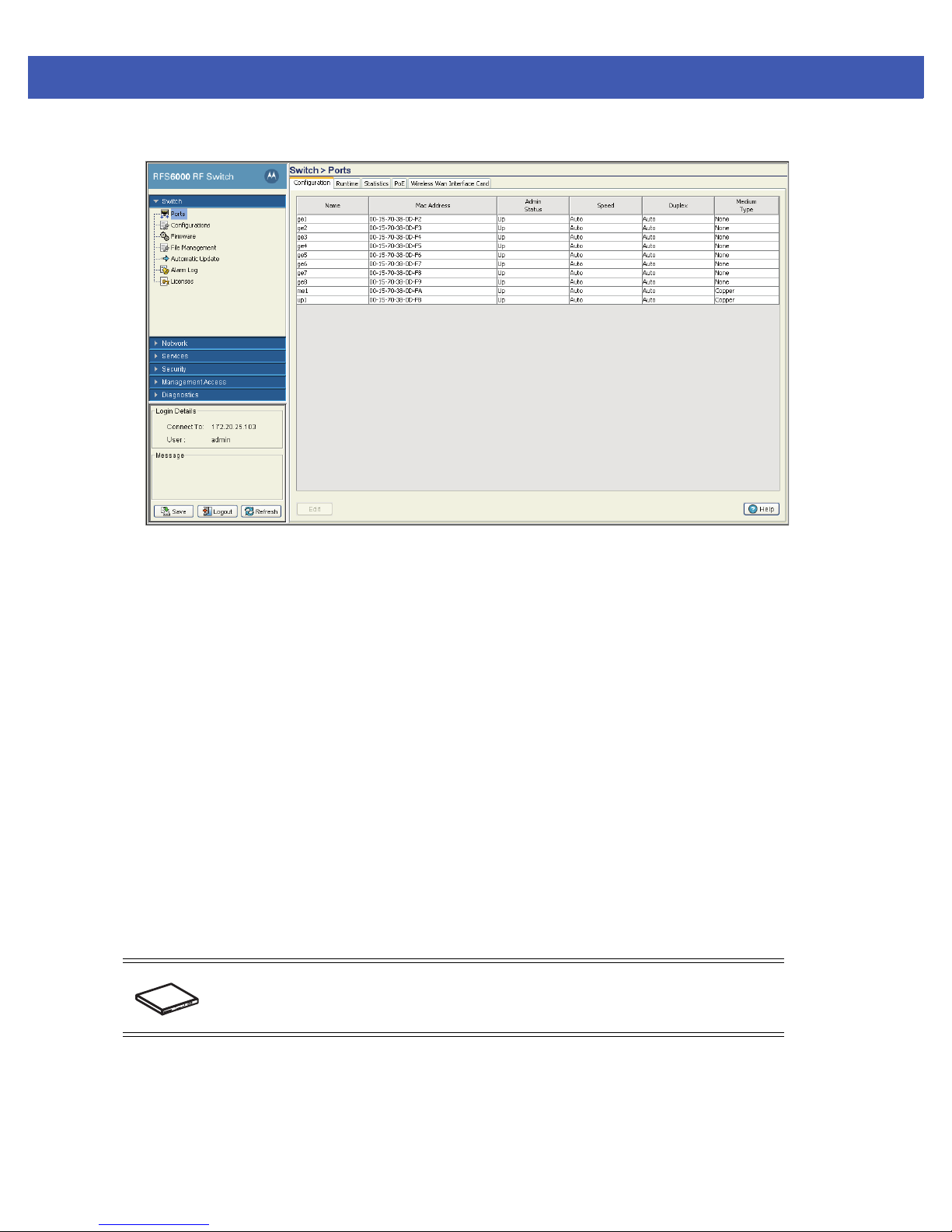
3 - 14 WiNG 4.4 Switch System Reference Guide
2. Select the Configuration tab to display the following read-only information:
Name Displays the current port name. The port names available vary by switch.
RFS6000: ge1, ge2, ge3, ge4, ge5, ge6, ge7, ge8, me1, up1, wan
RFS7000: ge1, ge2, ge3, ge4, me1
RFS4000: ge1, ge2, ge3, ge4, ge5. up1
Aggregation Membership
The Aggregation Membership value displays the channel group the port is a member of.
(RFS7000, RFS4000)
MAC Address Displays the port’s MAC Address. This value is read-only, set at the factory and cannot be
modified.
Admin Status Displays whether the port is currently Up or Down.
Speed Displays the current speed of the data transmitted and received over the port.
Duplex Displays the port as either half or full duplex.
Medium Type The Medium Type value displays the physical connection type of the port. Medium types
are:
• Copper: Used on RJ-45 Ethernet Ports
• Optical: Used on Fiber Optic Gigabit Ethernet Ports
Switch Note: On a RFS7000, the MAC address for the me1 port changes when the switch
firmware is updated to the 1.3 version. This addresses an issue where the switch MAC
address and ge1 interface shared the same MAC address in previous versions.
3. Select a port and click the Edit button to modify the port configuration. For additional information, see Editing the Port
Configuration on page 3-15.
Page 73
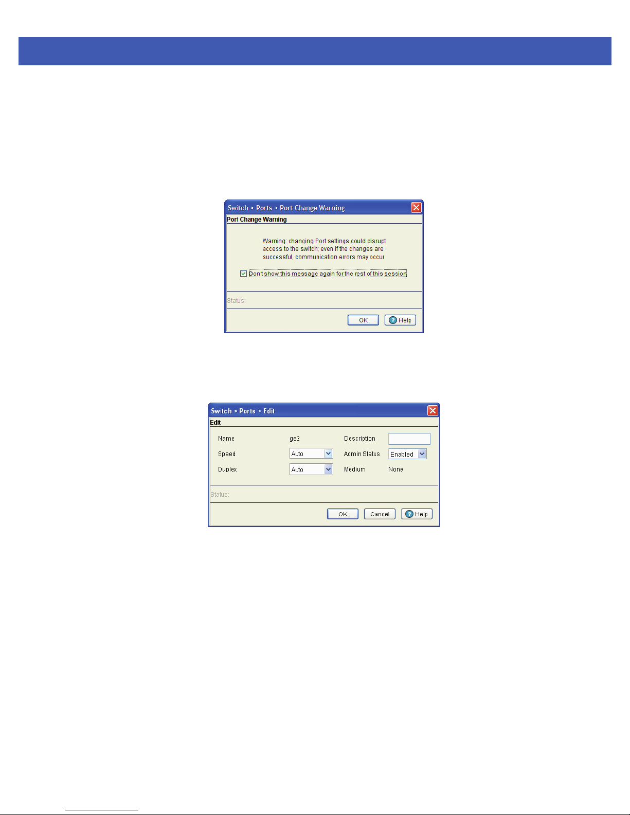
3.2.1.1 Editing the Port Configuration
To modify the port configuration:
1. Select a port from the table displayed within the Configuration screen.
2. Click the Edit button.
A Port Change Warning screen displays, stating any change to the port setting could disrupt access to the switch.
Communication errors may occur even if modifications made are successful.
Switch Information 3 - 15
3. Click the OK button to continue.
Optionally, select the Don’t show this message again for the rest of the session checkbox to disable the pop-up.
4. Use the Edit screen to modify the following port configurations for the selected port.
Page 74

3 - 16 WiNG 4.4 Switch System Reference Guide
Name
Speed
Displays the read-only name assigned to the port.
Select the speed at which the port can receive and transmit the data. Select from the following
range:
•10 Mbps
• 100 Mbps
• 1000 Mbps
•Auto
Duplex Modify the duplex status by selecting one of the following options:
•Half
•Full
•Auto
Channel Group Optionally, set the Channel Group defined for the port. The switch bundles individual Ethernet
links (over the selected channel) into a single logical link that provides bandwidth between the
switch and another switch or host. The port speed used is dependant on the Duplex value selected
(full, half, or auto). If a segment within a channel fails, traffic previously carried over the failed link
is routed to the remaining segments within the channel. A trap is sent upon a failure identifying
the switch, channel, and failed link.
Description Enter a brief description for the port. The description should reflect the port’s intended function to
differentiate it from others with similar configurations.
Admin Status Either Enable (activate) or Disable (shutdown) the admin status of the port.
Medium Displays the current (read-only) connection medium used by this port.
Read-only details about the port’s cabling connection also display within the Edit screen. This information should be
used to determine the configuration defined for this port.
5. Click the OK button to commit the changes made to the port configurations.
6. Click Cancel to disregard any changes and revert back to the last saved configuration.
3.2.2 Viewing the Ports Runtime Status
The Runtime tab displays read-only runtime configuration for uplink and downlink ports.
To view the runtime configuration details of the uplink and downlink ports:
1. Select Switch > Ports from the main menu tree.
Page 75
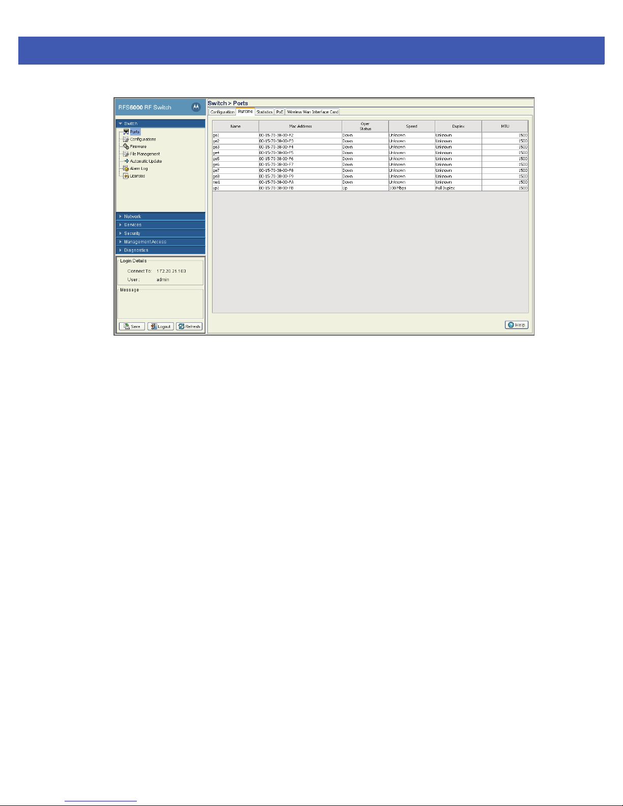
Switch Information 3 - 17
2. Select the Runtime tab to display the following read-only information:
Name Displays the port’s current name.
MAC Address Displays the port’s MAC Address. This value is read-only, set at the factory and cannot be
modified.
Oper Status Displays the link status of the port. The port status can be either Up or Down.
Speed Displays the current speed of the data transmitted and received over the port.
Duplex Displays the port as either half duplex, full duplex, or Unknown.
MTU Displays the maximum transmission unit (MTU) setting configured on the port. The MTU value
represents the largest packet size that can be sent over a link. 10/100 Ethernet ports have a
maximum MTU setting of 1500.
3.2.3 Reviewing Port Statistics
The Statistics tab displays read-only statistics for ethernet ports. Use this information to assess if configuration changes
are required to improve network performance.
To view the runtime configuration details of the switch ports:
1. Select Switch > Ports from the main menu tree.
Page 76
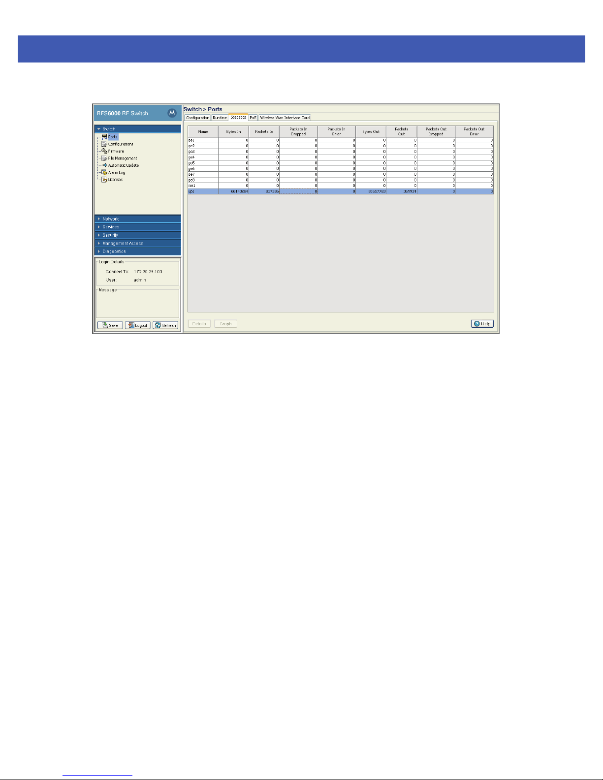
3 - 18 WiNG 4.4 Switch System Reference Guide
2. Select the Statistics tab.
3. Refer to the Statistics tab to display the following read-only information:
Name Defines the port name. The port names available vary by switch.
RFS6000: ge1, ge2, ge3, ge4, ge5, ge6, ge7, ge8, me1, up1, wan
RFS7000: ge1, ge2, ge3, ge4, me1
RFS4000: ge1, ge2, ge3, ge4, ge5, up1
Bytes In Displays the total number of bytes received by the port.
Packets In Displays the total number of packets received by the port.
Packets In Dropped Displays the number of packets dropped by the port. If the number appears excessive, a different
port could be required.
Packets In Error Displays the number of erroneous packets received by the port. If the number appears excessive,
try using a different port and see if the problem persists.
Bytes Out Displays the total number of bytes transmitted by the port.
Packets Out Displays the total number of packets transmitted by the port. A low value could be an indication
of a network problem.
Packets Out
Dropped
Displays the total number of packets dropped during transmission. A high value may be an
indication of network throughput issues.
Packets Out Error Displays the total number of erroneous transmitted packets.
4. Select a port and click on the Details button to see the detailed port statistics. For more information, refer to Detailed
Port Statistics on page 3-19.
5. Select a port and click on the Graph button to view the port statistics in a graphical format. For more information, refer
to Viewing the Port Statistics Graph on page 3-20.
Page 77
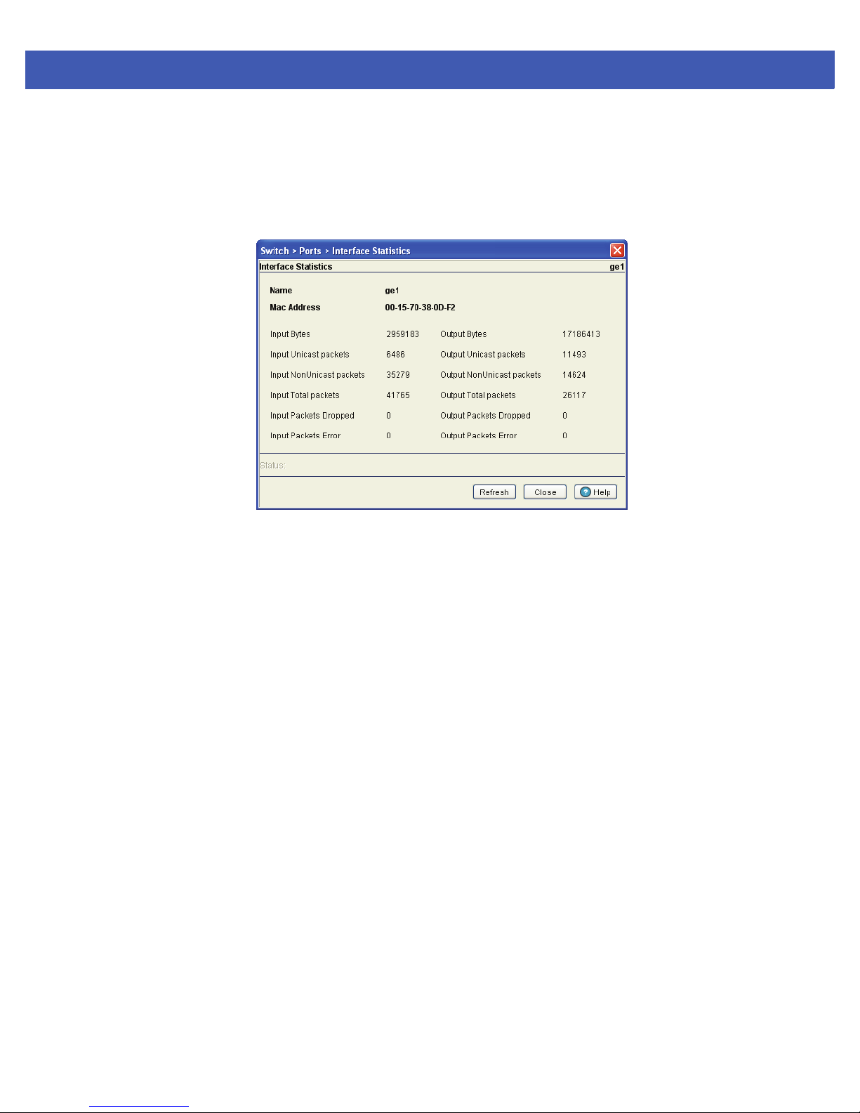
3.2.3.1 Detailed Port Statistics
To view detailed statistics for a port:
1. Select a port from the table displayed within the Statistics screen.
2. Click the Details button.
Switch Information 3 - 19
3. The Interface Statistics screen displays. This screen displays the following statistics for the selected port:
Name Displays the port name.
MAC Address Displays physical address information associated with the interface. This address is read-only
(hard-coded at the factory) and cannot be modified.
Input Bytes Displays the number of bytes received on the interface.
Input Unicast
Packets
Input NonUnicast
Packets
Displays the number of unicast packets (packets directed towards the interface) received on the
interface.
Displays the number of NonUnicast Packets (Multicast and Broadcast Packets) received on the
interface.
Input Total Packets Displays the total number of packets received on the interface.
Input Packets
Dropped
Displays the number of received packets dropped by the interface by the input Queue of the
hardware unit /software module associated with the VLAN. Packets are dropped when the input
Queue is full or unable to process incoming traffic.
Input Packets Error Displays the number of packets with errors received on the interface. Input Packet Errors are input
errors due to: no buffer space/ignored packets due to broadcast storms, packets larger than
maximum packet size, framing errors, input rate exceeding the receiver's date handling rate, or
cyclic redundancy check errors. In all of these cases, an error is reported and logged.
Output Bytes Displays the number of bytes transmitted from the interface.
Output Unicast
Packets
Displays the number of unicast packets (packets directed towards a single destination address)
transmitted from the interface.
Page 78

3 - 20 WiNG 4.4 Switch System Reference Guide
Output NonUnicast
Displays the number of unicast packets transmitted from the interface.
Packets
Output Total
Displays the total number of packets transmitted from the interface.
Packets
Output Packets
Dropped
Displays the number of transmitted packets dropped from the interface. Output Packets Dropped
are packets dropped when the output queue of the device associated with the interface is
saturated.
Output Packets
Error
Displays the number of transmitted packets with errors. Output Packet Errors are the sum of all
the output packet errors, malformed packets, and misaligned packets received.
4. The Status is the current state of the requests made from the applet. Requests are any “SET/GET” operation from the
applet. The Status field displays error messages if something goes wrong in the transaction between the applet and
the switch.
5. Click on the Refresh button to refresh the port statistics.
6. Click on the Close button to exit out of the screen.
3.2.3.2 Viewing the Port Statistics Graph
The switch continuously collects data for port statistics. Even when the port statistics graph is closed, data is still tallied.
Periodically display the port statistics graph for assessing the latest information.
To view a detailed graph for a port:
1. Select a port from the table displayed in the Statistics screen.
2. Click the Graph button.
The Interface Statistics screen displays for the selected port. The screen provides the option to view the following:
• Input Bytes
• Input Pkts Dropped
• Output Pkts Total
Page 79
• Output Pkts Error
• Input Pkts Total
• Input Pkts Error
• Output Pkts NUCast
• Input Pkts NUCast
• Output Bytes
• Output Pkts Dropped
3. Display any of the above by selecting the checkbox associated with it.
NOTE: You are not allowed to select (display) more than four parameters at any given
time.
4. Click on the Close button to exit out of the screen.
3.2.4 Power over Ethernet (PoE)
Switch Information 3 - 21
Switch Note: Power over Ethernet is supported on the RFS6000 and RFS4000 switches.
The RFS6000 switch supports 802.3af Power over Ethernet (PoE) on each of its eight ge ports. The PoE screen allows users
to monitor the power consumption of the ports and configure power usage limits and priorities for each of the ge ports.
To view the PoE configuration:
1. Select Switch > Ports from the main menu tree.
Page 80

3 - 22 WiNG 4.4 Switch System Reference Guide
2. Select the PoE tab
Switch Note: The PoE screen is available on the RF6000 and RFS4000 switches. The
RFS7000 switch does not have Power over Ethernet on any ports and will not display the
PoE tab.
The PoE Global Configuration section displays the following power information.
Power Budget Displays the total watts available for Power over Ethernet on the switch.
Power
Displays the total watts in use by Power over Ethernet on the switch.
Consumption
Power Usage
Threshold for
Specify a percentage of power usage as the threshold before the switch sends an SNMP trap. The
percentage is a percentage of the total power budget of the switch.
Sending Trap
If you have modified the
Power Usage Threshold for Sending Trap value, click the Apply button to save the changes.
Port Displays the port name for each of the PoE capable ports.
PoE Displays the PoE status of each PoE capable port. Status will display Up when PoE is
available on the port and Down when PoE is unavailable on the port.
Class Displays the IEEE Power Classification for each port:
Class Number Maximum Power Required from Switch
0 (unknown) 15.4 Watts
1 4 Watts
2 7 Watts
3 15.4 Watts
Page 81
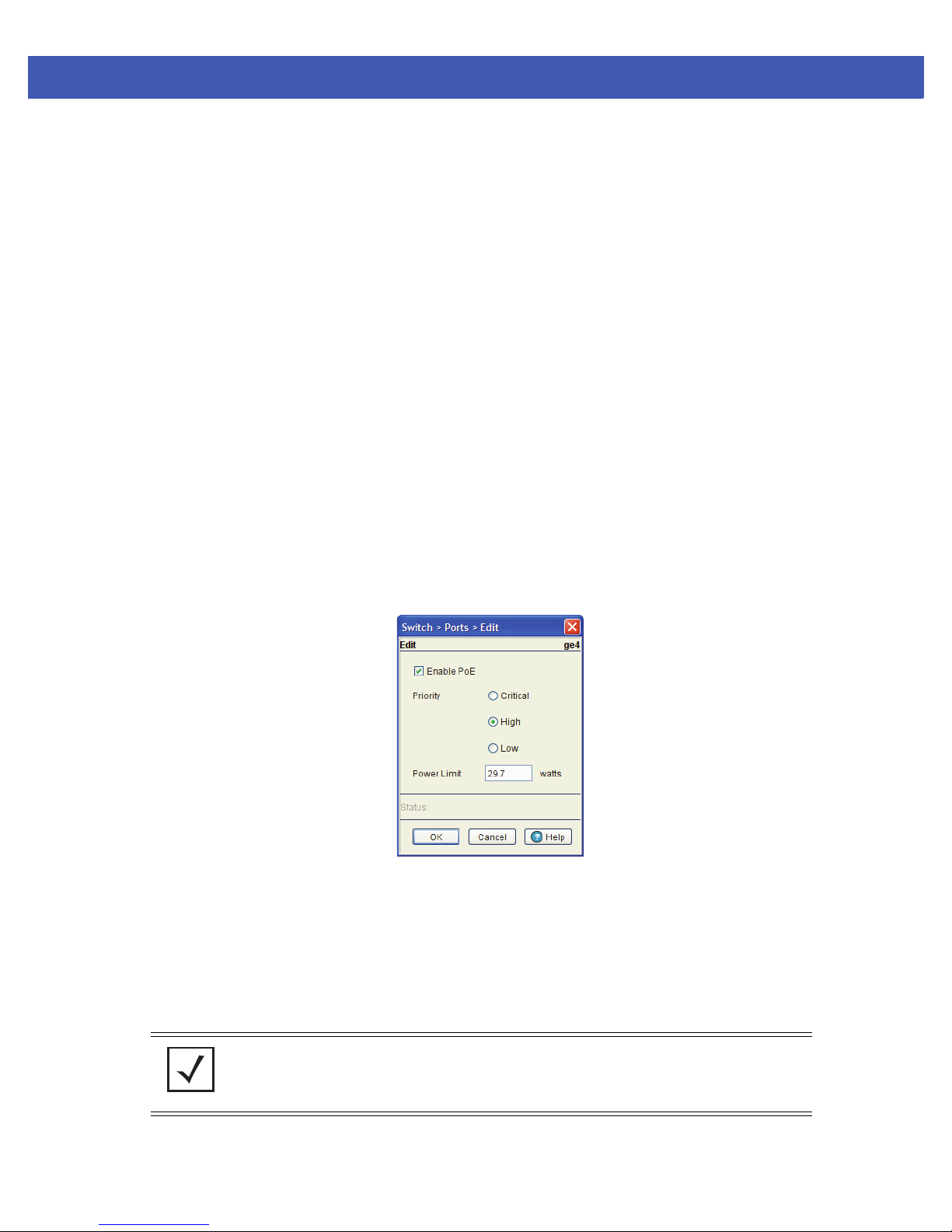
Priority Displays the priority mode for each of the PoE ports.
The priority options are:
Limit (watts) Displays the power limit in watts for each of the PoE ports. The maximum power limit per
port is 36 watts.
Power (watts) Displays each PoE ports power usage in watts.
Voltage (volts) Displays each PoE ports voltage usage in volts.
Current (mA) Displays each PoE ports current usage in milliamps.
Status Displays the operational status for each PoE port. Ports can be either On or Off.
3.2.5 Editing Port PoE Settings
To modify the PoE settings for a port:
Switch Information 3 - 23
• Critical
•High
•Low
1. Select a port to edit from the table.
2. Click the Edit button.
The PoE Edit screen shows the port PoE status, Priority, and Power Limit.
3. Check the Enable PoE checkbox to configure the selected port to use Power over Ethernet. To disable PoE on a port,
uncheck this box.
4. Select the Priority level for PoE on this port. The Priority level is used in cases where the switch’s PoE power
consumption exceeds the available power. When this happens, ports with higher Priority levels will be given
precedence over those with a lower Priority level.
5. Set the Power Limit (in watts) for this port’s PoE usage. Setting the Power Limit places a cap on the maximum
amount of power which can be drawn from the selected port.
NOTE: Power limits and power budgets are based on worst case operating conditions to
deliver power at the level requested. The worst case operating conditions assume the
switch is operating at its maximum operating temperature and at a maximum cable
length. As a result power levels may be between 5% and 10.5% over requested level.
6. Click OK to save and add the changes to the running configuration and close the dialog.
Page 82
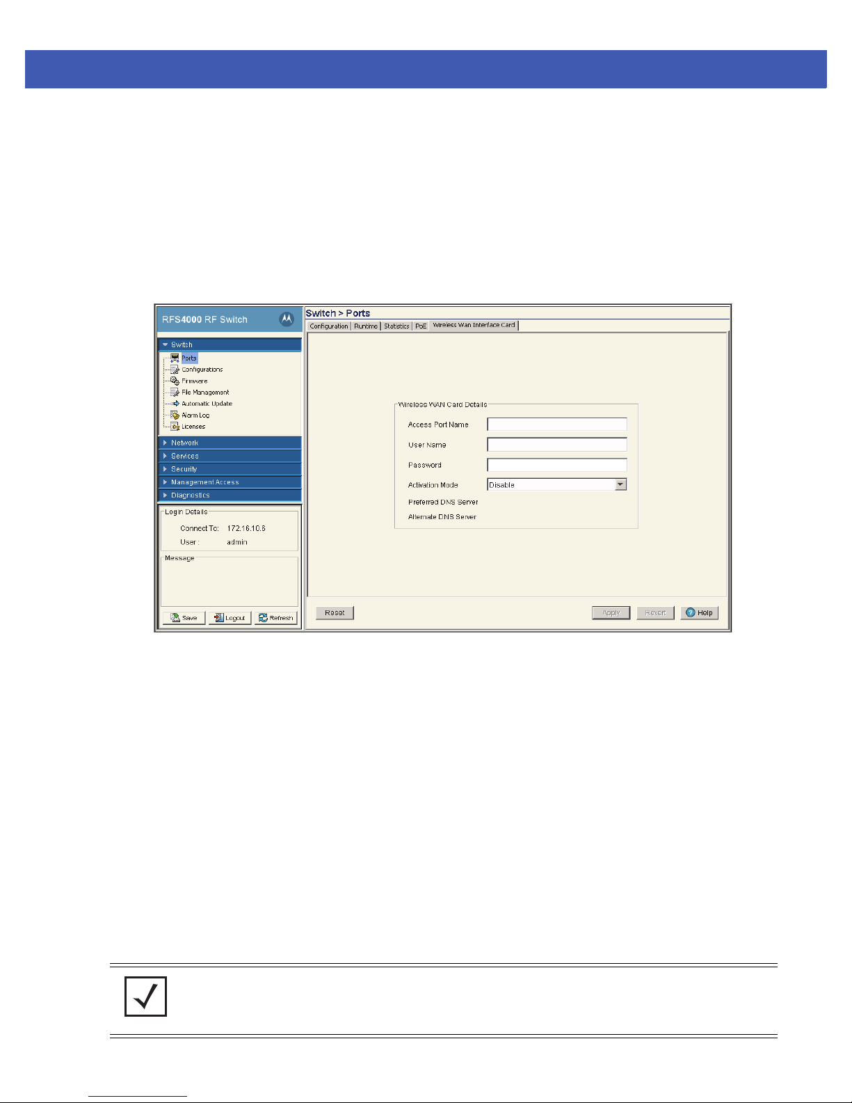
3 - 24 WiNG 4.4 Switch System Reference Guide
3.2.6 Configuring WAN Interface Cards
The RFS6000 switch supports 3G Wireless WAN cards using the ExpressCard slot. In order to use a 3G Wireless WAN card
with the switch, it must first be initialized on a laptop. For activation and initialization information, refer to the instructions
included with the card. If your Wireless WAN Interface card service provider makes use of a PIN number for access to the
network, disable the PIN number before using the card with the switch.
To configure a Wireless WAN Interface card:
1. Select Switch > Ports from the main menu tree.
2. Select the Wireless WAN Interface Card tab.
3. Enter the following parameters to configure a WAN Interface Card:.
Access Port Name If your Wireless WAN service provider requires you to specify an Access Port Name, enter that
value here. The range is <0-25> and default value is 0
User Name Enter the User Name configured for use with the Wireless WAN Interface Card. The string range
is <0-32> and default value is 0
Password Enter the Password associated with the above User Name for the Wireless WAN Interface
Card.The string range is <0-30> and default value is 0
Activation Mode Select Enable from the pull-down menu to enable the Wireless WAN Interface Card. Select
Disable from the pull-down menu to turn off the Wireless WAN Interface Card.
Preferred DNS
Server
Alternate DNS
Server
NOTE: To use a 3G Wireless WAN card with the switch, it must first be initialized on a laptop. For
activation and initialization information, refer to the instructions included with the WAN card. If your
Wireless WAN Interface card service provider makes use of a PIN number for access to the network,
disable the PIN number before using the card with the switch.
Displays the primary/preferred DNS Server provided by the Wireless WAN service provider.
Displays the secondary/alternate DNS Server provided by the Wireless WAN service provider.
Page 83

Switch Information 3 - 25
4. To reset the WAN Interface card configuration, click the Reset button and the configuration fields will be cleared.
Page 84
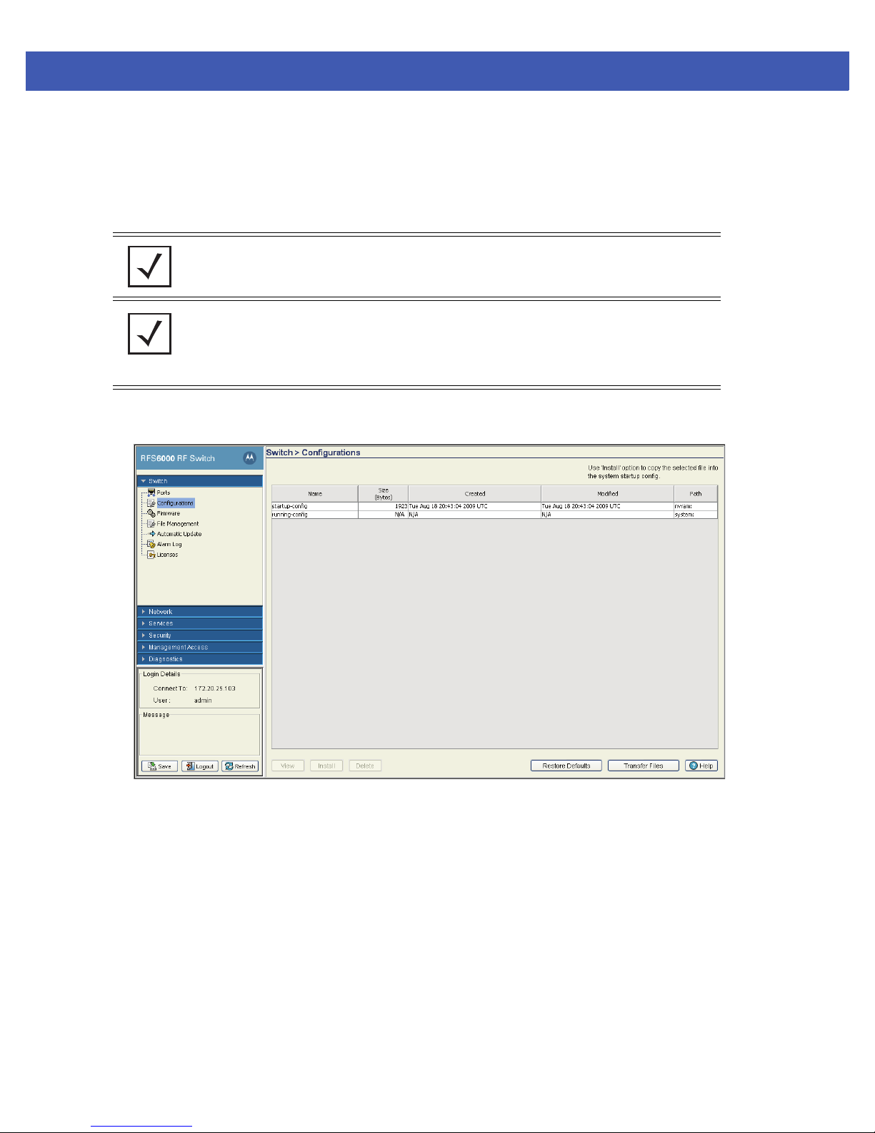
3 - 26 WiNG 4.4 Switch System Reference Guide
3.3 Viewing Switch Configurations
Use the Configurations screen to review the configuration files available to the switch. The details of each configuration
can be viewed individually. Optionally, edit the file to modify its name or use the file as the switch startup configuration.
A file can be deleted from the list of available configurations or transferred to a user specified location.
NOTE: To view the entire switch configuration using SNMP, the switch CLI provides a
better medium to review the entire switch configuration.
NOTE: The Motorola Solutions RF Management Software is a recommended utility to
plan the deployment of the switch and view its configuration once operational in the field.
Motorola Solutions RFMS can help optimize the positioning and configuration of a switch
(and its associated radios) in respect to a WLAN’s MU throughput requirements and can
help detect rogue devices. For more information, refer to the Motorola Solutions Website.
To view the Configuration files available to the switch:
1. Select Switch > Configurations from the main menu tree.
The following information is displayed in tabular format. Configuration files (with the exception of startup-config and
running-config) can be edited, viewed in detail, or deleted.
Name Displays the name of each existing configuration file.
Size (Bytes) Displays the size (in bytes) of each available configuration file.
Created Displays the date and time each configuration file was created. Use this information as a baseline
for troubleshooting problems by comparing event log data with configuration file creation data.
Modified Displays the date and time each configuration file was last modified. Compare this column
against the Created column to discern which files were modified and make informed decisions
whether existing files should be further modified or deleted.
Path Displays the path (location) to the configuration file.
Page 85
Switch Information 3 - 27
2. To view the contents of a config file in detail, select a config file by selecting a row from the table and click the View
button. For more information, see Viewing the Detailed Contents of a Config File on page 3-27.
3. Select a configuration (other than the start-up-config or running config) and click the Install button to install the file
on the switch and replace the existing startup-config file.
If a file (for example, sample-config) is selected, a message displays stating, “When sample-config is installed, it will
replace start-up config. Are you sure you want to install sample-config.” Click Ye s to continue.
NOTE: Selecting either the startup-config or running-config does not enable the Edit
button. A different configuration must be available to enable the Edit function for the
purposes of replacing the existing startup-config.
4. To permanently remove a file from the list of configurations available to the switch, select a configuration file from the
table and click the Delete button.
If startup-config is deleted, a prompt displays stating the default switch startup-config will automatically take its place.
The switch running-config cannot be deleted.
5. To restore the system’s default configuration and revert back to factory default, click the Restore Defaults button.
NOTE: After setting the switch to revert to factory default settings, the system must be
rebooted before the default settings take effect. When this occurs, the switch IP address
may change.
6. Click the Transfer Files button to move a target configuration file to a secure location for later use. For more
information, see Transferring a Config File on page 3-28.
3.3.1 Viewing the Detailed Contents of a Config File
The View screen displays the entire contents of a configuration file. Motorola Solutions recommends a file be reviewed
carefully before it is selected from the Config Files screen for edit or designation as the switch startup configuration.
1. Select a configuration file from the Configuration screen by highlighting the file.
2. Click the View button to see the contents of the selected configuration file.
Page 86
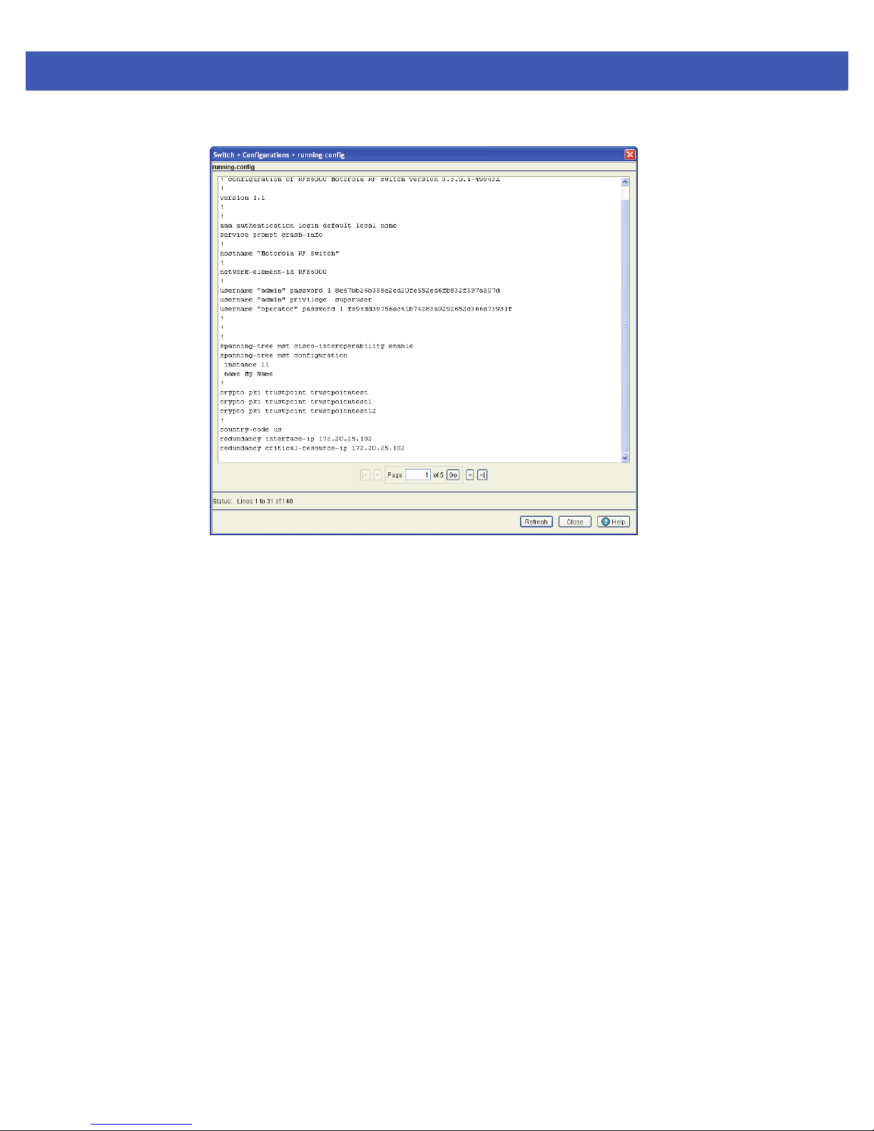
3 - 28 WiNG 4.4 Switch System Reference Guide
Use the up and down navigation facilities on the right-hand side of the screen to view the entire page.
3. The Page parameter displays the portion of the configuration file in the main viewing area.
The total number of pages in the file are displayed to the right of the current page. The total number of lines in the file
display in the Status field at the bottom of the screen.
Scroll to corresponding pages as required to view the entire contents of the file. To navigate to a specific page, enter
the page number in the text area (next to Page item) and click on the Go button. The source parameter differs
depending on the source selected.
4. Refer to the Status field for the current state of the requests made from the applet. Requests are any “SET/GET”
operation from the applet. The Status field displays error messages if something goes wrong in the transaction
between the applet and the switch.
5. Click the Refresh button to get the most recent updated version of the configuration file.
6. Click Close to close the dialog without committing updates to the running configuration.
3.3.2 Transferring a Config File
Transfer a configuration file to and from the switch using the Tr an sf er screen. Transferring the switch configuration is
recommended to keep viable configurations available in a secure location. The following file transfer configurations are
possible:
• switch to switch, server, or local disk
• server to switch
• local disk to switch
To transfer the contents of a configuration file:
1. Click the Transfer Files button on the bottom of the Configuration screen.
Page 87
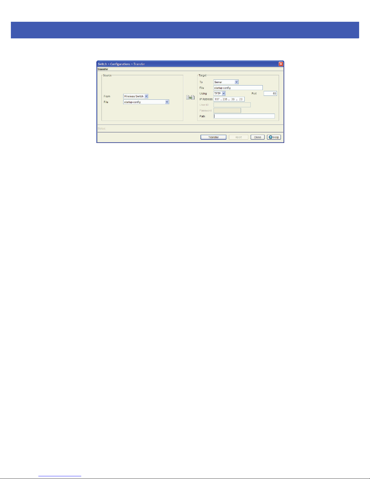
Switch Information 3 - 29
2. Refer to the Source field to define the location and address information for the source config file.
From Select the location representing the source file’s current location using the From drop-down
menu. Options include Server, Local Disk, and Switch.
File Specify a source file for the file transfer. If the switch is selected, the file used at startup
automatically displays within the File parameter.
Using Refer to the Using drop down-menu to configure whether the log file transfer is conducted using
FTP or TFTP. FTP transfers require a valid user ID and password.
IP Address Enter the IP Address of the server or system receiving the source configuration. Ensure the IP
address is valid or risk jeopardizing the success of the file transfer.
User ID Enter the User ID credentials required to transfer the configuration file from a FTP server.
Password Enter the Password required to send the configuration file from an FTP server.
Path Specify an appropriate Path name to the target directory on the local system disk or server. The
Target options are different depending on the target selected.
3. Refer to the Ta rg et field to specify the details of the target file.
To Use the To drop-down menu to define the location of the configuration file. Options include the
switch (default location), external server, or local disk.
File Use the File field to specify a target file for the file transfer. Use the File Browser icon to search
attached files systems for target file location.
4. Refer to the Status field for the current state of the requests made from the applet. Requests are any “SET/GET”
operation from the applet. The Status field displays error messages if something goes wrong in the transaction
between the applet and the switch.
5. Click the Tra ns fe r button when ready to move the target file to the specified location. Repeat the process as necessary
to move each desired configuration file to the specified location.
6. Click the Abort button to cancel the file transfer process before it is complete.
7. Click the Close button to exit the Transfer screen and return to the Config Files screen. Once a file is transferred, there
is nothing else to be saved within the Transfer screen.
Page 88
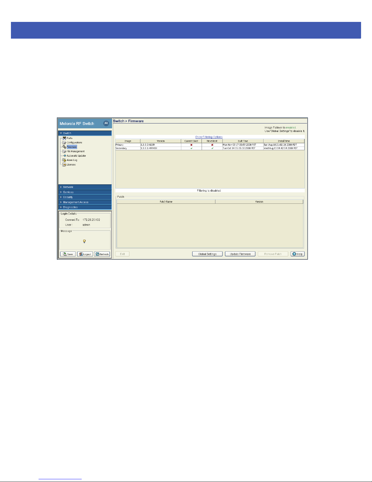
3 - 30 WiNG 4.4 Switch System Reference Guide
3.4 Viewing Switch Firmware Information
The switch can store (retain) two software versions (primary and secondary). Information supporting the two versions
displays within the Firmware screen. The Version column displays the version string. The Build Time is the date and
time each version was generated. Install represents the date and time the upgrade was performed. Next Boot indicates
which version should be used on the next reboot. The Next Boot version should match the Running Version, unless the
system has failed over to another version.
To view the firmware files available to the switch:
1. Select Switch > Firmware from the main menu tree.
2. Refer to the following information displayed within the Firmware screen:
Image Displays whether a firmware image is the primary image or a secondary image. The primary image
is typically the image loaded when the switch boots.
Version Displays a unique alphanumeric version for each firmware file listed.
Current Boot A check mark within this column designates this version as the version used by the switch the last
time it was booted. An “X” in this column means this version was not used the last time the
switch was booted.
Next Boot A check mark within this column designates this version as the version to be used the next time
the switch is booted. An “X” in this column means this version will not be used the next time the
switch is booted. To change the boot designation, highlight an image and click the Edit button.
Built Time Displays the time the version was created (built). Do not confuse the Built Time with the time the
firmware was last loaded on the switch.
Install Time The Install Time is the time this version was loaded with on the switch. Periodically review this
information to assess the relevance of older files.
3. Refer to the Patch field for a listing of the patches available to the switch. The name and version of each patch file is
displayed. Each patch file has an associated .txt file designation. The text file describes nuances associated with the
file that may make it optimal for use with the switch.
Page 89
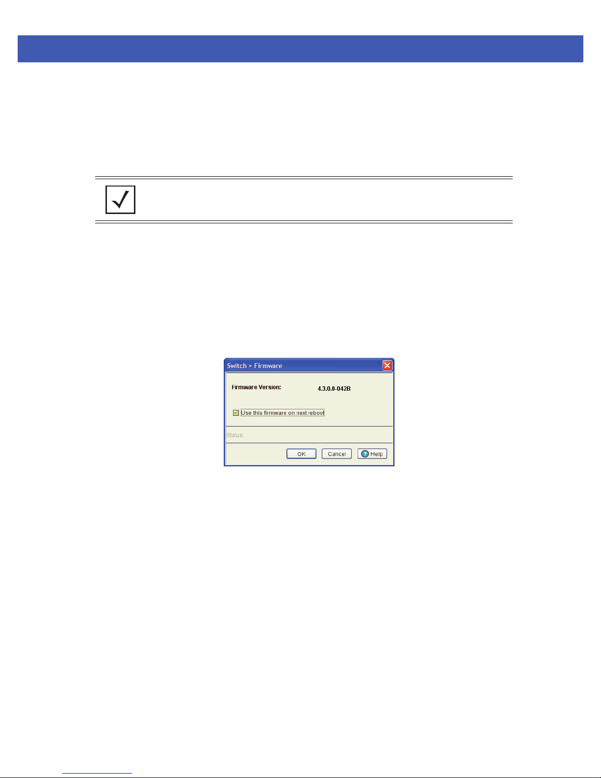
4. Select an existing firmware version and click the Edit button to change the firmware version used when the switch is
booted next. For more information, see Editing the Switch Firmware on page 3-31.
5. Click on the Global Settings button to specify a firmware version for use with the failover image. For more
information, see Enabling Global Settings for the Image Failover on page 3-31.
6. Click on the Update Firmware button to update the firmware file loaded onto the switch. For more information, see
Updating the Switch Firmware on page 3-32.
NOTE: To apply a patch to the switch, follow the same instructions for updating the
switch’s firmware.
7. To remove a patch, select it from amongst those displayed within the Patch field and click the Remove Patch button.
3.4.1 Editing the Switch Firmware
The Edit screen enables the user to select a firmware file and designate it as the version used the next time the switch is
booted.
1. Select the primary firmware image from the Firmware screen.
2. Click the Edit button.
Switch Information 3 - 31
The Firmware screen displays the current firmware version and whether this version is used for the next reboot.
3. Select the checkbox to use this version on the next boot of the switch.
4. To edit the secondary image, select the secondary image, click the Edit button, and select the Use this firmware on
next reboot checkbox.
This firmware version will now be invoked after the next reboot of the switch.
5. Refer to the Status field for the current state of the requests made from the applet. Requests are any “SET/GET”
operation from the applet. The Status field displays error messages if something goes wrong in the transaction
between the applet and the switch.
6. Click the OK button to commit the changes made and exit the screen.
3.4.2 Enabling Global Settings for the Image Failover
Use the Global Settings screen to specify a firmware version for use with the failover image.
1. Select an image from the table in the Firmware screen.
2. Click the Global Settings button.
Page 90
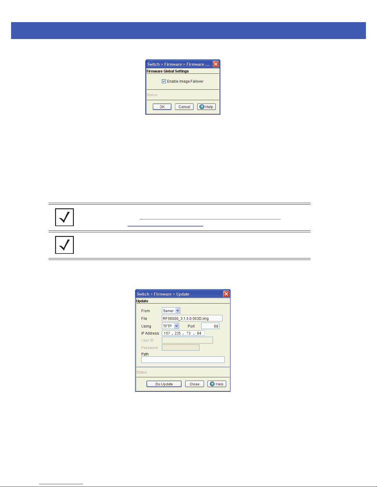
3 - 32 WiNG 4.4 Switch System Reference Guide
3. Select the Enable Image Failover checkbox to load an alternative firmware version if the WLAN module fails to load
the selected version successfully after 2 reboot attempts.
4. Refer to the Status field for the current state of the requests made from the applet. Requests are any “SET/GET”
operation from the applet. The Status field displays error messages if something goes wrong in the transaction
between the applet and the switch.
5. Click OK to save and add the changes to the running configuration and close the dialog.
3.4.3 Updating the Switch Firmware
Use the Update screen to update the firmware version currently used by the switch.
NOTE: When performing a firmware update using the switch CLI, use the following
syntax (specific to FTP)
If using TFTP, use tftp://ipaddress/path/filename.
NOTE: When performing a firmware update using FTP, be sure that TCP port 21 is open
between the switch and the FTP server where the firmware file is located.
1. Select an image from the table in the Firmware screen.
2. Click the Update Firmware button.
ftp://username:password@ipaddress:port/path/filename.
3. Use the From drop-down menu to specify the location from which the file is sent.
4. Enter the name of the file containing the firmware update in the File text field.
This is the file that will append the file currently in use.
5. From the Using drop down menu, select either FTP or TFTP as a medium to update the firmware.
a. Use FTP to get the firmware update from a File Transfer Protocol (FTP) server. A user account must be established
on the FTP server specified for the firmware update.
b. Use TFTP to get the firmware update from a Trivial File Transfer Protocol (TFTP) server.
Page 91
Switch Information 3 - 33
c. Use HTTP to get the firmware update from a Hyper Text Transfer Protocol (HTTP) server.
d. Use SFTP to get the firmware update from a Secure File Transfer Protocol (SFTP) server. A user account
must be established on the SFTP server specified for the firmware update.
Switch Note: On the RFS7000, users can also transfer firmware files using USB or Compact Flash. On the RFS6000, users can also transfer firmware files using USB. On the
RFS4000, users can also transfer firmware files using USB or PCI Express card.
6. Enter the IP address for the FTP or TFTP server in the IP address field.
7. Enter the username for FTP server login in the User ID field.
8. Enter the password for FTP server login in the Password field.
9. Enter the complete file path for the file that contains the firmware update in the Path field.
10.Click the Do Update button to initiate the update.
A warning prompt displays. Upon confirming the firmware update, the switch reboots and completes the firmware
update.
CAUTION: When restarting or rebooting the switch, the Radius server is restarted
regardless of its state before the reboot.
!
11.Click OK to add the changes to the running configuration and close the dialog.
12.Refer to the Status field for the current state of the requests made from the applet. Requests are any “SET/GET”
operation from the applet. The Status field displays error messages if something goes wrong in the transaction
between the applet and the switch.
13.Click Cancel to close the dialog without committing updates to the running configuration.
Page 92
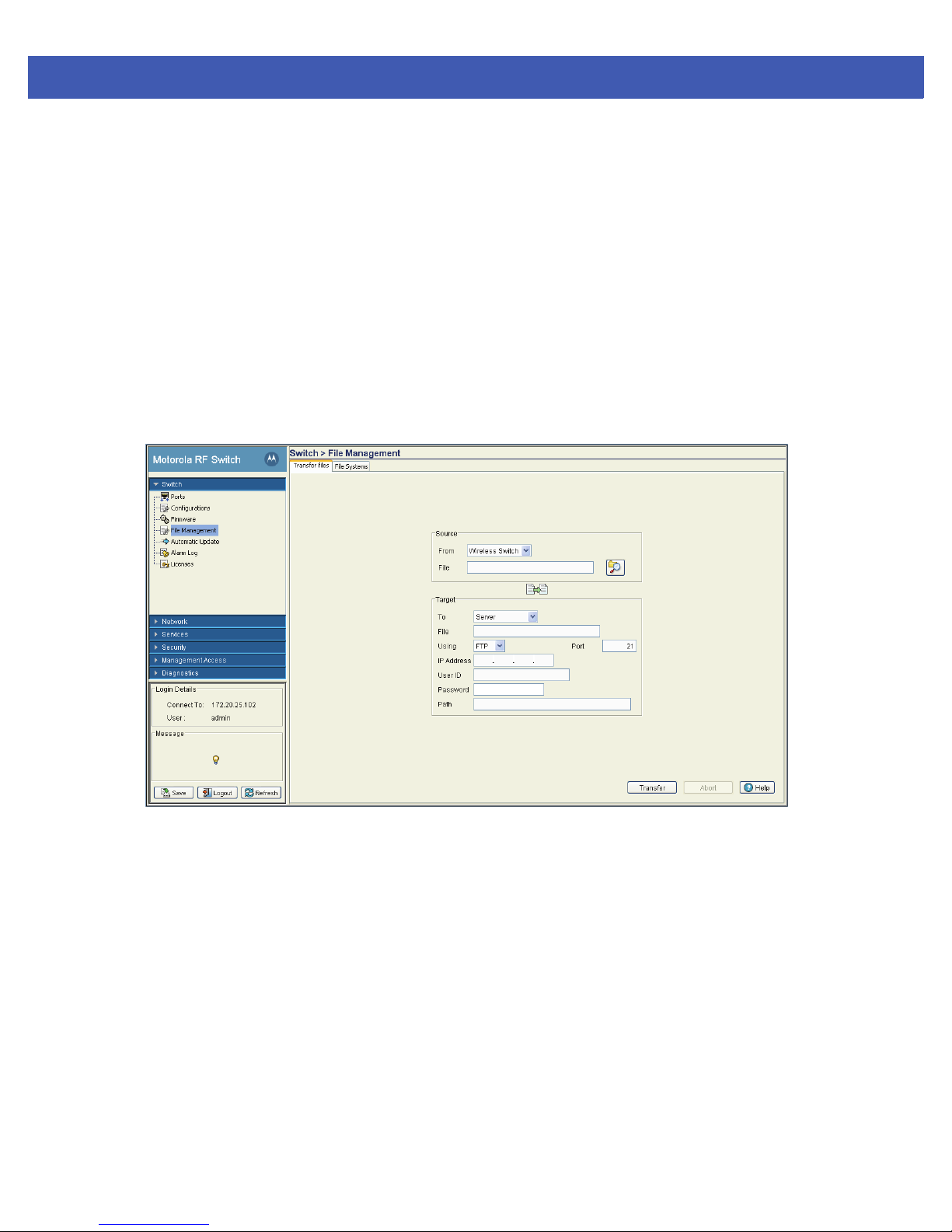
3 - 34 WiNG 4.4 Switch System Reference Guide
3.5 Switch File Management
Use the File Management screen to transfer configuration file to and from the switch and review the files available.
3.5.1 Transferring Files
Use the Transfer Files screen to transfer files to and from the switch.Transferring files is recommended to keep files in a
secure location. The following file transfer options are available:
• Wireless Switch to Wireless Switch
• Wireless Switch to Server
• Server to Wireless Switch
To define the properties of the file transfer configuration:
1. Select Switch > File Management from the main menu tree.
2. Refer to the Status field to specify the details of the source file.
From Use the From drop-down menu to select the source file’s current location. The options include
Wireless Switch and Server. The following transfer options are possible:
• Wireless Switch to Wireless Switch
• Wireless Switch to Server
• Server to Wireless Switch.
The parameters displayed in the Source and Target fields differ based on the above selection.
These different kinds of file transfer techniques are described in the sections that follow.
File Use the Browse button to navigate to a target file for transfer. If the switch is selected from the
From drop-down menu (within the Source field), the file used at startup automatically displays.
Page 93
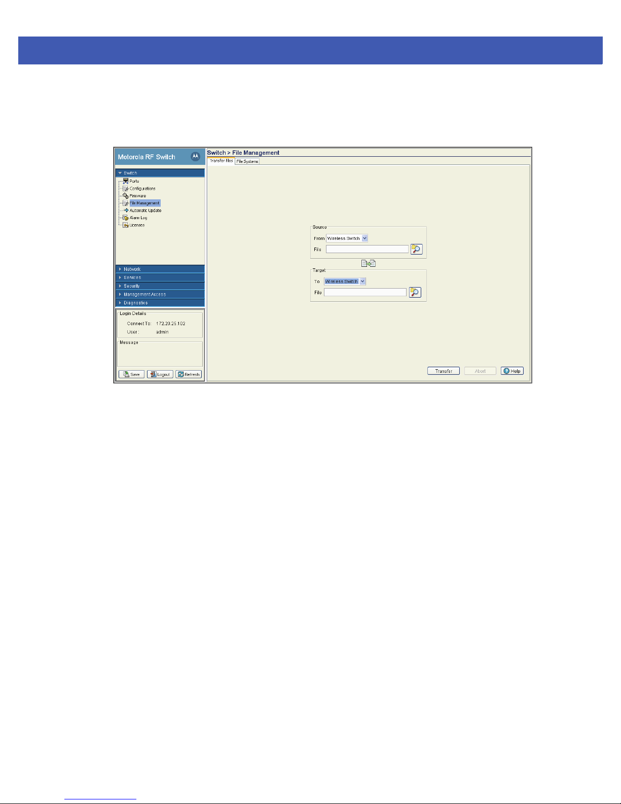
3.5.1.1 Transferring a file from Wireless Switch to Wireless Switch
To transfer a file from one switch to another:
1. Select Wireless Switch from the From drop-down menu
Switch Information 3 - 35
2. Use the Browse button to locate a target file for the file transfer.
3. Use the To drop-down menu (within the Target field) and select Wireless Switch. This defines the location of the
file.
4. Use the Browse button to define a location for the transferred file.
5. Click the Tra ns fe r button to complete the file transfer.
6. The Message section in the main menu area displays the file transfer message.
7. Click Abort at any time during the transfer process to abort the file transfer.
Page 94
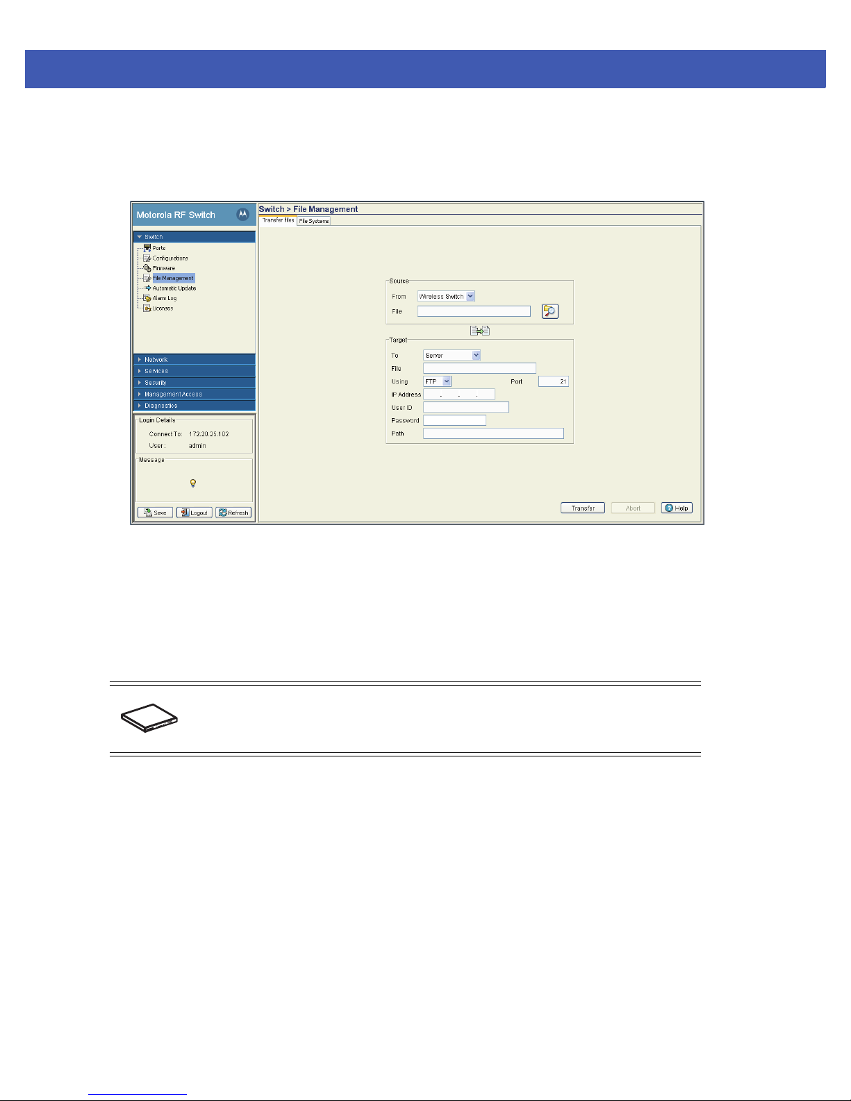
3 - 36 WiNG 4.4 Switch System Reference Guide
3.5.1.2 Transferring a File from a Wireless Switch to a Server
To transfer a file from the Switch to a Server:
1. Refer to the Source field to specify the source file. Use the From drop-down menu and select Wireless Switch.
2. Use the Browse button and select a file for transfer.
3. Use the To drop-down menu (within the Target field) and select Server. This defines the transfer location of the
configuration file. Enter the file location marked to store the transferred file.
4. Use the Using drop down-menu to configure whether the log file transfer is conducted using FTP, TFTP, or SFTP. This
field displays the default port for FTP,TFTP, or SFTP. The value in this field can be configured as required. Enter the IP
Address of the server receiving the source configuration. Ensure the IP address is valid or risk jeopardizing the success
of the file transfer. Enter the User ID credentials required to transfer the configuration file from an FTP server.
Switch Note: On the RFS7000, users can also transfer files using USB or Compact Flash.
On the RFS6000, users can also transfer files using USB. On the RFS4000, users can also
transfer the files using USB, or PCI Express.
5. Enter the Password required to send the configuration file from an FTP server.
6. Specify the appropriate Path name to the target directory on the server. The target options are different depending on
the target selected.
7. Click the Tra ns fe r button to complete the file transfer. The Message section in the main menu area displays the file
transfer message.
8. Click Abort at any time during the transfer process to abort the file transfer.
Page 95
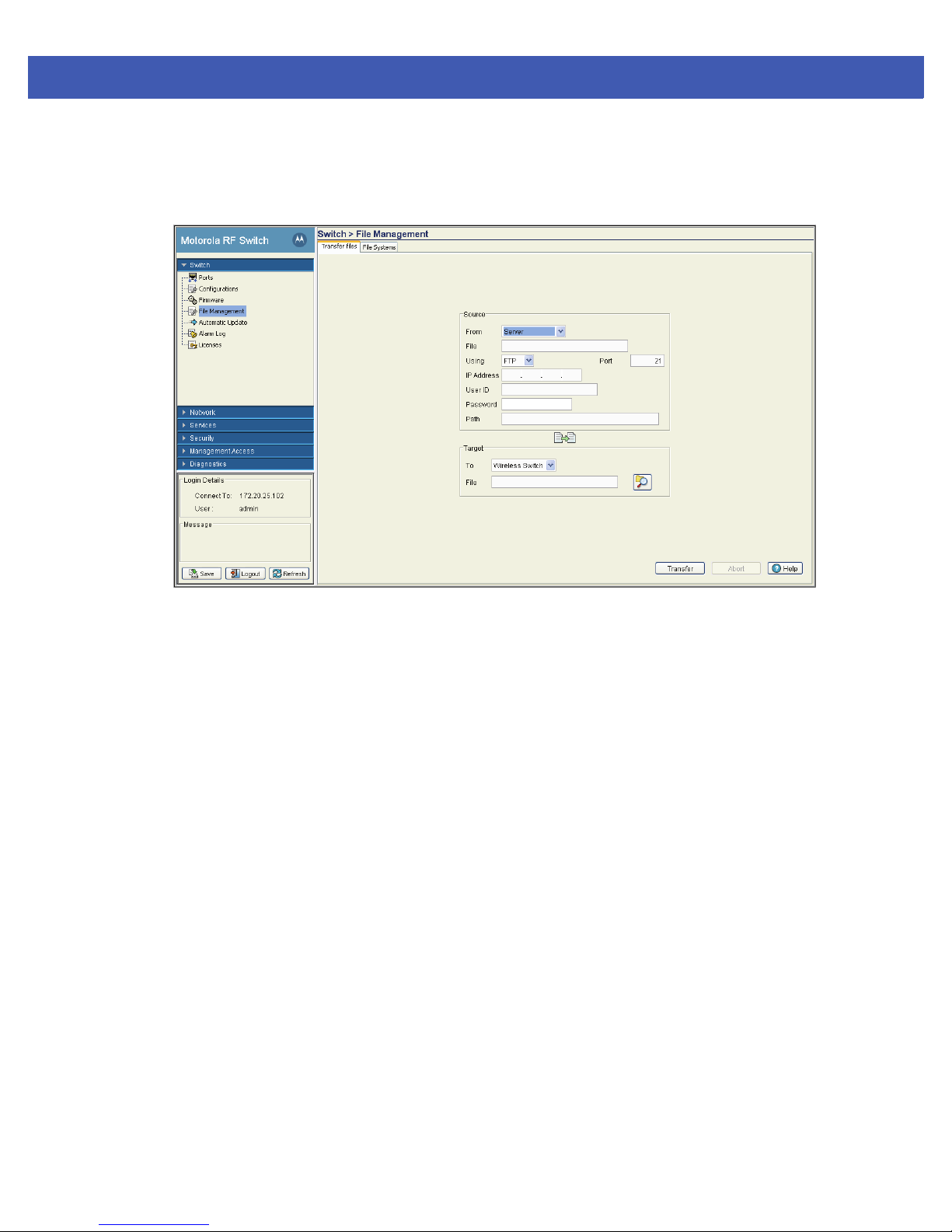
3.5.1.3 Transferring a File from a Server to a Wireless Switch
To transfer a file from a Server to the switch:
1. Refer to the Source field to specify the details of the source file. Use the From drop-down menu and select Server.
Switch Information 3 - 37
2. Provide the name of the File.
3. Use the Using drop-down menu to configure whether the file transfer is conducted using FTP, TFTP, or SFTP.
FTP transfers require a valid user ID and password.
4. Enter an IP Address of the server receiving the configuration file. Ensure that the IP address is valid or risk jeopardizing
the success of the file transfer.
5. Enter the User ID credentials required to transfer the configuration file from an FTP server.
6. Enter the Password required to send the configuration file from an FTP server.
7. Specify the appropriate Path name to the target directory on the server. The Tar ge t options are different depending
on the target selected.
8. Use the To drop-down menu (within the Target field) and select Wireless Switch.
9. Use the Browse button to browse and select the location to store the file marked for transfer.
10.Click the Tran sf er button to complete the file transfer. The Message section displays the status of the file transfer
message.
11.Click the Abort button any time during the transfer process to abort the file transfer.
3.5.2 Viewing Files
Use the File System tab to review the files available to the switch. The switch maintains the following file types:
•flash
•nvram
• system
• Compact Flash
Page 96
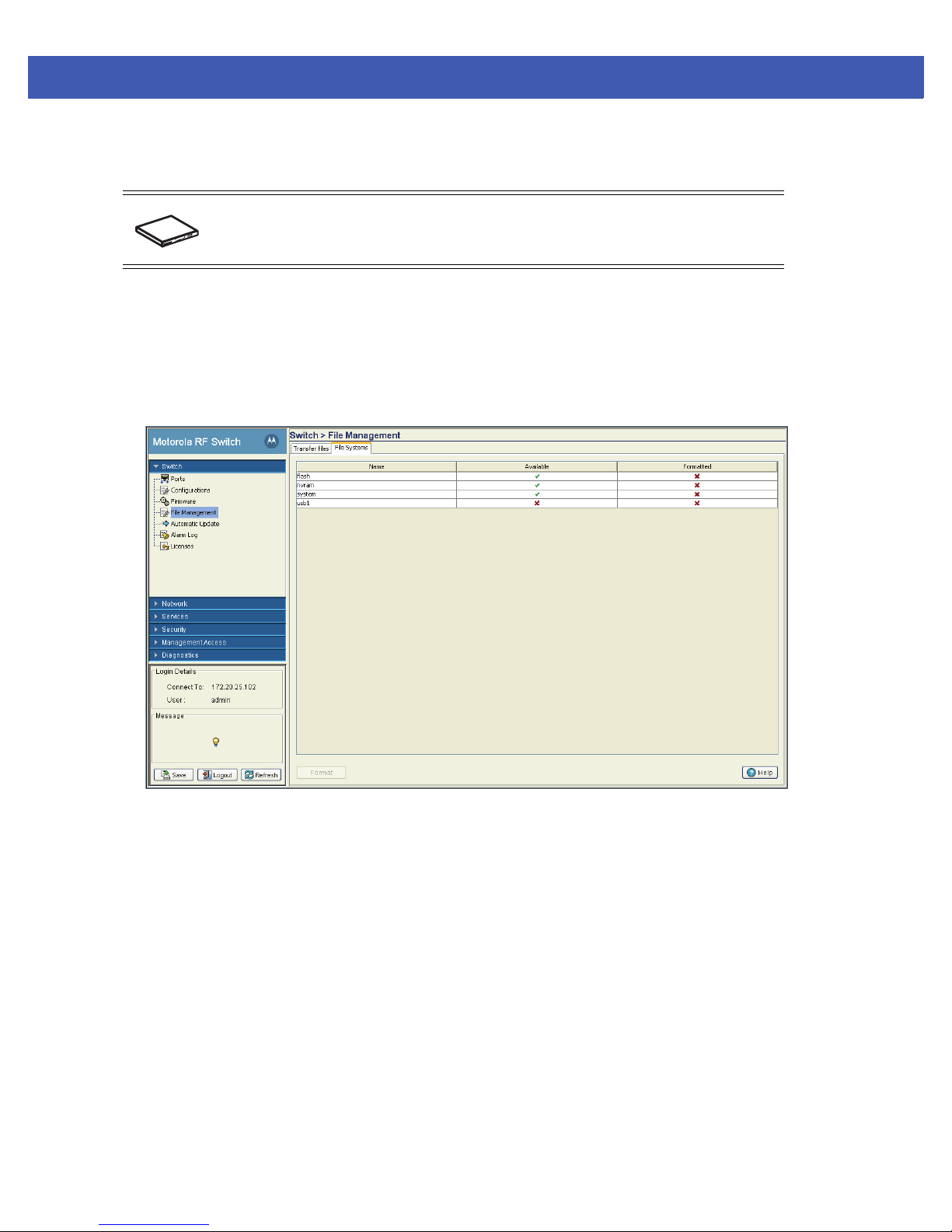
3 - 38 WiNG 4.4 Switch System Reference Guide
•USB 1
•USB 2
Switch Note: USB 1 is available on the RFS6000 and RFS7000 switches. USB2 and Compact Flash are only available on the RFS7000 switch.
Transfer files between the switch and the server from any one of the above mentioned locations. Since compact flash (CF)
and USB are external memory locations, the File System window displays the status of these devices. Transfer files to
compact flash and USB only if they are connected and available.
To view the file systems currently available to the switch:
1. Select Switch > File Management from the main menu tree.
2. Select the File System tab.
3. Refer to the following File Systems information.
Name Displays the memory locations available to the switch.
Available Displays the current status of the memory resource. By default, nvram and system are always
available.
• A green check indicates the device is currently connected to the switch and is available.
• A red X indicates the device is currently not available.
Formatted This displays the format status of the memory devices. This ensures that the external and internal
memory devices store the files securely. A formatted memory device is less prone to crash and loss
of data.
• A green check mark indicates that the device is currently connected to the switch and is
available.
• A red X indicates that the device is currently not available.
Page 97
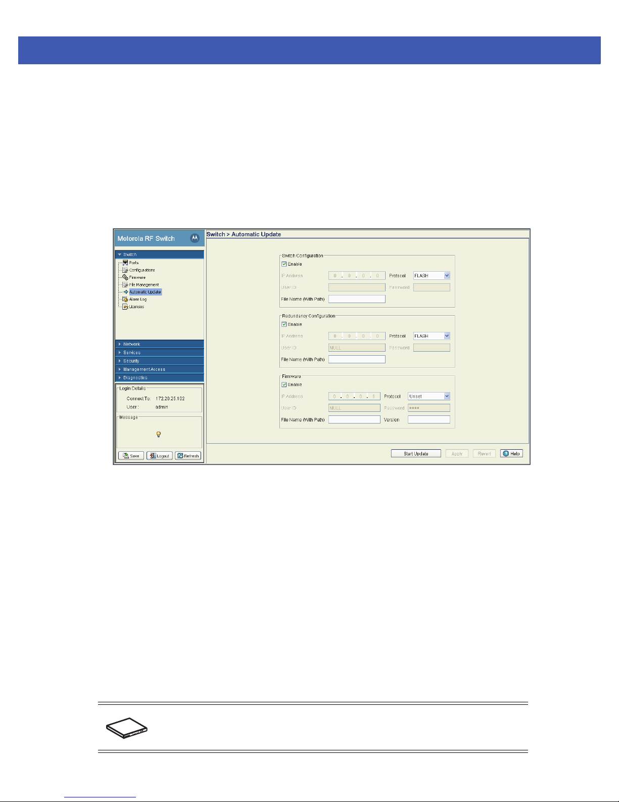
Switch Information 3 - 39
3.6 Configuring Automatic Updates
Use the Automatic Updates screen to enable a facility that will poll a server address (you designate) when the switch is
booted. If updates are found since the last time the switch was booted, the updated version is uploaded to the switch the
next time the switch is booted. Enable this option for either the firmware, configuration file, or cluster configuration file.
Motorola Solutions recommends leaving this setting disabled if a review of a new file is required before it is automatically
uploaded by the switch.
To enable and configure the automatic update feature for switch firmware, configuration files, and cluster configurations:
1. Select Switch > Automatic Updates from the main menu tree.
2. Refer to the Switch Configuration field to enable and define the configuration for automatic configuration file
updates. If enabled, the located (updated) configuration file will be used with the switch the next time the switch boots.
Enable Select the Enable checkbox to allow an automatic configuration file update when a newer
(updated) file is detected (upon the boot of the switch) at the specified IP address.
IP Address Define the IP address of the server where the configuration files reside. If a new version is
detected when the switch is booted, it is uploaded to the switch and used upon the next boot of
the switch.
User ID Enter the User ID required to access the FTP or TFTP server.
File Name (With
Path)
Protocol Use the Protocol drop-down menu to specify the FTP, TFTP, HTTP, SFTP, or resident switch
Password Enter the password required to access the server.
Switch Note: In addition to the Protocols listed on the RFS7000, users can also autoupdate using USB or Compact Flash. On the RFS6000, users can also auto-update using
USB.
Provide the complete and accurate path to the location of the configuration files on the server. This
path must be accurate to ensure that the most recent file is retrieved.
FLASH medium used for the file update from the server. FLASH is the default setting.
Page 98

3 - 40 WiNG 4.4 Switch System Reference Guide
3. Refer to the Redundancy Configuration field to enable and define the configuration for automatic cluster file
updates.
Enable Select the Enable checkbox to allow an automatic cluster file update when a new (updated) file
is detected (upon the boot of the switch) at the specified IP address.
IP Address Define the IP address of the server where the cluster files reside. If a new version is detected
when the switch is booted, it will be uploaded to the switch and used upon the next boot of the
switch.
User ID Enter the User ID required to access the FTP or TFTP server.
File Name (With
Path)
Provide the complete and accurate path to the location of the cluster files on the server. This path
must be accurate to ensure that the most recent file is retrieved.
Protocol Use the Protocol drop-down menu to specify the FTP, TFTP, HTTP, SFTP, or resident switch
FLASH medium used for the file update from the server. FLASH is the default setting.
Password Enter the password required to access the server.
4. Refer to the Firmware field to enable and define the configuration for automatic firmware updates. If enabled, the
located (updated) switch firmware is used with the switch the next time the switch boots.
Enable Select the Enable checkbox to allow an automatic firmware update when a new (updated) version
is detected (upon the boot of the switch) at the specified IP address.
IP Address Define the IP address of the server where the firmware files reside. If a new version is detected
when the switch is booted, it will be uploaded to the switch and used upon the next boot of the
switch.
User ID Enter the User ID required to access the FTP or TFTP server.
File Name (With
Path)
Provide the complete and accurate path to the location of the firmware files on the server. This
path must be accurate to ensure that the file is retrieved.
Protocol Use the Protocol drop-down menu to specify the FTP, TFTP, HTTP, SFTP, or resident switch
FLASH medium used for the file update from the server. FLASH is the default setting.
Password Enter the password required to access the server.
Version Provide the target firmware version to ensure that the switch is upgrading to the intended
baseline.
5. Select the Start Update button to begin the file updates for the enabled switch configuration, cluster configuration,
or firmware facilities.
6. Click the Apply button to save the changes to the configuration.
7. Click the Revert button to revert back to the last saved configuration.
Page 99
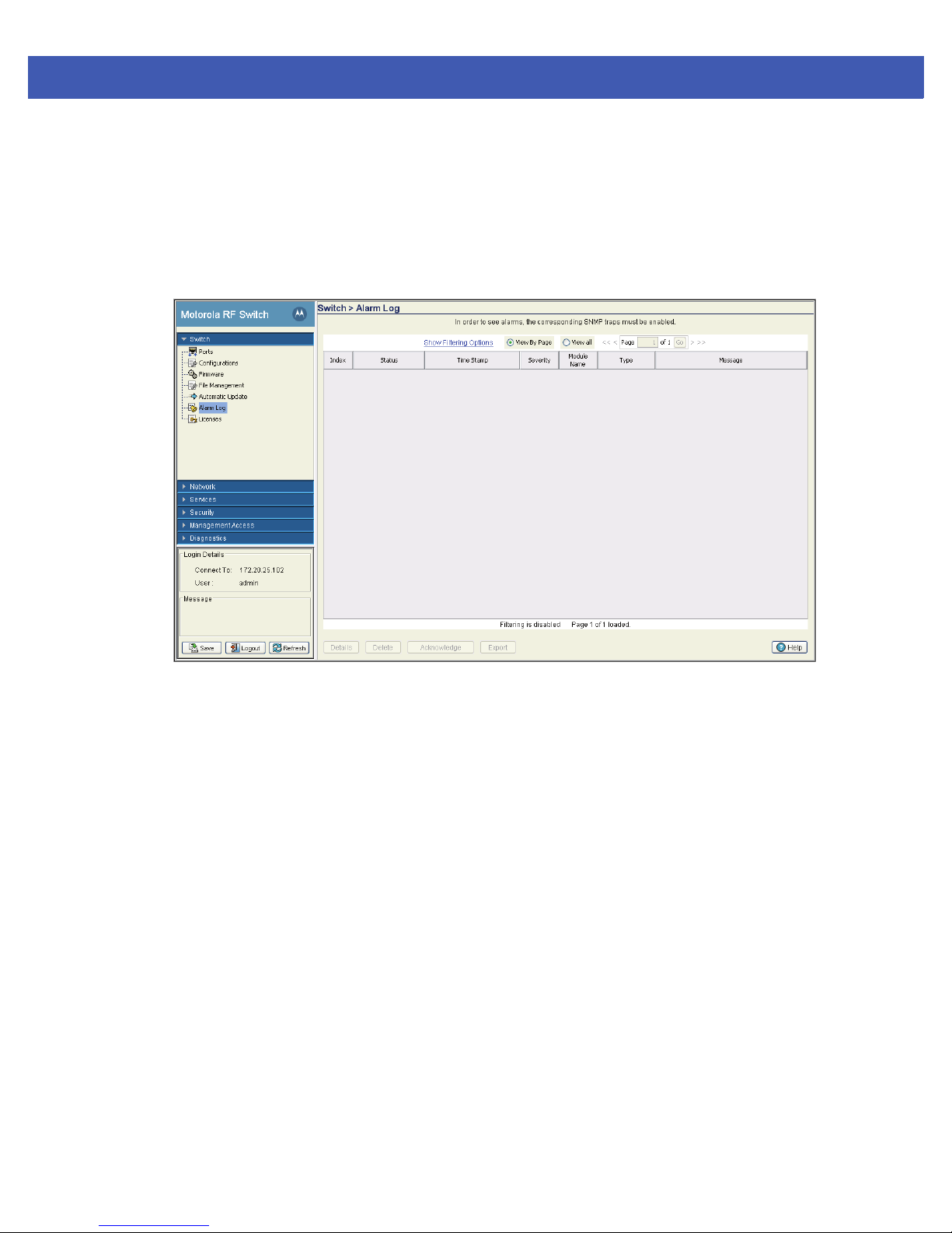
3.7 Viewing the Switch Alarm Log
Use the Alarm Log screen as an initial snapshot for alarm log information. Expand alarms (as needed) for greater
detail, delete alarms, acknowledge alarms, or export alarm data to a user-specified location for archive and network
performance analysis.
To view switch alarm log information:
1. Select Switch > Alarm Log from the main menu tree.
Switch Information 3 - 41
2. Use the Alarm Log screen’s filtering options to view alarm log data by page or by its entire content.
3. Select either of the two available options to view alarm log information:
View By Page Select the View By Page radio button to view alarm log information on a per page basis. Use the
View By Page option to page through alarm logs. If there are a large number of alarms, the user
can navigate to the page that has been completely loaded. All operations can be performed on the
currently loaded data. Enter a page number next to “Page” and click the Go button to move to the
specific page.
View All Select the View All radio button to display the complete alarm log within the table. If there are
a large number of alarms, the View All option will take several minutes to load.
4. Refer to the table within the Alarm Log screen for the following information:
Index Displays the unique numerical identifier for trap events (alarms) generated in the system. Use the
index to help differentiate an alarm from others with similar attributes.
Status Displays the current state of the requests made from the applet. Requests are any “SET/GET”
operation from the applet. The Status displays error messages if something goes wrong in the
transaction between the applet and the switch.
Time Stamp Displays the date, year, and time the alarm was raised (as well as the time zone of the system).
The time stamp only states the time the alarm was generated, not the time it was acknowledged.
Page 100
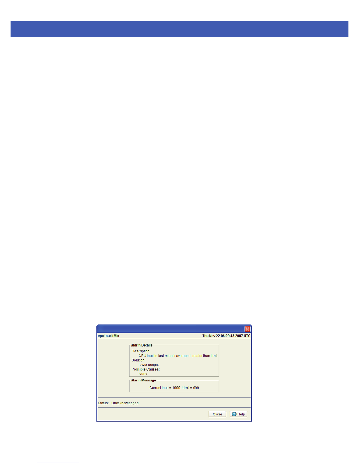
3 - 42 WiNG 4.4 Switch System Reference Guide
Severity Displays the severity level of the event. Use this (non numerical and verbal) description to assess
the criticality of the alarms. Severity levels include:
• Critical
• Major
• Warning
• Informational
•Normal
Module Name Displays the module name that triggered this alarm. Use this information to assess if this alarm
is a recurring problem or if it is an isolated incident.
Type Displays the alarm type.
Message Displays a detailed event message corresponding to the alarm event. It contains an event-specific
message for information about the alarm. Use this value along with the Details description for
optimal problem event identification.
5. Select an alarm and click the Details button to display an alarm description along with a system proposed solution
and possible causes. For more information, see
Viewing Alarm Log Details on page 3-42.
6. Select the alarm(s) from those listed and click the Delete button to remove them from the list of alarms.
This is not recommended in instances where the problem is unacknowledged and the criticality has not yet been
assessed.
7. Select the unacknowledged alarm(s) from those listed and click the Acknowledge button to acknowledge them.
8. Click the Export button to export the content of the table to a Comma Separated Values file (CSV).
3.7.1 Viewing Alarm Log Details
Use the Details option when additional information is required for a specific alarm to make an informed decision on
whether to delete, acknowledge, or export the alarm.
To review switch alarm details:
1. Select Switch > Alarm Log from the main menu tree.
2. Select an alarm and click the Details button.
 Loading...