

Page 1
VT100
QUICKSTART GUIDE
Page 2

TABLE OF CONTENTS
INTRODUCTION 3
HOW TO CHARGE YOUR VT100 3
HOW TO USE YOUR VT100 6
HOW TO POWER UP YOUR VT100 6
IF YOUR VT100 IS CONFIGURED TO LIVESTREAM 7
IF YOUR VT100 IS NOT CONFIGURED TO LIVESTREAM 7
HOW TO STOP RECORDING 8
WEARING YOUR VT100 9
VT100 ROTATABLE LONG ALLIGATOR CLIP 10
VT100 KLICK FAST STUD 11
VT100 SPORTS CAMERA PILLAR 12
VT100 EPAULETTE (SHOULDER) CLIP 13
LANYARDS 15
REGULATORY INFORMATION 16
QUICKSTART GUIDE | VT100 2
Page 3
INTRODUCTION
Thank you for choosing the VT100 Body-worn camera. This simple guide will lead you through the set up and
use of your VT100.
The VT100 is designed to function on standby for up to six months. Therefore, it is necessary to fully charge the
device before first use.
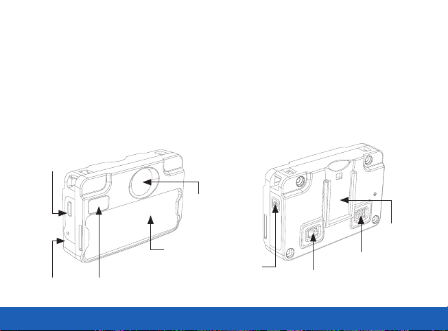
FRONT BACK
Micro
USB Port
Lens
Attachment
Slot for
Custom ID Card
Microphone
QUICKSTART GUIDE | VT100 3
LED
LED
Press to Record
Button & LED
Press to Record
Button & LED
Point for Clip
Page 4
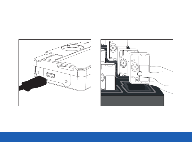
HOW TO CHARGE YOUR VT100
To charge, you will need either a USB charging cable (AC-USB-MICROB-100) or the VT100 variant of the
14-Port Dock (VT-100-DOCK14).
USB Charging Cable
(AC-USB-MICROB-100)
QUICKSTART GUIDE | VT100 4
VT100 14-Port Dock
(VT-100-DOCK14)
Page 5
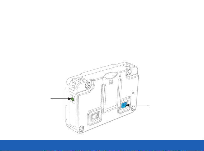
While connected to power, the LED on the right side of the device will flash green while charging, and will go a
solid green when fully charged.
If the VT100 is configured to connect to Wi-Fi® while docking, the back-right LED will flash blue when searching
for a Wi-Fi connection, and will become a solid blue when a Wi-Fi connection is found.
If your VT100 has not already been configured by your system administrator, please see the VideoManager
Admin Guide for details on how to configure your VT100.
CHARGING
(Flashing Green)
SEARCHING FOR WI-FI
(Flashing Blue)
CONNECTED TO WI-FI
(Solid Blue)
QUICKSTART GUIDE | VT100 5
Page 6

HOW TO USE YOUR VT100
HOW TO POWER UP YOUR VT100
The VT100 starts recording (and live streaming, if it has been configured to do so), as soon as it is powered up.
To power up your device, press either of the two buttons on the back of the device. The device will vibrate
briefly, and recording will start.
POWERING UP YOUR VT100
Press and hold either
of the power buttons
QUICKSTART GUIDE | VT100 6
Page 7

IF YOUR VT100 IS CONFIGURED TO LIVESTREAM
The recording LED on the back-left of the device should shine solid red, as well as the LED on the front of the
device. This indicates that the device is recording. The LED on the back-right of the device should be flashing
blue - about once a second - indicating that it is looking for Wi-Fi to connect to.
A solid blue light on the back-right LED indicates that the VT100 has connected to the Wi-Fi.
IF YOUR VT100 IS NOT CONFIGURED TO LIVESTREAM
The recording LED on the back-left of the device should now be a solid red, as well as the LED on the front of
the device. This indicates that the device is recording.
RECORDING
(Solid Red)
SEARCHING FOR WI-FI
(Flashing Blue)
CONNECTED TO WI-FI
RECORDING
(Solid Red)
QUICKSTART GUIDE | VT100 7
(Solid Blue)
Page 8

HOW TO STOP RECORDING
To stop recording, press and hold either of the buttons on the back of your device for one second.
The LED on the front of the device will switch o. If your VT100 is configured to livestream, the back-right
LED will remain a solid blue, indicating that the device is still connected to the Wi-Fi, but no footage is being
recorded. After 10 more seconds, the camera will automatically switch o.
Once recording has stopped, the VT100 will always automatically power down after ten seconds of inactivity in
order to preserve battery life.
CONNECTED TO WI-FI
(Solid Blue)
This light will go out
after 10 seconds
STOPPED
RECORDING
(No LED)
POWERING DOWN
YOUR VT100
STOPPED
RECORDING
(No LED)
QUICKSTART GUIDE | VT100 8
Press and hold either
of the power buttons
Page 9

WEARING YOUR VT100
The VT100 can be attached to most uniforms and items of clothing using one of the robust clips which can be
purchased from Motorola Solutions (see following pages for options available).
These clips are rotatable - however, the camera should always remain upright when capturing footage.
QUICKSTART GUIDE | VT100 9
Page 10

VT100 ROTATABLE LONG ALLIGATOR CLIP
To attach a Rotatable Long Alligator clip (VT-100-FIX-ALIG) to your VT100, slide the attachment into the mounting
rail on the back of your device until a firm click is heard and the attachment point is held firmly in place.
To detach the clip clip from your VT100, pull the lip of the attachment plate away from the body of your VT100
and firmly pull the attachment out of the rails.
Slide rotatable
attachment down
QUICKSTART GUIDE | VT100 10
Page 11

VT100 KLICK FAST STUD
To attach a Klick Fast stud to your VT100, you will need:
• A VT100
• A VT100 Klick Fast Stud (VT-100-FIX-KF-ALT)
• A Klick Fast dock (usually on a uniform),
Firstly, pinch the two metal clips on the back of the stud together, and slide the attachment into the mounting
rail on the back of your device until a firm click is heard. Release the metal clips.
Slide the VT100 into the Klick Fast dock upside-down, so the device’s serial number is pointing towards the
ceiling. Once the stud is firmly attached to the dock, rotate the VT100 by twisting it until it is the right way up.
To detach a Klick Fast stud from the Klick Fast dock, rotate the device by 180 degrees, so the VT100 is upside
down again. The stud should slide out of the dock easily. It is now possible to detach the stud from the VT100.
To do so, pinch the two metal clips on the back of the stud together, and slide the stud upwards out of the
attachment rail.
QUICKSTART GUIDE | VT100 11
Page 12

VT100 SPORTS CAMERA PILLAR
To attach a sports camera pillar to your VT100, you will need:
• A VT100
• A VT100 Sports Camera Pillar (VT-100-FIX-SPORT)
• A sports camera accessory to attach the camera to
• A securing pin (usually supplied with the sports camera accessory)
• A securing nut (usually permanently attached to the sports camera accessory)
Firstly, pinch the two metal clips on the back of the stud together, and slide the attachment into the mounting
rail on the back of your device until a firm click is heard. Release the metal clips.
Slide the sports camera pillar between the teeth of the accessory, so the holes align. Push the securing pin
through the two components, and into the securing nut
To detach a VT100 from the sports camera stud, pinch the two metal clips on the back of the stud together, and
slide the stud (with the sports camera pillar) upwards out of the attachment rail.
QUICKSTART GUIDE | VT100 12
Page 13

VT100 EPAULETTE (SHOULDER) CLIP
To attach your VT100 to an epaulette, you will need:
• A VT100
• An Epaulette (Shoulder) Clip (VT-100-FIX-EP)
Firstly, attach your VT100 to the mount by pulling the metal
clip on the back of the stud towards the mount, and sliding the
attachment into the mounting rail on the back of your VT100
until a firm click is heard.
Hold your VT100 vertically, underneath the epaulette. Keeping
the clip open, push the mount through the epaulette. It may be
necessary to position the mount at a slight angle if it doesn’t
fit initially.
Release the clip when it is fully through the epaulette,
and fit the hook over your epaulette’s button (if present) to
secure.
QUICKSTART GUIDE | VT100 13
Page 14

You can change the vertical angle of your VT100 by adjusting the stud on the back of your device to point up or
down.
To detach a VT100 from the epaulette clip, pull the metal clip on the back of the stud towards the mount, and
slide the stud (with the epaulette clip) upwards out of the attachment rail.
To detach an epaulette mount from your uniform, slide the mount upwards slightly so the hook detaches from
your epaulette’s button. Open the clip and rotate the mount by 90 degrees while pulling down on it. This should
help the mount to slide out easily.
This can also be used to attach a VT100 to a radio loop or rucksack loop, following the same instructions.
QUICKSTART GUIDE | VT100 14
Page 15

LANYARDS
The Motorola Solutions lanyard (AC-LANYARD-05) is a long piece of sturdy polyester ribbon, with a split ring at
each end and a phone strap attached to each split ring. It has five break points for added safety - allowing for
quick release if pulled on.
To attach a VT100:
• Unclip both phone straps from the lanyard
• Push each of the phone straps through the two small
holes (tether points) in both corners of the VT100
• Loop through to secure
• Re-attach to the lanyard clips
• Put the lanyard on and adjust length to suit using the
break points
Your VT100 is now securely attached to your uniform
QUICKSTART GUIDE | VT100 15
Page 16

REGULATORY INFORMATION
FCC
This device complies with part 15 of the FCC Rules. Operation is subject to the following two conditions: (1) This device may not cause harmful interference,
and (2) this device must accept any interference received, including interference that may cause undesired operation.
NOTE: This equipment has been tested and found to comply with the limits for a Class B digital device, pursuant to Part 15 of the FCC Rules. These
limits are designed to provide reasonable protection against harmful interference in a residential installation. This equipment generates uses and
can radiate radio frequency energy and, if not installed and used in accordance with the instructions, may cause harmful interference to radio
communications. However, there is no guarantee that interference will not occur in a particular installation. If this equipment does cause harmful
interference to radio or television reception, which can be determined by turning the equipment o and on, the user is encouraged to try to correct
the interference by one of the following measures:
• Reorient or relocate the receiving antenna.
• Increase the separation between the equipment and receiver.
• Connect the equipment into an outlet on a circuit dierent from that to which the receiver is connected.
• Consult the dealer or an experienced radio/TV technician for help.
WARNING: Any changes or modifications not expressly approved by the party responsible for compliance could void the user’s authority to operate
this equipment.
The device must not be co-located or operating in conjunction with any other antenna or transmitter.
QUICKSTART GUIDE | VT100 16
Page 17

FCC RF EXPOSURE INFORMATION (SAR)
This device is designed and manufactured not to exceed the emission limits for exposure to radio frequency (RF) energy set by the Federal
Communications Commission of the U.S. Government.
The exposure standard for wireless devices employs a unit of measurement known as the Specific Absorption Rate, or SAR. The SAR limit set by the
FCC is 1.6 W/kg. Tests for SAR are conducted using standard operating positions accepted by the FCC with the device transmitting at its highest
certified power level in all tested frequency bands. Although the SAR is determined at the highest certified power level, the actual SAR level of the
device while operating can be well below the maximum value. This is because the device is designed to operate at multiple power levels so as to use
only the poser required to reach the network.
In general, the closer you are to a wireless base station antenna, the lower the power output. While there may be dierences between the SAR levels of
various devices and at various positions, they all meet the government requirement.
INDUSTRY CANADA STATEMENT
This device complies with RSS247 of Industry Canada. Cet appareil se conforme à RSS247 de Canada d’Industrie. This device complies with Industry
Canada license-exempt RSS standard(s). Operation is subject to the following two conditions: (1) this device may not cause interference, and (2) this
device must accept any interference, including interference that may cause undesired operation of the device. appareils radio exempts de licence.
Son fonctionnement est sujet aux deux conditions suivantes: (1) le dispositif ne doit pas produire de brouillage prejudiciable, et (2) ce dispositif doit
accepter tout brouillage recu, y compris un brouillage susceptible de provoquer un fonctionnement indesirable.
The device must not be co-located or operating in conjunction with any other antenna or transmitter.
EXPOSURE OF HUMANS TO RF FIELDS (RSS-102)
The radiated energy from the antennas connected to the wireless adapters conforms to the IC limit of the RF exposure requirement regarding IC
RSS102, Issue 5 clause 4. SAR tests are conducted using recommended operating positions accepted by the RSS with the device transmitting at its
highest certified power level in all tested frequency band without distance attaching away from the body.
CONFORMITÉ DES APPAREILS DE RADIOCOMMUNICATION AUX
LIMITES D’EXPOSITION HUMAINE AUX RADIOFRÉQUENCES (CNR-102)
L’énergie émise par les antennes reliées aux cartes sans fil respecte la limite d’exposition aux radiofréquences telle que définie par Industrie Canada
dans la clause 4.1 du document CNR-102, version 5. Tests DAS sont eectués en utilisant les positions recommandées par la CNR avec le téléphone
émet à la puissance certifiée maximale dans toutes les bandes de fréquences testées sans distance attacher loin du corps.
QUICKSTART GUIDE | VT100 17
Page 18

For more information, please visit: www.motorolasolutions.com
Motorola Solutions Ltd. Nova South, 160 Victoria Street, London, SW1E 5LB, United Kingdom
Availability is subject to individual country law and regulations. All specifications shown are typical unless
otherwise stated and are subject to change without notice. MOTOROLA, MOTO, MOTOROLA SOLUTIONS
and the Stylized M Logo are trademarks or registered trademarks of Motorola Trademark Holdings, LLC
and are used under license. All other trademarks are the property of their respective owners.
© 2020 Motorola Solutions, Inc. All rights reserved. (09/20) (ED-006-012-13)
 Loading...