

Page 1
VB400
QUICKSTART GUIDE
Page 2

TABLE OF CONTENTS
INTRODUCTION 3
HOW TO CHARGE YOUR VB400 4
CHARGING WITH A 1-PORT DOCK 5
CHARGING WITH A 14-PORT DOCK 6
BATTERY STATUS LED 7
CONFIGURING YOUR VB400 8
IDENTIFYING AN RFID ASSIGNED VB400 9
USING YOUR VB400 10
TO START / STOP RECORDING 10
WEARING YOUR VB400 12
ACCESSORIES 12
REGULATORY INFORMATION 13
QUICKSTART GUIDE | VB400 2
Page 3
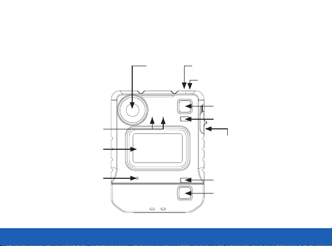
INTRODUCTION
Thank you for choosing the VB400 Body-worn camera. This simple guide will lead you through the set up and
use of your VB400.
Dual
Microphone
Front
Function Button
Lens
Function
Button A
LED
Function
Button B
LED
Slider
Buzzer Speaker
QUICKSTART GUIDE | VB400 3
LED
Function
Button C
Page 4
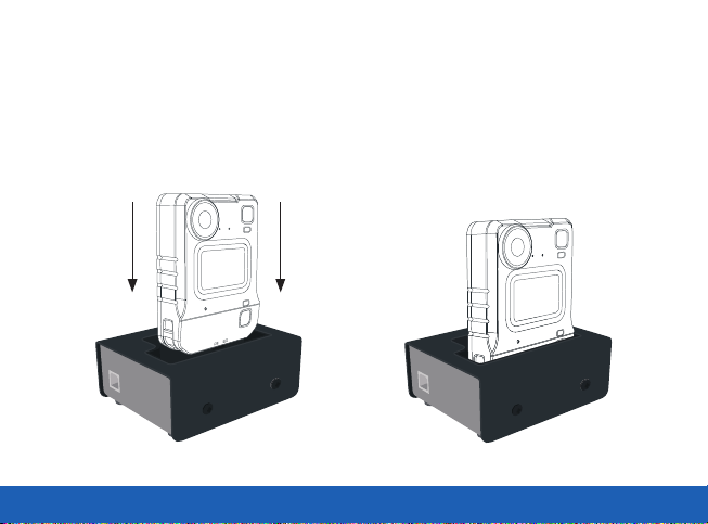
HOW TO CHARGE YOUR VB400
Upon receiving your VB400, it is recommended that you fully charge the device before usage.
When charging using a 1-Port Dock or 14-Port Dock, insert the camera into the slots as shown below,
ensuring the camera clicks securely in place. Check that the top LED blinks green to indicate charging.
Slide down to
click into place
QUICKSTART GUIDE | VB400 4
Page 5
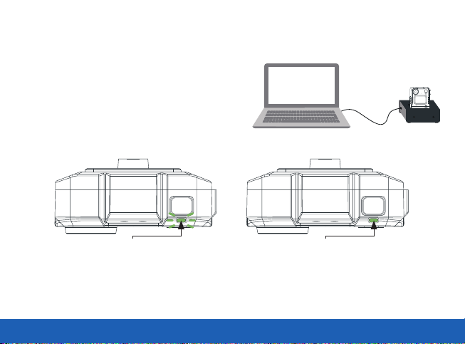
CHARGING WITH A 1-PORT DOCK
(VB-400-DOCK-SOLO)
• Connected to your laptop or DockController.
If you are charging your VB400 camera via a 1-Port Dock
(VB-400-DOCK-SOLO) your camera will bleep to indicate
charging has commenced, and the LED, as indicated, will
flash green to show charging.
Charging: Flashing green LED Fully Charged: Solid green LED
Once fully charged, the same LED will turn solid green. If the LED is not lit, the device is not charging.
Your VB400 will be fully charged within 8 hours from a flat battery.
QUICKSTART GUIDE | VB400 5
Page 6

CHARGING WITH A 14-PORT DOCK
(VB-400-DOCK-14)
• Connected to a power supply
and DockController
If you are charging your VB400 camera via a 14-Port
Dock (VB-400-DOCK-14) the top LED will flash green
to show charging, and the camera will bleep when
successfully connected to VideoManager.
Charging: Flashing green LED Fully Charged: Solid green LED
Once fully charged, the same LED will turn solid green. If the LED is not lit, the device is not charging. Your
VB400 will be fully charged within 8 hours from a flat battery.
QUICKSTART GUIDE | VB400 6
Page 7

BATTERY STATUS LED
To quickly understand the current battery status of your VB400, press the bottom button on the front face of the
camera and refer to the bottom LED.
Colour Key:
Green LED: OK
Orange/Yellow LED: Low
Red LED: Critical
Battery Status Button
(Configurable)
QUICKSTART GUIDE | VB400 7
Page 8

CONFIGURING YOUR VB400
Prior to using your VB400, your device must be
configured and assigned to you using VideoManager.
For detailed information on how to configure your
device, please refer to the VideoManager User Guide.
Each VB400 requires a valid VideoManager Licence, or
access to the VideoManager Cloud Service, in order for
you to assign devices and access footage. For further
details, see the VideoManager User Guide.
To ascertain whether your VB400 has been configured,
please view the top LED on your device. This LED will
turn solid green once configured and assigned. Your
VB400 is charged, assigned and ready to use when the
LEDs shown are both solid green.
Please Note: If you try to use your VB400 before it has been assigned, the bottom LED on the front face of the
camera will start to flash red and you will hear an alarm tone. You will not be able to use your camera until it
has been assigned.
QUICKSTART GUIDE | VB400 8
Configured, charged &
assigned Solid green light
Page 9

IDENTIFYING AN RFID ASSIGNED VB400
Once your device is configured, your system administrator may wish camera users to utilise an RFID system
for camera assignment. For further information on assigning VB400s using an RFID reader, please refer to the
VideoManager User Guide.
Having presented your RFID card, your docked, assigned VB400 will identify itself with a solid red LED as
shown.
RFID-Card
(RF-CARD-10)
RFID Reader
(RF-220)
QUICKSTART GUIDE | VB400 9
RFID
Assigned Camera
Page 10

USING YOUR VB400
The VB400 series of cameras are intuitive and simple to use.
TO START / STOP RECORDING (CONFIGURABLE)
Users can activate recording by pressing on the single front button located in the centre of the camera as
shown. Recording is stopped by pressing and holding the front button.
Record activation and deactivation buttons are
configurable by Administrators.
Start Recording initiated will be indicated by a short
bleep, the two upper LEDs showing red.
Press centre button to
start/stop recording
Solid red LED
QUICKSTART GUIDE | VB400 10
Page 11

Stop Recording initiated is indicated by the two upper LEDs turning from red to o, accompanied by a longer,
high pitched bleep.
Please Note: All buttons are configurable. Please consult with your administrator if you have any issues.
Power Down Button
(Configurable)
No LED
QUICKSTART GUIDE | VB400 11
Page 12

WEARING YOUR VB400
The VB400 body-worn camera should always remain upright when capturing footage.
ACCESSORIES
Designed for optimum performance and comfort in a wide range of situations, the VB400 comes with a variety
of fixing types to suit every uniform and body shape. For more information on our range of body-worn cameras,
please visit: www.motorolasolutions.com/bwc
QUICKSTART GUIDE | VB400 12
Page 13

REGULATORY INFORMATION
FCC
Responsible party
Name: Motorola Solutions, Inc.
Address: 2000 Progress Pkway, Schaumburg, Il. 60196
Phone Number: 1-800-927-2744
Hereby declares that the product:
Model Name: VB400
Conforms to the following regulations: FCC Part 15, subpart B, section 15.107(a), 15.107(d), and section 15.109(a)
This device complies with part 15 of the FCC Rules. Operation is subject to the following two conditions: (1) This device may not cause harmful interference,
and (2) this device must accept any interference received, including interference that may cause undesired operation.
NOTE: This equipment has been tested and found to comply with the limits for a Class B digital device, pursuant to Part 15 of the FCC Rules. These limits
are designed to provide reasonable protection against harmful interference in a residential installation. This equipment generates uses and can radiate radio
frequency energy and, if not installed and used in accordance with the instructions, may cause harmful interference to radio communications. However, there
is no guarantee that interference will not occur in a particular installation. If this equipment does cause harmful interference to radio or television reception,
which can be determined by turning the equipment o and on, the user is encouraged to try to correct the interference by one of the following measures:
• Reorient or relocate the receiving antenna.
• Increase the separation between the equipment and receiver.
• Connect the equipment into an outlet on a circuit dierent from that to which the receiver is connected.
• Consult the dealer or an experienced radio/TV technician for help.
WARNING: Any changes or modifications not expressly approved by the party responsible for compliance could void the user’s authority to operate this
equipment.
The device must not be co-located or operating in conjunction with any other antenna or transmitter.
QUICKSTART GUIDE | VB400 13
Page 14

CAUTION:
(i) the device for operation in the band 5150-5250 MHz is only for indoor use to reduce the potential for harmful interference to co-channel mobile satellite
systems;
(ii) the maximum antenna gain permitted for devices in the bands 5250-5350 MHz and 5470-5725 MHz shall be such that the equipment complies with the
e.i.r.p. limit;
(iii) the maximum antenna gain permitted for devices in the band 5275-5850 MHz shall be such that the equipment still complies with the e.i.r.p. limits
specified for point-to-point and non-point-to-point operation as appropriate; and
(iv) the worst-case tilt angle(s) necessary to remain compliant with the e.i.r.p. elevation mask requirement set forth in Section 6.2.2(3) shall be clearly
indicated.
(v) Users should also be advised that high-power radars are allocated as primary users (i.e. priority users) of the bands 5250-5350 MHz and 5650-5850 MHz
and that these radars could cause interference and/or damage to LE-LAN devices.
EXPOSURE OF HUMANS TO RF FIELDS (RSS-102)
The radiated energy from the antennas connected to the wireless adapters conforms to the IC limit of the RF exposure requirement regarding IC RSS102,
Issue 5 clause 4. SAR tests are conducted using recommended operating positions accepted by the RSS with the device transmitting at its highest certified
power level in all tested frequency band without distance attaching away from the body.
CONFORMITÉ DES APPAREILS DE RADIOCOMMUNICATION AUX LIMITES D’EXPOSITION HUMAINE
AUX RADIOFRÉQUENCES (CNR-102)
L’énergie émise par les antennes reliées aux cartes sans fil respecte la limite d’exposition aux radiofréquences telle que définie par Industrie Canada dans
la clause 4.1 du document CNR-102, version 5. Tests DAS sont eectués en utilisant les positions recommandées par la CNR avec le téléphone émet à la
puissance certifiée maximale dans toutes les bandes de fréquences testées sans distance attacher loin du corps.
QUICKSTART GUIDE | VB400 14
Page 15

FOR COUNTRY CODE SELECTION USAGE (WLAN DEVICES)
NOTE: The product does not have a country code selection feature. Per FCC regulations, all Wi-Fi products marketed in US must be fixed to US operation
channels only.
1. Warning: For acceptance of the external DC source shall comply with ES1, PS2 requirements.
2. WARNING: The batteries shall not be exposed to excessive heat such as sunshine, fire or the like.
3. CAUTION: Danger of explosion if the battery is incorrectly replaced. Replace only with the same or equivalent type. The battery used with this product
contains chemicals that are harmful to the environment.
4. To preserve our environment, dispose of the battery according to your local laws and regulations.
5. Do not dispose of the battery with normal household waste,
6. For more information, please contact the local authority or the retailer where you purchased the product.
RECYCLING
This product bears the selective sorting symbol for Waste electrical and electronic equipment (WEEE). This means that this product must
be handled pursuant to European directive 2012/19/EU in order to be recycled or dismantled to minimize its impact on the environment.
User has the choice to give his product to a competent recycling organization or to the retailer when he buys a new electrical or electronic
equipment.
QUICKSTART GUIDE | VB400 15
Page 16

For more information, please visit: www.motorolasolutions.com
Motorola Solutions Ltd. Nova South, 160 Victoria Street, London, SW1E 5LB, United Kingdom
Availability is subject to individual country law and regulations. All specifications shown are typical unless
otherwise stated and are subject to change without notice. MOTOROLA, MOTO, MOTOROLA SOLUTIONS
and the Stylized M Logo are trademarks or registered trademarks of Motorola Trademark Holdings, LLC
and are used under license. All other trademarks are the property of their respective owners.
© 2020 Motorola Solutions, Inc. All rights reserved. (12/20) (ED-006-021-14)
 Loading...