

Motorola 68436 - Vanguard 100I - Remote Access Server, 68471 - Vanguard 100 - Remote Access Server, Vanguard 100 Overview
Page 1
About the Vanguard 100 1-1
Chapter 1
About the Vanguard 100
In This Chapter
This chapter describes the features and pre-installation activities appropriate to
Vanguard 100 devices.
In This Chapter Topic See Page
Features ......................................................................................................... 1-3
Memory DRAM Recovery ........................................................................... 1-5
Pre-Installation Procedures ........................................................................... 1-6
Unpacking ................................................................................................ 1-8
FCC Part 68 and Telephone Company Procedures
and Requirements for DSU ...................................................................... 1-10
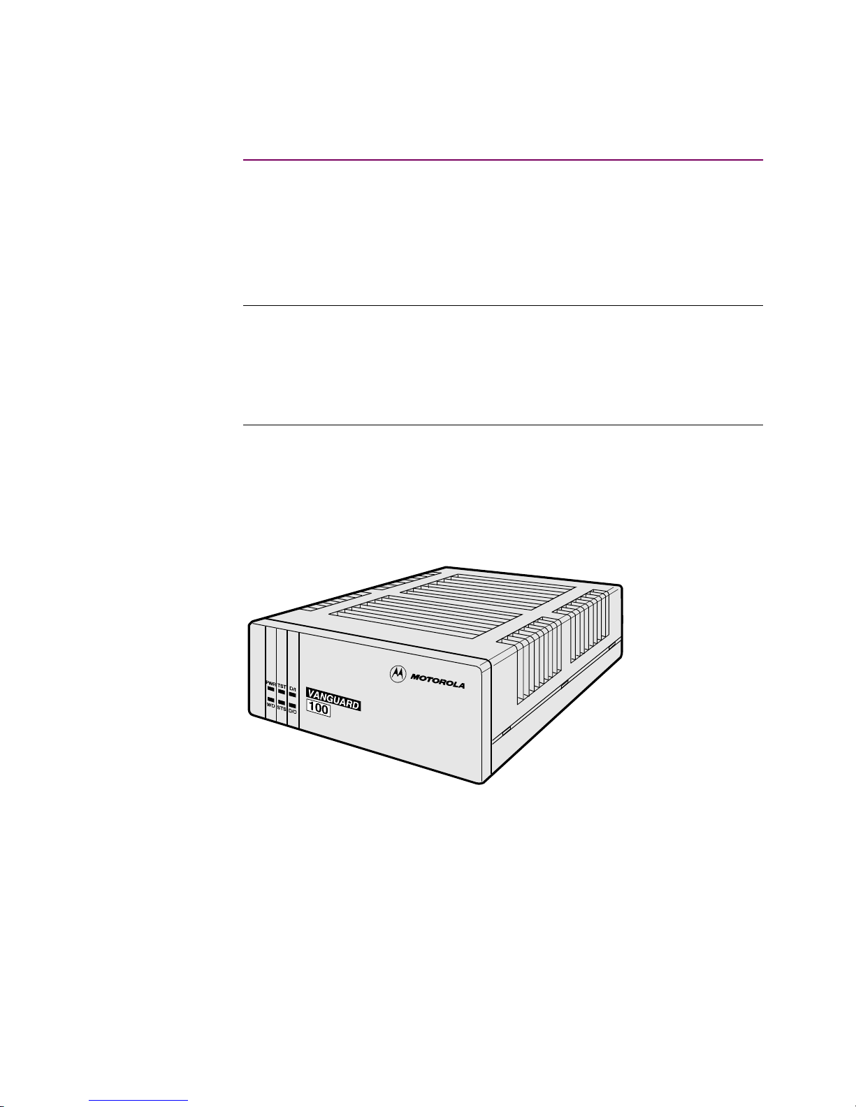
Overview The Motorola Vanguard 100 Frame Relay Access Device (FRAD) connects serial
devices to a Frame Relay network. This FLASH-based Vanguard is available either
with or without an integral DSU daughtercard, DIM Site daughtercard, ISDN
daughtercard, or Voice daughtercard, in a desktop-size standalone enclosure, as
shown in Figure 1-1.
Figure 1-1. Motorola Vanguard 100
The Vanguard 100 can be ordered in mono FRAD or duo FRAD configurations with
either two or three serial ports, respectively.
You can use the optional second port for dial backup or as a second user port,
permitting two applications with different protocols share the same Frame Relay
circuit.
Page 2

1-2 About the Vanguard 100
This
Configuration...
Offers...
mono FRAD DIM Port orderable as V.24, V.35, V.36, or V.11
V. 24 interface
mono FRAD with
DSU
V. 24 interface
DSU daughtercard interface
duo FRAD DIM Port orderable as V.24, V.35, V.36, or V.11
DIM Site daughtercard interface
V. 24 interface
duo FRAD with
DSU
DIM Port orderable as V.24, V.35, V.36, or V.11
V. 24 interface
DSU daughtercard
Page 3

About the Vanguard 100 1-3
Features
Features
Standard Feature
Set
The Motorola Vanguard 100 base unit includes the following standard feature set:
• X.25 Service
• Frame Relay Service
• Asynchronous Protocol
• Transparent Polled Asynchronous Protocol
• Simple Network Management P rotocol
• Trivial File Transfer Protocol
Software Bundles Vanguard 100 offe rs multipro toc ol access, t hat runs a variet y of prot ocols dep ending
on which software bundle you choose. Information about the available software
bundles appears in the software release notice for the currently shipping software
release.
DSU Functionality The DSU daughtercard provides a 56 kbps point-to-point DDS1 interface that
conforms to the AT&T 62310 or ANSI T1E1.4/91-006 standards.
The DSU is FCC Part 68-registered.
Diagnostic loopback s fr om the telephone company are supported. You activate local
diagnostics from the Con trol Terminal Port (CTP).
CTP Manageability You can manage the Motorola Vanguard 100 from the CTP for configuration,
reporting, and troubleshooting.
Vanguard 100 is available in two and three serial port versions. Ports have the
following characteristics.
Port Characteristics
Port Connector Interface Default Speed DTE/
DCE
1 V.24: DB25 DIM Site D/C Frame
Relay
115.2 kbps (async)
80 kbps (sync)
DCE
DSU: RJ48S DSU D/C Frame
Relay
56 kbps (sync) NA
2 DB25 DIM on
motherboard
Frame
Relay
V.24:
• 80 kbps (sync)
• 115.2 kbps
(async)
V.35, V.11, or V.36:
• 384 kbps int.
clocks
• 1.54 Mbps ext.
clocks
Selectable
3 V.24: DB25 Motherboard Async 115.2 kbps (async)
80 kbps (sync)
DCE
Page 4

1-4 About the Vanguard 100
Features
Memory The board contains 1 Mbyte of FLASH memory and 2 Mbytes of DRAM.
Default Report Log
Size
On software releases prior to 4.35, 140 data buffers were allocated for reports, for a
total of 200 reports.
For the 4.35 software, 10 data buffers are allocated for reports, for a total of 20
reports that can be logged on the Vanguard 100, thereby saving 130 data buffers.
There is no additional configuration required to recover these buffers.
Support for 57.6
Kbps
The SLIP and PAD ports on the Vanguard 100 now support a baud rate of 57.6 kbps.
Note
The 6525 and Vanguard 200 do not support 57.6 kbps.
Page 5

About the Vanguard 100 1-5
Memory DRAM Recovery
Memory DRAM Recovery
Introduction On software prior to Release 4.35, 65 kilobytes was allocated for configuration
memory size internally, which is identical to the allo tment for the 6525.
For the Vanguard 100, 65 kilobytes is unnecessary, since configuration memory si ze
is only 8 kilobytes.
The software has changed to use some of this memory for new protocols. Vanguard
configuration memory is reduced to 16 kilobytes, saving approximately 220 data
buffers or 48 kilobytes of RAM.
Recovery
Conditions
Consult the following table concerning conditions for memory resource recovery.
Recovery
Procedure
Use the following procedure to recover memory DRAM.
If... Then...
You purchased a node with 4.35
software already installed
No upgrade is required
The first page of the Node Stats
Record shows the decompressed
configuration memory ( DRAM) to be
16384 bytes
No upgrade is required
Release 4.23 software is running Use one of these two options:
• Take no action: the Release 4.35
functions with the 65 kilobyte
configuration memory size that
Release 4.23 initially set up
• Upgrade the node to recover
memory DRAM
Step Action
1
Save your configuration memory using a TFTP or kermit transfer.
2
Default th e node CMEM using the Control Terminal Port.
(i.e., entry 13 in the Main menu).
3
Restore the saved configu ration memor y. (Booting the node is not
necessary.)
Page 6

1-6 About the Vanguard 100
Pre-Installation Procedures
Pre-Installation Procedures
Site Preparation Ensure that the select ed site i s free of a ccumulated dust and environmental extremes.
Caution
All Motorola Vanguard 100 devices should be used in environments designed for
computers and electronic equipment. In areas susceptible to lightning, take
precautions to prevent damage to electronic equipment. Contact your telephone
company, or an electronic accessories vendor, for information on lightning
protection equipment.
Power Source Choose a site that is within an ap propri ate di stance of a power source. Depending on
your application and the country in which you operate the Motorola Vanguard 100,
this must be a grounded 100 to 240 VAC outlet.
Warnings and
Cautions
The following special notices apply to all equipment handling procedures in this
operator’s guide.
Warning
Motorola Vanguard 100 daughtercards and DIMs are sensitive to electro-static
discharge, which can damage components. Only trained, qualified technicians
should perform procedures outlined in this guide to ensure proper handling and
grounding procedures.
Connecting Ports
Warning
Ports that are capable of connecting to other apparatus are defined as SELV. To
ensure conformity with the EN60950 standard - check that these ports are only
connected to ports of the same type on other apparatus.
Attention
Les ports qui sont susceptibles d’être connectés à des équipements sont désignés
comme TBTS. Pour garantir la conformité à la norme EN 60950, n’interconnecte
ces ports qu’avec des ports du même type sur des autres matériels.
Achtung
Anschlusse, die mit anderen Geraten verbindet werden konnen, sind als SELV
beschrieben. Um Konformita t mi t EN 60950 zu versichern, sichern Sie es, daß di es e
Anschlusse nur mit den des selben Type auf anderen Geraten verbindet werden.
Page 7

About the Vanguard 100 1-7
Pre-Installation Procedures
Cable Clearance/
Air Circulation
Allow at least 12 in ches ( 30.5 cm) in bac k of the unit f or ai r circ ulati on and i nt erf ace
cable clearance. Refer to Figure 1-2.
Caution
To avoid overheating the unit’s circuitry, never place anything:
• On top of the unit,
• Within 1 inch (2.5 cm) of the ventilation slots on the front panel, or
• Within 12 inches (30.5 cm) of the back of the unit.
Figure 1-2. Proper Cable and Air Clearance
Minimum
12 inches
(30.5 cm)
Do Not Place
Anything on Top
of the Unit
Page 8
1-8 About the Vanguard 100
Pre-Installation Procedures
Unpacking
Vanguard 100
Package Contents
Motorola Vanguard 100 is packaged in shock-absorbent packing material with the
following items:
• Base unit
•Manual
• NEMA 5-115 power cord (if ordered)
• Telco cable for DSU
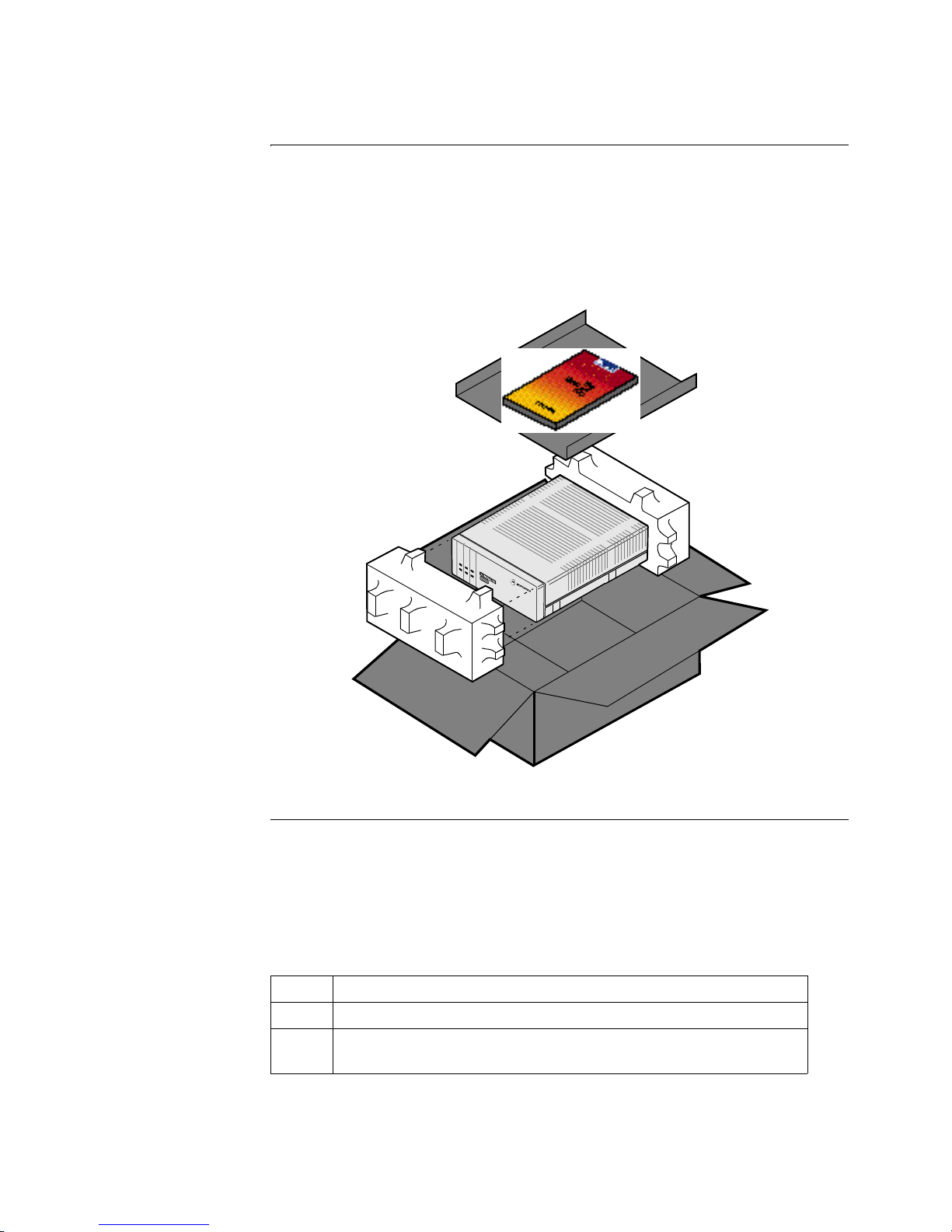
Figure 1-3. Unpacking the Motorola Vanguard 100
When You Receive
Your Vanguard 100
Vanguard 100 components are factory installed in the base unit. In addition to the
base unit and accompanying components, the shipping carton may include a sleeve
containing the power cord.
Upon receipt of the Motorola Vanguard 100, check the contents of the shipping
container as follows.
Step Action
1
Check the shipping carton and its contents for damage.
2
Lift the Vanguard 100 from its shipping carton and remove the
packing material.
Page 9

About the Vanguard 100 1-9
Pre-Installation Procedures
In Case of Damage If the equipment is damaged in transit, contact the shipper.
If you have additional concerns in case of failure, about missing parts, or to return
equipment, contact your nearest Motorola ISG representative.
Cables For cablin g information, refer to C hapter 3 in the Vanguard 6520 Installation Guide.
DSU Telco Cable The DSU telco cable is unshielded twisted-pair 19 to 26 AWG. The DSU cable is
shipped with the DSU daughtercard.
The DSU cable has an RJ48S (keyed 8 position jack) and terminates in RJ48S plugs
at both ends
Attach cables to the Vanguard 100’s rear panel connections as follows.
For Locations... Contact...
Inside the United States Motorola ISG
Customer Administrati on
20 Cabot Blvd.
Mansfield, MA 02048-1193
Phone (508) 261-4000, Ext. 4745
Outside the United
States
Nearest Motorola ISG distributor
Step Action
1
Connect the power cables.
2
Connect the interface cables.
3
Connect the DTE cable.
4
Connect the power cord to the prim ary power source.
Page 10

1-10 About the Vanguard 100
FCC Part 68 and Telephone Company Procedures and Requirements for DSU
FCC Part 68 and T elephone Company Pr ocedures and
Requirements for DSU
Before You Begin Before the Motorola Vanguard 100 can be connected to the network, you must:
• Provide the local telephone company with the equipment’s registration
number
• Order the proper connections
How to Order
Connections
To order the proper connections, provide the telephone company with the following
information:
• Interface type
• Required USOC jack connector number
• Service code
• Facility interface cod es
Troubleshooting
Your Connection
If any of your equipment is not operating correctly, immediately remove it from the
telephone line before damaging the network. If the telephone company is aware of
the problem, they may temporarily disconnect your service. Whenever possible, the
telephone company notifies you in advance of the disconnection.
If advance notice is not feasible, you are notified as soon as possible. Once notified,
you can correct the problem. If nece ss ary, it is your right to file a complaint with the
FCC.
Customer-Provided
Telephone
Equipment
FCC regulations and telephone company procedures prohibit connection of
customer-provided equipment to telephone company-provided coin service (central
office-implemented systems). Connection to party lines is subject to state tariffs.
Occasionally, the telephone company may make changes in their equipment,
operations, or procedures. If these changes can affect your equipment or service, the
telephone company provides written notice so that you can make the necessary
changes to maintain uninterrupted service.
Contact your telephone company if you have any questions about your telephone
line.
In some circumstances, the telephone company may ask you for information about
the equipment tha t is co nnected to the telephon e line. W ithi n the United St ates (a t the
request of the telephone company), you should provide your equipment’s FCC
registration number. This number is located on the unit’s label.
Interface Type USOC Jack
Connector
Service
Code
Facility Interface
Code
56-kbps digital interface RJ48S 6.0F 04DU5-56
 Loading...