

PRELIMINARY DRAFT
Motorola Satellite Series 9522
L-Band Transceiver
Fact Sheets
. SHEET
1

PRELIMINARY DRAFT
Motorola Satellite Series 9522
L-Band Transceiver
Fact Sheets
1 Product Overview
The 9522 LBT is intended for incorporation into a final Iridium subscriber product that would supply power,
provide an antenna, and provide user interface components such as a keypad, display, microphone, and speaker. If
the final product supports a data mode, an RS232 data interface would also be included.
Regulatory approval for FCC, Canada and CE will be provided for the 9522 LBT assuming an antenna with a gain
of ≤3 dBi. This will allow the 9522 LBT to be integrated into a variety of subscriber products, as well as retrofitted
into existing LBT-based subscriber products. These products, when integrated together will require Regulatory
testing.
The functional capabilities of the 9505 handset provide the baseline for the 9522 LBT, noting that user interface
components must be added to the 9522 LBT in order to access such functionality. The ISU AT Command
Reference and the Satellite Series 9505 Portable Telephone User’s Guide provide information relevant to the 9522
LBT’s functional capabilities.
The following differences exist when comparing the functional capabilities of the 9522 LBT to the 9505 handset.
• The 9522 LBT is always powered externally and therefore has no battery metering.
• The 9522 LBT does not incorporate a vibrating call alert and therefore has no vibrate/ring control.
• The 9522 LBT incorporates an analog audio interface not present on the 9505 handset.
2 Standards Compliance
The 9522 LBT has been designed to comply with the standards for Emissions Compliance, Electromagnetic
Compatibility, Electromagnetic Safety, and AC Safety in the United States, Europe and Canada. Standards in other
areas of the world are often the same.
2.1 FCC Compliance
This device has been certified under 47 CFR Part 25 as FCC ID: IHDT 6NJ1 and also complies with Part 15 of the
FCC Rules. Operation is subject to the condition that this device does not cause harmful interference. Any changes
or modifications, including the use of a non-standard antenna, not expressly approved by the party responsible for
compliance could void the user's authority to operate the equipment.
IMPORTANT: To comply with FCC RF exposure requirements, a minimum separation of 20 cm is required
between the antenna and all persons.
2.2 CE Compliance
This product, when marked with the CE symbol, complies with the European Community Council Directive for
R&TTE, 99/5/EC, provided the installer/user adheres to the instructions detailed in the Interface specification
product is in compliance with applicable ETSI standards. Compliance with the requirements of ETSI EN 301 489
requires the use of a shielded digital data interface cable.
.This
. SHEET
2
PRELIMINARY DRAFT
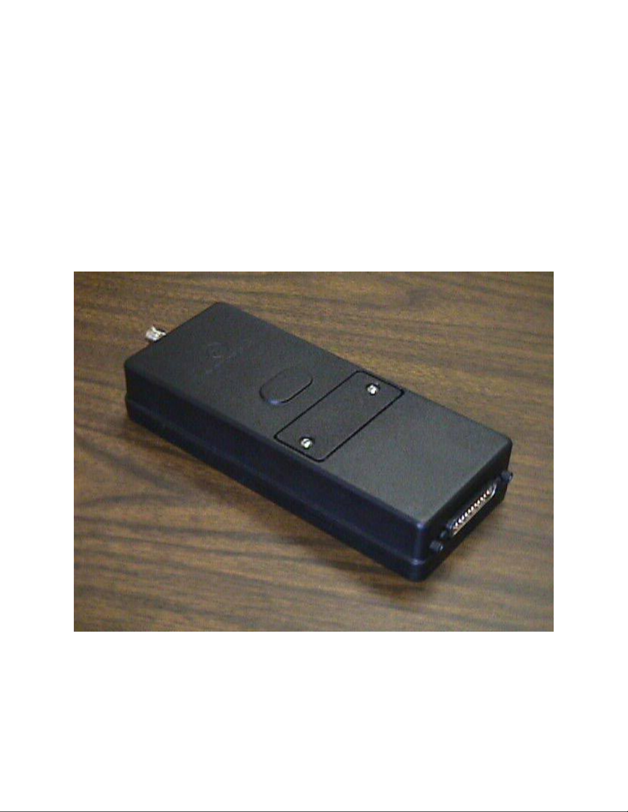
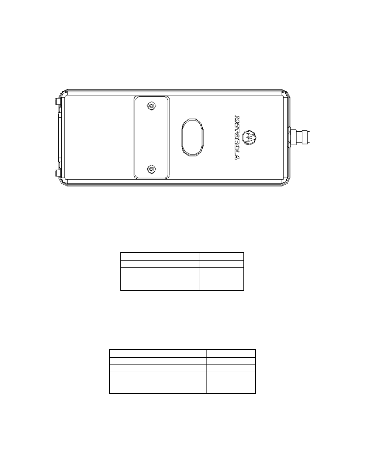
3 Physical Specifications
The 9522 LBT is depicted in Figure 1 below.
Figure 1: Top View
3.1 Environmental
The environmental specifications of the 9522 LBT are summarized in Table 1 below.
Table 1: Environmental Specifications
Parameter Value
Operating Temperature Range -20°C to +60°C
Operating Humidity Range
Storage Temperature Range -40°C to +85°C
Storage Humidity Range
≤ 85% RH
≤ 85% RH
3.2 Dimensions
The overall dimensions of the 9522 LBT and its weight are summarized in Table 2 below. Dimensioned views of
the 9522 LBT are shown in Figures 2-5 to follow.
Table 2: Mechanical Dimensions
Parameter Value
Length (including antenna connector) 216.1 mm (8.51")
Length (excluding antenna connector) 196.4 mm ( 7.73")
Width 82.6 mm (3.25")
Depth 39.0 mm (1.54")
Weight (approximate) 610 g
. SHEET
3

PRELIMINARY DRAFT
Figure 2: Side View
Figure 3: Bottom View
. SHEET
4

PRELIMINARY DRAFT
Figure 4: Antenna Connector End View
Figure 5: Multi-Interface Connector End View
3.3 Interface Connectors
The 9522 LBT incorporates three interface connectors.
• Multi-Interface Connector (located on the end of the 9522 LBT)
• Antenna Connector (located on the end of the 9522 LBT ; opposite to the multi-interface connector)
• Subscriber Identity Module (SIM) Chip Connector (located beneath a cover plate atop the 9522 LBT)
. SHEET
5

PRELIMINARY DRAFT
3.3.1 Multi-Interface Connector
The multi-interface connector is a 25 pin D-sub miniature type that includes four interfaces.
• DC Power
• Control/Audio
• RS232 Data
• Analog Audio
3.3.2 Antenna Connector
The 9522 LBT provides a single, 50 Ω, TNC type antenna connector for both transmit and receive.
3.3.3 SIM Chip Connector
An integrated SIM chip connector is provided on the 9522 LBT. This connector allows installation of the chip form
of the SIM beneath a cover plate on the 9522 LBT housing.
4 Electrical Interfaces
The subsections to follow contain interface information for the electrical interfaces of the 9522 LBT.
4.1 DC Power Interface
4.1.1 DC Power Interface Signal Descriptions
The DC power interface is comprised o f the DC power inputs and a control signal as summarized in Table 3 below.
The EXT_B+ and GND inputs are used to supply DC power to the 9522 LBT. The EXT_ON_OFF control input is
pulled to a GND level to toggle the 9522 LBT on and off.
Table 3: Control/Audio Interface Signal Descriptions
Signal Name Signal Description
EXT_B+ External 4.4 VDC input
GND External GND input
EXT_ON_OFF Power on/off control input
. SHEET
6

PRELIMINARY DRAFT
4.1.2 DC Power Input Specifications
The DC power requirements for the 9522 LBT are summarized in Table 4 below. Note that these requirements
apply to DC power measured at the 9522 LBT multi-interface connector input.
Table 4: DC Power Input Specifications
Parameter Value
Main Input Voltage - Range +4.0 VDC to +4.8 VDC
Main Input Voltage - Nominal 4.4 VDC
Main Input Voltage - Ripple 40 mVpp
Peak Input Current (maximum) 2.5 A @ 4.4 VDC
Main Input Active Power (average) 2500 mW
Main Input Standby Power (average) 210 mW
4.2 Control/Audio Interface
4.2.1 Control/Audio Interface Signal Descriptions
The control/audio interface enables peripherals such as handsets and SIM card readers to be interfaced to the 9522
LBT. The interface utilizes a Motorola Proprietary full duplex communication buss not detailed in this fact sheet.
Details can be made available after appropriate Non-disclosure Agreements and /or License Agreements are
executed.
4.3 RS232 Data Interface
4.3.1 RS232 Data Signal Descriptions
The RS232 data interface is comprised of eight standard RS232 data, control, and status signals plus a ground level
signal reference. This interface allows a connected Data Terminal Equipment (DTE) to utilize the 9522 LBT’s
modem functionality via AT command control.
4.4 Analog Audio Interface
4.4.1 Analog Audio Interface Signal Descriptions
The analog audio interface is comprised of the analog audio input and output signals, an enable input signal, and a
ground level signal reference as summarized in Table 5 below.
Table 5: Analog Audio Interface Signal Descriptions
Signal Name Signal Description
MIC_AUD Analog audio input
SPKR_AUD Analog audio output
ANALOG_AUD_EN Analog audio enable input
ANALOG_GND Analog audio ground level si gnal reference
. SHEET
7

PRELIMINARY DRAFT
4.5 SIM Interface
An integrated SIM chip connector is provided on the 9522 LBT. An external SIM card reader may also be
interfaced as a peripheral to the 9522 LBT via the DSC bus of the control/audio interface. A SIM card in the
external reader will take precedence over the SIM chip in the integrated connector when both are present.
4.6 RF Interface
4.6.1 RF Interface Specifications
The RF interface requirements for the 9522 LBT are summarized in Table 6 belo w.
Table 6: General RF Parameters
Parameter Value
Frequency Range 1616 MHz to 1626.5 MHz
Duplexing Method TDD (Time Domain Duplex)
Oscillator Stability ± 1.5 ppm
Input/Output Impedance
Multiplexing Method TDMA/FDMA
50 Ω
4.6.2 Radio Characteristics
The tables within this section contain radio characteristics of the 9522 LBT.
Table 7: In-Band Characteristics
Parameter Value
Average Power during a transmit slot (max) 7 W
Average Power during a frame (typical) 0.6 W
Receiver Sensitivity at 50 Ω (typical)
Receiver Spurious Rejection at offsets > 1 MHz (typical) 60 dB
Table 8: Link Margin
Configuration Cable Loss LinkMargin
9522 LBT with Motorola accessory antennas (Note 1) 2 dB (Note 2) 13.1 dB (Note 3)
Note 1: Other antenna options may become available
Note 2: Cable losses should be minimized
Note 3: Link Margin given for free space
-118.5 dBm
. SHEET
8
 Loading...