

Page 1
RS419
RING SCANNER
QUICK REFERENCE GUIDE
Page 2

Zebra reserves the right to make changes to any product to improve reliability, function, or design.
Zebra does not assume any product liability arising out of, or in connection with, the application or
use of any product, circuit, or application described herein.
No license is granted, either expressly or by implication, estoppel, or otherwise under any patent
right or patent, covering or relating to any combination, system, apparatus, machine, material,
method, or process in which Zebra products might be used. An implied license exists only for
equipment, circuits, and subsystems contained in Zebra products.
Warranty
For the complete Zebra hardware product warranty statement, go to:
http://www.motorolasolutions.com/warranty.
Service Information
If you have a problem using the equipment, contact your facility’s Technical or Systems Support. If
there is a problem with the equipment, they will contact the Zebra Global Customer Support Center
at: http:www.motorolasolutions.com/support.
For the latest version of this guide go to: http://www.motorolasolutions.com/support.
Page 3
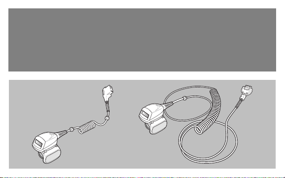
Introduction
The RS419 ring scanner is a modular, wearable laser scanner that allows the operator hands-free bar
code scanning capability. The scanner is used with the WT4090 and WT41N0 wearable terminal.
The RS419 is worn on the operator’s index finger, and utilizes a thumb-operated trigger. The
RS419 connects via an interface cable to the wearable terminal, which provides power and
performs the data collection functions. The RS419 is available in two configurations; a short cable
version for connection to a wrist mounted wearable terminal, and a long cable version for
connection to a hip mounted wearable terminal.
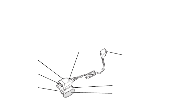
Scan LED
Scan Assembly
Exit Window
Connector
Finger
Strap
Trigger Assembly
Scan Trigger
Short Cable Version Shown
Page 4
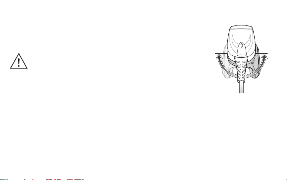
Changing Trigger Position
The trigger assembly of the RS419 rotates to provide left-hand or right-hand
use.
1. Determine whether the RS419 is used on the right or left hand.
CAUTION The trigger assembly only rotates 180° around the
2. Rotate the trigger assembly so that the scan trigger is positioned next to
the thumb when the RS419 is placed on the index finger.
back of the scan assembly. Do not rotate the trigger
assembly past the designed stops.
Installation
The RS419 connects to the wearable terminal and mounts on the index finger.
1. On the wearable terminal, remove the connector cap.
2. Connect the RS419 interface cable to the wearable terminal interface connector. If connecting
to a wrist mounted wearable terminal, connect to the interface connector closest to the wrist.
Page 5
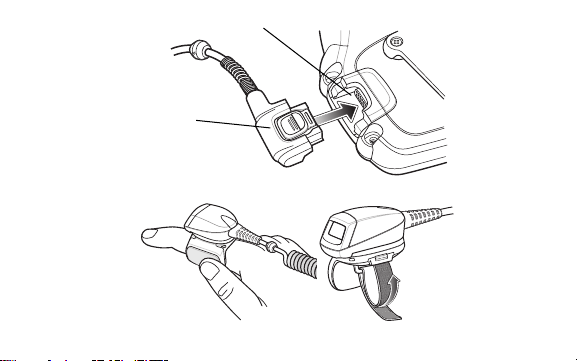
Interface Connector
Scanner
Cable
Connector
3. Slide the RS419 onto the index finger with the scan trigger next to the thumb.
4. Tighten the finger strap.
Page 6
5. If required, cut excess finger strap material.
6. Warm boot the wearable terminal.
Using the Scanner
Not to be used in condensing environments.
To scan bar codes:
1. Turn on the wearable terminal.
2. Launch a scanning application.
3. Press the scan trigger and aim the RS419 at a bar code.
The scan LED lights red to indicate the laser is on.
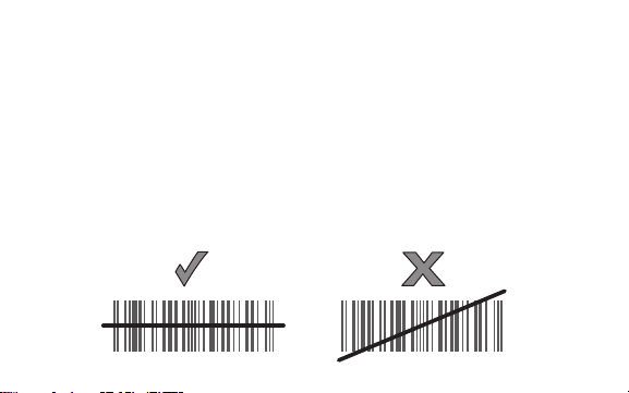
4. Position the red laser beam so that it covers the entire length of the bar code.
Page 7

5. If the decode is successful the LED turns green. The terminal beeps if programed accordingly.
Scanning Tips
• For larger bar codes, hold the RS419 farther away from the bar code.
• For bar codes with bars that are closer together, hold the RS419 closer to the bar code.
• The optimal scanning distance varies with bar code density, but 10 to 25 cm (4 to 10 inches)
generally works. Practice to determine what distances to work within.
• Do not position the RS419 exactly perpendicular to the bar code being scanned. In this
position, reflected light can bounce back into the exit window, and possibly prevent a
successful decode.
Finger Strap Assembly Replacement
The finger strap assembly can be changed for each user or for replacement. To replace the finger
strap assembly:
1. Press down on the finger strap assembly release tab.
Page 8
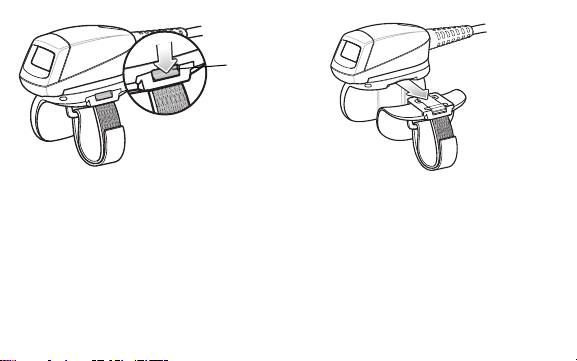
Release Tab
2. Slide the finger strap assembly out of the trigger assembly.
3. Align a new finger strap assembly with the slot in the trigger assembly.
4. Push the finger strap assembly into the trigger assembly until the release tab clicks into place.
5. Insert your index finger through the finger strap. Tighten the strap and press the hook and pile
together.
6. If required, cut excess finger strap material.
Page 9

Replacing the Trigger Assembly
To replace the trigger assembly:
1. Remove the finger strap assembly.
2. Turn the RS419 upside-down.
3. Remove the set screw with
screwdriver.
4. Turn the trigger assembly
counter-clockwise until the exit
window and scan trigger align.
5. Lift the trigger assembly off the scan
assembly.
6. Align replacement trigger assembly
with scan assembly.
7. Rotate trigger assembly 1/4 turn
clockwise.
8. Tighten the set screw with
screwdriver.
9. Replace finger strap assembly.
Page 10

Cleaning
CAUTION Always wear eye protection.
WARNING! AVOID EXPOSING THIS PRODUCT TO CONTACT WITH HOT OIL
Approved Cleanser Active Ingredients
100% of the active ingredients in any cleaner must consist of one or some combination of the
following: isopropyl alcohol, bleach/sodium hypochlorite, hydrogen peroxide or mild dish soap.
Harmful Ingredients
The following chemicals are known to damage the plastics on the RS419 and should not come in
contact with the device: ammonia solutions, compounds of amines or ammonia; acetone; ketones;
ethers; aromatic and chlorinated hydrocarbons; acqueous or alcoholic alkaline solutions;
ethanolamine; toluene; trichloroethylene; benzene; carbolic acid and TB-lysoform.
Read warning label on compressed air and alcohol product before using.
If you have to use any other solution for medical reasons please contact
Zebra for more information.
OR OTHER FLAMMABLE LIQUIDS. IF SUCH EXPOSURE OCCURS,
UNPLUG THE DEVICE AND CLEAN THE PRODUCT IMMEDIATELY
IN ACCORDANCE WITH THESE GUIDELINES.
Page 11

Cleaning Instructions
Do not apply liquid directly to the RS419. Dampen a soft cloth or use pre-moistened wipes. Do not
wrap the device in the cloth or wipe, but gently wipe the unit. Be careful not to let liquid pool around
the display window or other places. Allow the unit to air dry before use.
Special Cleaning Notes
Many vinyl gloves contain phthalate additives, which are often not recommended for medical use
and are known to be harmful to the housing of the RS419. The RS419 should not be handled while
wearing vinyl gloves containing phthalates, or before hands are washed to remove contaminant
residue after gloves are removed. If products containing any of the harmful ingredients listed above
are used prior to handling the RS419, such as hand sanitizer that contain ethanolamine, hands
must be completely dry before handling the RS419 to prevent damage to the plastics.
Materials Required
• Alcohol wipes
• Lens tissue
• Cotton tipped applicators
• Isopropyl alcohol
• Can of compressed air with a tube.
Page 12

Cleaning the RS419
Housing
Using the alcohol wipes, wipe the housing.
Exit Window
Wipe the scanner exit window periodically with a lens tissue or other material suitable for cleaning
optical material such as eyeglasses.
Connector
1. Disconnect the RS419 from the WT41N0.
2. Dip the cotton portion of the cotton tipped applicator in isopropyl alcohol.
3. Rub the cotton portion of the cotton tipped applicator back-and-forth across the connector. Do
not leave any cotton residue on the connector.
4. Repeat at least three times.
5. Use the cotton tipped applicator dipped in alcohol to remove any grease and dirt near the
connector area.
6. Use a dry cotton tipped applicator and repeat steps 4 through 6.
Page 13

CAUTION Do not point nozzle at yourself and others, ensure the nozzle or tube is
7. Spray compressed air on the connector area by pointing the tube/nozzle about ½ inch away
from the surface.
8. Inspect the area for any grease or dirt, repeat if required.
away from your face.
Cleaning Frequency
The cleaning frequency is up to the customer’s discretion due to the varied environments in which
the mobile devices are used. They may be cleaned as frequently as required. However when used
in dirty environments it may be advisable to periodically clean the scanner exit window to ensure
optimum scanning performance.
Page 14

Troubleshooting
Symptom Probable Cause Action
Laser beam
does not
display when
pressing the
trigger.
RS419 does
not decode a
bar code.
Interface cable is not secure. Verify that the interface cable connection is
Power is not applied to RS419. Power for the RS419 is provided by the
Scan enabled application on the
wearable terminal is not running.
Bar code is unreadable. Verify that the bar code is not defective, i.e.,
Exit window is dirty. Clean exit window with a lens tissue. Tissues
Symbology is not enabled. See your system administrator.
connected properly.
wearable terminal. Verify that the wearable
terminal has a charged battery installed.
Launch scanning application on the wearable
terminal.
smudged or broken.
for eyeglasses work well. Do not use tissues
coated with lotion.
Page 15

Symptom Probable Cause Action
Condensation
appears on
the inside or
the outside of
the exit
window.
Using the ring scanner in a hot and
humid environment after being in a
freezer environment.
Wipe condensation from exit window with a
soft cloth.
For condensation on the inside, dedicate ring
scanner to freezer or hot and humid
environment. Do not pass between
environments with the same ring scanner.
Ergonomic Recommendations
CAUTION In order to avoid or minimize the potential risk of ergonomic injury follow the
• Reduce or eliminate repetitive motion
• Maintain a natural position
• Reduce or eliminate excessive force
• Keep objects that are used frequently within easy reach
• Perform tasks at correct heights
• Reduce or eliminate vibration
• Reduce or eliminate direct pressure
recommendations below. Consult with your local Health & Safety Manager to
ensure that you are adhering to your company’s safety programs to prevent
employee injury.
Page 16

• Provide adequate clearance
• Provide a suitable working environment
• Improve work procedures.
Regulatory Information
This device is approved under Symbol Technologies, Inc., a Zebra Technologies company.
All Zebra devices are designed to be compliant with rules and regulations in locations they are sold
and will be labeled as required.
Local language translations are available at the following website:
http://www.motorolasolutions.com/support.
Any changes or modifications to Zebra equipment, not expressly approved by Zebra, could void the
user's authority to operate the equipment.
For use only with Zebra approved and UL Listed mobile computers. Zebra approved and UL Listed
accessories and/or Zebra approved and UL Listed/Recognized battery packs.
Laser Devices
Complies with 21CFR1040.10 AND 1040.11 except for deviations pursuant to Laser Notice NO. 50,
dated June 24, 2007 and IEC 60825-1 (Ed. 2.0), EN60825-1: 2007.
The laser classification is marked on one of the labels on the device.
Page 17

Class 1 Laser devices are not considered to be hazardous when used for their intended purpose.
The following statement is required to comply with US and international regulations:
Caution: Use of controls, adjustments or performance of procedures other than those specified
herein may result in hazardous laser light exposure.
Class 2 laser scanners use a low power, visible light diode. As with any very bright light source,
such as the sun, the user should avoid staring directly into the light beam. Momentary exposure to
a Class 2 laser is not known to be harmful.
Radio Frequency Interference Requirements-FCC
Note: This equipment has been tested and found to comply with the limits for
a Class B digital device, pursuant to Part 15 of the FCC rules. These limits
are designed to provide reasonable protection against harmful interference
in a residential installation. This equipment generates, uses and can radiate
Page 18

radio frequency energy and, if not installed and used in accordance with the instructions, may
cause harmful interference to radio communications. However there is no guarantee that
interference will not occur in a particular installation. If this equipment does cause harmful
interference to radio or television reception, which can be determined by turning the equipment off
and on, the user is encouraged to try to correct the interference by one or more of the following
measures:
• Reorient or relocate the receiving antenna
• Increase the separation between the equipment and receiver
• Connect the equipment into an outlet on a circuit different from that to which the receiver is
connected
• Consult the dealer or an experienced radio/TV technician for help.
Radio Frequency Interference Requirements - Canada
This Class B digital apparatus complies with Canadian ICES-003.
Cet appareil numérique de la classe B est conforme à la norme NMB-003 du Canada.
Page 19

Marking and European Economic Area (EEA)
Statement of Compliance
Zebra, hereby, declares that this device is in compliance with all the applicable Directives,
2004/108/EC, 2006/95/EC and 2011/65/EU. A Declaration of Conformity may be obtained from
http://www.motorolasolutions.com/doc.
Japan (VCCI) - Voluntary Control Council for Interference
Class B ITE
ࡇࡢ⨨ࡣࠊሗฎ⌮⨨➼㟁Ἴ㞀ᐖ⮬つไ༠㆟㸦㹔㹁㹁㹇㸧ࡢᇶ‽ᇶ࡙ࡃࢡࣛࢫ % ሗ
ᢏ⾡⨨࡛ࡍࠋࡇࡢ⨨ࡣࠊᐙᗞ⎔ቃ࡛⏝ࡍࡿࡇࢆ┠ⓗࡋ࡚࠸ࡲࡍࡀࠊࡇࡢ⨨ࡀࣛࢪ࢜
ࡸࢸࣞࣅࢪࣙࣥཷಙᶵ㏆᥋ࡋ࡚⏝ࡉࢀࡿࠊཷಙ㞀ᐖࢆᘬࡁ㉳ࡇࡍࡇࡀ࠶ࡾࡲࡍࠋ ྲྀᢅ
ㄝ᭩ᚑࡗ࡚ṇࡋ࠸ྲྀࡾᢅ࠸ࢆࡋ࡚ୗࡉ࠸ࠋ
Korea Warning Statement for Class B ITE
ὤG㦹Gⷸ ㇠G㟝G㣄G㙼G⇨Gⱬ
i ἽGὤὤ
O ᴴ㥉㟝Gⵝ㋕䋩㐔ὤ㣄㣠 P
㢨Gὤὤ⏈Gᴴ㥉㟝 Oi Ἵ PG㤸㣄䑀㤵䚝ὤὤ⦐㉐G㨰⦐Gᴴ㥉㜄㉐G㇠㟝䚌
⏈Gᶷ㡸G⯝㤵㡰⦐G䚌⮤ SG⯜☔G㫴㜡㜄㉐G㇠㟝䚔G㍌G㢼㏩⏼␘ U
Page 20

Taiwan Statement
R32626
ᲄ☞ᤲᥥჾ
ᆺྕ RS419
ቚすဪไ㐀
Waste Electrical and Electronic Equipment
(WEEE)
English: For EU Customers: All products at the end of their life must be returned to Zebra for recycling. For
information on how to return product, please go to: http://www.motorolasolutions.com/recycling/weee.
Français: Clients de l'Union Européenne: Tous les produits en fin de cycle de vie doivent être retournés à
Zebra pour recyclage. Pour de plus amples informations sur le retour de produits, consultez :
http://www.motorolasolutions.com/recycling/weee.
Español: Para clientes en la Unión Europea: todos los productos deberán entregarse a Zebra al final de su
ciclo de vida para que sean reciclados. Si desea más información sobre cómo devolver un producto, visite:
http://www.motorolasolutions.com/recycling/weee.
Bulgarish: За клиенти от ЕС: След края на полезния им живот всички продукти трябва да се връщат
на Zebra за рециклиране. За информация относно връщането на продукти, моля отидете на адрес:
http://www.motorolasolutions.com/recycling/weee.
Page 21

Deutsch: Für Kunden innerhalb der EU: Alle Produkte müssen am Ende ihrer Lebensdauer zum Recycling
an Zebra zurückgesandt werden. Informationen zur Rücksendung von Produkten finden Sie unter
http://www.motorolasolutions.com/recycling/weee.
Italiano: per i clienti dell'UE: tutti i prodotti che sono giunti al termine del rispettivo ciclo di vita devono
essere restituiti a Zebra al fine di consentirne il riciclaggio. Per informazioni sulle modalità di restituzione,
visitare il seguente sito Web: http://www.motorolasolutions.com/recycling/weee.
Português: Para clientes da UE: todos os produtos no fim de vida devem ser devolvidos à Zebra para
reciclagem. Para obter informações sobre como devolver o produto, visite:
http://www.motorolasolutions.com/recycling/weee.
Nederlands: Voor klanten in de EU: alle producten dienen aan het einde van hun levensduur naar Zebra te
worden teruggezonden voor recycling. Raadpleeg http://www.motorolasolutions.com/recycling/weee voor
meer informatie over het terugzenden van producten.
Polski: Klienci z obszaru Unii Europejskiej: Produkty wycofane z eksploatacji nale¿y zwróciæ do firmy Zebra
w celu ich utylizacji. Informacje na temat zwrotu produktów znajduj¹ siê na stronie internetowej
http://www.motorolasolutions.com/recycling/weee.
Čeština: Pro zákazníky z EU: Všechny produkty je nutné po skonèení jejich životnosti vrátit spoleènosti
Zebra k recyklaci. Informace o zpùsobu vrácení produktu najdete na webové stránce:
http://www.motorolasolutions.com/recycling/weee.
Eesti: EL klientidele: kõik tooted tuleb nende eluea lõppedes tagastada taaskasutamise eesmärgil Zebra'ile.
Lisainformatsiooni saamiseks toote tagastamise kohta külastage palun aadressi:
http://www.motorolasolutions.com/recycling/weee.
Magyar: Az EU-ban vásárlóknak: Minden tönkrement terméket a Zebra vállalathoz kell eljuttatni
újrahasznosítás céljából. A termék visszajuttatásának módjával kapcsolatos tudnivalókért látogasson el a
http://www.motorolasolutions.com/recycling/weee weboldalra.
Page 22

Slovenski: Za kupce v EU: vsi izdelki se morajo po poteku življenjske dobe vrniti podjetju Zebra za reciklažo.
Za informacije o vraèilu izdelka obišèite: http://www.motorolasolutions.com/recycling/weee.
Svenska: För kunder inom EU: Alla produkter som uppnått sin livslängd måste returneras till Zebra för
återvinning. Information om hur du returnerar produkten finns på
http://www.motorolasolutions.com/recycling/weee.
Suomi: Asiakkaat Euroopan unionin alueella: Kaikki tuotteet on palautettava kierrätettäväksi Zebra-yhtiöön,
kun tuotetta ei enää käytetä. Lisätietoja tuotteen palauttamisesta on osoitteessa
http://www.motorolasolutions.com/recycling/weee.
Dansk: Til kunder i EU: Alle produkter skal returneres til Zebra til recirkulering, når de er udtjent. Læs
oplysningerne om returnering af produkter på: http://www.motorolasolutions.com/recycling/weee.
Ελληνικά: Για πελάτες στην Ε.Ε.: Όλα τα προϊόντα, στο τέλος της διάρκειας ζωής τους, πρέπει να
επιστρέφονται στην Zebra για ανακύκλωση. Για περισσότερες πληροφορίες σχετικά με την επιστροφή ενός
προϊόντος, επισκεφθείτε τη διεύθυνση http://www.motorolasolutions.com/recycling/weee στο Διαδίκτυο.
Malti: Għal klijenti fl-UE: il-prodotti kollha li jkunu waslu fl-aħħar tal-ħajja ta' l-użu tagħhom, iridu jiġu rritornati
għand Zebra għar-riċiklaġġ
http://www.motorolasolutions.com/recycling/weee.
Românesc: Pentru clienţii din UE: Toate produsele, la sfârşitul duratei lor de funcţionare, trebuie returnate
la Zebra pentru reciclare. Pentru informaţii despre returnarea produsului, accesaţi:
http://www.motorolasolutions.com/recycling/weee.
Slovenčina: Pre zákazníkov z krajín EU: Všetky výrobky musia byť po uplynutí doby ich životnosti vrátené
spoločnosti Zebra na recykláciu. Bližšie informácie o vrátení výrobkov nájdete na:
http://www.motorolasolutions.com/recycling/weee.
Lietuvių: ES vartotojams: visi gaminiai, pasibaigus jų eksploatacijos laikui, turi būti grąžinti utilizuoti į
kompaniją „Zebra“. Daugiau informacijos, kaip grąžinti gaminį, rasite:
http://www.motorolasolutions.com/recycling/weee.
. Għal aktar tagħrif dwar kif għandek tirritorna l-prodott, jekk jogħġbok żur:
Page 23

Latviešu: ES klientiem: visi produkti pēc to kalpošanas mūža beigām ir jānogādā atpakaļ Zebra otrreizējai
pārstrādei. Lai iegūtu informāciju par produktu nogādāšanu Zebra, lūdzu, skatiet:
http://www.motorolasolutions.com/recycling/weee.
Türkçe: AB Müşterileri için: Kullanım süresi dolan tüm ürünler geri dönüştürme için Zebra'ya iade
edilmelidir. Ürünlerin nasıl iade edileceği hakkında bilgi için lütfen şu adresi ziyaret edin:
http://www.motorolasolutions.com/recycling/weee.
TURKISH WEEE Statement of Compliance
EEE Yönetmeliğine Uygundur
Page 24

Zebra Technologies Corporation
Lincolnshire, IL U.S.A.
http://www.zebra.com
Zebra and the Zebra head graphic are registered trademarks of ZIH Corp. The Symbol logo is a registered
trademark of Symbol Technologies, Inc., a Zebra Technologies company.
© 2014 Symbol Technologies, Inc.
72-158357-02 Rev. A - December 2014
 Loading...