

Page 1

B
STARLINE®
SG4-DRT-2X
Installation Sheet 509978-001
The Motorola® Digital Return Transmitter (SG4-DRT-2X) implements Time Division
Multiplexing (TDM) to convert two, independent 5 to 65 MHz analog RF return-path signals,
into one digital optical signal within SG4000 optical nodes. This digital optical signal with 10-bit
resolution and 3.125 Gbps rate is suitable for optical transmission on the International
Telecommunications Union (ITU) grid to the GX2-DRR-2X Digital Return Receiver (DRR) where
the original analog return-path signals are recreated.
The transmitter is configured with an 8 dBm digital Distributed Feedback (DFBT) laser that is
thermally stabilized to minimize wavelength drift. Multiple ITU wavelengths are available
depending on specific link requirements. The specific ITU channel and frequency are stamped
on the label on each transmitter and are identified in the subsection SG4-DRT-2X Models at the
end of this document.
The SG4-DRT-2X transmitter features high-speed digital technology to achieve reliable return
path communications at greater distances. The system is completely scalable and can be
expanded from a single transmitter/receiver to groups of 4, 8, 16, 32, or 40 wavelengths over a
single fiber with the use of muxing and demuxing equipment. The system is compatible with
Motorola low-noise optical amplifiers (EDFAs), enabling network designs that cover large
geographical areas. Without amplification, the SG4-DRT-2X Dense Wave Division Multiplexing
(DWDM) digital return system is capable of achieving a link loss budget of 26 dB.
The system achieves superior noise power ratio (NPR) and dynamic range (DR) performance in
return path communications. The SG4-DRT-2X system is HMS compliant and features an
enable/fault LED to report local status information. The SG4-DRT-2X comes standard with
SC/APC optical connectors; E2000 adapters are optional.
To facilitate easy upgrades, the double-wide SG4-DRT-2X module has the same set-up levels as
the analog return transmitters and can accomplish any two-transmitter configuration using
only a single fiber.
Figure 1 illustrates a block diagram of the SG4-DRT-2X:
Figure 1
SG4-DRT-2X block diagram
Return
Channel
Input B
5-65 MHz
Te st
Input B
-20 dB
Return
Channel
Input B
5-65 MHz
Te st
Input B
-20 d
JXP Coupler EQ Fiber A/D
JXP
Coupler
FiberEQ
TXF
MR
TXF
MR
A/D
Transmit
Signal
Processing
Mux
Laser
Te st Po in t
Laser
driver
Laser
TEC
Optical
Output
-3 Gbps
SG4-DRT-2X Installation Sheet
Page 2
2 STARLINE
A
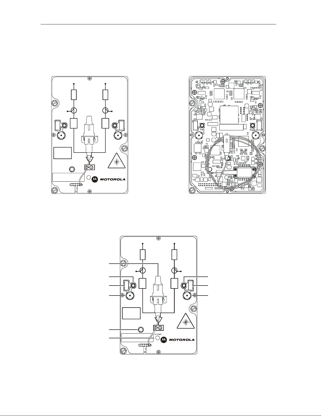
Figure 2 illustrates the SG4-DRT-2X with the cover on (left) and cover off (right):
Figure 2
SG4-DRT-2X transmitter
CH BCH A
-5 dBmV
NOMINAL
TOTAL POWER
INVISIBL E LASER
RADIATION. AVOID
EXPOSURE TO BEAM.
CLASS 3B LASER
PRODUCT.
ENABLE/FAULT
J
X
P
0.5 V/mW
J
X
P
-5 dBmV
NOMINAL
TOTAL POWER
A / DA / D
2X DIGITAL TRANSMITTER
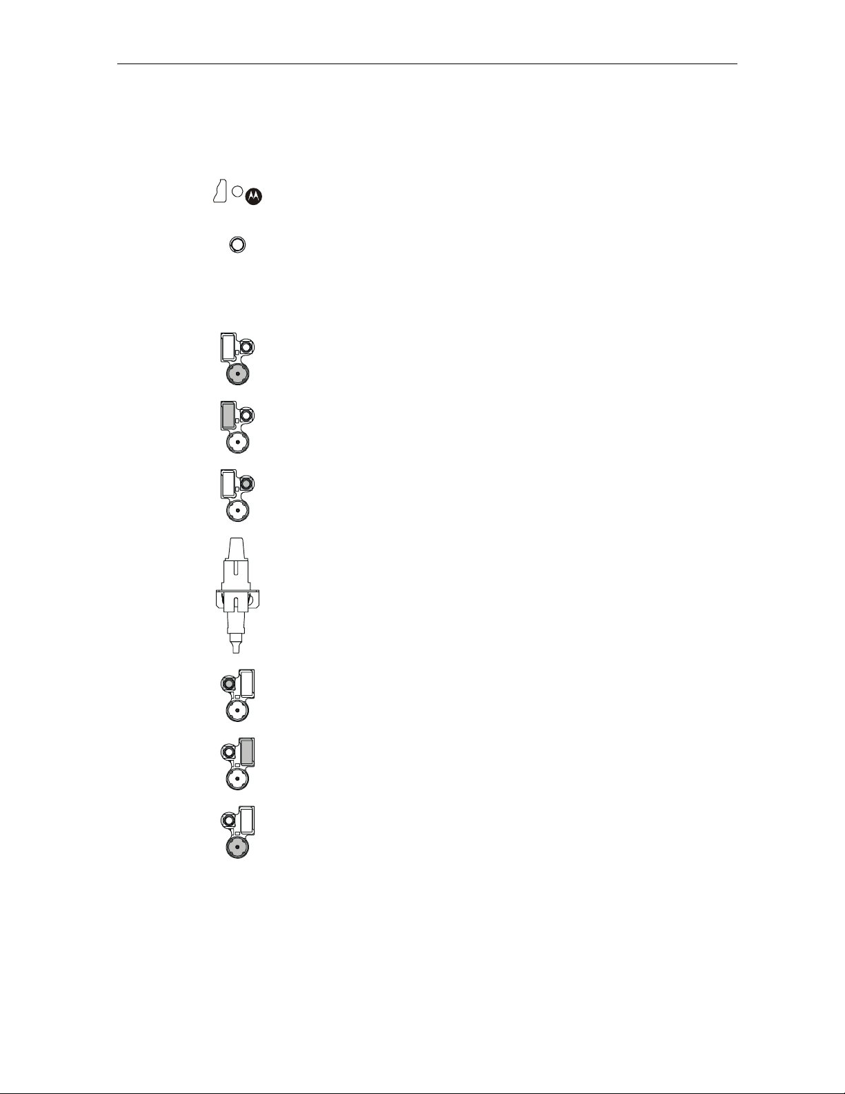
Figure 3 illustrates the user-interface features of the SG4-DRT-2X:
Figure 3
User features
CH BCH A
J
X
P
J
X
P
6
-5 dBmV
NOMINAL
TOTAL POWER
-5 dBmV
NOMINAL
TOTAL POWER
57
48
/ DA / D
39
INVISIBLE LASER
RADIAT ION. AV OI D
EXPOSURE TO BEAM.
CLASS 3B LASER
PRODUCT.
ENABLE/FAULT
2
1
2X DIGITAL TR ANSMITT ER
SG4-DRT-2X Installation Sheet
Page 3
STARLINE 3
Table 1 identifies and provides information on the user-interface features of the SG4-DRT-2X:
Key Feature Description
1
2
3
4
5
0.5 V/mW
ENABLE/FAULT
This test point enables monitoring of the optical output level of the module.
The nominal scale factor is 0.5 V/mW. Note that the optical power test point
does not track changes in optical power due to the laser tracking error.
A red LED (
limits. Because the laser output requires a short period of time to stabilize, it
is normal for the LED not to illuminate for approximately 10 seconds. Note
FAULT) indicates that the laser output power is below normal
that the module must be enabled for the fault indicator to function.
A green LED (
ENABLE) provides visual indication of the transmitter’s enable
status.
CH A RF input test point (−5 dBmV nominal total power)
CH A JXP attenuator location. Used to adjust −5 dBmV nominal total power
reading at
CH A test point.
This MCX connector provides the SG4-DRT-2X with
CH A RF input through a
cable connection from the configuration board in an SG4000.
6
Optical bulkhead with SC/APC type connector that provides output from the
SG4-DRT-2X
7
This MCX connector provides the SG4-DRT-2X with
CH B RF input through a
cable connection from the configuration board in an SG4000.
8
CH B JXP attenuator location. Used to adjust −5 dBmV nominal total power
reading at
CH B test point.
9
CH B RF input test point (−5 dBmV nominal total power)
SG4-DRT-2X Installation Sheet
Page 4
4 STARLINE
Installing the SG4-DRT-2X in the SG4000 Node
The SG4000 carries each RF return path individually to the lid configuration boards and
typically no adjustments to the RF modules in the housing base are necessary.
Before you install the SG4-DRT-2X in the SG4000, ensure that you have the return
configuration boards for the specific application. Simply stated, the SG4-DRT behaves as two
analog transmitters. A single SG4-DRT-2X transmitter supports the split return configuration.
(Note: A single SG-DRT-2X also accommodates combined and combined redundant
configurations, but these applications are not covered in this Installation Sheet). You may place
a single transmitter in optics slots 3 and 4 or 5 and 6 in the SG4000 lid. Dual SG4-DRT-2X
transmitters support split return redundant and segmented configurations. The dual
transmitters occupy slots 3 and 4 and 5 and 6 in the SG4000 lid.
The SG4-DRT-2X transmitter design enables you to install it while the node is in service. The
module’s flat bottom provides an excellent thermal transfer surface and has locating holes that
align with guide pins in the lid of the node.
To install the SG4-DRT-2X:
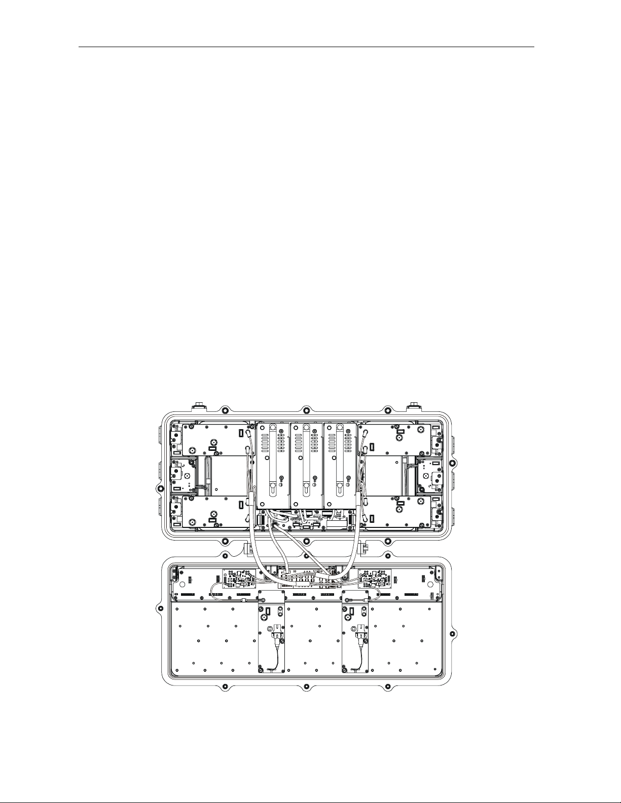
1 If present, remove any analog transmitter that occupies lid optics slots 3 and 4, and/or 5 and
6 in the SG4000 lid as illustrated in Figure 3, and then install the double-wide
SG4-DRT-2X:
Figure 4
SG4000 lid with two analog transmitters
2 Position the SG2-DRT-2X module in the appropriate slot and press gently on the casting
until it is fully seated.
SG4-DRT-2X Installation Sheet
Page 5
STARLINE 5
Tighten the three 1/4 inch mounting bolts to 8 – 12 in/lbs to secure the module in the
3
SG4000 lid.
4 Repeat as required for a second SG4-DRT-2X.
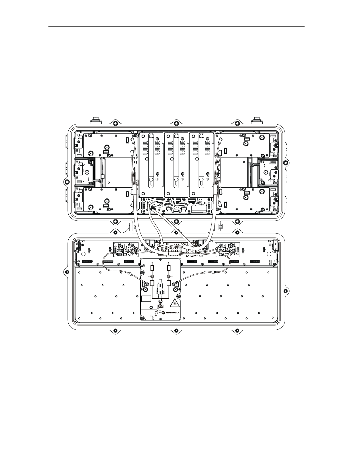
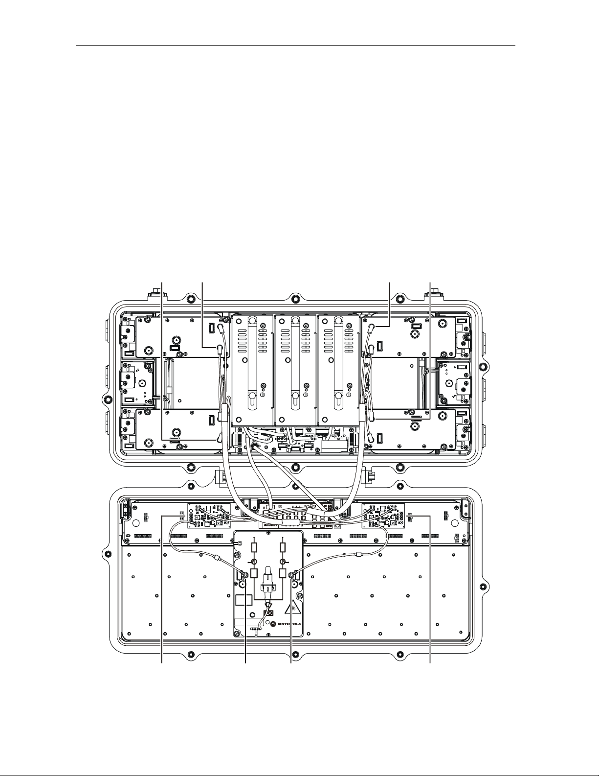
Figure 5 illustrates a properly installed and cabled SG4-DRT-2X:
Figure 5
SG4-DRT-2X installed in SG4000
-5 dBmV
NOMINAL
TOTAL POWER
INVISIBLE LASER
RADIATION. AVOID
EXPOSURE TO BEAM.
CLASS 3B LASER
PRODUCT.
ENABLE/FAULT
CH BCH A
J
J
X
X
P
P
-5 dBmV
NOMINAL
TOTAL POWER
A / DA / D
-5 V/mW
2X DIGITAL TRANSMITTER
SG4-DRT-2X Installation Sheet
Page 6
6 STARLINE
2
Split Return
In the split return configuration, each pair of RF returns is applied to a separate 2X redundant
return configuration board. In a typical installation, the RF modules in Ports 1 and 3 are
connected to the 2X redundant return board in return configuration location 2. The RF modules
in Ports 4 and 6 are connected to the 2X redundant return configuration board in configuration
location 3. The 2X redundant return configuration board, in location 2, directs RF to CH B of the
SG4-DRT-2X. The 2X redundant return configuration board, in location 3, directs RF to CH A of
the SG4-DRT-2X. The same configuration board is used in the split redundant return
configuration explained in the next subsection.
Figure 6 illustrates the split return configuration:
Figure 6
Split return configuration
Port 3 Port 4
Port 1 Port 6
CH BCH A
J
J
X
X
P
P
-5 dBmV
NOMINAL
TOTAL POWER
-5 dBmV
NOMINAL
TOTAL POWER
A / DA / D
INVISIBLE LASER
RADIATION. AVOID
EXPOSURE TO BEAM.
CLASS 3B LASER
PRODUCT.
ENABLE/FAULT
-5 V/mW
2X DIGITAL TRANSMITTER
Split Return
Configuration board
location #3
CH A CH B
Split Return
Configuration board
location #
SG4-DRT-2X Installation Sheet
Page 7

STARLINE 7
Figure 7 illustrates the 2X redundant return configuration board. Jumpers J5 and J6 are shown
in the normal default position. Jumper
J8 (Tx2). Jumper J5 terminates input connector J3 (IN2) when only a single RF input is used.
Figure 7
2X redundant return configuration board
J2
J6 enables/disables signal flow to output connector
J5 J6
C9
IN1IN2
C7
R4
R10
C15
R12
C16
Q1
J9
T3
SM
R2
C3
J1
J4
R1
C18
C1
L1
C2
R16
R13
C4
C5
R11
J8
J7
TX2
T1
J3
C6
TX1
C8
TERM
J5
R3
R8
J6
C12
TERM
C11
R7
C14
C17
R5
C13
R14
C19
R6
C10
R15
T2
Figure 8 illustrates the signal flow through the 2X redundant return board:
Figure 8
2X redundant return board- signal flow
TX2
J6
-3.5 dB
TX1 SM
Loss = 0.9 dB
-0.5 dB
IN2
J5
-3.5 dB
+7.5 dB
IN1
To set up the split return option:
1 Confirm that the SG4-DRT-2X is installed in lid optics slots 3 and 4, or 5 and 6.
2 Confirm that a 2X redundant return board is installed in lid return configuration board
locations 2 and 3 as illustrated in Figure 5.
3 Position J6 in the right-most position to terminate the output to transmitter two.
4 Connect an RF cable from the 2X redundant return board, in lid return configuration board
location 2, to CH B of the SG4-DRT-2X .
5 Connect an RF cable from the 2X redundant return board, in lid return configuration board
location 3, to CH A of the SG4-DRT-2X.
The RF cables should be approximately eight inches long and have red boots on the
connector signifying the return path.
6 If necessary, connect the appropriate return RF cables from the SG4-RF modules to each 2X
redundant board.
SG4-DRT-2X Installation Sheet
Page 8

8 STARLINE
Ensure that the PIC cable is properly connected to the lid and power distribution board in
7
the housing base.
8 Route and connect the fiber service cable.
9 Apply power to the node. Allow five to ten seconds for the system self-diagnosis to complete.
10 Verify that the green LED (ENABLE), located on the top panel of the SG4-DRT-2X is
illuminated to confirm enable status.
11 Measure the RF power at each channels’ test point on the top of the SG4-DRT-2X.
The test point is a −20 dB test point located after the JXP pad location and indicates the
level into the transmitter.
12 Place the proper JXP pad into each channels’ pad facility to achieve the nominal total power
level at the test point of −5 dBmV.
13 Review return path system levels.
The SG4-DRT-2X is configured to drive the laser to the recommended level (+15 dBmV)
when the total combined power at the housing ports connected to the split return board is
approximately (+28 dBmV).
14 Measure the optical power level at the dc test point using a multimeter. The scaled voltage
at this test point is 0.5V/mW.
SG4-DRT-2X Installation Sheet
Page 9

STARLINE 9
A
A
Split Redundant Return
In the split redundant return configuration, each pair of RF returns is applied to a separate 2X
redundant return configuration board. In a typical installation, the RF module in Ports 1 and 3
are connected to the 2X redundant return board in configuration location 2. The RF modules in
Ports 4 and 6 are connected to the 2X redundant return board in configuration location 3. Both
outputs of each 2X redundant board go to the same RF input channel on two different SG4-DRT2X transmitters located in lid optics slots 3 and 4, and 5 and 6.
Figure 9 illustrates the split redundant return configuration:
Figure 9
Split redundant return configuration
Port 3 Port 4
Port 1 Port 6
-5 dBmV
NOMINAL
TOTAL POWER
CH BCH A
J
J
X
X
P
P
-5 dBmV
-5 dBmV
NOMINAL
NOMINAL
TOTAL POWER
TOTAL POWER
A / DA / D
CH BCH A
J
J
X
X
P
P
-5 dBmV
NOMINAL
TOTAL POWER
/ D
/ D
Split Redundant
board location #3
INVISIBLE LASER
RADIATION. AVOID
EXPOSURE TO BEAM.
CLASS 3B LASER
PRODUCT.
ENABLE/FAULT
-5 V/mW
2X DIGITAL TRANSMITTER
CH A CH A
INVISIBLE LASER
RADIATION. AVOID
EXPOSURE TO BEAM.
CLASS 3B LASER
PRODUCT.
ENABLE/FAULT
-5 V/mW
2X DIGITAL TRANSMITTER
CH B CH B
Split Redundant
board location #2
SG4-DRT-2X Installation Sheet
Page 10

10 STARLINE
Figure 10 illustrates the plug-in board required for the 2X redundant return option. Jumpers J5
J6 are shown in the correct position. Jumper J6 enables signal flow to output connector
and
J8 (Tx2) when in the left-most position. Jumper J5 terminates input connector J3 (IN2) when only
a single RF input is used.
Figure 10
2X redundant return board
J5 J6
C9
T1
J3
C6
J2
TX2
J8
J7
TX1
C8
TERM
J5
R3
R8
J6
TERM
C12
C14
C17
R5
C13
R14
C19
R6
C10
R15
C11
R7
T2
IN1IN2
C7
R4
R10
C15
R12
C16
Q1
J9
T3
SM
R2
C3
J1
J4
R1
C18
C1
L1
C2
R16
R13
C4
C5
R11
Figure 11 illustrates the signal flow through the 2X redundant return board:
Figure 11
2X redundant return – signal flow
TX2
J6
-3.5 dB
TX1 SM
Loss = 0.9 dB
-0.5 dB
IN2
J5
-3.5 dB
+7.5 dB
IN1
To set up the split redundant return option:
1 Confirm that SG4-DRT-2X transmitters are installed in lid optics slots 3 and 4, and 5 and 6.
2 Confirm that a 2X redundant return board is installed in return configuration locations 2
and 3 as illustrated in Figure 8.
3 Position J6 in the left-most position on each configuration board to enable the output to Tx2.
4 Connect an RF cable from connector TX1 on the 2X redundant return board in configuration
location 2 to CH B of the transmitter in lid optics slots 3 and 4.
5 Connect a second RF cable from connector TX2 on the 2X redundant return board in
configuration location 2 to CH B of the transmitter in lid optics slots 5 and 6.
6 Connect an RF cable from connector TX1 on the 2X return redundant board in configuration
location 3 to CH A of the transmitter in lid optics slots 3 and 4.
7 Connect a second RF cable from connector TX2 on the 2X return redundant board in
configuration location 3 to CH A of the transmitter in lid optics slots 5 and 6.
SG4-DRT-2X Installation Sheet
Page 11

STARLINE 11
The RF cable should be approximately eight inches long and have red boots on the connector
signifying the return path.
8 If necessary, connect the appropriate return RF cables from the SG4-RF modules to each 2X
redundant return board.
9 Ensure that the PIC cable is properly connected to the lid and power distribution board in
the housing base.
10 Route and connect the fiber service cable.
11 Apply power to the node. Allow five to ten seconds for the system self-diagnosis to complete.
12 Verify that the green LED (ENABLE), located on the top panel of each SG4-DRT-2X is
illuminated to confirm enable status.
11 Measure the RF power at each channels test point on the top of each SG4-DRT-2X.
The test point is a −20 dB test point located after the JXP pad location and indicates the
level into the SG4-DRT-2X.
12 Place the proper JXP pad into each SG4-DRT-2X pad facility to achieve the nominal total
power level at the test point of −5 dBmV.
13 Review return path system levels.
The SG4-DRT-2X is configured to drive the laser to the recommended level (+15 dBmV)
when the total combined power at the housing ports connected to the 2X redundant return
board is approximately +28 dBmV.
14 Measure the optical power level at the dc test point using a multimeter. The scaled voltage
at this test point is 0.5V/mW.
SG4-DRT-2X Installation Sheet
Page 12

12 STARLINE
A
A
2
Segmented Return
In the segmented return configuration each RF return is applied to an individual RF input on
two SG4-DRT-2X transmitters. Two segmented return boards are required. The segmented
return boards contain two independent RF paths. In a typical installation, the RF modules in
Ports 1 and 3 are connected to the segmented return board in return configuration location 2.
The RF modules in Ports 4 and 6 are connected to the segmented return board in return
configuration location 3. The segmented return board installed in return configuration location
2 directs RF to channels A and B on the SG4-DRT-2X located in lid optics slots 3 and 4. The
segmented return board in return configuration location 3 directs RF to channels A and B on the
SG4-DRT-2X located in lid optics slots 5 and 6.
Figure 12 illustrates the segmented return configuration:
Figure 12
Segmented return configuration
Port 1 Port 6Port 3 Port 4
Segmented
Return board
location #3
CH BCH A
J
J
X
X
P
P
-5 dBmV
NOMINAL
TOTAL POWER
INVISIBLE LASER
RADIATION. AVOID
EXPOSURE TO BEAM.
CLASS 3B LASER
PRODUCT.
ENABLE/FAULT
-5 dBmV
-5 dBmV
NOMINAL
NOMINAL
TOTAL POWER
TOTAL POWER
A / DA / D
INVISIBLE LASER
RADIATION. AVOID
EXPOSURE TO BEAM.
CLASS 3B LASER
PRODUCT.
-5 V/mW
2X DIGITAL TRANSMITTER
ENABLE/FAULT
CH A CH A
CH B CH B
CH BCH A
J
J
X
X
P
P
-5 dBmV
NOMINAL
TOTAL POWER
/ D
/ D
-5 V/mW
2X DIGITAL TRANSMITTER
Segmented
Return board
location #
SG4-DRT-2X Installation Sheet
Page 13

STARLINE 13
Figure 13 illustrates the segmented return plug-in board.
Figure 13
Segmented return board
IN2 IN1
J7 J4
SM
C7
R2
R3
R10
R9
R11
C6
J3
R5
C11
R8
R6
R7
C12 C12
C10
R4
J6
TX2
J5
T1
TX1
C1
C2
C9
C3
C8
R1
Figure 14 illustrates the signal flow through the segmented return board:
Figure 14
Segmented return board – signal flow
TX2 IN2
TX1
Loss = 0.9 dB
Pad
-0.5dB
Pad
IN1
SM
To set up the segmented return option:
1 Confirm that dual SG4-DRT-2X return transmitters are installed in lid optics slots 3 and 4
and 5 and 6.
2 Confirm that a segmented return board is installed in the return configuration locations 2
and 3 as illustrated in Figure 11.
3 Connect an RF cable from connector TX1 on the segmented return board in configuration
location 2 to CH B of the SG4-DRT-2X in lid optics slots 3 and 4.
4 Connect an RF cable from connector TX2 on the segmented return board in configuration
location 2 to CH A of the SG4-DRT-2X in lid optics slots 3 and 4.
5 Connect an RF cable from connector TX1 on the segmented return board in configuration
location 3 to CH B of the SG4-DRT-2X in lid optics slots 5 and 6.
6 Connect an RF cable from connector TX2 on the segmented return board in configuration
location 3 to CH A of the SG4-DRT-2X in lid optics slots 5 and 6.
The RF cable should be approximately eight inches long and have red boots on the connector
signifying the return path.
7 If necessary, connect the appropriate return RF cables from the SG4-RF modules to each
segmented return board.
8 Ensure that the PIC cable is properly connected to the lid and power distribution board in
the housing base.
SG4-DRT-2X Installation Sheet
Page 14

14 STARLINE
Route and connect the fiber service cable.
9
10 Apply power to the node. Allow five to ten seconds for the system self-diagnosis to complete.
11 Verify that the green LED (ENABLE), located on the top panel of each SG4-DRT-2X, is
illuminated to confirm enable status.
12 Measure the RF power at each channels test point on the top of each SG4-DRT-2X.
The test point is a −20 dB test point located after the JXP pad location and indicates the
level into the SG4-DRT-2X.
13 Place the proper JXP pad into each channels pad facility to achieve the nominal total power
level at the test point of −5 dBmV.
14 Review return-path system levels.
The SG4-DRT-2X is configured to drive the laser to the recommended level (+15 dBmV)
when the total combined power at the housing ports connected to each leg of the segmented
return board is approximately +28 dBmV.
15 Measure the optical power level at the dc test point using a multimeter. The scaled voltage
at this test point is 0.5 V/mW.
16 Secure all cables and fibers.
17 Close the housing and use a torque wrench to progressively tighten the housing bolts to a
final torque of 12 ft-lbs. in the sequence stamped on the housing lid.
For more specific information regarding return path setup procedures, refer to the supplemental
document Return Path Level Selection, Setup, and Alignment Procedure.
SG4-DRT-2X Installation Sheet
Page 15

STARLINE 15
Specifications
Specifications are valid over the given bandpass and operating temperature range of −40°F to
+140°F (−40°C to +60°C). Specifications are stated typical unless otherwise noted, and are
subject to change. Refer to the Motorola BCS web site or contact your account representative for
the latest specifications.
Parameter Specification
Wavelengths
Wavelength stability
RF bandwidth
Number of input channels
Input level
Input impedance
Input return loss
Output power
Noise Power Ratio
(dB over dynamic range)
Power input
Power consumption
Operating temperature range
Dimensions
Weight
See the following table (SG4-DRT-2X Models)
±0.1 nm maximum
5 MHz to 65 MHz
2
15 dBmV total power
75 ohms
>16 dB
8 dBm
40/13 dB, typical 25°C, 100 km fiber
+24 Vdc
15 W maximum
−40 to +75°C
3.5” (H) × 2” (W) × 6” (D)
1.8 lbs
SG4-DRT-2X Installation Sheet
Page 16

16 STARLINE
SG4-DRT-2X Models
Model Wavelength (nm) Model Wavelength (nm)
SG4-DRT-2X-CH20
SG4-DRT-2X-CH21
SG4-DRT-2X-CH22
SG4-DRT-2X-CH23
SG4-DRT-2X-CH24
SG4-DRT-2X-CH25
SG4-DRT-2X-CH26
SG4-DRT-2X-CH27
SG4-DRT-2X-CH28
SG4-DRT-2X-CH29
SG4-DRT-2X-CH30
SG4-DRT-2X-CH31
SG4-DRT-2X-CH32
SG4-DRT-2X-CH33
SG4-DRT-2X-CH34
SG4-DRT-2X-CH35
SG4-DRT-2X-CH36
SG4-DRT-2X-CH37
SG4-DRT-2X-CH38
SG4-DRT-2X-CH39
1561.65
1560.61
1559.79
1558.98
1558.17
1557.36
1556.56
1555.75
1554.94
1554.13
1553.33
1552.52
1551.72
1550.92
1550.12
1549.32
1548.51
1547.72
1546.92
1546.12
SG4-DRT-2X-CH40
SG4-DRT-2X-CH41
SG4-DRT-2X-CH42
SG4-DRT-2X-CH43
SG4-DRT-2X-CH44
SG4-DRT-2X-CH45
SG4-DRT-2X-CH46
SG4-DRT-2X-CH47
SG4-DRT-2X-CH48
SG4-DRT-2X-CH49
SG4-DRT-2X-CH50
SG4-DRT-2X-CH51
SG4-DRT-2X-CH52
SG4-DRT-2X-CH53
SG4-DRT-2X-CH54
SG4-DRT-2X-CH55
SG4-DRT-2X-CH56
SG4-DRT-2X-CH57
SG4-DRT-2X-CH58
SG4-DRT-2X-CH59
SG4-DRT-2X-CH60
1545.32
1544.53
1543.73
1542.94
1542.14
1541.35
1540.56
1539.77
1538.98
1538.19
1537.40
1536.61
1535.82
1535.04
1534.25
1533.47
1532.68
1531.90
1531.12
1530.33
1529.55
SG4-DRT-2X Installation Sheet
Page 17

STARLINE 17
If You Need Help
If you need assistance while working with the SG4-DRT-2X, contact the Motorola Technical
Response Center (TRC):
Inside the U.S.: 1-888-944-HELP (1-888-944-4357)
Outside the U.S.: 215-323-0044
Motorola Online:
The TRC is open from 8:00 AM to 7:00 PM Eastern Time, Monday through Friday and 10:00 AM
to 5:00 PM Eastern Time, Saturday. When the TRC is closed, emergency service only is
available on a call-back basis. Motorola Online offers a searchable solutions database, technical
documentation, and low priority issue creation/tracking 24 hours per day, 7 days per week.
http://businessonline.motorola.com
SG4-DRT-2X Installation Sheet
Page 18

CAUTION
RISK OF ELECTRIC SHOCK
TO REDUCE THE RISK OF ELECTR IC SHOCK,
CAUTION:
DO NOT REMOVE COVER (OR BACK).
NO USER-SERVICEABLE PARTS INSIDE.
REFER SERVICING TO QUALIFIED SERVICE PERSONNEL .
Caution
These servicing instructions are for use by qualified personnel only. To reduce the risk of electrical shock, do not perform any servicing other
than that contained in the Installation and Troubleshooting Instructions unless you are qualified to do so. Refer all servicing to qualified service
personnel.
Special Symbols That Might Appear on the Equipment
This is a class 1 product that contains a class IIIb laser and is intended for operation in a closed environment
DAN GER
INVIS IBLE LASE R RADIATION
AVOID DIRECT EXPOSURE TO BEAM
PEAK POWER 5.0mW
WAVELENGTH 1300nm
CLASS IIIb LASER PRODUCT
THIS PRODUCT COMPLIES WITH 21CFR
CHAPTER 1 SUBCHAPTER J
with fiber attached. Do not look into the optical connector of the transmitter with power applied. Laser output is
invisible, and eye damage can result. Do not defeat safety features that prevent looking into optical connector.
This product contains a class IIIb laser and is intended for operation in a closed environment with fiber
attached. Do not look into the optical connector of the transmitter with power applied. Laser output is invisible,
and eye damage can result. Do not defeat safety features that prevent looking into optical connector.
For continued protection against fire, replace all fuses only with fuses having the same electrical ratings
marked at the location of the fuse.
MOTOROLA, the Stylized M Logo, and STARLINE are registered in the US Patent & Trademark Office. All other product or service
names are the property of their respective owners. © Motorola, Inc. 2004.
509978-001
8/04
All rights reserved.
No part of the contents of this manual may be reproduced or transmitted in any form or by any means without the
written permission of the publisher.
MGBI
 Loading...