

Page 1
RM Series™/Séries RM™
Two-Way Radios
Radios bidirectionnelles
User Guide
Guide de l’utilisateur
Models RMU 2040, RMM2050 / Modèles RMU2043
Page 2

Open Source Software Legal Notices:
This Motorola product contains Open Source Software. For information regarding
licenses, acknowledgements, required copyright notices and other usage terms,
refer to the documentation for this Motorola product at:
http://businessonline.motorolasolutions.com
Go to: Resource Center > Product Information > Manual > Accessories.
Page 3

CONTENTS
Contents. . . . . . . . . . . . . . . . . . . . . . . . . . . . .1
Product Safety. . . . . . . . . . . . . . . . . . . . . . . .4
Introduction . . . . . . . . . . . . . . . . . . . . . . . . . .5
FCC Licensing Information . . . . . . . . . . . . .7
Canada Licensing Information. . . . . . . . . . .9
Batteries and Chargers
Safety Information. . . . . . . . . . . . . . . . . . . . .8
Operational Safety Guidelines. . . . . . . . . . . . .9
Radio Overview . . . . . . . . . . . . . . . . . . . . . .10
Parts Of The Radio . . . . . . . . . . . . . . . . . . . .10
On/Off/Volume Knob. . . . . . . . . . . . . . . .11
Accessory Connector . . . . . . . . . . . . . . .11
Model Label . . . . . . . . . . . . . . . . . . . . . .11
Microphone . . . . . . . . . . . . . . . . . . . . . . .11
Antenna. . . . . . . . . . . . . . . . . . . . . . . . . .11
LED Indicator . . . . . . . . . . . . . . . . . . . . .11
Side Buttons . . . . . . . . . . . . . . . . . . . . . .11
The Lithium-Ion (Li-Ion) Battery . . . . . . .11
Battery Features . . . . . . . . . . . . . . . . . . . . . .13
About the Li-Ion Battery . . . . . . . . . . . . .13
Battery Recycling and Disposal . . . . . . .14
Installing the Lithium-Ion
(Li-Ion) Battery . . . . . . . . . . . . . . . . . . 15
Removing the Lithium-Ion
(Li-Ion) Battery . . . . . . . . . . . . . . . . . . 15
Holster . . . . . . . . . . . . . . . . . . . . . . . . . . 16
Power Supply, Adaptor and
Drop-in Tray Charger . . . . . . . . . . . . . 16
Battery Life Information . . . . . . . . . . . . . 17
Charging the Battery . . . . . . . . . . . . . . . 18
Drop-in Tray Charger LED Indicators . . 20
Estimated Charging Time . . . . . . . . . . . 21
Multi-Unit Charger LED Indicators . . . . . 23
Getting Started . . . . . . . . . . . . . . . . . . . . . . 25
Turning radio ON/OFF . . . . . . . . . . . . . . . . . 25
Adjusting Volume . . . . . . . . . . . . . . . . . . . . . 25
Selecting a Channel . . . . . . . . . . . . . . . . . . . 25
Talking and Monitoring. . . . . . . . . . . . . . . . . 25
Receiving a Call . . . . . . . . . . . . . . . . . . . . . . 26
Talk Range. . . . . . . . . . . . . . . . . . . . . . . . . . 26
Radio LED Indicators . . . . . . . . . . . . . . . . . . 28
Hands-Free Use/VOX . . . . . . . . . . . . . . . . . 29
With Compatible VOX Accessories . . . . 29
Setting VOX Sensitivity . . . . . . . . . . . . . 30
CONTENTS
1
English
Page 4

Microphone Gain. . . . . . . . . . . . . . . . . . .30
Hands Free Without Accessories
(iVOX) . . . . . . . . . . . . . . . . . . . . . . . . .30
Power Up - Tone Mode. . . . . . . . . . . . . .30
Reset to Factory Defaults . . . . . . . . . . . .30
Toggle Voice Prompt in User Mode . . . .31
Programming Features . . . . . . . . . . . . . . . .32
Advanced Configuration Mode . . . . . . . . . . .32
Entering Advanced Configuration
Mode . . . . . . . . . . . . . . . . . . . . . . . . . .33
CONTENTS
Entering Frequencies Values . . . . . . . . .33
Reading CTCSS / DPL Values . . . . . . . .34
Reading Auto-Scan Values. . . . . . . . . . .34
Active Channels . . . . . . . . . . . . . . . . . . .34
Saving Settings. . . . . . . . . . . . . . . . . . . .34
Programming Values Example . . . . . . . . . . .36
Example of Programming a
Frequency . . . . . . . . . . . . . . . . . . . . . .36
Example of Programming a Code. . . . . .37
Example of Programming Auto-Scan . . .37
Example of Programming
Active Channels . . . . . . . . . . . . . . . . .38
Other Programming Features . . . . . . . . . . . .38
Scan. . . . . . . . . . . . . . . . . . . . . . . . . . . . 38
Editing Scan List . . . . . . . . . . . . . . . . . . 39
Nuisance Channel Delete . . . . . . . . . . . 39
Customer Programming Software (CPS) . . . 40
Bandwidth Select
(Only for Canada models) . . . . . . . . . 41
Time-Out Timer . . . . . . . . . . . . . . . . . . . 41
Power Select . . . . . . . . . . . . . . . . . . . . . 41
Call Tones . . . . . . . . . . . . . . . . . . . . . . . 41
Scramble . . . . . . . . . . . . . . . . . . . . . . . . 41
Reverse Burst . . . . . . . . . . . . . . . . . . . . 42
Cloning Radios. . . . . . . . . . . . . . . . . . . . . . . 42
Cloning with a Multi Unit
Charger (MUC) . . . . . . . . . . . . . . . . . 43
CPS and Cloning Cables
(Optional Accessory) . . . . . . . . . . . . . 44
Cloning Radio using the Radio
to Radio (R2R) Cloning
Cable (Optional Accessory) . . . . . . . . 45
Cloning using the Customer
Programming Software (CPS) . . . . . . 47
Troubleshooting. . . . . . . . . . . . . . . . . . . . . 48
Use and Care . . . . . . . . . . . . . . . . . . . . . . . 52
English
2
Page 5

Frequency and Code Charts . . . . . . . . . . .53
RMU2043 – UHF Default Frequencies
Chart. . . . . . . . . . . . . . . . . . . . . . . . . . . . . .53
RMU2040 – UHF Default Frequencies
Chart. . . . . . . . . . . . . . . . . . . . . . . . . . . . . .54
RMM2050 – VHF-MURS Default
Frequencies Chart . . . . . . . . . . . . . . . . . . .55
CTCSS and PL/DPL Codes . . . . . . . . . . . . .56
Motorola Limited Warranty for the
United States and Canada . . . . . . . . . . . . .62
Accessories . . . . . . . . . . . . . . . . . . . . . . . . .66
Audio Accessories. . . . . . . . . . . . . . . . . . . . .66
Battery. . . . . . . . . . . . . . . . . . . . . . . . . . . . . .66
Software Applications . . . . . . . . . . . . . . . . . .66
Cables . . . . . . . . . . . . . . . . . . . . . . . . . . . . . .66
Chargers . . . . . . . . . . . . . . . . . . . . . . . . . . . .67
Carry Accessories . . . . . . . . . . . . . . . . . . . . .67
CONTENTS
3
English
Page 6

PRODUCT SAFETY
PRODUCT SAFETY AND RF
EXPOSURE COMPLIANCE
Before using this product,
read the operating
instructions and RF energy
!
C a u t i o n
PRODUCT SAFETY
Models RMU2040 and RMU2043 are restricted
to occupational use only to satisfy FCC RF
energy exposure requirements. Model
RMM2050 complies with general population
and uncontrolled environment requirements.
awareness information
contained in the Product
Safety and RF Exposure
booklet enclosed with your
radio.
ATTENTION!
Notice to Users (FCC and Industry Canada)
This device complies with Part 15 of the FCC
rules and RSS 210 of the Industry Canada
rules per the conditions listed below:
1. This device may not cause harmful interference.
2. This device must accept any interference
received including interference that may cause
undesired operation.
3. Changes or modifications made to this device,
not expressly approved by Motorola, could void
the user’s authority to operate this equipment.
Under Industry Canada regulations, this
radio transmitter may only operate using an
antenna of a type and maximum (or lesser)
gain approved for the transmitter by Industry
Canada. To reduce potential radio interference
to other users, the antenna type and its gain
should be so chosen that the equivalent
isotropically radiated power (e.i.r.p.) is not more
than that necessary for successful
communication.
English
4
Page 7

INTRODUCTION
Thank you for purchasing the Motorola® RM
Series™ Radio. This radio is a product of
Motorola's 80 plus years of experience as a
world leader in the designing and
manufacturing of communications equipment.
The RM Series™ radios provide cost-effective
communications for businesses such as retail
stores, restaurants, schools, construction sites,
manufacturing, property and hotel
management and more. Motorola professional
two-way radios are the perfect communications
solution for all of today's fast-paced industries.
Note: Read this user guide carefully to ensure you
know how to properly operate the radio
before use
Business Radios,
RPSD 1C15, Motorola
8000 West Sunrise Boulevard
Plantation, Florida 33322
PACKAGE CONTENTS
• Radio
• Holster
• Lithium-Ion Battery
• Power Supply
• Quick Reference Guide
• Warranty Card
• Drop-in Tray Charger
• Product Safety & RF Exposure Booklet
INTRODUCTION
5
English
Page 8

This User Guide can be downloaded from
www.motorolasolutions.com/RMSeries. For
product-related questions, contact:
1-800-448-6686 in the USA
1-800-461-4575 in Canada
1-888-390-6456 on TTY (Text Telephone)
INTRODUCTION
English
6
Page 9

FCC LICENSING
INFORMATION
INTERFERENCE INFORMATION
This device complies with Part 15 of the FCC
Rules. Operation is subject to the condition that
this device does not cause harmful
interference.
RM Series™ Business two-way radios operate
on radio frequencies that are regulated by the
Federal Communications Commission (FCC).
To transmit on these frequencies, you are
required to have a license issued by the FCC.
Application is made available on FCC Form
601 and Schedules D, H, and Remittance Form
159.
To obtain these FCC forms, request document
000601 which includes all forms and
instructions. If you wish to have the document
faxed, mailed or have questions, use the
following contact information.
FCC LICENSING
INFORMATION
Faxed contact the
Fax-On- Demand
system at:
1-202-418-0177 1-800-418-FORM
7
Mailed call the FCC forms hotline at:
1-800-418-3676
Questions regarding FCC
license contact the FCC at:
1-888-CALL-FCC
1-888-225-5322
Or: http://www.fcc.gov
English
Page 10

Before filling out your application, you must
decide which frequency(ies) you can operate
on. See “Frequencies and Code Charts”. For
questions on determining the radio frequency,
call Motorola Product Services at:
1-800-448-6686
Changes or modifications not expressly
approved by Motorola may void the user’s
INFORMATION
FCC LICENSING
authority granted by the FCC to operate this
radio and should not be made. To comply with
FCC requirements, transmitter adjustments
should be made only by or under the
supervision of a person certified as technically
qualified to perform transmitter maintenance
and repairs in the private land mobile and fixed
services as certified by an organization
representative of the user of those services.
Replacement of any transmitter component
(crystal, semiconductor, etc.) not authorized by
the FCC equipment authorization for this radio
could violate FCC rules.
Use of this radio outside the country where it
was intended to be distributed is subject to
government regulations and may be prohibited
English
8
Page 11

CANADA LICENSING
INFORMATION
GENERAL INFORMATION
The operation of your Motorola radio is subject
to the Radiocommunications Act and must
comply with rules and regulations of the
Federal Government’s department of Industry
Canada. Industry Canada requires that all
operators using Private Land Mobile
frequencies obtain a radio license before
operating their equipment.
An application for your Industry Canada license
is made on the form included with your radio.
Additional forms and latest license application
versions can be obtained from the nearest
Industry Canada District office. A list of these
offices is included for your information.
THE LICENSE APPLICATION
General Instructions
1. Fill in the items as per the instructions. If you
need additional space for any item use the
reverse side of the application.
2. Be sure to use a typewriter or print legibly.
3. Make a copy for your files.
4. Prepare a cheque or money order made out to
the “Receiver General for Canada”, for an
amount, which is on the following schedule, for
each radio purchased. (License is valid until
April 1st of each year, and the renewed.
5. Mail your completed application, along with your
cheque or money order to the closest Industry
Canada District office, according to the list on
pages
To obtain the latest Canadian License
Application form, please go to:
www.ic.gc.ca
CANADA LICENSING
INFORMATION
9
English
Page 12

BATTERIES AND
CHARGERS SAFETY
INFORMATION
This document contains important safety and
operating instructions. Read these instructions
carefully and save them for future reference.
Before using the battery charger, read all the
instructions and cautionary markings on
• the charger,
• the battery, and
• the radio using the battery
SAFETY INFORMATION
1. To reduce risk of injury, charge only the
BATTERIES AND CHARGERS
rechargeable Motorola-authorized batteries.
Other batteries may explode, causing personal
injury and damage.
2. Use of accessories not recommended by
Motorola may result in risk of fire, electric
shock, or injury.
3. To reduce risk of damage to the electric plug
and cord, pull by the plug rather than the cord
when disconnecting the charger.
4. An extension cord should not be used unless
absolutely necessary. Use of an improper
extension cord could result in risk of fire and
electric shock. If an extension cord must be
used, make sure that the cord size is 18AWG
for lengths up to 100 feet (30.48 m), and
16AWG for lengths up to 150 feet (45.72 m).
5. To reduce risk of fire, electric shock, or injury, do
not operate the charger if it has been broken or
damaged in any way. Take it to a qualified
Motorola service representative.
6. Do not disassemble the charger; it is not
repairable and replacement parts are not
available. Disassembly of the charger may
result in risk of electrical shock or fire.
7. To reduce risk of electric shock, unplug the
charger from the AC outlet before attempting
any maintenance or cleaning
English
8
Page 13

OPERATIONAL SAFETY
GUIDELINES
• Turn the radio OFF when charging battery.
• The charger is not suitable for outdoor use. Use
only in dry locations/conditions.
• Connect charger only to an appropriately fused
and wired supply of the correct voltage (as
specified on the product).
• Disconnect charger from line voltage by removing
main plug.
• The outlet to which this equipment is connected
should be nearby and easily accessible.
• In equipment using fuses, replacements must
comply with the type and rating specified in the
equipment instructions.
• Maximum ambient temperature around the power
supply equipment must not exceed 40°C (104°F).
• Power output from the power supply unit must not
exceed the ratings stated on the product label
located at the bottom of the charger.
• Make sure that the cord is located where it will
not be stepped on, tripped over, or subjected to
water, damage, or stress.
BATTERIES AND CHARGERS
SAFETY INFORMATION
9
English
Page 14
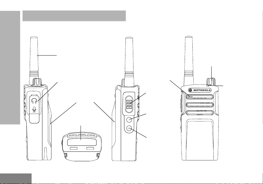
RADIO OVERVIEW
PARTS OF THE RADIO
RADIO OVERVIEW
English
10
Antenna
Audio Accessory
2 Pin Connector
Battery
Model Label
Microphone
PTT (Push-ToTalk) Button
SB1 - Monitor
Button
SB2 - Channel
Down Button
(Default)
On/Off/Volume
Knob
LED
Indicator
Page 15

On/Off/Volume Knob
Used to turn the radio ON or OFF and to adjust
the radio’s volume.
Accessory Connector
Used to connect compatible audio accessories.
Model Label
Indicates the model of the radio.
Microphone
Speak clearly into the microphone when
sending a message.
Antenna
On all RM Series radios, the antenna is nonremovable.
LED Indicator
Used to give battery status, power-up status,
radio call information and scan status.
Side Buttons
Push-to-Talk (PTT) Button
• Press and hold down this button to talk, release it
to listen.
Side Button 1 (SB1)
• The Side Button 1 is a general button that can be
configured by the Customer Programming
Software - CPS. The default setting of SB1 is
‘Monitor’.
Side Button 2 (SB2)
• The Side Button 2 is a general button that can be
configured by the CPS. The SB2 default setting is
‘scroll Down’ until the desired channel is selected.
The Lithium-Ion (Li-Ion) Battery
RM Series comes with a Li-Ion battery. For
more information, see “Battery Features” on
page 13.
RADIO OVERVIEW
11
English
Page 16
This User Guide covers multiple RM Series
models, and may detail some features your
radio does not have. The radio’s model is
shown on the bottom of the radio and provides
the following information:
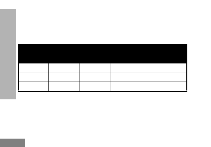
Table 1: RM Series Radio Specifications
RADIO OVERVIEW
English
Model
RMU2043 UHF 2 4 Non-removable
RMU2043 UHF 2 4 Non-removable
RMM2050 VHF-MURS 2 5 Non-removable
12
Frequency
Band
Transmit
Power
(Watts)
Number of
Channels
Antenna
Page 17

BATTERY FEATURES
About the Li-Ion Battery
The RM Series™ radio comes equipped with a
rechargeable Li-Ion battery. This battery should
be charged fully before initial use to ensure
optimum capacity and performance.
Battery life is determined by several factors.
Among the more critical are the regular
overcharge of batteries and the average depth
of discharge with each cycle. Typically, the
greater the overcharge and the deeper the
average discharge, the fewer cycles a battery
will last. For example, a battery which is
overcharged and discharged 100% several
times a day, lasts fewer cycles than a battery
that receives less of an overcharge and is
discharged to 50% per day. Further, a battery
which receives minimal overcharging and
averages only 25% discharge, lasts even
longer.
Motorola batteries are designed specifically to
be used with a Motorola charger and vice
versa. Charging in non-Motorola equipment
may lead to battery damage and void the
battery warranty. The battery should be at
about 77°F (25°C) (room temperature),
whenever possible. Charging a cold battery
(below 50° F [10°C]) may result in leakage of
electrolyte and ultimately in failure of the
battery. Charging a hot battery (above 95°F
[35°C]) results in reduced discharge capacity,
affecting the performance of the radio.
Motorola rapid-rate battery chargers contain a
temperature-sensing circuit to ensure that
batteries are charged within the temperature
limits stated above.
RADIO OVERVIEW
13
English
Page 18

Battery Recycling and Disposal
Li-Ion rechargeable batteries can be recycled.
However, recycling facilities may not be
available in all areas. Under various U.S. state
laws and the laws of several other countries,
batteries must be recycled and cannot be
disposed of in landfills or incinerators. Contact
your local waste management agency for
specific requirements and information in your
area. Motorola fully endorses and encourages
the recycling of Li-Ion batteries. In the U.S. and
Canada, Motorola participates in the
nationwide Rechargeable Battery Recycling
RADIO OVERVIEW
Corporation (RBRC) program for Li-Ion battery
collection and recycling.
Many retailers and dealers participate in this
program. For the location of the drop-off facility
closest to you, access RBRC's Internet web
site at:
www.rbrc.com
or call:
1-800-8-BATTERY
This internet site and telephone number also
provides other useful information concerning
recycling options for consumers, businesses
and governmental agencies.
English
14
Page 19
Installing the Lithium-Ion (Li-Ion) Battery
Removing the Lithium-Ion (Li-Ion) Battery
Attach
Press until click
Tabs
Slots
1. Turn OFF the radio.
2. With the Motorola logo side up on the battery
pack, fit the tabs at the bottom of the battery
into the slots at the bottom of the radio’s body.
3. Press the top part of the battery towards the
radio until a click is heard.
Note: To learn about the Li-Ion Battery Life
features, refer to “About the Li-Ion Battery”
on page 13
15
1. Turn OFF the radio.
2. Push down the battery latch and hold it while
removing the battery.
3. Pull the battery away from the radio.
Detach
Press Latch
RADIO OVERVIEW
English
Page 20
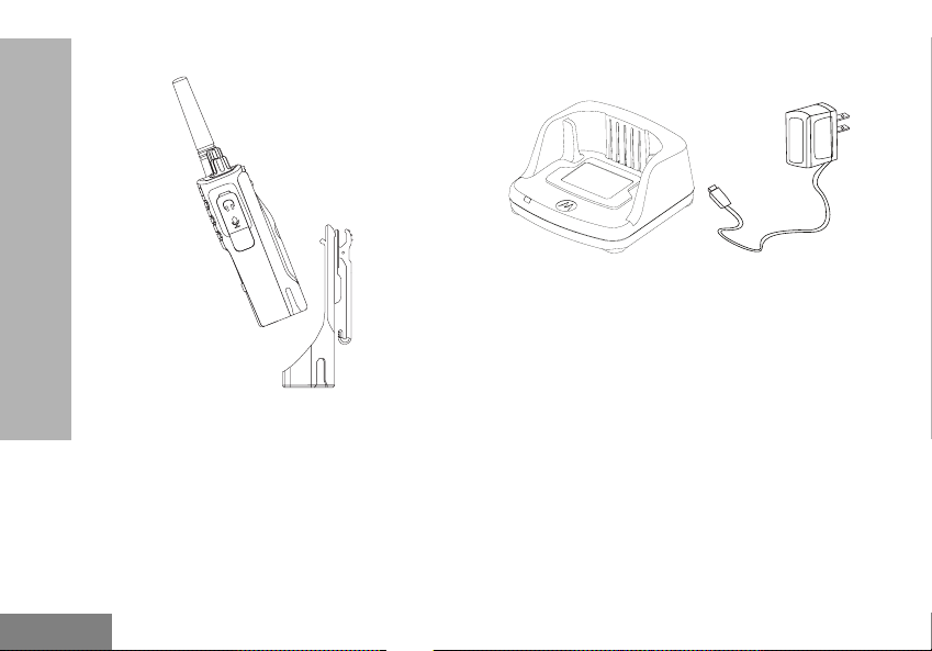
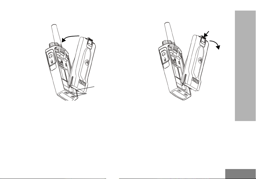
Holster
Power Supply, Adaptor and Drop-in Tray
Charger
RADIO OVERVIEW
English
1. Insert the radio into the base of the holster at an
angle. Press the radio against the back of the
holster until the hooks on the holster are
inserted in the top recesses of the battery.
2. To remove, using the top tab on the holster,
detach the hooks of the holster from the top
recesses of the battery. Slide the radio at an
angle and remove from the holster.
16
Drop-in Tray Charger
Power Supply
The radio is equipped with one Drop-in Tray
Charger and one Power Supply with Adaptor.
For more information, refer to “Chargers” on
page 67.
Page 21
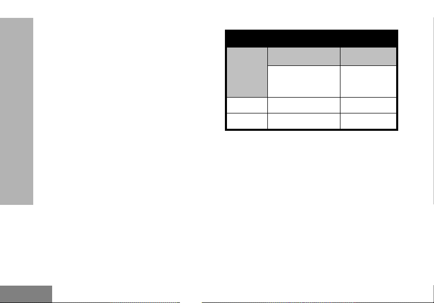
Battery Life Information
When the Battery Save feature is set to ON (enabled by default), the battery life lasts longer. The
following table summarizes battery life estimations:
Table 2: Li-Ion Battery Life with Tx Power 2 Watts
Battery Type Battery Save OFF Battery Save ON
Standard 12 Hours 15 Hours
High Capacity N/A N/A
Note: Battery life is estimated based on 5% transmit / 5% receive / 90% standby standard duty cycle.
RADIO OVERVIEW
17
English
Page 22
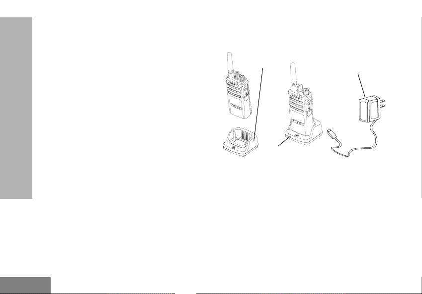
Charging the Battery
The RM Series radio offers two types of Power
Supplies:
• Standard Power Supply and,
• Rapid Power Supply
Note: The radio comes with a Standard Power
Supply.
To charge the battery (with the radio attached),
place it in a Motorola-approved Drop-in Tray
Single Unit Charger or Drop-in Tray Multi Unit
Charger.
RADIO OVERVIEW
Charging with the Drop-in Tray
Single Unit Charger (SUC)
Drop-in Tray
SUC Port
Drop-in Tray SUC
1. Place the Drop-in Tray Charger on a flat
surface.
2. Insert the connector of the Power Supply into
the charger port on the back of the Drop-in Tray
Charger.
3. Plug the AC Adaptor into a power outlet.
4. Insert the radio into the Drop-in Tray Single Unit
Charger with the radio facing the front, as
shown.
Power Supply
(Transformer)
English
18
Page 23
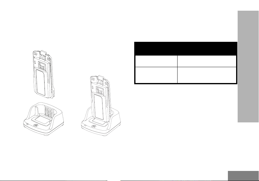
Note: When charging a battery attached to the
radio, turn the radio OFF to ensure a full
charge. See “Operational Safety Guidelines”
on page 9 for more information.
Charging A Stand-Alone Battery
above. Align the slots in the battery with the
alignment ribs in the Drop-in Tray Single Unit
Charger.
Table 3: Motorola Authorized Batteries
Part Number Description
PMNN4434_R Standard Li-Ion Battery
RADIO OVERVIEW
PMNN4453_R
High Capacity Li-Ion
Battery
To charge only the battery - at step 4 on
page 18, insert the battery into the tray, with the
inside surface of the battery facing the front of
the Drop-in Tray Single Unit Charger as shown
19
English
Page 24
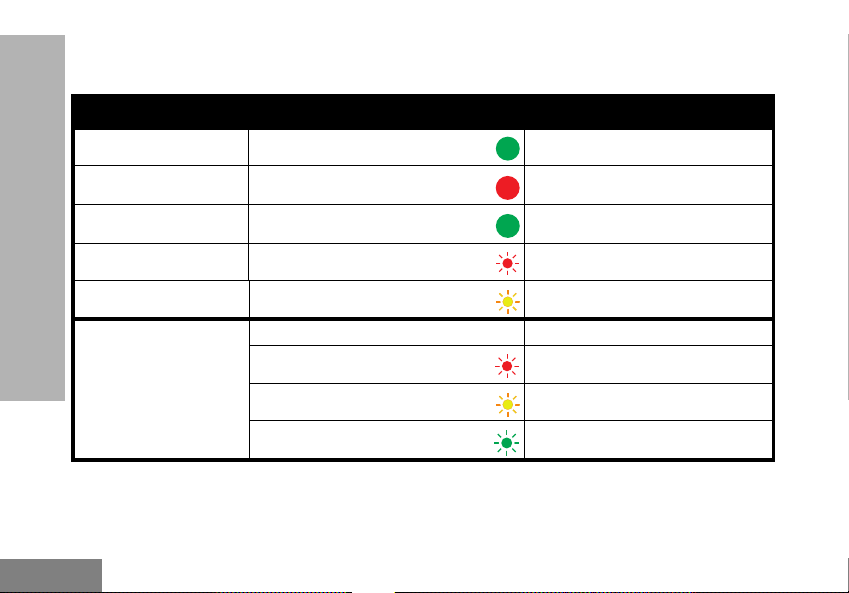
Drop-in Tray Charger LED Indicators
Table 4: Charger LED Indicator
Status LED Indicator Comments
Power On
Charging
Charging Complete
Battery Fault (*)
Waiting to Charge (**)
RADIO OVERVIEW
Battery Level Status
(*) Normally, re-positioning the battery pack will correct this issue.
(**) Battery temperature is too warm or too cold or wrong power voltage is being used.
Green for approximately 1 second
Steady Red
Steady Green
Red Fast Flash
Amber Slow Flash
N/A Battery empty
Flash Red 1 Time
Flash Amber 2 Times
Flash Green 3 Times
Battery low
Battery medium
Battery High
English
20
Page 25
If there is NO LED indication:
1. Check if the radio with battery, or the battery alone, is inserted correctly. (refer to step 4 of "Charging with the
Drop-in Tray Single Unit Charger (SUC)" on page 18)
2. Ensure that the power supply cable is securely plugged into the charger socket using an appropriate AC
outlet and there is power to the outlet.
3. Confirm that the battery being used with the radio is listed in Table 3.
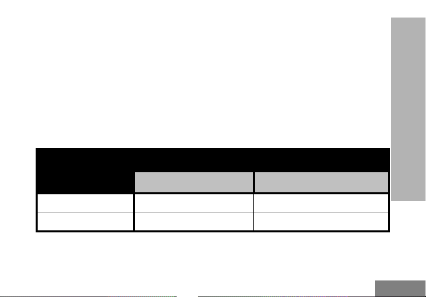
Estimated Charging Time
The following table provides the estimated charging time of the battery. For more information, see
“Battery” on page 66.
Table 5: Battery Estimated Charging Time
Estimated Charging Time
Charging Solutions
Standard Battery High Capacity Battery
Standard ≤ 4.5 Hours N/A
Rapid ≤ 2.5 Hours N/A
RADIO OVERVIEW
21
English
Page 26
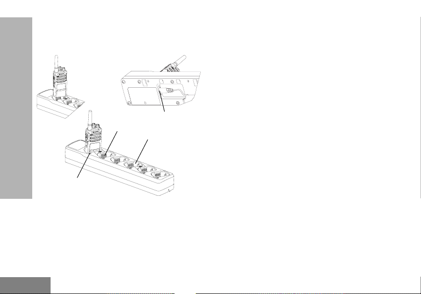
Charging a Radio and Battery using
a Multi Unit-Charger - MUC (Optional
Accessory)
Charger Power Receptacle
Charging Contacts
Charging Pocket
RADIO OVERVIEW
Charging Indicator
The Multi-Unit Charger (MUC) allows drop-in
charging of up to 6 radios or batteries. Batteries
can be charged with the radios or removed and
placed in the MUC separately. Each of the 6
charging pockets can hold a radio (with or
without the Holster) or battery, but not both.
1. Place the Multi-Unit Charger on a flat surface.
2. Insert the power cord plug into the MUC’s dual
pin connector at the bottom of the MUC.
3. Plug the power cord into an AC outlet.
4. Turn the radio OFF.
5. Insert the radio or battery into the charging
pocket with the radio or battery facing away
from the contacts.
Note:
• This Multi-Unit Charger clones up to 2 radios (2
Source radios and 2 Target radios). Refer to
“Cloning with a Multi Unit Charger (MUC)” on
page 43 for more information.
• More information on the Multi-Unit Charger’s
operation is available in the Instruction Sheets
provided with the MUC. For more information on
the parts and their part numbers, refer to Chapter
“Accessories” on page 66.
English
22
Page 27
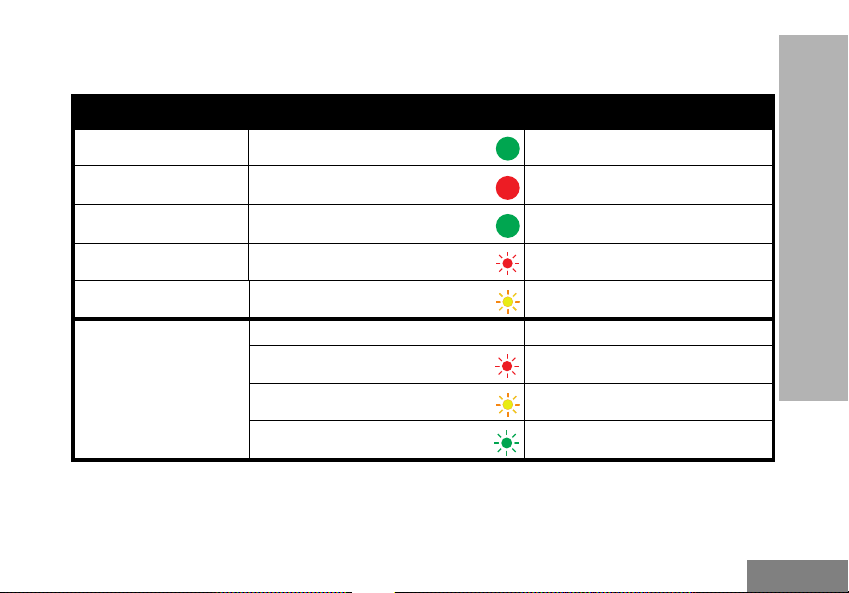
Multi-Unit Charger LED Indicators
Table 6: Charger LED Indicator
Status LED Indicator Comments
Power On
Charging
Charging Complete
Battery Fault (*)
Waiting to Charge (**)
Battery Level Status
(*) Normally, re-positioning the battery pack will correct this issue.
(**) Battery temperature is too warm or too cold or wrong power voltage is being used.
23
Green for approximately 1 second
Steady Red
Steady Green
Red Fast Flash
Amber Slow Flash
N/A Battery empty
Flash Red 1 Time
Flash Amber 2 Times
Flash Green 3 Times
Battery low
Battery medium
Battery High
RADIO OVERVIEW
English
Page 28

If there is NO LED indication:
1. Check if the radio with battery or the battery
alone, is inserted correctly (refer to step 5 of
"Charging a Radio and Battery using a Multi
Unit-Charger - MUC (Optional Accessory)" on
page 22).
2. Make sure the power cord is securely plugged
into the MUC and the appropriate AC outlet.
Make sure there is power to the AC outlet.
3. Confirm that the battery being used with the
radio is listed in Table 3.
RADIO OVERVIEW
English
24
Page 29

GETTING STARTED
For the following explanations, refer to “Parts
Of The Radio” on page 10.
TURNING RADIO ON/OFF
To turn ON the radio, rotate the On/Off/Volume
Knob clockwise. The radio plays one of the
following:
• Power up tone and channel number
announcement, or
• Battery level and channel number
announcements, or
• Silent (Audible tones disabled)
The LED blinks red briefly.
To turn the radio OFF, rotate the On/Off/Volume
Knob counterclockwise until you hear a ‘click’
and the radio LED Indicator turns OFF.
ADJUSTING VOLUME
Turn the On/Off/Volume Knob clockwise to
increase the volume, or counterclockwise to
decrease the volume.
Note: Do not hold the radio too close to the ear
when the volume is high or when adjusting
the volume
SELECTING A CHANNEL
To select a channel, press the SB2 button until
you reach the desired channel. An audible
voice indicates the selected channel.
Each channel has its own Frequency,
Interference Eliminator Code and Scan
Settings.
TALKING AND MONITORING
It is important to monitor for traffic before
transmitting to avoid ‘talking over’ someone
who is already transmitting
To monitor, long press and hold the SB1(*)
button to access channel traffic. If no activity is
present, you will hear ‘static’. To release, press
SB1 again. Once channel traffic has cleared,
proceed with your call by pressing the PTT
button. When transmitting, the LED Indicator
stays solid red.
GETTING STARTED
25
English
Page 30
Notes:
• To listen to all activity on a current channel, short
press the SB1 to set the CTCSS/DPL code to 0.
This feature is called ‘CTCSS/DPL Defeat
(Squelch set to SILENT)’.
• (*) This assumes SB1 is not being programmed
for a different mode.
RECEIVING A CALL
1. Select a channel by pressing the SB2 button
until you reach the desired channel. An audible
voice indicates the selected channel.
2. Make sure the PTT button is released and listen
GETTING STARTED
for voice activity.
3. The LED Indicator stays solid red when the
radio is receiving a call.
4. To respond, hold the radio vertically 1 to 2
inches (2.5 to 5cm) from mouth. Press the PTT
button to talk; release it to listen.
TALK RANGE
TALK RANGE
Industrial Multi-Level
Model
UHF 2W Up to 250,000 Sq. Ft. Up to 20 Floors
MURS 2W Up to 220,000 Sq. Ft. Up to 13 Floors
Inside steel/
concrete Industrial
buildings
Inside multi-
level buildings
English
26
Page 31

To establish a proper two-way communication,
the channel, frequency, and interference
eliminator codes must be the same on both
radios. This depends on the stored profile that
has been preprogrammed on the radio:
1. Channel: Current channel that the radio is
using, depending on radio model.
2. Frequency: The frequency the radio uses to
transmit/receive.
3. Interference Eliminator Code: These codes
help minimize interference by providing a
choice of code combinations.
4. Scramble Code: Codes that make the
transmissions sound garbled to anyone
listening who is not set to that specific code.
5. Bandwidth: Some frequencies have selectable
channel spacing, which must match other
radios for optimum audio quality (only available
for RMU2043).
For details on how to set up frequencies and
CTCSS/DPL codes in the channels, refer to
“Advanced Configuration Mode” on page 32.
GETTING STARTED
27
English
Page 32

RADIO LED INDICATORS
RADIO STATUS LED INDICATION
Channel Busy Solid Orange
Cloning Mode Double Orange Heartbeats
Cloning In Progress Solid Orange
Fatal Error at Power up
Low Battery Orange Heartbeat
Low Battery Shutdown Fast Orange Heartbeat
Monitor LED is OFF
Power-Up Solid Red for 2 seconds
GETTING STARTED
‘Idle’ Programming Mode /
Channel Mode
Scan Mode Fast Red Heartbeat
Transmit (Tx)/Receive (RX) Solid Red
Transmit in Low Power Select Solid Orange
VOX/iVOX Mode Double Red Heartbeats
One Green Blink, One Orange Blink, One Green Blink, then repeat for 4
seconds
Green Heartbeat
English
28
Page 33

HANDS-FREE USE/VOX
Accessory
Port/
Connector
VOX
Accessory
Motorola RM Series™ radios can operate
hands-free (VOX) when used with compatible
VOX accessories.
With Compatible VOX Accessories
The default factory setting for VOX sensitivity
level is OFF (level ‘0’). Before using VOX, set
VOX level to a level different from ‘0’ via the
Customer Programming Software (CPS). Then,
perform the following steps:
1. Turn the radio OFF.
2. Open accessory cover.
3. Insert the audio accessory’s plug firmly into
accessory port.
4. Turn radio ON. The LED Indicator will blink
double red
5. Lower radio volume BEFORE placing
accessory near ear.
6. To transmit, speak into accessory microphone
and to receive, stop talking.
7. VOX can be temporarily disabled by pressing
the PTT button or by removing the audio
accessory.
Note: To order accessories, refer to:
www.motorolasolutions.com/RMseries,
call 1 (800) 448-6686, or contact your
Motorola point of purchase
GETTING STARTED
29
English
Page 34

Setting VOX Sensitivity
The sensitivity of the radio's accessory or
microphone can be adjusted to suit different
operating environments. VOX sensitivity can
be programmed via the CPS.
Default value is OFF. If you want to use the
VOX feature, VOX level should be set at a
value different from OFF.
• 1 = High audio input levels trigger the Tx
• 2 = Medium sensitivity
• 3 = Low audio input levels trigger the Tx
Microphone Gain
GETTING STARTED
The sensitivity of the microphone can be
adjusted to fit different users or operating
environments.
This feature can be adjusted only through the
CPS. Microphone default setting is set to level
2 (medium gain).
Hands Free Without Accessories (iVOX)
• Enable iVOX by pressing the PTT button while
turning ON the radio.
• Pressing the PTT button can temporarily disable
the iVOX operation.
Note: There is a short delay between the time
when you start stalking and when the radio
transmits.
Power Up - Tone Mode
To enable/disable power up tone mode, press
SB1 and SB2 buttons simultaneously for 2-3
seconds while powering up the radio until you
hear a quick succession of beeps and an
audible voice announcement.
Reset to Factory Defaults
Reset to Factory Defaults will set back all radio
features to the original factory default settings.
To do so, press PTT, SB2 and SB1
simultaneously while turning ON the radio until
you hear a high tone chirp.
English
30
Page 35

Toggle Voice Prompt in User Mode
Short press the SB1 button while turning ON
the radio to enable/disable Voice Prompt in
User mode. This mode is set to ON by default.
GETTING STARTED
31
English
Page 36

PROGRAMMING
FEATURES
To easily program all the features in your radio,
it is recommended to use the Customer
Programming Software (CPS) and the
programming cable.
CPS software download is available for free at
www.motorolasolutions.com/RMseries.
ADVANCED CONFIGURATION MODE
Advanced Configuration is a configuration
mode that allows the customization of
additional features via the radio’s front panel.
For non-display model radios, the navigation is
PROGRAMMING FEATURES
guided by an audible voice prompt.
When the radio is set to Advanced
Configuration, you are able to read and modify
four features:
• Frequency Selection,
• Codes (CTCSS/DPL),
• Auto-Scan and,
• Active Channels
The Select Frequencies feature allows you to
choose frequencies from a pre-defined list.
The Interference Eliminator Code (CTCSS/
DPL) helps minimize interference by providing
you with a choice of code combinations that
filter out static, noise, and unwanted
messages.
The Auto-Scan feature allows you to set a
particular channel to automatically enable Scan
each time you switch to that channel.
The Active Channels feature allows you to
increase or decrease the amount of active
channels (In the range of maximum channels
allowed).
English
32
Page 37

Entering Advanced Configuration Mode
Note: Before configuring the features, make sure
your radio is set to the channel you wish to
program. You can do so before entering
Advanced Configuration Mode or at any
time during the Advanced Configuration
Mode by pressing the SB2 button until you
reach the desired channel.
To read or modify Frequencies, Codes, AutoScan and Active Channels, set the radio to
‘Advanced Configuration Mode’ by long
pressing both the PTT and the SB1 button
simultaneously for 3 to 5 seconds while turning
ON the radio until you hear an audible voice
saying “Programming Mode” and “Channel
Number”. The LED Indicator starts blinking a
green heartbeat.
Note: ‘Idle’ Programming Mode is the stage in the
Programming Mode where the radio waits
for the user to start the radio programming
cycle.
Once you are in the ‘Idle’ Programming Mode,
you will be able to hear the Frequencies,
Codes, Auto-Scan and Active Channels
settings by short pressing the PTT button to
navigate along the different programmable
features.
Entering Frequencies Values
RM Series radios have 89 frequencies for UHF
in USA and 2 frequencies for Canada UHF.
In ‘Idle’ Programming mode, the Channel
number becomes the first changeable value.
Move the Channel Up or Channel Down using
the SB1 and SB2 button. An audible voice
indicated the selected channel to configure.
Short pressing the PTT button allows you to
cycle through the other features available for
configuration. Use the SB1 and SB2 button to
change the values. An audible voice indicates
the value selected.
PROGRAMMING FEATURES
33
English
Page 38

Reading CTCSS / DPL Values
Cycle through the features available for
configuration by short pressing the PTT button
until you hear the current code. The radio
moves to the programming CTCSS/PL codes
mode.
Enter a new code value using the SB1 and SB2
buttons.
The RM Series radios have up to 219 codes
available. For more information, refer to
“Frequency and Code Charts” on page 53.
Reading Auto-Scan Values
After hearing the CTCSS/DPL codes, short
pressing the PTT button moves you to Auto-
PROGRAMMING FEATURES
Scan mode.
Auto-Scan has only two values:
• Enabled
• Disabled
Active Channels
While in Auto-Scan mode, short pressing the
PTT button shifts the radio to ‘Active Channels’
feature. Modify the amount of channels
available using the SB1 and SB2 buttons.
Saving Settings
Once you are satisfied with the settings, you
can either:
• short press the PTT button to continue
programming,
• long press the PTT button to save and return to
‘Idle’ Programming Mode, or
• long press the PTT button twice to exit ‘Idle’
Programming Mode and return to the normal
radio operation.
Note:
• To exit the programming mode without saving,
turn OFF the radio.
• If you ‘roll-over’ to the beginning of ‘Idle’
Programming Mode, you will hear “Channel
Number” . All changed values will be
automatically saved.
English
34
Page 39

Programming Mode FAQ
1. I got distracted while programming and forgot
which feature I was programming. What should
I do?
Return to ‘Idle’ Programming Mode and start
over. You will not be able to return to
Programming Mode (the radio does not provide
further way to let you know the specific stage
you are at in the Programming Mode).
Therefore you can:
• Long press the PTT button. The radio will return
to ‘Idle’ Programming Mode or,
• Turn OFF the radio and enter Programming
Mode again. (Refer to “Entering Advanced
Configuration Mode” on page 33 for more
information)
2. I am trying to program a frequency (or a code)
value but the radio would not do it. It rolled over
and took me back to value ‘0’.
The radio disallow you to program any value
that is not available in the frequencies and
codes pool. For example, if you try to program
code 220, the radio would not accept it as the
maximum value allowed is 219. Same goes for
the frequencies. Refer to the“Frequency and
Code Charts” on page 53 to make sure you are
programming a valid value.
3. I am trying to enter the Programming Mode but
the radio would not do it.
The radio may be locked using the CPS to
disallow Front Panel Programming. To reenable, use the CPS.
4. I programmed the wrong value when I was
programming. How can I erase or re-program
the value?
If you programmed the wrong value, you can
either:
• ‘Roll-over’ the radio. The radio ‘roll-over’ each
time it reaches the maximum value allowed. Keep
increasing (short press the SB1 button) or
decreasing (short press the SB2 button) until you
get the desired value or,
PROGRAMMING FEATURES
35
English
Page 40

• Turn OFF the radio and start over.
5. I just programmed the value I wanted. How do I
exit the Programming Mode?
You can either:
• long press the PTT button twice to exit if you’re in
the Programming Mode or,
• Long press the PTT button once if you are
already in the ‘Idle’ Programming mode.
6. I am done programming the features in this
channel. How do I program another channel?
Short press the PTT button several times until
you hear “Channel Number”. Switch channel
using the SB1 and SB2 buttons. If you wish to
save the changes, make sure you are in the
PROGRAMMING FEATURES
‘Idle’ Programming Mode before switching the
channel, otherwise you will lose the changes
made.
PROGRAMMING VALUES EXAMPLE
Example of Programming a Frequency
Assuming current frequency value is set to
Channel 1, with the UHF default frequency set
to ‘02’ (equivalent to 464.5500 MHz), and you
want to change it to Frequency Number = ‘13’
(which is mapped to 461.1375 MHz), follow this
sequence:
1. Enter Advanced Configuration Mode.
2. Short press the PTT button to enter Frequency
Mode. The radio audible voice announces that
the current value is ‘2’.
3. Press the SB1 button eleven times to increase
frequencies and you will hear frequency “One,
three” (13).
4. Long press the PTT button. LED Indicator
shows a green heartbeat to indicate ‘Idle’
Programming Mode.
5. Long press the PTT button again to exit
Programming Mode or turn OFF the radio.
English
36
Page 41

Example of Programming a Code
Assuming the current code value is set to
factory default ‘001’, and you want to change it
to CTCSS/DPL Code = 103. Follow the
sequence indicated below:
1. Enter Advanced Configuration Mode.
2. Short press the PTT button twice. The radio
audible voice announced “Code Number”
(Entering CTCSS/DPL Programming Selection
Mode).
3. Pressing and holding SB1 or SB2 button fast
forwards / rewinds the value at the nearest 10’s.
When released, the radio audible voice
announces the first, second and third digit in
full. Keep pressing the SB1 or SB2 button
several times until you hear “103”.
4. Long press the PTT button. LED Indicator
shows a green heartbeat to indicate ‘Idle’
Programming Mode.
5. Long press the PTT button again to exit
Programming Mode or turn OFF the radio.
Example of Programming Auto-Scan
Auto-Scan is the third available feature in the
Programming Mode and can be set to either
ON or OFF on a particular channel.
To set Auto-Scan to ON:
• Enter Advanced Configuration Mode and select
the desired channel.
• Short press the PTT button three times to enter
the Active Channels Programming Selection
Mode. The audible voice in the radio announces
“Auto-Scan” and the setting (Enabled or
Disabled).
• To change the setting, press SB1 or SB2.
• Long press the PTT button. LED Indicator shows
a green heartbeat to indicate ‘Idle’ Programming
Mode.
• Long press the PTT button again to exit
Programming Mode or turn OFF the radio.
PROGRAMMING FEATURES
37
English
Page 42

Example of Programming Active Channels
Active Channels is the last Programming
Mode. It allows you to modify the number of
active channels the radio is programmed to
support.
To set Active Channels:
• Enter Advanced Configuration Mode and select
the desired channel.
• Short press the PTT button four times to enter the
Active Channels Programming Selection Mode.
The audible voice in the radio announces “Active
Channels” and the current value.
• Short press the SB1 or SB2 button until you the
PROGRAMMING FEATURES
number of channels desired.
• Long press the PTT Button. LED Indicator shows
a green heartbeat to indicate ‘Idle’ Programming
Mode.
• Long press the PTT Button to exit Programming
Mode or turn OFF the radio.
OTHER PROGRAMMING FEATURES
Scan
Scan allows you to monitor other channels to
detect conversations. When the radio detects a
transmission, it stops scanning and goes to the
active channel. This allows you to listen and
talk to people in that channel without having to
change channel manually. If there are
transmissions on another channel, you will not
hear that activity once the radio has stopped
scanning. Once the activity on transmitting
channel stops, the radio waits for 5 seconds
before resuming scan again.
• To start scanning, press the SB1 or SB2 button
Note: Scan has to be programmed either to SB1
or SB2 button via CPS. SB2 is by default
Down Button for RMU2040/RMU2043/
RMM2050 models.
• To stop scanning, short press the SB1 or SB2
button (programmed for scan) again.
• By pressing the PTT button while the radio is
scanning, the radio will transmit on the channel
English
38
Page 43

which was previously selected before Scan is
activated. If no transmission occurs within 5
seconds, scanning resumes.
• If you want to scan a channel without the
Interference Eliminator Codes (CTCSS/DPL), set
the code settings for the channels to ‘0’ in the
CTCSS/DPL Programming Selection Mode.
Note: Whenever the radio is set to Scan, the LED
Indicator blinks a Red Heartbeat.
Editing Scan List
Scan List can be edited by using the CPS. For
more information refer to “Customer
Programming Software (CPS)” on page 40.
Nuisance Channel Delete
Nuisance Channel Delete allows you to
temporarily remove channels from the Scan
List. This feature is useful when irrelevant
conversations on a ‘nuisance’ channel ties up
the radio’s scanning feature.
To delete a channel from the Scan List:
• Start Scan mode by short pressing the SB1 or
SB2 (programmed for scan) button.
• Wait until the radio stops at the channel you wish
to eliminate. Long press the SB2 button to delete
it. You cannot delete the channel with scan
enabled (home channel).
• The channel will not be scanned again until you
exit the Scan mode by short pressing the SB1 or
SB2 (programmed for scan) button again or by
turning OFF the radio and back ON.
PROGRAMMING FEATURES
39
English
Page 44

CUSTOMER PROGRAMMING SOFTWARE
(CPS)
Radio to be
programmed
USB Ports
CPS Programming Cable
Drop-In Tray Charger Tray
Figure 1: Setting up the radio to the CPS
PROGRAMMING FEATURES
The easiest way to program or change features
in your radio is by using the Customer
Programming Software (CPS) and the CPS
Programming Cable(*). CPS Software is
available for free as web based downloadable
software at:
www.motorolasolutions.com/RMseries
To program, connect the RM Series radio via
the Drop-in Charger Tray and CPS
Programming Cable as shown in Figure 1 on
page 40.
CPS allows you to program frequencies, PL/
DPL Codes as well as other features such as:
Bandwidth Select, Time-out Timer, Power
Select, Scan List, Call Tones, Scramble,
Reverse Burst, etc. CPS is a very useful tool as
it can also lock the Front-Panel Radio
Programming or restrict any specific radio
feature to be changed (to avoid accidentally
erasing the preset radio values). It also
provides security by giving the option to set up
a password for profile radio’s management. For
more information, refer to Features Summary
Chart Section at the end of the User Guide.
Note: (*) CPS Programming Cable P/N#
HKKN4027_ is an accessory sold
separately. Please contact your Motorola
point of purchase for more information.
English
40
Page 45

Bandwidth Select (Only for Canada models)
All US models are compliant with the
narrowbandwidth FCC regulation.
Default setting for Bandwidth Select depends
on the specific frequency and channel. Some
frequencies have selectable channel spacing,
which must match with other radios for
optimum audio quality.
For details, refer to Frequency and Code
Charts section.
Time-Out Timer
When pressing the PTT button, transmissions
can be terminated by setting up a 'time-out’
timer.
Power Select
Power Select allows you to select between
high and low transmission power per frequency
in each channel. The power levels for RM
Series 2W toggle between 1W and 2W.
Note: Some frequencies may have FCC transmit
power restrictions that do not allow them to
be set at a higher power level. For details
see the Frequencies and Code Chart
Section.
Call Tones
Call Tones feature allows you to transmit an
audible tone to other radios on the same
channel to alert them that you are about to talk
or to alert them without speaking.
To use this feature, the Call Tones must be
programmed to either SB1 or SB2 and 1 of the
3 pre-recorded tones is selected.
Scramble
The Scramble feature makes transmissions
sound garbled to anyone listening without the
same code. Scramble default value is OFF. To
change the scramble code during radio’s
normal operation, the Scramble feature must
be programmed to either SB1 or SB2.
PROGRAMMING FEATURES
41
English
Page 46

Reverse Burst
Reverse Burst eliminates unwanted noise
(squelch tail) during loss of carrier detection.
You can select values of either 180 or 240 to be
compatible with other radios. The default value
is 180.
Notes:
• The features described in previous pages are just
some of the features CPS has. CPS offers more
capabilities. For more information refer to the
HELP file in the CPS.
PROGRAMMING FEATURES
CLONING RADIOS
You can clone RM Series radio profiles from
one Source radio to a Target radio by using any
one of these 3 methods:
• Using a Multi Unit Charger (MUC- optional
accessory),
• Using two Single Unit Chargers (SUC) and a
Radio-to-Radio cloning cable (optional
accessory),
• the CPS (free software download)
English
42
Page 47

Cloning with a Multi Unit Charger (MUC)
Pocket 1
“CLONE” symbol
Pocket 2 “CLONE” symbol Pocket 5
Pocket 4
To clone radios using the MUC, there must be
at least two radios:
• a Source radio (radio which profiles will be cloned
or copied from) and
• a Target radio (the radio which profile will be
cloned from the source radio.)
The Source radio has to be in Pocket 1 or 4
while the Target radio has to be in Pocket 2 or
5, matching in the MUCs pockets by pairs as
follows:
• 1 and 2 or,
• 4 and 5.
When cloning, the MUC does not need to be
plugged into a power source, but ALL radios
require charged batteries.
1. Turn ON the Target radio and place it into one of
the MUC Target Pockets
2. Power the Source radio following the sequence
below:
• Press the PTT button and SB2
simultaneously while turning the radio
ON.
• Wait for 3 seconds before releasing the
buttons until the audible tone “Cloning” is
heard.
3. Place the Source radio in the source pocket that
pairs with the target pocket you chose in step 1.
Press and release the SB1 button.
4. After cloning is completed, the Source radio will
announce either “successful” (cloning is
successful) or “fail” (cloning has failed). If the
Source radio is a display model, it will either
PROGRAMMING FEATURES
43
English
Page 48

show ‘Pass’ or ‘Fail’ on the display (a voice
announcement will be played within 5 seconds).
5. Once you have completed the cloning process,
turn the radios OFF and ON to exit the ‘cloning’
mode.
Further details on how to clone radios are
explained in the Instructions Sheet provided
with the MUC.
When ordering the MUC, refer to P/N#
PMLN6384_.
Notes:
• If cloning fails, refer to “What To Do If Cloning
Fails” on page 46.
• Paired Target radios and Source radios must be
PROGRAMMING FEATURES
of the same band type in order for the cloning to
run successfully.
• MUC pockets numbers should be read from left to
right with the Motorola logo facing front.
CPS and Cloning Cables (Optional
Accessory)
• Both CPS and Cloning Cables are made to work
either with RM Series radios or RDX Series
radios. Cloning cable supports a mix of RM and
RDX series radios.
• CPS cable programs RM series radios. Make
sure the cable switch is in “Flash” position. To
program a RDX radio with the CPS cable, make
sure the cable switch is in “CPS” position and the
USB converter provided in the CPS cable kit is
attached to the cable.
• Cloning cable allows you to clone:
–RM Series radios. Make sure the switch is in
“Cloning” or “Legacy” position.
–RDX Series radios. Make sure the switch is in
“Legacy” position with one USB converter on
each end of the cloning cable.
–RM Series and RDX Series radios. Make sure
the switch is in “Legacy” position and use a
USB converter to the RDX Single-Unit Charger.
The Cloning Cable Kit provides 1 USB
converter.
English
44
Page 49

CPS Cable Cloning Radio using the Radio to Radio
(R2R) Cloning Cable (Optional Accessory)
Cloning Cable
USB Converter
Cloning Cable
Unique Micro to Mini Converter
Operating Instructions
1. Before starting the cloning process, make sure
you have:
• A fully charged battery on each of the radios.
• Two Single-Unit Chargers (SUC), or 2 SUC for
cloning RM Series radios, or 1 SUC for RM
Series radio and 1 SUC for RDX Series radio.
• Turn OFF the radios and,
PROGRAMMING FEATURES
45
English
Page 50

2. Unplug any cables (power supply or USB
cables) from the SUCs.
3. Plug one side of the cloning cable mini USB
connector to the first SUC and the other end to
the second SUC.
Note: During the cloning process, no power is
being applied to the SUC. The batteries will
not be charged. Only data communication is
being established between the two radios.
4. Turn ON the Target Radio and place it into one
of the SUCs.
5. For the Source Radio, power ON the radio with
the following sequence:
• Press the PTT button and the SB2 button
PROGRAMMING FEATURES
simultaneously while turning the radio ON.
• Place the Source Radio in its SUC. Press and
release the SB1 button.
6. Wait 3 seconds before releasing the buttons
and you hear a distinctive audible tone saying
the word “Cloning”.
7. When the cloning is completed, the Source
Radio audible voice will announce either
“successful” (cloning is successful) or “fail”
(cloning process has failed). If the Source
Radio is a display model radio, it will either
show ‘Pass’ or ‘Fail’ on the display (a tone will
be heard within 5 seconds).
8. Once the cloning process is completed, turn the
Radios OFF and ON or, long press the PTT
button to exit the ‘cloning’ mode.
What To Do If Cloning Fails
The radio audible voice will announce “Fail”
indicating that the cloning process has failed. In
the event that the cloning fails, perform each of
the following steps before attempting to start
cloning process again:
1. Ensure that the batteries on both radios are fully
charged.
2. Check the cloning cable connection on both
SUCs.
3. Ensure that the battery is engaged properly on
the radio.
English
46
Page 51

4. Ensure that there is no debris in the charging
tray or on the radio contacts.
5. Ensure that the Target radio is turned ON.
6. Ensure that the Source radio is in cloning mode.
7. Ensure that the two radios are both from the
same frequency band, same region and have
the same transmission power.
Note: This cloning cable is designed to operate
only with compatible Motorola SUC
RLN6175 and PMLN6394.
When ordering Cloning Cable, please refer to
P/N# HKKN4028_. For more information about
the accessories, refer to “Accessories” on
page 66.
Cloning using the Customer Programming
Software (CPS)
When cloning using this method, you need the
CPS software, a Drop-In Tray Charger and the
CPS Programming Cable.
To order the CPS Programming Cable, please
refer to HKKN4028A.
Information on how to clone using the CPS is
available either in:
• the CPS Help File --> Content and Index -->
Cloning Radios, or
• in the CPS Programming Cable Accessory
Leaflet.
Radio to be
programmed
USB Ports
CPS Programming Cable
Drop-in Tray Charger
PROGRAMMING FEATURES
47
English
Page 52

TROUBLESHOOTING
Symptom Try This...
No Power
Hearing other noises or
conversation on a channel
TROUBLESHOOTING
Message Scrambled
Recharge or replace the Li-Ion battery.
Extreme operating temperatures may affect battery life.
Refer to “About the Li-Ion Battery” on page 13
Confirm Interference Eliminator Code is set.
Frequency or Interference Eliminator Code may be in use.
Change settings: either change frequencies or codes on all radios.
Make sure radio is at the right frequency and code when transmitting.
Refer to “Talking and Monitoring” on page 25
Scramble Code might be ON, and/or setting does not match the other radios'
settings.
English
Audio quality not good enough
48
Radio settings might not be matching up correctly. Double check frequencies,
codes and bandwidths to make sure they are identical in all radios
Page 53

Symptom Try This...
Steel and/or concrete structures, heavy foliage, buildings or vehicles decrease
range. Check for clear line of sight to improve transmission.
Wearing radio close to body such as in a pocket or on a belt decreases range.
Limited talk range
Message not transmitted or
received
Change location of radio. To increase range and coverage, you can reduce
obstructions or increase power. UHF radios provides greater coverage in
industrial and commercial buildings. Increasing power provides greater signal
range and increased penetration through obstructions.
Refer to “Talking and Monitoring” on page 25
Make sure the PTT button is completely pressed when transmitting.
Confirm that the radios have the same Channel, Frequency, Interference
Eliminator Code and Scramble Code settings. Refer to “Talking and Monitoring”
on page 25 for further information.
Recharge, replace and/or reposition batteries. Refer to “About the Li-Ion
Battery” on page 13.
Obstructions and operating indoors, or in vehicles, may interfere. Change
location. Refer to “Talking and Monitoring” on page 25.
Verify that the radio is not in Scan. Refer to “Scan” on page 38 and “Nuisance
Channel Delete” on page 39.
TROUBLESHOOTING
49
English
Page 54

Symptom Try This...
Heavy static or interference
Low batteries
Drop-in Charger LED light
does not blink
TROUBLESHOOTING
Low battery indicator is
blinking although new
batteries are inserted
Radios are too close; they must be at least five feet apart.
Radios are too far apart or obstacles are interfering with transmission.
Refer to “Talking and Monitoring” on page 25.
Recharge or replace Li-Ion battery.
Extreme operating temperatures affect battery life.
Refer to “About the Li-Ion Battery” on page 13.
Check that the radio/battery is properly inserted and check the battery/charger
contacts to ensure that they are clean and charging pin is inserted correctly.
Refer to “Charging the Battery” on page 18, “Drop-in Tray Charger LED
Indicators” on page 20 and “Installing the Lithium-Ion (Li-Ion) Battery” on
page 15.
Refer to “Installing the Lithium-Ion (Li-Ion) Battery” on page 15, and “About the
Li-Ion Battery” on page 13.
English
50
Page 55

Symptom Try This...
VOX feature might be set to OFF.
Cannot activate VOX
Battery does not charge
although it has been placed in
the drop-in charger for a while
Note: Whenever a feature in the radio seems to not correspond to the default or preprogrammed values, check
to see if the radio has been programmed using the CPS with a customized profile.
Use the CPS to ensure that the VOX Sensitivity level is not set to ‘0’.
Accessory not working or not compatible.
Refer to “Hands-Free Use/VOX” on page 29.
Check drop-in tray charger is properly connected and correspond to a
compatible power supply.
Refer to “Charging with the Drop-in Tray Single Unit Charger (SUC)” on
page 18 and “Charging A Stand-Alone Battery” on page 19.
Check the charger’s LEDs indicators to see if the battery has a problem. Refer
to “Drop-in Tray Charger LED Indicators” on page 20.
TROUBLESHOOTING
51
English
Page 56

USE AND CARE
Use a soft damp cloth to
USE AND CARE
If the radio is submerged in water...
English
52
clean the exterior
Turn radio OFF and
remove batteries
Do not immerse in water Do not use alcohol or
cleaning solutions
Dry with soft cloth Do not use radio until
completely dry
Page 57

FREQUENCY AND CODE CHARTS
RMU2043 – UHF DEFAULT FREQUENCIES CHART
RM UHF 4CH Radios Default Frequencies – RMU2043
Channel Frequency #
1 1 458.6625 1 67.0 Hz 12.5 kHz
2 2 469.2625 1 67.0 Hz 12.5 kHz
Frequency
(MHz)
Code # Code Bandwidth
FREQUENCY AND CODE
CHARTS
53
English
Page 58

RMU2040 – UHF DEFAULT FREQUENCIES CHART
RM UHF 4CH Radios Default Frequencies – RMU2040
Channel Frequency #
1 2 464.5500 1 67.0 Hz 12.5 kHz
2 8 467.9250 1 67.0 Hz 12.5 kHz
Frequency
(MHz)
CHARTS
FREQUENCY AND CODE
Code # Code Bandwidth
English
54
Page 59

RMM2050 – VHF-MURS DEFAULT FREQUENCIES CHART
RM VHF-MURS 5CH Radios Default Frequencies – RMM2050
Channel Frequency #
1 1 154.5700 1 67.0 Hz 20.0 kHz
2 2 154.6000 1 67.0 Hz 20.0 kHz
3 3 151.8200 1 67.0 Hz 11.25 kHz
4 4 151.8800 1 67.0 Hz 11.25 kHz
5 5 151.9400 1 67.0 Hz 11.25 kHz
Frequency
(MHz)
Code # Code Bandwidth
Especial Features Requirements
• Non repeater capable.
• Non-bandwidth selectable (the FCC defines the specific bandwidth requirement for each of the MURS
frequencies).
• No power select feature.
• No direct frequency input (does not support programming of part 90 frequencies).
• No standard frequency pull down MENU (should only have the 5 MURS frequencies).
Cloning should follow standard BL Solomons platform rules; no cloning between radios of different
channel distribution (ie. CP110 and RDX) or models from different regions.
55
FREQUENCY AND CODE
CHARTS
English
Page 60

CTCSS AND PL/DPL CODES
CTCSS Hz CTCSS Hz CTCSS Hz
1 67.0 14 107.2 27 167.9
2 71.9 15 11 0.9 28 173.8
3 74.4 16 114.8 29 179.9
4 77.0 17 11 8.8 30 186.2
5 79.7 18 123 31 192.8
CHARTS
FREQUENCY AND CODE
6 82.5 19 127.3 32 203.5
7 85.4 20 131.8 33 210.7
8 88.5 21 136.5 34 218.1
9 91.5 22 141.3 35 225.7
10 94.8 23 146.2 36 233.6
11 97.4 24 151.4 37 241.8
12 100.0 25 156.7 38 250.3
13 103.5 26 162.2 122 (*) 69.3
Note: (*) New CTCSS code.
CTCSS Codes
English
56
Page 61

PL/DPL Codes
DPL Code DPL Code DPL Code
39 23 55 116 71 243
40 25 56 125 72 244
41 26 57 131 73 245
42 31 58 132 74 251
43 32 59 134 75 261
44 43 60 143 76 263
45 47 61 152 77 265
46 51 62 155 78 271
47 54 63 156 79 306
48 65 64 162 80 311
49 71 65 165 81 315
50 72 66 172 82 331
51 73 67 174 83 343
52 74 68 205 84 346
53 114 69 223 85 351
54 115 70 226 86 364
FREQUENCY AND CODE
CHARTS
57
English
Page 62

PL/DPL Codes (Continued)
DPL Code DPL Code DPL Code
87 365 104 565 121 754
88 371 105 606 123 645
89 411
90 412 107 624 125 Customized PL
91 413 108 627 126 Customized PL
92 423 109 631 127 Customized PL
CHARTS
FREQUENCY AND CODE
93 431 110 632 128 Customized PL
94 432 111 654 129 Customized PL
95 445 112 662 130 Inverted DPL 39
96 464 113 664 131 Inverted DPL 40
97 465 114 703 132 Inverted DPL 41
98 466 115 712 133 Inverted DPL 42
99 503 116 723 134 Inverted DPL 43
100 506 117 731 135 Inverted DPL 44
101 516 118 732 136 Inverted DPL 45
102 532 119 734 137 Inverted DPL 46
103 546 120 743 138 Inverted DPL 47
106 612 124 Customized PL
English
58
Page 63

PL/DPL Codes (Continued)
DPL Code DPL Code DPL Code
139 Inverted DPL 48 156 Inverted DPL 65 173 Inverted DPL 82
140 Inverted DPL 49 157 Inverted DPL 66 174 Inverted DPL 83
141 Inverted DPL 50 158 Inverted DPL 67 175 Inverted DPL 84
142 Inverted DPL 51 159 Inverted DPL 68 176 Inverted DPL 85
143 Inverted DPL 52 160 Inverted DPL 69 177 Inverted DPL 86
144 Inverted DPL 53 161 Inverted DPL 70 178 Inverted DPL 87
145 Inverted DPL 54 162 Inverted DPL 71 179 Inverted DPL 88
146 Inverted DPL 55 163 Inverted DPL 72 180 Inverted DPL 89
147 Inverted DPL 56 164 Inverted DPL 73 181 Inverted DPL 90
148 Inverted DPL 57 165 Inverted DPL 74 182 Inverted DPL 91
149 Inverted DPL 58 166 Inverted DPL 75 183 Inverted DPL 92
150 Inverted DPL 59 167 Inverted DPL 76 184 Inverted DPL 93
151 Inverted DPL 60 168 Inverted DPL 77 185 Inverted DPL 94
152 Inverted DPL 61 169 Inverted DPL 78 186 Inverted DPL 95
153 Inverted DPL 62 170 Inverted DPL 79 187 Inverted DPL 96
154 Inverted DPL 63 171 Inverted DPL 80 188 Inverted DPL 97
155 Inverted DPL 64 172 Inverted DPL 81 189 Inverted DPL 98
FREQUENCY AND CODE
CHARTS
59
English
Page 64

PL/DPL Codes (Continued)
DPL Code DPL Code DPL Code
190 Inverted DPL 99 200 Inverted DPL 109 210 Inverted DPL 119
191 Inverted DPL 100 201 Inverted DPL 110 211 Inverted DPL 120
192 Inverted DPL 101 202 Inverted DPL 111 212 Inverted DPL 121
193 Inverted DPL 102 203 Inverted DPL 112 213 Inverted DPL 123
194 Inverted DPL 103 204 Inverted DPL 113 214 Customized DPL
195 Inverted DPL 104 205 Inverted DPL 114 215 Customized DPL
CHARTS
196 Inverted DPL 105 206 Inverted DPL 115 216 Customized DPL
197 Inverted DPL 106 207 Inverted DPL 116 217 Customized DPL
198 Inverted DPL 107 208 Inverted DPL 117 218 Customized DPL
199 Inverted DPL 108 209 Inverted DPL 118 219 Customized DPL
FREQUENCY AND CODE
English
60
Page 65

Notes
FREQUENCY AND CODE
CHARTS
61
English
Page 66

MOTOROLA LIMITED
WARRANTY FOR THE
UNITED STATES AND
CANADA
What Does this Warranty Cover?
Subject to the exclusions contained below,
Motorola, Inc. warrants its telephones, pagers, and
consumer and business two-way radios (excluding
commercial, government or industrial radios) that
operate via Family Radio Service or General
Mobile Radio Service, Motorola-branded or
certified accessories sold for use with these
Products (“Accessories”) and Motorola software
MOTOROLA LIMITED
contained on CD-ROMs or other tangible media
and sold for use with these Products (“Software”)
to be free from defects in materials and
WARRANTY FOR THE UNITED
workmanship under normal consumer usage for
the period(s) outlined below.
This limited warranty is a consumer's exclusive
remedy, and applies as follows to new Motorola
Products, Accessories and Software purchased by
consumers in the United States, which are
accompanied by this written warranty.
Products and Accessories
Products Covered Length of Coverage
Products and
Accessories as defined
above, unless otherwise
provided for below.
Decorative
Accessories and
Cases.
Decorative covers,
bezels, PhoneWrap™
covers and cases.
Business Two-way
Radio Accessories
Products and
Accessories that are
Repaired or Replaced.
One (1) year from the date
of purchase by the first
consumer purchaser of the
product unless otherwise
provided for below.
Limited lifetime warranty
for the lifetime of ownership
by the first consumer
purchaser of the product.
One (1) year from the date
of purchase by the first
consumer purchaser of the
product.
The balance of the original
warranty or for ninety (90)
days from the date returned
to the consumer, whichever
is longer.
English
62
Page 67

Exclusions
Normal Wear and Tear. Periodic maintenance,
repair and replacement of parts due to normal
wear and tear are excluded from coverage.
Batteries. Only batteries whose fully charged
capacity falls below 80% of their rated capacity
and batteries that leak are covered by this limited
warranty.
Abuse & Misuse. Defects or damage that result
from: (a) improper operation, storage, misuse or
abuse, accident or neglect, such as physical
damage (cracks, scratches, etc.) to the surface of
the product resulting from misuse; (b) contact with
liquid, water, rain, extreme humidity or heavy
perspiration, sand, dirt or the like, extreme heat, or
food; (c) use of the Products or Accessories for
commercial purposes or subjecting the Product or
Accessory to abnormal usage or conditions; or (d)
other acts which are not the fault of Motorola, are
excluded from coverage.
Use of Non-Motorola Products and
Accessories. Defects or damage that result from
the use of Non-Motorola branded or certified
Products, Accessories, Software or other
peripheral equipment are excluded from coverage.
Unauthorized Service or Modification. Defects
or damages resulting from service, testing,
adjustment, installation, maintenance, alteration,
or modification in any way by someone other than
Motorola, or its authorized service centers, are
excluded from coverage.
Altered Products. Products or Accessories with
(a) serial numbers or date tags that have been
removed, altered or obliterated; (b) broken seals
or that show evidence of tampering; (c)
mismatched board serial numbers; or (d)
nonconforming or non-Motorola housings, or
parts, are excluded form coverage.
WARRANTY FOR THE UNITED
MOTOROLA LIMITED
63
English
Page 68

MOTOROLA LIMITED
English
Communication Services. Defects, damages, or
the failure of Products, Accessories or Software
due to any communication service or signal you
may subscribe to or use with the Products
Accessories or Software is excluded from
coverage.
Software
Products Covered Length of Coverage
Software. Applies only
to physical defects in
the media that
embodies the copy of
the software (e.g. CDROM, or floppy disk).
Ninety (90) days from the
date of purchase.
Exclusions
WARRANTY FOR THE UNITED
Software Embodied in Physical Media. No
warranty is made that the software will meet your
requirements or will work in combination with any
hardware or software applications provided by
third parties, that the operation of the software
products will be uninterrupted or error free, or that
all defects in the software products will be
corrected.
64
Software NOT Embodied in Physical Media.
Software that is not embodied in physical media
(e.g. software that is downloaded from the
internet), is provided “as is” and without warranty.
WHO IS COVERED?
This warranty extends only to the first consumer
purchaser, and is not transferable.
HOW TO OBTAIN WARRANTY SERVICE OR
OTHER INFORMATION?
Contact your Motorola point of purchase.
SOFTWARE COPYRIGHT NOTICE
The Motorola products described in this manual
may include copyrighted Motorola and third party
software stored in semiconductor memories or
other media. Laws in the United States and other
countries preserve for Motorola and third party
software providers certain exclusive rights for
copyrighted software, such as the exclusive rights
to distribute or reproduce the copyrighted
software. Accordingly, any copyrighted software
contained in the Motorola products may not be
modified, reverse-engineered, distributed, or
reproduced in any manner to the extent allowed by
law.
Page 69

Furthermore, the purchase of the Motorola
products shall not be deemed to grant either
directly or by implication, estoppel, or otherwise,
any license under the copyrights, patents, or
patent applications of Motorola or any third party
software provider, except for the normal, nonexclusive, royalty-free license to use that arises by
operation of law in the sale of a product.
PATENT NOTICE
This product is covered by one or more of the
following United States patents.
5896277 5894292 5864752 5699006 5742484
D408396 D399821 D387758 D389158 5894592
5893027 5789098 5734975 5861850 D395882
D383745 D389827 D389139 5929825 5926514
5953640 6071640 D413022 D416252 D416893
D433001
EXPORT LAW ASSURANCES
This product is controlled under the export
regulations of the United States of America. The
Governments of the United States of America may
restrict the exportation or re-exportation of this
product to certain destinations. For further
information contact the U.S. Department of
Commerce.
WARRANTY FOR THE UNITED
MOTOROLA LIMITED
65
English
Page 70

ACCESSORIES
AUDIO ACCESSORIES
Part No. Description
53815 Headset w/Boom Mic BR
HMN9026_R Remote Speaker Mic BR
HKLN4477_ Surveillance Earpiece BR
BATTERY
Part No. Description
PMNN4434_R Standard Li-Ion Battery
PMNN4453_R High Capacity Li-Ion Battery
SOFTWARE APPLICATIONS
Part No. Description
ACCESSORIES
English
53865 Headset w/Swivel Boom Mic
53866 Earbud w/Clip PTT Mic BR
56517 Earpiece w/Inline Mic
RLN6423_ Swivel Earpiece BR
66
82012694001
Customer Programming
Software (CPS)
CABLES
Part No. Description
HKKN4028_ Radio to Radio Cloning Cable
HKKN4027_ CPS Programming Cable
Page 71

CHARGERS
Part No. Description
PMLN6384_
PMLN6394_ Standard Drop-In Tray Charger
Multi-Unit Charger (MUC) Kit North America
CARRY ACCESSORIES
Part No. Description
HKLN4510_ Swivel Holster
67
ACCESSORIES
English
Page 72

Notes
ACCESSORIES
English
68
Page 73

TABLE DES MATIÈRES
Table des matières . . . . . . . . . . . . . . . . . . . .1
Produit Sécurité. . . . . . . . . . . . . . . . . . . . . . .4
Introduction . . . . . . . . . . . . . . . . . . . . . . . . . .6
Contenu de l’emballage. . . . . . . . . . . . . . . . . .6
Informations sur les licenses
de la FCC . . . . . . . . . . . . . . . . . . . . . . . . . . . .8
Informations sur l’interférence. . . . . . . . . . . . .8
Informations sur l’accord de licence
pour le Canada . . . . . . . . . . . . . . . . . . . . . .10
Informations générales . . . . . . . . . . . . . . . . .10
La demande de license . . . . . . . . . . . . . . . . .10
Consignes de sécurité pour les
batteries et les chargeurs. . . . . . . . . . . . . . .8
Règles générales de sécurité en
fonctionnement . . . . . . . . . . . . . . . . . . . . . . .9
Vue générale de la radio. . . . . . . . . . . . . . .10
Éléments de la Radio . . . . . . . . . . . . . . . . . .10
Bouton Marche/Arrêt/Volume . . . . . . . . .11
Connecteur d’accessoire . . . . . . . . . . . .11
Étiquette modèle. . . . . . . . . . . . . . . . . . .11
Microphone . . . . . . . . . . . . . . . . . . . . . . .11
Antenne . . . . . . . . . . . . . . . . . . . . . . . . . 11
Témoin lumineux . . . . . . . . . . . . . . . . . . 11
Boutons latéraux . . . . . . . . . . . . . . . . . . 11
La batterie au Lithium-Ion (Li-Ion) . . . . . 11
Caractéristiques de la batterie . . . . . . . . . . . 13
À propos de la batterie Li-Ion. . . . . . . . . 13
Recyclage et traitement de la batterie . . 14
Installation de la batterie au
Lithium-Ion (Li-Ion). . . . . . . . . . . . . . . 15
Retirer la batterie au Lithium-Ion
(Li-Ion) . . . . . . . . . . . . . . . . . . . . . . . . 15
Étui. . . . . . . . . . . . . . . . . . . . . . . . . . . . . 16
Alimentation Életrique , Adaptateur
et Bloc Chargeur . . . . . . . . . . . . . . . . 16
Informations sur l’autonomie de
la batterie . . . . . . . . . . . . . . . . . . . . . . 17
Recharge de la batterie . . . . . . . . . . . . . 18
Témoins lumineux du bloc chargeur . . . 20
Estimation du temps de charge . . . . . . . 21
Témoin lumineux du MUC . . . . . . . . . . . 23
Mise en route . . . . . . . . . . . . . . . . . . . . . . . 25
Allumer/Éteindre la radio . . . . . . . . . . . . . . . 25
Réglage du volume . . . . . . . . . . . . . . . . . . . 25
TABLE DES MATIÈRES
1
Français Canadien
Page 74

Sélection d’un canal . . . . . . . . . . . . . . . . . . .25
Transmission et contrôle . . . . . . . . . . . . . . . .25
Réception d’un appel. . . . . . . . . . . . . . . . . . .27
Portée de transmission . . . . . . . . . . . . . . . . .27
Témoins lumineux de la radio . . . . . . . . . . . .29
Utilisation kit mains-libres/VOX . . . . . . . . . . .30
Avec accessoires compatibles VOX . . . .30
Réglages sensibilité VOX . . . . . . . . . . . .31
Gain du microphone . . . . . . . . . . . . . . . .31
Mains libres sans accessoires (iVOX) . .31
Démarrage - Mode de Tonalité . . . . . . . .31
Réinitialiser aux paramètres d’usine . . . .32
Invite vocale en mode utilisateur
TABLE DES MATIÈRES
à bascule. . . . . . . . . . . . . . . . . . . . . . .32
Fonctions de programmation. . . . . . . . . . .33
Mode Configuration Avancée . . . . . . . . . . . .33
Entrée en mode Configuration
Avancée . . . . . . . . . . . . . . . . . . . . . . .34
Saisie de valeurs de fréquences. . . . . . .34
Lecture des valeurs CTCSS/DPL . . . . . .35
Lecture des valeurs
d’auto-balayage . . . . . . . . . . . . . . . . .35
Sauvegarde des réglages. . . . . . . . . . . .35
Exemple de valeurs de programmation . . . . 38
Exemple de programmation d’une
fréquence . . . . . . . . . . . . . . . . . . . . . . 38
Exemple de programmation
d’un code . . . . . . . . . . . . . . . . . . . . . . 38
Exemple de programmation
d’auto-balayage . . . . . . . . . . . . . . . . . 39
Exemple de programmation
Active Canaux . . . . . . . . . . . . . . . . . . 39
Autres fonctions de programmation . . . . . . . 40
Balayage . . . . . . . . . . . . . . . . . . . . . . . . 40
Édition de la liste de balayage . . . . . . . . 40
Suppression d’un canal nuisible . . . . . . 41
Logiciel De Programmation Du
Client (CPS). . . . . . . . . . . . . . . . . . . . . . . . 41
Sélection de la largeur de bande
(Uniquement pour les modèles
au Canada) . . . . . . . . . . . . . . . . . . . . 42
Minuteur. . . . . . . . . . . . . . . . . . . . . . . . . 42
Sélection de la puissance . . . . . . . . . . . 42
Tonalités d’appel . . . . . . . . . . . . . . . . . . 43
Brouillage. . . . . . . . . . . . . . . . . . . . . . . . 43
Reverse Burst . . . . . . . . . . . . . . . . . . . . 43
Français Canadien
2
Page 75

Clonage de radios . . . . . . . . . . . . . . . . . . . . .44
Clonage avec un chargeur
multi-unités (MUC) . . . . . . . . . . . . . . .44
CPS et Câble de clonage
(Accessoire en option) . . . . . . . . . . . .46
Clonage radio en utilisant le câble
de clonage (R2R) Radio à Radio
(Accessoire en option) . . . . . . . . . . . .47
Clonage en utilisant le CPS . . . . . . . . . .49
Dépannage. . . . . . . . . . . . . . . . . . . . . . . . . .50
Précautions d’utilisation. . . . . . . . . . . . . . .54
Diagrammes de fréquences et
de codes. . . . . . . . . . . . . . . . . . . . . . . . . . . .55
Tableau des fréquences par défaut
UHF – RMU2043 . . . . . . . . . . . . . . . . . . . .55
Tableau des fréquences par défaut
UHF – RMU2040 . . . . . . . . . . . . . . . . . . . .56
Tableau des fréquences par défaut
VHF-MURS – RMM2050 . . . . . . . . . . . . . .57
Codes CTCSS et PL/DPL . . . . . . . . . . . . . . .58
Garantie limitée de Motorola pour
les États-Unis et le Canada . . . . . . . . . . . .64
Accessoires . . . . . . . . . . . . . . . . . . . . . . . . .68
Accessoires audio . . . . . . . . . . . . . . . . . . . . 68
Batterie. . . . . . . . . . . . . . . . . . . . . . . . . . . . . 68
Logiciels . . . . . . . . . . . . . . . . . . . . . . . . . . . . 68
Câbles . . . . . . . . . . . . . . . . . . . . . . . . . . . . . 68
Chargeurs . . . . . . . . . . . . . . . . . . . . . . . . . . 69
Accessoires de transport . . . . . . . . . . . . . . . 69
TABLE DES MATIÈRES
3
Français Canadien
Page 76

PRODUIT SÉCURITÉ
SÉCURITÉ DU PRODUIT ET
CONFORMITÉ D’EXPOSITION AUX
FRÉQUENCES RADIO
Avant d’utiliser ce produit,
lisez les instructions
d’utilisation et les informations
de sensibilisation sur l’énergie
des fréquences radio
contenues dans la brochure
Sécurité du produit et
PRODUIT SÉCURITÉ
Le modèle RMU2040 et RMU2043 est limitée
uniquement à un usage professionnel pour
satisfaire aux contraintes FCC d’exposition à
l’énergie des fréquences radio.
Conformité d’exposition aux
fréquences radio jointes avec
votre radio.
ATTENTION!
Le modèle RMM2050 est conforme à la
population globale et aux conditions
incontrôlées d'environnement.
Avis aux utilisateurs (FCC et Canada
d'industrie)
Cet appareil est conforme à l’a partie 15 de la
réglementation FCC et du RSS 210 des règles
de l’Industrie du Canada par conditions
énumérées ci-dessous:
1. Que l’appareil ne cause pas d’interférences
nuisibles.
2. Que l’appareil doit accepter toute interférence
reçue, y compris les interférences pouvant
provoquer un fonctionnement indésirable.
3. Que les changements ou les modifications
apportés à l’appareil, pas expressément
approuvé par Motorola, ont pu vider l'autorité
de l'utilisateur pour actionner cet équipement.
Aux termes de la réglementation de
l’Industrie du Canada, Cette émetteur radio
peut seulement fonctionner utilisant une
antenne d'un type et (ou moins) d'un gain
Français Canadien
4
Page 77

maximum approuvés pour l'émetteur par
l’Industrie du Canada. Pour reduire des
interférences radio potentielles avec d'autres
utilisateurs, on devrait ainsi choisir le type
d'antenne et son gain de facon a ce que
l'équivalent de la puissance isotropique
rayonnée (e.i.r.p.) ne depasse pas celle
nécessaire de la communication réussie.
PRODUIT SÉCURITÉ
5
Français Canadien
Page 78

INTRODUCTION
Nous vous remercions d’avoir acheté une radio
Motorola® RM Series™ Cette radio est le
produit de plus de 80 ans d’expérience de
Motorola comme leader mondial de la
conception et fabrication d’équipements de
communication. Les radios RM Series™ offrent
des communications économiques pour les
entreprises telles que les entrepôts,
restaurants, écoles, chantiers, la fabrication, la
gestion immobilière et hotelière et bien plus
INTRODUCTION
encore. Les radios professionnelles bidirectionnelles Motorola représentent la
solution parfaite pour les communications de
toutes les industries au rythme rapide.
Note : Lisez attentivement ce guide d’utlisation
pour être sûr de faire fonctionner
correctement la radio avant de l’utiliser.
Business Radios,
RPSD 1C15, Motorola
8000 West Sunrise Boulevard
Plantation, Floride 33322
CONTENU DE L’EMBALLAGE
• Radio
•Étui
• Batterie Lithium-Ion
• Alimentation électrique
• Guide de l’utilisateur
• Bon de garantie
• Support de recharge
• Brochure sur la sécurité du produit et l’exposition
aux fréquences radio
Français Canadien
6
Page 79

Pour obtenir une copie d’une version
imprimable en gros caractères de ce guide de
l’utilisateur, visitez notre site :
www.motorolasolutions.com/RMSeries
Pour des questions relatives au produit,
veuillez contacter :
1-800-448-6686 aux É.-U.
1-800-461-4575 au Canada
1-866-522-5210 sur votre TTY (Téléphone
textuel)
INTRODUCTION
7
Français Canadien
Page 80

INFORMATIONS SUR LES
LICENSES DE LA FCC
INFORMATIONS SUR L’INTERFÉRENCE
Ce dispositif est conforme à la Partie 15 des
règles de la FCC. Le fonctionnement est
soumis à la condition que ce dispositif ne
provoque pas d’interférence nuisible.
Les radios bidirectionnelles de la série RM
fonctionnent sur des radiofréquences
réglementées par la Federal Communications
Commission (FCC).Pour transmettre sur ces
fréquences, vous devez détenir une licence de
LICENSES DE LA FCC
INFORMATIONS SUR LES
Pour recevoir une
télécopie,
communiquez avec
notre service de
télécopies sur
demande au :
1-202-418-0177 1-800-418-FORM
Pour recevoir le document par la
poste, veuillez communiquer avec
notre service d’assistance
téléphonique pour formulaires FCC
1-800-418-3676
au:
la FCC. Pour en faire la demande, veuillez
compléter le formulaire 601 et les annexes D,
H, ainsi que le formulaire de règlement 159 de
la FCC.
Pour obtenir ces formulaires de la FCC,
veuillez demander le document 000601 qui
comprend tous les formulaires et instructions.
Si vous désirez que ce document vous soit
télécopié ou posté, ou si vous avez des
questions, veuillez utiliser les coordonnées
suivantes:
Pour toute question concernant
les licences de la FCC, veuillez
communiquer avec la FCC au:
1-888-CALL-FCC
1-888-225-5322
ou consultez le site http://
www.fcc.gov
Français Canadien
8
Page 81

Avant de remplir votre demande, vous devez
déterminer la ou les fréquence(s) que vous
pouvez utiliser. Veuillez consulter la section
«Diagrammes de fréquences et de codes».
Pour toute question concernant les
radiofréquences, veuillez communiquer avec le
Service des produits Motorola au:
1-800-927-2744
Les changements qui n’ont pas été
expressément approuvés par Motorola
pourraient annuler le pouvoir concédé par la
FCC à l’utilisateur d’exploiter cette radio et ne
devraient pas être effectués. Pour se
conformer aux exigences de la FCC, les
réglages de l’émetteur ne devraient être faits
que sous la supervision d’une personne dont
les compétences techniques en maintenance
et en réparation dans le domaine des services
terrestres privés mobiles et fixes sont
reconnues par une organisation représentant
l’utilisateur de ces services.
Le remplacement de toute composante de
l’émetteur (cristal, semi-conducteur, etc.) non
autorisée par la FCC pour cette radio pourrait
contrevenir aux règles de la FCC.
L’utilisation de cette radio à l’extérieur de la
région d’émission prévue est sujette à la
réglementation du gouvernement et pourrait
être prohibée.
INFORMATIONS SUR LES
LICENSES DE LA FCC
9
Français Canadien
Page 82

INFORMATIONS SUR
L’ACCORD DE LICENCE
POUR LE CANADA
INFORMATIONS GÉNÉRALES
Le fonctionnement de votre radio Motorola fait
l’objet d’une loi sur les radiocommunications et
doit satisfaire aux lois et réglementations du
département de l’Industrie du gouvernement
fédéral du Canada. L’industrie du Canada
requiert que tout opérateur utilisant des
fréquences de radios mobiles terrestres
privées obtienne une license radio avant
d’utiliser son équipement.
DE LICENCE POUR LE CANADA
INFORMATIONS SUR L’ACCORD
Une demande de license pour l’industrie du
Canada est faite sur un formulaire fourni avec
votre radio. Des formulaires additionnels et les
dernières versions de demande de license
peuvent être obtenus auprès du bureau de
District de l’industrie du Canada le plus proche.
Une liste de ces bureaux est incluse pour votre
information.
LA DEMANDE DE LICENSE
Instructions générales
1. Remplissez les éléments comme indiqué dans
les instructions. Si vous avez besoin de plus
d’espace pour un élément, utilisez le verso de
la demande.
2. Assurez-vous d’utiliser une machine à écrire ou
une imprimante qui soit lisible.
3. Faites une copie de vos fichiers.
4. Préparez un chèque ou un mandat postal libellé
à la « Perception générale du Canada » d’un
montant qui est indiqué sur la liste suivante
pour chaque radio achetée. (La license est
valable jusqu’au 1er Avril de chaque année, et
ensuite renouvelée.
5. Envoyez par courriel la demande complétée, à
laquelle vous aurez joint le chèque ou le
mandat postal au bureau de district de
l’industrie du Canada le plus proche, suivant les
tarifs imprimés.
Français Canadien
10
Page 83

Pour obtenir le dernier formulaire de demande
de license pour le Canada, veuillez vous
rendre à :
www.ic.gc.ca
INFORMATIONS SUR L’ACCORD
DE LICENCE POUR LE CANADA
11
Français Canadien
Page 84

CONSIGNES DE SÉCURITÉ
POUR LES BATTERIES ET
LES CHARGEURS
Ce document contient les instructions de
fonctionnement et les consignes de sécurité.
Veuillez lire attentivement ces instructions et
les conserver pour y faire référence plus tard.
Avant d’utiliser le chargeur de batterie, lisez
toutes les instructions et les avertissements
concernant
• le chargeur,
• la batterie, et
• la radio utilisant la batterie
1. Pour réduire les risque de blessures, rechargez
BATTERIES ET LES CHARGEURS
CONSIGNES DE SÉCURITÉ POUR LES
uniquement avec des batteries rechargeables
agréées Motorola. Toutes autres batteries
pourraient exploser, causant ainsi des
blessures et des dommages.
2. L’utilisation d’accessoires non recommandés
par Motorola peut causer des risques
d’incendie, de chocs électriques ou de
blessures.
3. Pour réduire les risques de dommages à la
prise et au cordon électriques, tirez sur la prise
plutôt que sur le cordon lors que vous
déconnectez le chargeur.
4. Un cordon d’extension ne doit pas être utilisé
sauf en cas d’absolue nécessité. L’utilisation
d’un cordon d’extension non approprié pourrait
engendrer un risque d’incendie ou de choc
électrique. Si un cordon d’extension doit être
utilisé, assurez-vous que la taille du cordon est
de 18AWG pour des longueurs allant jusqu’à
100 pieds (30,48 m) et de 16AWG pour des
longueurs allant jusqu’à 150 pieds (45,72 m).
5. Pour réduire les risques d’incendie, de choc
électrique ou de blessures, ne faites pas
fonctionner le chargeur s’il est cassé ou
endommagé de quelque façon que ce soit.
Apportez-le à un représentant qualifié de
service Motorola.
6. Ne démontez pas le chargeur; il n’est pas
réparable et les pièces de rechange ne sont
Français Canadien
8
Page 85

pas disponibles. Le démontage du chargeur
peut engendrer un risque de choc électrique ou
d’incendie.
7. Pour réduire le risque de choc électrique,
débranchez le chargeur de la prise
d’alimentation secteur avant de tenter toute
maintenance ou nettoyage.
RÈGLES GÉNÉRALES DE SÉCURITÉ EN
FONCTIONNEMENT
• ÉTEIGNEZ la radio lorsque vous chargez la
batterie.
• Le chargeur ne convient pas pour une utilisation
à l’extérieur. Utilisez-le seulement dans des
conditions/endroits secs.
• Connectez le chargeur uniquement à une source
cablée et protégée par fusible à la bonne tension
(comme indiquée sur le produit).
• Déconnectez le chargeur de la ligne de courant
en débranchant la prise principale.
• La sortie sur laquelle cet équipement est
connectée doit être proche et facilement
accessible.
• Pour une installation avec fusibles, les pièces de
rechange doivent respecter le type et les valeurs
indiqués dans les instructions de l’installation.
• La température ambiante maximale autour de
l’installation électrique ne doit pas dépasser
40° C (104° F).
• La puissance de sortie de l’unité d’alimentation
électrique ne doit pas dépasser les valeurs
spécifiées sur l’étiquette produit située en bas du
chargeur.
• Assurez-vous que le câble est placé de façon à
ce qu’on ne puisse pas marcher ou trébucher
dessus et qu’il ne soit pas mouillé, endommagé
ou en contraintes.
CONSIGNES DE SÉCURITÉ POUR LES
BATTERIES ET LES CHARGEURS
9
Français Canadien
Page 86

VUE GÉNÉRALE DE LA RADIO
x
ÉLÉMENTS DE LA RADIO
VUE GÉNÉRALE DE LA RADIO
Français Canadien
10
Antenne
Connecteur
d’accessoire
Batterie
Étiquette modèle
Microphone
Bouton PTT
(Push-To-Talk)
SB1 - Bouton de
contrôle
SB2 - Bouton
Canal vers le
bas (Défaut)
Bouton Marche/
Arrêt/Volume
Témoin
lumineu
Page 87

Bouton Marche/Arrêt/Volume
Utilisé pour allumer ou éteindre la radio et
ajuster le volume.
Connecteur d’accessoire
Utilisé pour connecter des accessoires audio
compatibles.
Étiquette modèle
Indique le modèle de la radio.
Microphone
Parlez distinctement dans le microphone
quand vous envoyez un message.
Antenne
Pour tous les radios RM Series, l’antenne n’est
pas démontable.
Témoin lumineux
Utilisé pour donner le statut de la batterie, le
statut de l’alimentation, des informations
d’appels de la radio et le statut de balayage.
Boutons latéraux
Bouton PTT (Push-to-talk/Presser pour parler)
• Appuyez et maintenez enfoncé ce bouton pour
parler, relâchez-le pour écouter.
Bouton latéral 1 (SB1)
• Le bouton latéral 1 est un bouton général qui peut
être configuré avec le logiciel de programmation
par ordinateur - CPS. Le réglage par défaut de
SB1 est « Contrôle ».
Bouton latéral 2 (SB2)
• Le bouton latéral 2 est un bouton général qui peut
être configuré avec le CPS. Le réglage par défaut
est « Canal vers le bas ».
La batterie au Lithium-Ion (Li-Ion)
Les radios RM Series™ est livrée avec une
batterie Li-Ion. Pour plus de détails, voir
« Caractéristiques de la batterie » à la page 13.
VUE GÉNÉRALE DE LA RADIO
11
Français Canadien
Page 88

Ce guide de l’utilisateur couvre de multiples
modèles RM Series, et peut détailler des
fonctions que votre radio ne possède pas. Le
modèle de radio est indiqué à bas de la radio et
vous fournit les informations suivantes :
Tableau 1: Radio RM Series Caractéristiques
Puissance
Modèle
Bande de
fréquence
de
transmission
Nombre de
canaux
(Watts)
RMU2043 UHF 2 4 Non démontable
RMU2043 UHF 2 4 Non démontable
Antenne
VUE GÉNÉRALE DE LA RADIO
Français Canadien
12
RMM2050 VHF-MURS 2 5 Non démontable
Page 89

CARACTÉRISTIQUES DE LA BATTERIE
À propos de la batterie Li-Ion
La radio RM Series™ est livrée avec une
batterie rechargeable Li-Ion. Cette batterie doit
être complètement chargée avant la première
utilisation pour assurer une capacité et des
performances maximales.
L’autonomie de la batterie dépend de
nombreux facteurs. Parmi les plus importants,
on trouve la surchage régulière des batteries et
le niveau moyen de décharge entre chaque
cycle. De manière générale, plus la surchage
et la décharge moyenne sont importants,
moins de cycles de la batterie sera important.
Par exemple, une batterie qui est surchargée
et déchargée à 100 % plusieurs fois par jour,
dure moins lontemps q’une batterie qui n’est
pas surchargée et se décharge seulement de
50 % par jour. De plus, une batterie qui a une
surchage minimale et une décharge de
seulement 25 %, dure encore plus longtemps.
Les batteries Motorola sont conçues
spécialement pour être utilisées avec un
chargeur Motorola et vice versa. La recharge
avec un équipement non-Motorola peut causer
des dommages à la batterie et annule la
garantie de la batterie. La batterie doit être à
une température d’environ 77° F (25° C)
(température de la salle), autant que possible.
Recharger une batterie froide (en dessous de
50° F [10° C]) peut engendrer une fuite
d’electrolyte et par conséquent une panne de la
batterie. Recharger une batterie chaude (au
dessus de 95° F [35° C]) engendre une
capacité de décharge réduite, qui affecte les
performances de la radio. Les chargeurs
rapides de batterie Motorola contiennent un
circuit de contrôle de la température qui assure
que les batteries sont chargées dans les limites
établies ci-dessus.
VUE GÉNÉRALE DE LA RADIO
13
Français Canadien
Page 90

Recyclage et traitement de la batterie
Les batteries Li-ion peuvent être recyclées.
Cependant, les installations de recyclage
peuvent ne pas être disponibles dans toutes
les régions. Du fait de nombreuses lois d’état
des États-unis et des lois de plusieurs autres
pays, les batteries doivent être recyclées et ne
peuvent pas être rejetées dans la nature ou
des incinérateurs. Contactez votre agence de
traitement des déchets pour connaître les
informations et les exigences spécifiques de
votre région. Motorola approuve et encourage
vivement le recyclage des batteries Li-ion. Aux
États-Unis et au Canada, Motorola participe au
niveau national au programme de la
Corporation de recyclage des batteries
VUE GÉNÉRALE DE LA RADIO
rechargeables (RBRC) pour le recyclage et la
collecte des batteries Li-Ion.
De nombreux détaillants et vendeurs
participent à ce programme. Pour connaître où
se trouve l’équipement de collecte le plus
proche de chez vous, rendez vous sur le site
internet de RBRC :
www.rbrc.com
ou appelez le :
1-800-8-BATTERY
Ce site internet et ce numéro de téléphone
donnent aussi des informations utiles
concernant les possibilités de recyclage aux
consommateurs, commerces et agences
gouvernementales.
Français Canadien
14
Page 91

Installation de la batterie au Lithium-Ion
(Li-Ion)
Connecter
Appuyer
jusqu'au clic
Tabs
Fentes
1. Éteignez la radio.
2. Avec le logo Motorola placé en haut sur la
batterie, engagez les ergots au bas de la
batterie dans les fentes en bas du boîtier de la
radio.
3. Appuyez sur le haut de la batterie contre la
radio jusqu’à ce que vous entendiez un clic.
Remarque:Pour en apprendre plus sur les
caractérisques de l’autonomie de la
batterie Li-ion, référez-vous à « À propos
de la batterie Li-Ion » à la page 13
Retirer la batterie au Lithium-Ion (Li-Ion)
Déconnecter
Appuyer sur le verrou
1. Éteignez la radio.
2. Appuyez vers le bas sur le bouton de
déclenchement de la batterie et maintenez-le
lorsque vous retirez la batterie.
3. Enlevez la batterie de la radio.
VUE GÉNÉRALE DE LA RADIO
15
Français Canadien
Page 92

Étui
Alimentation Életrique , Adaptateur et Bloc
Chargeur
1. Insérez la radio dans la base de étui sous un
VUE GÉNÉRALE DE LA RADIO
2. Pour enlever, en utilisant verrou supérieur en
Français Canadien
16
angle. Pressez la radio contre le dos de étui
jusqu'à ce que l'agrafe supérieure soit insérée
dans le verrou supérieur de la batterie.
haut de l'étui, détachez l'agrafe supérieure de
l'étui du verrou supérieur de la batterie. Glissez
la radio à un angle et retirer de étui.
Support de charge
Alimentation
électrique
La radio est livrée avec un bloc chargeur et un
adaptateur de charge. Pour plus de détails, voir
« Chargeurs » à la page 70.
Page 93

Informations sur l’autonomie de la batterie
Quand la fonction économie de batterie est allumée (activée par défaut), l’autonomie de la batterie
est plus longue. Le tableau suivant résume les estimations de l’autonomie de la batterie :
Tableau 2: De la batterie Li-Ion avec Puissance Tx 2 Watts
VUE GÉNÉRALE DE LA RADIO
Type de batterie
Standard 12 heures 15 heures
Haute capacité s/o s/o
Remarque:L’autonomie de la batterie est basée sur un cycle avec 5 % de transmission / 5 % de réception / 90 %
de standby.
17
Économie de batterie
éteinte
Économie de batterie
allumée
Français Canadien
Page 94

Recharge de la batterie
Les radios RM Series TM offrent deux types d’
alimentations électriques :
• un alimentation électrique standard et
• un alimentation électrique rapide
Remarque:La radio est livrée avec un alimentation
électrique standard
Pour recharger la batterie (fixée sur la radio),
placez-la dans le bloc chargeur agréé Motorola
ou dans le bloc chargeur multi-unités.
VUE GÉNÉRALE DE LA RADIO
Recharge avec le bloc chargeur
simple (SUC)
Port du
support de
charge
Support de charge
1. Placez le bloc chargeur sur une surface plane.
2. Insérez le connecteur de l’alimentation
électrique dans la prise a l’arriere du bloc
chargeur.
3. Branchez l’adaptateur secteur sur la prise de
courant.
4. Insérez la radio dans le bloc avec l’avant de la
radio faisant face à l’avant du chargeur, comme
illustré.
Remarque:Lorsque vous rechargez la batterie fixée
sur la radio, éteignez la radio pour vous
assurer de la charge complète. Voir «
Alimentation
électrique
(Transformateur)
Français Canadien
18
Page 95

Règles générales de sécurité en
fonctionnement » à la page 9 pour plus
d’informations.
Recharge d’une batterie seule
la batterie s’engagent correctement dans le
chargeur
Tableau 3: Batteries agréées Motorola
No de pièce Description
PMNN4434_R Batterie standard Li-Ion
VUE GÉNÉRALE DE LA RADIO
PMNN4453_R
Batterie très haute capacité
Li-Ion
Pour charger uniquement la batterie - à l’étape
4 à la page 18, insérez la baterrie dans le
compartiment, avec la surface intérieure de la
batterie faisant face à l’avant du chargeur,
comme illustré. Assurez-vous que les fentes de
19
Français Canadien
Page 96

Témoins lumineux du bloc chargeur
Tableau 4: Voyant DEL du chargeur
État Voyant d'état Commentaires
Mise sous tension
Chargement en cours
Charge complète
Batterie défectueuse (*)
En attente de charge (**)
Niveau de charge de la
batterie
VUE GÉNÉRALE DE LA RADIO
(*) Repositionner la batterie suffira normalement à corriger ce problème.
(**) La température de la batterie est trop basse ou trop élevée ou la tension utilisée n'est pas correcte.
Si AUCUN VOYANT ne s'allume :
1. Assurez-vous que la radio et sa batterie, ou la batterie seule, sont insérées correctement. (référez-vous à
Vert durant environ une seconde
Rouge continu
Vert continu
Clignotement rapide rouge
Clignotement lent ambre
Clignotement rouge 1 fois
Clignotement ambre 2 fois
Clignotement vert 3 fois
Niveau de charge faible
Niveau de charge moyen
Niveau de charge élevé
Français Canadien
20
Page 97

l’étape 4 de "Recharge avec le bloc chargeur simple (SUC)" à la page 18 )
2. Assurez-vous que le câble du bloc d'alimentation est correctement branché à la prise du chargeur.
3. Assurez-vous que la batterie utilisée figure bien dans la liste du Tableau 3.
Estimation du temps de charge
Le tableau suivant fournit les estimations des temps de charge de la batterie. Pour plus de détails,
référez-vous à « Batterie » à la page 68.
Tableau 5: Estimation du temps de charge
Estimation du temps de charge
Type de chargement
Batterie Standard Batterie très haute capacité
Standard ≤ 4.5 heures s/o
Rapide ≤ 2.5 heures s/o
VUE GÉNÉRALE DE LA RADIO
21
Français Canadien
Page 98

Recharge d’une radio et d’une
batterie utilisant un chargeur multi
unités MUC (accessoire optionnel)
Receptacle de courant du chargeur
Contacts de charge
Compartiment de charge
Temoin lumineux
VUE GÉNÉRALE DE LA RADIO
Le chargeur multi unités (MUC) vous permet
de charger jusqu’à 6 radios ou batteries. Les
batteries peuvent être chargées avec les radios
ou enlevées et placées seules dans le MUC.
Ce multichargeur peut charger des radios avec
batterie et étui ou des batteries seules, mais
pas les deux .
1. Placez le chargeur sur une surface plane.
2. Insérez la prise du cordon d’alimentation dans
la prise au bas de la MUC.
3. Connectez le cordon sur une prise secteur.
4. Éteignez la radio.
5. Insérez la radio ou la batterie dans le
compartiment de charge.
Remarque:
• Ce chargeur multi unités vous permet aussi de
cloner jusqu’à 2 radios ( 2 radios sources et 2
radios cibles). Référez-vous à page 122 pour
plus de détails.
• Plus de détails sur le fonctionnement du MUC
sont donnés dans la feuille d’instructions fournie
avec le MUC. Pour les détails du numéro de
produit, référez-vous à la section Accessoires.
Français Canadien
22
Page 99

Témoin lumineux du MUC
Tableau 6: Voyant DEL du chargeur
État Voyant d'état Commentaires
Mise sous tension
Chargement en cours
Charge complète
Batterie défectueuse (*)
En attente de charge (**)
Niveau de charge de la
batterie
(*) Repositionner la batterie suffira normalement à corriger ce problème.
(**) La température de la batterie est trop basse ou trop élevée ou la tension utilisée n'est pas correcte.
Si AUCUN VOYANT ne s'allume :
Vert durant environ une seconde
Rouge continu
Vert continu
Clignotement rapide rouge
Clignotement lent ambre
s/o Batterie vide
Clignotement rouge 1 fois
Clignotement ambre 2 fois
Clignotement vert 3 fois
Niveau de charge faible
Niveau de charge moyen
Niveau de charge élevé
VUE GÉNÉRALE DE LA RADIO
23
Français Canadien
Page 100

1. Assurez-vous que la radio et sa batterie, ou la
batterie seule, sont insérées correctement.
(référez-vous à l’étape 5 de "Recharge d’une
radio et d’une batterie utilisant un chargeur
multi unités MUC (accessoire optionnel)" à la
page 22 )
2. Assurez-vous que le câble du bloc
d'alimentation est correctement branché à la
prise du chargeur.
3. Assurez-vous que la batterie utilisée figure bien
dans la liste du Tableau 3.
VUE GÉNÉRALE DE LA RADIO
Français Canadien
24
 Loading...