

Motorola PRO-900 User Manual
Model PRO-900
Installation Manual
3 Channel Remote Start / Keyless Entry System
Installation Instructions
This Unit Is Intended For Installation In Vehicles With
12 Volt Negative Ground Electrical Systems,
Gasoline or Diesel With True Tach Reference
And Automatic Transmissions Only .
Kit Contents
(1) Control Module
(1) 3 Button High Frequency Transmitters
(1) 5 Button Two Way LED Based Transceiver
(1) On Glass Mount Superheterodyne Transceiver
(1) Multi Pin Input/Output Harness
(1) Six Pin Power Harness
(1) Diesel Wait To Start Input
(1) Auxiliary 4 Pin Output Harness
(1) 2 Pin Door Lock Harness
(2) 30 Amp In-line Fuse Holders With Fuses
(1) Control Switch
(1) Plug In Push-Button Programming Switch
(1) Ring Terminal
(4) 1/2" Long Screws
(1) Pin Switch
(1) Remote Start Warning Label
(1) Literature Package
Revision A: Changed feature list, page 10, 2-24-04
128-6847A
1 of 16

This Remote Start/Keyless Entry System is designed for use with Automatic Transmission Vehicles Only! The unit
provides wait to start input for glow plug pre-heat which will be used for all diesel applications. If this wire is not
connected, then the unit will remain in the Gasoline mode setting, which will crank the car when the RF signal is
received with no delay. Regardless of the vehicle, Gasoline or Diesel, for every installation, the vehicle MUST HAVE
a T ach Signal Input, and an Automatic Transmission.
INSTALLATION OF THE MAJOR COMPONENTS:
CONTROL MODULE:
Select a mounting location inside the passenger compartment (up behind the dashboard). The mounting location
selected must be within 24" of the ignition switch wiring harness to allow connection of the 6 pin main wiring harness.
Be certain that the chosen location will not interfere with proper operation of the vehicle. Avoid mounting the module
to or routing the wiring around the steering shaft/column, as the module or wiring may wrap around or block the
steering wheel preventing proper control of the vehicle. Secure the module in the chosen location using cable ties or
screws as necessary.
NOTE: Do Not Mount The Module In The Engine Compartment, as it is not waterproof.
HOOD PIN SWITCH:
The hood pin switch included in this package is required for the safety shut down of the remote start unit. If the
vehicle is being worked on, this hood switch prevents the remote start activation even if the RF command to start is
issued. This hood pin switch MUST be installed in all applications. Failure to install the hood pin switch may result
in personal injury or property damage. Mount the hood pin switch in an area under the hood that is away from water
drain paths. If necessary, the included brackets may be used to move the hood pin switch away from rain gutters or
allow mounting to the firewall behind the hood seal. In either case the hood pin switch must be set up to allow the
hood to depress the switch at least 1/4" when the hood is closed and fully extended when the hood is opened. For
direct mounting, a 1/4" hole must be drilled. Carefully check behind the chosen location to insure the drill will not
penetrate any existing factory wiring or fluid lines. Drill a 1/4" hole in the desired location and thread the hood pin
switch into it using a 7/16" nut driver or deep well socket. If using the mounting bracket, first secure the bracket to the
desired location and secure the hood pin switch in the pre-threaded mounting bracket hole.
PROGRAM SWITCH:
Select a mounting location that is within reach of the ignition switch, as the program switch in combination with the
ignition switch will be used to program the selectable features of the system. It is suggested that the switch be
mounted to the lower dash panel in the driver's area. Inspect behind the chosen location to insure that adequate
clearance is allowed for the body of the switch, and also that the drill will not penetrate any existing factory wiring or
fluid lines. Drill a 1/4" hole in the desired location and mount the switch by passing it through the panel from the
underside. Secure the switch using the nut, star washer. Route the switch wires toward the control module.
CONTROL SWITCH:
Select a mounting location known and accessible to the operator of the vehicle. A lower dash panel, kick panel, or
glove box is desirable. Inspect behind the chosen location to insure that adequate clearance is allowed for the body of
the switch, and also that the drill will not penetrate any existing factory wiring or fluid lines.
Drill a 1/4" hole in the desired location and mount the switch by passing it through the panel from the underside.
Secure the switch using the nut, star washer, and on/off faceplate. It is suggested that the switch be orientated to
allow the on position to be up toward the driver and the off position to be down or away from the driver. Route the
switch wires toward the control module. Place the RED rubber boot, included in the kit, over the switch handle to
differentiate this switch from the program switch.
The APS-55 is to be used in vehicles with AUTOMA TIC TRANSMISSIONS only! Although this combination Keyless
Entry/Remote Start unit is a sophisticated system with many advanced features, IT MUST NOT be installed into a
vehicle with a manually operated transmission. Doing so may result in serious personal injury and property damage.
2
128-6847A
2 of 16
THE TRANSCEIVER/ANTENNA ASSEMBL Y :
The Superheterodyne Transceiver Antenna Assembly provided with this unit allows routing from below the dashboard for maximum operating range. Choose a location above the belt line (dashboard) of the vehicle for best
reception. Special considerations must be made for windshield glass as some newer vehicles utilize a metallic
shielded window glass that will inhibit or restrict RF reception. In these vehicles, route the antenna toward a rear
window location for best reception. Secure the antenna with double stick tape provided. After securing the antenna
with tape, we advise also securing a section of the antenna cable to a fixed support. This will prevent the antenna
from dropping down in case the double stick tape is exposed to extreme heat, which may loosen its gummed
surface. Route the 4 pin connector toward the control module using caution not to pinch the cable as this will cause
poor or no RF reception to the control module.
IMPORTANT!
DO NOT PLUG THE SIX PIN MAIN POWER HARNESS OR THE MUL TI PIN INPUT / OUTPUT HARNESS INTO THE
CONTROL MODULE UNTIL ALL CONNECTIONS TO THE VEHICLE HA VE BEEN MADE. AFTER SELECTING YOUR
TARGET WIRES AS DEFINED BELOW , DISCONNECT THE NEGA TIVE BA TTERY CABLE FROM THE VEHICLE BA TTERY PRIOR TO MAKING ANY CONNECTIONS.
WIRING THE 6 PIN MAIN POWER HARNESS:
RED w/ WHITE TRACE WIRE: + 12 volt Battery 1 Source
Connect this wire to a + 12 VDC constant source found at the vehicle's ignition switch using the 30 Amp fuse and holder
provided. This wire provides power for the control circuit as well as the ignition 1 and ignition 2 relays.
RED WIRE: + 12 Volt Battery 2 Source
Connect this wire to a + 12 VDC constant source found at the vehicle's ignition switch using the 30 Amp fuse and holder
provided, but NOT the same vehicle wire as used by the battery 1 source. Most vehicles have more than one battery
source supplying power to the ignition switch. Separate feed wires must be used for the Red and Red/White wires. If
your vehicle does not have two battery feed wires at the ignition switch then it is possible to connect both wires to the
vehicle's battery. This wire provides power for the start relay and the accessory relay.
IMPORTANT!
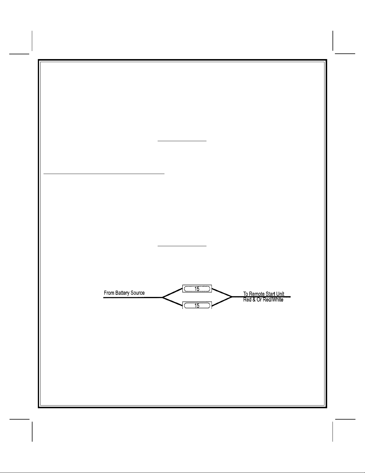
IT IS THE RESPONSIBILITY OF THE INSTALLING TECHNICIAN TO DETERMINE THE LOAD FACTOR OF THE
VEHICLES ELECTRICAL CIRCUITS WHEN THE VEHICLE IS RUNNING AND TO ADEQUATELY FUSE THE TWO
POWER WIRES BASED ON THA T LOAD. IF THE VEHICLE, RUNNING UNDER LOAD WITH THE AIR CONDITIONER,
HEATER BLOWER MOTOR, AND ACCESSORIES EXCEEDS 24 AMPS CONTINUOUS, WE RECOMMEND THAT
TWO FUSES BE USED IN COMBINA TION ON EACH POWER WIRE AS SHOWN BELOW. FOR ADDITIONAL INFORMATION SEE TECH UPDATE ISSUED 9/30/96.
YELLOW WIRE: Starter Output
Careful consideration for the connection of this wire must be made to prevent the vehicle from starting while in
gear. Understanding the difference between a mechanical and an electrical Neutral Start Switch will allow you
to properly identify the circuit and select the correct installation method. In addition you will realize why the
connection of the safety wire is required for all mechanical switch configurations.
Failure to make this connection properly can result in personal injury and property damage. In all installations it is the
responsibility of the installing technician to test the remote start unit and assure that the vehicle cannot start via RF
control in any gear selection other than park or neutral.
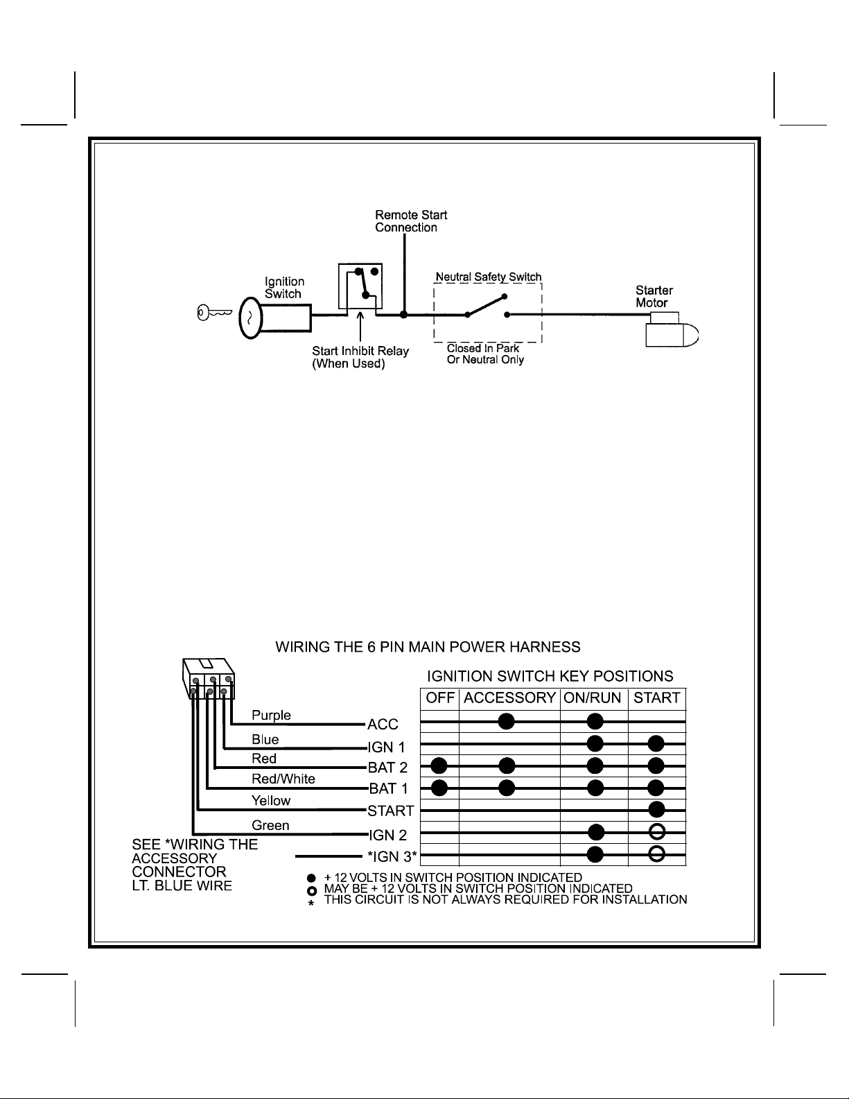
In both mechanical and electrical neutral start switch configurations, the connection of the Yellow wire will be made
to the low current start solenoid wire of the ignition switch harness. This wire will have +12 volts when the ignition
switch is turned to the start (crank) position only. This wire will have 0 volts in all other ignition switch positions.
NOTE: This wire must be connected to the vehicle side of the starter cut relay (when used). For the electrical neutral
switch configuration, this connection must be made between the starter inhibit relay, (when used) and the
neutral safety switch as shown in the following diagram.
3
128-6847A
3 of 16
Failure to connect this wire to the ignition switch side of the neutral safety switch can result in personal injury and
property damage.
SEE NEUTRAL START SAFETY TEST FOR FURTHER DET AILS.
BLUE WIRE: Ignition 1 Output
Connect this wire to the ignition 1 wire from the ignition switch. This wire will show +12 volts when the ignition key
is turned to the to the "ON" or "RUN" and the "STAR T" or CRANK" positions and will have 0 volts when the key is turned
to the "OFF" and "ACCESSORY" positions.
For Diesel Applications, this wire must be connected to the ignition circuit that powers the glow plugs if the vehicle
requires glow plug pre-heating.
GREEN WIRE: Ignition 2 Output
Connect this wire to the ignition 2 wire from the ignition switch. This wire will show + 12 volts when the ignition key
is turned to the "ON" or "RUN" position and is some cases the "START" or CRANK" position. This wire will show 0
volts when the key is turned to the "OFF" and "ACCESSORY" positions.
NOTE: See programming information concerning this wire to allow output during the "START" mode.
VIOLET WIRE: Accessory Output
Connect this wire to the Accessory wire from the ignition switch. This wire will show + 12 volts when the ignition
switch is turned to the "ACCESSORY" or "ON" and "RUN" positions and will show 0 volts when the key is turned to
the "OFF" and "STAR T" or "CRANK" positions.
4
128-6847A
4 of 16
WIRING CONNECTIONS: 12 Pin Input / Output Harness
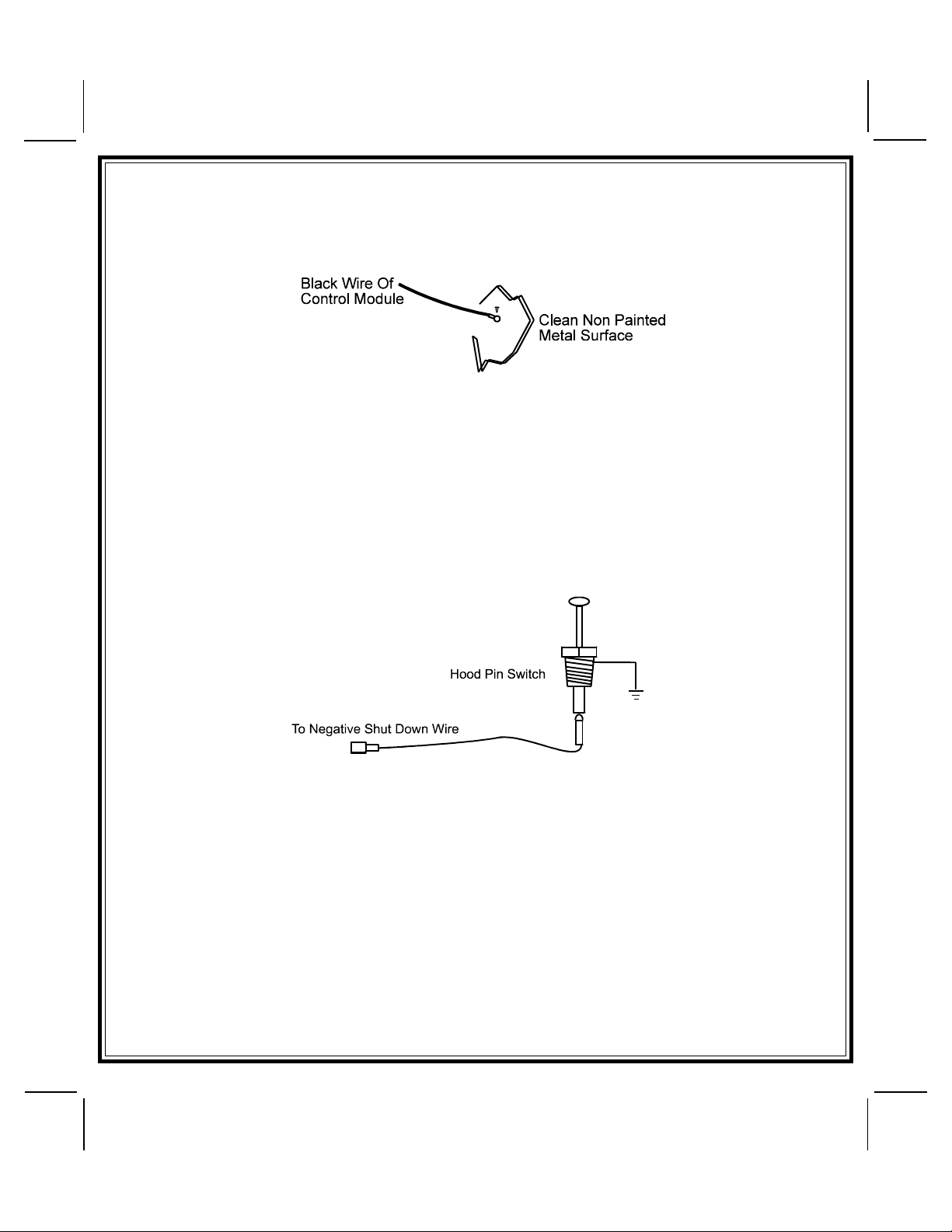
Black Wire: Chassis Ground Source
Connect the Black wire to a known vehicle ground source or to a solid clean metal part of the chassis. Be certain to
remove any paint or grease and secure this wire with a self-tapping screw and ring terminal.
BLACK w/WHITE TRACER WIRE: Control Switch
The Black w/ White tracer wire provides ON-OFF control of the Remote Starter.
When the Black w/ White wire is switched to a full time ground, the Remote Start Module is operative. When the Black
w/ White wire is at open circuit through the control switch, the remote starter is disabled.
Connect the Black w/ White tracer wire to one of the wires from the back of the previously mounted control switch. Connect
the remaining wire of the control switch to chassis ground. Always try to mount the switch so that the ON position is
in an upward or toward the driver direction.
GRAY WIRE: Negative Inhibit Input 1
Connect the GRAY wire to the previously mounted hood pin switch provided. This wire will be routed through the firewall
into the engine compartment. It is necessary to use an existing grommet when passing wires through the firewall to
prevent short circuiting. This is an important safety feature of the System, failure to use this feature can result in serious
injury. Route the wire to the pin switch and connect it using the bullet connector provided.
GRAY w/ BLACK TRACER WIRE: Negative Inhibit Input 2
Any time the gray w/ black tracer wire is grounded, the Remote Starter will stop operating, even if the signal is received
from the transmitter.
If the brake light switch in the vehicle switches ground to the brake light circuit, connect the Gray w/ Black trace wire
to the output of the brake light switch. If the brake light switch in the vehicle switches +12 Volts, do not use the Gray
w/ Black wire; see Brown w/ Black tracer wire.
BROWN WIRE: Positive Inhibit Input 1
Any time + 12 Volts is applied to the Brown wire, the Remote Starter will stop operating, even if the signal is received
from the transmitter.
If the vehicle has a factory installed hood pin switch and that switch provides + 12 Volts to an under hood light, the Brown
wire can be connected to the existing pin switch.
BROWN w/ BLACK Tracer Wire: Positive Inhibit Input 2
Any time + 12 Volts is applied to the Brown w/ Black tracer wire, the Remote Starter will stop operating, even if the signal
is received from the transmitter. If the brake light switch in the vehicle switches + 12 Volts to the brake light circuit, connect
the Brown w/ Black trace wire to the output of the brake light switch. If the brake light switch in the vehicle switches ground,
do not use the Brown w/ Black wire; see Gray w/ Black tracer wire.
5
128-6847A
5 of 16
 Loading...