

Page 1

PR400
™
Commercial Series
Portable Radio
Basic Service Manual
Page 2

Page 3

PR400 Portable Radio
Basic Service Manual
VHF 136-162 MHz
VHF 146-174 MHz
UHF 403-440 MHz
UHF 438-470 MHz
UHF 465-495 MHz
Motorola, Inc.
1301 E. Algonquin Road
Schaumburg, IL 60196
6881096C24-A
Page 4

ii
!
Foreword
This manual is intended for use by service technicians familiar with similar types of equipment. It contains
service information required for the equipment described and is current as of the printing date. Changes which
occur after the printing date may be incorporated by a complete Manual revision or alternatively as additions.
Note:
Before operating or testing these units, please read the Product Safety and RF Exposure
Compliance section.
Product Safety and RF Exposure Compliance
Note:
Before using this product, read the operating instructions for safe usage contained in the
Product Safety and RF Exposure booklet enclosed with your radio.
C a u t i o n
ATTENTION!
This radio is restricted to occupational use only to satisfy FCC RF energy exposure requirements.
Before using this product, read the RF energy awareness information and operating instructions in the
Product Safety and RF Exposure booklet enclosed with your radio (Motorola Publication part number
68P81095C98) to ensure compliance with RF energy exposure limits.
For a list of Motorola-approved antennas, batteries, and other accessories, visit the following web site which
lists approved accessories: http://www.motorola.com/cgiss/index.shtml.
Computer Software Copyrights
The Motorola products described in this manual may include copyrighted Motorola computer programs stored
in semiconductor memories or other media. Laws in the United States and other countries preserve for
Motorola certain exclusive rights for copyrighted computer programs, including, but not limited to, the
exclusive right to copy or reproduce in any form the copyrighted computer program. Accordingly, any
copyrighted Motorola computer programs contained in the Motorola products described in this manual may
not be copied, reproduced, modified, reverse-engineered, or distributed in any manner without the express
written permission of Motorola. Furthermore, the purchase of Motorola products shall not be deemed to grant
either directly or by implication, estoppel, or otherwise, any license under the copyrights, patents or patent
applications of Motorola, except for the normal non-exclusive license to use that arises by operation of law in
the sale of a product.
Document Copyrights
No duplication or distribution of this document or any portion thereof shall take place without the express
written permission of Motorola. No part of this manual may be reproduced, distributed, or transmitted in any
form or by any means, electronic or mechanical, for any purpose without the express written permission of
Motorola.
Disclaimer
The information in this document is carefully examined, and is believed to be entirely reliable. However, no
responsibility is assumed for inaccuracies. Furthermore, Motorola reserves the right to make changes to any
products herein to improve readability, function, or design. Motorola does not assume any liability arising out
of the applications or use of any product or circuit described herein; nor does it cover any license under its
patent rights nor the rights of others.
MOTOROLA and The Stylized M logo are trademarks of Motorola, Inc.
All other product or service names are the property of their respective owners.
© 2004 Motorola, Inc. All rights reserved. Printed in U.S.A.
Page 5

Table of Contents iii
Table of Contents
Foreword............................................................................................................................................ ii
Product Safety and RF Exposure Compliance ..................................................................................ii
Computer Software Copyrights..........................................................................................................ii
Document Copyrights ........................................................................................................................ ii
Disclaimer ..........................................................................................................................................ii
List of Figures ..............................................................................................vii
List of Tables ..................................................................................................x
Related Publications......................................................................................x
Chapter 1 Model Charts and Test Specifications .............................. 1-1
1.1 Radio Model Information................................................................................................................ 1-1
1.2 Model Chart for VHF1 136-174 MHz .............................................................................................1-2
1.3 Model Chart for VHF2 146-174 MHz .............................................................................................1-3
1.4 VHF Specifications ........................................................................................................................ 1-4
1.5 Model Chart for UHF1 403-440 MHz .............................................................................................1-5
1.6 Model Chart for UHF2 438-470 MHz .............................................................................................1-6
1.7 Model Chart for UHF3 465-495 MHz .............................................................................................1-7
1.8 UHF Specifications ........................................................................................................................ 1-8
1.9 MIL Standards ............................................................................................................................... 1-9
Chapter 2 Theory Of Operation ........................................................... 2-1
2.1 Introduction .................................................................................................................................... 2-1
2.2 Major Assemblies .......................................................................................................................... 2-1
2.2.1 Receiver............................................................................................................................ 2-1
2.2.2 Transmitter........................................................................................................................ 2-2
Chapter 3 Test Equipment, Service Aids, and
Service Tools....................................................................... 3-1
3.1 Test Equipment.............................................................................................................................. 3-1
3.2 Service Aids................................................................................................................................... 3-2
Chapter 4 Performance Checks .......................................................... 4-1
4.1 General .......................................................................................................................................... 4-1
4.2 Power-Up Self Test........................................................................................................................ 4-1
4.3 RF Test Mode ................................................................................................................................ 4-2
Chapter 5 Radio Alignment Procedures............................................. 5-1
5.1 Introduction .................................................................................................................................... 5-1
5.2 CPS Programming Setup .............................................................................................................. 5-1
6881096C24-A July, 2004
Page 6

iv Table of Contents
5.3 Radio Tuning Setup ....................................................................................................................... 5-2
5.3.1 Initial Test Equipment Control Settings ............................................................................. 5-3
5.4 Transmitter Alignment Options ...................................................................................................... 5-3
5.4.1 Reference Oscillator Warp................................................................................................ 5-3
5.4.2 Modulation Balance Attenuation ....................................................................................... 5-4
5.4.3 Transmit Power Tuning..................................................................................................... 5-5
5.4.3.1 To Perform Transmit High Power Tuning, do the following: .............................. 5-7
5.4.3.2 To Perform Transmit Low Power Tuning, do the following: - ............................. 5-7
5.4.4 VCO Attenuation ............................................................................................................... 5-8
5.4.4.1 VCO Attenuation 25 kHz.................................................................................... 5-8
5.4.4.2 VCO Attenuation 12.5 kHz................................................................................. 5-9
5.4.4.3 VCO Attenuation 20 kHz.................................................................................... 5-9
5.4.5 DTMF Deviation Tuning .................................................................................................. 5-10
5.4.6 MDC1200 Deviation Tuning (MDC radios only).............................................................. 5-11
5.5 Receiver Tuning........................................................................................................................... 5-11
5.5.1 Rated Volume Tuning ..................................................................................................... 5-12
5.5.2 Squelch Tuning ............................................................................................................... 5-13
5.5.2.1 Manual Squelch Tuning ................................................................................... 5-13
5.5.2.2 Auto Tune ........................................................................................................ 5-14
5.5.3 RSSI System Level Tuning ............................................................................................. 5-14
5.5.4 RSSI Display Tuning....................................................................................................... 5-15
5.6 Utilities ......................................................................................................................................... 5-15
5.6.1 Program Serial No. .........................................................................................................5-15
5.6.2 Temp Comp Data Read .................................................................................................. 5-15
5.6.3 Temp Comp Data Write .................................................................................................. 5-15
5.7 Radio-to-Radio Cloning................................................................................................................ 5-15
Chapter 6 Full Keypad Model Disassembly and
Re-assembly ........................................................................ 6-1
6.1 Introduction .................................................................................................................................... 6-1
6.2 Preventive Maintenance ................................................................................................................ 6-1
6.2.1 Inspection.......................................................................................................................... 6-1
6.2.2 Cleaning Procedures ........................................................................................................6-1
6.3 Safe Handling of CMOS and LDMOS Devices .............................................................................. 6-2
6.4 Disassembling and Re-assembling the Radio — General............................................................. 6-3
6.4.1 Radio Disassembly — Detailed ........................................................................................ 6-3
6.4.1.1 Front Cover From Chassis Disassembly ........................................................... 6-3
6.4.1.2 Dust Cover Disassembly.................................................................................... 6-6
6.4.1.3 Speaker and Microphone Disassembly ............................................................. 6-6
6.4.1.4 Keyboard Removal ............................................................................................ 6-7
6.4.1.5 PTT Disassembly............................................................................................... 6-7
6.4.1.6 Chassis Disassembly......................................................................................... 6-8
6.4.2 Radio Re-assembly - Detailed .......................................................................................... 6-9
6.4.2.1 Dust Cover Re-assembly ................................................................................... 6-9
6.4.2.2 Microphone and Speaker Re-assembly............................................................. 6-9
6.4.2.3 Keypad and LCD/Keyboard Re-assembly ....................................................... 6-11
6.4.2.4 Keyboard Retainer Re-assembly ..................................................................... 6-12
6.4.2.5 Chassis Assembly/Re-assembly...................................................................... 6-12
6.4.2.6 Chassis and Front Cover Re-assembly ........................................................... 6-13
6.4.2.7 PTT Re-assembly ............................................................................................ 6-15
6.5 Mechanical View and Parts List ................................................................................................... 6-16
6.5.1 PR400 Full-Keypad Exploded View and Parts List ......................................................... 6-16
July, 2004 6881096C24-A
Page 7

Table of Contents v
Chapter 7 Limited Keypad Model Disassembly and
Re-assembly ........................................................................ 7-1
7.1 Introduction .................................................................................................................................... 7-1
7.2 Preventive Maintenance ................................................................................................................ 7-1
7.2.1 Inspection ......................................................................................................................... 7-1
7.2.2 Cleaning Procedures ........................................................................................................7-1
7.3 Safe Handling of CMOS and LDMOS Devices.............................................................................. 7-2
7.4 Disassembling and Re-assembling the Radio — General............................................................. 7-3
7.4.1 Radio Disassembly — Detailed ........................................................................................ 7-3
7.4.1.1 Front Cover from Chassis Disassembly ............................................................ 7-3
7.4.1.2 Dust Cover Disassembly ................................................................................... 7-6
7.4.1.3 Speaker and Microphone Disassembly ............................................................. 7-6
7.4.1.4 Keyboard Removal ............................................................................................ 7-7
7.4.1.5 PTT Disassembly............................................................................................... 7-8
7.4.2 Chassis Disassembly........................................................................................................7-8
7.4.3 Radio Re-assembly - Detailed .......................................................................................... 7-9
7.4.3.1 Dust Cover Re-assembly................................................................................... 7-9
7.4.3.2 Microphone and Speaker Re-assembly............................................................. 7-9
7.4.3.3 Keypad and LCD/Keyboard Re-assembly ....................................................... 7-11
7.4.3.4 Keyboard Retainer Re-assembly..................................................................... 7-12
7.4.3.5 Chassis Assembly/Re-assembly ..................................................................... 7-12
7.4.3.6 Chassis and Front Cover Re-assembly ........................................................... 7-13
7.4.3.7 PTT Re-assembly ............................................................................................ 7-15
7.5 Mechanical View and Parts List ................................................................................................... 7-16
7.5.1 PR400 Limited-Keypad Exploded View and Parts List ................................................... 7-16
Chapter 8 Non-Keypad Model Disassembly and
Re-assembly ........................................................................ 8-1
8.1 Introduction .................................................................................................................................... 8-1
8.2 Preventive Maintenance ................................................................................................................ 8-1
8.2.1 Inspection ......................................................................................................................... 8-1
8.2.2 Cleaning Procedures ........................................................................................................8-1
8.3 Safe Handling of CMOS and LDMOS Devices.............................................................................. 8-2
8.4 Disassembling and Re-assembling the Radio — General............................................................. 8-3
8.4.1 Radio Disassembly — Detailed ........................................................................................ 8-3
8.4.1.1 Front Cover From Chassis Disassembly ........................................................... 8-3
8.4.1.2 Dust Cover Disassembly ................................................................................... 8-5
8.4.1.3 Speaker and Microphone Disassembly ............................................................. 8-6
8.4.1.4 PTT Disassembly............................................................................................... 8-6
8.4.2 Chassis Disassembly........................................................................................................8-7
8.4.3 Radio Re-assembly - Detailed .......................................................................................... 8-8
8.4.3.1 Dust Cover Re-assembly................................................................................... 8-8
8.4.3.2 Microphone and Speaker Re-assembly............................................................. 8-8
8.4.3.3 Chassis Assembly/Re-assembly ....................................................................... 8-9
8.4.3.4 Chassis and Front Cover Re-assembly ........................................................... 8-10
8.4.3.5 PTT Re-assembly............................................................................................ 8-12
8.5 Mechanical View and Parts List ................................................................................................... 8-13
8.5.1 PR400 Non-Keypad Exploded View and Parts List ........................................................ 8-13
6881096C24-A July, 2004
Page 8

vi Table of Contents
Chapter 9 Troubleshooting Tables ..................................................... 9-1
9.1 Power-Up Error Codes................................................................................................................... 9-1
9.2 Operational Error Codes ................................................................................................................ 9-1
9.3 Troubleshooting Table for Receiver............................................................................................... 9-2
9.4 Troubleshooting Table for Transmitter........................................................................................... 9-3
Appendix A Accessories .........................................................................A-1
Appendix B Warranty, Service Support, and Replacement Parts .......B-1
1.1 Scope of Manual ............................................................................................................................ 1-1
1.2 Warranty ........................................................................................................................................ 1-1
1.2.1 Warranty Period and Return Instructions.......................................................................... 1-1
1.2.2 After Warranty Period ....................................................................................................... 1-1
1.3 Replacement Parts Ordering ......................................................................................................... 1-1
1.3.1 Basic Ordering Information ............................................................................................... 1-1
1.3.2 Motorola Online................................................................................................................. 1-2
1.3.3 Mail Orders ....................................................................................................................... 1-2
1.3.4 Telephone Orders ............................................................................................................. 1-2
1.3.5 Fax Orders ........................................................................................................................ 1-2
1.3.6 Parts Identification ............................................................................................................ 1-2
1.3.7 Product Customer Service ................................................................................................ 1-3
1.4 Technical Support .......................................................................................................................... 1-3
Glossary......................................................................................................G-1
July, 2004 6881096C24-A
Page 9

Table of Contents vii
List of Figures
Figure 2-1. Major Assemblies Block Diagram..................................................................................... 2-1
Figure 2-2. Transceiver Block Diagram .............................................................................................. 2-2
Figure 3-1. Programming/Test Cable ................................................................................................. 3-4
Figure 3-2. Wiring of the Connectors.................................................................................................. 3-4
Figure 4-1. Radio Performance Checks Setup ................................................................................... 4-1
Figure 4-2. Side Button Locations ...................................................................................................... 4-2
Figure 5-1. CPS Programming Setup ................................................................................................. 5-1
Figure 5-2. Radio Tuning Setup.......................................................................................................... 5-2
Figure 5-3. Reference Oscillator Warp Window ................................................................................. 5-3
Figure 5-4. Modulation Balance Window ............................................................................................5-5
Figure 5-5. Transmit Power Window (High Power) ............................................................................ 5-6
Figure 5-6. VCO Attenuation Window (12.5 kHz) ............................................................................... 5-8
Figure 5-7. DTMF Deviation Tuning Window.................................................................................... 5-10
Figure 5-8. MDC1200 Deviation Tuning Window ............................................................................. 5-11
Figure 5-9. Rated Volume Tuning Window....................................................................................... 5-12
Figure 5-10. Squelch Tuning Window................................................................................................. 5-13
Figure 5-11. RSSI Tuning ................................................................................................................... 5-14
Figure 5-12. Side Button Locations .................................................................................................... 5-16
Figure 6-1. Battery Removal............................................................................................................... 6-3
Figure 6-2. Antenna and Knob Removal ............................................................................................ 6-4
Figure 6-3. Chassis Removal ............................................................................................................. 6-4
Figure 6-4. Keyboard Flex Connection ............................................................................................... 6-5
Figure 6-5. Microphone and Speaker Connections ............................................................................ 6-5
Figure 6-6. Dust Cover Disassembly .................................................................................................. 6-6
Figure 6-7. Removal Speaker-Microphone Assembly ........................................................................ 6-6
Figure 6-8. Keypad Removal .............................................................................................................. 6-7
Figure 6-10. Removal of Main Board from Chassis.............................................................................. 6-8
Figure 6-9. PTT Removal ................................................................................................................... 6-8
Figure 6-11. Dust Cap Re-assembly .................................................................................................... 6-9
Figure 6-13. Speaker Re-assembly .................................................................................................... 6-10
Figure 6-12. Microphone Re-assembly............................................................................................... 6-10
Figure 6-14. Keypad Re-assembly ..................................................................................................... 6-11
Figure 6-15. LCD/Keypad Board Re-assembly .................................................................................. 6-11
Figure 6-16. Keyboard Retainer Re-assembly ................................................................................... 6-12
Figure 6-17. Main Board onto Chassis Re-assembly ......................................................................... 6-13
Figure 6-19. Keyboard Flex Cable Connection................................................................................... 6-14
Figure 6-18. Microphone and Speaker Wires Re-assembly ............................................................... 6-14
Figure 6-20. Fastening the Chassis.................................................................................................... 6-15
Figure 6-21. PTT Re-assembly........................................................................................................... 6-15
Figure 6-22. PR400 Full Keypad Radio Exploded View ..................................................................... 6-16
Figure 7-1. Battery Removal............................................................................................................... 7-3
Figure 7-2. Antenna and Knob Removal ............................................................................................ 7-4
Figure 7-3. Chassis Removal ............................................................................................................. 7-4
Figure 7-4. Keyboard Flex Connector................................................................................................. 7-5
Figure 7-5. Microphone and Speaker Connections ............................................................................ 7-5
Figure 7-6. Dust Cover Disassembly .................................................................................................. 7-6
Figure 7-7. Removal Speaker-Microphone Assembly ........................................................................ 7-6
Figure 7-8. Keypad Removal .............................................................................................................. 7-7
Figure 7-9. PTT Removal ................................................................................................................... 7-8
Figure 7-10. Removal of Main Board from Chassis.............................................................................. 7-9
6881096C24-A July, 2004
Page 10

viii Table of Contents
Figure 7-11. Dust Cap Re-assembly..................................................................................................... 7-9
Figure 7-12. Microphone Re-assembly............................................................................................... 7-10
Figure 7-13. Speaker Re-assembly .................................................................................................... 7-10
Figure 7-14. Keypad Re-assembly ..................................................................................................... 7-11
Figure 7-15. LCD/Keypad Board Re-assembly................................................................................... 7-11
Figure 7-16. Keyboard Retainer Re-assembly.................................................................................... 7-12
Figure 7-17. Installation of Main Board onto Chassis ......................................................................... 7-13
Figure 7-18. Microphone and Speaker Wires ..................................................................................... 7-14
Figure 7-19. Keyboard Flex Cable Connection................................................................................... 7-14
Figure 7-20. Fastening the Chassis .................................................................................................... 7-15
Figure 7-21. PTT Re-assembly........................................................................................................... 7-15
Figure 7-22. PR400 Limited Keypad Radio Exploded View................................................................ 7-16
Figure 8-1. Battery Removal ............................................................................................................... 8-3
Figure 8-2. Antenna and Knob Removal.............................................................................................8-4
Figure 8-3. Chassis Removal.............................................................................................................. 8-4
Figure 8-4. Microphone and Speaker Connections ............................................................................ 8-5
Figure 8-5. Dust Cover Disassembly .................................................................................................. 8-5
Figure 8-6. Removal Speaker-Microphone Assembly ........................................................................ 8-6
Figure 8-8. Removal of Main Board from Chassis .............................................................................. 8-7
Figure 8-7. PTT Removal.................................................................................................................... 8-7
Figure 8-9. Dust Cap Re-assembly..................................................................................................... 8-8
Figure 8-10. Microphone Re-assembly................................................................................................. 8-8
Figure 8-11. Speaker Re-assembly ...................................................................................................... 8-9
Figure 8-12. Installation of Main Board onto Chassis ......................................................................... 8-10
Figure 8-13. Microphone and Speaker Wires Re-assembly ............................................................... 8-11
Figure 8-14. Fastening the Chassis .................................................................................................... 8-11
Figure 8-15. PTT Re-assembly........................................................................................................... 8-12
Figure 8-16. PR400 Non-Keypad Radio Exploded View .................................................................... 8-13
July, 2004 6881096C24-A
Page 11

Table of Contents ix
List of Tables
Table 1-1. Radio Model Number (Example: AAH65KDC9AA2AN) ................................................... 1-1
Table 1-2. MIL STDS 810 C, D, E, and F: Applicable to UHF and VHF Specifications
(8.2 and 8.4) ..................................................................................................................... 1-9
Table 3-1. Recommended Test Equipment....................................................................................... 3-1
Table 3-2. Service Aids ..................................................................................................................... 3-2
Table 3-3. Recommended Service Tools .......................................................................................... 3-2
Table 4-1. Initial Equipment Control Settings ....................................................................................4-2
Table 4-2. Test Environments ........................................................................................................... 4-3
Table 4-3. Test Channel Spacing ...................................................................................................... 4-3
Table 4-5. Receiver Performance Checks......................................................................................... 4-4
Table 4-4. Test Frequencies.............................................................................................................. 4-4
Table 4-6. Transmitter Performance Checks..................................................................................... 4-5
Table 5-1. Initial Equipment Control Settings ....................................................................................5-3
Table 5-2. Reference Oscillator Specifications.................................................................................. 5-4
Table 5-3. Transmit High/Low Power Level....................................................................................... 5-7
Table 5-4. Deviation Specifications ................................................................................................ 5-10
Table 5-5. Squelch Deviation Values ..............................................................................................5-13
Table 9-1. Power-Up Error Code Display .......................................................................................... 9-1
Table 9-2. Operational Error Code Display ....................................................................................... 9-1
Table 9-3. Receiver Troubleshooting Table ...................................................................................... 9-2
Table 9-4. Transmitter Troubleshooting Table .................................................................................. 9-3
Related Publications
PR400 Detailed Service Manual .........................................................................681096C25
PR400 Full-Keypad Model User Guide ...............................................................681096C23
PR400 Limited-Keypad Model User Guide .........................................................681096C26
PR400 Non-Display Model User Guide............................................................... 681096C27
PR400 User Guide CDROM.................................................................................HKLN4219
6881096C24-A July, 2004
Page 12

x Table of Contents
This Page Intentionally Left Blank
July, 2004 6881096C24-A
Page 13
Chapter 1 Model Charts and Test Specifications
1.1 Radio Model Information
The model number and serial number are locate d on a label attached to the back of y our radio. You
can determine the RF output power , frequency ban d, protocols , and ph ysica l pac kages . The example
below shows one portable radio model number and its specific characteristics.
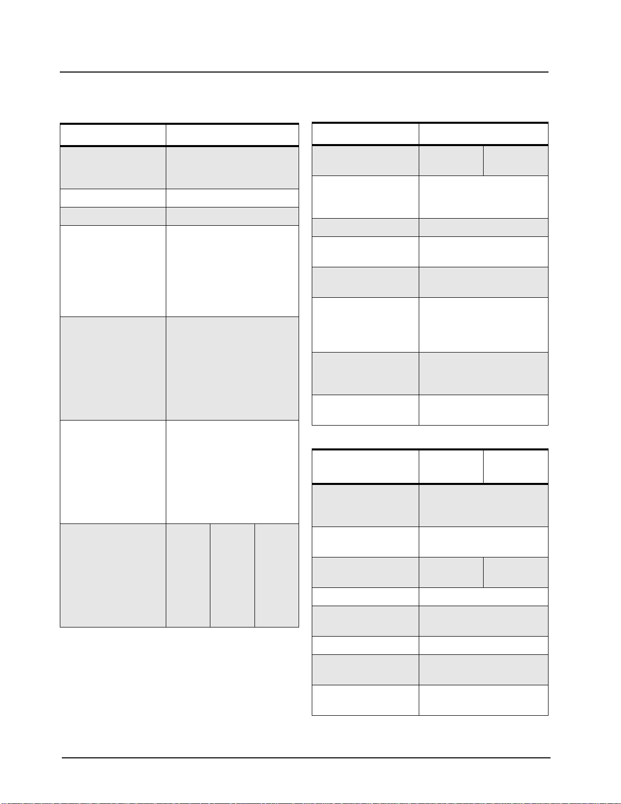
Table 1-1. Radio Model Number (Example: AAH65KDC9AA2AN)
Type of
Unit
AA H 65 J
AA = Motorola Internal Use
Model
Series
H = Portable
Freq.
Band
VHF
(136-162
MHz)
VHF
(146-174
MHz)
(403-440
MHz)
UHF
(438-470
MHz)
UHF
(465-495
MHz)
Power
Level
4 W or
5 W
K
Q
R
S
D
Physical
Packages
C
Non
Display
F
Limited
Keypad
H
Full
Keypad
Channel
Spacing
9
Pro-
gramma-
ble
Protocol
AA
Conven-
tional
Feature
Level
1AN
Model
Revision
Model
Package
Page 14
1-2 Model Charts and Test Specifications: Model Chart for VHF1 136-174 MHz
1.2 Model Chart for VHF1 136-174 MHz
PR400, VHF1, 136-162 MHz
Model Description
AAH65JDC9AA2AN PR400, 136-162 MHz, 5 W, 16 Ch. Non-Display Model
AAH65JDF9AA3AN PR400, 136-162 MHz, 5 W, 32 Ch. Limited Keypad Model
AAH65JDH9AA4AN PR400, 136-162 MHz, 5 W, 64 Ch. Full Keypad Model
Item Description
X PMUD2051_ PR400, 136- 162 MHz, 5 W, 16 Ch. Non-Display Model
X PMUD2052_ PR400, 136- 162 MHz, 5 W, 32 Ch. Limited Keypad Model
X PMUD2053_ PR400, 136-162 MHz, 5 W, 64 Ch. Full Keypad Model
X PMLD4276_ Non-Display, Back Cover Kit. 16 Ch.
X PMLD4277_ Limited Keypad, Back Cover Kit, 32 Ch.
X PMLN4278_ Full Keypad, Back Cover Kit, 64 Ch. 136-162 MHz
X PMLN4601_ Non-Display, Front Housing Kit, 16 Ch.
X PMLN4602_ Limited Keypad, Front Ho using Kit, 32 Ch.
X PMLN4603_ Full Keyp ad, Front Housing Kit, 64 Ch.
X X X NNTN4496_R NiCd Battery, 1100 mAH
X X X NNTN4497_R Li-Ion Battery, 1800 mAH
X X X NNTN4851_ NiMh Battery, 1400 mAH
X X X NNTN4852_ NiMh Battery, 1300 mAH FM
X X X NNTN4970 Slim Li-Ion Battery, 1600 mAH
X X X WPLN4138_R Rapid 90-Min. Desktop Charger w/US Plug
X X X HLN8255 3” Belt Clip
X X X NAD6502_R Antenna, 146-174 MHz, 14cm
X 6881096C27 PR400, Non-Display User Guide
X 6881096C26 PR400, Limited Keypad User Guide
X 6881096C23 PR400, Full Keypad User Guide
X X X HKLN4219 PR400, User Guide CDROM
X = Indicates compatibility with model(s)
August, 2004 6881096C24-A
Page 15

Model Charts and Test Specifications: Model Chart for VHF2 146-174 MHz 1-3
1.3 Model Chart for VHF2 146-174 MHz
PR400, VHF2, 146-174 MHz
Model Description
AAH65KDC9AA2AN PR400, 146-174 MHz, 5 W, 16 Ch. Non-Display Model
AAH65KDF9AA3AN PR400, 146-174 MHz, 5 W, 32 Ch. Limited Keypad Model
AAH65KDH9AA4AN PR400, 146-174 MHz, 5 W, 64 Ch. Full Keypad Model
Item Description
X PMUD2054_ PR400, 146-174 MHz, 5 W, 16 Ch. Non-Display Model
X PMUD2055_ PR400, 146-174 MHz, 5 W, 32 Ch. Limited Keypad Model
X PMUD2056_ PR400, 146-174 MHz, 5 W, 64 Ch. Full Keypad Model
X PMLD4279_ Non-Display, Back Cover Kit, 16 Ch,
X PMLD4280_ Limited Keypad, Back Cover Kit, 32 Ch,
X PMLN4281_ Full Keypad, Back Cover Kit, 64 Ch,
X PMLN4601_ Non-Display, Front Housing Kit, 16 Ch.
X PMLN4602_ Limited Keypad, Front Housing Kit, 32 Ch.
X PMLN4603_ Full Keypad, Front Housing Kit, 64 Ch.
X X X NNTN4496_R NiCd Battery, 1100 mAH
X X X NNTN4497_R Li-Ion Battery, 1800 mAH
X X X NNTN4851_ NiMh Battery, 1400 mAH
X X X NNTN4852_ NiMh Battery, 1300 mAH FM
X X X NNTN4970 Slim Li-Ion Battery, 1600 mAH
X X X WPLN4138_R Rapid 90-Min. Desktop Charger w/US Plug
X X X HLN8255 3” Belt Clip
X X X NAD6502_R Antenna, 146-174 MHz, 14cm
X 6881096C27 PR400, Non-Display User Guide
X 6881096C26 PR400, Limited Keypad User Guide
X 6881096C23 PR400, Full Keypad User Guide
X X X HKLN4219 PR400, User Guide CDROM
X = Indicates compatibility with model(s)
6881096C24-A August, 2004
Page 16
1-4 VHF Specifications
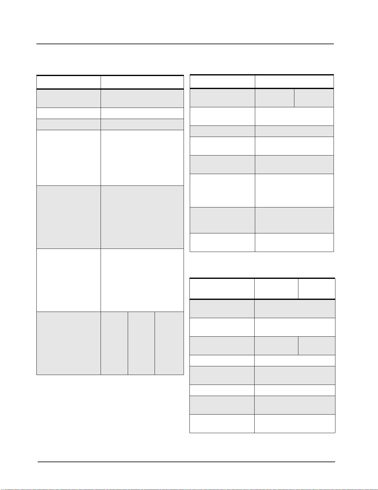
1.4 VHF Specifications
General
VHF
Frequency: 136-162 MHz
146-174 MHz
Channel Capacity: 16, 32, or 64 Channels
Power Supply: 7.5 Volts ±20%
Dimensions:
with
High Capacity NiCd,
High Capacity Li-Ion,
NiMH FM, NiMH Std,
and Slim Li-Ion
Batteries:
Weight: for 16
Channel Model
Batteries:
High Capacity NiCd
High Capacity Li-Ion
NiMH FM
NiMH Std
Slim Li-Ion
Weight: for 32 & 64
Channel Model
Batteries:
High Capacity NiCd
High Capacity Li-Ion
NiMH FM
NiMH Std
Slim Li-Ion
Average Battery Life
@ (5-5-90 Duty
Cycle):
High Capacity NiCd
High Capacity Li-Ion
NiMH FM
NiMH Std
Slim Li-Ion
130.5mm H x 62mm W x
45mm D
(5.12” H x 2.4” W x 1.75” D)
430g (15.17 oz.)
376g (13.26 oz.)
449g (15.83 oz.)
446g (15.73 oz.)
337g (13.30 oz.)
451g (15.91 oz.)
396g (13.97 oz.)
469g (16.54 oz.)
467g (16.47 oz.)
397g (14.0 oz.)
Capacity
(mAh)
1100
1800
1300
1400
1600
5 W
8 Hrs.
14 Hrs.
9 Hrs.
10 Hrs.
12 Hrs.
1 W
9 Hrs.
19 Hrs.
11 Hrs.
13 Hrs.
17 Hrs.
Transmitter
VHF
RF Output
NiMH @ 7.5 V:
Frequency: 136-162 MHz
Channel Spacing: 12.5/20/25 kHz
Freq. Stability:
(-30°C to +60°C)
Spurs/Harmonics: -36 dBm < 1 GHz
Audio Response:
(from 6 dB/oct.
Pre-emphasis, 300 to
3000 Hz)
Audio Distortion:
@ 1000 Hz, 60%
Rated Max. Dev.
FM Noise: -40 dB (12.5 kHz)
Low
1 W
146-174 MHz
0.00025%
-30 dBm > 1 GHz
+1, -3 dB
<3%
-45 dB (25 kHz)
High
5 W
Receiver
VHF
12.5 kHz
Frequency: 136-162 MHz
146-174 MHz
Sensitivity
12 dB EIA SINAD:
Adjacent Channel
Selectivity:
Intermodulation: - 70 dB
Freq. Stability
(-30°C to +60°C):
0.25 µV (typical)
-65 dB -70 dB
0.00025%
20/25kHz
VHF
Spur Rejection: -75 dB
Image and 1/2 I-F
Rejection:
Audio Output
@ <5% Distortion:
All specifications are subject to change without notice.
August, 2004 6881096C24-A
-70 dB
500 mW
Page 17
Model Charts and Test Specifications: Model Chart for UHF1 403-440 MHz 1-5
1.5 Model Chart for UHF1 403-440 MHz
PR400, UHF1, 403-440 MHz
Model Description
AAH65QDC9AA2AN PR400, 403-440 MHz, 4 W, 16 Ch. Non-Display Model
AAH65QDF9AA3AN PR400, 403-440 MHz, 4 W, 32 Ch. Limited Keypad Model
AAH65QDH9AA4AN PR400, 403-440 MHz, 4 W, 64 Ch. Full Keypad Model
Item Description
X PMUE2361_ PR400, 403-440 MHz, 4 W, 16 Ch. Non-Display Model
X PMUE2362_ PR400, 403-440 MHz, 4 W, 32 Ch. Limited Keypad Model
X PMUE2363_ PR400, 403-440 MHz, 4 W, 64 Ch. Full Keypad Model
X PMLE4338_ Non-Display, Back Cove r Kit, 16 Ch,
X PMLE4377_ Limited Keypad, Back Cover Kit, 32 Ch,
X PMLE4334_ Full Keypad, Back Cover Kit. 64 Ch,
X PMLN4601_ Non-Display, Front Housing Kit, 16 Ch.
X PMLN4602_ Limited Keypad, Front Housing Kit, 32 Ch.
X PMLN4603_ Full Keypad, Front Housing Kit, 64 Ch.
X X X NNTN4496_R NiCd Battery, 1100 mAH
X X X NNTN4497_R Li-Ion Batt ery, 1800 mAH
X X X NNTN4851_ NiMh Battery, 1400 mAH
X X X NNTN4852_ NiMh Battery, 1300 mAH FM
X X X NNTN4970 Slim Li-Ion Battery, 1600 mAH
X X X WPLN4138_R Rapid 90-Min. Desktop Charger w/US Plug
X X X HLN8255 3” Belt Clip
X X X NAE6483_R Antenna, Flexible Whip, 403-520 MHz
X 6881096C27 PR400, Non-Display User Guide
X 6881096C26 PR400, Limited Keypad User Guide
X 6881096C23 PR400, Full Keypad User Guide
X X X HKLN4219 PR400, User Guide CDROM
X = Indicates compatibility with model(s)
6881096C24-A August, 2004
Page 18

1-6 Model Charts and Test Specifications: Model Chart for UHF2 438-470 MHz
1.6 Model Chart for UHF2 438-470 MHz
PR400, UHF2, 438-470 MHz
Model Description
AAH65RDC9AA2AN PR400, 438-470 MHz, 4 W, 16 Ch. Non-Display Model
AAH65RDF9AA3AN PR400, 438-470 MHz, 4 W, 32 Ch. Limited Keypad Model
AAH65RDH9AA4AN PR400, 438-470 MHz, 4 W, 64 Ch . Full Keypad Model
Item Description
X PMUE2364_ PR400, 438-470 MHz, 4 W, 16 Ch. Non-Display Model
X PMUE2365_ PR400, 438-470 MHz, 4 W, 32 Ch. Limited Keypad Model
X PMUE2366_ PR400, 438-470 MHz, 4 W, 64 Ch. Full Keypad Model
X PMLE4340_ Non-Display, Back Cover Kit. 16 Ch.
X PMLE4378_ Limited Keypad, Back Cover Kit, 32 Ch.
X PMLE4335_ Full Keypad, Back Cover Kit, 64 Ch.
X PMLN4601_ Non-Display, Front Housing Kit, 16 Ch.
X PMLN4602_ Limited Keypad, Front Ho using Kit, 32 Ch.
X PMLN4603_ Full Keyp ad, Front Housing Kit, 64 Ch.
X X X NNTN4496_R NiCd Battery, 1100 mAH
X X X NNTN4497_R Li-Ion Battery, 1800 mAH
X X X NNTN4851_ NiMh Battery, 1400 mAH
X X X NNTN4852_ NiMh Battery, 1300 mAH FM
X X X NNTN4970 Slim Li-Ion Battery, 1600 mAH
X X X WPLN4138_R Rapid 90-Min. Desktop Charger w/US Plug
X X X HLN8255 3” Belt Clip
X X X NAE6483_R Antenna, Flexible Whip, 403-520 MHz
X 6881096C27 PR400, Non-Display User Guide
X 6881096C26 PR400, Limited Keypad User Guide
X 6881096C23 PR400, Full Keypad User Guide
X X X HKLN4219 PR400, User Guide CDROM
X = Indicates compatibility with model(s)
August, 2004 6881096C24-A
Page 19

Model Charts and Test Specifications: Model Chart for UHF3 465-495 MHz 1-7
1.7 Model Chart for UHF3 465-495 MHz
PR400, UHF3, 465-495 MHz
Model Description
AAH65SDC9AA2AN PR400, 465-495 MHz, 4 W, 16 Ch. Non-Display Model
AAH65SDF9AA3AN PR400, 465-495 MHz, 4 W, 32 Ch. Limited Keypad Model
AAH65SDH9AA4AN PR400, 465-495 MHz, 4 W, 64 Ch. Full Keypad Model
Item Description
X PMUE2367_ PR400, 465-495 MHz, 4 W, 16 Ch. Non-Display Model
X PMUE2368_ PR400, 465-495 MHz, 4 W, 32 Ch. Limited Keypad Model
X PMUE2369_ PR400, 465-495 MHz, 4 W, 64 Ch. Full Keypad Model
X PMLE4379_ Non-Display, Back Cove r Kit. 16 Ch.
X PMLE4380_ Limited Keypad, Back Cover Kit, 32 Ch.
X PMLE4336_ Full Keypad, Back Cover Kit, 64 Ch,
X PMLN4601_ Non-Display, Front Housing Kit, 16 Ch.
X PMLN4602_ Limited Keypad, Front Housing Kit, 32 Ch.
X PMLN4603_ Full Keypad, Front Housing Kit, 64 Ch.
X X X NNTN4496_R NiCd Battery, 1100 mAH
X X X NNTN4497_R Li-Ion Battery, 1800 mAH
X X X NNTN4851_ NiMh Battery, 1400 mAH
X X X NNTN4852_ NiMh Battery, 1300 mAH FM
X X X NNTN4970 Slim Li-Ion Battery, 1600 mAH
X X X WPLN4138_R Rapid 90-Min. Desktop Charger w/US Plug
X X X HLN8255 3” Belt Clip
X X X NAE6483_R Antenna, Flexible Whip, 403-520 MHz
X 6881096C27 PR400, Non-Display User Guide
X 6881096C26 PR400, Limited Keypad User Guide
X 6881096C23 PR400, Full Keypad User Guide
X X X HKLN4219 PR400, User Guide CDROM
X = Indicates compatibility with model(s)
6881096C24-A August, 2004
Page 20
1-8 UHF Specifications
1.8 UHF Specifications
General
UHF
Frequency: 403-440 MHz
438-470 MHz
465-496 MHz
Channel Capacity: 16, 32, or 64 Channels
Power Supply: 7.5 Volts ±20%
Dimensions:
with
High Capacity NiCd,
High Capacity Li-Ion,
NiMH FM, NiMH Std,
and Slim Li-Ion
Batteries:
Weight: for 16
Channel Model
Batteries:
High Capacity NiCd
High Capacity Li-Ion
NiMH FM
NiMH Std
Slim Li-Ion
Weight: for 32 & 64
Channel Model
Batteries:
High Capacity NiCd,
High Capacity Li-Ion,
NiMH FM,
NiMH Std,
Slim Li-Ion
Average Battery Life
@ (5-5-90 Duty
Cycle):
High Capacity NiCd
High Capacity Li-Ion
NiMH FM
NiMH Std
Slim Li-Ion
130.5mm H x 62mm W x
45mm D
(5.12” H x 2.4” W x 1.75” D)
430g (15.17 oz.)
376g (13.26 oz.)
449g (15.83 oz.)
446g (15.73 oz.)
337g (13.30 oz.)
451g (15.91 oz.)
396g (13.97 oz.)
469g (16.54 oz.)
467g (16.47 oz.)
397g (14.0 oz.)
Capacity
(mAh)
1100
1800
1300
1400
1600
4 W
8 Hrs.
14 Hrs.
9 Hrs.
10 Hrs.
12 Hrs.
19 Hrs.
11 Hrs.
13 Hrs.
17 Hrs.
1 W
9 Hrs.
Transmitter
UHF
RF Output
NiMH @ 7.5 V:
Frequency: 403-440 MHz
Channel Spacing: 12.5/20/25 kHz
Freq. Stability:
(-30°C to +60°C)
Spurs/Harmonics: -36 dBm < 1 GHz
Audio Response:
(from 6 dB/oct. Preemphasis, 300 to
3000 Hz)
Audio Distortion:
@ 1000 Hz, 60%
Rated Max. Dev.
FM Noise: -40 dB (12.5 kHz)
Low
1 W
438-470 MHz
465-496 MHz
0.00025%
-30 dBm > 1 GHz
+1, -3 dB
<3%
-45 dB (25 kHz)
High
4 W
Receiver
UHF
12.5 kHz
Frequency: 403-440 MHz
438-470 MHz
465-496 MHz
Sensitivity
12 dB EIA SINAD:
Adjacent Channel
Selectivity:
Intermodulation: -70 dB
Freq. Stability
(-30°C to +60°C):
0.25 µV (typical)
-60 dB -70 dB
0.00025%
20/25kHz
UHF
Spur Rejection: -75 dB
Image and 1/2 I-F
Rejection:
Audio Output
@ <5% Distortion:
All specifications are subject to change without notice.
August, 2004 6881096C24-A
-70 dB
500 mW
Page 21

Model Charts and Test Specifications: MIL Standards 1-9
1.9 MIL Standards
Table 1-2. MIL STDS 810 C, D, E, and F: Applicable to UHF and VHF Specifications (8.2 and 8.4)
Military Standards 810 C, D, E, & F: Parameter s/Methods/Procedures
810C 810D 810E 810F
Applicable
MIL-STD
Low
Pressure
High Temperature
Low
Temperature
Temperature
Shock
Solar Radiation
Rain 506.1 1,2 506.2 1,2 506.3 1,2 506.4 1
Humidity 507.1 2 507.2 2,3 507.3 2,3 507.4 3
Salt Fog 509.1 1 509.2 1 509.3 1 509.4 1
Dust 510.1 1 510.2 1 510.3 1 510.4 1
Vibration 514.2 8,10 514.3 1 514.4 1 514.5 1
Shock 516.2 1,2,5 516.3 1,4 516.4 1,4 516.5 1
Methods Procedures Methods Procedures Methods Procedures Methods Procedures
500.1 1 500.2 2 500.3 2 500.4 1
501.1 1,2 501.2 1,2 501.3 1,2 501.4 1,2
502.1 1 502.2 1,2 502.3 1,2 501.4 1,2
503.1 1 503.2 1 503.3 1 503.4 1
505.1 1 505.2 1 505.3 1 505.4 1
6881096C24-A August, 2004
Page 22

1-10 Model Charts and Test Specifications: MIL Standards
This Page Intentionally Left Blank
August, 2004 6881096C24-A
Page 23
Chapter 2 Theory Of Operation
2.1 Introduction
This chapter provides a basic theory of operation for the radio components.
2.2 Major Assemblies
• Transceiver Board – contains all transmit, receive, and audio circuitry.
• Display (Limited and Full Keypad models only) – 8 characters (14 segments star burst) and 10
icons with backlighting, liquid-crystal display (LCD).
Keypad Board (Limited and Full Keypad models only) –
Limited Keypad: a 2-button menu keypad with 2-way navigation button,
Full Keypad: a 2-button menu keypad with 2-way navigation button, and a 3 x 4 alphanumeric
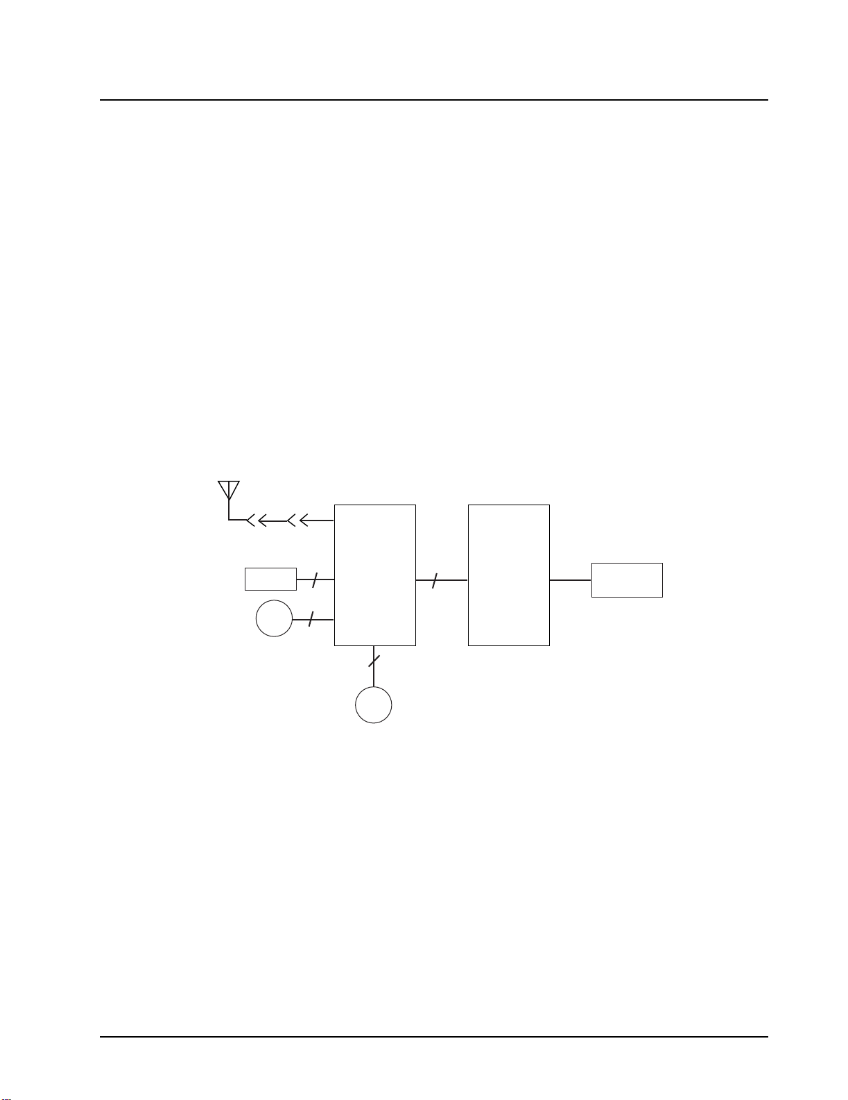
keypad.Transceiver Board (Figure 2-1).
Antenna
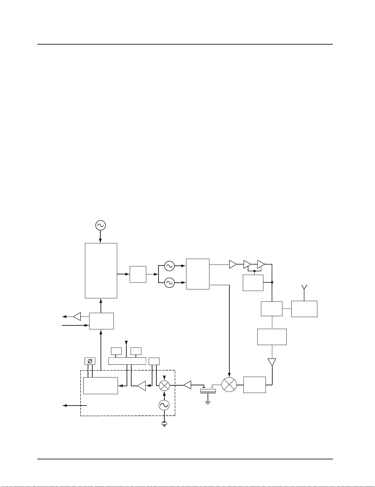
2.2.1 Receiver
Incoming RF signals from the antenna are first routed through the harmonic filter and antenna
switch, part of the transmitter circuitry, before being applied to the receiver front end. The receiver
front end consists of a preselector filter, RF amplifier, interstage filter, and a double-balanced first
mixer (Figure 2-2).
The mixer output is applied to a diplexer network which matches the 44.85 MHz IF signal to the
crystal filter, and terminates the mixer into 50 ohms at all other frequencies.
Battery
Spkr
M140
Transceiver
Board
3
J301
2
J491
Figure 2-1. Major Assemblies Block Diagram
J460
J470
2
Mic
28
Keypad
Board
J2
J1
Display
The receiver back-end is a dual conversion design. High IF selectivity is provided by a 4-pole
fundamental mode 44.85 MHz crystal filter. The output is matched to an IF amplifier stage. The
output of the IF amplifier is applied to the input of the receiver IFIC.
Page 24
2-2 Theory Of Operation: Major Assemblies
The IFIC is a low-voltage monolithic FM IF system incorporating a mixer/oscillator, two limiting IF
amplifiers, quadrature detector, logarithmic received signal strength indicator (RSSI), voltage
regulator and audio, and RSSI Op Amps. The second LO frequency, 44.395 MHz, is determined by a
crystal oscillator. The second mixer converts the 44.85 MHz high IF frequency to 455 kHz.
Additional IF selectivity is provided by two ceramic filters. The first ceramic filter is a 4-pole filter used
between the second mixer and IF amp. The second ceramic filter is a 6-pole filter and is used
between the IF amp and the limiter input. For the second ceramic filter, a wider filter is used for 20/25
kHz channel spacing, and a narrower filter is used for 12.5 kHz channels.
A ceramic resonator provides phases vs. frequency characteristic required by the quadrature
detector, with 90 degree phase shift occurring at 455 kHz. The output of the IFIC is the recovered
audio signal which is fed to the audio IC for amplification and signal conditioning. The output of the
audio IC is injecting into the audio PA which drives the 24 Ohm speaker.
2.2.2 Transmitter
• When the radio is transmitting, microphone audio is passed through the audio IC, where preemphasis and low-pass (splatter) filtering are done. The output of the audio IC is used to modulate the TX VCO, which creates the modulated carrier. The modulated carrier is then amplified
by the pre-driver and power amplifier circuit, which transmits the signal under dynamic power
control
Audio PA
Spkr
Mic
Recovered Audio
Ceramic
Resonator
RSSI
Ref. Osc.
Frac N
Mod
Audio IC
Demodulator
BW_SEL
6G
Switching
IF IC
Loop
Filter
6E
Cer Fltr
4E
Tx VCO
Circuit
Rx VCO
Circuit
VCOBIC
IF Amp
Tx Out
Rx Out
Crystal
Filter
Tx
Predriver
Mixer
PA
Module
Power
Cntr
Image
Filter
T/R
Switch
Filter
Preselector
Rx
LNA
Harmonic
Filter
Figure 2-2. Transceiver Block Diagram
July, 2004 6881096C24-A
Page 25
Chapter 3 Test Equipment, Service Aids, and
Service Tools
3.1 Test Equipment
Table 3-1 lists test equipment required to service the PR400 Radios.
Table 3-1. Recommended Test Equipment
Motorola Part No. Description Characteristics Application
R2600 series System analyzer This item will substitute for
items with an asterisk (*)
*R1074A Fluke 87 digital multi-
meter
Fluke 85 RF probe 500 MHz, 30 VAC max Use with Fluke 87 digital multi-
*R1377A AC voltmeter 1 mV to 300 mV, 10 mega-
R1611A Dual channel
100 MHz oscilloscope (Agillent)
S1339A RF millivolt meter 100 µV to 3V RF, 10 kHz to
*R1013B or
*R1370A
SINAD meter or
SINAD meter with
RMS
True RMS metering,
200 kHz frequency
counter, 32-segment bar
graph with backlit display
ohm input impedance
Two-channel, 100 MHz
bandwidth, 200 M sample
rate/sec, 2 MB memory/
channel
1 GHz frequency range
Without RMS audio voltme-
ter or
With RMS audio voltmeter
Frequency/deviation meter and
signal generator for wide-range
troubleshooting and alignment
Digital voltmeter is recommended for AC/DC voltage and
current measurements
meter for RF voltage measurements.
Audio voltage measurements
Waveform measurements
RF level measurements
Receiver sensitivity measurements
Page 26
3-2 Test Equipment, Service Aids, and Service Tools: Service Aids
3.2 Service Aids
Table 3-2 lists service aids recommended for working on the PR400 Radios. While all of these i tems
are available from Motorola, most are standard shop equipment items, and any equivalent item
capable of the same performance may be substituted for the item listed.
Table 3-2. Service Aids
Motorola P a rt
No.
RLN4460 Portable Test Set Enables connection to the audio/accessory jack.
RLN4510 Battery Interface Regulates DC current and voltage between radio and
RVN4191 Customer Programming Soft-
ware and Global Tuner Software
on CD Rom
AAPMKN4004 Programming Test Cable Connects radio to RIB (PLN4008).
AAPMKN4003 Radio to Radio Cloning Cable
RLN4008 Radio Interface Box Enables communications between the radio and the
5886564Z01 RF Adaptor Adapts radio’s antenna port to BNC cabling of test
0180305K08 Shop Battery Eliminator Interconnects radio to power supply.
HSN9412 Wall-Mounted Power Supply Used to supply power to the RIB (120 VAC).
Description Application
Allows switching for radio testing.
power supply.
Program customer option and channel data.
Allows a radio to be duplicated fr om a master radio by
transferring prog rammed d ata from the master radio to
the other.
computer’s serial communications adapter.
equipment.
3080369B71 or
3080369B72
6686533Z01 Knob Remover/Chassis Opener Used to remove the front cover assembly.
HKN9216 IBM Computer Interface Cable Connection from computer to RIB.
8180384N65 Housing Eliminator Allows testing of the radio outside of the housing.
Motorola P a rt
No.
RSX4043A TORX screwdriver Tighten and remove chassis screws
6680387A70 T6 TORX bit Removable TORX screwdriver bit
R1453A Digital readout solder station Digitally controlled soldering iron
RLN4062A Hot air workstation, 120 V Tool for hot air soldering/desoldering of surface
Computer Interface Cable Use B72 for the IBM PC AT or newer (9-pin serial
port). Use B71 for older models (25-pin serial port).
Connects the computer’s serial communications
adapter to the RIB (PLN4008).
Table 3-3. Recommended Service Tools
Description Application
mounted integrated circuits
July 21, 2004 6881096C24-A
Page 27
Test Equipment, Service Aids, and Service Tools: Service Aids 3-3
Table 3-3. Recommended Service Tools (Continued)
Motorola P art
No.
Description Application
0180386A78 Illuminated magnifying glass with
lens attachment
Illumination and magnification of components
0180302E51 Master lens system
0180386A82 Anti-static grounding kit Used during all radio assembly and disassembly pro-
cedures
6684253C72 Straight prober
6680384A98 Brush
1010041A86 Solder (RMA type), 63/67,
0.5mm diameter, 1 lb. spool
0180303E45 SMD tool kit (included with
R1319A)
R1319A ChipMaster (110 V) Surface mount removal and assembly of surface
R1321A ChipMaster (220 V)
mounted integrated circuits and/or rework station
shields. Includes 5 nozzles.
ChipMaster Nozzles:
6680332E83 PLCC-28* nozzle
6680332E82 PLCC-44* nozzle
6680332E94 PLCC-52 nozzle
6680332E96 PLCC-84 nozzle
6680334E67 QFP-160 nozzle
6680333E46 SOL-18 nozzle
6680332E84 SOIC-20 nozzle
6680332E87 SOL-20J nozzle
6680333E45 SOL-24 nozzle
6680333E55 TSOP-64 nozzle
* Included with ChipMaster packages
Soldering and Un-soldering IC’s
6881096C24-A July, 2004
Page 28

3-4 Test Equipment, Service Aids, and Service Tools: Service Aids
Programming/Test Cable
3.5mm mono
2.5mm stereo
Figure 3-1. Programming/Test Cable
P1
2.5mm stereo and
3.5mm
3.5mm Tip
(Speaker +)
3.5mm
Sleeve
2.5mm Tip
(Microphone)
2.5mm
2.5mm
Center
1
2
5
3
4
25 POSITION
MALE CONNECTOR
P2 P3
36.0”
CABLE
P1
Orange
1
Blue
2
White
25 POSITION
FEMALE CONNECTOR
36.0”
CABLE
ohm
5
1UF,16V 5%
Spiral
3
Yellow
4
25 pin Male D Connector
P2
Components molded inside
1
5
47
24
7
33K
20
8
+
15
16
9
P3
25 pin Female
D Connector
1
15
4
11
T o Test Box
T o Test Box
Figure 3-2. Wiring of the Connectors
July 21, 2004 6881096C24-A
Page 29
Chapter 4 Performance Checks
4.1 General
These radios meet published specifications through their manufacturing process by utilizing highaccuracy laboratory-quality test equipment. The recom mended field service equipment is as accur ate
as the manufacturing equipment with few exceptions. This accuracy must be maintained in
compliance with the manufacture r’s recommended calibration schedule.
Radio
Program/
PMKN4004
Figure 4-1. Radio Performance Checks Setup
4.2 Power-Up Self Test
Applying power to the r a dio by using the on/off volum e cont rol, starts a self-test routine which checks
the RAM, EEPROM hardware and EEPROM checksum. Pressing and holding SB1 while turning on
the radio causes the self-test routine to check for the ROM checksum as well. If these checks are
successfully completed, the radio will generate the Self-Test Pass Tone. If the self-test is not
successful, a Self-Test Fail Tone is heard.
Test Cable
RIB
RLN4008
RIB Power Supply
Computer Interface
Cable
Tx Data
Rx
Data
Gnd
Page 30

4-2 Performance Checks: RF Test Mode
Supply voltage can be connected from the battery eliminator. The equipment required for alignment
procedures is connected as shown in the Radio Performance Checks Setup diagram (Figure 4-1).
Initial equipment control settings should be as indicated in Table 4-1 and sh ould be the same for all
performance checks and tuner alignment procedures.
Table 4-1. Initial Equipment Control Settings
Service Monitor Test Set Power Supply
Monitor Mode: Power Monitor Spkr set: A Voltage: 7.5 Vdc
RF Attenuation: -70 Spkr/load:
AM, CW, FM: FM PTT: OFF Volt Range: 10 V
Oscilloscope Source: Mod
Oscilloscope Horiz: 1 0 mSec/Div
Oscilloscope Vert: 2.5kHz/Div
Oscilloscope Trig: Auto
Monitor Image: Hi
Monitor BW: Nar
Monitor Squelch: mid CW
Monitor Vol: 1/4 CW
4.3 RF Test Mode
When the PR400 radio is operating in its normal environment, the radio's microcomputer co nt rols t h e
RF channel selection, transmitter key-up, and receiver muting, according to the customer codeplug
configuration. However, when the unit is on the bench for testing, alignment, or repair, it must be
removed from its normal environment using a special routine, called RF TEST MODE. This mode
allows bench testing of the radio at various test frequencies across the entire band, at both high and
low transmit power (if applicable), at various channel spacings, and with differ ent coded or carrier
squelch types. Any customer specific programming in the radio will not be changed or affected by use
of the RF Test Mode..
Speaker
DC on/standby:
Standby
Current: 2.5 A
Side Button 1
P2
P1
3
2
Side Button 2
6
1
5
9
4
8
#
7
0
*
Figure 4-2. Side Button Locations
July, 2004 6881096C24-A
Page 31

Performance Checks: RF Test Mode 4-3
To enter te st mo de :
1. Turn the radio on.
Within ten seconds after the self test is complete (self test tone is heard), press SB2 (Side Button 2 in
Figure 4-2) five times in succession. If the self test complete tone is not heard, see Error Codes
information in Chapter 9. Entry into the test mode is indicated by a positive indicator tone followed by
a good key chirp (GKC) upon entering test mode, the radio is in the carrier squelch mode.
2. Press SB1 (Side Button 1) and scroll through and access test environments as shown in Table 4-
2.
3. Press SB2 and scroll through the channel spacing available as shown in Table 4-3.
4. T urn the channel selector knob to change the test chan nel f or that en vironment as sho wn in Table 4-4.
5. Press the PTT on a test channel to cause the radio to transmit at the test frequency for t he channel.
Table 4-2. Test Environments
No. of
Beeps
1
GKC*
1
BKC*
2
BKC
3
BKC
5
BKC
9
BKC
11
BCK
Description Function
Carrier Squelch RX: unsquelch if carrier detected
TX: mic audio
Tone Private-Line RX: unsquelch if carrier and tone (192.8 Hz) detected
TX: mic audio + tone (192.8 Hz)
Digital Private-Line RX: unsq uelch if carrier and digital code (131) detected
TX: mic audio + digital code (131)
Dual-Tone Multiple
Frequency
RX: unsquelch if carrier detected
TX: selected DTMF tone pair
Unsquelch Open RX: constant unsquelch
TX: mic audio
High-Speed Signaling
RX: unsquelch if carrrier detected
TX: 1500 Hz tone
Companding RX: unsquelch if carrier detected
TX: mic audio
* “BKC” means Bad K e y Chirp (low-pitche d tone), “ GKC” means Good Key Chirp (high-pitched
tone).
Table 4-3. Test Channel Spacing
No. of BKC Channel Spacing
1 25 kHz
2 12.5 kHz
3 20 kHz
6881096C24-A August, 2004
Page 32

4-4 Performance Checks: RF Test Mode
Table 4-4. Test Frequencies
Channel Selector
Switch Position
1 Low Power
8 High Power
2 Low Power
9 High Power
3 Low Power
10 High Power
4 Low Power
11 High Power
5 Low Power
12 High Power
6 Low Power
13 High Power
7 Low Power
14 High Power
T est Channel
TX#1 or #8
RX#1 or #8
TX#2 or #9
RX#2 or #9
TX#3 or #10
RX#3 or #10
TX#4 or #11
RX#4 or #11
TX#5 or #12
RX#5 or #12
TX#6 or #13
RX#6 or #13
TX#7 or #14
RX#7 or #14
VHF 1
(136-162
MHz)
136.625 146.625 403.625 438.625 465.625
140.325 150.775 409.775 443.775 470.775
144.525 155.275 415.275 448.275 475.275
148.875 160.125 421.125 454.125 480.125
153.325 164.475 427.475 459.475 485.475
157.875 169.475 433.475 464.475 490.475
161.975 173.875 439.875 469.875 494.875
VHF 2
(146-174
MHz)
UHF 1
(403-440
MHz)
UHF 2
(438-470
MHz)
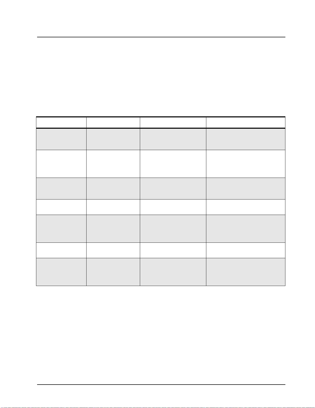
Table 4-5. Receiver Performance Checks
Test Name Communications Analyzer Radio Test Set Comments
UHF 3
(465-495
MHz)
Reference
Frequency
Mode: PWR MON
4th channel test frequency
Monitor: Frequency error
Input at RF In/Out
TEST MODE,
*
T est Channel 4
carrier squelch
output at
antenna
PTT to continuous (during the
performance
check)
Frequency error to be
±186 Hz VHF1
±200 Hz VHF2
±525 Hz UHF1
±568 Hz UHF2
±600 Hz UHF3
Rated Audio Mode: GEN
Output level: 1.0m V RF
4th channel test frequency
Mod: 1 kHz tone at
TEST MODE
T est Channel 4
*
carrier squelch
PTT to OFF
(center), meter
selector to Audio
PA
Set volume control to
3.46 Vrms
3 kHz deviation
Monitor: DVM: AC Volts
Distortion As above, except to distortion As above As above Distortion <3.0%
Sensitivity
(SINAD)
As above, except SINAD,
lower the RF level for 12 dB
As above PTT to OFF
(center)
RF input to be <0.30
µV (0.25 µV typical).
SINAD.
Noise
Squelch
Threshold
(only radios
with conventional system
need to be
tested)
RF level set to 1 mV RF As above PTT to OFF
(center), meter
selection to
Audio PA, spkr/
load to speaker
As above, except change fre-
quency to a conventional sys-
tem. Raise RF level from zero
until radio unsquelches.
out of TEST
MODE; select
a conventional
system
As above Unsquelch to occur at
Set volume control to
3.46 Vrms
<0.25 µV.
Preferred SINAD =
6-9 dB
August, 2004 6881096C24-A
Page 33

Performance Checks: RF Test Mode 4-5
* See Table 4-4
Table 4-6. Transmitter Performance Checks
T est Name Communications Analyzer Radio Test Set Comments
Reference
Frequency
Power RF As above As above As above Refer to Maintenance
Voice
Modulation
Voice
Modulation
(internal)
Mode: PWR MON
4th channel test frequency
Monitor: Frequency error
Input at RF In/Out
Mode: PWR MON
4th channel test frequency
atten to -70, input to RF In/
Out
Monitor: DVM, AC Volts
Set 1 kHz Mod Out level for
0.025 Vrms at test set,
80m Vrms at AC/DC test set
jack
Mode: PWR MON
4th channel test frequency
atten to -70, input to RF In/
Out
*
*
*
TEST MODE,
T est Channe l 4
carrier squelch
Output at
antenna
As above As above, meter
TEST MODE,
T est Channe l 4
carrier squelch
Output at
antenna
PTT to continuous (during the
performance
check)
selector to mic
Remove modulation input
Frequency error to be
±186 Hz VHF1
±200 Hz VHF2
±525 Hz UHF1
±568 Hz UHF2
±600 Hz UHF3
Specifications
Deviation:
VHF, UHF
≥ 4.0 kHz but ≤ 5.0
kHz (25 kHz Ch Sp).
Press PTT switch on
radio. Say “f our” loudly
into the radio mic.
Measure deviation:
VHF, UHF
≥ 4.0 kHz but ≤ 5.0
kHz (25 kHz Ch Sp)
DTMF
Modulation
PL/DPL
Modulation
* See Table 4-4
As above,
4th channel test frequency
As above
4th channel test frequency
BW to narrow
TEST MODE,
*
T est Channe l 4
DTMF
Output at
antenna
TEST MODE,
*
Test Channel 4
TPL
DPL
As above Deviation:
VHF, UHF
but
≤ 3.45 kHz
(25 kHz Ch Sp)
As above Deviation:
VHF, UHF
but
≤ 1000 Hz
(25 kHz Ch Sp).
≥ 3.05 kHz
≥ 500 Hz
6881096C24-A August, 2004
Page 34

4-6 Performance Checks: RF Test Mode
This Page Intentionally Left Blank
July, 2004 6881096C24-A
Page 35

Chapter 5 Radio Alignment Procedures
5.1 Introduction
This chapter provides an ov erview of the Commercial Series Customer Prog ramming Softw are (CPS)
and the Global Tuner as designed for use in a Windows® 98/NT4/2000/ME/XP environment. Both
cover all the functions of the traditional Radio Service Software (RSS) package.
They are both available in the CPS and Global Tuner (CD ROM) Kit (RVN4191).
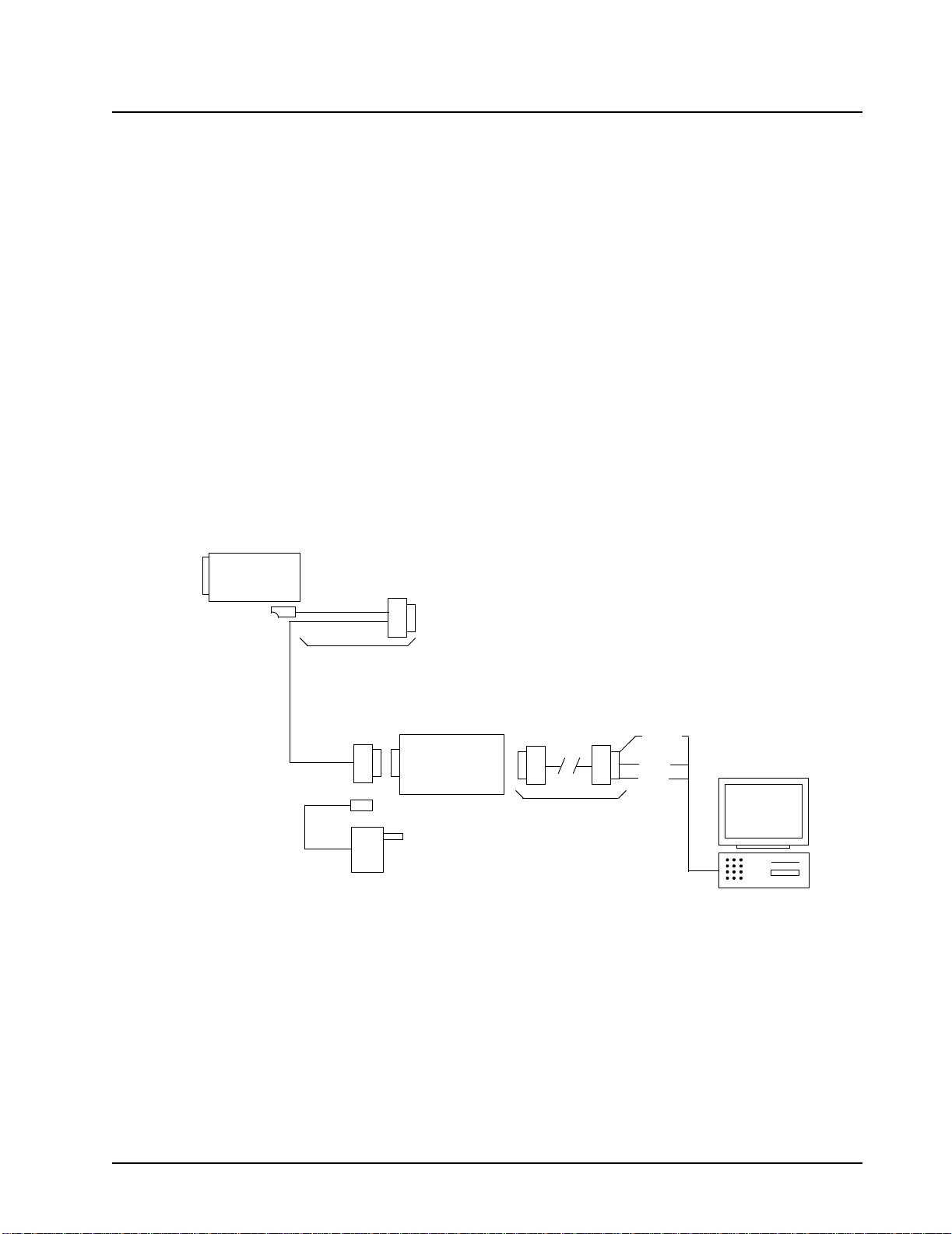
5.2 CPS Programming Setup
Refer to online help files for the CPS Programming procedures. (See Figure 5-1 for CPS
Programming Setup).
Radio
Test Box
RLN4460
Battery
Program/
Test Cable
PMKN4004
Tx Data
RIB
RLN4008
RIB Power Supply
Computer Interface
Cable
Rx
Data
Gnd
Figure 5-1. CPS Programming Setup
Page 36

5-2 Radio Alignment Procedures: Radio Tuning Setup
5.3 Radio Tuning Setup
A Windows 98/NT4/2000/ME/XP PC (personal co mputer) and Global Tuner are required to tune the
radio. To perform the tuning procedures, the radio must be connected to the PC, RIB (Radio Interface
Box) and Universal Test Set as shown in Figure 5-2 below. Refer to online help files for the tuning
procedures.
Power
Supply
Power Cable
RLN5410
Battery
Eliminator
Radio
RF Adaptor
5886564Z01
Program/
PMKN4004
Test Cable
RLN4008
BNC
Test Box
RLN4460
RIB
30 dB Pad
Transmit
30 dB Pad
RF Generator
Receive
Audio In
Computer Interface
Cable
Tx Data
Rx
Data
Gnd
Service Monitor or
Counter
Wattmeter
Tx
Audio Gener ator
Rx
Sinad Meter
AC Voltmeter
RIB Power Supply
Figure 5-2. Radio Tuning Setup
July, 2004 6881096C24-A
Page 37

Radio Alignment Procedures: Transmitter Alignment Options 5-3
5.3.1 Initial Test Equipment Control Settings
The initial test equipment control settings are listed in Table 5-1.
Table 5-1. Initial Equipment Control Settings
Service Monitor Test Set Power Supply
Monitor Mode: Power Monitor Speaker set: A Voltage: 13.2 Vdc
RF Attenuation: -70 Speaker/load:
AM, CW, FM: FM PTT: OFF Volt Range: 20 V
Oscilloscope Source: Mod
Oscilloscope Horizontal: 10 mSec/Div
Oscilloscope Vertical: 2.5 kHz/Div
Oscilloscope Trigger: Auto
Monitor Image: Hi
Monitor BW: Nar
Monitor Squelch: mid CW
Monitor Volume: 1/4 CW
5.4 Transmitter Alignment Options
Note:
5.4.1 Reference Oscillator Warp
This is an important operation which affects all deviation values such as DTMF, MDC1200 Signaling
etc. The frequency will drift if not warped properly. Perform this operation prior to all other transmit
tuning operations in order to minimize heating and because of the impact of warp on signaling
operations.
When checking the RF power output of the radio with a test set, always use a pad of
at least 30 dB attached to the radio end of the RF cable. This will avoid an RF
mismatch and ensure a stab le RF reading th at will not c hange with v arying lengths of
connecting cable.
Speaker
DC on/standby:
Standby
Current: 20 A
Figure 5-3. Reference Oscillator Warp Window
6881096C24-A July, 2004
Page 38

5-4 Radio Alignment Procedures: Transmitter Alignment Options
1. Under Tx Align menu, select Reference Oscillator Warp (Figure 5-3).
2. There is only 1 frequency point shown which is always the last non-0 transmit frequency point,
which will normally be F7.
3. Click on the slider thumb and press PTT Toggle to key up the radio at the corresponding frequency point.
4. Monitor the transmit frequency.
5. Adjust the slider, spin or edit control (press ENTER to confirm selection/send a softpot value) until
the frequency is as close as possible to the indicated transmit frequency. (Refer to Table 5-2).
6. Dekey the radio by pressing PTT Toggle.
7. Program the warp value into the radio by pressing the Program button.
8. Exit the Reference Oscillator Warp function.
Table 5-2. Reference Oscillator Specifications
RF Band Target
VHF Band 1 (136-162 MHz) ±162 Hz
VHF Band 2 (146-174 MHz) ±174 Hz
UHF Band 1 (403-440 MHz) ±436 Hz
UHF Band 2 (438-470 MHz) ±470 Hz
UHF Band 3 (465-495 MHz) ±495 Hz
5.4.2 Modulation Balance Attenuation
Note:
When using test box RLN4460:
• Inject the signal into the radio via the METER IN terminal an d
• Set the METER IN selector switch to "VOL".
• Inject the signal into the radio via th e AUDIO IN terminal.
• Set the METER OUT toggle switch to the “MIC PORT” position
• Set the METER OUT selector switch to “MIC”.
August, 2004 6881096C24-A
Page 39

Radio Alignment Procedures: Transmitter Alignment Options 5-5
Figure 5-4. Modulation Balance Window
Compensation alignment balances the modulation sensitivity of the VCO and reference modulation
(synthesizer low frequency port) lines. The compensat ion algorithm is critical to the operation of
signaling schemes that hav e v ery low frequency comp onents (Digit al Private -Line) and cou ld result in
distorted waveforms if improperly adjusted. To perform Modulation Balance tuning, follow the
following steps.
1. Under the Tx Align menu, select Mod Balance Attn (Figure 5-4).
2. Begin with the lowest freq uen cy ( i.e. the first frequency point from the t op). Pressing PTT Toggle
without selecting any slider control at the corresponding frequency point will key the radio up at
the first frequency point.
3. Inject 80 Hz at an amplitude of 1.78 V.
4. Record the deviation obtained. Typical values should range from [(1.70-2.30 kHz. Modulation is
only tuned in the 25 kHz channel spacing mode)].
5. Inject 3 kHz. Set the amplitude to 1.5 V.
6. Change the modulation balance attenuation setting until the Tx devia tion is as r ecor ded in ste p 4.
7. Inject 80 Hz at an amplitude of 1.78 V.
8. Check the deviation again. If the Tx deviation changes, record the reading and repeat steps 5-8
until the Tx deviation remains the same.
9. Press PTT Toggle to dekey the radio. Choose the next frequency, key up and repeat steps 3 to 8
until all seven tuning points are done.
10. Program the softpot value by pressing the Program button.
11. Exit the Modulation Balance Function.
5.4.3 Transmit Power Tuning
Note:
The maximum available power level given in the table below must not be exceeded.
There are separate alignment procedures for High and Low power.
6881096C24-A July, 2004
Page 40

5-6 Radio Alignment Procedures: Transmitter Alignment Options
Note: When checking the RF power output of the radio with a test set, always use a pad of
at least 30 dB attached to the radio end of the RF cable. This will avoid an RF
mismatch and ensure a stable RF reading that will not change with v arying lengths of
connecting cable
Figure 5-5. Transmit Power Window (High Power)
July, 2004 6881096C24-A
Page 41

Radio Alignment Procedures: Transmitter Alignment Options 5-7
Table 5-3. Transmit High/Low Power Level
RF Band (MHz) Model Number High Power(W) Low Power (W)
16 Channel VHF 136-162 MHz AAH65JDC9AA2AN 5.2-5.5 1.1-1.3
32 Channel VHF 136-162 MHz AAH65JDF9AA3AN 5.2-5.5 1.1-1.3
64 Channel VHF 136-162 MHz AAH65JDH9AA4AN 5.2-5.5 1.1-1.3
16 Channel VHF 146-174 MHz H65KDC9AA2AN 5.2-5.5 1.1-1.3
32 Channel VHF 146-174 MHz H65KDF9AA3AN 5.2-5.5 1.1-1.3
64 Channel VHF 146-174 MHz H65KDH9AA4AN 5.2-5.5 1.1-1.3
16 Channel UHF 1 403-440 MHz H65QDC9AA1AN 4.2-4.5 1.1-1.3
32 Channel UHF 1 403-440 MHz H65QDF9AA1AN 4.2-4.5 1.1-1.3
64 Channel UHF 1 403-440 MHz H65QDH9AA1AN 4.2-4.5 1.1-1.3
16 Channel UHF 2 438-470 MHz H65RDC9AA1AN 4.2-4.5 1.1-1.3
32 Channel UHF 2 438-470 MHz H65RDF9AA1AN 4.2-4.5 1.1-1.3
64 Channel UHF 2 438-470 MHz H65RDH9AA1AN 4.2-4.5 1.1-1.3
16 Channel UHF 3 465-495 MHz H65SDC9AA1AN 4.2-4.5 1.1-1.3
32 Channel UHF 3 465-495 MHz H65SDF9AA1AN 4.2-4.5 1.1-1.3
64 Channel UHF 3 465-495 MHz H65SDH9AA1AN 4.2-4.5 1.1-1.3
5.4.3.1 To Perform Transmit High Power Tuning, do the following:
1. Under the Tx Align menu, select Transmit Power, then select High (Figure 5-5).
2. Press PTT Toggle. This will key the radio up at 1st test frequency (F1).
3. Adjust the high power le v el t o be as defined by Table 5-3. Mov e the slider /spin control or k e ying in
values in the edit control (press ENTER to confirm your selection afte r typing in the soft pot v alue) .
4. Press PTT Toggle to dekey the radio, go to the ne xt frequency point b y selecting the slider, typing
in the edit control box (press ENTER to confirm selection after typing in the softpot value) or toggling the softpot value using the spin control.
5. Press PTT Toggle again to key up the radio at the selected frequency point.
6. Repeat steps 3-5 for the remaining test frequencies (F2-7)
7. Press Program to store the softpot values into the radio’s codeplug.
8. Exit the Transmit High Power function.
9. If the radio uses only high power channels, proceed to adjust modulation. If low power channels
are used, perform Transmit Low Power Tuning as defined.
5.4.3.2 To Perform Transmit Low Power Tuning, do the following: -
1. Under the Tx Align menu, select Transmit Power, and then select Low.
2. Press PTT Toggle. This will key the radio up at 1st test frequency (F1).
6881096C24-A August, 2004
Page 42

5-8 Radio Alignment Procedures: Transmitter Alignment Options
3. Adjust the power level to be as defined by country power level specifications by moving the
slider/spin control or keying in values in the edit control (press ENTER to confirm your selection
after typing in the softpot value).
4. Press PTT Toggle to dekey the radio , go t o the ne xt frequen cy point by selecting the slider, typing
in the edit control box (press ENTER to con firm your selection ) or toggling t he softpo t v alue u sing
the spin control.
5. Press PTT Toggle again to key up the radio at the selected frequency point.
6. Repeat steps 3-5 for the remaining test frequencies (F2-F7).
7. Press Program to store the softpot values into the radio’s codeplug.
8. Exit the Transmit Low Power function.
5.4.4 VCO Attenuation
Note: Modulation Balance Tuning must be done first. The Transmit Deviation Limit softpot
sets the maximum deviation of the carrier. Tuning is performed for all (12.5 kHz, 20
kHz and 25 kHz) channel bandwidths. Tuning for 25 kHz channels must be done first
for all frequency points. Tuning for 12.5 and 20 kHz channels determines only the offset to the previously tuned deviation for 25 kHz t uning channel spac ing. For 12.5, and
20kHz channels, only the last non-0 transmit frequency point (normally F7) is used
for tuning. The 30 kHz channel bandwidths that use 5.0 kHz maximum system deviation are covered by the 25 kHz tuning.
When using test box RLN4460:
• Set the METER OUT toggle switch to the “MIC PORT” position
• Set the METER OUT selector switch to "MIC”.
• Inject a 1 kHz tone with the levels given below for each radio model to AUDIO IN.
• Measure the level at the radio input at the AC/DC meter.
Figure 5-6. VCO Attenuation Window (12.5 kHz)
August, 2004 6881096C24-A
Page 43

Radio Alignment Procedures: Transmitter Alignment Options 5-9
5.4.4.1 VCO Attenuation 25 kHz
1. Under the Tx Align menu, select VCO Attenuation 25 kHz (Figure 5-6).
2. Begin with the lowest frequency. Select the thumb of the slider at the lowest frequency point and
then press the PTT Toggle button to key up the radio at the corresponding frequency point. The
spin control can also be toggled via its up/down arrow buttons. The softpot value can also be
typed into the edit control (press ENTER to confirm your selection/send a softpot value).
3. Inject 1 kHz at an appropriate level until 2.3 V rms is measured at the AC/DC METER (radio
input) if using test box RLN4460.
4. Record the deviation obtained.
5. Adjust the slider; adjust the spin control or key in softpot values (press ENTER to confirm) for the
frequency point until the deviation is within the range specified in Table 5-4.
6. Dekey the radio (Press the PTT Toggle button). Choose the next frequency, key up and repeat
steps 3 to 6 until all seven tuning points are done.
7. Program the softpot value by pressing the Program button.
8. Exit the VCO Attn. 25 kHz function.
5.4.4.2 VCO Attenuation 12.5 kHz
Note:
1. Under the Tx Align menu, select VCO Attenuation 12.5 kHz.
2. Press PTT Toggle to key up the radio at the last non-0 transmit frequency point ( normally F7).
3. Inject 1 kHz at an appropriate level until 2.3 V rms is measured at the AC/DC METER (radio
4. Record the deviation obtained.
5. Adjust the slider, adjust the spin cont rol or key in softpot valu es (press ENTER to confirm) for the
6. Press PTT Toggle to dekey the radio.
7. Program the softpot value by pressing the Program button.
8. Exit the VCO Attenuation 12.5 kHz function.
Tuning of Modulation Balance Attenutation and VCO Attenuation for 25 kHz channel
bandwidth must be done first.
input) if using test box RLN4460.
frequency point until the deviation is within the range specified in Table 5-4.
5.4.4.3 VCO Attenuation 20 kHz
Note:
1. Under the Tx Align menu, select VCO Attenuation 20 kHz.
2. Press PTT Toggle to key up the radio at the last non-0 transmit frequency point ( normally F7).
3. Inject 1 kHz: at an appropriate lev el until 2.3 V rms is measured at the AC/DC METER (radio
4. Record the deviation obtained.
5. Adjust the slider; adjust the spin control or key in softpot values (press ENTER to confirm) for the
6. Press PTT Toggle to dekey the radio.
7. Program the softpot value by pressing the Program button.
8. Exit the VCO Attn. 20 kHz function.
Tuning of Modulation Balance Attn. and VCO Attn. for 25 kHz channel bandwidth
must be done first.
input) if using test box RLN4460.
frequency point until the deviation is within the range specified in Table 5-4.
6881096C24-A August, 2004
Page 44

5-10 Radio Alignment Procedures: Transmitter Alignment Options
Table 5-4. Deviation Specifications
Band Channel Spacing Deviation (kHz)
UHF/VHF 25 kHz 4.40 - 4.60
UHF/VHF 12.5 kHz 2.20 - 2.30
UHF/VHF 20 kHz 3.40 - 3.60
5.4.5 DTMF Deviation Tuning
This tuning option controls the Dual Tone MultiFrequency deviation. Please note that Modulation
Balancing and VCO Attenuation have to be performed prior to this tuning operation. Not doing so
will result in the wrong deviation value being obtained while tuning the DTMF.
Figure 5-7. DTMF Deviation Tuning Window
1. Under Tx Align, select DTMF Deviation ( Figure 5-7).
2. Press PTT Toggle to key the radio. Monitor the deviation obtained.
3. Adjust the slider, spin or edit control (press ENTER to confirm your selection/send a softpot value)
until a deviation of 3.1-3.4 kHz is obtained.
4. Press PTT Toggle again to dekey the radio.
5. Program the softpot value into the radio by pressing Program.
6. Exit the DTMF Deviation function.
August, 2004 6881096C24-A
Page 45

Radio Alignment Procedures: Receiver Tuning 5-11
5.4.6 MDC1200 Deviation Tuning (MDC radios only)
This tuning option controls the M DC1200 Signaling deviation. Please note that Modulation Balancing
and VCO Attenuation have to be performed prior to this tuning operation. Not doing so will result in
the wrong deviation value being obtained while tuning this feature.
Figure 5-8. MDC1200 Deviation Tuning Window
1. Under the Tx Align, select MDC1200 Signaling (Figure 5-8).
2. Press PTT Toggle to key the radio up. Moni tor the deviation obtained.
3. Adjust the slider, spin or edit control (press ENTER to confirm the selection/send a softpot value)
until a deviation of 3.3-3.7 kHz is obtained.
4. Press PTT Toggle again to dekey the radio.
5. Program the softpot value into the radio by pressing the Program.
6. Exit the MDC1200 Deviation function.
5.5 Receiver Tuning
The following sub-sections contain the procedures to tune the radio receiver. These procedures
include:
• Rated Volume
• Squelch Tuning Front End Filter Tuning
6881096C24-A August, 2004
Page 46

5-12 Radio Alignment Procedures: Receiver Tuning
5.5.1 Rated Volume Tuning
Note:
When using test box RLN4460, the received audio output is taken from the AC/DC
METER OUT terminals with the METER OUT rotary switch set to RX. The rated audio
tuning procedure automatically configures the radio for 25 KHz. This means that a
3 kHz (f or 25 kHz c hannel sp acing) de viation mus t alwa ys be used, irres pective of the
radio channel bandwidth.
Figure 5-9. Rated Volume Tuning Window
Perform the rated volume tuning procedure as follows:
1. Under the Rx Align menu, select Rated Volume (Figure 5-9).
2. Inject a -47 dBm rf signal modulated with 1 kHz tone at 3 KHz (for 25 kHz channel spacing).
3. Adjust the softpot value by using the slider, keying in the edit box (press ENTER to confirm the
selection or send a softpot value), or via the spin controls. Repeat this until 500 mW (3.46 V)
audio power is obtained. Rated Audio tuning is only done f or 25 kHz channel spacing.
4. Press Program to commit the softpot value into the radio.
5. Exit the rated volume tuning function.
August, 2004 6881096C24-A
Page 47

Radio Alignment Procedures: Receiver Tuning 5-13
5.5.2 Squelch Tuning
Note: 1. Squelch tuning can only be accomplished after reference oscillator warping.
2. When using the test box RLN4460, the received audio output is taken from the AC/
DC METER OUT terminals with the METER OUT rotary switch set to RX. It is recommended that Rated Volume Tuning be performed so the the correct 10 dB SINAD level
can be obtained.
3. This tuning method is performed f or m ultiple squelc h tuning chan nels and m ultiple
channel spacings.
Figure 5-10. Squelch Tuning Window
5.5.2.1 Manual Squelch Tuning
Perform the squelch tuning procedure as follows:
1. Under the Rx Align menu, select Squelch Attenuation. Select Squelch Attenuation 12.5 kHz
or Squelch Attenuation 25 kHz Channel Spacing variations (Figure 5-10).
2.
Apply an RF signal modulated with a 1 kHz tone at 60% rated deviation listed in
rent frequency point (F1 being the first) of 10 dB SINAD. That is, adjust the reference signal level
until 10 dB SINAD is obtained at the SINAD meter. Squelch tuning can either be done manually
(see Manual Squelch Tuning for procedure) or by A uto Squelch (see Ma nual Squelch Tuning for procedure). To obtain 10 dB, unmute the radio first by dragging the corresponding slider value to 1.
Table 5-5. Squelch Deviation Values
Channel Spacing Rated System Deviation Signal Generator Deviation
25 kHz 5.0 kHz 3.0 kHz
12.5 kHz 2.5 kHz 1.5 kHz
20 kHz 4.0 kHz 2.4 kHz
6881096C24-A August, 2004
Table 5-5
for cur-
Page 48

5-14 Radio Alignment Procedures: Receiver Tuning
3. Set softpot to its maximum value to mute the radio.
4. Adjust the softpot value b y using the slider, keying in the edit box or using the spin controls. Press
ENTER to confirm the selection or use the spin controls. Do this until the radio is totally unmuted.
Verify the squelch closing by inputting a signal level of 4 dB lower than that of the 10 dB SINAD
level.
5. Repeat Steps 2 through 4 of Manual Squelch Tuning, for fre quency points F2-F7.
6. Press Program to commit the softpot values into the radio.
7. Exit the Squelch Tuning function.
5.5.2.2 Auto Tune
Note:
When you press the Auto Tune button, the radio automatically returns an optimum squelch value.
After you press the butt on, the radio may need time to produce an optimal setting for the squelch
attenuation. The following steps describe the auto tune process:
1. Select current frequency point (F1 being the first), then press Auto Tune.
2. Repeat Steps 3-4 of the Manual Squelch Tuning section for frequency points F2-F7.
Note:
Proceed with caution since this procedure automaticall y programs the softpot value
into your radio.
Auto Tune will automatically update your radio’s codeplug. Please be careful when
using it.
5.5.3 RSSI System Level Tuning
Figure 5-11. RSSI Tuning
1. Under the Rx Align menu, select RSSI Tuning (Figure 5-11).
2. Inject an on channel signal to the radio at -47 dBm at the frequency listed. Modulate the signal
with a 1 kHz tone at 60% deviation (3 kHz) to verify that the radio is receiving the desired frequency. RSSI tuning is only done at 25 kHz channel spacing.
3. Change the level to the defined dBm level in the softpot box. (-115 dBm or -1 05 dBm).
4. Press the Update button for the softspot to be tuned to the RSSI value correlating to the applied
level. The programmed RSSI value will be displayed.
August, 2004 6881096C24-A
Page 49

Radio Alignment Procedures: Utilities 5-15
5. Adjust the input level to reflect the next softspot value. Repeat steps 3 and 4 to tune the next
value.
5.5.4 RSSI Display Tuning
1. Under the Rx Align menu, select RSSI Display Tuning.
2. Inject an on channel signal to the radio at -47 dBm at the frequency listed. Modulated the signal
with a 1 kHz tone at 60% deviation (3 kHz) to verify the radio is receiving the desired frequency.
RSSI tuning is only done at 25 kHz channel spacing.
3. Change the level to that which is needed to produce 12 SINAD (approximately -119 dBm).
4. Press the Update button for the softspot to be tuned to the RSSI value correlating to the applied
level. The programmed RSSI value will be displayed.
5. Adjust the input level to -90 dBm.
6. Press the Update button for the softspot to be tuned to the RSSI value correlating to the applied
level. The programmed RSSI value will be displayed.
5.6 Utilities
5.6.1 Program Serial No.
The Program Serial No. option under the Utilities heading allow the radio serial number to be
programmed. However, the serial number of a particular radio can only be programmed if it was
originally blank. If the serial number of the radio was not blank, then access to the screen will be
denied.
5.6.2 Temp Comp Data Read
The Temp Comp Data Read command will read the Temp Compensation data out from the radio
and then display it on a dialog screen. The data displayed is in 4-byte Hexadecimal form, i.e. 0-9,AF. e.g. A5 E9 33 3A.
5.6.3 Temp Comp Data Write
The Temp Comp Data Write command will write user Temp Compensation data into the radio. The
user will then be presented with a dialog screen of the temp comp data to commit/write into the radio.
The Temp Comp data can be keyed in manually by the user as 4-byte Hexadecimal form.
5.7 Radio-to-Radio Cloning
1. Cloning is the process of copying the content of one r adi o (s our ce radio) into another radio (destination radio). Radio content refers to system-type features such as frequency, squelch type
options, trunking, etc.
Note:
Radio functionality inherent in one radi o cannot be cloned to another radio that does not contain the
same functionality. Tuning and alignment information are not transferable and are not affected by
cloning.
1. Signaling Identification Numbers (IDs) are duplicated in the cloning process. Unique IDs may be
The source radio’s serial number cannot be blank.
assigned with the CPS.
Note:
6881096C24-A August, 2004
Unsuccessful cloning attempts generates a continuous tone and may be an
indication that the destination radio’s codeplug is corrupted.
Page 50

5-16 Radio Alignment Procedures: Radio-to-Radio Cloning
Procedure:
1. Turn source and target radios off.
2. Connect cloning cable (AAPMKN4003) to the side connector of both radios.
3. Turn on the destination radio.
4. Press and hold the two side buttons at the same time on the source radio and then power up the
source radio (Figure 5-12). Both radios produce a “clone-entry” tone.
5. Release both side buttons, 1 and 2.
6. When cloning is completed, the source radio produce’s a “clone-exit” tone and both the sour ce
and destination radios reset.
7. Turn both radios off.
8. Disconnect the cloning cable from both radios and turn them on for normal oper ation.
Side Button 1
P2
P1
3
2
6
Side Button 2
1
5
9
4
8
#
7
0
*
Figure 5-12. Side Button Locations
August, 2004 6881096C24-A
Page 51

Chapter 6 Full Keypad Model Disassembly and
!
Re-assembly
6.1 Introduction
This section provides details about the following:
• Preventive maintenance (inspection and cleaning)
• Safe handling of CMOS and LDMOS devices
• Disassembly and re-assembly of the radio
• Repair procedures and techniques
6.2 Preventive Maintenance
The radios do not require a scheduled preventive maintenance program; however, periodic visual
inspection and cleaning is recommended.
6.2.1 Inspection
Check that the e xternal surf aces of the ra dio are clean, and that all external controls and switches are
functional. It is not recommended to inspect the int erior electronic circuitry.
6.2.2 Cleaning Procedures
The following procedures describe the recommended cleaning agents and the methods to be used
when cleaning the external and internal surfaces of the radio. External surfaces include the front
cover, housing assembly and battery case. These surfaces should be cleaned whenever a periodic
visual inspection reveals the presence of smudges, grease, and/or grime.
Note:
The only recommended agent for cleaning the external radio surfaces is a 0.5% solution of a mild
dishwashing detergent in water. The only factory recommended liquid for cleaning the printed circuit
boards and their components is isopropyl alcohol (70% by volume).
CAUTION: The effects of certain chemicals and their vapors can have harmful results on certain plastics. Avoid using aerosol sprays, tuner cleaners, and other chemicals.
Cleaning External Plastic Surfaces
Apply the 0.5% detergent-water solution sparingly with a stiff, non-metallic, short-bristled brush to
work all loose dirt away from the radio. Use a soft, absorbent, lintless cloth or tissue to remove the
solution and dry the radio . Make su re that no w ater remains ent rapped near t he connectors , crac ks, or
crevices.
Internal surfaces should be cleaned only when the radio is disassembled for service
or repair.
Page 52

6-2 Full Keypad Model Disassembly and Re-assembly: Safe Handling of CMOS and LDMOS Devices
!
Cleaning Internal Circuit Boards and Components
Isopropyl alcohol (70%) may be applied with a stiff, non-metallic, short-bristled brush to dislodge
embedded or caked materials located in hard-to-reach areas. The brush stroke should direct the
dislodged material out and away from the inside of the radio. Make sure that controls or tunable
components are not soaked with alcohol. Do not use high-pressure air to hasten the drying process
since this could cause the liquid to collect in unw a nte d places . After completing the cleaning process ,
use a soft, absorbent, lintless cloth to dry the area. Do not brush or apply any isopropyl alcohol to the
frame, front cover, or back cov er.
Note:
Always use a fresh supply of alcohol and a clean container to prevent contamination b y
dissolved material (from previous usage).
6.3 Safe Handling of CMOS and LDMOS Devices
Complementary metal-oxide semiconducto r (CMOS) de vices are used in this f amily of r adios , and are
susceptible to damage by electrostatic or high voltage charges. Damage can be latent, resulting in
failures occurring weeks or months later. Therefore, special precautions must be taken to prevent
device damage during disassembly, troubleshooting, and repair.
Handling precautions are mandatory for CMOS circuits and are especially important in low humidity
conditions. DO NOT attempt to disassemble the radio without first referring to the f ollo wing CAUTION
statement.
CAUTION: This radio contains static-sensitive devices. Do not open the radio unless you are properly
grounded. Take the following precautions when working on this unit:
• Store and transport all CMOS devices in conductive material so that all exposed
leads are shorted together. Do not insert CMOS devices into conventional plastic
“snow” trays used for storage and transportation of other semiconductor devices.
• Ground the working surface of the service bench to protect the CMOS device. We
recommend using the Motorola Static Protection Assembly (part number
0180386A82), which includes a wrist strap, t wo ground cords, a table mat, and a
floor mat.
• Wear a conductive wrist strap in series with a 100k resistor to g round. (Replacement
wrist straps that connect to the bench top covering are Moto ro la pa rt number RSX-
4015.)
• Do not wear nylon clothing while handling CMOS devices.
• Do not insert or remove CMOS devices with power applied. Check all power
supplies used for testing CMOS devices to be certain that there are no voltage
transients present.
• When straightening CMOS pins, provide ground straps for the apparatus used.
• When soldering, use a grounded soldering iron.
• If at all possible, handle CMOS devices by the package and not by the leads. Prior
to touching the unit, touch an electrical ground to remove any static char ge t ha t you
may have accumulated. The package and substrate may be electrically common. If
so, the reaction of a discharge to the case would cause the same damage as
touching the leads.
July, 2004 6881096C24-A
Page 53

Full Keypad Model Disassembly and Re-assembly: Disassembling and Re-assembling the Radio — General 6-3
6.4 Disassembling and Re-assembling the Radio — General
Since these radios may be disassemb led and re- assembl ed with the use of only f our (bo ard to casting)
screws, it is important to pay particular attention to the snaps and tabs, and how parts align with each other.
The following tools are required for disassembling the radio (see Chapter 4 for a list of service aids):
• Knob remover/chassis opener
• Penknife-size screwdriver
• TORX™ T6 screwdriver
• Scribe
If a unit requires more complete testing or service than is customarily per forme d at th e ba sic level,
send this unit to a Motorola A uthorized Service Center . See Ap pendix B f or a list of authoriz ed service
centers.
The following disassembly procedures should be performed only if necessary:
• Chassis Disassembly
• Speaker Disassembly
• PTT Disassembly
6.4.1 Radio Disassembly — Detailed
6.4.1.1 Front Cover From Chassis Disassembly
1. Turn off the radio.
2. Remove the battery (Figure 6-1):
a. Slide the battery latch into the unlock position. Disengage by pushing downward and
holding the latch towards the front of the radio.
b. With the battery latch disengaged, slide the battery down from the top of the radio about
1/2 in. Once the battery is free from the battery rails, lift it directly a way from the radio.
c. Remove the battery from the radio.
Lock
Unlock
Battery Latch
Figure 6-1. Battery Removal
6881096C24-A July, 2004
Page 54

6-4 Full Keypad Model Disassembly and Re-assembly: Disassembling and Re-assembling the Radio — General
!
3. Remove the an tenna.
4. Pry off the volume and channel selector knobs from their shafts using the knob removal/chassis
opener tool (Motorola part # 6686533Z01). (Figure 6-2).
Figure 6-2. Antenna and Knob Removal
Note:
Both knobs slide on and off. However the knobs are designed to fit very tightly on the shaft.
5. Separate the chassis from the fro nt housing as semb ly by using the knob remov er/ chassis opener
too. Place the broad side of the ope ner in to the slots locate d at the ba se of the radio (Figure 6-3).
Press the handle on the opener downward s. This pressing action forces the thin inner plastic wall
toward the base of the radio, releasing the two chassis base tabs.
Knob Remover/
Chassis Opener
Radio Chassis
Figure 6-3. Chassis Removal
CAUTION: Marring the front cover O-ring sealing area will prevent the radio from sealing properly. If the
O-ring is damaged, replace it with a new one.
6. Pull the chassis assembly out of the front cover only until the volu me a nd chann el selector s shaft
just clear the top of the case. (Figure 6-4).
July, 2004 6881096C24-A
Page 55

Full Keypad Model Disassembly and Re-assembly: Disassembling and Re-assembling the Radio — General 6-5
Note:
The speaker wire assembly microphone wire assembly and keypad flex cable connector
connecting the front housing assembly and the chassis prevent the two units from being
completely separated
7. Rotate the bottom of the chassis up about 20° to disconnect the keyboard flex cable connector.
Push down 2 end tabs to release flex connector at the bottom of the chassis.
Radio Chassis
Flex Connector
Figure 6-4. Keyboard Flex Connection
8. Rotate the chassis counterclockwise out of the housing and position next to the housing. Take
care not to damage the speaker and microphone wires that are still connected to the chassis
(Figure 6-5).
Speaker Connector
Microphone
Connector
Figure 6-5. Microphone and Speaker Connections
9. Unplug the speaker wire assembly from the 2-pin connector on the chassis.
10. Unplug the microphone wire assembly from the socket on the chassis.
11. Move the chassis away from the housing and place on a clean work surface.
6881096C24-A July, 2004
Page 56

6-6 Full Keypad Model Disassembly and Re-assembly: Disassembling and Re-assembling the Radio — General
6.4.1.2 Dust Cover Disassembly
1. Gently pry the top of the dust cover away from the body of the radio. (See Figure 6-6).
2. Rotate the dust cover 90° in a counterclockwise direction to allow the key to be removed.
3. Separate the dust cover away from the body of the r adio. The dust cover key is fragile; a pply o nly
light pressure to the key while removing the dust cover.
key
a. Pry dust cover from body.
b. Rotate dust cover 90
allow key to be removed.
Figure 6-6. Dust Cover Disassembly
6.4.1.3 Speaker and Microphone Disassembly
Note:
1. Remove the screw from the speaker retainer usin g a T6 Torx screwdriver (Figure 6-7).
2. Lift the retainer off the speaker, sliding end of retainer out of corner slot on the housing.
3. Lift the speaker out fro m the front housing.
4. Carefully lift microphone assembly out of housing.
The speaker is held in place with a retainer bracket. Be careful not to damage the speaker
when removing the retainer bracket.
Speaker
Speaker Connector
° to
Retainer Bracket
c. Separate dust
cover from body.
Microphone
Radio Housing
Microphone Connector
Figure 6-7. Removal Speaker-Microphone Assembly
July, 2004 6881096C24-A
Page 57

Full Keypad Model Disassembly and Re-assembly: Disassembling and Re-assembling the Radio — General 6-7
!
6.4.1.4 Keyboard Removal
1. Carefully pry the four ke ypad retainer locking tabs free from the housing using a scribe.
Note:
2. Lift the keypad retainer up from the bottom and slide the top tabs out.
3. Slide keypad retainer out of housing carefully to prevent damage to flex cable.
CAUTION: Refer to the CMOS CAUTION paragraph (6.3) before removing the main board. Be sure to
use Electrostatic Discharge protection when handling circuit boards.
4. Lift LCD keypad board out of housing (Figure 6-8).
5. Lift keypad out of housing.
Use care when removing the keypad retainer to prevent damage to the keyboard flex
cable.
Keypad Retainer
Flex Cable
Keypad Board
Keypad
Figure 6-8. Keypad Removal
6.4.1.5 PTT Disassembly
1. If required, the PTT (Figure 6-9 can be disassembly using a small screwdriver, as follows:
a. Insert the tip of a small screwdriver underneath the PTT and unsnap the top tab.
b. Pry the PTT away from the radio housing.
c. Inspect the two hooks. If bent or broken, the PTT must be replaced.
d. Remove the PTT seal.
6881096C24-A July, 2004
Page 58

6-8 Full Keypad Model Disassembly and Re-assembly: Disassembling and Re-assembling the Radio — General
!
Hooks
PTT Seal
6.4.1.6 Chassis Disassembly
CAUTION: Refer to the CMOS CAUTION paragraph (see 3.3) before removing the main board. Be sure
to use Electrostatic Discharge protection when handling circuit boards.
1. Remove the O-ring.
2. Use a Torx™ screwdriver with a T6 bit to remove the four screws (Figure 6-10) holding the main
board to the chassis.
.
Tab
Tab
Figure 6-9. PTT Removal
Flat Blade
Screwdriver
Audio Jack Shroud
Main Board
Radio Chassis
O-Ring
Figure 6-10. Removal of Main Board from Chassis
3. The audio jack shroud can b e removed from the main board.
July, 2004 6881096C24-A
Page 59

Full Keypad Model Disassembly and Re-assembly: Disassembling and Re-assembling the Radio — General 6-9
4. Lift the main board from the chassis ( Figure 6-10).
5. Remove the battery contact seal.
6.4.2 Radio Re-assembly - Detailed
6.4.2.1 Dust Cover Re-assembly
1. Insert the tail of the dust cap into the bottom hole of the audio jacks housing opening
(Figure 6-11).
2. Press the dust cap until the tail is fully into the hole.
Note:
3. Twist the dust cap counter-clockwise until the cap is seated properly onto the recess.
4. Press the cap again to ensure it fully covers the opening fo r the audio jack.
.
Make sure the dust cap is placed between the keypad retainer mounting post and the side
wall of the radio.
12 34
Figure 6-11. Dust Cap Re-assembly
6.4.2.2 Microphone and Speaker Re-assembly
1. Check that the mic and speaker felts are in position and not damaged. If damaged replace felts.
2. Insert the microphone sub-assembly into the microphone boot.
3. 3. Insert the Boot and microphone sub-assembly into the microphone recess in the housing and
route wires as shown in Figure 6-12.
6881096C24-A July, 2004
Page 60

6-10 Full Keypad Model Disassembly and Re-assembly: Disassembling and Re-assembling the Radio — General
Microphone
Boot
Microphone Recess
Microphone Position
Figure 6-12. Microphone Re-assembly
4. Locate the speaker tab and align it with the tab opening in the front housing (Figure 6-13).
5. Insert the speaker tab into the speaker r ecess in t he h ousing. En sure the spe aker is seated flush
in the housing.
Note:
Make sure the speaker and microphone wires are routed tightly between the speaker basket and the housing post.
6. Insert one end of the speaker retainer into the slo t in the front housing (See Figure 6-13).
Speaker Retainer
Speaker
Front Housing Slot
Speaker Tab
Tab Opening
Figure 6-13. Speaker Re-assembly
Note:
When fastening the speaker retainer screw, make sure the wires are out of the way to prevent pinching by the retainer.
7. Install the retainer screw using a T6 Torx screwdriver. Torque to 2.3 - 2.5 lb/in.
July, 2004 6881096C24-A
Page 61

Full Keypad Model Disassembly and Re-assembly: Disassembling and Re-assembling the Radio — General 6-11
!
6.4.2.3 Keypad and LCD/Keyboard Re-assembly
1. Attach the flex cable from the LCD module to the keyboard, if not already attached (Figure 6-15).
2. Remove protective mylar from window and from keypad, if present.
3. Install the new keypad into the housing. Use the two housing posts for keypad alignment
(Figure 6-14).
Full Keypad
Housing Posts
Figure 6-14. Keypad Re-assembly
4. Remove mylar from LCD if present.
CAUTION: Make sure the microphone and speaker wires are not trapped under the LCD module.
5. Install the LCD/Keypad sub-assembly into the housing (Figure 6-15).
Flex Cable from LCD Module
Flex Cable to Main PC Board
Figure 6-15. LCD/Keypad Board Re-assembly
6881096C24-A July, 2004
Page 62

6-12 Full Keypad Model Disassembly and Re-assembly: Disassembling and Re-assembling the Radio — General
6. Attach the flex cable into the connector on the keypad board, if not already connected.
7. Bend the flex cable as shown (Figure 6-15).
6.4.2.4 Keyboard Retainer Re-assembly
1. Insert the flex cable through the slot at the bottom of the keyboard retainer (Figure 6-16).
Figure 6-16. Keyboard Retainer Re-assembly
2. Insert the two top tabs of the keyboard retainer into the two tab retainers located on each side of
the speaker in the front housing (Figure 6-16).
3. Press the four keypad retainer locking tabs into the housing.
4. Push the speaker and microphone wires into the top left hand corner of the housing.
6.4.2.5 Chassis Assembly/Re-assembly
1. Replace the battery contact seal (if necessary) surrounding the battery contact (Figure 6-17).
2. Remove the old Interface Pad from the chassis by scraping off the pad and adhesive with a
straight razor. Use rubbing alcohol and a cloth to completely remove the adhesive from the chassis surface. With the chassis clean and dry, add a new Interface Pad to the chassis.
3. Place the main circuit board straight down on top of the chassis with the frequency and volume
switches facing down (Figure 6-17).
Note:
4. Use the T6 Torx screwdriver to fasten the screws holding the main board to the chassis. Tighten
5. Replacing the O-ring.
Be sure the battery contact seal protrudes through the chassis and is not pinched under the
chassis.
to 3.7 - 3.9 in/lb.
a. If you have the older ch assis (2786389Z01 ) use the older O-ring (3286431Z02 ). Position
the O-ring in the top groove by the volume/frequency switches. Stretch the O-ring to
place it into the retaining groove at the bottom end of the chassis.
August, 2004 6881096C24-A
Page 63

Full Keypad Model Disassembly and Re-assembly: Disassembling and Re-assembling the Radio — General 6-13
b. If you have the newer chassis (2786389Z02) use the newer O-ring (3286431Z05). Posi-
tion the O-ring with the plug on the right side ( speaker connector side). Push the plug all
the way into the chassis slot until it is touching the chassis flange. Repeat for the left
side. Stretch the O-ring to place it into the retaining groove at the top and bottom end of
the chassis.
6. Check that the O-ring is not twisted and being held by the top and bottom chassis groves.
.
Frequency &
Volume Switches
Interface Pad
Battery Contact Seal
Figure 6-17. Main Board onto Chassis Re-assembly
6.4.2.6 Chassis and Front Cover Re-assembly
1. Dress and connect the speaker wires..
Note:
Care should be taken when dressing the speaker and microphone wires to avoid pinching
them between the speaker magnet and shield, or between the accessory connector and
housing.
Audio Jack Shroud
(Replace after Plugging
in Speaker and Mic)
Main Board
Flex Cable Connector
Radio Chassis
O-Ring
Note:
Ensure that the plug orientation is correct with the exposed pins in the wire casing facing
upward and fully plugged in.
a. Connect the speaker wire assembly into the 2-pin connector on the main board and
bend the wires at the board connector so the wires are positioned toward the top of the
radio (Figure 6-18).
b. Connect the microphone wire assembly into the two hole socket on the main board and
bend the wires at the board connector so the wires are positioned toward the top of the
radio (Figure 6-18).
c. Slide the audio jack shroud onto accessory connector (Figure 6-17).
6881096C24-A August, 2004
Page 64

6-14 Full Keypad Model Disassembly and Re-assembly: Disassembling and Re-assembling the Radio — General
Microphone
Connector
Speaker Connector
Shroud
Figure 6-18. Microphone and Speaker Wires Re-assembly
2. Positi on the radio (Figure 6-19), and reconnect the flex connector from the keyboard into the con-
nector located on the bottom of the main board, pushing up the 2 end tabs.
3. Slide the volume pote ntiometer and frequency s wit ch shafts int o their respectiv e holes in the fro nt
cover. Look through the accessory connector opening to make certain that the wires are not
pinched, between shroud and housing.
Radio Chassis
End Tabs
Flex Cable Connector
Figure 6-19. Keyboard Flex Cable Connection
4. Push the topside of the board chassis upward until it touches the housing end. Before snapping
the board into the housing, perform the following checks:
a. Open the dust cap and ensure the wires are not pinched betw een the shro ud and housing.
b. Ensure the O-ring is seated in the groove.
c. Ensure that the bottom side of the dust cap is fully pressed into the housing before the
snapping the board into place.
July, 2004 6881096C24-A
Page 65

Full Keypad Model Disassembly and Re-assembly: Disassembling and Re-assembling the Radio — General 6-15
5. Snap chassis assembly completely into the top of the front cover (Figure 6-20) until it settles in
place.
Radio Chassis
Figure 6-20. Fastening the Chassis
6. Make sure the 0-ring is properly seated. If the O- ring seal is pinched, separate the chassis from
the housing using the knob remov al/chassis opener and dress O-ring properly.
7. Snap the bottom of the chassis into the front cover.
8. Check that O-ring is visib le at the corners.
9. Re-assemble the knobs, antenna, and battery.
6.4.2.7 PTT Re-assembly
1. Place the PTT seal over the ridge around the top hole. Press down to seat the seal around the
ridge.
2. Place the bottom tab in the slot inside the front housing PTT opening . Slightly slide do wn the PTT
and bow it by placing one f inger under the middle of the PTT, so that the top tab can be aligned
and inserted into the top slot (Figure 6-21a).
3. Press the PTT assembly against the front cover opening (Figure 6-21 b).
a. Place bottom tab into bottom slot.
Place top tab into top slot.
b. Push down on PTT toward bottom
of radio so hooks do not get crushed.
Figure 6-21. PTT Re-assembly
6881096C24-A July, 2004
Page 66

6-16 Full Keypad Model Disassembly and Re-assembly: Mechanical View and Parts List
6.5 Mechanical View and Parts List
6.5.1 PR400 Full-Keypad Exploded View and Parts List
1
28
33
32
31
29
27
26
2
3
4
5
6
30
25
8
7
9
11
10
12
13
14
15
16
17
18
19
20
23
22
21
Figure 6-22. PR400 Full Keypad Radio Exploded View
August, 2004 6881096C24-A
Page 67

Mechanical View and Parts List 6-17
Motorola
Item
Part
Description
Number
1 See Appendix AAntenna
2 3680530Z02 Knob, Frequency
3 1386440Z03 Escutcheon, Top; 64 Ch.
4 5886627Z01 Antenna Adaptor/Seal
(Optional)
5 1586391Z03 Housing, Full, with Lens
6 3586621Z01 Speaker, Felt
7 3886489Z01 PTT, Rubber
8 4586439Z01 PTT, Plastic
9 0186638Z01 Speaker Assembly
10 4286620Z01 Retainer Speaker
11 3586621Z02 Felt, Microphone
12 0780608V01 Boot, Microphone
13 0186639Z01 Microphone Plug Assembly
14 5104949J16 Display, LCD Module
15 0104017J18 Keypad Board Assy
16 1586437Z01 Shroud, Audio Jack
Item
Motorola
Part
Description
Number
NON-REFERENCED ITEMS
3386625Z01 Nameplate, Motorola
17 3286431Z05 Seal, Main O-r ing
18 7586436Z02 Pad, PA Interface
19 2786389Z02 Chassis
20 3286435Z01 Seal, Battery Contact Block
21 0304726J05 Screws, Chassis; 4 Used
22 4286648Z01 Plate, Retainer
23 8486617Z01 28-Pin, Flex
25 7586654Z03 Keypad, Full
26 5586445Z02 Latch Assembly
27 4105944K01 Spring, Latch; 2 Used
28 3886441Z01 Cap, Dust
29 3286432Z01 Seal, Control Shaft
30 0386434Z01 Screw, Speaker Retainer
31 3386443Z01 Label, Escutcheon Seal
32 6186446Z02 Lightpipe
33 3680529Z01 Knob, Volume
6881096C24-A August, 2004
Page 68

6-18 Full Keypad Model Disassembly and Re-assembly: Mechanical View and Parts List
This Page Intentionally Blank
July, 2004 6881096C24-A
Page 69

Chapter 7 Limited Keypad Model Disassembly and
!
Re-assembly
7.1 Introduction
This section provides details about the following:
• Preventive maintenance (inspection and cleaning)
• Safe handling of CMOS and LDMOS devices
• Disassembly and re-assembly of the radio
• Repair procedures and techniques
7.2 Preventive Maintenance
The radios do not require a scheduled preventive maintenance program; however, periodic visual
inspection and cleaning is recommended.
7.2.1 Inspection
Check that the e xternal surf aces of the ra dio are clean, and that all external controls and switches are
functional. It is not recommended to inspect the int erior electronic circuitry.
7.2.2 Cleaning Procedures
The following procedures describe the recommended cleaning agents and the methods to be used
when cleaning the external and internal surfaces of the radio. External surfaces include the front
cover, housing assembly and battery case. These surfaces should be cleaned whenever a periodic
visual inspection reveals the presence of smudges, grease, and/or grime.
Note:
The only recommended agent for cleaning the external radio surfaces is a 0.5% solution of a mild
dishwashing detergent in water. The only factory recommended liquid for cleaning the printed circuit
boards and their components is isopropyl alcohol (70% by volume).
CAUTION: The effects of certain chemicals and their vapors can have harmful results on certain plastics. Avoid using aerosol sprays, tuner cleaners, and other chemicals.
Cleaning External Plastic Surfaces
Apply the 0.5% detergent-water solution sparingly with a stiff, non-metallic, short-bristled brush to
work all loose dirt away from the radio. Use a soft, absorbent, lintless cloth or tissue to remove the
solution and dry the radio . Make su re that no w ater remains ent rapped near t he connectors , crac ks, or
crevices.
Internal surfaces should be cleaned only when the radio is disassembled for service
or repair.
Page 70

7-2 Limited Keypad Model Disassembly and Re-assembly: Safe Handling of CMOS and LDMOS Devices
!
Cleaning Internal Circuit Boards and Components
Isopropyl alcohol (70%) may be applied with a stiff, non-metallic, short-bristled brush to dislodge
embedded or caked materials located in hard-to-reach areas. The brush stroke should direct the
dislodged material out and away from the inside of the radio. Make sure that controls or tunable
components are not soaked with alcohol. Do not use high-pressure air to hasten the drying process
since this could cause the liquid to collect in unw a nte d places . After completing the cleaning process ,
use a soft, absorbent, lintless cloth to dry the area. Do not brush or apply any isopropyl alcohol to the
frame, front cover, or back cov er.
Note:
Always use a fresh supply of alcohol and a clean container to prevent contamination b y
dissolved material (from previous usage).
7.3 Safe Handling of CMOS and LDMOS Devices
Complementary metal-oxide semiconducto r (CMOS) de vices are used in this f amily of r adios , and are
susceptible to damage by electrostatic or high voltage charges. Damage can be latent, resulting in
failures occurring weeks or months later. Therefore, special precautions must be taken to prevent
device damage during disassembly, troubleshooting, and repair.
Handling precautions are mandatory for CMOS circuits and are especially important in low humidity
conditions. DO NOT attempt to disassemble the radio without first referring to the f ollo wing CAUTION
statement.
CAUTION: This radio contains static-sensitive devices. Do not open the radio unless you are properly
grounded. Take the following precautions when working on this unit:
• Store and transport all CMOS devices in conductive material so that all exposed
leads are shorted together. Do not insert CMOS devices into conventional plastic
“snow” trays used for storage and transportation of other semiconductor devices.
• Ground the working surface of the service bench to protect the CMOS device. We
recommend using the Motorola Static Protection Assembly (part number
0180386A82), which includes a wrist strap, t wo ground cords, a table mat, and a
floor mat.
• Wear a conductive wrist strap in series with a 100k resistor to g round. (Replacement
wrist straps that connect to the bench top covering are Moto ro la pa rt number RSX-
4015.)
• Do not wear nylon clothing while handling CMOS devices.
• Do not insert or remove CMOS devices with power applied. Check all power
supplies used for testing CMOS devices to be certain that there are no voltage
transients present.
• When straightening CMOS pins, provide ground straps for the apparatus used.
• When soldering, use a grounded soldering iron.
• If at all possible, handle CMOS devices by the package and not by the leads. Prior
to touching the unit, touch an electrical ground to remove any static char ge t ha t you
may have accumulated. The package and substrate may be electrically common. If
so, the reaction of a discharge to the case would cause the same damage as
touching the leads.
July, 2004 6881096C24-A
Page 71

Limited Keypad Model Disassembly and Re-assembly: Disassembling and Re-assembling the Radio — General 7-3
7.4 Disassembling and Re-assembling the Radio — General
Since these radios may be disassemb led and Re-assemb led with the use of on ly f our (board to casting)
screws, it is important to pay particular attention to the snaps and tabs, and how parts align with each other.
The following tools are required for disassembling the radio (see Chapter 4 for a list of service aids):
• knob remover/chassis opener
• penknife-size screwdriver
• TORX™ T6 screwdriver
•scribe
If a unit requires more complete testing or service than is customarily perform e d at th e ba sic level,
send this unit to a Motorola Aut horized Service Center . See Appen dix B f or a list of authoriz ed service
centers.
The following disassembly procedures should be performed only if necessary:
• Chassis Disassembly
• Speaker Disassembly
• PTT Disassembly
7.4.1 Radio Disassembly — Detailed
7.4.1.1 Front Cover from Chassis Disassembly
1. Turn off the radio.
2. Remove the battery (Figure 7-1):
a. Slide the battery latch into the unlock position. Disengage by pushing downward and
holding the latch towards the front of the radio.
b. With the battery latch disengaged, slide the battery down from the top of the radio about
1/2 in. Once the battery is free from the battery rails, lift it directly away from the radio.
c. Remove the battery from the radio.
3. Remove the antenna.
Lock
Unlock
Battery Latch
Figure 7-1. Battery Removal
6881096C24-A July, 2004
Page 72

7-4 Limited Keypad Model Disassembly and Re-assembly: Disassembling and Re-assembling the Radio — General
!
4. Pry off the volume and channel selector knobs from their shafts using t he knob remover/chassis
opener tool (Motorola part # 6686533Z01) (Figure 7-2).
Figure 7-2. Antenna and Knob Removal
Note:
5. Separate the chassis from the fro nt housing as semb ly by using the knob remov er/ chassis opener
.
Both knobs slide on and off. However, the knobs are designed to fit very tightly on the shaft.
tool. Place the broad side of the opener into the slots locat ed at the base of the r adio (Figur e 7-3).
Press the handle of the opener downwards. This pressing action forces the thin inner plastic wall
toward the base of the radio, releasing the two chassis base tabs.
Knob Remover/
Chassis Opener
Radio Chassis
Figure 7-3. Chassis Removal
CAUTION: Marring the front co ver O-ring sealing area will prevent the radio from sealing pr operl y. If the
O-ring is damaged, replace it with a new one.
Note: The speaker wire assembly microphone wire assembly and keypad flex cable connecting
the front housing assembly and the chassis prevent the two units from being completely
separated.
July, 2004 6881096C24-A
Page 73

Limited Keypad Model Disassembly and Re-assembly: Disassembling and Re-assembling the Radio — General 7-5
6. Pull the chassis assembly out of t he fr ont cover only until the v olume and ch annel sele ct ors sh af t
just clear the top of the case. (Figure 7-4).
7. Rotate the bottom of the cha ssis up about 20° to access the keyboard flex con nect or. Push down
2 end tabs to release flex connector at the bottom of the chassis.
Radio Chassis
Flex Connector
Figure 7-4. Keyboard Flex Connector
8. Rotate the chassis counterclockwise out of the housin g and position next to the housing. Take
care not to damage the speaker and microphone wires that are still connected to the chassis (Fig-
ure 7-5).
Speaker Connector
Microphone Connector
Figure 7-5. Microphone and Speaker Connections
9. Unplug the speaker wire assembly from the 2-pin connector on the chassis.
10. Unplug the microphone wire assembly from the socket on the chassis.
11. Move the chassis away from the housing and place on a clean work surface.
6881096C24-A July, 2004
Page 74

7-6 Limited Keypad Model Disassembly and Re-assembly: Disassembling and Re-assembling the Radio — General
7.4.1.2 Dust Cover Disassembly
1. Gently pry the top of the dust cover away from the body of the radio. (See Figure 7-6).
2. Rotate the dust cover 90° in a counterclockwise direction to allow the key to be removed.
3. Separate the dust cover away from the body of the r adio. The dust cover key is fragile; a pply o nly
light pressure to the key while removing the dust cover.
key
a. Pry dust cover from body.
b. Rotate dust cover 90
allow key to be removed.
Figure 7-6. Dust Cover Disassembly
7.4.1.3 Speaker and Microphone Disassembly
Note:
1. Remove the screw from the speaker retainer usin g a T6 Torx screwdriver (Figure 7-7).
2. Lift the retainer off the speaker, sliding end of retainer out of corner slot on the housing.
3. Lift the speaker out fro m the front housing.
4. Carefully lift microphone assembly out of housing.
Speaker Connector
The speaker is held in place with a retainer bracket. Be careful not to damage the speaker
when removing the retainer bracket.
Speaker
° to
Retainer Bracket
c. Separate dust
cover from body.
Microphone
Radio Housing
Microphone Connector
Figure 7-7. Removal Speaker-Microphone Assembly
July, 2004 6881096C24-A
Page 75

Limited Keypad Model Disassembly and Re-assembly: Disassembling and Re-assembling the Radio — General 7-7
!
7.4.1.4 Keyboard Removal
1. Carefully pry the four keypad retainer locking tabs free from the housing using a scribe .
Note:
Use care when removing the keypad retainer to prevent damage to the keyboard flex cable.
2. Lift the keypad retainer up from the bottom and slide the top tabs out.
3. Slide keypad retainer out of housing carefully to prevent damage to flex cable.
CAUTION: Refer to the CMOS CAUTION paragraph (7.3) before removing the main board. Be
sure to use Electrostatic Discharge protection when handling circuit boards
.
4. Lift LCD keypad board out of housing (Figure 7-8).
5. Lift keypad out of housing.
Keypad Retainer
Flex Cable
Keypad Board
Figure 7-8. Keypad Removal
Keypad
6881096C24-A July, 2004
Page 76

7-8 Limited Keypad Model Disassembly and Re-assembly: Disassembling and Re-assembling the Radio — General
!
7.4.1.5 PTT Disassembly
1. If required, the PTT (Figure 7-9) can be disassembly using a small screwdriver, as follows:
a. Insert the tip of a small screwdriver underneath the PTT and unsnap the top tab.
b. Pry the PTT away from the radio housing.
c. Inspect the two hooks. If bent or broken, the PTT must be replaced .
d. Remove the PTT seal.
Hooks
PTT Seal
7.4.2 Chassis Disassembly
CAUTION: Refer to the CMOS CAUTION paragraph (see 3.3) before removing the main board. Be sure
to use Electrostatic Discharge protection when handling circuit boards.
1. Remove the O-ring.
2. Use a Torx™ screwdriver with a T6 bit to remove the four screws (Figure 7-10) holding the main
board to the chassis.
3. The audio jack shroud can b e removed from the main board.
4. Lift the main board from the chassis (Figure 7-10).
5. Remove the battery contact seal.
Tab
Tab
Figure 7-9. PTT Removal
Screwdriver
July, 2004 6881096C24-A
Page 77

Limited Keypad Model Disassembly and Re-assembly: Disassembling and Re-assembling the Radio — General 7-9
Audio Jack Shroud
Main Board
Flex Cable Connector
Radio Chassis
O-Ring
Figure 7-10. Removal of Main Board from Chassis
7.4.3 Radio Re-assembly - Detailed
7.4.3.1 Dust Cover Re-assembly
1. Insert the tail of the dust cap into the bottom hole of the audio jacks housing opening (Figure 7-
11).
2. Press the dust cap until the tail is fully into the hole.
Note:
3. Twist the dust cap counter-clockwise until the cap is seated properly onto the recess.
4. Press the cap again to ensure it fully covers the opening for the audio jack.
Make sure the dust cap is placed between the keypad retainer mounting post and the side
wall of the radio.
12 34
Figure 7-11. Dust Cap Re-assembly
7.4.3.2 Microphone and Speaker Re-assembly
1. Check that the mic and speaker felts are in position and not damaged. If damaged replace felts.
2. Insert the microphone sub-assembly into the microphone boot.
6881096C24-A July, 2004
Page 78

7-10 Limited Keypad Model Disassembly and Re-assembly: Disassembling and Re-assembling the Radio — General
3. Insert the Boot and microphone sub-assembly into the microphone recess in the housing and
route wires as shown in Figure 7-12.
Microphone
Boot
Microphone Recess
Microphone Position
Figure 7-12. Microphone Re-assembly
4. Locate the speaker tab and align it with the tab opening in the front housing (Figure 7-13).
5. Insert the speaker tab into the speaker r ecess in t he h ousing. En sure the spe aker is seated flush
in the housing.
Note:
Make sure the speaker and microphone wires are routed tightly between the speaker basket and the housing post.
6. Insert one end of the speaker retainer into the slo t in the front housing (See Figure 7-13).
Speaker Retainer
Speaker
Front Housing Slot
Speaker Tab
Tab Opening
Figure 7-13. Speaker Re-assembly
Note:
When fastening the speaker retainer screw, make sure the wires are out of the way to prevent pinching by the retainer.
July, 2004 6881096C24-A
Page 79

Limited Keypad Model Disassembly and Re-assembly: Disassembling and Re-assembling the Radio — General 7-11
7. Install the retainer screw using a T6 Torx screwdriver. Torque to 2.3 - 2.5 lb/in.
7.4.3.3 Keypad and LCD/Keyboard Re-assembly
1. Attach the flex cable connector from the LCD module to the keyboard, if not already attached
(Figure 7-15).
2. Remove protective mylar from window and from keypad, if present.
3. Install the new keypad into the housing. Use the two housing post s for keypad alignment (Figure
7-14).
Limited Keypad
Housing Posts
Figure 7-14. Keypad Re-assembly
4. Remove mylar from LCD if present.
5. Install the LCD/Keypad sub-assembly into the housing (Figure 7-15).
Flex Cable from LCD Module
Flex Cable to Main PC Board
Figure 7-15. LCD/Keypad Board Re-assembly
6881096C24-A July, 2004
Page 80

7-12 Limited Keypad Model Disassembly and Re-assembly: Disassembling and Re-assembling the Radio — General
!
6. Attach the flex cable connector into the connector on the keypad board, if not already connected.
CAUTION: Make sure the microphone and speaker wires are not trapped under the LCD mod-
ule.
7. Bend the flex cable connector as shown (Figure 7-15).
7.4.3.4 Keyboard Retainer Re-assembly
1. Insert the flex cable connector through the slot at the bottom of the keyboard retainer (Figure 7-
16).
Figure 7-16. Keyboard Retainer Re-assembly
2. Insert the two top tabs of the keyboard retainer into the two tab retainers located on each side of
the speaker in the front housing (Figure 7-16).
3. Press the four keypad retainer locking tabs into the housing.
4. Push the speaker and microphone wires into the top left hand corner of the housing.
7.4.3.5 Chassis Assembly/Re-assembly
1. Replace the battery contact seal (if necessary) surrounding the battery contact (Figure 7-17).
2. Remove the old Interface Pad from the chassis by scraping off the pad and adhesive with a
straight razor. Use rubbing alcohol and a cloth to completely remove the adhesive from the chassis surface. With the chassis clean and dry, add a new Interface Pad to the chassis.
3. Place the main circuit board straight down on top of the chassis with the frequency and volume
switches facing down (Figure 7-17).
Note:
4. Use the T6 Torx screwdriver to fasten the screws holding the main board to the chassis. Tighten
Be sure the battery contact seal protrudes through the chassis and is not pinched under the
chassis.
to 3.7 - 3.9 in/lb.
August, 2004 6881096C24-A
Page 81

Limited Keypad Model Disassembly and Re-assembly: Disassembling and Re-assembling the Radio — General 7-13
5. Replacing the O-ring.
a. If you have the older chassis (2786 389Z01) use the o lder O-ring (328643 1Z02). Position
the O-ring in the top groove by the volume/frequency switches. Stretch the O-ring to
place it into the retaining groove at the bottom end of the chassis.
b. If you have the newer chassis (2786389Z02) use the newer O-ring (3286431Z05). Posi-
tion the O-ring with the plug on the right side ( speaker connector side). Push the plug all
the way into the chassis slot until it is touching the chassis flange. Repeat for the left
side. Stretch the O-ring to place it into the retaining groove at the top and bottom end of
the chassis.
6. Check the top corner of the chassis by flipping the O-ring, if the O-ring came out easily, twist the
O-ring and re-try until the O-ring is held properly by the chassis.
Frequency &
Volume Switches
Interface Pad
Battery Contact Seal
Figure 7-17. Installation of Main Board onto Chassis
7.4.3.6 Chassis and Front Cover Re-assembly
1. Dress and connect the speaker wires.
Audio Jack Shroud
(Replace after Plugging
in Speaker and Mic)
Main Board
Radio Chassis
O-Ring
Note:
Care should be taken when dressing the speaker and microphone wires to avoid pinching
them between the speaker magnet and shield, or between the accessory connector and
housing.
Note:
Ensure that the plug orientation is correct with the exposed pins in the wire casing facing
upward and fully plugged in.
6881096C24-A August, 2004
Page 82

7-14 Limited Keypad Model Disassembly and Re-assembly: Disassembling and Re-assembling the Radio — General
a. Connect the speaker wire assembly into the 2-pin connector on the main board and
bend the wires at the board connector so the wires ar e positioned toward the top of the
radio (Figure 7-18).
b. Connect the microphone wire assembly into the two hole socket on the main board and
bend the wires at the board connector so the wires ar e positioned toward the top of the
radio (Figure 7-18).
c. Slide the audio jack shroud onto accessory connector
Microphone
Connector
(Figure 7-17).
Speaker Connector
Shroud
Figure 7-18. Microphone and Speaker Wires
2. Position the r adio (Figure 7-19) and reconnect the fl e x cab le conne ctor from the k e yboard into t he
connector located on the bottom of the main board, pushing up the 2 end tabs.
3. Slide the volume pote ntiometer and frequency s wit ch shafts int o their respectiv e holes in the fro nt
cover. Look through the accessory connector opening to make certain that the wires are not
pinched, between the shroud and housing.
Radio Chassis
End Tabs
Flex Cable Connector
Figure 7-19. Keyboard Flex Cable Connection
July, 2004 6881096C24-A
Page 83

Limited Keypad Model Disassembly and Re-assembly: Disassembling and Re-assembling the Radio — General 7-15
4. Push the topside of the board chassis upward until it touches the housing end. Before snapping
the board into the housing, perform the following checks:
a. Open the dust cap and ensure the wires are not pinched between the shro ud and housing .
b. Ensure the O-ring is seated in the groove.
c. Ensure that the bottom side of the dust cap is fully pressed into the housing before the
snapping the board into place.
5. Snap chassis assembly completely into the top of the front cover (Figure 7-20) until it settles in
place.
Radio Chassis
6. Make sure the 0-ring is properly seated. If the O- ring seal is pinched, separate the chassis from
the housing using the knob remov al/chassis opener and dress O-ring properly.
7. Snap the bottom of the chassis into the front cover.
8. Check that O-ring is visible at the corners.
9. Re-assemble the knobs, antenna, and battery.
7.4.3.7 PTT Re-assembly
1. Place the PTT seal over the ridge around the top hole. Press down to seat the seal around the
ridge.
2. Place the bottom tab in the slot inside the fro nt housing PT T opening. Slight ly slide do wn the PT T
and bow it by placing one finger under the middle of the PTT, so that the top tab can be aligned
and inserted into the top slot (Figure 7-21a).
3. Press the PTT assembly against the front cover opening (Figure 7-21 b).
Figure 7-20. Fastening the Chassis
a. Place bottom tab into bottom slot.
Place top tab into top slot.
b. Push down on PTT toward bottom
of radio so hooks do not get crushed.
Figure 7-21. PTT Re-assembly
6881096C24-A July, 2004
Page 84

7-16 Limited Keypad Model Disassembly and Re-assembly: Mechanical View and Parts List
7.5 Mechanical View and Parts List
7.5.1 PR400 Limited-Keypad Exploded View and Parts List
1
28
33
32
31
29
27
26
2
3
4
5
6
30
25
8
7
9
11
10
12
13
14
15
16
17
18
19
20
23
22
21
Figure 7-22. PR400 Limited Keypad Radio Exploded View
August, 2004 6881096C24-A
Page 85

Mechanical View and Parts List 7-17
Motorola
Item
Part
Description
Number
1 See Section 6 Antenna
2 3680530Z02 Knob, Frequency
3 1386440Z03 Escutcheon, Top; 32 Ch.
4 5886627Z01 Antenna Adaptor/Seal
(Optional)
5 1586391Z02 Housing, Limited, with Lens
6 3586621Z01 Speaker, Felt
7 3886489Z01 PTT, Rubber
8 4586439Z01 PTT, Plastic
9 0186638Z01 Speaker Assembly
10 4286620Z01 Retainer Speaker
11 3586621Z02 Felt, Microphone
12 0780608V01 Boot, Microphone
13 0186639Z01 Microphone Plug Assembly
14 5104949J16 Display, LCD Module
Item
Motorola
Part
Description
Number
NON-REFERENCED ITEMS
3386625Z01 Nameplate, Motorola
15 0104017J19 Keypad Board Assy
16 1586437Z01 Shroud, Audio Jack
17 3286431Z05 Seal, Main O-r ing
18 7586436Z02 Pad, PA Interface
19 2786389Z02 Chassis
20 3286435Z01 Seal, Battery Contact Block
21 0304726J05 Screws, Chassis; 4 Used
22 4286648Z01 Plate, Retainer
23 8486617Z01 28-pin, Flex
25 7586654Z02 Keypad, Limited
26 5586445Z02 Latch Assembly
27 4105944K01 Spring, Latch; 2 Used
28 3886441Z01 Cap, Dust
29 3286432Z01 Seal, Control Shaft
30 0386434Z01 Screw, Speaker Retainer
31 3386443Z01 Label, Escutcheon Seal
32 6186446Z02 Lightpipe
33 3680529Z01 Knob, Volume
6881096C24-A August, 2004
Page 86

7-18 Limited Keypad Model Disassembly and Re-assembly: Mechanical View and Parts List
This Page Intentionally Blank
July, 2004 6881096C24-A
Page 87

Chapter 8 Non-Keypad Model Disassembly and
!
Re-assembly
8.1 Introduction
This section provides details about the following:
• Preventive maintenance (inspection and cleaning)
• Safe handling of CMOS and LDMOS devices
• Disassembly and re-assembly of the radio
• Repair procedures and techniques
8.2 Preventive Maintenance
The radios do not require a scheduled preventive maintenance program; however, periodic visual
inspection and cleaning is recommended.
8.2.1 Inspection
Check that the e xternal surf aces of the ra dio are clean, and that all external controls and switches are
functional. It is not recommended to inspect the int erior electronic circuitry.
8.2.2 Cleaning Procedures
The following procedures describe the recommended cleaning agents and the methods to be used
when cleaning the external and internal surfaces of the radio. External surfaces include the front
cover, housing assembly and battery case. These surfaces should be cleaned whenever a periodic
visual inspection reveals the presence of smudges, grease, and/or grime.
Note:
The only recommended agent for cleaning the external radio surfaces is a 0.5% solution of a mild
dishwashing detergent in water. The only factory recommended liquid for cleaning the printed circuit
boards and their components is isopropyl alcohol (70% by volume).
CAUTION: The effects of certain chemicals and their vapors can have harmful results on certain plastics. Avoid using aerosol sprays, tuner cleaners, and other chemicals.
Cleaning External Plastic Surfaces
Apply the 0.5% detergent-water solution sparingly with a stiff, non-metallic, short-bristled brush to
work all loose dirt away from the radio. Use a soft, absorbent, lintless cloth or tissue to remove the
solution and dry the radio . Make su re that no w ater remains ent rapped near t he connectors , crac ks, or
crevices.
Internal surfaces should be cleaned only when the radio is disassembled for service
or repair.
Page 88

8-2 Non-Keypad Model Disassembly and Re-assembly: Safe Handling of CMOS and LDMOS Devices
!
Cleaning Internal Circuit Boards and Components
Isopropyl alcohol (70%) may be applied with a stiff, non-metallic, short-bristled brush to dislodge
embedded or caked materials located in hard-to-reach areas. The brush stroke should direct the
dislodged material out and away from the inside of the radio. Make sure that controls or tunable
components are not soaked with alcohol. Do not use high-pressure air to hasten the drying process
since this could cause the liquid to collect in unw a nte d places . After completing the cleaning process ,
use a soft, absorbent, lintless cloth to dry the area. Do not brush or apply any isopropyl alcohol to the
frame, front cover, or back cov er.
Note:
Always use a fresh supply of alcohol and a clean container to prevent contamination b y
dissolved material (from previous usage).
8.3 Safe Handling of CMOS and LDMOS Devices
Complementary metal-oxide semiconducto r (CMOS) de vices are used in this f amily of r adios , and are
susceptible to damage by electrostatic or high voltage charges. Damage can be latent, resulting in
failures occurring weeks or months later. Therefore, special precautions must be taken to prevent
device damage during disassembly, troubleshooting, and repair.
Handling precautions are mandatory for CMOS circuits and are especially important in low humidity
conditions. DO NOT attempt to disassemble the radio without first referring to the f ollo wing CAUTION
statement.
CAUTION: This radio contains static-sensitive devices. Do not open the radio unless you are properly
grounded. Take the following precautions when working on this unit:
• Store and transport all CMOS devices in conductive material so that all exposed
leads are shorted together. Do not insert CMOS devices into conventional plastic
“snow” trays used for storage and transportation of other semiconductor devices.
• Ground the working surface of the service bench to protect the CMOS device. We
recommend using the Motorola Static Protection Assembly (part number
0180386A82), which includes a wrist strap, t wo ground cords, a table mat, and a
floor mat.
• Wear a conductive wrist strap in series with a 100k resistor to g round. (Replacement
wrist straps that connect to the bench top covering are Moto ro la pa rt number RSX-
4015.)
• Do not wear nylon clothing while handling CMOS devices.
• Do not insert or remove CMOS devices with power applied. Check all power
supplies used for testing CMOS devices to be certain that there are no voltage
transients present.
• When straightening CMOS pins, provide ground straps for the apparatus used.
• When soldering, use a grounded soldering iron.
• If at all possible, handle CMOS devices by the pac kage and not b y the leads. Prior to
touching the unit, touch an electrical ground to remove any static charge that you
may have accumulated. The package and substrate may be electrically common. If
so, the reaction of a discharge to the case would cause the same damage as
touching the leads.
July, 2004 6881096C24-A
Page 89

Non-Keypad Model Disassembly and Re-assembly: Disassembling and Re-assembling the Radio — General 8-3
8.4 Disassembling and Re-assembling the Radio — General
Since these radios may be disassembled and re-assembled with the use of only four (board to
casting) screws, it is important to pay particular attention to the snaps and ta bs, and how parts align
with each other.
The following tools are required for disassembling the radio (see Chapter 4 for a list of service aids):
• knob remover/chassis opener
• penknife-size screwdriver
• TORX™ T6 screwdriver
If a unit requires more complete testing or service than is customarily perform e d at th e ba sic level,
send this unit to a Motorola Aut horized Service Center . See Appen dix B f or a list of authoriz ed service
centers.
The following disassembly procedures should be performed only if necessary:
• Chassis Disassembly
• Speaker Disassembly
• PTT Disassembly
8.4.1 Radio Disassembly — Detailed
8.4.1.1 Front Cover From Chassis Disassembly
1. Turn off the radio.
2. Remove the battery (Figure 8-1):
a. Slide the battery latch into the unlock position. Disengage by pushing downward and
holding the latch towards the front of the radio.
b. With the battery latch disengaged, slide the battery down from the top of the radio about
1/2 in. Once the battery is free from the battery rails, lift it directly away from the radio.
c. Remove the battery from the radio.
Lock
Unlock
Battery Latch
Figure 8-1. Battery Removal
6881096C24-A July, 2004
Page 90

8-4 Non-Keypad Model Disassembly and Re-assembly: Disassembling and Re-assembling the Radio — General
!
3. Remove the an tenna.
4. Pry off the volume and channel selector knobs from their shafts using the knob removal/chassis
opener tool (Motorola part # 6686533Z01). (Figure 8-2)
Figure 8-2. Antenna and Knob Removal
Note:
5. Separate the chassis from the fro nt housing as semb ly by using the knob remov er/ chassis opener
Both knobs slide on and off. However the knobs are designed to fit very tightly on the shaft.
too. Place the broad side of the ope ner in to the slots locate d at the ba se of the radio (Figure 8-3).
Press the handle on the opener downward s. This pressing action forces the thin inner plastic wall
toward the base of the radio, releasing the two chassis base tabs..
Knob Remover/
Chassis Opener
Radio Chassis
Figure 8-3. Chassis Removal
CAUTION: Marring the front cover O-ring sealing area will prevent the radio from sealing properly. If the
O-ring is damaged, replace it with a new one.
Note: The speaker wire assembly microphone wire assembly and keypad ribbon connector con-
necting the front housing assembly and the chassis prevent the two units from being com-
pletely separated
July, 2004 6881096C24-A
Page 91

Non-Keypad Model Disassembly and Re-assembly: Disassembling and Re-assembling the Radio — General 8-5
6. Pull the chassis assembly out of t he fr ont cover only until the v olume and ch annel sele ct ors sh af t
just clear the top of the case. (Figure 8-4).
Rotate the chassis counterclockwise out of the housing and position next to the housing. Take care
not to damage the speaker and microphone wires that are still connected to the chassis (Figure 8-4).
Speaker Connector
Shroud
Microphone
Connector
Figure 8-4. Microphone and Speaker Connections
7. Unplug the speaker wire assembly from the 2-pin connector on the chassis.
8. Unplug the microphone wire assembly from the socket on the chassis.
9. Move the chassis away from the housing and place on a clean work surface.
8.4.1.2 Dust Cover Disassembly
1. Gently pry the top of the dust cover away from the body of the radio. (See Figure 8-5).
2. Rotate the dust cover 90° in a counterclockwise direction to allow the key to be removed.
3. Separate the dust co ver away from the body of the r ad io. The dust cover key is fragile; apply only
light pressure to the key while removing the dust cover.
a. Pry dust cover from body.
Figure 8-5. Dust Cover Disassembly
b. Rotate dust cover 90
allow key to be removed.
° to
key
c. Separate dust
cover from body.
6881096C24-A July, 2004
Page 92

8-6 Non-Keypad Model Disassembly and Re-assembly: Disassembling and Re-assembling the Radio — General
8.4.1.3 Speaker and Microphone Disassembly
Note:
The speaker is held in place with a retainer bracket. Be careful not to damage the speaker
when removing the retainer bracket.
1. Remove the screw from the speaker retainer usin g a T6 Torx screwdriver (Figure 8-6).
2. Lift the retainer off the speaker, sliding end of retainer out of corner slot on the housing.
3. Lift the speaker out fro m the front housing.
4. Carefully lift microphone assembly out of housing.
Retainer Bracket
Speaker
Wire Connector
Radio Housing
Microphone Assembly
Figure 8-6. Removal Speaker-Microphone Assembly
8.4.1.4 PTT Disassembly
1. If required, the PTT (Figure 8-7) can be disassembly using a small screwdriver, as follows:
a. Insert the tip of a small screwdriver underneath the PTT and unsnap the top tab.
b. Pry the PTT away from the radio housing.
c. Inspect the two hooks. If bent or broken, the PTT must be replaced .
d. Remove the PTT seal.
July, 2004 6881096C24-A
Page 93

Non-Keypad Model Disassembly and Re-assembly: Disassembling and Re-assembling the Radio — General 8-7
!
Hooks
PTT Seal
8.4.2 Chassis Disassembly
CAUTION: Refer to the CMOS CAUTION paragraph (8.3) before removing the main board. Be sure to
use Electrostatic Discharge protection when handling circuit boards.
1. Remove the O-ring.
2. Use a Torx™ screwdriver with a T6 bit to remove the four screws (Figure 8-8) holding the main
board to the chassis.
Tab
Tab
Figure 8-7. PTT Removal
Flat Blade
Screwdriver
Audio Jack Shroud
Figure 8-8. Removal of Main Board from Chassis
3. The audio jack shroud can be removed from the main board.
4. Lift the main board from the chassis.
5. Remove the battery contact seal.
Main Board
Radio Chassis
O-Ring
6881096C24-A July, 2004
Page 94

8-8 Non-Keypad Model Disassembly and Re-assembly: Disassembling and Re-assembling the Radio — General
8.4.3 Radio Re-assembly - Detailed
8.4.3.1 Dust Cover Re-assembly
1. Insert the tail of the dust cap into the bottom hole of the au dio jacks housing opening (Figure 8-9).
2. Press the dust cap until the tail is fully into the hole.
3. Twist the dust cap counter-clockwise until the cap is seated properly onto the recess.
4. Press the cap again to ensure it fully covers the opening for the audio jack.
12 34
Figure 8-9. Dust Cap Re-assembly
8.4.3.2 Microphone and Speaker Re-assembly
1. Check that the speaker felt is in position and is not damaged. If damaged replace felt.
2. Insert the microphone sub-assembly into the microphone boot.
3. Insert the Boot and microphone sub-assembly into the microphone recess in the housing and
route the wires as shown in Figure 8-10.
Microphone
Boot
Microphone Recess
Figure 8-10. Microphone Re-assembly
Microphone Position
4. Locate the speaker tab and align it with the tab opening in the front housing (F igure 8-11).
5. Insert the speaker tab into the speaker r ecess in th e h ousin g. En sure t he speaker is seated flush
in the housing.
July, 2004 6881096C24-A
Page 95

Non-Keypad Model Disassembly and Re-assembly: Disassembling and Re-assembling the Radio — General 8-9
Note:
Make sure the speaker and microphone wires are routed tightly between the speaker basket and the housing post
6. Insert one end of the speaker retainer into the slot in the fron t housing (See Figure 8-11).
Speaker Retainer
Speaker Tab
Speaker
Tab Opening
Front Housing Slot
Figure 8-11. Speaker Re-assembly
Note:
When fastening the speaker retainer screw, make sure the wires are out of the way to prevent pinching by the retainer.
7. Install the retainer screw using a T6 Torx screwdriver. Torque to 2.3 - 2.5 lb/in.
8.4.3.3 Chassis Assembly/Re-assembly
1. Replace the battery contact seal (if necessary) surrounding the battery contact (Figure 8-12).
2. Remove the old Interface Pad from the chassis by scraping off the pad and adhesive with a
straight razor. Use rubbing alcohol and a cloth to completely remove the adhesive from the chassis surface. With the chassis clean and dry, add a new Interface Pad to the chassis.
3. Place the main circuit board straight down on top of the chassis with the frequency and volume
switches facing down (Figure 8-15.
Note:
4. Use the T6 Torx screwdriver to fasten the screws holding the main board to the chassis. Tighten
5. Replacing the O-ring.
Be sure the battery contact seal protrudes through the chassis and is not pinched under the
chassis.
to 3.7 - 3.9 in/lb.
a. If you have the older chassis (2786 389Z01) use the o lder O-ring (328643 1Z02). Position
the O-ring in the top groove by the volume/frequency switches. Stretch the O-ring to
place it into the retaining groove at the bottom end of the chassis.
6881096C24-A August, 2004
Page 96

8-10 Non-Keypad Model Disassembly and Re-assembly: Disassembling and Re-assembling the Radio — General
b. If you have the ne wer chassis (2786389Z02) use the newer O-ring (3286431Z05). Posi-
tion the O-ring with the plug on the right side (speaker conne ctor side) . Push the plug all
the way into the chassis slot until it is touchin g the chassis flange. Repeat for the left
side. Stretch the O-ring to place it into the retaining groove at the top and bottom end of
the chassis.
6. Check that the O-ring is not twisted and is being held by the top and bottom chassis groves.
7. Replace the audio jack shroud.
Frequency &
Volume Switches
Interface Pad
Battery Contact Seal
Figure 8-12. Installation of Main Board onto Chassis
8.4.3.4 Chassis and Front Cover Re-assembly
1. Dress and connect the speaker wires.
Note:
Care should be taken when dressing the speaker and microphone wires to avoid pinching
them between the speaker magnet and shield, or between the accessory connector and
housing.
Audio Jack Shroud
(Replace after Plugging
in Speaker and Mic)
Main Board
Radio Chassis
O-ring
Note:
Ensure that the plug orientation is correct with the exposed pins in the wire casing facing
upward and fully plugged in.
a. Connect the speaker wire assembly into the 10-pin connector on the main board and
bend the wires at the board connector so the wires ar e positioned toward the top of the
radio (Figure 8-13).
b. Connect the microphone wire assembly into the two hole socket on the main board and
bend the wires at the board connector so the wires ar e positioned toward the top of the
radio (Figure 8-13).
c. Slide the aud io jack shroud on to ac ce sso ry connector (Figure 8-12).
2. Slide the volume pote ntiometer and frequency s wit ch shafts int o their respectiv e holes in the fro nt
cover. Look through the accessory connector opening to make certain that the wires are not
pinched.
August, 2004 6881096C24-A
Page 97

Non-Keypad Model Disassembly and Re-assembly: Disassembling and Re-assembling the Radio — General 8-11
Speaker Connector
Microphone
Connector
Shroud
Figure 8-13. Microphone and Speaker Wires Re-assembly
3. Push the topside of the board chassis upward until it touches the housing end. Before snapping
the board into the housing, perform the following checks.:
a. Open the dust cap and ensure the wires are not pinched between the shro ud and housing .
b. Ensure the O-ring is seated in the groove.
c. Ensure that the bottom side of the dust cap is fully pressed into the housing before the
snapping the board into place.
Radio Chassis
Figure 8-14. Fastening the Chassis
4. Snap chassis assembly completely into the top of the front cover (Figure 8-14) until it settles in
place.
5. Make sure the O-ring is properly seated. If the O- ring seal is pinched, separate the chassis from
the housing using the knob remov al/chassis opener and dress O-ring properly.
6. Snap the bottom of the chassis into the front cover.
7. Check that O-ring is visible at the corners.
8. Re-assemble the knobs, antenna, and battery.
6881096C24-A August, 2004
Page 98

8-12 Non-Keypad Model Disassembly and Re-assembly: Disassembling and Re-assembling the Radio — General
8.4.3.5 PTT Re-assembly
1. Place the PTT seal over the ridge around the top hole. Press down to seat the seal around the
ridge.
2. Place the bottom tab in the slot inside the front housing PTT opening. Slightly slide down the PTT
and bow it by placing one finger under the middle of the PTT, so that the top tab can be aligned
and inserted into the top slot (Figure 8-15a).
3. Press the PTT assembly against the front cover opening (Figure 8-15b).
a. Place bottom tab into bottom slot.
Place top tab into top slot.
Figure 8-15. PTT Re-assembly
b. Push down on PTT toward bottom
of radio so hooks do not get crushed.
August, 2004 6881096C24-A
Page 99

Non-Keypad Model Disassembly and Re-assembly: Mechanical View and Parts List 8-13
8.5 Mechanical View and Parts List
8.5.1 PR400 Non-Keypad Exploded View and Parts List
1
22
26
25
24
23
21
20
2
3
4
5
6
27
8
7
9
11
10
19
12
13
14
15
16
17
18
Figure 8-16. PR400 Non-Keypad Radio Exploded View
6881096C24-A August, 2004
Page 100

8-14 Mechanical View and Parts List
Motorola
Item
Part
Description
Number
1 See Section 6 Antenna
2 3680530Z02 Knob, Frequency
3 1386440Z02 Escutcheon, Top; 16 Ch.
4 5886627Z01 Antenna Adaptor / Seal
5 1586391Z01 Housing, Plain
6 3586621Z01 Felt, Speaker
7 3886489Z01 PTT, Rubber
8 4586439Z01 PTT , Plastic
9 0186638Z01 Speaker Assembly
10 42 86620Z01 Retainer, Speaker
11 3586621Z02 Felt, Microphone
12 0780608V01 Boo t, Microphone
13 0186639Z01 Microphone Plug Assembly
14 3286431Z05 Seal, Main O-ring
15 7586436Z02 Pad, PA Interface
16 2786389Z02 Chassis
17 3286435Z01 Seal, Battery Contact Block
18 0304726J05 Screws, Chassis; 4 Used
19 1586437Z01 Shroud, Audio Jack
20 5586445Z02 Latch Assembly
21 4105944K01 Spring, Latch; 2 Used
22 3886441Z01 Cap, Dust
23 3286432Z01 Seal, Control Shaft
24 3386443Z01 Label, Escutcheon Seal
25 6186446Z02 Lightpipe
26 3680529Z01 Knob, V olume
27 0386434Z01 Screw, Speaker Retainer
NON-REFERENCED ITEMS
3386625Z01 Nameplate, Motorola
August, 2004 6881096C24-A
 Loading...