

Page 1

Using the SC140 Enhanced OnCE
Stopwatch Timer
Application Note
Kim-Chyan Gan
and Yuval Ro ne n
AN2090/D
Rev. 0, 11/2000
™
by
Page 2

OnCE is a trademark of Motorola, Inc.
This document contains information on a new product. Specifications and information herein are subject to change
without notice.
Motorola reserves the right to make changes without further notice to any products herein. Motorola makes no warranty,
representation or guarantee regarding the suitability of its products for any pa rticular purpose, nor does Motorola assume any
liability arising out of the application or use of any product or circuit, and specifically disclaims any and all liability, including without
limitation consequential or incidental damages. “Typical” parameters which may be provided in Motorola data sheets and/or
specifications can and do vary in different applications and actual performance may vary ov er time. All operating parameters,
including “Typicals” must be validated for each customer application by cust omer’s technical experts. Motorola does not convey
any license under its patent rights nor the rights of others. Motorola products are not designed, intended, or authorized for use as
components in systems intended for surgical implant into the body, or other applications intended to suppor t life, or for any other
application in which the failure of the Motorola product could create a situation where personal injury or death may occur. Should
Buyer purchase or use Moto rola products for any such unintended or unauthorized application, Buyer shall indemnify and hold
Motorola and its officers, employees, subsidiaries, affiliates, and distributors harmless against all claims, costs, damages, and
expenses, and reasonable attorney fees arising out of, directly or indirectly, any claim of personal injury or death associated with
such unintended or unauthorized use, even if such claim alleges that Motorola was negligent regarding the design or manufacture
of the part.
Motorola and are registered trademarks of Motorola, Inc. Motorola, Inc. is an Equal Opportunity/Affirmative Action Employer.
All other tradenames, trademarks, and registered trademarks are the property of their respective owners.
How to reach us:
USA/EUROPE/Locations Not Listed: Motorola Literature Distribution; P.O. Box 5405, Denver, Colorado, 80217
1-303-675-2140 or 1-800-441-2447
JAPAN: Motorola Japan, Ltd.; SPS, Technical Information Center, 3-20-1, Minami-Azabu, Minato-ku,
Tokyo 106-8573 Japan. 81-3-3440-3569
ASIA/PACIFIC: Motorola Semiconductors H.K. Ltd., Silicon Harbour Centre, 2 Dai King Street,
Tai Po Industrial Estate, Tai Po, N.T., Hong Kong. 852-26668334
Customer Focus Center: 1-800-521-6274
HOME PAGE: http://motorola.com/s emi co ndu ct ors
© Copyright Motorola, Inc., 2000
Page 3

Abstract and Contents
In software application development on embedded devices, optimization is critical. Optimized code
provides not only faster processing speed but also lower power consumption and longer battery life.
Optimized code also mini miz es CPU load, enabling more applications to f it in to a single chip. In s el ect ing
a processor for a system, it is important to understand and compare the speed of execution of different
processors. All of these applications may require a stopwatch as a criterion for measurement. This
application note presents the stopwatch timer application developed on the Software Development
Platform (SDP). The stopwatch timer is implemented using the Enhanced OnCE
non-intrusive to SC14 0 operation , therefor e, timing can be correctly me asured. Two sto pwatch techn iques,
with and without source code modification, are presented. This application note also explains how to port
stopwatch applications to other SC140 based devices.
1 Introduction . . . . . . . . . . . . . . . . . . . . . . . . . . . . . . . . . . . . . . . . . . . . . . . . . . . . . . . . . . 1
2 SC140 Enhanced OnCE Stopwatch Timer Capabilities . . . . . . . . . . . . . . . . . . . 2
2.1 Features. . . . . . . . . . . . . . . . . . . . . . . . . . . . . . . . . . . . . . . . . . . . . . . . . . . . . . . . . . . . . . . . 2
2.2 Resources . . . . . . . . . . . . . . . . . . . . . . . . . . . . . . . . . . . . . . . . . . . . . . . . . . . . . . . . . . . . . . 2
2.3 Implementation. . . . . . . . . . . . . . . . . . . . . . . . . . . . . . . . . . . . . . . . . . . . . . . . . . . . . . . . . . 2
™ resource, which is
3 Setting Up the Stopwatch Timer Within an Application . . . . . . . . . . . . . . . . . . . 3
3.1 Initializing the Stopwatch Timer . . . . . . . . . . . . . . . . . . . . . . . . . . . . . . . . . . . . . . . . . . . . 3
3.2 Starting the Stopwatch Timer . . . . . . . . . . . . . . . . . . . . . . . . . . . . . . . . . . . . . . . . . . . . . . . 5
3.3 Stopping the Stopwatch Timer . . . . . . . . . . . . . . . . . . . . . . . . . . . . . . . . . . . . . . . . . . . . . . 6
3.4 Converting Cycles to Actual Time . . . . . . . . . . . . . . . . . . . . . . . . . . . . . . . . . . . . . . . . . . . 6
3.5 Putting it All Together . . . . . . . . . . . . . . . . . . . . . . . . . . . . . . . . . . . . . . . . . . . . . . . . . . . . 7
3.6 Adapting Stopwatch Timer Code to Other SC140 Devices . . . . . . . . . . . . . . . . . . . . . . . . 8
4 Setting Up the Stopwatch Timer Within the Debugger . . . . . . . . . . . . . . . . . . . . 8
4.1 Initializing the Stopwatch Timer . . . . . . . . . . . . . . . . . . . . . . . . . . . . . . . . . . . . . . . . . . . . 8
4.2 Stopping the Stopwatch Timer . . . . . . . . . . . . . . . . . . . . . . . . . . . . . . . . . . . . . . . . . . . . . 11
5 Setting Up the System Clock Speed . . . . . . . . . . . . . . . . . . . . . . . . . . . . . . . . . . . 12
5.1 Setting Up the PLL in Software . . . . . . . . . . . . . . . . . . . . . . . . . . . . . . . . . . . . . . . . . . . . 13
5.2 Setting Up the PLL in Hardware . . . . . . . . . . . . . . . . . . . . . . . . . . . . . . . . . . . . . . . . . . . 14
6 Verifying Correct Setup . . . . . . . . . . . . . . . . . . . . . . . . . . . . . . . . . . . . . . . . . . . . . . . 14
6.1 Using the LED on the SDP. . . . . . . . . . . . . . . . . . . . . . . . . . . . . . . . . . . . . . . . . . . . . . . . 14
6.2 Testing the Stopwatch Timer . . . . . . . . . . . . . . . . . . . . . . . . . . . . . . . . . . . . . . . . . . . . . . 15
Abstract and Contents iii
Page 4

7 Conclusion . . . . . . . . . . . . . . . . . . . . . . . . . . . . . . . . . . . . . . . . . . . . . . . . . . . . . . . . . . 17
8 References . . . . . . . . . . . . . . . . . . . . . . . . . . . . . . . . . . . . . . . . . . . . . . . . . . . . . . . . . . 17
Appendix A
Complete Example of Profiling
iv Using the SC140 Enhanced OnCE Stopwatch Timer
Page 5

1 Introduction
A stopwatch timer is an apparatus for measuring the exact duration of an event. Measuring time during
execution of code on a Digital Signal Processor (DSP) is useful to identify opportunities for code
optimization, to understand system loading, and to compare execution speeds of different processors.
This application note presents techniques to implement a stopwatch timer on the StarCore, SC140, using
the built-in features of the DSP’s Enhanced On-Chip Emulation (OnCE) module.
Although many devices with embedded DSPs provide application-specific timer blocks, these timers
cannot be used for debugging purposes without interference from the application itself. The ability to use
the Enhanced OnCE as a stopwatch timer allows for non-intrusive timing capabilities and is available on
any system that integrates the SC140 core.
Two techniques to set up the stopwatch timer are described in this application note:
1. Setting up the stopwatch timer using the SC140 code within an application.
1
2. Setting up the stopwatch timer using the Metrowerks Code Warrior debugger
The examples given in this application note describe the use of the stopwatch timer in the StarCore,
SC140’s Software Development Platform (SDP). Minor configuration changes are needed to apply the
techniques to other SC140-based devices. The necessary modifications are also described in this
application note.
This document is organized to present these techniques as follows: Section 2, “SC140 Enhanced OnCE
Stopwatch Timer Capabilities,” describes the specific capabilities of the stopwatch timer for the SC140
Enhanced OnCE. Section 3, “Setting Up the Sto pwatch Tim er Within an Application,” describes
instrumenting the SC1 40 application code to u se the stopwatch timer. Section 4, “Setting Up the
Stopwatch Timer Within t he Debug ger,” pre sen ts th e set up o f the stopwat ch ti mer wit hin th e Met rowerks
Code Warrior debugger.
.
Supporting information is included in the remainder of the document. Section 5, “Setting Up the System
Clock Speed,” describes how to set the clock rate of the SC140 in the SDP by configuring the PLL in
hardware and software applications. Section 6, “Verifying Correct Setup,” describes techniques to verify
that the system is set up co rr ectly and that the measuremen ts are reasonable. The Se cti on 7, “Conclusion,”
provides a summary of this document. Section 8, “References,” lists additional documentation to help the
reader and Appendix A, “Complete Example of Profiling,” provides a complete profile using the
Enhanced OnCE stopwatch timer in the SC140.
1. At the time this application note was written, the release of Metrowerks Code Warrior is Beta v.1.0. All the figures related to screen capture
of Code Warrior tools may vary in future versions.
Introduction 1
Page 6

2 SC140 Enhanced OnCE Stopwatch Timer
Capabilities
This section presents the features of the Enhanced OnCE stopwatch timer and the resources required for
implementation. The capabilities of the implementation of the stopwatch timer are also explained.
2.1 Features
The Enhanced OnCE stopwatch timer provides the following features:
• A 64-bit counter , incrementing on each DSP clock cycle. The co unter is less suscepti ble to overflow
with 64-bit precision.
• The stopwatch timer can be used repeatedly during the execution of an application.
Conversion between clo ck cycle s and abs olu te time, based on th e operat ing cl ock fre quency of the DSP, is
described in Section 3.4, “Converting Cycles to Actual Time,” on page -6.
2.2 Resources
The Enhanced OnCE stopwatch timer requires use of these resources:
• One Enhanced OnCE event detector (of the six available on each DSP)
• The Enhanced OnCE event counter
• Program memory of 724 bytes
Because the Enhanced OnCE supports only one event counter, the stopwatch timer cannot be used if the
event counter is required for other debugging purposes (such as; the set up of a debugger breakpoint that
requires counting occurrences of events).
2.3 Implementation
The stopwatch timer implementation allocates a variable in memory which serves as the target for memory
write operations. The Enhanced OnCE event detector is set up to detect writes to this flag variable. When
setting up of an Enhanced OnCE event detector to detect memory access operations, it is necessary to
specify which of the two data memory buses should be “snooped”. Because the selection of the bus to be
used is performed dynamically, the event detector is set up to snoop both buses (XABA or XABB). Upon
detecting the write to the flag variable, the event detector enables the Enhanced OnCE event counter,
which starts counting down.
The Enhanced OnCE event counter can be configured as either a 64-bit counter or a 32-bit counter.
Configuring the cou nte r to use 64-bits el i mi nat es the danger of counte r o v er fl ow, at a negligible extra c ost .
To stop the stopwatch timer, an appropriate value is written into the Enhanced OnCE memory-mapped
event counter cont rol regi ster. When this oper ation is completed, the cy cle countd own halts. At this poi nt it
is possible to read out the values of the Enhanced OnCE event counter registers, and translate them into
elapsed number of cycles, or elapsed absolute time.
2 Using the SC140 Enhanced OnCE Stopwatch Timer
Page 7
3 Setting Up the Stopwatch Timer Within an
Application
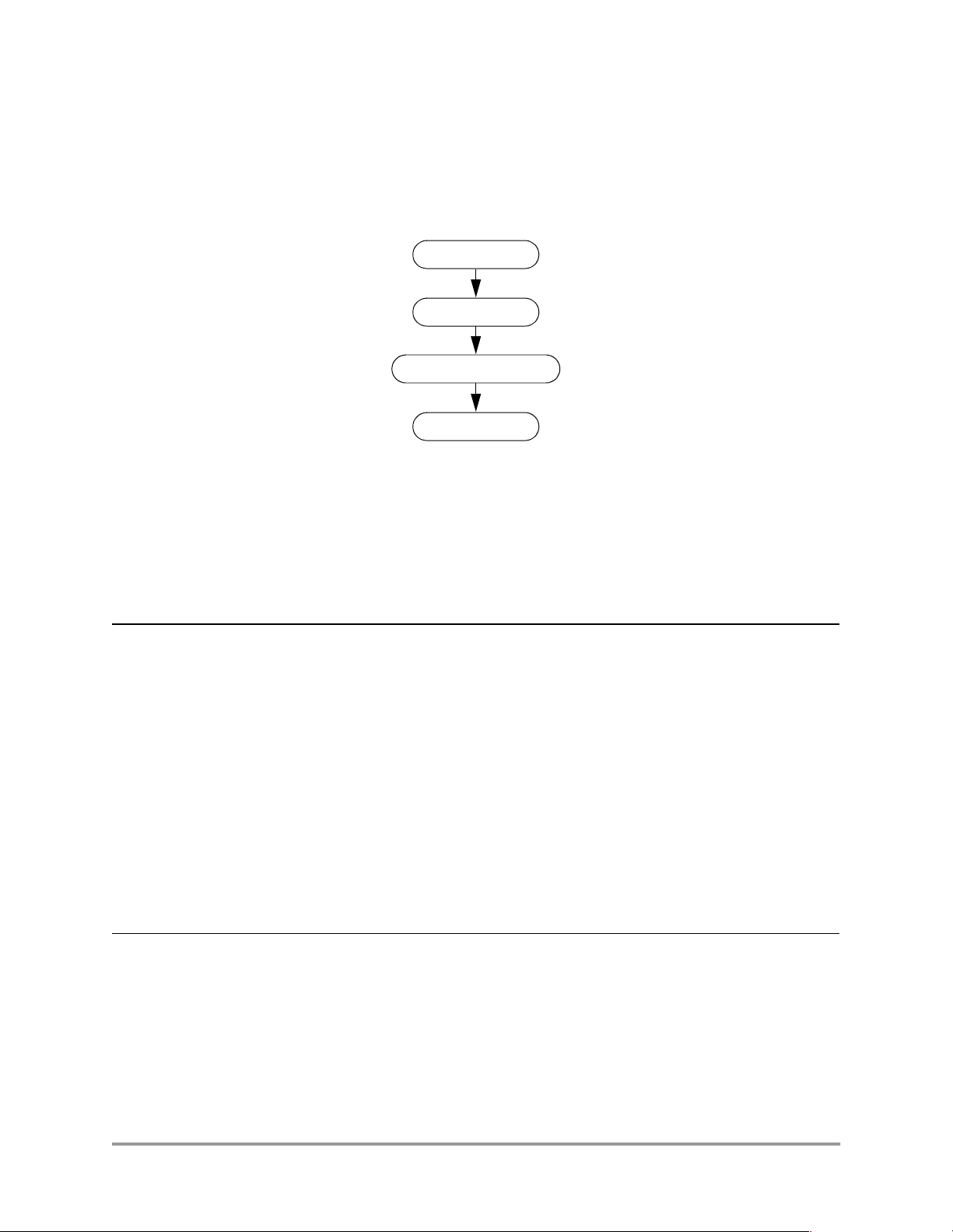
This section describes the operations necessary to initialize, start, and stop the stopwatch timer within an
application. The sequence of operations is shown in Figure 1. Additionally, this section presents the
conversion of cyc les t o ac tual time and puts all t he application cod e t oge the r. Finally, this sect ion explains
how to adapt the stopwatch timer code to other SC140-based devices.
Initialize Stopwatch
Enable Stopwatch
Sequence Instructions
to be Timed
Disable Stopwatch
Figure 1. Sequence of Operations
3.1 Initializing the Stopwatch Timer
The C code to set up the stopwatch timer is shown in Code 1.
Code 1. Event Detector Setup Code
/*
* Header file contains defin itions of EOnCE memor y-mapped register add resses,
* and definition of the WRIT E_IOREG() macro.
*/
#include “EOnCE_registers.h”
static volatile long EOnCE_s topwatch_timer_flag; /*Global du mmby variable*/
void EOnCE_stopwatch_timer_i nit()
{
WRITE_IOREG(EDCA1_REFA,(long )&EOnCE_stopwatch_tim er_flag);
WRITE_IOREG(EDCA1_REFB,(long )&EOnCE_stopwatch_tim er_flag);
WRITE_IOREG(EDCA1_MASK,MAX_3 2_BIT);
WRITE_IOREG(EDCA1_CTRL,0x3f0 6);
}
/* Address to snoop for on X ABA */
/* Address to snoop for on X ABB */
/* No masking is performed i n address comparison */
/* Detect writes on both XAB A and XABB */
The header file “EOnCE_registers.h” contains the macro definitions, such as EDCA1_MASK, which
provides each of the Enhanced OnCE memory-mapped register’s corresponding memory address.
This header file also defines the C macros: READ_IOREG() and WRITE_IOREG(). These macros
simplify the read and write operations on memory-mapped registers.
Setting Up the Stopwatch Timer Within an Application 3
Page 8
Initializing the stopwatch timer consists of setting up the Address Event Detection Channel (EDCA). The
role of EDCA in the stopwatch timer implementation is to trigger the commencement of the cycle
countdown. The Enhanced OnCE supports six EDCAs. The implementation presented in this application
note uses EDCA1, though this choice is arbitrary.
Set up of the EDCA requires initializing the following four registers:
• The 32-bit EDCA reference value register A (EDCA1_REFA).
• The 32-bit EDCA reference value register B (EDCA1_REFB).
• The 32-bit EDCA mask register (EDCA1_MASK).
• The 16-bit EDCA control register (EDCA1_CTRL).
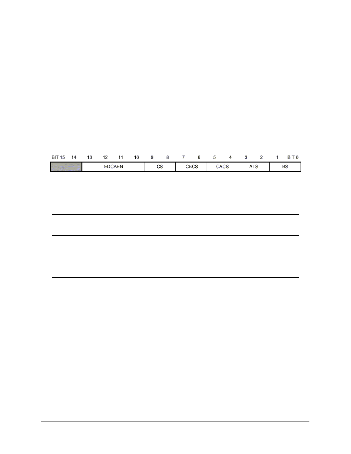
3.1.1 Event Detecto r Control
The register, EDCA1_CTRL, c ontrols the beha vior of the EDCA. The fields of the EDCA1_ CTRL regist er
are shown in Figure 2.
Figure 2. EDCA Control Register (EDCA1_CTRL)
Table 1 describes the settings of these fields in the stopwatch timer implementation.
Table 1. EDCA_CTRL Settings
Field
EDCAEN 1111 This channel is enabled
CS 11 Trigger event if address matches either comparator A or comparator B
CBCS 00 An “address match” is detected when sampled bus value equals value in
CACS 00 An “address match” is detected when sampled bus value equals value in
ATS 01 Detect write access only
BS 10 The sampled buses are XABA and XABB
Setting
(binary value)
Description
EDCA_REFB
EDCA_REFA
The EDCA becomes enabled as soon as th ese val ues are written into the control register. The EDCA stays
enabled for the duration of the program execution to enable repeated use of the stopwatch timer.
3.1.2 Address Comparison Setup
The purpose of the address comparison in the EDCA is to detect writes to the stopwatch timer flag
variable. Because writes may take place on either of the two data m emory buses, both registers,
EDCA1_REFA and EDCA1_REFB, are set up to contain the address of the stopwatch timer flag variable.
The register EDCA1_MASK allows masking of address bits when comparing the sampled address with
those in the EDCA1_REFA and EDCA1_REFB registers. In the implementat ion of the sto pwatch timer all
4 Using the SC140 Enhanced OnCE Stopwatch Timer
Page 9
32-bits of the flag variable’s address are used. Thus, EDCA1_MASK is se t to 0xffffffff, meaning all
address bits will be compared.
3.2 Starting the Stopwatch Timer
The C code to start the stopwatch timer is shown in Code 2.
Code 2. C Code to Start the Stopwatch Timer
#include “EOnCE_registers.h”
void EOnCE_stopwatch_timer_s tart()
{
WRITE_IOREG(ECNT_VAL,MAX _32_BIT); /* Countdown will start at ( 2**32)-1 */
WRITE_IOREG(ECNT_EXT,0); /* Extension will count up f rom zero */
WRITE_IOREG(ECNT_CTRL,0x 12c);
EOnCE_stopwatch_timer_fl ag = 0;
}
Before triggering the stopwatch ti mer, it is necessary to initialize the counter registers. Ini tializing the
event counter requires set up of the following three 32-bit registers:
• Event counter value register (ECNT_VAL)
• Extension counter value register (ECNT_EXT)
/* Counting will be triggere d by detection on EDC A1 */
/* This write to the flag tr iggers the counter */
• Event counter control register (ECNT_CTRL)
Once these initializations are complete, the C code triggers the stopwatch timer and cycle counting
commences.
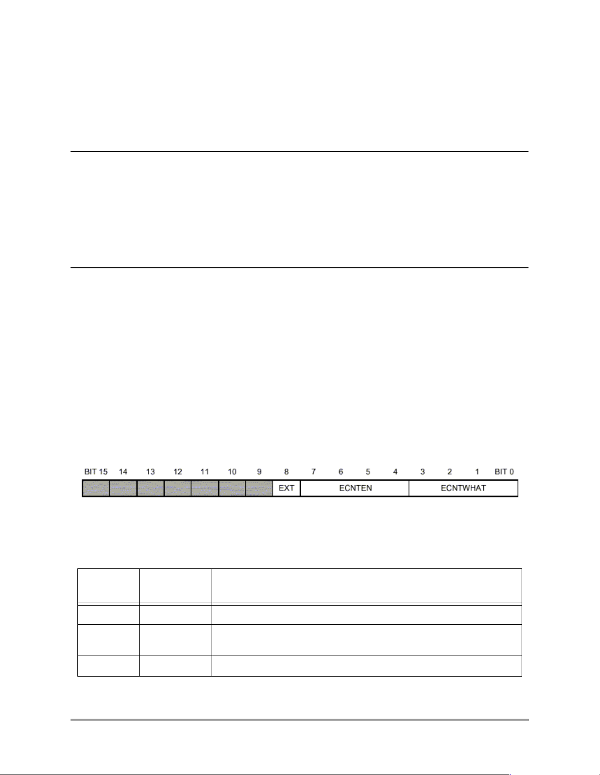
3.2.1 Event Counter Control
This section desc ribes the i niti aliza tion o f the even t count er re gist ers. The re giste r, ECNT_C TRL, contr ols
the behavior of the event counter. The fields of the ECNT_CTRL register are shown in Figure 3.
Figure 3. Event Counter Control Register (ECNT_CTRL)
Table 2 describes the settings of these fields in the stopwatch timer implementation.
Table 2. ECNT_CTRL Settings
Field
EXT 1 Event counter operates as a 64-bit counter
ECNTEN 0010 The event counter is disab led, and will b e enabled whe n an event is detected
Setting
(binary value)
Description
by EDCA1
ECNTWHAT 1100 The counter will advance on each core clock cycle
Setting Up the Stopwatch Timer Within an Application 5
Page 10

3.2.2 Counter Registers
ECNT_VAL is a countdown counter, and ECNT_EXT is a countup counter. ECNT_VAL is decremented
on each occurrence of an event, as specified in the control register. ECNT_EXT is incremented each time
there is an underflow in ECNT_VAL.
For maximum cycle counting capacity, the stopwatch timer implementation initializes ECNT_VAL to the
largest possible value which is 4294967295, or 0xffffffff.
ECNT_EXT is initialized to zero.
3.3 Stopping the Stopwatch Timer
The C code to stop the stopwatch timer is shown in Code 3.
Code 3. C Code to Stop the Stopwatch Timer
#include “EOnCE_registers.h”
void EOnCE_stopwatch_timer_s top(unsigned long *cl ock_ext, unsigned lon g *clock_val)
{
WRITE_IOREG(ECNT_CTRL,0) ; /* Disable event counter */
READ_IOREG(ECNT_VAL,*clo ck_val); /* Save ECN T_VAL in program vari able */
READ_IOREG(ECNT_EXT,*clo ck_ext); /* Save ECN T_EXT in program vari able */
*clock_val = (MAX_32_BIT -*clock_val); /* Adj ust for countdown */
}
To stop the stopwatch ti mer, the ECNT_CTRL register is set to zero. After stopping the stopwatch timer,
the routine copies the values of ECNT_VAL and ECNT_EXT registers into program variables. This
allows putting the stopwatch timer into use again without losing the result of the previous measurement.
Because ECNT_VAL contains the result of a countdown process, the routine converts that result into the
actual number of cycles elapsed by subtracting the ECNT_VAL from the value to which it was initialized,
specifically, 4294967295.
3.4 Converting Cycles to Actual Time
The stopwatch timer measures durations in units of core clock cycles. Most often the units of interest are
units of absolute time, such as milliseconds or microseconds.
Conversion from core clock cycles, as measured by the event counter registers, to milliseconds is
computed in Equation 1.
1000
Time ms() EXT 0xffffffff× VAL+()
In this equation, EXT is the value in ECNT_EXT, VAL is the value in ECNT_VAL, and Clock Speed is
measured in hertz.
Code 4 on page -7 shows the C code for clock-cycle-to-time conversion.
The C code depends on s etting the value of t he consta nt CLOCK_SPEED in EOnCE_s topwatch.c to match
the clock speed as set in the PLL.
------------------------------- -
×=
ClockSpeed
Eqn. 1
The conversion routine distinguishes between three different output units: seconds, milliseconds, and
microseconds. Handling each unit separately allows the computations to be performed using integer
arithmetic without loss of accuracy.
6 Using the SC140 Enhanced OnCE Stopwatch Timer
Page 11

Code 4. C Code for Clock-Cycle-to-Time Conversion
typedef enum { EONCE_SECOND, EONCE_MILLISECOND, E ONCE_MICROSECOND } tu nit;
unsigned long Convert_clock2 time(unsigned long cl ock_ext, unsigned lon g clock_val,
short option)
{
unsigned long result;
switch(option)
{
case EONCE_SECOND:
result= clock_ex t*MAX_32_BIT/CLOCK_SP EED + clock_val/CLOCK _SPEED;
break;
case EONCE_MILLISECO ND:
result= clock_ex t*MAX_32_BIT/(CLOCK_S PEED/1000)
+ clock_ val/(CLOCK_SPEED/1000 );
break;
case EONCE_MICROSECO ND:
result= clock_ex t*MAX_32_BIT/(CLOCK_S PEED/1000000)
+ clock_ val/(CLOCK_SPEED/1000 000);
break;
default: result=0; /* error condition */
break;
}
return result;
}
3.5 Putting it All Together
Code 5 depicts the use of the stopwatch timer using the routines that have been described so far.
Code 5. Use of Stopwatch Timer Functions
long clock_ext,clock_val,clo ck_cycle,time_sec;
EOnCE_stopwatch_timer_init() ; /* Execute once pe r program execution * /
...
EOnCE_stopwatch_timer_start( );
/*
* Code whose execution time is measured goes her e
*/
EOnCE_stopwatch_timer_stop(& clock_ext, &clock_val);
...
time_sec = Convert_clock2tim e(clock_ext, clock_va l, EONCE_SECOND);
...
...
EOnCE_stopwatch_timer_start( );
/*
* Code whose execution time is measured goes her e
*/
EOnCE_stopwatch_timer_stop(& clock_ext, &clock_val);
...
time_sec = Convert_clock2tim e(clock_ext, clock_va l, EONCE_SECOND);
...
The calls to the stop watch timer functions can be made from di fferent loc ations in t he applica tion code, no t
necessarily from within one subroutine. The
EOnCE_stopwatch_timer_stop( ) can be called more th an once to measure the time consumed in diff erent
EOnCE_stopwatch_timer_start() and
modules as desired.
Setting Up the Stopwatch Timer Within an Application 7
Page 12

3.6 Adapting Stopwatch Timer Code to Other SC140
Devices
The stopwatch timer implementation controls the Enhanced OnCE by writing to its memory-mapped
registers. The addresses of these registers are determined in the memory map of the device in which the
SC140 core is embedded. The offset between the base address of the memory-mapped peripherals and the
addresses of the Enhanced OnCE registers is the same across SC140-based devices.
Therefore, when adapting the stopwatch timer code for a specific device it suffices to set the value of
REG_BASE_ADDRESS in the header file “EOnCE_registers.h.” In the Software Development Pl atform
(SDP), the base register of Enhanced OnCE is 0x00effe00. Consult the user manual of the specific device
for the value to set this C macro.
4 Setting Up the Stopwatch Timer Within the
Debugger
The preceeding secti on describe d a technique that requi res instr umenting, or modi fying, the s ource code of
the application being measured. Occasionally developers are faced with a situation where instrumentation
of the code is not possible. For example, the code might be available in object form only.
In such cases it is possible to measure execution times by setting up the stopwatch timer within the
Metrowerks Code Warrior SC140 debugger. This section explains this set up.
4.1 Initializing the Stopwatch Timer
The technique described in Section 3 triggered the stopwatch timer by detecting a write to the stopwatch
timer flag variable. When t he st opwat ch timer is set up within the debugger, the triggering event is chosen
to be the execution of the first instruction in the measured code. Program code disassembly is used to
obtain the address of this first instruction.
NOTE:
In the following descriptions of selecting options in the debugger
windows, the > character separates each command in the menu hierarchy.
For example, EOnCE > EOnCE Configurator > EDCA1 lists the
hierarchy to be f ollowed to select the EDCA1. In this exampl e, one woul d
highlight EOnCE in menu bar, then highlight EOnCE Configurator, and
finally, choose the EDCA1 tab.
4.1.1 Setting Up the Event Detector
The procedure to set up the stopwatch timer is described in this section. To set up the event detector, find
the starting address of the measured function or sequence of instructions, as follows:
1. Choose Project > Debug.
2. In the debugger window, choose “mixed”.
The starting address can be found in mixed mode, as shown in Figure 4 on page -9.
8 Using the SC140 Enhanced OnCE Stopwatch Timer
Page 13

Figure 4. Finding the Starting Address in the Debugger
After finding the starting address, the event detector can be setup. The procedures are outlined in these
steps:
1. Choose EOnCE > EOnCE Configurator > EDCA1.
2. Click PC in the “Bus Selection” box.
3. Enter the address of the first instruction in the measured code into the “Comparator A Hex
32-bits” box.
4. Click Enable in the “Enabled after Event On” box.
Figure 5 on page -10 shows the event detection settings after perf orming these steps. For more detailed
information in Enhanced OnCE configuration in Code Warrior tools, refe r to [3].
Setting Up the Stopwatch Timer Within the Debugger 9
Page 14

Figure 5. Event Detection Settings
4.1.2 Setting Up the Event Counter
The event counter is conf igu re d to th e sam e mode as described in Section 3.2.1, “Event Counter Control,”
on page -5, except this time the configuration is made using the debugger windows:
1. Choose EOnCE > EOnCE Configurator > Counter.
2. Click Core Clock in the “What to count” box.
3. Click EDCA1 in the “Enable after Even On” box.
4. Type “0xffffffff” in the “Event Counter Value (Hex 32 bits)” box.
5. Check the box in the left side of “Extension Counter Value (Hex 32 bits)”.
The result of this procedure is shown in Figure 6 on page -11.
10 Using the SC140 Enhanced OnCE Stopwatch Timer
Page 15

Figure 6. Event Counter Settings
4.2 Stopping the Stopwatch Timer
Stopping the stopwatch timer is achieved by ha lting execu tion of the app licatio n at a breakpoin t. Set up the
breakpoint at the point in the application at which timing should stop to achieve the desired affect.
After the breakpoint is in place, the debugger can be instructed to run the application.
When execution of the app licatio n reaches t he breakpoi nt, the valu e of the stop watch timer counters ca n be
retrieved by opening the EOnCE > EOnCE Configurator > Counter dialog box. Figure 7 on page -12
shows an example of an event counter dialog box after the debugger halt at the breakpoint. Because the
countdown counter is initialized to maximum value (0xffffffff), the difference between maximum value
and the value in the “Event Counter Value” column yields the real SC140 clock counts. To convert the
values of the real SC140 clock counts to absolute time use the computation described in Section 3.4,
“Converting Cycles to Actual Time,” on page -6.
After the debugger s top s at the breakpoint, the counter, which is setup in sleep mode and is enabled by the
events at the first instruction of the measured code, is now in enabled mode and continues to count (see
“Enabled after Event on” column in Figure 7 on page -12). However, continued counting is irre levant
because the SC140 clock count has been achieved.
Setting Up the Stopwatch Timer Within the Debugger 11
Page 16

Figure 7. Event Counter Dialog Box When Debugger Halts at Breakpoint
5 Setting Up the System Clock Speed
Every SC140-based device contains a Phase Lock Loop (PLL) block, which cont rols the operating
frequency of the device. The frequency of the device is governed by the frequency control bits in the PLL
control register, as defined in Equation 2.
Fext MFI
Fdevice
In this equation:
• MFI (multiplication factor integer), MFN (multi plication factor numerator), MFD (multiplication
factor denominator), and PODF (post division factor) are defined in the PCTL1 register.
• PDF (pre-division factor) is defined in the PCTL0 register.
• Fext is external input frequency to the chip at the EXTAL pin.
• Fdevice is the operati ng frequency of the device.
The range of values of these terms are descri be in [1] .
Figure 8 and Figure 9 on page -13 illustrate the PLL control regist ers; PCTL0 and PCTL1, respectively.
-------------------------------------------------------
=
×
PODF PDF×
+
MFN
------------MFD
Eqn. 2
12 Using the SC140 Enhanced OnCE Stopwatch Timer
Page 17

Figure 8. Programming Model of PCTL0
Figure 9. Programming Model of PCTL1
5.1 Setting Up the PLL in Software
The clock frequency of the SC140 can be set up either in software or in hardware. This section describes
how to set the SC140 in th e So ftware Develo pment Pl atfor m (SDP) to op erate at 30 0 MHz using these two
alternatives. The C code to set up the PLL to 300 MHz is shown in Code 6.
Code 6. C Code to Set Up the PLL to 300 MHz
#include “EOnCE_registers.h”
void PLL_setup_300MHz()
{
}
asm("move.l #$80030003,PCTL0 ");
asm("move.l #$00010000,PCTL1 ");
To set up the SC140 for operation at 300 MHz, the registers PCTL0 and PCTL1 should be set to the val ues
0x80030003 and 0x00010000, respectively. These settings are explained in Table 3.
Table 3. Settings of PCTL0 and PCTL1
Field
PCTL0.PEN 1 PLL enabled. The internal clocks are deriv ed from the PLL output
PCTL0.RCP 0 PLL locks with respect to the positive edge of the reference clock
PCTL0.MFN 000000000 MFN = 0
PCTL0.MFI 1100 MFI = 24
PCTL0.MFD 000000000 MDF = 1
PCTL0.PD 0011 PD = 4
PCTL1.COE 1 Clock out pin receives output
PCTL1.PODF 0 PODF = 1
Setting
(binary value)
Description
Setting Up the System Clock Speed 13
Page 18

With these configurations, the Fchip is calculated as expressed in Equation 3.
50MHz 24
Fchip
The PLL should be configured so that the resulting PLL output frequency is in the range specified in the
device’s technical data sheet.
----------------------------------------------
×
41×
0
-- -
+
1
300Mhz==
Eqn. 3
5.2 Setting Up the PLL in Hardware
During the assertion of hardware reset, the value of all the PLL hardware configurations pins are sampled
into the clock control registers (PCTL0 and PCTL1). Thus, it is possible to set up the core frequency at
reset by configuring the jumpers on the SDP board.
To set up the PLL for operation at 300 MHz, the jumpers for PLLEN, PDF1, PDF0, MFI3 and MFI2
should be removed (thereby causing these bits to be asserted).
For more detail information jumper configuration of SDP, refers to [2].
6 Verifying Correct Setup
The previous sections described how to set up the Enhanced OnCE stopwatch timer and the DSP clock
speed. This section de sc ri bes tec hniques to verify that the system is set up corre ctl y and that the Enhanced
OnCE stopwatch timer measurements are reasona ble as descr ibed in Sect ion 3, “Setting Up the Stopwatch
Timer Within an Application,” on page -3.
The verification process is based on measuring a specified time period, while also creating an external
behavior (turning on and off an LED) that can be measured independently by a “wall clock” (that is; an
independent stopwatch, such as; an oscilloscope).
6.1 Using the LED on the SDP
The implementation described in this section is based on the configuration of the Software Development
Platform (SDP). In SDP, each of EE1 pins of the Enhanced OnCE is connected to an LED .
The following implementation is based on the ability to program the Enhanced OnCE to toggle the output
value on its pins whenever an event is detected by one of the Enhanced OnCE event detection channels.
The implementation b el ow to ggl es the output value on the pin EE1 whenever the s top wat ch t imer s tar t s or
stops running. This capability requires just a small enhancement to the stopwatch timer software that is
presented in Code 6 on page -13.
6.1.1 Setting Up EE1
The functionality of the Enhanced OnCE pins is controlled through the Enhanced OnCE pins control
register (EE_CTRL). Figure 10 displays the structure of this register.
Figure 10. EE Pins Control Register (EE_CTRL)
14 Using the SC140 Enhanced OnCE Stopwatch Timer
Page 19

In EE_CTRL, the EE1DEF field is set to 00, which signifies output signal when detected by EDCA1. The
remaining fields in EE_CTRL are irrelevant because they are not used.
Code 7 shows the setup code for EE control registers.
Code 7. EOnCE_LED_init()
void EOnCE_LED_init()
{
}
*((long *)EE_CTRL) &= ~(3<<2 ); /* Toggle EE1 whe n event1 happens */
6.1.2 Toggling EE1
The initialization previously discussed the set up of EE1 to toggle each time an event is detected by
EDCA1. The same channel is also used to trigger the stopwatch timer to count. Therefore, all that remains
is to create an EDCA1 event when the stopwatch timer stops. This is achieved by writing to the Enhanced
OnCE stopwatch timer flag variable.
Caution must be taken to perform this write only after execution of
Code 8. Turn LED Off
void EOnCE_LED_off(){
EOnCE_stopwatch_timer_fl ag = 0; /* Create an EDCA1 event */
}
EOnCE_stopwatch_timer_stop().
6.2 Testing the Stopwatch Timer
The program depicted in Code 9 on page -16 sets up the stopwatch timer and then measures the time it
takes to execute two loops whose duration is built into the program.
The measured code sequences are constructed to take 10 seconds and 7.5 seconds, respectively. These
durations are constructed by having the code sample the Enhanced OnCE counter and loop until the
expected number of clock cycles have passed.
It is recommended to try this code prior to measuring the target application, as a means of verifying correct
setup of the system. If the times measured are not correct, it is recommended to check the PLL setup and
the values of the clock speed and the memory-mapped register base (as set in the header files).
If the SC140 compiler beta 1.0 V is used, COMPILER_BETA_1_BUG must be defined to make the code
run correctly. In the macro WRITE_IO(REG,VAL) or READ_IO(REG,VAL), REG is deemed as 16-bit
even though it is 32-bit in macro definition. It is fixed by explicitly declaring a long variable if
COMPILER_BETA_1_BUG is defined.
Verifying Correct Setup 15
Page 20

Code 9. Testing Code
#include <stdio .h>
#include "EOnCE _stopwatc h.h"
#ifdef COMPILER_BE TA_1_BUG
extern long ECNT_VAL;
#else
#include "EOnCE _register s.h"
#endif
void PLL_setup_ 300MHz()
{
asm("move.l #$800300 03,PCT L0");
asm("move.l #$000100 00,PCT L1");
}
void main(){
unsigned long clock_ext,cloc k_val,clock_ cycle,cy cle_req;
unsigned long time_sec;
extern unsi gned long CLOCK _SPEED;
PLL_setup_3 00MHz();
EOnCE_stopw atch_time r_init (); /* Se tup to ev ent d etector 1 for any write to
du mmy varia ble. Setup EOn CE event count er
to count if even t 1 happe ns */
EOnCE_LED_i nit(); /* Se tup LED t o tog gle in de tection of
ev ent 1 */
cycle_req = CLOCK_SP EED*10 ; /* Ca lculate t otal clock cyc les requ ired
by 10 sec * /
EOnCE_stopw atch_time r_star t(); /* Ev ent 1 hap pens, counter & LED on */
do {
READ_IO REG(ECNT_ VAL,cl ock_cycl e); /* Re ad bit 31 -0 co unter val ue */
clock_c ycle = MA X_32_B IT - clo ck_cycle; /* Mi nus max v alue due to co unt down */
} while (cl ock_cycle <= cy cle_req) ;
EOnCE_stopw atch_time r_stop (&clock_ ext, &clo ck_va l); /* S top t imer, ret urn bit 63-0
EOnCE_LED_o ff(); /* L ED off */
time_sec = Convert_clock2tim e(clock_ext, clock_val, EONCE_SECOND) ;
printf("dur ation = % u sec\ n", time _sec);
counter value */
cycle_req = CLOCK_SP EED*7. 5; / * Cal culate to tal c lock cycl es requi red
by 7.5 sec */
EOnCE_stopw atch_time r_star t(); / * Eve nt 1 happ ens, counter & LED on */
do {
READ_IO REG(ECNT_ VAL,cl ock_cycl e); /* Re ad bit 31 -0 co unter val ue */
clock_c ycle = MA X_32_B IT - clo ck_cycle; /* Mi nus max v alue due to co unt down */
} while (cl ock_cycle <= cy cle_req) ;
EOnCE_stopw atch_time r_stop (&clock_ ext, &clo ck_va l); /* S top t imer, ret urn bit 63-0
EOnCE_LED_o ff(); /* LE D off */
time_sec = Convert_clock2tim e(clock_ext, clock_val, EONCE_MILLISE COND);
printf("dur ation = % u ms\n ", time_ sec);
return;
}
counter value */
16 Using the SC140 Enhanced OnCE Stopwatch Timer
Page 21

7 Conclusion
This application note presented two techniques to measure the speed of execution of software running on
an SC140 device, using the SC140 Enhanced OnCE. The first technique requires instrumenting the
application code wit h c alls to st opwatch timer r outin es. The sec ond tec hnique con trols the s topwatc h timer
within the Metrowerks Code Warrier debugger.
In addition, examples were provided in this application note to demonstrate setting up the SC140 Phase
Lock Loop, and software control of the LED available on the Software Development Platform.
8 References
[1] StarCore SC140 DSP Core Reference Manual (order number MNSC140CORE/D),
Motorola Inc., 2000.
[2] StarCore 140 Software Development Platform, Hardware Reference Manual
(order number SC140SDPRM/D), Motorola Inc., 1999.
[3] Code Warrior Targeting StarCore (Beta 1.0 Release), Metrowerks Corp., 1993.
Conclusion 17
Page 22

18 Using the SC140 Enhanced OnCE Stopwatch Timer
Page 23

Appendix A
Complete Example of Profiling
A complete example of profiling using the Enhanced OnCE stopwatch timer in the SC140 platform is
presented in this appendix.
Code A-1. EOnCE_stopwatch.h
typedef enum { EONCE_SEC OND, E ONCE_MIL LISECOND, EONC E_MICROSE COND } tunit;
#define READ_IO REG(reg,v al) va l = *((v olatile l ong * )reg)
#define WRITE_I OREG(reg, val) * ((volati le long * )reg) = val
#define MAX_32_ BIT 0xfff fffff
void EOnCE_stop watch_tim er_ini t();
void EOnCE_stop watch_tim er_sta rt();
void EOnCE_stop watch_tim er_sto p(unsign ed long * clock _ext, uns igned long *cl ock_val) ;
void EOnCE_LED_ init();
void EOnCE_LED_ off();
unsigned long Convert _clock2time (unsigned long clock_ext, uns igned long clock_ val, short opt ion);
Complete Example of Profiling A-1
Page 24

Code A-2. EOnCE_registers.h
/* EOnCE regi sters */
#define EXCP_TA BLE 0x700 0
#define REG_BAS E_ADDRESS 0x00e ffe00 /* EOnCE Status r egist er */
#ifdef COMPILER_BE TA_1_BUG
long EE_CTRL = REG_BASE _ADDRESS+ 0x18; /* EOnCE EE p ins Contr ol regis ter */
long EDCA1_CTR L = REG_BASE _ADDRESS+ 0x44; /* EOnCE EDCA #1 Contr ol regis ter */
long EDCA1_REF A = REG_BASE _ADDRESS+ 0x64; /* EOnCE EDCA #1 Refer ence Val ue A * /
long EDCA1_REF B = REG_BASE _ADDRESS+ 0x84; /* EOnCE EDCA #1 Refer ence Val ue B * /
long EDCA1_MAS K = REG_BASE _ADDRESS+ 0xc4; /* EOnCE EDCA #1 Mask Register */
long ECNT_CTRL = REG_BASE _ADDRESS+ 0x100 ; /* EOnC E Cou nter Cont rol regi ster * /
long ECNT_VAL = REG_BASE _ADDRESS+ 0x104 ; /* EOnC E Cou nter Valu e regist er */
long ECNT_EXT = REG_BASE _ADDRESS+ 0x108 ; /* EOnC E Ext ension Co unter Va lue */
#else
#define EMCR REG_BA SE_ADDRES S+0x4 /* EOnCE Moni tor and C ontrol r egiste r */
#define ERCV REG_BA SE_ADDRES S+0x8 /* EOnCE Rece ive regis ter */
#define ETRSMT 0 REG_BA SE_ADDRES S+0x1 0 /* EOnC E Rec eive regi ster */
#define ETRSMT 1 REG_BA SE_ADDRES S+0x1 4 /* EOnC E Rec eive regi ster */
#define EE_CTR L REG_BA SE_ADDRES S+0x1 8 /* EOnC E EE pins Cont rol regi ster * /
#define PC_EX REG_BA SE_ADDRES S+0x1 c /* EOnC E Exc eption PC registe r */
#define EDCA0_ CTRL REG_BA SE_ADDRES S+0x4 0 /* EOnC E EDC A #0 Cont rol regi ster * /
#define EDCA1_ CTRL REG_BA SE_ADDRES S+0x4 4 /* EOnC E EDC A #1 Cont rol regi ster * /
#define EDCA2_ CTRL REG_BA SE_ADDRES S+0x4 8 /* EOnC E EDC A #2 Cont rol regi ster * /
#define EDCA3_ CTRL REG_BA SE_ADDRES S+0x4 c /* EOnC E EDC A #3 Cont rol regi ster * /
#define EDCA4_ CTRL REG_BA SE_ADDRES S+0x5 0 /* EOnC E EDC A #4 Cont rol regi ster * /
#define EDCA5_ CTRL REG_BA SE_ADDRES S+0x5 4 /* EOnC E EDC A #5 Cont rol regi ster * /
#define EDCA0_ REFA REG_BA SE_ADDRES S+0x6 0 /* EOnC E EDC A #0 Refe rence Va lue A */
#define EDCA1_ REFA REG_BA SE_ADDRES S+0x6 4 /* EOnC E EDC A #1 Refe rence Va lue A */
#define EDCA2_ REFA REG_BA SE_ADDRES S+0x6 8 /* EOnC E EDC A #2 Refe rence Va lue A */
#define EDCA3_ REFA REG_BA SE_ADDRES S+0x6 c /* EOnC E EDC A #3 Refe rence Va lue A */
#define EDCA4_ REFA REG_BA SE_ADDRES S+0x7 0 /* EOnC E EDC A #4 Refe rence Va lue A */
#define EDCA5_ REFA REG_BA SE_ADDRES S+0x7 4 /* EOnC E EDC A #5 Refe rence Va lue A */
#define EDCA0_ REFB REG_BA SE_ADDRES S+0x8 0 /* EOnC E EDC A #0 Refe rence Va lue B */
#define EDCA1_ REFB REG_BA SE_ADDRES S+0x8 4 /* EOnC E EDC A #1 Refe rence Va lue B */
#define EDCA2_ REFB REG_BA SE_ADDRES S+0x8 8 /* EOnC E EDC A #2 Refe rence Va lue B */
#define EDCA3_ REFB REG_BA SE_ADDRES S+0x8 c /* EOnC E EDC A #3 Refe rence Va lue B */
#define EDCA4_ REFB REG_BA SE_ADDRES S+0x9 0 /* EOnC E EDC A #4 Refe rence Va lue B */
#define EDCA5_ REFB REG_BA SE_ADDRES S+0x9 4 /* EOn CE ED CA #5 Ref erence V alue B */
#define EDCA0_ MASK REG_BA SE_ADDRES S+0xc 0 /* EOn CE ED CA #0 Mas k Regist er */
#define EDCA1_ MASK REG_BA SE_ADDRES S+0xc 4 /* EOn CE ED CA #1 Mas k Regist er */
#define EDCA2_ MASK REG_BA SE_ADDRES S+0xc 8 /* EOn CE ED CA #2 Mas k Regist er */
#define EDCA3_ MASK REG_BA SE_ADDRES S+0xc c /* EOn CE ED CA #3 Mas k Regist er */
#define EDCA4_ MASK REG_BA SE_ADDRES S+0xd 0 /* EOn CE ED CA #4 Mas k Regist er */
#define EDCA5_ MASK REG_BA SE_ADDRES S+0xd 4 /* EOn CE ED CA #5 Mas k Regist er */
#define EDCD_C TRL REG_BA SE_ADDRES S+0xe 0 /* EOn CE ED CD Contro l regist er */
#define EDCD_R EF REG_BA SE_ADDRES S+0xe 4 /* EOn CE ED CD Refere nce Valu e */
#define EDCD_M ASK REG_BA SE_ADDRES S+0xe 8 /* EOn CE ED CD Mask r egister */
#define ECNT_C TRL REG_BA SE_ADDRES S+0x1 00 /* EO nCE C ounter Co ntrol re gister */
#define ECNT_V AL REG_BA SE_ADDRES S+0x1 04 /* EO nCE C ounter Va lue regi ster * /
#define ECNT_E XT REG_BA SE_ADDRES S+0x1 08 /* EO nCE E xtension Counter Value */
#define ESEL_C TRL REG_BA SE_ADDRES S+0x1 20 /* EO nCE S elector C ontrol r egiste r */
#define ESEL_D M REG_BA SE_ADDRES S+0x1 24 /* EO nCE S elector D M Mask * /
#define ESEL_D I REG_BA SE_ADDRES S+0x1 28 /* EO nCE S elector D I Mask * /
#define ESEL_R ST REG_BA SE_ADDRES S+0x1 2c /* EO nCE S elector R ST Mask */
#define ESEL_E TB REG_BA SE_ADDRES S+0x1 30 /* EO nCE S elector E TB Mask */
#define ESEL_D TB REG_BA SE_ADDRES S+0x1 34 /* EO nCE S elector D TB Mask */
#define TB_CTR L REG_BA SE_ADDRES S+0x1 40 /* EO nCE T race Buff er Contr ol reg ister */
#define TB_RD REG_BA SE_ADDRES S+0x1 44 /* EO nCE T race Buff er Read Pointe r */
#define TB_WR REG_BA SE_ADDRES S+0x1 48 /* EO nCE T race Buff er Write Point er */
#define TB_BUF F REG_BA SE_ADDRES S+0x1 4c /* EO nCE T race Buff er */
#define TRAP_E XCP EXCP_T ABLE /* trap instructi on ex ception * /
#define ILL_EXCP EXCP_TABLE+0x80 /* illeg al set or illegal instruc tion exception */
#define DBG_EX CP EXCP_T ABLE+0xc0 /* debug exc eptio n (eonce) */
#define OVFL_E XCP EXCP_T ABLE+0x10 0 /* overflow exce ption */
#define AUTO_N MI_EXCP EXCP_T ABLE+0x18 0 /* default nmi e xception vector * /
#define AUTO_E XT_EXCP EXCP_T ABLE+0x1c 0 /* default exter nal excep tion */
#define NMI_EX CP EXCP_T ABLE+0x28 0 /* nmi exce ption vector ( arbitrar y addr ess) */
#define EXT_EX CP EXCP_T ABLE+0x2c 0 /* external exce ption (a rbitrary addre ss) */
#endif
A-2 Using the SC140 Enhanced OnCE Stopwatch Timer
Page 25

Code A-3. EOnCE_stopwatch.c
/*
* Header file c ontains d efinit ions of EOnCE mem ory-m apped reg ister addresse s,
* and definitio n of the WRITE_ IOREG() macro.
*/
#include "EOnCE _register s.h"
#include "EOnCE _stopwatc h.h"
unsigned long C LOCK_SPEE D = 30 0000000;
static volatile long EOn CE_stopwatc h_timer_f lag; /*Global dummby vari able*/
void EOnCE_stop watch_tim er_ini t()
{
}
void EOnCE_LED_ init()
{
}
void EOnCE_stop watch_tim er_sta rt()
{
WRITE_IOREG (ECNT_VAL ,MAX_3 2_BIT); /* Countdo wn will start at (2**32 )-1 */
WRITE_IOREG (ECNT_EXT ,0); /* Exte nsion wil l count up fro m zero */
WRITE_IOREG (ECNT_CTR L,0x12 c);
EOnCE_stopw atch_time r_flag = 0;
}
void EOnCE_stop watch_tim er_sto p(unsign ed long * clock _ext, uns igned long *cl ock_val)
{
WRITE_IOREG (ECNT_CTR L,0); /* Disable event counter */
READ_IOREG(ECNT_VAL,*cl ock_val); /* Save ECNT _VAL in program var iable */
READ_IOREG(ECNT_EXT,*cl ock_ext); /* Save ECNT _EXT in program var iable */
*clock_val = (MAX_32 _BIT-* clock_va l); / * Adjust for c ountdown */
}
void EOnCE_LED_ off()
{
EOnCE_stopw atch_time r_flag = 0; /* Create an E DCA1 even t */
}
unsigned long Convert _clock2time (unsigned long clock_ext, uns igned long clock_ val, short opt ion)
{
unsigned long result;
switch(opti on)
{
case EO NCE_SECON D:
res ult= cloc k_ext* MAX_32_B IT/CLOCK_ SPEED + clock_ val/C LOCK_SPEE D;
bre ak;
case EO NCE_MILLI SECOND :
res ult= cloc k_ext* MAX_32_B IT/(CLOCK _SPEE D/1000)
+ cl ock_va l/(CLOCK _SPEED/10 00);
bre ak;
case EO NCE_MICRO SECOND :
res ult= cloc k_ext* MAX_32_B IT/(CLOCK _SPEE D/1000000 )
+ cl ock_va l/(CLOCK _SPEED/10 00000 );
bre ak;
default : result= 0; /* error condi tion */
bre ak;
}
return resu lt;
}
WRITE_IOREG(EDCA 1_REFA,( long)& EOnCE_st opwatch_t imer_ flag);
WRITE_IOREG(EDCA 1_REFB,( long)& EOnCE_st opwatch_t imer_ flag);
WRITE_IOREG(EDCA 1_MASK,M AX_32_ BIT);
WRITE_IOREG(EDCA 1_CTRL,0 x3f06) ;
*((long *)EE_CTR L) &= ~( 3<<2); /* T oggle EE1 when event1 h appens * /
/* Counting will be trig gered by detec tion on E DCA1 */
/* This write to the fla g trig gers the counter */
/* Address to sn oop for on XAB A */
/* Address to sn oop for on XAB B */
/* No masking is perform ed in address compariso n */
/* Detect writes on both XABA and XABB */
Complete Example of Profiling A-3
Page 26

Code A-4. autocorr.c
#include "EOnCE _stopwatc h.h"
#include <proto type.h>
#include <stdio .h>
#define L_WINDO W 240
# define SIGN_3 2 (1U << 31U)
Word16 Autocorr (Word16 x[], W ord16 m, Word16 r _h[], Word16 r _l[],
const W ord16 wind[]);
void L_Extract (Word32, Word16 *, Word 16 *);
Word16 test_x[240] =
{
-116, -179, - 258, -128 , 321, 714, 75 7, 640, 6 48, 8 67, 840, 1181,
1071, 786, 76 0, 617, 8 03, 69 7, 559, 64, 164, 492, 437, 413, 167,
-170, -75, 97 , 27, 546 , 618, 103, 51 , 371, 10 4, -4 10, -387, -178 ,
-151, -180, - 213, -295 , -430 , -369, -268, -40 7, -3 87, -171, -217 ,
-121, 74, -385, -651, -651, -296, -215, 178, 135, -127, -21 0, -195,
105, 78, -270 , -141, 2 71, 99 , 135, 2 04, -8, - 302, -160, -82 , -38 9,
-737, -616, - 435, -521 , -500 , -396, -248, -29 3, -1 21, 263, 129, 203,
584, 654, 659 , 826, 45 2, -26 3, -468, -345, -2 08, - 204, 0, 5 02, 5 18,
323, 600, 422, -2, -6, 224, 206, 110, 4, -159 , -478, -762, -806,
-1008, -912, -412, 160 , 374, 240, 15 4, 93, -7 1, -1 01, 84, 1 4, 10 7,
71, -239, -36 5, -337, -718, -1042, - 312, 188, 509, 647, 413 , 442 ,
530, 525, 295 , -160, - 538, - 326, 388 , 658, 39 6, 21 1, 242, 4 24, 2 50,
310, 425, -21 , -190, 3 62, 51 0, 68, - 210, -361 , -66 8, -269, 33, - 126,
-259, 4, 109, 327, 509 , 220, -216, - 404, -132 , 151 , -68, -2 48, - 185,
-170, -257, - 160, -252 , -301 , 282, 5 75, 557, 897, 835, 373, 58,
-192, -249, - 347, -390 , -198 , -169, -206, -12 3, -9 1, -17, 5 4, -4 8,
281, 484, 377, 318, 377, 470, -15, -461 , -360, -445, -464, -68 2,
-759, -529, 8 5, 232, 1 98, 48 5, 907, 426, 319, 810, 1056, 64 8, 18 8,
1, -578, -790 , -568, - 84, -7 , -188, -74, -166 , -38 , 213, 13 , -16 8,
101, -47
};
Word16 test_m = 10;
Word16 test_r_h[11 ] =
{
28714, 21991, 11202, 4 479, - 494, -40 07, -5339 , -68 29, -8122 , -61 65, -1943
};
Word16 test_r_l[11 ] =
{
11232, 3256, 3463, 163 54, 69 29, 1345 1, 31455, 6034 , 19039, 21655 , 2132
};
Word16 test_wind[2 40] =
{
2621, 2623, 2 627, 2634 , 2644 , 2656, 2671, 268 9, 27 10, 2734, 2760 ,
2789, 2821, 2 855, 2893 , 2933 , 2975, 3021, 306 9, 31 20, 3173, 3229 ,
3288, 3350, 3 414, 3481 , 3550 , 3622, 3697, 377 4, 38 53, 3936, 4021 ,
4108, 4198, 4 290, 4385 , 4482 , 4582, 4684, 478 8, 48 95, 5004, 5116 ,
5230, 5346, 5 464, 5585 , 5708 , 5833, 5960, 609 0, 62 21, 6355, 6491 ,
6629, 6769, 6 910, 7054 , 7200 , 7348, 7498, 764 9, 78 03, 7958, 8115 ,
8274, 8434, 8 597, 8761 , 8926 , 9093, 9262, 943 2, 96 04, 9778, 9952 ,
10129, 10306, 10485, 1 0665, 10847, 1 1030, 112 14, 1 1399, 115 86,
11773, 11962, 12152, 1 2342, 12534, 1 2727, 129 20, 1 3115, 133 10,
13506, 13703, 13901, 1 4099, 14298, 1 4497, 146 98, 1 4898, 151 00,
15301, 15504, 15706, 1 5909, 16112, 1 6316, 165 20, 1 6724, 169 28,
17132, 17337, 17541, 1 7746, 17950, 1 8155, 183 59, 1 8564, 187 68,
18972, 19175, 19379, 1 9582, 19785, 1 9987, 201 89, 2 0390, 205 91,
20792, 20992, 21191, 2 1390, 21588, 2 1785, 219 81, 2 2177, 223 72,
22566, 22759, 22951, 2 3143, 23333, 2 3522, 237 10, 2 3897, 240 83,
24268, 24451, 24633, 2 4814, 24994, 2 5172, 253 49, 2 5525, 256 99,
25871, 26042, 26212, 2 6380, 26546, 2 6711, 268 74, 2 7035, 271 95,
27353, 27509, 27664, 2 7816, 27967, 2 8115, 282 62, 2 8407, 285 50,
28691, 28830, 28967, 2 9102, 29234, 2 9365, 294 93, 2 9619, 297 43,
29865, 29985, 30102, 3 0217, 30330, 3 0440, 305 48, 3 0654, 307 57,
30858, 30956, 31052, 3 1146, 31237, 3 1326, 314 12, 3 1495, 315 76,
31655, 31730, 31804, 3 1874, 31942, 3 2008, 320 71, 3 2131, 321 88,
32243, 32295, 32345, 3 2392, 32436, 3 2477, 325 16, 3 2552, 325 85,
32615, 32643, 32668, 3 2690, 32709, 3 2726, 327 40, 3 2751, 327 59,
32765, 32767, 32767, 3 2097, 30112, 2 6895, 225 76, 1 7333, 113 80, 4 962
};
Word16 ref_result = 6;
void PLL_setup_ 300MHz()
{
asm("move.l #$800300 03,PCT L0");
A-4 Using the SC140 Enhanced OnCE Stopwatch Timer
Page 27

asm("move.l #$000100 00,PCT L1");
}
int main(void)
{
int rc = 0;
unsigned long clock_ex t, clo ck_val,t ime_us;
PLL_setup_300MHz();
EOnCE_stopwatch_tim er_init();
EOnCE_LED_init();
EOnCE_stopwatch_tim er_start();
if (Autocorr( test_x, t est_m, test_r_ h, test_r _l, t est_wind) != r ef_result ) {
rc = 1;
}
EOnCE_stopwatch_tim er_stop(&cl ock_ext, &cl ock_val);
EOnCE_LED_off();
time_us=Conve rt_clock2 time(c lock_ext , clock_v al,EO NCE_MICRO SECON D);
printf("time consumed by fun ction is %d us\n", tim e_us);
return rc;
}
Word16 Autocorr (Word16 x[], W ord16 m, Word16 r _h[], Word16 r _l[],
const Word16 w ind[])
{
Word16 i, j, norm;
Word16 y[L_WI NDOW];
Word32 sum;
Word16 overfl , overfl_ shft;
for (i = 0; i < L_WIND OW; i+ +) {
y[i] = mult _r (x[i], wind[ i]);
}
overfl_shft = 0;
do {
overfl = 0;
sum = 0L;
for (i = 0; i < L_WI NDOW; i++) {
sum = L_mac (sum, y[i], y[i]);
}
if (L_sub ( sum, MAX_ 32) == 0L) {
overfl_sh ft = add (overf l_shft, 4);
overfl = 1;
for (i = 0; i < L_WINDOW; i++) {
y[i] = shr (y[i] , 2);
}
}
} while (overfl != 0);
sum = L_add ( sum, 1L);
norm = norm_l (sum);
sum = L_shl ( sum, norm );
L_Extract (sum, &r_h[0], &r_ l[0]);
for (i = 1; i <= m; i+ +) {
sum = 0;
for (j = 0; j < L_WI NDOW - i; j++) {
sum = L_m ac (sum, y[j], y[j + i] );
}
sum = L_shl (sum, no rm);
L_Extract ( sum, &r_h [i], & r_l[i]);
}
norm = sub (norm, overfl_shft) ;
return norm;
}
void L_Extract (Word32 L _32, W ord16 *h i, Word16 *lo)
{
*hi = extract _h (L_32) ;
*lo = extract _l (L_msu (L_sh r (L_32, 1), *hi, 1638 4));
return;
}
Complete Example of Profiling A-5
Page 28

A-6 Using the SC140 Enhanced OnCE Stopwatch Timer
 Loading...