

Page 1

MOTOROLA
Semiconductor Products Sector Application Note
Order Number: AN2009/D
Rev. 1, 9/2001
Introduction to the StarCore SC140
Tools: An Approach in Nine Exercises
Emmanuel Roy and David Crawford
This document presents a quick, comprehensive hands-on
introduction to the Star Core SC140 DSP core us ing progr amming
examples and exercises. The goal is to help the software
developer start writing high-level language applications in C.
Included are software-related tips on how to get the most from the
StarCore hardware architecture.
We recommend that you complete the exercises in sequential
order. The exercises require the use of the SC140 C tools
(including compiler, as sembler, linker , and simula tor) to gene rate
executable file s from C and assembly la nguage source fi les and to
verify the code performance. The tools are invoked from a
command prompt (DOS or UNIX). If you desire, you can use an
Integrated Development Environment (IDE). Be sure to consult
the appropriate IDE manuals. This document provides
step-by-step instructions to walk you through the exercises
included in the file
this zip file from the MSC8101 or MSC8102 product page at the
following Web address:
SC140_exercises.zip. You can download
Contents
1 Preliminaries ........................... 2
2 File I/O Exercise .....................4
3 Integer and Fractional
Arithmetic Exercise ................ 5
3.1 Hardware Support on StarCore........5
3.2 Compiler Support on StarCore........6
4 Local Versus Global
Optimization Exercise ............ 9
5 Memory Alignment Exercise 12
6 Split Summation Exercise .... 16
7 Multi-Sample Exercise ......... 18
8 Control Code: The True Bit
Exercise ..................................21
9 Calling an Assembly Routine
From C Exercise ...................23
10 The Challenge ........................ 26
11 Solutions to Exercises........... 27
http://www.mot.com/SPS
Solutions to the exercises are provided at the end of this
application note.
Recommended Reading
• SC140 Core Reference Manual,
MNSC140CORE/D
• SC100 C/C++ Compiler User’s Manual,
MSC100CCUM/D
• StarCore140 Family DSP Core Instruction Set,
STCR140ISRM/D
• Multisample Programming Technique,
STCR140MLTAN/D
© Motorola, Inc. 2000
Introduction to the SC140 Tools
Page 2

The following StarCore sof tware develo pment too ls were used i n the dev elopment of the SC140 exerci ses.
Later versions of the SC140 tools should generate similar or better results:
• Version 1.0 StarCore 100 C Compiler . Produces highl y optimized code . Compiler features include
ANSI C-standard compliance, fixed-point optimization, global optimization, and a standard C
library.
• Version 6.3.44 StarCore 100 Assembler. Translates assembly languag e files into
machine-readable object files.
• sc100-ld Linker. Links and relocates the object files and produces executable program files.
Complex memory configurations can be specified, and detailed linker maps can be generated.
• Version 6.3.77 StarCore 100 Simulator and Version 1.26 Run-time Simulator. The StarCore 100
simulator can run from either a text- based or a gra phical user in terface (GUI ). A separate
simulator utility (runsc100) is currently included for run-time I/O support.
Before starting the exercises, install the files in
SC140_ex.zip on your computer in the following
directory:
• On a Windows platform:
C: \MotorolaDSP\SC140\
• On a UNIX platform: ~/MotorolaDSP/SC140/
The exercises directory structure and files are represented in Figure 1. This directory structure is only a
recommendation; any location can be used. Once you have installed the exercise files (and if you are
running on a Windows platform), all the exercises are located in:
c:\MotorolaDSP\SC140\Exercises\
•
This path is the reference path for all exercises discussed in this document.
Exercises
Ex1 (File I/O)
Ex2 (Integer & Fractional Arithmetic)
Ex3 (Local vs Global Optimization)
Ex4 (Memory Alignment Considerations)
Ex5 (Split Summation Technique)
Ex6 (Multi-Sample Technique)
Ex7 (Control Code: Use of the True Bit)
Ex8 (Calling an Assembly Routine from C)
Ex9 (The Challenge)
To be created
Ex2.c
Ex3_main.c & Ex3_prod.c
Ex4.asm
Ex5.c
Ex6.c
Ex7.c
Ex8.c and AddVecs.asm
Ex9.c
Figure 1. Directory Structure and Files for SC140 Exercises
A typical development process is represented in Figure 2.
2
Introduction to the SC140 Tools
Page 3
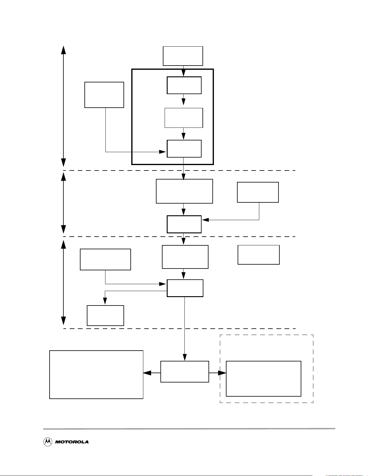
C files
.c, .h
C Compiler
Front End
IR library
CCSC100
.libfiles
IR files
.obj
[IR = Intermediate Representation]
CompilerAssembler
Optimizer
icode
Object library
files
.elb
Assembly files
.sl
Assembler
asmsc100
Object files
.eln
Assembly
files
.asm
Listing
files
.lst
r
e
k
n
i
L
Map
files
.map
“Run-time” Simulator
runsc100
- Execute Program to completion
- C file I/O capability
Figure 2. StarCore Development Process
sc100-ld
Linker
Absolute files
.eld
Introduction to the SC140 Tools
Interactive Simulator
simsc100
- DOS based
3
Page 4

1 File I/O Exercise
The file I/O exercise shows how to use standard ANSI C I/O features with in the current tools suite.
Hands On
1. Create a new text file called
2. Within the io.c file, write code using the ANSI C printf function to display Welcome to
StarCore SC140 Tools
3. Compile the file using
-o option specifies the output file name (for example, io.eld). If the applicat io n does not
The
compile successfully, correct the reported mistake(s) and recompile the application until a successful
compilation occurs.
4. Run the executable
The runsc100 executable is a cycle-a ccu rate run-time simulator. It allows you to run an application to
completion and print out intermedi ate/final results. You can use this executable for quick code
verification and/or debugging purposes.
Congratulations, you have completed Exercise 1.
Good To Know
The SC140 core supports both Big Endian and Little Endian data
representations. Therefore, t he SC140 tools support both modes. By
default, ccsc100 and runsc100 use Little Endian mode.
Big Endian mode can be selected by:
runsc100 io.eld to display Welcome to StarCore SC140 Tools.
io.c.
on the screen (remember to include the header file stdio.h),
ccsc100 io.c -o io.eld.
• specifying the -be option for ccsc100
• specifying the -e option for runsc100
If the code is built using Big Endian mode, it must be run using Big
Endian mode.
Reminder: (memory storage of a = 0x12345678)
Big Endian Mode Little Endian Mode
p:00 1234 p:00 7856
p:02 5678 p:02 3412
4
Introduction to the SC140 Tools
Page 5
Hardware Support on StarCore
2 Integer and Fractional Arithmetic Exercise
One of the strengths of b oth the StarC ore architecture and th e StarCore co mpiler is the ability to pe rform
both fractional and integer arithmetic. This exercise presents a reminder about integer and fractional
arithmeti c representation and then shows how to use the StarCore compiler fractional intrinsics. Values
stored in memory or registers are interpreted differently depending on the operation performed. For
integers, the binary point is considered to be immediately to the right of the LSB. For the fractional case,
the binary point is considered to be immediately to the right of the MSB. Table 1 illustrates this for 16-bit
data values.
Table 1. Interpretation of 16-bit Integer and Fractional Data Values
Binary Representation
0100 0000 0000 0000 0x4000 16384 0.5
0001 0000 0000 0000 0x1000 4096 0.125
0000 0000 0000 0000 0x0000 0 0.0
1100 0000 0000 0000 0xC000 -16384 -0.5
1111 0000 0000 0000 0xF000 -4 096 -0.125
Hexadecimal
Representation
Integer Value
(decimal)
Fractional value
(decimal)
2.1 Hardware Support on StarCore
StarCore has a dual instruction set for operations that produce different results depending on whether
fractional or integer arithmetic is used. The instruction set is complementary when an integer or a
fractional operation leads to the same result, regardless of the operation type: for example, an addition.
The instruction set is dual (as shown in Table 2) in two cases, which automatically take care of data
alignment, zero filling, and sign extension:
• when an integer or a fractional operation leads to a different result depending on the operation
type: for example, a multiplication.
• when data is transferred from/to memory.
Table 2. Fractional and Integer Assembly Language Instructions
Operation Integer Fractional
Multiply impy mpy
Multiply accumulate imac mac
Move move.b, move.w,
move.2w, move.4w
Introduction to the SC140 Tools
move.f, move.2f, move. 4f
5
Page 6

Compiler Support on StarCore
2.2 Compiler Support on StarCore
The StarCore compiler implements fractional arithmetic using built-in intrinsic functions based on integer
data types. Any fractional values or constants must therefore be defined using their integer equivalent.
Useful relationships for deriving these integer representations from the fractional vales are as follows:
16-bit Integer Value = Fractional Va lue * 2
32-bit Integer Value = Fractional Va lue * 2
40-bit Integer Value = Fractional Va lue * 2
The names of the built-in intrinsics conform to the ITU/ETSI basic operation functions. For instance, the
L_mac() intrinsic function is used in the following example (see Figure 3), and a complete li st of the
intrinsic functions for fractional arithmetic can be found in the SC100 C/C++ Compiler User’s Manual.
The example illustrates how the in structions are mapped based on the type of the arithmetic re quired. For
integer arithmetic, the compiler generates integer instructions (for example, imac). For fractional
arithmetic, it generates fractional instructions (for example, mac). Also, move instructions are generated
with correct data alignment.
15
31
39
Integer
long a;
short b, c;
a = a + b * c; a = L_mac(a,b,c);
move.w (r0),d0 move.f (r0) ,d0
imac d0,d1,d2 mac d0,d1,d2
Figure 3. Integer and Fractional Compiler Support
long a;
short b, c;
Fractional
(Supported by intrinsics)
Hands On
The energy of a signal, x, represented by Equation 1, is considered:
N 1–
2
yx
=
∑
i 0=
, (1)
i()
where x(i) is the signal input sa mple at iterat i on i, y is the energy of the signal, and N is the signal len gth.
1. Open t he example file Ex2.c.
Integer Arithmetic
2. Compile the file using ccsc100 -Ot2 Ex2.c -o Ex2.eld where the -Ot2 option optimizes the
code for ti me (Force Pa rallelization).
3. Run the executable using runsc100.
4. Recompile the file with the
6
-S option, which stops the compiler after compilation.
Introduction to the SC140 Tools
Page 7
Compiler Support on StarCore
5. Open the generated assembly file Ex2.sl and look at the integer instructions within the loop.
6. In the box provided here, write down the integer C code and the generated assembly instructions for
the loop. N otice that the first data load is automati cally pipelined in the software.
Integer Arithmetic
C code Generated Assembly code
Fractional Arithmetic
7. For fractional arithmetic, copy and paste the loop of Ex2.c.
The first loop remains unchanged and performs integer calculation while the second loop is modified
to perform fractional arithmetic.
8. In the second loop, replace the integer arithmetic operation with the appropriate fractional intrinsic.
Remember, fractional arithmetic is performed using C compiler intrinsics. In this example, the L_mac
intrinsic is used. Its prototype is:
long int L_mac(long int, short int, short int).
Therefore, the code modifications should be:
a. Create a new variable “fres” of type “long int.”
b. Replace “res += x[i] * x[ i];” with the instruction “fres = L_mac(fres,x[i],x[i]).”
c. Include the file
prototype.h, which contains all the intrinsics prototypes.
d. Add another printf statement to print out the fractional result. The result is sti l l a “long int,” so
“%d” should still be used.
9. Recompile the code with the
-S option and look at the generated assembly file Ex2.sl within the
second loop.
10. In the box provided below, wri te the f racti onal C code and the gen erate d ass embly ins truct ions fo r that
loop.
Fractional Arithmetic
C code Generated Assembly code
Introduction to the SC140 Tools
7
Page 8

Compiler Support on StarCore
11. Compare the fractional assembly instructions generated to the assembly integer instructi ons.
12. Recompile the code without the
-S option to produce an executable file.
13. Run the code using runsc100. The variables “res” and “fres” should print to the screen. What is the
algebraic relationship between these two variables?
Congratulations, you have completed Exercise 2.
Good To Know
To perform fractional operations:
• Intrinsics are used.
• The variable types remain integer.
• The header file prototype.h should be included in
the C source file.
All assembly instructions (compiler generated or hand
written) between square brackets [ ] execute in parallel as
a single execution set.
8
Introduction to the SC140 Tools
Page 9
Compiler Support on StarCore
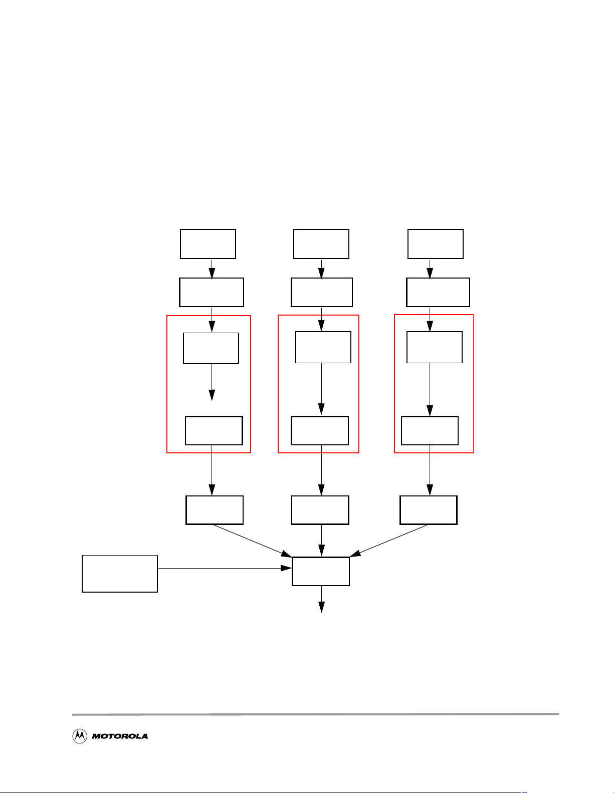
3 Local Versus Global Optimizati on Exercise
The local versus global optimization exercise shows the difference between two C compiler options: local
optimization (the default) and global optimization. Local optimization compiles each file of the project
individually as represented in Figure 4. Global optimization acts as a global binder that links all the
intermediate representation (IR) fi les into one fi le before opt imizing the application. Since all the
application code information is available, this approach enables further optimizations beyond those
achieved using local optimization alone. (Compilation takes longer when global optimization is enabled.)
Global optimization compilation flow is represented in Figure 5.
StarCore C Compiler
Local
Optimization
C files
.c, .h
C compiler
Front End
IR files
.obj
Optimizer
icode
Assembler
asmsc100
C files
.c, .h
C compiler
Front End
IR files
.obj
Optimizer
icode
Assembler
asmsc100
C files
.c, .h
C compiler
Front End
IR files
.obj
Optimizer
icode
Assembler
asmsc100
Object library
files .elb
Linker
Figure 4. StarCore Local Optimizati on
Introduction to the SC140 Tools
9
Page 10

Compiler Support on StarCore
StarCore C Compiler
C files
.c, .h
C Compiler
Front End
IR files
.obj
Global
Optimization
Assembler
asmsc100
C files
.c, .h
C Compiler
Front End
IR files
.obj
Optimizer
icode
Assembler
asmsc100
C files
.c, .h
C Compiler
Front End
IR files
.obj
Assembler
asmsc100
Object Library
Files, .elb
Figure 5. StarCore Global Optimization
Linker
Hands On
The benefit of Global Optimization is most apparent when several files containing cross references are
used, as is often the case in any sizeable application. In this example, two files are used:
• the main file called
Ex3_main.c
• a function file called Ex3_prod.c
The main file, Ex3_main.c, calls a routine defined in the function file Ex3_prod.c, as shown in
Figure 6.
10
Introduction to the SC140 Tools
Page 11
Compiler Support on StarCore
Ex3_main.c
...
main()
{
...
res=Prod(&array1[0],&array2[0]);
...
}
Figure 6. Files for the Local Versus Global Optimization Exercise
1. Open the two files and understand their functionality.
Local Optimization
2. Compil e the two files:
ccsc100 -Ot2 Ex3_main.c Ex3_prod.c -o Ex3.eld
3. Run the code: runsc100 -t Ex3.eld.
The
-t option for runsc100 enable s the cyc le coun t ge nerat ion. Writ e the cy cle cou nt i n the box below:
Ex3_prod.c
...
long Prod(short a1[], short
a2[])
{
...
}
Local Optimization (Default Mode) Cycle Count
Global Optimization
4. Compile the files using global optimization:
ccsc100 -Ot2 -Og Ex3_main.c Ex3_prod.c -o Ex3_glo.eld
where -Og is the global optimization option.
5. Run the code:
runsc100 -t Ex3_glo.eld. Write the cycle count in the box below:
Global Optimization (-Og option) Cycle Count
Introduction to the SC140 Tools
11
Page 12

Compiler Support on StarCore
To understand how global optimization makes best use of available information, perform these steps:
6. Recompile the application with
ccsc100 -Ot2 Ex3_main.c Ex3_prod.c -S.
7. Rename the
.sl files as Ex3_main1.sl and Ex3_prod1.sl.
-S option (Stop After Compilation) and with the local optimization:
8. Open the files to see what the compiler has produced.
9. Enable global optimizatio n:
10. Open
Ex3_main.sl to see what the compiler has produced.
ccsc100 -Ot2 -Og Ex3_main.c Ex3_prod.c -S.
Since the compiler has all information on the application, it optimizes the application further than with
local optimization. The compiler avoids calling the function by in-lining the function into the main
code (as shown in
Ex3_main.sl). Theref ore, it eliminates the cycle overhead associated with
jumping to and returning from the function and passing the parameters to the functions.
Congratulations, you have completed Exercise 3.
Good To Know
• Global optimization requires a longer compilation
time than local optimization.
• Global optimization further opti mizes the application
speed.
4 Memory Alignment Exercise
The memory alignment exercise shows the usage of wide data moves and the necessary alignments for
performing these moves. The SC140 memory has byte granularity (as represented in Figure7). Two
arithmetic address units (AAUs) transfer the data from memory to the 4 ALUs (and vice versa) via two
64-bit data buses. Each data bus allows the transfer of up to eight bytes from memory to the data registers
in one cycle (and vice versa).
If the compiler must generate the wide data move instructions available in the StarCore instruction
set—such as move.2w, move.2f, move.4w, and so on—data must be correctly aligned in memory. This is
due to the way the address and data buses operate for multi-byte accesses in the StarCore architecture. The
compiler does not generate wide data move instructions if alignment is not guaranteed. However, if a
function is implemented in ass embly la nguage a nd uses wi de dat a move ins truct ions, you must e nsure t hat
the data is aligned on the appropriate boundary. Otherwise, the wrong data is transferred.
P:0x00
P:0x08 CDAB8967452301 EF
P:0x10
....
Figure 7. Memory Granularity
ABFFEEDDCCBBAA BC
8 bytes
8 bytes
12
Introduction to the SC140 Tools
Page 13

Compiler Support on StarCore
The following instruc tions bring m ore than one byte at a time to the data re gister:
move.w (Rx), Dn Transfer one 16-bit word from memory (2 bytes)
move.f (Rx), Dn Transfer one 16-bit word from memory (2 bytes)
move.2w (Rx), Dh Transfer two 16-bit words from memory (4 bytes)
move.2f (Rx), Dh Transfer two 16-bit words from memory (4 bytes)
move.4w (Rx), Dk Transfer four 16-bit words from memory (8 bytes)
move.4f (Rx), Dk Transfer four 16-bit words from memory (8 bytes)
move.2l (Rx), Dh Transfer two 32-bit words from memory (8 bytes)
where x spans from 0 to 15 and the data register notations are as follows:
• Dn represents D0, D1, D2, D3, D4, D5, D6, D7, D8, D9, D10, D11, D12, D13, D14, or D15.
• Dh represents D0:D1, D2:D3, D4:D5, D6:D7, D8:D9, D10:D11, D12:D13, or D14:D15.
• Dk represents D0:D1:D2:D3, D4:D5:D6:D7, D8:D9:D10:D11, or D12:D13:D14:D15.
Most processors requi r e ope ra nds to be aligned in me mory and multiple-operand loa d/ st ores to be aligned.
For example, a double operand load requires an even address, and a quad operand load requires a double
even address. These r est rictions reduce t he compl exity of the addre ss generation hardwa re, particularly for
modulo addressing. For example, let us consider the move.4w (Rx), Dk instruction—more specifically,
move.4w (R0),D0:D1:D2:D3 (four 16-bit words are moved from the memory address of R0 into the
data registers D0, D1, D2, and D3, respectively) . The data must align on an 8-byte boundary, so the address
contained in R0 should be a multiple of eight. The examples in Figure 8 further illustrate this point.
.
Aligned Not Aligned
Bringing one word from memory
move.w (r0),d0 where r0 = 0x0 or 0x2 move.w (r0),d0 where r0 = 0x1 or 0x3
P:0x00
Aligned on a 2-byte boundary
Correct Operation: brings either AABB
(if R0 = 0x0) or CCDD (if R0=0x2)
move.2w (r0),d0:d1 where r0 = 0x0 or 0x4
P:0x00 DDCCBBAA P:0x00 DDCCBBAA
Aligned on a 4-byte boundary
Correct Operation: brings AABB CCDD
(if R0 = 0x0)
DDCCBBAA P:0x00 DDCCBBAA
Not Aligned on a 2-byte boundary
Erronenous Operation: br ing s wrong
data in d0
Bringing two words from memory
move.2w (r0),d0:d1 where r0 = 0x1, 0x2 or 0x3
EE
Not Aligned on a 4-byte boundary
Erronenous Operation: brings wrong
data in d0:d1
EE
Figure 8. Alignment Considerations
Introduction to the SC140 Tools
13
Page 14

Compiler Support on StarCore
The following instructions require data to be aligned on the specified boundaries:
move.w (r0),d0
2-byte boundary
move.f (r0),d0 2-byte boundary
move.2w (r0), d0:d1 4-byte boundary
move.2f (r0), d0:d1 4-byte boundary
move.4w (r0),d0:d1:d2:d3 8-byte boundary
move.4f (r0),d0:d1:d2:d3 8-byte boundary
move.l (r0),d0 8-byte boundary
move.2l (r0),d0:d1 8-byte boundary
Hands On
1. Open the Ex4.c file, which contains a series of assembly instructions within a C framework using
asm statements. For alternative (and nicer) ways of incorporating assembly code, consult the SC100
C/C++ Compiler User’s Manual.
2. Look at the assembly instructions to understand the wide data move instructions. Notice that the code
comprises two sections: the first section with aligned data and the second with non-aligned data.
3. For each instruction, write the result you expect from each section in the boxes provided here (in the
Expected Columns). Array “data[ ]” is of type long int and therefore aligns on a 4-byte boundary.
data: 0x01 0x231 0x45 0x67 0x89 0xAB 0xCD 0xEF
0xAA 0xBB 0xCC 0xDD 0xEE 0xFF 0x11 0x22
Simulator
move #data,r0
r0
Expected
0100000000
move.w (r0),d0
move.2w (r0),d0:d1
move.2f (r0),d2:d3
move.4w (r0),d4:d5:d6:d7
move.2l (r0),d8:d9
d0
d0
d1
d2
d3
d4
d5
d6
d7
d8
d9
First Code Section
14
Introduction to the SC140 Tools
Page 15

Compiler Support on StarCore
data: 0x01 0x23 0x45 0x67 0x89 0xAB 0xCD 0xEF 0xAA 0xBB 0xCC 0xDD
0xEE 0xFF 0x11 0x22
move #data+2,r0
move.w (r0),d0
move.2w (r0),d0:d1
move.2f (r0),d2:d3
move.4w (r0),d4:d5:d6:d7
move.2l (r0),d8:d9
r0
d0
d0
d1
d2
d3
d4
d5
d6
d7
d8
d9
Expected
Simulator
0102000000
Second Code Section
4. Compile the Ex4.c file: ccsc100 -be Ex4.c -o Ex4.eld.
The Big Endian (
-be) option is used in this exercise to make it easier to read the data in the simu lator
memory window. If desired, the Little Endian mode can also be used.
5. Run the GUI simulator: guisc100. In the simulator command window, type
simulator in Big Endian mode.
6. Open an assembly window: Windows->Assembly.
7. Load the file:
8. Set a breakpoint on “main” by typing
9. Type
go. The code should now be at the start of main.
Load Ex4.eld.
break _main into the command window.
10. Open a memory window: Windows->Memory and click OK.
11. Type
data into the Scroll box (of the memory window) to display the contents of the array data[ ]
defined in
Ex4.c. Verify that these contents are as expected.
Introduction to the SC140 Tools
reset d m1 to put the
15
Page 16

Compiler Support on StarCore
12. Type next to step through the code.
13. Look at the register contents in the session window and write the values in the Simulator Columns
boxes above for both sections.
Congratulations, you have completed Exercise 4.
.
Good To Know
• Unaligned data accesses lead to erroneous results.You must
consider these issues when developing assembly code.
5 Split Summation Exercise
The split summation exercise shows how to mod ify C code us ing the split summation te chnique to get
better parallelization. The split summation technique helps to maximize the multiple-ALU loading by
performing arithmetic operations in parallel while requiring little algorithmic or code modifications. To
illustrate this technique, the example performs the the optimization of the energy of a signal calculation
already considered in Exercise 2. The power calculation is represented in Equation 2:
N 1–
2
yx
=
∑
, (2)
i()
where x(i) is the signal input sam ple at iteration i, y is the power of the signal, and N is the signal length.
As Exercise 2 shows, computing the signal energy directly from Equation 2 results in the use of only one
ALU out of the four with one multiply-accumulate operation performed at each iteration. However, the
split summation technique can load all four ALUs. Equation 2 is expanded as follows:
N 1–
y
=
Equation 3 explicitly h igh lights t he four mult iply-acc umula te operat ions t hat ca n be pe rfor med in par allel .
Figure 9 highlights where each parallel execution is represented by Group 0, Group 1, and so on. It also
shows that the sample number, i, from one group to the other is incremented by four.
y = x(i) * x(i) + x(i+1) * x(i+1 ) + x( i+2) * x(i+2) + x(i+3) * x( i+3 )
+ x(i+4) * x(i+4) + x(i+5) * x(i+5) + x(i+6) * x(i+6) + x(i+7) * x(i+7)
+ ...
Figure 9. Signal Power Calculation Using the Split Summation Technique
xi()xi() xi 1+()xi 1+()xi 2+()xi 2+()xi 3+()xi 3+()+++
∑
i 048…,,,=
Group 0 (First cycle)
Group 1 (Second cycle)
(3)
16
Introduction to the SC140 Tools
Page 17

Hands On
1. Open the Ex5.c file.
2. Build the code with -Ot2, then run it and notice the output result.
Compiler Support on StarCore
3. Split the current implementation of the loop (that is,
res = L_mac(res, x[i], x[i]);) into four
independent equations as represented in Figure 9.
“Independent” means that the f our equations are accumulat ed into diffe rent variabl es. Therefor e, create
four variables for each product. Tip: Watch your index increment.
4. Recompile the file and run it. The output result should be the same as before.
5. Recompile with the
-S option and view the .sl file.
6. Your code is optimized when the loop is only one cycle and computes four operations at a time.
If the inner lo op is equal to one cycle for four operations and the result is still correct, congratulations.
You have completed Exercise 5.
7. In the box provided below, write the optimized inner loop code:
C Code
Generated Assembly Code
The split summation technique allows full use of all four ALUs, reducing the cycle time by more than 70
percent relative to use of a single ALU. The 4-ALU technique does not guarantee bit-exactness with the
single-ALU technique be cause the order of accumulati on is differe nt. Using the 4-ALU t echnique there fore
has implications in applications that are defined by bit-exact standards, such as speech coding standards
from ITU, ETSI,TIA/EIA, and so on.
Introduction to the SC140 Tools
17
Page 18

Compiler Support on StarCore
Good To Know
• The use of four variables removes t he accumulat ion depende ncy t hat is r equired
for parallelism.
• Bit exact considerations must be understo od if this technique is used:
overflow/saturation character istics may change during split summation.
6 Multi-Sample Exercise
The multi-sample exercise demonstrates the multisample technique. As the exercise in Section 5 shows,
the split summation techni que all ows a sum of products operati on to be ca lculated using all four ALUs by
evaluating four intermediate products at a time. However, it does not guarantee bit-exact agreement with
serially accumulat i ng e ach intermediate produc t using a single ALU. To ensure bit-exactness, the order of
summation must be preserved by performing each intermediate product/accumulation in turn.Therefore,
the intermediate pr oducts cann ot be evalua ted in para llel. Fur thermore, the sp lit su mmation techn ique may
not be suited for the application. Other techniques can be used where it is possible to evaluate one
intermediate product f rom each of f our output sample calculations in parallel. Consider the FIR filtering
operation described by Equation 4:
N 1–
yn() aixn i–()
=
∑
i 0=
, for 0 ≤ n < L(4)
A C code implementation of this operation typically resembles the implementation of Ex6.c. To use all
four ALUs, the operations can be grouped as illustrated in the following equation:
yn() a0xn() a1xn 1–()a2xn 2–()a3xn 3–()…a
yn 1+()a
yn 2+()a0xn 2+()a1xn 1+()a2xn() a3xn 1–()…a
yn 3+()a
xn 1+()a1xn() a2xn 1–()a3xn 2–()…a
0
xn 3+()a1xn 2+()a2xn 1+()a3xn() … a
0
Group 0 Group 1 Group 2 Group 3 Group N-2 Group N-1
xn N– 2+()a
N 2–
xn N– 3+()a
N 2–
xn N– 4+()a
N 2–
xn N– 5+()a
N 2–
N 1–
N 1–
N 1–
N 1–
xn N– 1+()+++++ +=
xn N– 2+()+++++ +=
xn N– 3+()+++++ +=
xn N– 4+()+++++ +=
(5)
In Equation 5, the product s and ac cumul at io ns wit hin each group are calculat ed in parallel, but the gro ups
themselves are evaluated in sequence, thus preserving the order of accumulation, which in turn preserves
the bit-exactness of Equation 4. Therefore, parallelization is achieved by processing multiple samples in
parallel rather than multiple intermediate products belonging to only one output sample. When one group
(for example, Group 2) is evaluated, only two words of data need to be loaded for the next group
(Group 3): a
and x(n-3). The other values needed for the calculations in Group 3—x(n-2), x(n-1), and
3
x(n)—should already exist in the DSP registers from the calculation of Group 2. The result is a reduction
in memory bandwidth requirements that increases code efficiency.
18
Introduction to the SC140 Tools
Page 19

Compiler Support on StarCore
Hands On
1. Open the Ex6.c file.
2. Compile Ex6.c using the -Ot2 option. Run the code and verify that the output is correct.
See the comments in
3. Recompile
Ex6.c using the -Ot2 and -S options. Examine the assembly language file Ex6.sl to see
Ex6.c for the correct values of y[].
how the inner loop is compiled.
Intermediate Version: Compromise Between Memory and Speed
4. Save Ex6.c as Ex6_1.c.
5. Change the C code of
Ex6_1.c according to the following steps:
a. Process the first four samples at a time:
Replace the implementation of “y(n) = ai * x(n)” with the equations defined as Group 0 in
Equation 5.
b. Replace x(n), x(n+1), x(n+2), x(n+3) with variables (for example, var0, var1, var2, var3,
respectively), as follows:
res0 += a[i] * var0;
res1 += a[i] * var1;
res2 += a[i] * var2;
res3 += a[i] * var3;
Group 0
This processes the first gr oup (Gr oup 0). To process the remaining gro ups, Group 1 and so on, the
values from var0, var1, and var2 from Group 0 must be transferred to var1, var2, var3,
respectively, for processing Group 1.
c. Transfer the values in var1, var2, and var3 and load the new sample (x(n-1)) into var0.
6. Compile the code with the
-Ot2 option, and run the code to verify that the correct output values are
obtained.
7. Recompile
Ex6_1.c using the -Ot2 and -S options. Th e inner loop s hou ld be on ly two c ycles long. I f
not, return to Step 5.
During each iteration of the loop, the coefficient, a[i], is loaded into a data register. The data value,
x[n-1-i], is lo ade d i nto another data r egister. The values in the other t hre e registers are r eus ed, but they
must first be transferred into the registers where the four MAC instructions expect them. This transfer
results in two clock cycles for every four MAC instructions.
8. In the box on the following page, write the code for the intermediate version.
Introduction to the SC140 Tools
19
Page 20

Compiler Support on StarCore
C Code
Generated Assembly Code
Further Speed Optimization
The register-to-register transfers can be eliminated by expanding the inner loop so that each group of four
MAC instructions uses the data registers already containing the required data values. This yields faster
code, but code size is greater.
9. Save
10. In
Ex6_1.c as Ex6_2.c.
Ex6_2.c, “unroll” the inner loop instructions four times so that the first four groups (Group 0,
Group 1, Group 2, and Group 3) are all processed in the lo op. This loop expansion avoids transferr in g
data. You must reduce the number of loop iteratio ns by a factor of four to compensate for the fact t hat
the loop is unrolled by a factor of 4.
If your inner loop consumes just four cycles, and your code still produces the correct output,
congratulations. You have completed Exercise 6.
Notice that each group of four MAC operations and two data load operations now requires just one
processor cycle, which is half the time required by the filtering operation and a quarter of the time required
by a single-ALU DSP device. However, the code size for the inner loop has increased by a significant
amount (approximately four times that of the second implementation), and this must be weighed up
against the cycle-count performance improvements obtained.
Table 3 summarizes the main
characteristics of the multi-sample technique .
Table 3. Inner Loop Characteristics of Multi-sample and Single-sample Techniques.
Characteristic Single-sample Algorithm Multi-sample Algorithm
Cycle count N N/4
Registers used Fewer More
Sample delay 1 4
20
Introduction to the SC140 Tools
Page 21

Compiler Support on StarCore
Table 3. Inner Loop Characteristics of Multi-sample and Single-sample Techniques. (Continued)
Characteristic Single-sample Algorithm Multi-sample Algorithm
Number of memory moves (bandwidth) 2N N/2
Code size Small Large
7 Control Code: The True Bit Exercise
The True bit exercise shows how the compiler uses the True bit and how you can help the compiler to
improve the performance. The True bit is set/cleared by compare or test instructions. The use of the True
bit as a control flag together with DSP-specific code makes the SC140 very powerful for applications
including both control and DSP code. The True bit can affect conditional branching as well as conditional
execution of groups of instructions.
Conditional branching includes:
• BT/BF: Branch relati ve if True bit is True/False.
• BTD:BFD: Branch delayed relative if True bit is True/False.
• JT/JF: Jum p if True bit is True/False.
• JTD/JFD: Jump delayed if True bit is True/False.
Conditional execution of instructions includes:
• IFT/IFF: IF True bit is True/False.
• IFA: IF always, which is unconditionally executed with IFT/IFF.
The conditional execution set combinations are very flexible and are represented in Figure 10, which
represents the maximum number of ALUs (that is, two) and one Arithmetic Address Unit (AAU) per
subset. The C compiler automatically generates the conditional execution set, and some examples are
provided to highlight potential code optimization.
AAU1 AAU2ALU2 ALU3 ALU4ALU1
AAU1 AAU2ALU2 ALU3 ALU4ALU1
AAU1 AAU2ALU2 ALU3 ALU4ALU1
IFTIFA
IFFIFT
IFFIFA
Figure 10. Control Instructions Using the True Bit
Introduction to the SC140 Tools
21
Page 22

Compiler Support on StarCore
Hands On
1. Open the example Ex7.c file.
2. Understand the conditional test in the code.
3. Compile the project with the
4. Open the generated assembly file
-Ot2 and -S options.
Ex7.sl, and look at the conditional instructions within the loop.
5. In the box provided here, write down how many execution sets are within the loop:
Optimized for Time Optimized for Space
6. Recompile using the compiler optimization option for code size (
7. Open the generated assembly file
Ex7.sl, and look at the conditional instructions within the loop.
-Os option).
Write down how many execution sets are within the loop in the box.
8. Save Ex7.c as Ex7_1.c.
9. Modify the prog ram to obtain two c ycles within th e loo p. Tip: consider us ing a temporary var iab le for
both storing the immediate value of the
10. Compile the code using the
-Ot2 option.
array1 and the conditional test.
11. Open the file
Ex7_1.sl.
12. If you have obtained two cycles for the inner loop, congratulations. If you have not, please try again.
13. In the following box, write the optimized C code.
C Code
Generated Assembly Code
22
Introduction to the SC140 Tools
Page 23

Compiler Support on StarCore
8 Calling an Assembly Routine From C Exercise
Practical DSP application commo nly use a mixt ure of C an d asse mbly langu age . This exer cise shows how
an assembly language function can be called from C code. The code for this exercise is contained in two
Ex8.c and addvecs.asm. The C code in Ex8.c ca lls th e assembl y languag e functi on, addvec s(), in
files:
addvecs.asm, to add two v ectors together and retu rn the sum of all the elemen ts of the resultant
file
vector. The prototype for addvecs() is as follows:
short add_vecs
(
short x[], /* Input vector */
short y[], /* Input vector */
short z[], /* Output vector */
short length /* Length of vectors */
);
Four parameters are passed to addvecs(). The first three are pointers to arrays and are therefore 32-bit
values (addresses are 32-bits in StarCore). The fourth parameter is the length of the vectors and is a 16-bit
value. The mechanism by which parameters are passed is specified in the application binary interface
(ABI). Generally speaking, this ABI specifies the following calling convention:
• The first parameter is p assed in d0 if i t is a numeric scalar or in r0 if it is an address.
• The second parameter is passed in d 1 if it is a nume ric scalar or in r1 if it is an address.
• Subsequent parameters are pushed onto the stack.
• The return value (if any) is pas sed back to the call ing functi on in d0 if it is a numeric scal ar or in r0
if it is an address.
For simple functions with two parameters or fewer, the stack is not used to pass parameters, and it may be
possible to write the entire assembly language function without explicitly using the stack at all. In general,
however, the stack is used to pass parameters into the function and to store local variables. Its contents are
as shown in Figure 11. Just prior to the function call, parameters 3, 4, 5, and so on are pushed onto the
stack (in reverse order ), and parameters 1 and 2 are st or ed in d0/r0 and d1/r1, as described previously. The
function is then called, and the return address and status register contents are pushed onto the stack by the
jsr or bsr instruction. If the called function modifies register d6, d7, r6, or r7, it should first save them on
the stack and then restore them before returning. All other registers are free for use without saving or
restoring them. The calling functi on must save these registers if it needs their values to be preserved. On
function exit, the status register contents and return address are popped from the stack (by the rts
instruction), and the calling function deallocates the stack space used to pass parameters 3, 4, 5, and so on.
Introduction to the SC140 Tools
23
Page 24

Compiler Support on StarCore
High Address
SP
Local
Variables
(if any)
SP
(Current)
SP
SP
SP
Return
Address
Parameters
3, 4, 5, ...
Saved
Registers
Return
Address
Parameters
3, 4, 5, ...
SP
Return
Address
Parameters
3, 4, 5, ...
SP
Parameters
3, 4, 5, ...
SP
¹ ²³ ¼½ª
¹ Prior to function call
Low Address
² On entry to function
³ During function execution
¼ Prior to exit from function
½ On return from function
ª Calling function deallocates parameters on stack
Figure 11. Typical Stack Contents During Function Execution
Therefore, for the func tion addvecs(), parameters x[], and y [] are passed in r0 and r1, while z[] and M are
passed on the stack.
Hands On
1. Open the
Ex8.c and addvecs.asm files, and familiarize yourself with the code.
2. In addvecs.asm are t wo constant s, Z_OFFSET and M_ OFFSET, whose valu es are not set and whic h
are represented by que sti on mar ks ( ??? ). These offsets pull z[] and M fr om the s ta ck. Fi nd th e li nes of
code that p erform this task.
3. Before the code can be built, you must assign values to Z_OFFSET and M_OFFSET. To help you to
do this, Figure 12 shows the stack on entry to addvecs().
24
Introduction to the SC140 Tools
Page 25

SP
On function entry
4
4
Status Register
Return Address
Compiler Support on StarCore
}
Pushed on stack by jsr/bsr instruction
4
2
SP
Prior to function call
4. In the box provided here, write what you think the offsets should be:
Z_OFFSET
M_OFFSET
5. Modify the
6. Build the code.
7. Run the code:
8. The following output should be displayed:
addvecs.asm file to incorporate your offset values.
runsc100 Ex8.eld.
z = [3, 5, 7, 9, 11, 13, 15, 17]
sum = 80
2
Figure 12. Stack Contents on Entry to advecs()
&z[0]
M
Parameters pushed onto stack prior to jsr/b
}
9. If the above output is displayed, your offset values are correct.
10. Rebuild the code, this time with the
11. Open the generated assembly file
12. Find the instructions that put z[] and M onto the stack just prior to the function call. Write the offsets in
the box provided here:
Z_OFFSET
M_OFFSET
-S option.
Ex8.sl, and find the call to addvecs().
Introduction to the SC140 Tools
25
Page 26

Compiler Support on StarCore
13. Are the offsets used in Ex8.c the same as the offsets used in addvecs.asm? If not, can you explain
why?
Congratulations, you have completed Exercise 8.
Good To Know
The stack pointer must always be a multiple of 8. It is il legal to
increment it by a non-multiple of 8.
9 The Challenge
This section presents you with a challenge involving an example that implements a complex scalar
product. The objective of this session is to optimize the code from
minimum number of cycles.
Hands On
Ex9.c for speed and obtain the
1. Put into practice the techniques previously explained to optimize
The original number of cycles in the inner loop is:
Original (Inner loop)
So far, after having modified the code, your best result is:
Your Best (Inner loop)
The optimized C code result is:
Target (Inner loop)
1 cycle with ALUs and AAUs 100 percent used
Ex9.c.
If your best result is within 10 percent of the target result, congratulations. You have completed all the
exercises and the challenge as well.
26
Introduction to the SC140 Tools
Page 27

Compiler Support on StarCore
10 Solutions to Exercises
Exercise 1:
/*****************************************************************************
* MOTOROLA INC.
* SEMICONDUCTOR PRODUCTS SECTOR
* COPYRIGHT 1999 MOTOROLA INC.
*******************************************************************************
* INTRODUCTION TO THE SC140 TOOLS
* Developed by MOTOROLA SPS/NCSG/WISD
*******************************************************************************/
#include <stdio.h>
main()
{
printf(“Welcome to StarCore SC140 Tools\n”);
}
Exercise 2:
/*****************************************************************************
* MOTOROLA INC.
* SEMICONDUCTOR PRODUCTS SECTOR
* COPYRIGHT 1999 MOTOROLA INC.
*******************************************************************************
* INTRODUCTION TO THE SC140 TOOLS
* Developed by MOTOROLA SPS/NCSG/WISD
*******************************************************************************/
#include <stdio.h>
#include <prototype.h>
short x[12] = {0,1,2,3,4,5,6,7,8,9,10,11};
main()
{
short i;
long res=0;
long fres=0;
for(i=0;i<12;i++)
{
res += x[i] * x[i];
}
for(i=0;i<12;i++)
{
fres = L_mac(fres,x[i],x[i]);
Introduction to the SC140 Tools
27
Page 28

Compiler Support on StarCore
}
printf("The integer result is: %d (0x%x)\n",res,res);
printf("The fractional result is: %d (0x%x)\n",fres,fres);
}
Exercise 3:
No code modification is required.
Exercise 4:
data: 0x01 0x23 0x45 0x67 0x89 0xAB 0xCD 0xEF
0xAA 0xBB 0xCC 0xDD 0xEE 0xFF 0x11 0x22
move #data,r0
move.w (r0),d0
move.2w (r0),d0:d1
move.2f (r0),d2:d3
move.4w (r0),d4:d5:d6:d7
move.2l (r0),d8:d9
r0
d0
d0
d1
d2
d3
d4
d5
d6
d7
d8
d9
Expected
0000 0123
00
0000 0123
00
0000 4567
00
0123 0000
00
4567 0000
00
0000 0123
00
0000 4567
00
FFFF 89AB
FF
FFFF CDEF
FF
0123 4567
00
89AB CDEF
FF
Simulator
0000 0123
00
0000 0123
00
0000 4567
00
0123 0000
00
4567 0000
00
0000 0123
00
0000 4567
00
FFFF 89AB
FF
FFFF CDEF
FF
0123 4567
00
89AB CDEF
FF
28
Aligned
Introduction to the SC140 Tools
Page 29

Compiler Support on StarCore
data: 0x01 0x23 0x45 0x67 0x89 0xAB 0xCD 0xEF
0xAA 0xBB 0xCC 0xDD 0xEE 0xFF 0x11 0x22
move #data+2,r0
move.w (r0),d0
move.2w (r0),d0:d1
move.2f (r0),d2:d3
move.4w (r0),d4:d5:d6:d7
move.2l (r0),d8:d9
r0
d0
d0
d1
d2
d3
d4
d5
d6
d7
d8
d9
Expected
0000 4567
00
0000 4567
00
FFFF 89AB
FF
4567 0000
00
89AB 0000
FF
0000 4567
00
FFFF 89AB
FF
FFFF CDEF
FF
FFFF AABB
FF
4567 89AB
00
CDEF AABB
FF
Simulator
0000 4567
00
0000 0123
00
0000 4567
00
0123 0000
00
4567 0000
00
0000 0123
00
0000 4567
00
FFFF 89AB
FF
FFFF CDEF
FF
0123 4567
00
89AB CDEF
FF
Aligned/Not Aligned
The crosses indicate that the results provided by the simulator are not-aligned operations. If this is not
taken into account, unpredict able results can occur when migrat ing to the hardware (which re quires aligne d
data).
Introduction to the SC140 Tools
29
Page 30

Compiler Support on StarCore
Exercise 5:
/*****************************************************************************
* MOTOROLA INC.
* SEMICONDUCTOR PRODUCTS SECTOR
* COPYRIGHT 1999 MOTOROLA INC.
*******************************************************************************
* INTRODUCTION TO THE SC140 TOOLS
* Developed by MOTOROLA SPS/NCSG/WISD
*******************************************************************************/
/* Split Summation Technique Exercise */
#include <stdio.h>
#include <prototype.h>
short x[12] = {0,1,2,3,4,5,6,7,8,9,10,11};
main()
{
short i;
long res1=0, res2=0, res3=0, res4=0;
for(i=0;i<12;i+=4)
{
res1 = L_mac(res1, x[i], x[i]);
res2 = L_mac(res2, x[i+1], x[i+1]);
res3 = L_mac(res3, x[i+2], x[i+2]);
res4 = L_mac(res4, x[i+3], x[i+3]);
}
/* To optimise the code further break the following dependency */
/* res1 = res1 + res2 + res3 + res4; */
/* into */
res1 = res1 + res2;
res3 = res3 + res4;
res1 = res1 + res3;
printf("Result = %d (0x%x)\n", res1,res1);
}
30
Introduction to the SC140 Tools
Page 31

Compiler Support on StarCore
Exercise 6:
Intermediate version: Compromise between Memory and Speed
/*****************************************************************************
* MOTOROLA INC.
* SEMICONDUCTOR PRODUCTS SECTOR
* COPYRIGHT 1999 MOTOROLA INC.
*******************************************************************************
* INTRODUCTION TO THE SC140 TOOLS
* Developed by MOTOROLA SPS/NCSG/WISD
*******************************************************************************/
/* Multi-sample technique Exercise on an FIR Filter */
#include <stdio.h>
#include <prototype.h>
short a[12]={0x1000,0x2000,0x3000,0x4000,0x5000,0x6000,
0x7000,0x8000,0x9000,0xA000,0xB000,0xC000};
short input[32+11]={0,0,0,0,0,0,0,0,0,0,0, /* zero-padding */
0x0100,0x0200,0x0300,0x0400,0x0500,0x0600,0x0700,0x0800,
0x0900,0x0A00,0x0B00,0x0C00,0x0D00,0x0E00,0x0F00,0x1000,
0x1100,0x1200,0x1300,0x1400,0x1500,0x1600,0x1700,0x1800,
0x1900,0x1A00,0x1B00,0x1C00,0x1D00,0x1E00,0x1F00,0x2000};
short y[32];
/**********************************************************************
*** For reference, the following output should be observed after ***
*** running the code. ***
**********************************************************************
* *
* y[0] = 0x0020 *
* y[1] = 0x0080 *
* y[2] = 0x0140 *
* y[3] = 0x0280 *
* y[4] = 0x0460 *
* y[5] = 0x0700 *
* y[6] = 0x0A80 *
* y[7] = 0x0D00 *
* y[8] = 0x0EA0 *
* y[9] = 0x0F80 *
* y[10] = 0x0FC0 *
* y[11] = 0x0F80 *
* y[12] = 0x0F40 *
* y[13] = 0x0F00 *
* y[14] = 0x0EC0 *
* y[15] = 0x0E80 *
* y[16] = 0x0E40 *
* y[17] = 0x0E00 *
Introduction to the SC140 Tools
31
Page 32

Compiler Support on StarCore
* y[18] = 0x0DC0 *
* y[19] = 0x0D80 *
* y[20] = 0x0D40 *
* y[21] = 0x0D00 *
* y[22] = 0x0CC0 *
* y[23] = 0x0C80 *
* y[24] = 0x0C40 *
* y[25] = 0x0C00 *
* y[26] = 0x0BC0 *
* y[27] = 0x0B80 *
* y[28] = 0x0B40 *
* y[29] = 0x0B00 *
* y[30] = 0x0AC0 *
* y[31] = 0x0A80 *
**********************************************************************/
main()
{
long res0, res1, res2, res3;
short var0, var1, var2, var3;
short n, i, *x_ptr;
x_ptr = &input[14]; /* x_ptr points to input[11], which is x[3] */
for(n=0; n<32; n+=4)
{
res0 = 0;
res1 = 0;
res2 = 0;
res3 = 0;
var3 = *x_ptr--; /* var3 = x[n+3] */
var2 = *x_ptr--; /* var3 = x[n+2] */
var1 = *x_ptr--; /* var3 = x[n+1] */
var0 = *x_ptr--; /* var3 = x[n] */
/*** x_ptr now points to x[n-1] ***/
for(i=0; i<12; i++)
{
res0 = L_mac(res0, a[i], var0);
res1 = L_mac(res1, a[i], var1);
res2 = L_mac(res2, a[i], var2);
res3 = L_mac(res3, a[i], var3);
var3 = var2;
var2 = var1;
var1 = var0;
32
Introduction to the SC140 Tools
Page 33

var0 = *x_ptr--; /* var0 = x[n-i-1] */
}
/*** Truncate results and store in y[] ***/
y[n] = extract_h(res0);
y[n+1] = extract_h(res1);
y[n+2] = extract_h(res2);
y[n+3] = extract_h(res3);
x_ptr += 20; /* Increment pointer by 20 to point to x[n+7]
for next iteration */
}
/*** Print results, y[] ***/
for (n=0; n<32; n++)
{
printf ("y[%d] = 0x%04hX\n", n, y[n]);
}
}
Compiler Support on StarCore
Further Optimizing the Speed
/*****************************************************************************
* MOTOROLA INC.
* SEMICONDUCTOR PRODUCTS SECTOR
* COPYRIGHT 1999 MOTOROLA INC.
*******************************************************************************
* INTRODUCTION TO THE SC140 TOOLS
* Developed by MOTOROLA SPS/NCSG/WISD
*******************************************************************************/
/* Multi-sample technique Exercise on an FIR Filter */
#include <stdio.h>
#include <prototype.h>
short a[12]={0x1000,0x2000,0x3000,0x4000,0x5000,0x6000,
0x7000,0x8000,0x9000,0xA000,0xB000,0xC000};
short input[32+11]={0,0,0,0,0,0,0,0,0,0,0, /* zero-padding */
0x0100,0x0200,0x0300,0x0400,0x0500,0x0600,0x0700,0x0800,
0x0900,0x0A00,0x0B00,0x0C00,0x0D00,0x0E00,0x0F00,0x1000,
0x1100,0x1200,0x1300,0x1400,0x1500,0x1600,0x1700,0x1800,
0x1900,0x1A00,0x1B00,0x1C00,0x1D00,0x1E00,0x1F00,0x2000};
short y[32];
/**********************************************************************
*** For reference, the following output should be observed after ***
*** running the code. ***
**********************************************************************
* *
Introduction to the SC140 Tools
33
Page 34

Compiler Support on StarCore
* y[0] = 0x0020 *
* y[1] = 0x0080 *
* y[2] = 0x0140 *
* y[3] = 0x0280 *
* y[4] = 0x0460 *
* y[5] = 0x0700 *
* y[6] = 0x0A80 *
* y[7] = 0x0D00 *
* y[8] = 0x0EA0 *
* y[9] = 0x0F80 *
* y[10] = 0x0FC0 *
* y[11] = 0x0F80 *
* y[12] = 0x0F40 *
* y[13] = 0x0F00 *
* y[14] = 0x0EC0 *
* y[15] = 0x0E80 *
* y[16] = 0x0E40 *
* y[17] = 0x0E00 *
* y[18] = 0x0DC0 *
* y[19] = 0x0D80 *
* y[20] = 0x0D40 *
* y[21] = 0x0D00 *
* y[22] = 0x0CC0 *
* y[23] = 0x0C80 *
* y[24] = 0x0C40 *
* y[25] = 0x0C00 *
* y[26] = 0x0BC0 *
* y[27] = 0x0B80 *
* y[28] = 0x0B40 *
* y[29] = 0x0B00 *
* y[30] = 0x0AC0 *
* y[31] = 0x0A80 *
**********************************************************************/
main()
{
long res0, res1, res2, res3;
short var0, var1, var2, var3;
short n, i, *x_ptr;
x_ptr = &input[14]; /* x_ptr points to input[14], which is x[3] */
for(n=0; n<32; n+=4)
{
res0 = 0;
res1 = 0;
res2 = 0;
res3 = 0;
34
Introduction to the SC140 Tools
Page 35

var3 = *x_ptr--; /* var3 = x[n+3] */
var2 = *x_ptr--; /* var3 = x[n+2] */
var1 = *x_ptr--; /* var3 = x[n+1] */
var0 = *x_ptr--; /* var3 = x[n] */
/*** x_ptr now points to x[n-1] ***/
for(i=0; i<12; i+=4)
{
res0 = L_mac(res0, a[i], var0);
res1 = L_mac(res1, a[i], var1);
res2 = L_mac(res2, a[i], var2);
res3 = L_mac(res3, a[i], var3);
var3 = *x_ptr--; /* var3 = x[n-i-1] */
res0 = L_mac(res0, a[i+1], var3);
res1 = L_mac(res1, a[i+1], var0);
res2 = L_mac(res2, a[i+1], var1);
res3 = L_mac(res3, a[i+1], var2);
var2 = *x_ptr--; /* var2 = x[n-i-2] */
res0 = L_mac(res0, a[i+2], var2);
res1 = L_mac(res1, a[i+2], var3);
res2 = L_mac(res2, a[i+2], var0);
res3 = L_mac(res3, a[i+2], var1);
var1 = *x_ptr--; /* var1 = x[n-i-3] */
Compiler Support on StarCore
res0 = L_mac(res0, a[i+3], var1);
res1 = L_mac(res1, a[i+3], var2);
res2 = L_mac(res2, a[i+3], var3);
res3 = L_mac(res3, a[i+3], var0);
var0 = *x_ptr--; /* var0 = x[n-i-4] */
}
/*** Truncate results and store in y[] ***/
y[n] = extract_h(res0);
y[n+1] = extract_h(res1);
y[n+2] = extract_h(res2);
y[n+3] = extract_h(res3);
x_ptr += 20; /* Increment pointer by 20 to point to x[n+7]
for next iteration */
}
/*** Print results, y[] ***/
for (n=0; n<32; n++)
{
printf ("y[%d] = 0x%04hX\n", n, y[n]);
}
Introduction to the SC140 Tools
35
Page 36

Compiler Support on StarCore
}
Exercise 7:
/*****************************************************************************
* MOTOROLA INC.
* SEMICONDUCTOR PRODUCTS SECTOR
* COPYRIGHT 1999 MOTOROLA INC.
*******************************************************************************
* INTRODUCTION TO THE SC140 TOOLS
* Developed by MOTOROLA SPS/NCSG/WISD
*******************************************************************************/
short array1[10]={1,-1,-1,-2,2,-2,2,-2,3,-3};
short array2[10];
main()
{
short i;
short *array2_ptr;
short tmp;
array2_ptr = &array2[0];
for(i=0;i<10;i++)
{
tmp = array1[i];
if( tmp < 0)
{
}
*array2_ptr++ = tmp;
}
tmp = -tmp;
}
36
Introduction to the SC140 Tools
Page 37

Compiler Support on StarCore
Exercise 8:
Z_OFFSET equ -12
M_OFFSET equ -14
Exercise 9:
/*****************************************************************************
* MOTOROLA INC.
* SEMICONDUCTOR PRODUCTS SECTOR
* COPYRIGHT 1999 MOTOROLA INC.
*******************************************************************************
* INTRODUCTION TO THE SC140 TOOLS
* Developed by MOTOROLA SPS/NCSG/WISD
*******************************************************************************/
#include <prototype.h>
#define DATA_LENGTH 6
Word16 y[2];
Word16 a[12]={0x0200, 0x0400, 0x0200, 0x0400,
0x0200, 0x0400, 0x0200, 0x0400,
0x0200, 0x0400, 0x0200, 0x0400};
Word16 b[12] = {0x0100, 0x0800, 0x1000, 0x2000,
0x1000, 0x0800, 0x0200, 0x0100,
0x1000, 0x0800, 0x0200, 0x0100};
void main()
{
Word16 i;
Word32 L_Re1, L_Re2, L_Im1, L_Im2;
L_Re1 = L_Re2 = L_Im1 = L_Im2 = 0;
for(i=0; i<2*DATA_LENGTH; i+=2)
{
L_Re1 = L_mac(L_Re1, a[i], b[i]);
L_Im1 = L_mac(L_Im1, a[i], b[i+1]);
L_Im2 = L_mac(L_Im2, a[i+1], b[i]);
L_Re2 = L_mac(L_Re2, a[i+1], b[i+1]);
}
y[0] = round(L_Re1 - L_Re2);
y[1] = round(L_Im1 + L_Im2);
}
Introduction to the SC140 Tools
37
Page 38

Compiler Support on StarCore
NOTES:
38
Introduction to the SC140 Tools
Page 39

NOTES:
Compiler Support on StarCore
Introduction to the SC140 Tools
39
Page 40

EOnCE is a registered trademark of Motorola, Inc.
StarCore, PowerQUICC II, Motorola, and the Motorola logo are trademarks of Motorola, Inc. The PowerPC name
is a trademark of Internatio nal Business Machines Corp orati on used by Mo torol a und er lic en se from Inte rna tional
Business Machines Co rpora tion.
Motorola reserves the right to make changes without further notice to any products herein. Motorola makes no warranty,
representation or guarantee regarding the suitability of its products for any particular purpose, nor does Motorola assume any liability
arising out of the application or use of any product or circuit, and specifically disclaims any and all liability, including without limitation
consequential or incidental damages. “Typical” parameters which may be provided in Motorola data sheets and/or specifications can
and do vary in different applications and actual performance may vary over time. All operating parameters, including “Typicals” must
be validated for each customer application by customer’s technical experts. Motorola does not convey any license und er its patent
rights nor the rights of others. Motorola products are not designed, intended, or authorized for use as components in systems
intended for surgical implant into the body, or other applications intended to support life, or for any other application in which the
failure of the Motorola product could create a situation where personal injury or death may occur. Should Buyer pu rchase or use
Motorola products for any such unintended or unauthorized application, Buyer shall indemnify and hold Motorola and its officers,
employees, subsidiaries, affiliates, and distributors harmless against all claims, costs, damages, and expenses, and reasonable
attorney fees arising out of, directly or indirectly, any claim of personal injury or death associated with such unintended or
unauthorized use, even if such claim alleges that Motorola was ne gligent regarding the design or manufacture of the part. Motorola
and are registered trademarks of Motorola, Inc. Motorola, Inc. is an Equal Opportunity/Affirmative Action Employer.
MOTOROLA and the Stylized M Logo are registerd in the US Patent & Trademark Office. OnCE, DigitalDNA, and the DigitalDNA LOGO are
trademarks owned by Motorola, Inc. All other products or service names are the property of their respective owners.
© Motorola, Inc. 2001
How to reach us:
USA/EUROPE/Locations Not Listed: Motorola Literature Distribution; P.O. Box 5405, Denver, Colorado 80217. 1-303-675-2140 or 1-800-441-2447
JAPAN: Motorola Japan Ltd.; SPS, Technical Information Center, 3-20-1, Minami-Azabu, Minato-ku, Tokyo 106-8573 Japan. 81-3-3440-3569
ASIA/PACIFIC: Motorola Semiconductors H.K. Ltd.; Silicon Harbour Centre, 2 Dai King Street, Tai Po Industrial Estate, Tai Po, N.T., Hong Kong. 852-26668334
Technical Information Center: 1-800-521-6274
HOME PAGE: http://www.motorola.com/semiconductors/
AN2009/D
 Loading...