

Page 1
Administrator’s Handbook
Motorola Netopia® Embedded Software Version 7.7.4
Qwest
Page 2

Copyright
Copyright © 2007 by Motorola, Inc.
All rights reserved. No part of this publication may be reproduced in any form or by any means or used to make any derivative work
(such as translation, transformation or adaptation) without written permission from Motorola, Inc.
Motorola reser ves the right to revise this publication and to make changes in content from time to time without obligation on the par t
of Motorola to provide notification of such revision or change. Motorola provides this guide without warranty of any kind, either implied
or expressed, including, but not limited to, the implied warranties of merchantability and fitness for a par ticular purpose. Motorola may
make improvements or changes in the product(s) described in this manual at any time. MOTOROLA and the Stylized M Logo are registered in the US Patent & Trademark Office. Microsoft, Windows, Windows Me, and Windows NT are either trademarks or registered
trademarks of Microsoft Corporation in the U.S and/or other countries. Macintosh is a registered trademark of Apple, Inc. Firefox is a
registered trademark of the Mozilla Foundation. All other product or ser vice names are the proper ty of their respective owners.
Motorola, Inc.
6001 Shellmound Street
Emeryville, CA 94608
U.S.A.
Motorola, Inc. Part Number
: 6161250-00-01
2
Page 3

Table of Contents
Table of Contents
Copyright
. . . . . . . . . . . . . . . . . . . . . . . . . . . . . . . . . . . . . . . . . . 2
Introduction . . . . . . . . . . . . . . . . . . . . . . . . . . . . . . . . . . 7
CHAPTER 1
CHAPTER 2
Intended Audience
About Motorola Netopia® Documentation
Organization
A Word About Example Screens
Documentation Conventions
Overview of Major Capabilities
Wide Area Network Termination
Simplified Local Area Network Setup
Management
Security
Basic Mode Setup
Important Safety Instructions
Set up the Motorola Netopia® Gateway
Configure the Motorola Netopia® Gateway
Motorola Netopia® Gateway Status Indicator Lights
Accessing the Web User Interface
Links Bar
Home
Wireless. . . . . . . . . . . . . . . . . . . . . . . . . . . . . . . . . . . . . . . . . . . . . . . . 39
Gaming . . . . . . . . . . . . . . . . . . . . . . . . . . . . . . . . . . . . . . . . . . . . . . . . 58
Advanced Setup . . . . . . . . . . . . . . . . . . . . . . . . . . . . . . . . . . . . . . . . . 65
Status . . . . . . . . . . . . . . . . . . . . . . . . . . . . . . . . . . . . . . . . . . . . . . . . . 66
Diagnostics . . . . . . . . . . . . . . . . . . . . . . . . . . . . . . . . . . . . . . . . . . . . . 71
Help . . . . . . . . . . . . . . . . . . . . . . . . . . . . . . . . . . . . . . . . . . . . . . . . . . . 72
. . . . . . . . . . . . . . . . . . . . . . . . . . . . . . . . . . . . . . . . . . 18
. . . . . . . . . . . . . . . . . . . . . . . . . . . . . . . . . . . . . . . . 25
. . . . . . . . . . . . . . . . . . . . . . . . . . . . . . . . . . . . . . . . . 36
. . . . . . . . . . . . . . . . . . . . . . . . . . . . . . . . . . . . . . . . . . . . 37
. . . . . . . . . . . . . . . . . . . . . . . . . . . . . . . . . . . 7
. . . . . . . . . . . . . . . . . 7
. . . . . . . . . . . . . . . . . . . . . . . . . . . . . . . . . . . . . . . 8
. . . . . . . . . . . . . . . . . . . . . . . . 8
. . . . . . . . . . . . . . . . . . . . . . . . . . . 9
. . . . . . . . . . . . . . . . . . . . . . . . . . . 11
. . . . . . . . . . . . . . . . . . . . . . . . 12
. . . . . . . . . . . . . . . . . . . . 14
. . . . . . . . . . . . . . . . . . . . . . . . . . . . . . . . . . . . . . 16
. . . . . . . . . . . . . . . . . . . . . . . . . . 26
. . . . . . . . . . . . . . . . . 27
. . . . . . . . . . . . . . . 31
. . . . . . . . 34
. . . . . . . . . . . . . . . . . . . . . . 35
3
Page 4

Table of Contents
CHAPTER 3
Advanced Setup
Access the Expert Web Interface
Links Bar
Configure . . . . . . . . . . . . . . . . . . . . . . . . . . . . . . . . . . . . . . . . . . . . . . . 78
Connection . . . . . . . . . . . . . . . . . . . . . . . . . . . . . . . . . . . . . . . . . . . . . . 79
DHCP Server . . . . . . . . . . . . . . . . . . . . . . . . . . . . . . . . . . . . . . . . . . . . 82
IP Passthrough . . . . . . . . . . . . . . . . . . . . . . . . . . . . . . . . . . . . . . . . . . . 85
NAT. . . . . . . . . . . . . . . . . . . . . . . . . . . . . . . . . . . . . . . . . . . . . . . . . . . . 87
IPSec . . . . . . . . . . . . . . . . . . . . . . . . . . . . . . . . . . . . . . . . . . . . . . . . . . 94
Router Password . . . . . . . . . . . . . . . . . . . . . . . . . . . . . . . . . . . . . . . . 104
Time Zone. . . . . . . . . . . . . . . . . . . . . . . . . . . . . . . . . . . . . . . . . . . . . . 105
VLAN . . . . . . . . . . . . . . . . . . . . . . . . . . . . . . . . . . . . . . . . . . . . . . . . . 106
Wireless . . . . . . . . . . . . . . . . . . . . . . . . . . . . . . . . . . . . . . . . . . . . . . . 125
Status . . . . . . . . . . . . . . . . . . . . . . . . . . . . . . . . . . . . . . . . . . . . . . . . . 144
Diagnostics . . . . . . . . . . . . . . . . . . . . . . . . . . . . . . . . . . . . . . . . . . . . . 149
Remote Access. . . . . . . . . . . . . . . . . . . . . . . . . . . . . . . . . . . . . . . . . . 151
Update Router . . . . . . . . . . . . . . . . . . . . . . . . . . . . . . . . . . . . . . . . . . 152
Reset Router. . . . . . . . . . . . . . . . . . . . . . . . . . . . . . . . . . . . . . . . . . . . 153
Restart Router . . . . . . . . . . . . . . . . . . . . . . . . . . . . . . . . . . . . . . . . . . 154
Basic Mode
Help
. . . . . . . . . . . . . . . . . . . . . . . . . . . . . . . . . . . . . . . . . . . .156
. . . . . . . . . . . . . . . . . . . . . . . . . . . . . . . . . . . . . . . . . . 73
. . . . . . . . . . . . . . . . . . . . . . .73
. . . . . . . . . . . . . . . . . . . . . . . . . . . . . . . . . . . . . . . . .77
. . . . . . . . . . . . . . . . . . . . . . . . . . . . . . . . . . . . . .155
CHAPTER 4
CHAPTER 5
4
Basic Troubleshooting
. . . . . . . . . . . . . . . . . . . . . . . . . . . . . . . . . . .157
Status Indicator Lights
Factory Reset Switch
Command Line Interface
Overview
Starting and Ending a CLI Session
Using the CLI Help Facility
About SHELL Commands
SHELL Commands
About CONFIG Commands
CONFIG Commands
. . . . . . . . . . . . . . . . . . . . . . . . . . . . . . . . . . . . . . . .165
. . . . . . . . . . . . . . . . . . . . . . . . . . . . . .158
. . . . . . . . . . . . . . . . . . . . . . . . . . . . . . .161
. . . . . . . . . . . . . . . . . . . . . . . . . . . . . . . .163
. . . . . . . . . . . . . . . . . . . .168
. . . . . . . . . . . . . . . . . . . . . . . . . . .169
. . . . . . . . . . . . . . . . . . . . . . . . . . .170
. . . . . . . . . . . . . . . . . . . . . . . . . . . . . . . .171
. . . . . . . . . . . . . . . . . . . . . . . . . .187
. . . . . . . . . . . . . . . . . . . . . . . . . . . . . . .191
Page 5

Table of Contents
CHAPTER 6
CHAPTER 7
Glossary
Technical Specifications and Safety Information
. . . . . . . . . . . . . . . . . . . . . . . . . . . . . . . . . . . . . . . . . . . . . . 315
. . . . . . . 333
Description
Agency approvals
Manufacturer’s Declaration of Conformance
Important Safety Instructions
47 CFR Part 68 Information
Electrical Safety Advisory
Copyright Acknowledgments
. . . . . . . . . . . . . . . . . . . . . . . . . . . . . . . . . . . . . . 333
. . . . . . . . . . . . . . . . . . . . . . . . . . . . . . . . . 335
. . . . . . . . . . . . . 336
. . . . . . . . . . . . . . . . . . . . . . . . . 338
. . . . . . . . . . . . . . . . . . . . . . . . . . 339
. . . . . . . . . . . . . . . . . . . . . . . . . . . 340
. . . . . . . . . . . . . . . . . . . . . . . . . 341
Index . . . . . . . . . . . . . . . . . . . . . . . . . . . . . . . . . . . . . . . . . . . . . 345
5
Page 6

Table of Contents
6
Page 7

Intended Audience
Introduction
Intended Audience
This guide is targeted primarily to residential ser vice subscribers.
Advanced sections may also be of use to the support staffs of broadband service providers and advanced residential service subscribers. See “Advanced Setup” on page 73.
About Motorola Netopia® Documentation
Motorola, Inc. provides a suite of technical information for its 2200 and 3300-series family
of intelligent enterprise and consumer Gateways. It consists of:
Administrator’s Handbook
•
Dedicated Quickstart guides
•
•
Specific White Papers
The documents are available in electronic form as Portable Document Format (PDF) files.
They are viewed (and printed) from Adobe Acrobat Reader, Exchange, or any other application that supports PDF files.
They are downloadable from Netopia’s website:
☛
NOTE:
This guide describes the wide variety of features and functionality of the
Motorola Netopia® Gateway, when used in Router mode. The Motorola Netopia® Gateway may also be delivered in Bridge mode. In Bridge mode, the
Gateway acts as a pass-through device and allows the workstations on your
LAN to have public addresses directly on the Internet.
http://www.netopia.com/
Introduction
7
Page 8

Introduction
Organization
This guide consists of seven chapters, including a glossary, and an index. It is organized
as follows:
•
“Introduction”
the audience for, and structure of this guide. It gives a table of conventions.
•
Chapter 1, “Overview of Major Capabilities”
mary.
•
Chapter 2, “Basic Mode Setup”
Motorola Netopia® Gateway, and the Basic Mode Web-based user interface.
•
Chapter 3, “Advanced Setup”
interface for advanced users. It is organized in the same way as the Web UI is organized. As you go through each section, functions and procedures are discussed in
detail.
•
Chapter 4, “Basic Troubleshooting”
shooting problems with your Gateway’s initial configuration.
•
Chapter 5, “Command Line Interface”
mands for both the SHELL and CONFIG modes. A summary table and individual command examples for each mode is provided.
•
Chapter 6, “Glossary”
•
Chapter 7, “Technical Specifications and Safety Information”
Index
•
— Describes the Motorola Netopia® document suite, the purpose of,
— Presents a product description sum-
—
Describes how to get up and running with your
— Focuses on the Advanced Setup Web-based user
— Gives some simple suggestions for trouble-
— Describes all the current text-based com-
A Word About Example Screens
This manual contains many example screen illustrations. Since Motorola Netopia® 2200
and 3300 Series Gateways offer a wide variety of features and functionality, the example
screens shown may not appear exactly the same for your particular Gateway or setup as
they appear in this manual. The example screens are for illustrative and explanator y purposes, and should not be construed to represent your own unique environment.
8
Introduction
Page 9

Documentation Conventions
Documentation Conventions
General
This manual uses the following conventions to present information:
Convention (Typeface)
bold italic
monospaced
bold italic sans serif
terminal
bold terminal
Italic Italic type indicates the complete titles
Internal Web Interface
Convention (Graphics) Description
light blue rectangle or line
solid rounded rectangle
with an arrow
Description
Menu commands
Web GUI page links and button names
Computer display text
User-entered text
of manuals.
Denotes an “excerpt” from a Web page
or the visual truncation of a Web page
Denotes an area of emphasis on a Web
page
Command Line Interface
Syntax conventions for the Netopia Gateway command line interface are as follows:
Convention Description
straight ([ ]) brackets in cmd
line
Introduction
Optional command arguments
9
Page 10

Introduction
curly ({ }) brackets, with values
separated with vertical bars (|).
bold terminal type
face
italic terminal
type face
Alternative values for an argument are
presented in curly ({ }) brackets, with
values separated with vertical bars (|).
User-entered text
Variables for which you supply your own
values
10 Introduction
Page 11

CHAPTER 1 Overview of Major
Capabilities
The Motorola Netopia® Gateway offers simplified setup and management features as well
as advanced broadband Gateway capabilities. The following are some of the main features
of the Motorola Netopia® Gateway:
• “Wide Area Network Termination” on page 12
The Gateway combines an ADSL modem with an Internet Gateway. It translates protocols used on the Internet to protocols used by home personal computers and eliminates the need for special desktop software (i.e. PPPoE).
• “Simplified Local Area Network Setup” on page 14
Built-in DHCP and DNS proxy features minimize or eliminate the need to program any
network configuration into your home personal computer. UPnP™ feature allows ease of
connection with many compatible networked devices.
• “Management” on page 16
A Web server built into the Motorola Netopia® Operating System makes setup and
maintenance easy using standard browsers. Diagnostic tools facilitate troubleshooting.
• “Security” on page 18
Network Address Translation (NAT), password protection, Stateful Inspection firewall
and other built-in security features prevent unauthorized remote access to your network.
NAT Games and other services, default ser ver, and other features permit access to
computers on your home network that you can specify. VPN technology (standard VPN
Passthrough and optional IPSec tunnelling) enables telecommuters, mobile workforce
and branch offices to safely and affordably connect to a remote business network, for
effective communication and collaboration.
11
Page 12

Wide Area Network Termination
PPPoE/PPPoA (Point-to-Point Protocol over Ethernet/ATM)
The PPPoE specification, incorporating the PPP and Ethernet standards, allows your computer(s) to connect to your Service Provider’s network through your Ethernet WAN connection. The 2200 and 3300-series Gateway supports PPPoE, eliminating the need to install
PPPoE client software on any LAN computers.
Service Providers may require the use of PPP authentication protocols such as Challenge
Handshake Authentication Protocol (CHAP) or Password Authentication Protocol (PAP).
CHAP and PAP use a username and password pair to authenticate users with a PPP ser ver.
A CHAP authentication process works as follows:
1. The password is used to scramble a challenge string.
2. The password is a shared secret, known by both peers.
3. The unit sends the scrambled challenge back to the peer.
PAP, a less robust method of authentication, sends a username and password to a PPP
server to be authenticated. PAP’s username and password pair are not encrypted, and are
therefore sent “unscrambled”.
12
Instant-On PPP
You can configure your Gateway for one of two types of Internet connections:
• Always On
• Instant On
These selections provide either an uninterrupted Internet connection or an as-needed connection.
While an Always On connection is convenient, it does leave your network permanently connected to the Internet, and therefore potentially vulnerable to attacks.
Motorola Netopia®'s Instant On technology furnishes almost all the benefits of an AlwaysOn connection while providing two additional security benefits:
• Your network cannot be attacked when it is not connected.
Page 13

Wide Area Network Termination
• Your network may change address with each connection making it more difficult to
attack.
When you configure Instant On access, you can also configure an idle time-out value. Your
Gateway monitors traffic over the Internet link and when there has been no traffic for the
configured number of seconds, it disconnects the link.
When new traffic that is destined for the Internet arrives at the Gateway, the Gateway will
instantly re-establish the link.
Your service provider may be using a system that assigns the Internet address of your
Gateway out of a pool of many possible Internet addresses. The address assigned varies
with each connection attempt, which makes your network a moving target for any attacker.
13
Page 14

Simplified Local Area Network Setup
DHCP (Dynamic Host Configuration Protocol) Server
DHCP Server functionality enables the Gateway to assign to your LAN computer(s) a “private” IP address and other parameters that allow network communication. The default
DHCP Server configuration of the Gateway supports up to 253 LAN IP addresses.
This feature simplifies network administration because the Gateway maintains a list of IP
address assignments. Additional computers can be added to your LAN without the hassle
of configuring an IP address.
DNS Proxy
Domain Name System (DNS) provides end users with the ability to look for devices or web
sites by typing their names, rather than IP addresses. For web surfers, this technology
allows you to enter the URL (Universal Resource Locator) as text to surf to a desired website.
The Motorola Netopia® DNS Proxy feature allows the LAN-side IP address of the Gateway
to be used for proxying DNS requests from hosts on the LAN to the DNS Ser vers configured in the gateway. This is accomplished by having the Gateway's LAN address handed
out as the “DNS Server” to the DHCP clients on the LAN.
☛ NOTE:
The Motorola Netopia® DNS Proxy only proxies UDP DNS queries, not TCP
DNS queries.
14
Page 15

Simplified Local Area Network Setup
UPnP™
Universal Plug and Play (UPnP™) is a set of protocols that allows a PC to automatically discover other UPnP devices (anything from an internet gateway device to a light switch),
retrieve an XML description of the device and its services, control the device, and subscribe to real-time event notification. PCs using UPnP can retrieve the Gateway’s WAN IP
address, and automatically create NAT port maps. This means that applications that support UPnP, and are used with a UPnP-enabled Motorola Netopia® Gateway, will not need
application layer gateway support on the Motorola Netopia® Gateway to work through NAT.
By default, UPnP is enabled on the Motorola Netopia® Gateway.
15
Page 16

Management
Embedded Web Server
There is no specialized software to install on your PC to configure, manage, or maintain
your Motorola Netopia® Gateway. Web pages embedded in the operating system provide
access to the following Gateway operations:
• Setup
• System and security logs
• Diagnostics functions
Once you have removed your Motorola Netopia® Gateway from its packing container and
powered the unit up, use any LAN attached PC or workstation running a common web
browser application to configure and monitor the Gateway.
Diagnostics
In addition to the Gateway’s visual LED indicator lights, you can run an extensive set of
diagnostic tools from your Web browser.
16
Two of the facilities are:
• Automated “Multi-Layer” Test
The
Run Diagnostics
functionality of the Gateway, from the physical connections to the data traffic.
link initiates a sequence of tests. They examine the entire
• Network Test Tools
Three test tools to determine network reachability are available:
Ping - tests the “reachability” of a particular network destination by sending an ICMP
echo request and waiting for a reply.
NSLookup - converts a domain name to its IP address and vice versa.
TraceRoute - displays the path to a destination by showing the number of hops and the
Gateway addresses of these hops.
The system log also provides diagnostic information.
Page 17

Management
☛ NOTE:
Your Service Provider may request information that you acquire from these various diagnostic tools. Individual tests may be performed at the command line.
(See “Command Line Interface” on page 163.).
17
Page 18

Security
Remote Access Control
You can determine whether or not an administrator or other authorized person has access
to configuring your Gateway. This access (either time-restricted or unlimited until the router
is rebooted) can be turned on or off in the Web interface. Additionally, permanent remote
access can be configured in the CLI.
Password Protection
Access to your Motorola Netopia® device can be controlled through two access control
accounts, Admin or User.
• The Admin, or administrative user, performs all configuration, management or mainte-
nance operations on the Gateway.
• The User account provides monitor capability only.
A user may NOT change the configuration, perform upgrades or invoke maintenance
functions.
Network Address Translation (NAT)
The Motorola Netopia® Gateway Network Address Translation (NAT) security feature lets
you conceal the topology of a hard-wired Ethernet or wireless network connected to its LAN
interface from Gateways on networks connected to its WAN interface. In other words, the
end computer stations on your LAN are invisible from the Internet.
Only a single WAN IP address is required to provide this security support for your entire
LAN.
LAN sites that communicate through an Internet Ser vice Provider typically enable NAT,
since they usually purchase only one IP address from the ISP.
• When NAT is ON, the Motorola Netopia® Gateway “proxies” for the end computer sta-
tions on your network by pretending to be the originating host for network communications from non-originating networks. The WAN interface address is the only IP address
exposed.
18
Page 19

Security
The Motorola Netopia® Gateway tracks which local hosts are communicating with which
remote hosts. It routes packets received from remote networks to the correct computer
on the LAN (Ethernet) inter face.
• When NAT is OFF, a Motorola Netopia® Gateway acts as a traditional TCP/IP router, all
LAN computers/devices are exposed to the Internet.
A diagram of a typical NAT-enabled LAN follows:
Motorola Netopia® Gateway
Internet
WAN
Ethernet
Interface
LAN
Ethernet
Interface
NAT
Embedded Admin Services:
HTTP-Web Server and Telnet Server Port
☛ NOTE:
1. The default setting for NAT is ON.
2. Motorola uses Port Address Translation (PAT) to implement the NAT facility.
3. NAT Pinhole traffic (discussed below) is always initiated from the WAN side.
NAT-protected
LAN stations
19
Page 20

Motorola Netopia® Advanced Features for NAT
Using the NAT facility provides effective LAN security. However, there are user applications
that require methods to selectively by-pass this security function for certain types of Internet traffic.
Motorola Netopia® Gateways provide special gaming and other ser vice configuration tools
that enable you to establish NAT-protected LAN layouts that still provide flexible by-pass
capabilities.
Some of these rules require coordination with the unit’s embedded administration services: the internal Web (HTTP) Port (TCP 80) and the internal Telnet Server Por t (TCP 23).
Internal Servers
The internal servers are the embedded Web and Telnet ser vers of the Gateway. You would
change the internal server ports for Web and Telnet of the Gateway if you wanted to have
these services on the LAN using pinholes or the Default server. Pinhole configuration rules
provide an internal por t for warding facility that enables you to eliminate conflicts with
embedded administrative ports 80 and 23.
Default Server
This feature allows you to:
• Direct your Gateway to forward all externally initiated IP traf fic (TCP and UDP protocols
only) to a default host on the LAN.
• Enable it for certain situations:
Where you cannot anticipate what port number or packet protocol an in-bound application might use.
For example, some network games select arbitrary port numbers when a connection is
opened.
When you want all unsolicited traffic to go to a specific LAN host.
Combination NAT Bypass Configuration
Specific Games and services and Default Server settings, each directed to different LAN
devices, can be used together.
20
Page 21

Security
☛ WARNING:
NAT Bypass configuration allows inbound access to the specified LAN station.
Contact your Network Administrator for LAN security questions.
IP-Passthrough
The Netopia Gateway now offers an IP passthrough feature. The IP passthrough feature
allows a single PC on the LAN to have the Gateway’s public address assigned to it. It also
provides PAT (NAPT) via the same public IP address for all other hosts on the private LAN
subnet.
VPN IPSec Pass Through
This Motorola Netopia® service supports your independent VPN client software in a transparent manner. Motorola has implemented an Application Layer Gateway (ALG) to support
multiple PCs running IP Security protocols.
This feature has three elements:
1. On power up or reset, the address mapping function (NAT) of the Gateway’s WAN con-
figuration is turned on by default.
2. When you use your third-party VPN application, the Gateway recognizes the traffic
from your client and your unit. It allows the packets to pass through the NAT “protection layer” via the encrypted IPSec tunnel.
3. The encrypted IPSec tunnel is established “through” the Gateway.
21
Page 22
A typical VPN IPSec Tunnel pass through is diagrammed below:
Motorola Netopia®
Gateway
☛ NOTE:
Typically, no special configuration is necessary to use the IPSec pass through
feature.
In the diagram, VPN PC clients are shown behind the Motorola Netopia® Gateway and the secure server is at Corporate Headquarters across the WAN. You
cannot have your secure server behind the Motorola Netopia® Gateway.
When multiple PCs are starting IPSec sessions, they must be started one at a
time to allow the associations to be created and mapped.
VPN IPSec Tunnel Termination
This Motorola Netopia® service supports termination of VPN IPsec tunnels at the Gateway.
This permits tunnelling from the Gateway without the use of third-party VPN client software
on your client PCs. Currently one IPSec VPN tunnel is suppor ted on Motorola Netopia®
2200 and 3300 Series Gateways. Unlike VPN Passthrough, IPsec VPN tunnel is a keyed
feature that you can obtained from Motorola. See “Security Settings” on page 253.
22
Page 23

Security
Dynamic DNS
Dynamic DNS support allows you to use the free services of www.dyndns.org. Dynamic
DNS automatically directs any public Internet request for your computer's name to your current dynamically-assigned IP address. This allows you to get to the IP address assigned to
your Gateway, even though your actual IP address may change as a result of a PPPoE connection to the Internet. See “Dynamic DNS Settings” on page 210.
Stateful Inspection Firewall
Stateful inspection is a security feature that prevents unsolicited inbound access when
NAT is disabled. You can configure UDP and TCP “no-activity” periods that will also apply to
NAT time-outs if stateful inspection is enabled on the interface. Technical details are discussed in “Stateful Inspection” on page 262.
23
Page 24

24
Page 25

CHAPTER 2 Basic Mode Setup
Most users will find that the basic Quickstart configuration is all that they ever need to use.
This section may be all that you ever need to configure and use your Motorola Netopia®
Gateway. The following instructions cover installation in Router Mode.
This section covers:
• “Important Safety Instructions” on page 26
• “Set up the Motorola Netopia® Gateway” on page 27
• “Configure the Motorola Netopia® Gateway” on page 31
• “Motorola Netopia® Gateway Status Indicator Lights” on page 34
• “Accessing the Web User Interface” on page 35
• “Links Bar” on page 36
25
Page 26

Important Safety Instructions
POWER SUPPLY INSTALLATION
Connect the power supply cord to the power jack on the Motorola Netopia® Gateway. Plug
the power supply into an appropriate electrical outlet.
☛ CAUTION:
Depending on the power supply provided with the product, either the direct
plug-in power supply blades, power supply cord plug or the appliance coupler
serves as the mains power disconnect. It is important that the direct plug-in
power supply, socket-outlet or appliance coupler be located so it is readily
accessible.
CAUTION (North America Only): For use only with a CSA Certified or UL
Listed Limited Power Source or Class 2 power supply, rated 12Vdc.
(Sweden) Apparaten skall anslutas till jordat uttag när den ansluts till ett
nätverk
(Norway) Apparatet må kun tilkoples jordet stikkontakt.
USB-powered models: For Use with Listed I.T.E. Only
26
TELECOMMUNICATION INSTALLATION
When using your telephone equipment, basic safety precautions should always be followed
to reduce the risk of fire, electric shock and injur y to persons, including the following:
• Do not use this product near water, for example, near a bathtub, wash bowl, kitchen
sink or laundry tub, in a wet basement or near a swimming pool.
• Avoid using a telephone (other than a cordless type) during an electrical storm. There
may be a remote risk of electrical shock from lightning.
• Do not use the telephone to report a gas leak in the vicinity of the leak.
SAVE THESE INSTRUCTIONS
Page 27

Set up the Motorola Netopia® Gateway
Set up the Motorola Netopia® Gateway
Refer to your Quickstart Guide for instructions on how to connect your Motorola Netopia®
Gateway to your power source, PC or local area network, and your Internet access point,
whether it is a dedicated DSL outlet or a DSL or cable modem. Different Motorola Netopia® Gateway models are supplied for any of these connections. Be sure to enable
Dynamic Addressing on your PC. Perform the following:
27
Page 28
Microsoft Windows:
Step 1. Navigate to the TCP/IP Properties Control Panel.
a. Windows 98, ME. and 2000 versions follow a path like this:
Start menu -> Settings -> Control Panel -> Network (or Network and Dial-up Connections ->
Local Area Connection -> Properties) -> TCP/IP
[your_network_card] or Internet Protocol [TCP/
IP] -> Properties
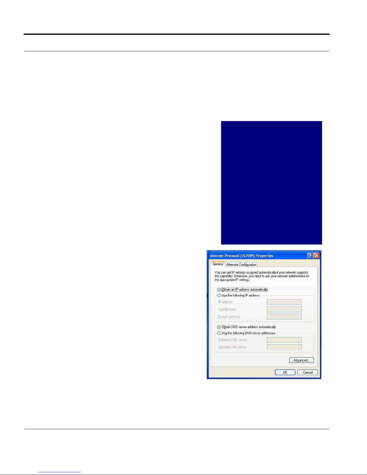
b. Windows XP follows a path like this:
28
Start menu -> Control Panel -> Network and
Internet Connections -> Network Connections -> Local Area Connection -> Properties
-> Internet Protocol [TCP/IP] -> Properties
Then go to Step 2.
Step 2. Select Obtain an IP address automati-
cally.
Step 3. Select Obtain DNS server address auto-
matically, if available.
Step 4. Remove any previously configured Gateways, if available.
Step 5. OK the settings. Restart if prompted.
Page 29
Set up the Motorola Netopia® Gateway
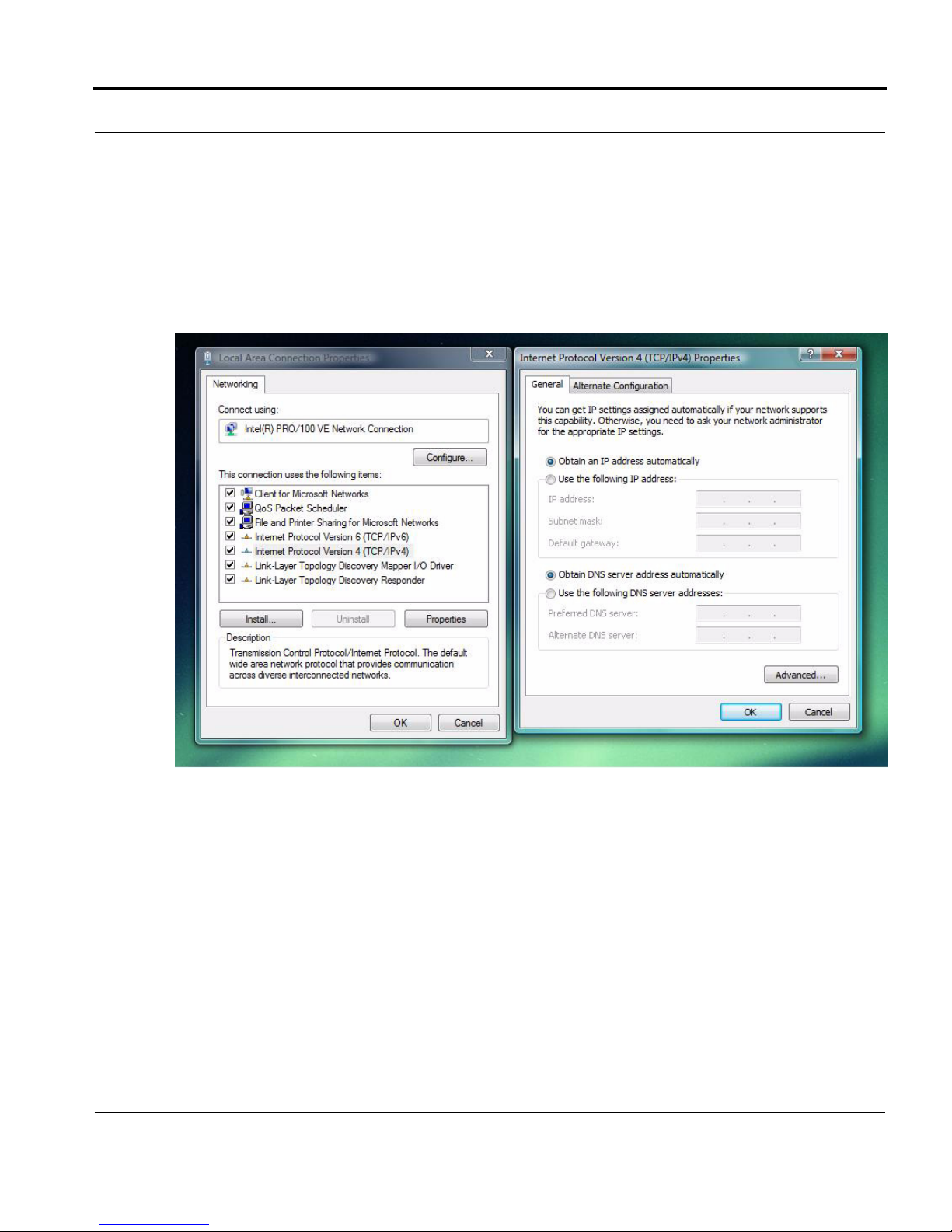
c. Windows Vista is set to obtain an IP address automatically by default. You may not need
to configure it at all.
To check, open the Networking Control Panel and select Internet Protocol Version 4
(TCP/IPv4). Click the Properties button.
The Internet Protocol Version 4 (TCP/IPv4) Properties window should appear as shown.
If not, select the radio buttons shown above, and click the OK button.
29
Page 30
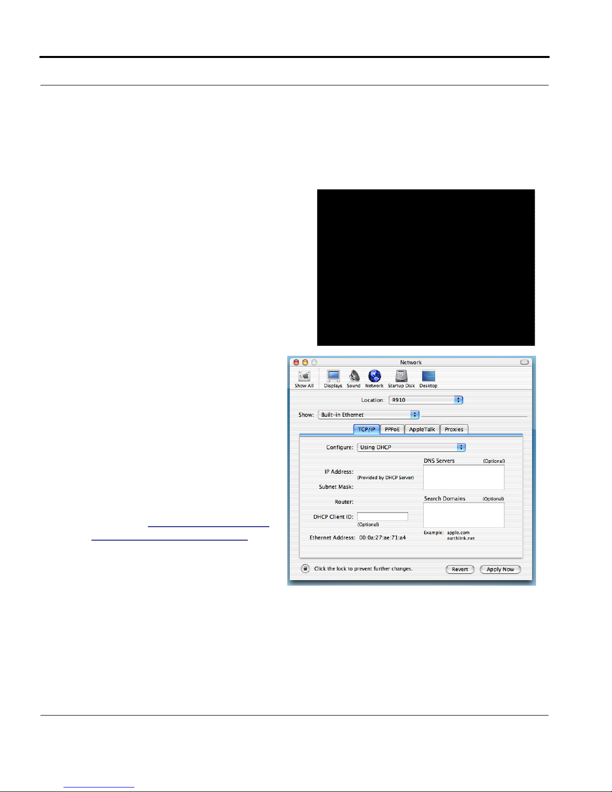
Macintosh MacOS 9 or higher or Mac OS X:
Step 1. Access the TCP/IP or Network control panel.
a. Mac OS 9 follows a path like this:
Apple Menu -> Control Panels -> TCP/IP
Control Panel
b. Mac OS X follows a path like this:
Apple Menu -> System Preferences -> Network
Then go to Step 2.
30
Step 2. Select Built-in Ethernet
Step 3. Select Configure Using DHCP
Step 4. Close and Save, if prompted.
Proceed to “Configure the Motorola
Netopia® Gateway” on page 31.
Page 31

Configure the Motorola Netopia® Gateway
Configure the Motorola Netopia® Gateway
1. Run your Web browser application, such as Firefox or Microsoft Internet Explorer,
from the computer connected to the Motorola Netopia® Gateway.
Enter http://192.168.0.1 in the URL Address text box. Press Enter or click Go.
The Admin Password page appears.
For security, you must create and enter an Administrative password for accessing the
Motorola Netopia® Gateway.
• The administrative User name is admin.
• The initial Password can be whatever you choose, from one to 32 characters long.
This user name and password are separate from the user name and password you will
use to access the Internet. You may change them later. You will be challenged for this
Admin username and password any time that you attempt to access the Motorola Netopia® Gateway’s configuration pages.
31
Page 32

When you connect to your Gateway as an Administrator, you enter “admin” as the User-
Name and the Password you just created.
The browser displays the Internet Login page.
2. Enter the User Name and Password supplied by your Internet Service Provider.
Click the
Connect button.
32
Page 33

Configure the Motorola Netopia® Gateway
Once you enter your User Name and Password here, you will no longer need to enter
them whenever you access the Internet. The Motorola Netopia® Gateway stores this
information and automatically connects you to the Internet.
3. Congratulations! Your installation is complete. You can now surf to your favorite Web
sites by typing an URL in your browser’s location box or by selecting one of your
favorite Internet bookmarks.
You can access the Gateway’s internal management pages at any time by entering
http://192.168.0.1 in your browser’s address field.
The Motorola Netopia® Gateway’s home page appears.
If you have any questions or encounter problems with your Motorola Netopia® Gateway,
refer to the detailed documentation on the Motorola Netopia® CD, or contact your ser vice
provider’s technical support helpdesk.
Answers to many frequently asked Motorola Netopia® modem questions are also available
on-line at: http://www.netopia.com/support.
33
Page 34

Motorola Netopia® Gateway Status Indicator
Lights
Colored LEDs on your Motorola Netopia® Gateway indicate the status of various port activity. Also, see “Basic Troubleshooting” on page 157 for more information.
Motorola Netopia® Gateway 3347-02 status indicator lights
Internet
DSL
34
LED Action
Power
Ethernet 1, 2, 3, 4
Wireless
DSL
Internet
Power
Green when power is on. Red when updating embedded
software, or for system failure.
Solid green when connected. Flash green when there is
activity on the LAN. Red when bad userid and password
are entered.
Flashes green when there is activity on the wireless
LAN.
Solid green when Internet connection is established.
Solid green when router is connected. Flashes green
when transmitting or receiving data.
Ethernet 1, 2, 3, 4
Wireless
Page 35

Accessing the Web User Interface
Accessing the Web User Interface
After you have performed the basic Quickstar t configuration, any time you log in to your
Motorola Netopia® Gateway you will access the Motorola Netopia® Gateway Home page.
You access the Home Page by typing
box.
The Basic Mode Home Page appears.
http://192.168.0.1 in your Web browser’s location
The links in the left-hand column on this page allow you to manage or configure several features of your Gateway. Each link is described in its own section.
35
Page 36

Links Bar
The Links Bar is the frame at the left-hand side of the page containing the major navigation links. These links are available
from almost every page, allowing you to move freely about the
site. The headings in the following table are hyperlinks. You can
click on any heading to read about that feature.
“Home” on page 37
“Wireless” on page 39
“Gaming” on page 58
“Advanced Setup” on page 65
“Status” on page 66
“Diagnostics” on page 71
“Help” on page 72
36
Page 37

Home
Home
Home Page Information
The Home page displays information about the following categories:
• Connection Information
• Router Information
• Local Network
Click the
mation. Help is available for every page in the Web interface.
Help link in the left-hand column of links to display a page of explanatory infor-
37
Page 38

Home Page Links
The links in the left-hand column of the Home page access a series of pages to allow you
to monitor, diagnose, and update your router. The following sections give descriptions of
these pages.
38
Page 39

Home
Link:
(supported models only)
When you click
Wireless
Wireless, the 3-D Reach Wireless configuration page appears.
Enable Wireless
The wireless function is not automatically enabled by default. If you check the Enable
Wireless checkbox, the Wireless Options are enabled, and the Gateway will provide or
broadcast its wireless LAN ser vices.
Wireless ID (SSID)
The Wireless ID is preset to a number unique to your unit. You can either leave it as is, or
change it by entering a freeform name of up to 32 characters, for example “Hercule’s Wireless LAN”. On client PCs’ software, this might also be called the Network Name. The Wireless ID is used to identify this particular wireless LAN. Depending on their operating
system or client wireless card, users must either:
• select from a list of available wireless LANs that appear in a scanned list on their client
39
Page 40

• or enter this name on their clients in order to join this wireless LAN.
Privacy
The pull-down menu for enabling Privacy offers four settings: WPA-802.1x, WPA-PSK,
WEP-Manual, and Off - No Privacy.
IT IS STRONGLY RECOMMENDED THAT YOU ENABLE SOME FORM OF PRIVACY
FOR THE SECURITY OF YOUR WIRELESS NETWORK.
See “Privacy” on page 44 for more information.
40
Page 41

Home
Advanced Configuration Options (optional)
When you click the Advanced Configuration Options button, the Advanced 802.11
Wireless screen appears. This screen varies its options depending on which form of wire-
less Privacy you have selected.
Operating Mode
The pull-down menu allows you to select and lock the Gateway into the wireless transmission mode you want. For compatibility with clients using 802.11b (up to 11 Mbps transmission) and 802.11g (up to 20+ Mbps), select Normal (802.11b + g). To limit your wireless
LAN to one mode or the other, select 802.11b Only, or 802.11g Only.
☛ NOTE:
If you choose to limit the operating mode to 802.11b or 802.11g only, clients
using the mode you excluded will not be able to connect.
41
Page 42

Default Channel
(1 through 11, for North America) on which the network will broadcast. This is a frequency
range within the 2.4Ghz band. Channel selection depends on government regulated radio
frequencies that vary from region to region. The widest range available is from 1 to 14.
Europe, France, Spain and Japan differ. Channel selection can have a significant impact on
performance, depending on other wireless activity close to this Router. Channel selection
is not necessary at the client computers; the clients will scan the available channels seeking access points using the same SSID as the client.
AutoChannel Setting
For 802.11G models, AutoChannel is a feature that allows the Motorola Netopia® Gateway
to determine the best channel to broadcast automatically.
Three settings are available from the pull-down menu: Off-Use default, At Startup, and
Continuous.
• Off-Use default: the Motorola Netopia® Gateway will use the configured default chan-
nel selected from the previous pull-down menu.
• At Startup – the default setting – causes the Motorola Netopia® Gateway at star tup to
briefly initialize on the default channel, then perform a full two- to three-second scan,
and switch to the best channel it can find, remaining on that channel until the next
reboot.
• Continuous performs the at-startup scan, and will continuously monitor the current
channel for any other Access Point beacons. If an Access Point beacon is detected on
the same channel, the Motorola Netopia® Gateway will initiate a three- to four-minute
scan of the channels, locate a better one, and switch. Once it has switched, it will
remain on this channel for at least 30 minutes before switching again if another Access
Point is detected.
Enable Closed System Mode
If enabled, Closed System Mode hides the wireless network from the scanning features of
wireless client computers. Unless both the wireless clients and the Router share the same
Wireless ID in Closed System mode, the Router’s wireless LAN will not appear as an available network when scanned for by wireless-enabled computers. Members of the Closed
System WLAN must log onto the Router’s wireless network with the identical SSID as that
configured in the router.
42
Page 43

Home
Closed System mode is an ideal way to increase wireless security and to prevent casual
detection by unwanted neighbors, office users, or malicious users such as hackers.
If you do not enable Closed System Mode, it is more convenient, but potentially less
secure, for clients to access your WLAN by scanning available access points. You must
decide based on your own network requirements.
About Closed System Mode and Wireless Encryption
Enabling Closed System Mode on your wireless Router provides another level of security,
since your wireless LAN will no longer appear as an available access point to client PCs
that are casually scanning for one.
Your own wireless network clients, however, must log into the wireless LAN by using the
exact SSID of the Motorola Netopia® Router.
In addition, if you have enabled WEP or WPA encryption on the Motorola Netopia® Router,
your network clients must also have WEP or WPA encryption enabled, and must have the
same WEP or WPA encryption key as the Motorola Netopia® Router.
Once the Motorola Netopia® Gateway is located by a client computer, by setting the client
to a matching SSID, the client can connect immediately if WEP or WPA is not enabled. If
WEP or WPA is enabled then the client must also have WEP or WPA enabled and a matching
WEP or WPA key.
Wireless client cards from dif ferent manufacturers and dif ferent operating systems accomplish connecting to a wireless LAN and enabling WEP or WPA in a variety of ways. Consult
the documentation for your particular wireless card and/or operating system.
Block Wireless Bridging
Check the checkbox to block wireless clients from communicating with other wireless clients on the LAN side of the Gateway.
43
Page 44

Privacy
• OFF - No Privacy: This mode disables privacy on your network, allowing any wireless
users to connect to your wireless LAN. Use this option if you are using alternative security measures such as VPN tunnels, or if your network is for public use.
• WEP - Manual: WEP Security is a Privacy option that is based on encryption between
the Router and any PCs (“clients”) you have with wireless cards. If you are not using
WPA-PSK Privacy, you can use WEP Encryption instead. For this encr yption to work, both
your Router and each client must share the same Wireless ID, and both must be using
the same encryption keys.
• WPA-802.1x provides RADIUS server authentication support. See RADIUS Server
authentication below.
• WPA-PSK provides Wireless Protected Access, the most secure option for your wire-
less network. See “
tection and access control.
Be sure that your Wi-Fi client adapter supports this option. Not all Wi-Fi clients support
WPA-PSK.
WPA-PSK” on page 47. This mechanism provides the best data pro-
44
Page 45

Home
RADIUS Server authentication
RADIUS servers allow external authentication of users by means of a remote authentication database. The remote authentication database is maintained by a Remote Authentication Dial-In User Service (RADIUS) server. In conjunction with Wireless User Authentication,
you can use a RADIUS server database to authenticate users seeking access to the wireless services, as well as the authorized user list maintained locally within the Gateway.
If you select WPA-802.1x, the screen expands.
Click the
The Configure RADIUS Server screen appears.
Configure RADIUS Server button.
45
Page 46

Enter your RADIUS Server information in the appropriate fields:
• RADIUS Server Addr/Name: The default RADIUS server name or IP address that you
want to use.
• RADIUS Server Secret: The RADIUS secret key used by this server. The shared secret
should have the same characteristics as a normal password.
• Alt RADIUS Server Addr/Name: An alternate RADIUS server name or IP address, if
available.
• Alt RADIUS Server Secret: The RADIUS secret key used by this alternate ser ver. The
shared secret should have the same characteristics as a normal password.
• RADIUS Server Port: The port on which the RADIUS server is listening, typically, the
default 1812.
Click the Save Changes button.
46
Page 47

Home
WPA-PSK
One of the easiest ways to enable Privacy on your Wireless network is by selecting
WPA-PSK (Wi-Fi Protected Access) from the pull-down menu.
The screen expands to allow you to enter a Pre Shared Key. The key can be between 8
and 63 characters, but for best security it should be at least 20 characters. When you have
entered your key, click the
Save Changes button.
47
Page 48

WEP-Manual
Alternatively, you can enable WEP (Wired Equivalent Privacy) encryption by selecting
WEP-Manual from the Privacy pull-down menu.
You can provide a level of data security by enabling WEP (Wired Equivalent Privacy) for
encryption of network data. You can enable 40-, 128-, or 256-bit WEP Encr yption (depending on the capability of your client wireless card) for IP traffic on your LAN.
48
Page 49

Home
WEP - Manual allows you to enter your own encryption keys manually. This is a difficult
process, but only needs to be done once. Avoid the temptation to enter all the same characters.
Encryption Key Size #1 – #4: Selects the length of each encryption key. The longer the
key, the stronger the encr yption and the more dif ficult it is to break the encr yption.
Encryption Key #1 – #4: The encryption keys. You enter keys using hexadecimal digits.
For 40/64bit encryption, you need ten digits; 26 digits for 128bit, and 58 digits for 256bit
WEP. Hexadecimal characters are 0 – 9, and a – f.
Examples:
• 40bit: 02468ACE02
• 128bit: 0123456789ABCDEF0123456789
• 256bit: 592CA140F0A238B0C61AE162F592CA140F0A238B0C61AE162F21A09C
Use WEP encryption key (1 – 4) #: Specifies which key the Gateway will use to encrypt
transmitted traffic. The default is key #1.
Click the click Save Changes button.
Any WEP-enabled client must have an identical key of the same length as the Router, in
order to successfully receive and decr ypt the traffic. Similarly, the client also has a
‘default’ key that it uses to encrypt its transmissions. In order for the Router to receive the
client’s data, it must likewise have the identical key of the same length.
49
Page 50

Enable Multiple Wireless IDs
This feature allows you to add additional network identifiers (SSIDs or Network Names) for
your wireless network. To enable Multiple Wireless IDs, click the button.
The Enable Multiple Wireless IDs screen appears to allow you to add up to three addi-
tional Wireless IDs.
50
When the Multiple Wireless SSIDs screen appears, check the Enable SSID checkbox for
each SSID you want to enable.
The screen expands to allow you to name each additional Wireless ID, and specify a Privacy mode for each one.
Page 51

Home
Privacy modes available from the pull-down menu for the multiple SSIDs are: WPA-PSK,
WPA-802.1x, or Off-No Privacy.
These additional Wireless IDs are “Closed System Mode” Wireless IDs (see below) that
will not be shown by a client scan, and therefore must be manually configured at the client.
In addition, wireless bridging between clients is disabled for all members of these additional network IDs.
Click the
Save Changes button. The Gateway will prompt you to restart it.
51
Page 52

Click the Yes button, and the Gateway will restar t with your new settings.
☛ NOTES:
The Gateway supports up to 4 different SSIDs:
• One SSID is broadcast by default and has wireless bridging enabled by
default.
• Three additional SSIDs are in “Closed System Mode” and have wireless
bridging disabled.
• These network IDs cannot be configured separately in terms of MAC
Address filtering.
• You can configure privacy on one SSID and disable it on another SSID.
52
Page 53

Home
WiFi Multimedia
WiFi Multimedia is an advanced feature that allows you to prioritize various types of data
travelling over the wireless network. Certain types of data that are sensitive to delays,
such as voice or video, must be prioritized ahead of other, less delay-sensitive types, such
as email.
WiFi Multimedia currently implements wireless Quality of Service (QoS) by transmitting
data depending on Diffserv priority settings. These priorities are mapped into four Access
Categories (AC), in increasing order of priority:
• Background (BK),
• Best Effort (BE),
• Video (VI), and
• Voice (VO).
It requires WiFi Multimedia (WMM)-capable clients, usually a separate feature enabled at
the client network settings, and client PC software that makes use of Differentiated Services (Diffserv). Refer to your operating system instructions for enabling Diffserv QoS.
When you click the WiFi Multimedia button the WiFi Multimedia page appears.
To enable the WiFi Multimedia custom settings, select Diffserv from the pull-down menu.
53
Page 54

The screen expands.
54
Router EDCA Parameters (Enhanced Distributed Channel Access) govern wireless data
from your Gateway to the client; Client EDCA Parameters govern wireless data from the
client to your Gateway.
☛ NOTE:
It is not recommended that you modify these settings without direct knowledge or instructions to do so. Modifying these settings inappropriately could
seriously degrade network performance.
• AIFs: (Arbitration Interframe Spacing) the wait time in milliseconds for data frames.
• cwMin: (Minimum Contention Window) upper limit in milliseconds of the range for deter-
mining initial random backoff. The value you choose must be lower than cwMax.
Page 55

Home
• cwMax: (Maximum Contention Window) upper limit in milliseconds of the range of
determining final random backoff. The value you choose must be higher than cwMin.
• TXOP Limit: Time interval in microseconds that clients may initiate transmissions.
(When Operating Mode is B-only, default values are used and this field is not config-
urable.)
Click the Save Changes button.
Wireless MAC Authorization (optional)
MAC Authorization allows you to specify which client PCs are allowed to join the wireless
LAN by unique hardware (MAC) address. To enable this feature, click the
Access by MAC Address button. The MAC Authorization screen appears.
Limit Wireless
Select
Enabled from the pull-down menu.
55
Page 56

The screen expands to permit you to add MAC addresses.
56
Click the
Once it is enabled, only entered MAC addresses that have been set to
accepted onto the wireless LAN. All unlisted addresses will be blocked, in addition to the
listed addresses with Allow disabled.
Add button.
Allow
will be
Page 57

Home
Click the Submit button.
When you are finished adding MAC addresses click the
be returned to the 802.11 Wireless page. You can Add, Edit, or Delete any of your entries
later by returning to this page.
Save Changes button. You will
57
Page 58

Link:
When you click Gaming, the NAT (Games and Other Services) page appears.
NAT (Games and Other Services) allows you to host internet applications when NAT is
enabled. You can host dif ferent games and software on different PCs. If you uncheck the
Enable NAT checkbox, the rest of the information on the page is hidden.
From the Service Name pull-down menu, you can select any of a large number of predefined games and software. (See “Supported Games and Software” on page 59.)
Gaming
58
1. Once you choose a software service or game, click Enable.
The Enable Service screen appears.
Select Host Device specifies the machine on which the selected software is hosted.
2. Select a PC to host the software from the Select Host Device pull-down
menu and click Enab
le.
Page 59

Home
Each time you enable a software service or game your entry will be added to the list of
Service Names displayed on the NAT Configuration page.
To remove a game or software from the hosted list, choose the game or software you want
to remove and click the
Supported Games and Software
Age of Empires, v.1.0 Age of Empires: The Rise of
Asheron's Call Baldur's Gate Battlefield Communicator
Buddy Phone Calista IP Phone CART Precision Racing, v 1.0
Citrix Metaframe/ICA Client Close Combat for Windows 1.0 Close Combat: A Bridge Too
Disable button.
Age of Wonders
Rome, v.1.0
Far, v 2.0
59
Page 60

Close Combat III: The Russian
Front, v 1.0
Dark Reign Delta Force (Client and Server) Delta Force 2
Diablo II Server Dialpad DNS Server
Dune 2000 eDonkey 2000 eMule
F-16, Mig 29 F-22, Lightning 3 Fighter Ace II
FTP GNUtella H.323 compliant (Netmeeting,
Half Life Hellbender for Windows, v 1.0 Heretic II
Hexen II Hotline Server HTTP
HTTPS ICQ 2001b ICQ Old
IMAP Client IMAP Client v.3 Internet Phone
IPSec IPSec IKE Jedi Knight II: Jedi Outcast
Kali KazaA LimeWire
Links LS 2000 Mech Warrior 3 Mech Warrior 4: Vengeance
Combat Flight Sim: WWII
Europe Series, v 1.0
Combat Flight Sim 2: WWII
Pacific Thr, v 1.0
CUSeeME)
60
Medal of Honor Allied Assault Microsoft Flight Simulator 98 Microsoft Flight Simulator
2000
Microsoft Golf 1998 Edition, v
1.0
Midtown Madness, v 1.0 Monster Truck Madness, v 1.0 Monster Truck Madness 2, v
Motocross Madness 2, v 2.0 Motocross Madness, v 1.0 MSN Game Zone
MSN Game Zone (DX7 an 8
Play)
Net2Phone NNTP Operation FlashPoint
Outlaws pcAnywhere (incoming) POP-3
PPTP Quake II Quake III
Rainbow Six RealAudio Return to Castle Wolfenstein
Microsoft Golf 1999 Edition Microsoft Golf 2001 Edition
2.0
Need for Speed 3, Hot Pursuit Need for Speed, Porsche
Page 61

Home
Roger Wilco Rogue Spear ShoutCast Server
SMTP SNMP SSH server
StarCraft Starfleet Command StarLancer, v 1.0
Telnet TFTP Tiberian Sun: Command and
Conquer
Timbuktu Total Annihilation Ultima Online
Unreal Tournament Server Urban Assault, v 1.0 VNC, Virtual Network Comput-
ing
Westwood Online, Command
and Conquer
Yahoo Messenger Chat Yahoo Messenger Phone ZNES
Win2000 Terminal Ser ver XBox Live Games
Define Custom Service
To configure a Custom Ser vice, choose whether to use Por t For warding or Trigger Ports.
• Port Forwarding forwards a range of WAN ports to an IP address on the LAN.
• Trigger Ports forwards a range of ports to an IP address on the LAN only after specific
outbound traffic “triggers” the feature.
Click the Next button.
If you chose Port Forwarding, the Port Range entry screen appears.
61
Page 62

Port Forwarding forwards a range of WAN ports to an IP address on the LAN. Enter the following information:
• Service Name: A unique identifier for the Custom Service.
• Global Port Range: Range of ports on which incoming traffic will be received.
• Base Host Port: The port number at the start of the port range your Router should use
when forwarding traffic of the specified type(s) to the internal IP address.
• Protocol: Protocol type of Internet traffic, TCP or UDP.
Click the Next button.
If you chose Trigger Ports, the Trigger Ports entry screen appears.
62
Page 63

Home
Trigger Ports for wards a range of ports to an IP address on the LAN only after specific outbound traffic “triggers” the feature. Enter the following information:
• Service Name: A unique identifier for the Custom Service.
• Global Port Range: Range of ports on which incoming traffic will be received.
• Local Trigger Port: Port number of the type of outbound traffic that needs to happen
(will be the trigger) to then allow the configured ports for inbound traffic.
Example: Set the trigger port to 21 and configure a range of 25 – 110. You would need
to do an outbound ftp before you were able to do an inbound smtp.
Click the
Next button.
Static NAT
This feature allows you to:
• Direct your Router to forward all externally initiated IP traf fic (TCP and UDP protocols
only) to a default host on the LAN.
• Enable it for certain situations:
– Where you cannot anticipate what port number or packet protocol an in-bound application might use. For example, some network games select arbitrary port numbers
when a connection is opened.
– When you want all unsolicited traffic to go to a specific LAN host.
63
Page 64

This feature allows you to direct unsolicited or non-specific traffic to a designated LAN station. With NAT “On” in the Router, these packets normally would be discarded.
For instance, this could be application traffic where you don’t know (in advance) the port or
protocol that will be used. Some game applications fit this profile.
From the pull-down menu, select the address of the PC that you want to be your default
NAT destination.
Click the
Next button, and your choice will be so designated.
64
Page 65

Home
Link:
Advanced Setup allows you to configure a wide variety of specific Router and networking
settings. Advanced Setup is for advanced users and system administrators, and most
users will not need to modify these settings. If you need to enter Advanced Setup, and
click the
Advanced Setup
Advanced Setup link, the Advanced Setup Home page displays.
For more information, see “
Advanced Setup” on page 73.
65
Page 66

Link:
When you click the Status link, the Links Bar expands to display nine statistical sub-headings.
Status
These screens will vary depending on your Gateway’s model and traffic
activity.
•“DSL” on page 66
•“ATM” on page 67
•“Ethernet (supported models only)” on page 67
•“IP” on page 67
•“LAN” on page 68
•“USB (supported models only)” on page 68
•“Wireless (supported models only)” on page 69
•“Logs” on page 69
•“User List” on page 70
66
DSL
When you click DSL, the DSL Statistics page appears.
The DSL Statistics page displays information about the Router's WAN connection to the
Internet.
• Line State: May be Up (connected) or Down (disconnected).
• Modulation: Method of regulating the DSL signal. DMT (Discrete MultiTone) allows con-
nections to work better when certain radio transmitters are present.
• Data Path: Type of path used by the device's processor.
Downstream and Upstream statistics
• Max Allowed Speed (kbps): Your maximum speeds for downloading (receiving) and
uploading (sending) data on the DSL line, in kilobits per second.
Page 67

Home
• SN Margin (db): Signal to noise margin, in decibels. Reflects the amount of unwanted
“noise” on the DSL line.
• Line Attenuation: Amount of reduction in signal strength on the DSL line, in decibels.
• CRC Errors: Number of times data packets have had to be resent due to errors in
transmission or reception.
ATM
When you click ATM, the ATM Statistics page appears.
The ATM Statistics page displays detailed statistics about the upstream and downstream
data traffic handled by your Router. Displays the Virtual Circuit (VPI/VCI) settings as well as
information about your PPPoE session if operating in PPPoE mode. This information is useful for troubleshooting and when seeking technical support.
Ethernet (supported models only)
When you click Ethernet, the Ethernet Statistics page appears.
The Ethernet Statistics page:
• displays your Router's unique hardware (MAC) address.
• displays detailed statistics about your LAN data traffic, upstream and downstream.
IP
When you click IP, the IP Statistics page appears. The IP Statistics page displays the IP
interfaces and routing table information about your network.
General
• IP WAN Address: The public IP address of your Router, whether dynamically or stati-
cally assigned.
• IP Gateway: Your ISP's gateway router IP address
• Primary DNS: The IP address of the Primary Domain Name Ser ver
• Primary DNS name: The name of the Primary Domain Name Server
• Secondary DNS: The IP address of the backup Domain Name Server (if any)
• Secondary DNS name: The name of the backup Domain Name Server (if any)
67
Page 68

IP interfaces
• Address: Your Router's IP address as seen from your internal network (LAN), and from
the public Internet (WAN)
• Netmask: The subnet mask for the respective IP interfaces (LAN and WAN)
• Name: The name of each IP interface (example:Eth0, WAN1)
Network Routing Table and Host Routing Table
The Routing tables display all of the IP routes currently known to your Router.
LAN
When you click LAN, the LAN Statistics page appears.
The LAN Statistics page displays detailed information about your LAN IP configuration and
names and IP addresses of devices on your LAN.
• Router IP Address: The IP address of your Router as seen from the LAN
• DHCP Netmask: Subnet mask of your LAN
• DHCP Start Address: First IP address in the range being served to your LAN by the
Router's DHCP server
• DHCP End Address: Last IP address in the range being served to your LAN by the
Router's DHCP server
• DHCP Server Status: May be On or Off
• DNS Server: The IP address of the default DNS server
68
Devices on LAN
Displays the IP Address, MAC (hardware) Address, and network Name for each device on
your LAN connected to the Router.
USB (supported models only)
When you click USB, the USB Statistics page appears.
The USB Statistics page:
• displays your Router's unique hardware (MAC) address.
• displays detailed statistics about your LAN data traffic, upstream and downstream.
Page 69

Home
Wireless (supported models only)
When you click Wireless, the Wireless Statistics page appears.
The Wireless Statistics page:
• displays your Router's unique hardware Wireless (MAC) address.
• displays detailed statistics about your Wireless LAN data traffic, upstream and down-
stream.
Logs
When you click Logs, the Logs page appears.
Select a log from the pull-down menu (the pull-down menu is available from ever y Log
page):
• All: Displays the entire system log.
• Connection: Displays events logged for the WAN connection.
• System: Displays events logged for the Router system configuration.
The CURRENT Router STATUS is displayed for all logs.
• To clear the individual logs, click the Clear Log button for that page.
• To clear all the logs, click the Clear All Logs button on the main Logs page.
• You can save logs to a text (.CTXT) file by clicking the Save to File button. This will
download the file to your browser’s default download location on your hard drive. The
file can be opened with your favorite text editor.
☛ Note:
69
Page 70

Some browsers, such as Internet Explorer for Windows XP, require that you
specify the Motorola Netopia® Gateway’s URL as a “Trusted site” in “Internet
Options: Security”.
User List
When you click User List, the User List Statistics page appears.
The User List Statistics page:
• displays Ethernet Users’ PC Name, IP Address, and MAC Address.
• displays Wireless SSID Users’ PC Name, IP Address, and MAC Address.
If you have multiple SSIDs defined (see “
Wireless SSID users are displayed by their respective SSID.
Enable Multiple Wireless IDs” on page 50),
70
Page 71

Home
Link:
This automated multi-layer test examines the functionality of the Router from the physical
connections to the data traffic being sent by users through the Router.
Diagnostics
You enter a web address, such as tftp.netopia.com, or an IP address in the Web Address
field and click the
are generated.
This sequence of tests takes approximately one minute to generate results. Please wait for
the test to run to completion.
Each test generates one of the following result codes:
Test button. Results will be displayed in the Progress Window as they
Result Meaning
* PASS: The test was successful.
* FAIL: The test was unsuccessful.
* SKIPPED: The test was skipped because a test on which it depended failed.
* PENDING: The test timed out without producing a result. Try running Diagnostics again.
* WARNING: The test was unsuccessful. The Service Provider equipment your Router con-
nects to may not support this test.
71
Page 72

Link:
When you click the Help link in the left-hand column of links a page of explanatory information displays. Help (in English only) is available for every page in the Web interface.
Here is an example from the Home page:
Help
72
Page 73

Access the Expert Web Interface
CHAPTER 3 Advanced Setup
Using the Web-based user interface for the Motorola Netopia® 2200 and 3300-series
Gateway you can configure, troubleshoot, and monitor the status of your Gateway.
Access the Expert Web Interface
Open the Web Connection
Once your Gateway is powered up, you can use any recent version of the best-known web
browsers such as Netscape Navigator or Microsoft Internet Explorer from any LAN-attached
PC or workstation. The procedure is:
1. Enter the name or IP address of your Netopia Gateway in the Web browser's window
and press Return.
For example, you would enter http://192.168.0.1
2. If an administrator or user password has been assigned to the Netopia Gateway,
enter Admin or User as the username and the appropriate password and click OK.
The Basic Mode Home Page opens.
.
73
Page 74

3. Click on the Advanced Setup link in the left-hand column of links.
The Home Page opens in Advanced Setup.
74
Page 75

Access the Expert Web Interface
Home Page - Advanced Setup
The Advanced Setup Home Page is the summary page for your Motorola Netopia® Gateway. The links bar at the left provides links to controlling, configuring, and monitoring
pages. Critical configuration and operational status is displayed in the center section.
75
Page 76

Home Page - Information
The Home Page contains a summary of the Gateway’s configuration settings and status.
Summary Information
Field Status and/or Description
Connection Information
DSL/WAN Status Wide Area Network may be Waiting for DSL (or other waiting status), Up or Down
Connection Up or Down
User Name Your ISP-assigned Username
IP Address IP address assigned to the WAN port.
IP Gateway The IP address of the gateway to which the connection defaults. If doing DHCP, this
info will be acquired. If doing PPP, this info will be negotiated.
Primary and
Secondary DNS
Server
Speed Your upstream and downstream data rates
Line Attenuation amount of attenuation on your phone lines.
Restart Connec-
tion button
Connect button allows you to reconnect using a different User Name and Password. This button is
Disconnect button allows you to disconnect your current connection. This button is only available if a
Address(es) of your ISP's Domain Name Server(s).
allows you to attempt to reconnect using the same login credentials as your current
connection.
only available if you are not connected.
connection is established.
76
Router Information
Router Name and
Model
Serial Number Your Router's unique serial number. Usually also printed on the Router's label.
MAC Address Your Router's unique hardware address
Software Version The version of embedded operating system software currently running on the Gate-
Warranty Date Original date when your Gateway is first connected and gets the time via the network,
Your Router's manufacturing information
way.
for warranty purposes.
Local Network
IP Address The IP address of your Router as seen from your internal LAN
Ethernet Status of your Ethernet network connection (if supported). Connected or Not Con-
nected.
USB Status of your USB network connection (if supported). Connected or Not Connected.
Page 77

Links Bar
Links Bar
The Links Bar is the frame at the left-hand side of the page
containing the major navigation links. These links are available
from every page, allowing you to move freely about the site.
The headings in the following table are hyperlinks. You can
click on any heading to read about that feature.
This chapter covers the following:
Advanced Setup
Configure Connection DHCP Server IP Passthrough NAT IPSec
Router Password Time Zone VLAN Wireless
Status DSL ATM Ethernet IP LAN
USB Wireless Logs User List
Diagnostics
Update Router
Reset Router
Restart Router
Basic Mode
Help
Note: Ethernet, Wireless, and USB links are only available on supported models.
77
Page 78

Link:
When you click Configure, the Links bar expands to display the configuration options available.
Advanced options are intended for experienced users and administrators. Exercise great caution when making any changes to
Advanced Configuration options.
Configure
• “Connection” on page 79
• “DHCP Server” on page 82
• “IP Passthrough” on page 85
• “NAT” on page 87
• “IPSec” on page 94
• “Router Password” on page 104
• “Time Zone” on page 105
• “VLAN” on page 106
• “Wireless” on page 125
78
Page 79

Links Bar
Link:
When you click Connection, the Connection Configuration page appears.
Note: The appearance of this page will vary based on the model and WAN connection you
have.
Connection
Here you can set up or change the way you connect to your ISP. You should only change
these settings at your ISP's direction, or by agreement with your ISP.
79
Page 80

• VPI/VCI: These values depend on the way your ISP's equipment is configured. The
default setting is 8/35. With this setting, the router will match the settings your ISP is
using, with no input on your part. You probably would not need to change this.
• Protocol: The authentication and encapsulation protocol is determined by your ISP,
often by the type of account that you have signed up for. Options here are PPPOE LLC,
PPPOE VCMUX, ETHER LLC, IP LLC, PPPOA LLC, and PPPOA VCMUX.
• Bridging: Your Router can be turned into a simple bridge, if desired. However, it will no
longer provide routing or security features in this mode.
• Concurrent Bridging/Routing: Your Router can bridge or route traffic, depending on
the IP addresses, at the same time. When this mode is enabled, the Router will also
bridge traffic from the LAN if it has a valid LAN-side address.
• PPPoE/PPPoA/DHCP Autosensing: The pull-down menu allows you to select an
autosensing feature, or to disable it. Selecting between PPPoE/DHCP or PPPoE/PPPoA
enables automatic sensing of your WAN connection type. If you select PPPoE/DHCP,
the gateway attempts to connect using PPPoE first. If the Gateway fails to connect after
60 seconds, it switches to DHCP. As soon as it can connect via DHCP, the Gateway
chooses and sets DHCP as its default. Otherwise, after attempting to connect via DHCP
for 60 seconds, the Gateway switches back to PPPoE. The Gateway will continue to
switch back and forth in this manner until it successfully connects. Similarly, selecting
PPPoE/PPPoA causes the Gateway to attempt to connect by trying these protocols in
parallel, and using the first one that is successful. If you choose to disable the feature,
select Off.
• User Name and Password: Provided by your ISP.
• Confirm Password: Repeat your Password entry for confirmation
• Select the IP Type:
Dynamic IP - DHCP (Default) –
Single Static IP Address –
Block of Static IP Addresses (Unnumbered Mode) –
• Static IP Address: Your ser vice provider may tell you that the WAN IP Address for your
Router is static. If so, enter the IP Address from your ser vice provider in this field.
• IP Gateway: The IP Address of the default gateway, or peer address if using PPP. This
is normally set to 0.0.0.0 for PPP connections.
• Primary DNS Server: The IP Address of the Primar y Domain Name Ser ver
• Secondary DNS Server: The IP Address of the backup Domain Name Ser ver
• Connection Type: If using PPPoE, this is a choice to have either an uninterrupted con-
nection or an as-needed connection. The type of service you have signed up for with
your ISP. Options are On-Demand, Always ON, and Manual.
80
Page 81

Links Bar
Always On: This setting provides convenience, but it leaves your network permanently
connected to the Internet.
On-Demand: Furnishes almost all the benefits of an Always On connection, but has
additional security benefits:
Your network cannot be attacked when it is not connected.
Your network may change address with each connection, making it more difficult to
attack.
Manual: This setting disables automatic connection attempts. The user must bring the
connection up and down via the Connect/Disconnect buttons.
• User Inactivity Timeout: For On-Demand connections only, you can specify the time in
seconds before disconnection if there is no data passing to or from the Internet.
• UPnP: Universal Plug and Play (UPnP™) is a set of protocols that allows a PC to auto-
matically discover other UPnP devices (anything from an internet gateway device to a
light switch), retrieve an XML description of the device and its services, control the
device, and subscribe to real-time event notification. By default, UPnP is enabled on the
Motorola Netopia® Gateway.
For Windows XP users, the automatic discovery feature places an icon representing the
Motorola Netopia® Gateway automatically in the “My Network Places” folder. Doubleclicking this icon opens the Gateway’s web UI.
PCs using UPnP can retrieve the Gateway’s WAN IP address, and automatically create
NAT port maps. This means that applications that suppor t UPnP, and are used with a
UPnP-enabled Motorola Netopia® Gateway, will not need application layer gateway support on the Motorola Netopia® Gateway to work through NAT.
You can disable UPnP, if you are not using any UPnP devices or applications. Uncheck
the UPnP Enabled checkbox.
When all of your entries are made, click the Sa
ve and Restart Connection button.
81
Page 82

Link:
When you click DHCP Server, the DHCP Server Configuration page appears.
DHCP Server
This feature simplifies network administration because the Router maintains a list of IP
address assignments. Additional computers can be added to your LAN without the hassle
of configuring an IP address. This is the default mode for your Router.
The Server configuration determines the functionality of your DHCP Settings. This functionality enables the Router to assign your LAN computer(s) a “private” IP address and other
parameters that allow network communication.
• Router IP Address: Specifies the IP address of the Router itself.
82
Page 83

Links Bar
• Subnet Mask: Specifies the subnet mask of the Router itself. Defaults to the common
Class C subnet.
• DHCP Start Address: Specifies the first address in the DHCP address range. You can
reserve a sequence of up to 253 IP addresses (including up to 64 IP addresses for
wireless clients) within a subnet, beginning with the specified address, for dynamic
assignment.
• DHCP End Address: Specifies the last address in the DHCP address range.
• DHCP Lease: Specifies the default length for DHCP leases issued by the Router. Enter
lease time in dd:hh:mm:ss (days/hours/minutes/seconds) format.
• DHCP Server Enable: Uncheck this setting if you already have a DHCP server on your
LAN. This enables the DHCP server in this Router.
Additional IP Subnets
The Additional IP Subnets screen allows you to configure up to seven secondar y subnets
and their DHCP ranges, by entering IP address/subnet mask pairs:
☛ Note:
You need not use this screen if you have only a single Ethernet IP subnet.
This screen displays seven rows of editable columns. All seven row labels are always visible, regardless of the number of subnets configured.
• To add an IP subnet, select one of the rows, and click the Edit button.
83
Page 84

Check the Enabled checkbox
and click the
The screen expands to
allow you to enter subnet
information.
If DHCP Server (see
below) is not enabled, the
DHCP Start Address and
DHCP End Address fields
do not appear.
Enter the Router’s IP
address on the subnet in
the IP Address field and
the subnet mask for the
subnet in the Netmask
field.
Enter the DHCP Start Address and End Address of the subnet range in their respective fields.
Ranges cannot overlap and there may be only one range per subnet.
Submit button.
• Click the Submit button.
• When you are finished adding subnets, click the Save Changes button, and when
prompted, restar t the Router.
To delete a configured subnet, set both the IP address and subnet mask values to 0.0.0.0,
either explicitly or by clearing each field and clicking the Submit button to commit the
change.
☛ NOTE:
All additional DHCP ranges use the global lease period value. See page 82.
If you make any changes, click the Sa
84
ve Changes button.
Page 85

Links Bar
Link:
When you click IP Passthrough, the IP Passthrough Configuration page appears.
IP Passthrough
The IP passthrough feature allows a single PC on the LAN to have the Router’s public
address assigned to it. It also provides PAT (NAPT) via the same public IP address for all
other hosts on the private LAN subnet. Using IP passthrough:
• The public WAN IP is used to provide IP address translation for private LAN computers.
• The public WAN IP is assigned and reused on a LAN computer.
• DHCP address serving can automatically serve the WAN IP address to a LAN computer.
When DHCP is used for addressing the designated passthrough PC, the acquired or
configured WAN address is passed to DHCP, which will dynamically configure a singleservable-address subnet, and reser ve the address for the configured PC’s MAC
address. This dynamic subnet configuration is based on the local and remote WAN
85
Page 86

address and subnet mask. If the WAN interface does not have a suitable subnet mask
that is usable, for example when using PPP or PPPoE, the DHCP subnet configuration
will default to a class C subnet mask.
1. Select either User Configured PC or an IP address displayed in the selec-
tion window (these are the IP addresses currently being served to computers on your LAN.)
If you select “User Configured PC”, you must then configure a local PC to have the public WAN IP address.
2. Click Enable.
You will be reminded to restart the Router.
3. Click the Restart Router link and confirm the restart when prompted.
Once configured, the passthrough host's DHCP leases will be shor tened to two minutes.
This allows for timely updates of the host's IP address, which will be a private IP address
before the WAN connection is established. After the WAN connection is established and
has an address, the passthrough host can renew its DHCP address binding to acquire the
WAN IP address.
A restriction
Since both the Router and the passthrough host will use the same IP address, new sessions that conflict with existing sessions will be rejected by the Router. For example, suppose you are a teleworker using an IPSec tunnel from the Router and from the passthrough
host. Both tunnels go to the same remote endpoint, such as the VPN access concentrator
at your employer’s office. In this case, the first one to start the IPSec traffic will be
allowed; the second one – since, from the WAN, it's indistinguishable – will fail.
86
Page 87

Links Bar
Link:
When you click NAT, the NAT (Games and Other Services) page appears.
NAT (Games and Other Services) allows you to host internet applications when NAT is
enabled. You can host dif ferent games and software on different PCs. If you uncheck the
Enable NAT checkbox, the rest of the information on the page is hidden.
From the Service Name pull-down menu, you can select any of a large number of predefined games and software. (See “Supported Games and Software” on page 89.)
NAT
1. Once you choose a software service or game, click Enable.
The Enable Service screen appears.
Select Host Device specifies the machine on which the selected software is hosted.
87
Page 88

2. Select a PC to host the software from the Select Host Device pull-down
menu and click
Enable.
Each time you enable a software service or game your entry will be added to the list of
Service Names displayed on the NAT Configuration page.
To remove a game or software from the hosted list, choose the game or software you want
to remove and click the Disab
88
le button.
Page 89

Links Bar
Supported Games and Software
Age of Empires, v.1.0 Age of Empires: The Rise of
Rome, v.1.0
Asheron's Call Baldur's Gate Battlefield Communicator
Buddy Phone Calista IP Phone CART Precision Racing, v 1.0
Citrix Metaframe/ICA Client Close Combat for Windows 1.0 Close Combat: A Bridge Too
Close Combat III: The Russian
Front, v 1.0
Dark Reign Delta Force (Client and Server) Delta Force 2
Diablo II Server Dialpad DNS Server
Dune 2000 eDonkey 2000 eMule
F-16, Mig 29 F-22, Lightning 3 Fighter Ace II
FTP GNUtella H.323 compliant (Netmeeting,
Half Life Hellbender for Windows, v 1.0 Heretic II
Hexen II Hotline Server HTTP
Combat Flight Sim: WWII
Europe Series, v 1.0
Age of Wonders
Far, v 2.0
Combat Flight Sim 2: WWII
Pacific Thr, v 1.0
CUSeeME)
HTTPS ICQ 2001b ICQ Old
IMAP Client IMAP Client v.3 Internet Phone
IPSec IPSec IKE Jedi Knight II: Jedi Outcast
Kali KazaA LimeWire
Links LS 2000 Mech Warrior 3 Mech Warrior 4: Vengeance
Medal of Honor Allied Assault Microsoft Flight Simulator 98 Microsoft Flight Simulator
2000
Microsoft Golf 1998 Edition, v
1.0
Midtown Madness, v 1.0 Monster Truck Madness, v 1.0 Monster Truck Madness 2, v
Microsoft Golf 1999 Edition Microsoft Golf 2001 Edition
2.0
89
Page 90

Motocross Madness 2, v 2.0 Motocross Madness, v 1.0 MSN Game Zone
MSN Game Zone (DX7 an 8
Play)
Net2Phone NNTP Operation FlashPoint
Outlaws pcAnywhere (incoming) POP-3
PPTP Quake II Quake III
Rainbow Six RealAudio Return to Castle Wolfenstein
Roger Wilco Rogue Spear ShoutCast Server
SMTP SNMP SSH server
StarCraft Starfleet Command StarLancer, v 1.0
Telnet TFTP Tiberian Sun: Command and
Timbuktu Total Annihilation Ultima Online
Unreal Tournament Server Urban Assault, v 1.0 VNC, Virtual Network Comput-
Westwood Online, Command
and Conquer
Need for Speed 3, Hot Pursuit Need for Speed, Porsche
Conquer
ing
Win2000 Terminal Ser ver XBox Live Games
90
Yahoo Messenger Chat Yahoo Messenger Phone ZNES
Page 91

Links Bar
Define Custom Service
To configure a Custom Ser vice, choose whether to use Por t For warding or Trigger Ports.
• Port Forwarding forwards a range of WAN ports to an IP address on the LAN.
• Trigger Ports forwards a range of ports to an IP address on the LAN only after specific
outbound traffic “triggers” the feature.
Click the Ne
If you chose Port Forwarding, the Port Range entry screen appears.
Port Forwarding forwards a range of WAN ports to an IP address on the LAN. Enter the following information:
xt button.
91
Page 92

• Service Name: A unique identifier for the Custom Service.
• Global Port Range: Range of ports on which incoming traffic will be received.
• Base Host Port: The port number at the start of the port range your Router should use
when forwarding traffic of the specified type(s) to the internal IP address.
• Protocol: Protocol type of Internet traffic, TCP or UDP.
Click the Ne
If you chose Trigger Ports, the Trigger Ports entry screen appears.
Trigger Ports for wards a range of ports to an IP address on the LAN only after specific outbound traffic “triggers” the feature. Enter the following information:
xt button.
• Service Name: A unique identifier for the Custom Service.
• Global Port Range: Range of ports on which incoming traffic will be received.
• Local Trigger Port: Port number of the type of outbound traffic that needs to happen
(will be the trigger) to then allow the configured ports for inbound traffic.
Example: Set the trigger port to 21 and configure a range of 25 – 110. You would need
to do an outbound ftp before you were able to do an inbound smtp.
Click the Ne
xt button.
92
Page 93

Links Bar
Static NAT
This feature allows you to:
• Direct your Router to forward all externally initiated IP traf fic (TCP and UDP protocols
only) to a default host on the LAN.
• Enable it for certain situations:
– Where you cannot anticipate what port number or packet protocol an in-bound application might use. For example, some network games select arbitrary port numbers
when a connection is opened.
– When you want all unsolicited traffic to go to a specific LAN host.
This feature allows you to direct unsolicited or non-specific traffic to a designated LAN station. With NAT “On” in the Router, these packets normally would be discarded.
For instance, this could be application traffic where you don’t know (in advance) the port or
protocol that will be used. Some game applications fit this profile.
From the pull-down menu, select the address of the PC that you want to be your default
NAT destination.
Click the Ne
xt button, and your choice will be so designated.
93
Page 94

Link:
When you click on the IPSec link, the IPSec configuration screen appears.
Your Gateway can suppor t two mechanisms for IPSec tunnels:
IPSec
• IPSec PassThrough supports Vir tual Private Network (VPN) clients running on LAN-
connected computers. Normally, this feature is enabled.
94
You can disable it if your LAN-side VPN client includes its own NAT interoperability
option. Uncheck the
Enable IPSec checkbox.
IPSec VPN
A VPN IPSec Tunnel provides a single, encrypted tunnel to be terminated on the Gateway,
making a secure tunnel available for all LAN- connected users. This implementation offers
the following:
• Eliminates the need for VPN client software on individual PCs.
• Reduces the complexity of tunnel configuration.
• Simplifies the ongoing maintenance for secure remote access.
Page 95

Links Bar
Configuring an IPSec VPN Tunnel
Use the following procedure to configure your IPSec tunnel.
1. Obtain your configuration information from your network administrator.
The tables “
Parameter Descriptions” on page 100 describe the various parameters that
may be required for your tunnel. Not all of them need to be changed from the defaults
for every VPN tunnel. Consult with your network administrator.
2. Complete the Parameter Setup worksheet “IPSec Tunnel Details Parameter Setup
Worksheet” on page 96.
The worksheet provides spaces for you to enter your own specific values. You can print
the page for easy reference. IPSec tunnel configuration requires precise parameter
setup between VPN devices. The Setup Worksheet (page
96) facilitates setup and
assures that the associated variables are identical.
95
Page 96

Table 1: IPSec Tunnel Details Parameter Setup Worksheet
Parameter
Name
Peer Internal Network
Peer Internal Netmask
NAT Enable On/Off
PAT Address
Negotiation Method Main/Aggressive
Local ID Type IP Address
Local ID Address/Value
Local ID Mask
Remote ID Type IP Address
Remote ID Address/Value
Remote ID Mask
Pre-Shared Key Type HEX
Pre-Shared Key
DH Group 1/2/5
PFS Enable Off/On
SA Encrypt Type DES
SA Hash Type MD5
Invalid SPI Recovery Off/On
Soft MBytes 1 - 1000000
Soft Seconds 60 - 1000000
Hard MBytes 1 - 1000000
Hard Seconds 60 - 1000000
IPSec MTU 100 - 1500 (default)
Xauth Enable Off/On
Xauth Username
Xauth Password
Motorola Netopia®
Gateway
Subnet
Hostname
ASCII
Subnet
Hostname
ASCII
ASCII
3DES
SHA1
Peer Gateway
96
Page 97

Links Bar
3. Check the Enable IPSec checkbox.
4. Click Add.
The Tunnel Configuration page appears.
5. Enter the tunnel Name.
This parameter does not have to match the peer/remote VPN device.
6. Enter the initial group of tunnel parameters.
Refer to your “
IPSec Tunnel Details Parameter Setup Worksheet” on page 96 and the
“Parameter Descriptions” on page 100 as required.
Select the Encryption Protocol from the pull-down menu.
Select the Authentication Protocol from the pull-down menu.
If you choose Aggressive from the Negotiation Method pull-down menu, additional
fields appear for you to supply applicable parameter information.
97
Page 98

7. Click the Submit button.
The Tunnel Details screen appears.
8. Make the Tunnel Details entries.
Enter or select the required settings.
Soft MBytes, Soft Seconds, Hard MBytes, and Hard Seconds values do not have to
match the peer/remote VPN device.
Refer to your “IPSec Tunnel Details Parameter Setup Worksheet” on page 96.)
9. Click the Submit button.
98
Page 99

Links Bar
You will be returned to the IPSec configuration screen where your entries are displayed
in a list. You can return to this screen at any time to edit or delete your entries.
10. Click the Save Changes button and, when prompted, restart your Router.
99
Page 100

Parameter Descriptions
The following tables describe SafeHarbour’s parameters that are used for an IPSec VPN
tunnel configuration:
Table 2: IPSec Configuration page parameters
Field Description
Name The Name parameter refers to the name of the configured tunnel. This is
mainly used as an identifier for the administrator. The Name parameter is
an ASCII value and is limited to 31 characters. The tunnel name does not
need to match the peer gateway.
Peer External IP
Address
Encryption
Protocol
Authentication
Protocol
Key Management The Key Management algorithm manages the exchange of security keys in
The Peer External IP Address is the public, or routable IP address of the
remote gateway or VPN server you are establishing the tunnel with.
Encryption protocol for the tunnel session.
Parameter values supported include NONE or ESP.
Authentication Protocol for IP packet header. The three parameter values
are None, Encapsulating Security Payload (ESP) and Authentication Header
(AH)
the IPSec protocol architecture. SafeHarbour suppor ts the standard Internet Key Exchange (IKE)
100
Table 3: IPSec Tunnel Details page parameters
Field Description
Name The Name parameter refers to the name of the configured tunnel. This is
mainly used as an identifier for the administrator. The Name parameter is
an ASCII value and is limited to 31 characters. The tunnel name does not
need to match the peer gateway.
Peer Internal
Network
Peer Internal
Netmask
NAT enable Turns NAT on or off for this tunnel.
The Peer Internal IP Network is the private, or Local Area Network (LAN)
address of the remote gateway or VPN Ser ver you are communicating with.
The Peer Internal IP Netmask is the subnet mask of the Peer Internal IP
Network.
 Loading...