

Motorola MSR860 Datasheet
g()(
F
)
F
(
R
)
R
m
y()(
RF
m
)
rr
SEMICONDUCTOR TECHNICAL DATA
Order this document
by MSR860/D
Plastic TO–220 Package
Designed for use as free wheeling diodes in variable speed motor control
applications and other average frequency switching power supplies. These
state–of–the–art devices have the following features:
• Soft Recovery with Guaranteed Low Reverse Recovery
Charge (QRR) and Peak Reverse Recovery Current (I
• 150°C Operating Junction Temperature
• Popular TO–220 Package
• Epoxy meets UL94, VO @ 1/8″
• Low Forward Voltage
• Low Leakage Current
• High Temperature Glass Passivated Junction
Mechanical Characteristics:
• Case: Molded Epoxy
• Weight: 1.9 Grams (approximately)
• Finish: All External Surfaces Corrosion Resistant and Terminal Leads Readily Solderable
• Lead Temperature for Soldering Purposes: 260°C Max. for 10 Seconds
• Shipped in 50 Units per Plastic Tube
• Marking: MSR860
MAXIMUM RATINGS
Rating Symbol Value Unit
Peak Repetitive Reverse Voltage
Working Peak Reverse Voltage
DC Blocking Voltage
Average Rectified Forward Current (At Rated VR, TC = 125°C) I
Peak Repetitive Forward Current (At Rated VR, Square Wave, 20 kHz, TC = 125°C) I
Non–Repetitive Peak Surge Current
(Surge applied at rated load conditions, halfwave, single phase, 60 Hz)
Storage / Operating Case Temperature T
Operating Junction Temperature T
THERMAL CHARACTERISTICS
Thermal Resistance — Junction–to–Case
Thermal Resistance — Junction–to–Ambient
ELECTRICAL CHARACTERISTICS
Maximum Instantaneous Forward Voltage (1) (IF = 8.0 A) V
Typical
Maximum Instantaneous Reverse Current (VR = 600 V) I
Typical
Maximum Reverse Recovery Time (2) (VR = 400 V, IF = 8.0 A, di/dt = 200 A/ms)
Typical
Typical Recovery Softness Factor (VR = 400 V, IF = 8.0 A, di/dt = 200 A/ms)
Maximum Peak Reverse Recovery Current (VR = 400 V, IF = 8.0 A, di/dt = 200 A/ms)
Maximum Reverse Recovery Charge (VR = 400 V, IF = 8.0 A, di/dt = 200 A/ms)
(1) Pulse Test: Pulse Width ≤ 380 µs, Duty Cycle ≤ 2%
(2) TRR measured projecting from 25% of I
Switchmode is a trademark of Motorola, Inc.
to zero current
RRM
RRM
)
1
3
V
RRM
V
RWM
V
R
O
FRM
I
FSM
, T
stg
J
R
q
JC
R
q
JA
F
R
t
rr
s = tb/ta
I
RRM
Q
RR
4
C
SOFT RECOVERY
POWER RECTIFIER
8.0 AMPERES
600 VOL TS
1
3
CASE 221B–03, Style 1
TO–220
600 V
8.0 A
16 A
100 A
– 65 to 150 °C
– 65 to 150 °C
1.6
72.8
TJ = 25°C TJ = 150°C
1.7
1.4
TJ = 25°C TJ = 150°C
10
2.0
TJ = 25°C TJ = 125°C
120
95
2.5 3.0
5.8 8.3 A
350 700 nC
1.3
1.1
1000
80
190
125
4
°C/W
V
m
ns
A
Motorola Rectifier Device Data
Motorola, Inc. 1997
1
MSR860
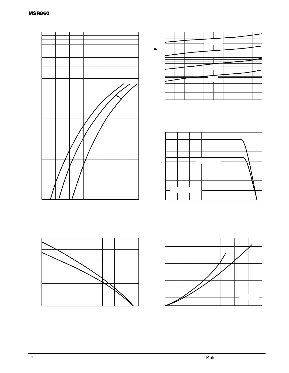
TYPICAL ELECTRICAL CHARACTERISTICS
100
10
, INSTANTANEOUS FORWARD CURRENT (AMPS)
F
I
TJ = 150°C
25°C
100°C
100
TJ = 150°C
m
10
1.0
, REVERSE CURRENT ( A)
R
I
0.1
VR, REVERSE VOLTAGE (VOLTS)
125°C
100°C
25°C
500
600400300200100
Figure 2. T ypical Reverse Current
14
12
10
8.0
dc
SQUARE WAVE
1.0
3.0
2.5
2.0
1.5
1.0
0.5
, AVERAGE FORW ARD CURRENT (AMPS)
F(AV)
0
I
6.0
4.0
RATED VR APPLIED
2.0
, AVERAGE FORW ARD CURRENT (AMPS)
F(AV)
0
1.91.30.90.5
1.71.10.7 1.5
VF, INSTANTANEOUS FORWARD VOLTAGE (VOLTS) TC, CASE TEMPERATURE (°C)
Figure 1. T ypical Forward Voltage
dc
SQUARE WAVE
RATED VR APPLIED
80
TA, AMBIENT TEMPERATURE (°C)
160120400
I
, AVERAGE POWER DISSIPATION (WATTS)
F(AV)
P
16
14
12
10
8.0
6.0
4.0
2.0
80
Figure 3. Current Derating, Case
SQUARE WAVE
0
I
, AVERAGE FORW ARD CURRENT (AMPS)
F(AV)
6.02.0 1210
dc
160120400
TJ = 150°C
148.04.00
Figure 4. Current Derating, Ambient
2
Figure 5. Power Dissipation
Motorola Rectifier Device Data
 Loading...