


System Release 2.21
MOTOTRBO
™
PCR
MOTOTRBO Customer
Programming Software
(CPS) 2.0 Online Help
DECEMBER 2020
©
2020 Motorola Solutions, Inc. All rights reserved
*MN006055A01*
MN006055A01-AD

MN006055A01-AD
Copyrights
Copyrights
The Motorola Solutions products described in this document may include copyrighted Motorola
Solutions computer programs. Laws in the United States and other countries preserve for Motorola
Solutions certain exclusive rights for copyrighted computer programs. Accordingly, any copyrighted
Motorola Solutions computer programs contained in the Motorola Solutions products described in this
document may not be copied or reproduced in any manner without the express written permission of
Motorola Solutions.
©
2020 Motorola Solutions, Inc. All Rights Reserved
No part of this document may be reproduced, transmitted, stored in a retrieval system, or translated
into any language or computer language, in any form or by any means, without the prior written
permission of Motorola Solutions, Inc.
Furthermore, the purchase of Motorola Solutions products shall not be deemed to grant either directly
or by implication, estoppel or otherwise, any license under the copyrights, patents or patent
applications of Motorola Solutions, except for the normal non-exclusive, royalty-free license to use that
arises by operation of law in the sale of a product.
Disclaimer
Please note that certain features, facilities, and capabilities described in this document may not be
applicable to or licensed for use on a specific system, or may be dependent upon the characteristics of
a specific mobile subscriber unit or configuration of certain parameters. Please refer to your Motorola
Solutions contact for further information.
Trademarks
MOTOROLA, MOTO, MOTOROLA SOLUTIONS, and the Stylized M Logo are trademarks or
registered trademarks of Motorola Trademark Holdings, LLC and are used under license. All other
trademarks are the property of their respective owners.
Open Source Content
This product contains Open Source software used under license. Refer to the product installation
media for full Open Source Legal Notices and Attribution content.
European Union (EU) Waste of Electrical and Electronic Equipment (WEEE)
directive
The European Union's WEEE directive requires that products sold into EU countries must have
the crossed out trash bin label on the product (or the package in some cases).
As defined by the WEEE directive, this cross-out trash bin label means that customers and end-users
in EU countries should not dispose of electronic and electrical equipment or accessories in household
waste.
Customers or end-users in EU countries should contact their local equipment supplier representative or
service centre for information about the waste collection system in their country.
2

MN006055A01-AD
Contact Us
Contact Us
The Solutions Support Center (SSC) is the primary contact for technical support included in your
organization's service agreement with Motorola Solutions.
Service agreement customers should be sure to call the SSC in all situations listed under Customer
Responsibilities in their agreement, such as:
• Before reloading software
• To confirm troubleshooting results and analysis before taking action
Your organization received support phone numbers and other contact information appropriate for your
geographic region and service agreement. Use that contact information for the most efficient response.
However, if needed, you can also find general support contact information on the Motorola Solutions
website, by following these steps:
1 Enter motorolasolutions.com in your browser.
2 Ensure that your organization's country or region is displayed on the page. Clicking or tapping the
name of the region provides a way to change it.
3 Select "Support" on the motorolasolutions.com page.
Comments
Send questions and comments regarding user documentation to
documentation@motorolasolutions.com.
Provide the following information when reporting a documentation error:
• The document title and part number
• The page number or title of the section with the error
• A description of the error
Motorola Solutions offers various courses designed to assist in learning about the system. For
information, go to https://learning.motorolasolutions.com to view the current course offerings and
technology paths.
3

MN006055A01-AD
Document History
Document History
Version Description Date
MN006055A01-AA Original release of the MOTOTR-
BOTM Customer Programming Software (CPS) 2.0 Online Help for PCR
2.10.5
MN006055A01-AB Added a new field under Network
Settings. See Device Discovery Serv-
er Name on page 435.
MN006055A01-AC Original release of the MOTOTRBO
Customer Programming Software
(CPS) 2.0 Online Help for PCR
2.11.0
MN006055A01-AD
Original release of the MOTOTRBO
Customer Programming Software
(CPS) 2.0 Online Help for 2.21
July 2019
July 2019
April 2020
December 2020
4

MN006055A01-AD
Contents
Contents
Copyrights................................................................................................................... 2
Contact Us................................................................................................................... 3
Document History....................................................................................................... 4
List of Figures............................................................................................................48
List of Tables............................................................................................................. 49
List of Procedures.....................................................................................................50
Helpful Background Information............................................................................. 51
Chapter 1: Introduction to Customer Programming Software (CPS) 2.0...........52
1.1 CPS 2.0 Overview................................................................................................................. 52
1.1.1 CPS 2.0 Menu and Actions Bars............................................................................. 54
1.1.1.1 CPS 2.0 File Selections............................................................................. 56
1.1.1.2 CPS 2.0 Device Selections........................................................................ 58
1.1.1.3 CPS 2.0 Licenses Selections..................................................................... 65
1.1.1.4 CPS 2.0 Tools Selections.......................................................................... 69
1.1.1.5 CPS 2.0 Help Selections............................................................................73
1.1.2 Set Categories......................................................................................................... 73
1.1.3 Programming Pane in CPS 2.0................................................................................74
1.1.4 Information Windows in CPS 2.0............................................................................. 76
1.1.4.1 Validation Results Window.........................................................................76
1.1.4.2 Warning Messages Window.......................................................................77
1.1.4.3 Search Results Window............................................................................. 77
1.1.4.4 Help Window.............................................................................................. 78
1.2 CPS 2.0 Concepts................................................................................................................. 78
1.2.1 Sets and Configurations in CPS 2.0........................................................................ 78
1.2.1.1 What are Sets and Configuration?............................................................. 78
1.2.1.2 Copy and Paste Operation.........................................................................79
1.2.2 Radio Identity Parameters....................................................................................... 79
1.2.3 Codeplug Version Support.......................................................................................80
1.2.4 CPS 2.0 Archive File Support.................................................................................. 81
1.2.5 Licensing Radio and Application Features...............................................................81
1.2.6 Application Log........................................................................................................ 82
1.3 Common Tasks in Customer Programming Software (CPS) 2.0...........................................82
1.3.1 Using Clone to Deploy a New Fleet of Radios.........................................................82
1.3.2 Using Clone Express to Modify Shared Parameters in a Deployed Fleet................83
1.3.3 Retrieving Firmware and Codeplug Update Package..............................................83
5

MN006055A01-AD
Contents
1.4 Differences between CPS 2.0 and CPS 1.0.......................................................................... 84
1.4.1 Features Not Supported in CPS 2.0........................................................................ 84
1.4.2 Multiple Document Support......................................................................................85
1.4.3 Configuring Voice Announcements and Language Packs.......................................85
1.4.3.1 Loading a Language Pack......................................................................... 85
1.4.3.2 Deleting a Language Pack......................................................................... 86
1.4.3.3 Loading Voice Announcement Files...........................................................86
1.4.3.4 Deleting a Voice Announcement................................................................87
1.4.3.5 Removing Imported Voice Announcements...............................................87
1.5 Troubleshooting in Customer Programming Software (CPS) 2.0.......................................... 87
1.5.1 Unable to Read or Write Codeplug to the Radio......................................................88
1.5.2 Unable to Recover a Radio......................................................................................88
1.5.3 Installing MOTOTRBO Driver Windows 7 and Later ...............................................89
1.5.4 Installing FlashZap Driver on Windows Windows 7 and Later.................................89
1.5.5 Communication Issues Due to Ethernet Properties................................................. 89
Chapter 2: Customer Programming Software (CPS) 2.0 Sets.............................91
2.1 Device Information.................................................................................................................91
2.1.1 Model Number......................................................................................................... 91
2.1.2 Tanapa Number....................................................................................................... 91
2.1.3 Region......................................................................................................................91
2.1.4 Serial Number.......................................................................................................... 91
2.1.5 Physical Serial Number............................................................................................92
2.1.6 Firmware ID............................................................................................................. 92
2.1.7 Frequency Range (MHz)..........................................................................................92
2.1.8 Power Range (W).................................................................................................... 92
2.1.9 Power Range (W).................................................................................................... 92
2.1.10 12V Power Range (W)........................................................................................... 92
2.1.11 24V Power Range (W)........................................................................................... 92
2.1.12 Firmware Type....................................................................................................... 92
2.1.13 Firmware Type....................................................................................................... 93
2.1.14 Firmware Version...................................................................................................93
2.1.15 Codeplug Version.................................................................................................. 93
2.1.16 Bootloader Version................................................................................................ 93
2.1.17 Netmask.................................................................................................................93
2.1.18 Last Programmed Date and Time..........................................................................93
2.1.19 MAC Address.........................................................................................................93
2.1.20 Wi-Fi MAC Address............................................................................................... 94
2.1.21 Controller FPGA Version....................................................................................... 94
2.1.22 Wireline FPGA Version.......................................................................................... 94
6

MN006055A01-AD
Contents
2.1.23 RX Frequency Range (MHz)..................................................................................94
2.1.24 RX Frequency Range (MHz)..................................................................................94
2.1.25 RX Frequency Range (MHz) (SL Series 800/900 MHz Radios)............................ 94
2.1.26 TX Frequency Range (MHz).................................................................................. 95
2.1.27 TX Frequency Range (MHz).................................................................................. 95
2.1.28 TX Frequency Range (MHz) (SL Series 800/900 MHz radios)..............................95
2.2 Welcome Bitmap Set............................................................................................................. 95
2.2.1 General (Welcome Bitmap)......................................................................................95
2.2.1.1 Welcome Image......................................................................................... 95
2.3 Language Packs Set..............................................................................................................96
2.3.1 Language................................................................................................................. 96
2.3.2 Locale...................................................................................................................... 96
2.4 General Settings Set..............................................................................................................96
2.4.1 General (General Settings)...................................................................................... 96
2.4.1.1 Subscriber Inactivity Timer (SIT) (ms)........................................................97
2.4.1.2 Radio Alias................................................................................................. 97
2.4.1.3 Radio ID..................................................................................................... 98
2.4.1.4 GNSS......................................................................................................... 98
2.4.1.5 GNSS......................................................................................................... 98
2.4.1.6 Private Calls............................................................................................... 99
2.4.1.7 Site Search Timer (sec)............................................................................. 99
2.4.1.8 ARS Initialization Delay (min).....................................................................99
2.4.1.9 TX Preamble Duration (ms)..................................................................... 100
2.4.1.10 Voice Pretime Duration.......................................................................... 100
2.4.1.11 TX Inhibit Quick Key Override................................................................101
2.4.1.12 Monitor Type.......................................................................................... 101
2.4.1.13 Min Speaker Volume Level (dB)............................................................ 102
2.4.1.14 Min Speaker Volume Muted...................................................................102
2.4.1.15 Unlink Monitor........................................................................................ 102
2.4.1.16 Off-Hook Disables PL.............................................................................102
2.4.1.17 Group Call Hang Time (ms)................................................................... 103
2.4.1.18 Private Call Hang Time (ms).................................................................. 103
2.4.1.19 Emergency Call Hang Time (ms)........................................................... 103
2.4.1.20 Talkaround Group Call Hang Time (ms)................................................ 104
2.4.1.21 Talkaround Private Call Hang Time (ms)............................................... 104
2.4.1.22 Call Hang Time (sec)............................................................................. 104
2.4.1.23 Repeat Gain (dB)................................................................................... 105
2.4.1.24 Antenna Relay Delay Timer (ms)........................................................... 105
2.4.1.25 Digital/Band 1 TX Low Power (W)..........................................................106
7

MN006055A01-AD
Contents
2.4.1.26 Digital/Band 1 TX High Power (W).........................................................106
2.4.1.27 Analog/Band 2 TX Low Power (W)........................................................ 106
2.4.1.28 Analog/Band 2 TX High Power (W)........................................................106
2.4.1.29 Digital TX Low Power (W) (SL Series Mid-Tier).....................................107
2.4.1.30 Digital TX High Power (W) (SL Series Mid-Tier) Note........................... 107
2.4.1.31 Digital TX High Power (W) (SL Series Mid-Tier).................................... 107
2.4.1.32 Analog TX Low Power (W) (SL Series Mid-Tier) ...................................107
2.4.1.33 Analog TX High Power (W) (SL Series Mid-Tier) ..................................107
2.4.1.34 Band 1 DC TX Power (W)...................................................................... 108
2.4.1.35 Band 2 DC TX Power (W)...................................................................... 108
2.4.1.36 12V DC TX Power (W)........................................................................... 108
2.4.1.37 24V DC TX Power (W)........................................................................... 108
2.4.1.38 Disable All LEDs.................................................................................... 108
2.4.1.39 Backup Repeater Connected................................................................. 109
2.4.1.40 Sign In/Sign Out..................................................................................... 109
2.4.1.41 Secure Sign In ID................................................................................... 109
2.4.1.42 TX Caller Alias....................................................................................... 109
2.4.1.43 Caller Alias............................................................................................. 109
2.4.1.44 Edit Caller Alias......................................................................................109
2.4.1.45 Test Mode.............................................................................................. 110
2.4.1.46 Scrambling Frequency........................................................................... 110
2.4.1.47 Battery Type...........................................................................................110
2.4.1.48 Home Channel Zone.............................................................................. 111
2.4.1.49 Home Channel....................................................................................... 111
2.4.1.50 Home Channel Reminder Interval (min) ................................................111
2.4.1.51 Antenna Selection.................................................................................. 111
2.4.1.52 Illegal Carrier Timer ...............................................................................112
2.4.1.53 Illegal Carrier RSSI Threshold .............................................................. 112
2.4.1.54 Illegal Carrier Feature Enable................................................................ 112
2.4.1.55 Radio Keep Alive....................................................................................112
2.4.1.56 Codeplug Password............................................................................... 112
2.4.1.57 Check for Password............................................................................... 114
2.4.1.58 Maximum Check for Password Attempts............................................... 114
8
2.4.1.59 Radio Certification Type.........................................................................114
2.4.1.60 Respond Caller...................................................................................... 114
2.4.1.61 Radio Language Display........................................................................ 115
2.4.1.62 Digital or Analog BSI.............................................................................. 115
2.4.1.63 Mute Timer (hour).................................................................................. 115
2.4.1.64 Face Down Mute Enable........................................................................115

MN006055A01-AD
Contents
2.4.1.65 Radio On Indicator................................................................................. 115
2.4.1.66 Remote Radio Control............................................................................115
2.4.1.67 Virtual Channel Stop.............................................................................. 116
2.4.2 Battery (General Settings)..................................................................................... 116
2.4.2.1 Battery......................................................................................................116
2.4.2.2 DC System Nominal.................................................................................116
2.4.2.3 DC Operation Only...................................................................................116
2.4.2.4 DC Primary Source.................................................................................. 116
2.4.2.5 Battery Charging...................................................................................... 116
2.4.2.6 Output Charger Voltage (V)..................................................................... 117
2.4.2.7 Output Charger Voltage 12V (V).............................................................. 117
2.4.2.8 Output Charger Voltage 24V (V).............................................................. 117
2.4.3 Alarm Type (General Settings).............................................................................. 117
2.4.3.1 Reference Clock Source Type................................................................. 117
2.4.3.2 External Clock Frequency........................................................................ 118
2.4.3.3 RF Power Control Alarm.......................................................................... 118
2.4.3.4 Power Unleveled Alarm............................................................................118
2.4.3.5 Modem PA Alarm..................................................................................... 118
2.4.3.6 Temperature Alarm.................................................................................. 118
2.4.3.7 Power Roll-back Alarm (2dB)...................................................................119
2.4.3.8 Power Roll-back Alarm (3dB)...................................................................119
2.4.3.9 VSWR Minor Alarm.................................................................................. 119
2.4.3.10 VSWR Major Alarm................................................................................ 120
2.4.3.11 PA Temp Alarm......................................................................................120
2.4.3.12 PA Fan Alarm.........................................................................................120
2.4.3.13 Power Supply Fan Alarm....................................................................... 120
2.4.3.14 Power Supply Over Temperature Alarm................................................ 121
2.4.3.15 AC Power Alarm.....................................................................................121
2.4.3.16 Bad Battery Alarm.................................................................................. 121
2.4.3.17 Low Battery Alarm..................................................................................121
2.4.3.18 Battery Disconnected Alarm...................................................................122
2.4.3.19 Modem Fan Alarm..................................................................................122
2.4.3.20 Illegal Carrier Alarm .............................................................................. 122
2.4.4 CWID (General Settings)....................................................................................... 122
2.4.4.1 ID..............................................................................................................122
2.4.4.2 Tone Frequency (Hz)............................................................................... 123
2.4.4.3 TX Interval (min).......................................................................................123
2.4.4.4 Configuration Bits.....................................................................................124
2.4.4.5 Mix Mode Timer (min).............................................................................. 124
9

MN006055A01-AD
Contents
2.4.5 Voting (General Settings).......................................................................................125
2.4.6 Audio Profile (General Settings)............................................................................ 127
2.4.7 Microphone (General Settings).............................................................................. 131
2.4.8 Back Light (General Settings)................................................................................ 134
2.4.9 Battery Saver (General Settings)........................................................................... 135
2.4.4.6 Rate (WPM)............................................................................................. 125
2.4.4.7 Strip PL.................................................................................................... 125
2.4.5.1 Operation Mode....................................................................................... 125
2.4.5.2 Digital Voter Peer ID................................................................................ 126
2.4.5.3 Digital Voting Stability Factor................................................................... 126
2.4.6.1 User Selectable Audio Profiles.................................................................127
2.4.6.2 Intelligent Audio Response...................................................................... 127
2.4.6.3 Language................................................................................................. 128
2.4.6.4 Environment............................................................................................. 128
2.4.6.5 Preference................................................................................................128
2.4.6.6 AF Suppressor......................................................................................... 129
2.4.6.7 Noise Suppressor.....................................................................................129
2.4.6.8 Fast Noise Suppressor Training Period (sec).......................................... 129
2.4.6.9 Trill Enhancement.................................................................................... 130
2.4.6.10 Analog RX Audio Leveling..................................................................... 130
2.4.6.11 Digital RX Audio Leveling.......................................................................130
2.4.7.1 Mic Selection Rule................................................................................... 131
2.4.7.2 Mic Distortion Control...............................................................................131
2.4.7.3 Analog Mic AGC.......................................................................................131
2.4.7.4 Mic AGC...................................................................................................131
2.4.7.5 Analog Mic Gain (dB)............................................................................... 132
2.4.7.6 Digital Mic Gain (dB)................................................................................ 133
2.4.7.7 VOX Sensitivity........................................................................................ 133
2.4.7.8 Hot Mic Source.........................................................................................134
2.4.8.1 On Receiving Over-the-Air Event.............................................................134
2.4.8.2 On User Event..........................................................................................134
2.4.8.3 Timeout Timer (Sec)................................................................................ 135
2.4.9.1 Preamble..................................................................................................135
10
2.4.9.2 Receive.................................................................................................... 135
2.4.9.3 Backlight (Battery Saver)......................................................................... 135
2.4.10 Alerts (General Settings)......................................................................................136
2.4.10.1 Disable All Tones................................................................................... 136
2.4.10.2 Escalert Tone......................................................................................... 136
2.4.10.3 Channel Free Indication Tone................................................................136

MN006055A01-AD
Contents
2.4.10.4 Self Test Pass Tone...............................................................................137
2.4.10.5 Prohibit Tone On Interrupt......................................................................137
2.4.10.6 Talk Permit Tone....................................................................................137
2.4.10.7 Volume Offset (dB).................................................................................137
2.4.10.8 Fixed Volume......................................................................................... 137
2.4.10.9 RX Low Battery Interval (sec)................................................................ 138
2.4.10.10 Emergency Search Tone..................................................................... 138
2.4.10.11 Emergency Search Tone Volume........................................................ 138
2.4.10.12 Emergency Search Tone Speaker....................................................... 139
2.4.10.13 Emergency Alert Tone Duration (min)..................................................139
2.4.10.14 Call Alert Tone Duration (sec)..............................................................139
2.4.10.15 Text Message Alert Tone Duration (min)............................................. 140
2.4.10.16 ARTS Tone.......................................................................................... 140
2.4.10.17 Visual Indication................................................................................... 140
2.4.10.18 Clear Call Received............................................................................. 140
2.4.10.19 Channel Knob Tone............................................................................. 141
2.4.11 Persistent LRRP Requests (General Settings).................................................... 141
2.4.11.1 Save....................................................................................................... 141
2.4.11.2 Delete.....................................................................................................141
2.4.12 Lone Worker (General Settings).......................................................................... 141
2.4.12.1 Response Timer (min)............................................................................141
2.4.12.2 Reminder Timer (sec)............................................................................ 142
2.4.12.3 Smart PTT Periodic Time (sec)..............................................................142
2.4.12.4 Carrier Gone Timer (sec)....................................................................... 142
2.4.13 Power Up (General Settings)............................................................................... 142
2.4.13.1 MDC Status............................................................................................142
2.4.13.2 Desired Channel Zone........................................................................... 143
2.4.13.3 Desired Channel.................................................................................... 143
2.4.14 Password and Lock (General Settings)............................................................... 143
2.4.14.1 Enable (Password and Lock)................................................................. 143
2.4.14.2 Password............................................................................................... 143
2.4.15 Front Programming Password (General Settings)............................................... 144
2.4.15.1 Mode...................................................................................................... 144
2.4.15.2 Password............................................................................................... 146
2.4.16 Delete All (General Settings)............................................................................... 146
2.4.16.1 Text Messages.......................................................................................146
2.4.16.2 Job Tickets............................................................................................. 146
2.4.16.3 Call Log.................................................................................................. 146
2.4.16.4 User Contacts........................................................................................ 146
11

MN006055A01-AD
Contents
2.4.17 Rental Timer (General Settings).......................................................................... 146
2.4.17.1 Rental Period (Hours)............................................................................ 147
2.4.17.2 Rental Extension Time (Hours).............................................................. 147
2.4.17.3 Rental Expiry Reminder (Hours)............................................................ 147
2.4.17.4 Rental Extension Status.........................................................................147
2.4.18 5 Tone Radio ID (General Settings).....................................................................147
2.4.18.1 U1...........................................................................................................148
2.4.18.2 U2...........................................................................................................148
2.4.18.3 U3...........................................................................................................148
2.4.18.4 U4...........................................................................................................148
2.4.18.5 U5...........................................................................................................148
2.4.18.6 U6...........................................................................................................148
2.4.18.7 U7...........................................................................................................149
2.4.18.8 U8...........................................................................................................149
2.5 Accessories Set................................................................................................................... 149
2.5.1 General (Accessories)........................................................................................... 149
2.5.1.1 Hook Type................................................................................................149
2.5.1.2 Volume Control........................................................................................ 149
2.5.1.3 Ignition Sense.......................................................................................... 150
2.5.1.4 Ignition Sense Auto Power Down Timer (min)......................................... 150
2.5.1.5 Handset....................................................................................................150
2.5.1.6 Analog Accessory Mic Gain (dB)............................................................. 151
2.5.1.7 Digital Accessory Mic Gain (dB)...............................................................151
2.5.1.8 Max Extra Loud Accessories Volume Level Attenuation (db).................. 152
2.5.1.9 Rx Audio Type..........................................................................................153
2.5.1.10 Data Revert Channel Zone.................................................................... 154
2.5.1.11 Data Revert Channel..............................................................................154
2.5.1.12 Analog Accessory Emphasis..................................................................154
2.5.1.13 Audio Type............................................................................................. 155
2.5.1.14 Audio Priority..........................................................................................156
2.5.1.15 TX Audio Priority.................................................................................... 156
2.5.1.16 Wireline TX Audio Priority...................................................................... 156
2.5.1.17 FP TX Audio Priority...............................................................................157
12
2.5.1.18 Repeater Audio Priority.......................................................................... 157
2.5.1.19 Disable Repeat Path.............................................................................. 157
2.5.1.20 Debounce Duration (ms)........................................................................ 158
2.5.1.21 Cable Type.............................................................................................158
2.5.1.22 Rear Emergency Pin Prior to Power Up.................................................159
2.5.2 Bluetooth® (Accessories).......................................................................................159

MN006055A01-AD
Contents
2.5.2.1 Analog Mic Gain (dB) (Bluetooth)............................................................ 159
2.5.2.2 Digital Mic Gain (dB) (Bluetooth)..............................................................159
2.5.3 Digital Audio (Accessories).................................................................................... 160
2.5.3.1 Speaker Slot.............................................................................................160
2.5.3.2 Microphone Slot....................................................................................... 160
2.5.3.3 Microphone Call Type.............................................................................. 160
2.5.3.4 Microphone Call Target ID....................................................................... 161
2.5.3.5 Repeat Audio Priority............................................................................... 161
2.5.3.6 Emergency Repeat Audio Priority............................................................ 161
2.5.3.7 Local Priority Audio.................................................................................. 161
2.5.4 GPIO Physical Pins (Accessories).........................................................................162
2.5.4.1 GPIO1 Feature.........................................................................................162
2.5.4.2 GPIO1 Active Level..................................................................................162
2.5.4.3 GPIO1 Debounce.....................................................................................162
2.5.4.4 GPIO1 GNSS Report............................................................................... 163
2.5.4.5 GPIO2 Feature.........................................................................................163
2.5.4.6 GPIO2 Active Level..................................................................................163
2.5.4.7 GPIO2 Debounce.....................................................................................163
2.5.4.8 GPIO2 GNSS Report............................................................................... 163
2.5.4.9 GPIO3 Feature.........................................................................................164
2.5.4.10 GPIO3 Active Level................................................................................164
2.5.4.11 GPIO3 Debounce...................................................................................164
2.5.4.12 GPIO3 GNSS Report............................................................................. 164
2.5.4.13 GPIO4 Feature.......................................................................................165
2.5.4.14 GPIO4 Active Level................................................................................165
2.5.4.15 GPIO4 Debounce...................................................................................165
2.5.4.16 GPIO4 GNSS Report............................................................................. 165
2.5.4.17 GPIO5 Feature.......................................................................................166
2.5.4.18 GPIO5 Active Level................................................................................166
2.5.4.19 GPIO5 Debounce...................................................................................166
2.5.4.20 GPIO5 GNSS Report............................................................................. 166
2.5.4.21 GPIO6 Feature.......................................................................................166
2.5.4.22 GPIO6 Active Level................................................................................167
2.5.4.23 GPIO6 Debounce...................................................................................167
2.5.4.24 GPIO6 GNSS Report............................................................................. 167
2.5.4.25 GPIO7 Feature.......................................................................................167
2.5.4.26 GPIO7 Active Level................................................................................168
2.5.4.27 GPIO7 Debounce...................................................................................168
2.5.4.28 GPIO7 GNSS Report............................................................................. 168
13

MN006055A01-AD
Contents
2.5.5 Horns and Lights (Accessories)............................................................................. 179
2.5.6 Wireline (Accessories)........................................................................................... 180
2.5.4.29 GPIO8 Feature.......................................................................................168
2.5.4.30 GPIO8 Active Level................................................................................169
2.5.4.31 GPIO8 Debounce...................................................................................169
2.5.4.32 GPIO8 GNSS Report............................................................................. 169
2.5.4.33 GPIO9 Feature.......................................................................................169
2.5.4.34 GPIO9 Active Level................................................................................169
2.5.4.35 GPIO9 Debounce...................................................................................169
2.5.4.36 GPIO10 Feature.....................................................................................170
2.5.4.37 GPIO10 Active Level..............................................................................170
2.5.4.38 GPIO10 Debounce.................................................................................170
2.5.4.39 GPIO10 GNSS Report........................................................................... 170
2.5.4.40 GPIO11 Feature.....................................................................................170
2.5.4.41 GPIO11 Active Level..............................................................................171
2.5.4.42 GPIO11 Debounce.................................................................................171
2.5.4.43 GPIO12 Feature.....................................................................................171
2.5.4.44 GPIO 12 Active Level.............................................................................171
2.5.4.45 GPIO12 Debounce.................................................................................171
2.5.4.46 GPIO Function Selections......................................................................172
2.5.4.47 GNSS Report......................................................................................... 179
2.5.5.1 Alarm........................................................................................................179
2.5.5.2 Duration (sec)...........................................................................................180
2.5.5.3 Delay Time (sec)...................................................................................... 180
2.5.6.1 Remote Control Mode.............................................................................. 180
2.5.6.2 Wire Mode................................................................................................181
2.5.6.3 Line Impedance........................................................................................181
2.5.6.4 TX Guard Tone........................................................................................ 182
2.5.6.5 PTT Dropout Timer (ms).......................................................................... 182
2.5.6.6 Revert Channel Zone............................................................................... 182
2.5.6.7 Revert Channel........................................................................................ 182
2.5.6.8 Monitor Mode........................................................................................... 183
2.5.6.9 Squelch Hysteresis (dB)...........................................................................183
14
2.5.6.10 HLGT ALC Mode....................................................................................183
2.5.6.11 Status Tone............................................................................................183
2.5.6.12 RX Guard Tone...................................................................................... 184
2.5.6.13 Repeater Fallback Timer (ms)................................................................184
2.5.6.14 RX Squelch Mode.................................................................................. 184
2.5.6.15 Scan Mode............................................................................................. 185

MN006055A01-AD
Contents
2.5.7 Wireline 2 (Accessories)........................................................................................ 185
2.5.7.1 Remote Control Mode.............................................................................. 185
2.5.7.2 Wire Mode................................................................................................186
2.5.7.3 Line Impedance........................................................................................186
2.5.7.4 TX Guard Tone........................................................................................ 187
2.5.7.5 PTT Dropout Timer (ms).......................................................................... 187
2.5.7.6 Monitor Mode........................................................................................... 187
2.5.7.7 Squelch Hysteresis (dB)...........................................................................188
2.5.7.8 HLGT ALC Mode......................................................................................188
2.5.7.9 Status Tone..............................................................................................188
2.5.7.10 RX Guard Tone...................................................................................... 188
2.5.7.11 Repeater Fallback Timer (ms)................................................................188
2.5.7.12 RX Squelch Mode.................................................................................. 189
2.5.7.13 TX Guard Tone Notch............................................................................ 189
2.5.7.14 RX Status Tone Notch........................................................................... 189
2.5.8 Multi-Button PTT (Accessories)............................................................................. 189
2.5.8.1 Index 1 Zone (Multi-Button PTT)..............................................................190
2.5.8.2 Index 1 (Multi-Button PTT)....................................................................... 190
2.5.8.3 Index 2 Zone (Multi-Button PTT)..............................................................190
2.5.8.4 Index 2 (Multi-Button PTT)....................................................................... 190
2.5.8.5 Index 3 Zone (Multi-Button PTT)..............................................................190
2.5.8.6 Index 3 (Multi-Button PTT)....................................................................... 190
2.5.8.7 Index 4 Zone (Multi-Button PTT)..............................................................191
2.5.8.8 Index 4 (Multi-Button PTT)....................................................................... 191
2.5.8.9 Index 5 Zone (Multi-Button PTT)..............................................................191
2.5.8.10 Index 5 (Multi-Button PTT)..................................................................... 191
2.5.8.11 Index 6 Zone (Multi-Button PTT)............................................................191
2.5.8.12 Index 6 (Multi-Button PTT)..................................................................... 192
2.5.8.13 Index 7 (Multi-Button PTT)..................................................................... 192
2.5.8.14 Index 7 Zone (Multi-Button PTT)............................................................192
2.5.9 Wireline TRC (Accessories)...................................................................................192
2.5.9.1 TX Guard Tone Notch.............................................................................. 192
2.5.9.2 RX Status Tone Notch............................................................................. 192
2.5.9.3 Antenna Relay..........................................................................................192
2.5.10 Wireline TRC Function Selection (Accessories).................................................. 193
2.5.10.1 TRC7 Frequency 1.................................................................................193
2.5.10.2 TRC7 Frequency 2.................................................................................193
2.5.10.3 TRC7 Frequency 3.................................................................................194
2.5.10.4 TRC7 Frequency 4.................................................................................194
15

MN006055A01-AD
Contents
2.5.10.5 TRC7 Frequency 5.................................................................................195
2.5.10.6 TRC7 Frequency 6.................................................................................195
2.5.10.7 TRC7 Frequency 7.................................................................................196
2.5.10.8 TRC7 Frequency 8.................................................................................196
2.5.10.9 TRC7 Frequency 9.................................................................................197
2.5.10.10 TRC7 Frequency 10.............................................................................197
2.5.10.11 TRC7 Frequency 11.............................................................................198
2.5.10.12 TRC7 Frequency 12.............................................................................198
2.5.10.13 TRC7 Frequency 13.............................................................................199
2.5.10.14 TRC7 Frequency 14.............................................................................199
2.5.10.15 TRC7 Frequency 15.............................................................................200
2.5.10.16 TRC7 Frequency 16.............................................................................200
2.5.10.17 TRC15 Frequency 1.............................................................................201
2.5.10.18 TRC15 Frequency 2.............................................................................201
2.5.10.19 TRC15 Frequency 3.............................................................................201
2.5.10.20 TRC15 Frequency 4.............................................................................201
2.5.10.21 TRC15 Frequency 5.............................................................................202
2.5.10.22 TRC15 Frequency 6.............................................................................202
2.5.10.23 TRC15 Frequency 7.............................................................................202
2.5.10.24 TRC15 Frequency 8.............................................................................202
2.5.10.25 TRC15 Frequency 9.............................................................................202
2.5.10.26 TRC15 Frequency 10...........................................................................203
2.5.10.27 TRC15 Frequency 11...........................................................................203
2.5.10.28 TRC15 Frequency 12...........................................................................203
2.5.10.29 TRC15 Frequency 13...........................................................................203
2.5.10.30 TRC15 Frequency 14...........................................................................204
2.5.10.31 TRC15 Frequency 15...........................................................................204
2.5.10.32 TRC15 Frequency 16...........................................................................204
2.6 Control Buttons Set..............................................................................................................204
2.6.1 General (Control Buttons)...................................................................................... 204
2.6.1.1 Numeric Keypad.......................................................................................205
2.6.1.2 Emergency Short Press Duration (ms).................................................... 205
2.6.1.3 Long Press Duration (ms)........................................................................ 205
16
2.6.1.4 Dual Knob Press Duration (ms)............................................................... 205
2.6.1.5 Channel Up/Down via Knob..................................................................... 206
2.6.1.6 Keypad Lock Options............................................................................... 206
2.6.2 Conventional Radio Buttons Portable (Control Buttons)........................................206
2.6.2.1 Orange Button Short Press (Portable)..................................................... 206
2.6.2.2 Orange Button Long Press (Portable)......................................................211

MN006055A01-AD
Contents
2.6.2.3 Side Button 1 Short Press (Portable)....................................................... 216
2.6.2.4 Side Button 1 Long Press (Portable)........................................................221
2.6.2.5 Side Button 2 Short Press (Portable)....................................................... 226
2.6.2.6 Side Button 2 Long Press (Portable)........................................................232
2.6.2.7 Side Button 3 Short Press (Portable)....................................................... 237
2.6.2.8 Side Button 3 Long Press (Portable)........................................................242
2.6.2.9 P1 Button Short Press (Portable).............................................................247
2.6.2.10 P1 Button Long Press (Portable)........................................................... 252
2.6.2.11 P2 Button Short Press (Portable)...........................................................257
2.6.2.12 P2 Button Long Press (Portable)........................................................... 262
2.6.3 Conventional Radio Buttons Mobile (Control Buttons)...........................................267
2.6.3.1 Front Button 1 Short Press (Mobile).........................................................267
2.6.3.2 Front Button 1 Long Press (Mobile)......................................................... 272
2.6.3.3 Front Button 2 Short Press (Mobile).........................................................277
2.6.3.4 Front Button 2 Long Press (Mobile)......................................................... 282
2.6.3.5 Front Button 3 Short Press (Mobile).........................................................286
2.6.3.6 Front Button 3 Long Press (Mobile)......................................................... 291
2.6.3.7 Front Button 4 Short Press (Mobile).........................................................296
2.6.3.8 Front Button 4 Long Press (Mobile) ........................................................ 301
2.6.4 Conventional Accessory Buttons Portable (Control Buttons).................................305
2.6.4.1 Orange Button Short Press (Portable) (Accessory Button)......................306
2.6.4.2 Orange Button Long Press (Portable) (Accessory Button)...................... 311
2.6.4.3 No Dot Button Short Press (Portable) (Accessory Button).......................316
2.6.4.4 No Dot / A Button Long Press (Portable) (Accessory Button)..................321
2.6.4.5 1-Dot Button Long Press (Portable) (Accessory Button)..........................326
2.6.4.6 1-Dot Button Short Press (Portable) (Accessory Button)......................... 331
2.6.4.7 2-Dot Button Short Press (Portable) (Accessory Button)......................... 336
2.6.4.8 2-Dot Button Long Press (Portable) (Accessory Button)..........................341
2.6.5 Conventional Accessory Buttons Mobile (Control Buttons)................................... 347
2.6.5.1 No Dot Button Short Press (Mobile) (Accessory Button)......................... 347
2.6.5.2 No Dot / A Button Long Press (Mobile) (Accessory Button).....................351
2.6.5.3 1-Dot / B Button Short Press (Mobile) (Accessory Button)...................... 356
2.6.5.4 1-Dot / B Button Long Press (Mobile) (Accessory Button)....................... 361
2.6.5.5 2-Dot / C Button Short Press (Mobile) (Accessory Button)...................... 366
2.6.5.6 2-Dot / C Button Long Press (Mobile) (Accessory Button).......................371
2.6.6 One Touch Access (Control Buttons).................................................................... 376
2.6.6.1 One Touch Access...................................................................................376
2.6.6.2 Mode (One Touch Access)...................................................................... 376
2.6.6.3 Channel Zone...........................................................................................376
17

MN006055A01-AD
Contents
2.6.6.4 Channel....................................................................................................377
2.6.6.5 Call (One Touch Access)......................................................................... 377
2.6.6.6 Call Type (One Touch Access)................................................................ 377
2.6.6.7 5 Tone Call (One Touch Access)............................................................. 378
2.6.6.8 MDC Status/Message Index (One Touch Access)...................................378
2.6.6.9 Text Message (One Touch Access).........................................................378
2.6.7 Number Key Quick Contact Access (Control Buttons)...........................................378
2.6.7.1 Number Key (Number Key Quick Contact Access)..................................378
2.6.7.2 Mode (Number Key Quick Contact Access).............................................379
2.6.7.3 Call (Number Key Quick Contact Access)............................................... 379
2.6.8 Actions List (Control Buttons)................................................................................ 379
2.6.8.1 Index (Actions List)...................................................................................380
2.6.8.2 Feature (Action List).................................................................................380
2.7 Text Messages Set.............................................................................................................. 383
2.7.1 General (Text Messages)...................................................................................... 384
2.7.1.1 Max Length of Message Sent.................................................................. 384
2.7.1.2 Message...................................................................................................384
2.8 Telemetry Set...................................................................................................................... 384
2.8.1 General (Telemetry)...............................................................................................384
2.8.1.1 Feature.....................................................................................................384
2.8.1.2 Description............................................................................................... 385
2.8.1.3 Action....................................................................................................... 385
2.8.1.4 Pulse Time............................................................................................... 386
2.8.1.5 Mode........................................................................................................ 386
2.8.1.6 Channel Zone...........................................................................................386
2.8.1.7 Channel....................................................................................................386
2.8.1.8 Call........................................................................................................... 387
2.8.1.9 Target VIO................................................................................................387
2.8.1.10 Text Message.........................................................................................388
2.9 Menu Set............................................................................................................................. 388
2.9.1 General (Menu)......................................................................................................388
2.9.1.1 Editor Hang Time (sec)............................................................................ 388
2.9.1.2 Menu Hang Time (sec).............................................................................388
18
2.9.1.3 Text Message (Menu).............................................................................. 388
2.9.1.4 Job Tickets Main Name............................................................................389
2.9.1.5 Job Tickets Short Name...........................................................................389
2.9.1.6 Job Ticket Delete..................................................................................... 389
2.9.1.7 Message (Menu)...................................................................................... 389
2.9.1.8 Wi-Fi.........................................................................................................389

MN006055A01-AD
Contents
2.9.2 Contact (Menu)...................................................................................................... 389
2.9.2.1 Call Alert (Menu)...................................................................................... 389
2.9.2.2 Edit (Menu)...............................................................................................390
2.9.2.3 Ring Style (Menu).................................................................................... 390
2.9.2.4 Text Message Alert (Menu)......................................................................390
2.9.2.5 Manual Dial (Menu)..................................................................................390
2.9.2.6 Phone Manual Dial (Menu)...................................................................... 391
2.9.2.7 Radio Check (Menu)................................................................................ 391
2.9.2.8 Remote Monitor (Menu)........................................................................... 391
2.9.2.9 Radio Enable (Menu)............................................................................... 391
2.9.2.10 Radio Disable (Menu)............................................................................ 391
2.9.2.11 Program Key (Menu)..............................................................................392
2.9.3 Scan (Menu).......................................................................................................... 392
2.9.3.1 Scan (Menu).............................................................................................392
2.9.3.2 Edit List (Menu)........................................................................................ 392
2.9.3.3 Select New List (Menu)............................................................................ 393
2.9.4 TMS (Menu)........................................................................................................... 393
2.9.5 Flexible RX List (Menu)..........................................................................................393
2.9.5.1 Flexible RX Group List (Menu).................................................................393
2.9.6 Status (Menu)........................................................................................................ 393
2.9.6.1 Manual Dial (Menu)..................................................................................393
2.9.6.2 Edit (Menu)...............................................................................................393
2.9.7 Call Log (Menu)..................................................................................................... 393
2.9.7.1 Answered (Menu).....................................................................................394
2.9.7.2 Missed (Menu)......................................................................................... 394
2.9.7.3 Outgoing Radio (Menu)............................................................................394
2.9.8 Utilities (Menu)....................................................................................................... 394
2.9.8.1 Talkaround (Menu)...................................................................................394
2.9.8.2 Tones/Alerts (Menu).................................................................................394
2.9.8.3 Horn/Lights (Menu).................................................................................. 395
2.9.8.4 Power (Menu)...........................................................................................395
2.9.8.5 Backlight (Menu)...................................................................................... 395
2.9.8.6 Backlight Timer (Menu)............................................................................ 395
2.9.8.7 Trill Enhancement (Menu)........................................................................395
2.9.8.8 Intro Screen (Menu)................................................................................. 395
2.9.8.9 Keypad Lock (Menu)................................................................................ 395
2.9.8.10 LED Indicator (Menu)............................................................................. 396
2.9.8.11 Squelch (Menu)......................................................................................396
2.9.8.12 Privacy (Menu)....................................................................................... 396
19

MN006055A01-AD
Contents
2.9.8.13 VOX (Menu)........................................................................................... 396
2.9.8.14 Cable Type (Menu)................................................................................ 396
2.9.8.15 Manual Site Roam (Menu)..................................................................... 396
2.9.8.16 Site Lock (Menu).................................................................................... 397
2.9.8.17 Password and Lock (Menu)................................................................... 397
2.9.8.18 Call Forward (Menu).............................................................................. 397
2.9.8.19 Mic Distortion Control (Menu)................................................................ 398
2.9.8.20 AF Suppressor (Menu)...........................................................................398
2.9.8.21 Mic Gain (Menu).....................................................................................398
2.9.8.22 Edit 5 Tone SUID (Menu).......................................................................398
2.9.8.23 Signaling System (Menu)....................................................................... 398
2.9.8.24 Edit Zone (Menu)................................................................................... 398
2.9.8.25 Edit Channel (Menu).............................................................................. 398
2.9.8.26 Radio Button (Menu).............................................................................. 398
2.9.8.27 Accessory Button (Menu).......................................................................399
2.9.8.28 Home Channel....................................................................................... 399
2.9.8.29 GNSS (Menu).........................................................................................399
2.9.8.30 Scrambling............................................................................................. 399
2.9.8.31 Indoor Location...................................................................................... 399
2.10 Security Set....................................................................................................................... 399
2.10.1 Fixed Privacy Key Decryption.............................................................................. 399
2.10.2 Ignore Rx Clear Voice/Packet Data..................................................................... 399
2.10.3 Privacy (Security).................................................................................................399
2.10.3.1 Privacy Type.......................................................................................... 400
2.10.3.2 Basic Privacy Key.................................................................................. 400
2.10.3.3 Adding Enhanced Privacy Keys............................................................. 401
2.10.3.4 Deleting Enhanced Privacy Keys........................................................... 401
2.10.3.5 Key ID.................................................................................................... 401
2.10.3.6 Key Alias................................................................................................ 402
2.10.3.7 Key Value...............................................................................................402
2.10.4 AES (Security)..................................................................................................... 402
2.10.4.1 Symmetric Keys..................................................................................... 402
2.10.4.2 Adding Symmetric Keys......................................................................... 403
20
2.10.4.3 Deleting Symmetric Keys....................................................................... 403
2.10.4.4 Key ID.................................................................................................... 403
2.10.4.5 Key Alias................................................................................................ 404
2.10.4.6 Key Value...............................................................................................404
2.10.5 Restricted Access to System (Security)...............................................................405
2.10.5.1 Authentication (RAS)..............................................................................405

MN006055A01-AD
Contents
2.10.5.2 Add (RAS Alias)..................................................................................... 405
2.10.5.3 Delete (Restricted Access to System)....................................................406
2.10.5.4 Authentication Key Alias........................................................................ 406
2.10.5.5 Key Alias................................................................................................ 406
2.10.5.6 Key Value...............................................................................................406
2.10.5.7 Authentication Key (RAS)...................................................................... 407
2.10.5.8 Radio ID Range Check.......................................................................... 407
2.10.5.9 Add (Radio ID Range)............................................................................408
2.10.5.10 Delete (Radio ID Range)......................................................................408
2.10.5.11 Min Radio ID........................................................................................ 408
2.10.5.12 Max Radio ID....................................................................................... 408
2.10.5.13 Allow.....................................................................................................409
2.10.6 Over-the-Air Programming (Security).................................................................. 409
2.10.6.1 Authentication Key ID.............................................................................409
2.10.6.2 Authentication Key Value....................................................................... 409
2.10.6.3 Authentication Key Alias........................................................................ 409
2.10.7 TLS-PSK Authentication (Security)......................................................................410
2.10.7.1 Security Mode........................................................................................ 410
2.10.7.2 Pre-Shared Key Value........................................................................... 410
2.10.7.3 Pre-Shared Key Alias.............................................................................410
2.11 Network Set....................................................................................................................... 410
2.11.1 General (Network)................................................................................................410
2.11.1.1 Radio IP................................................................................................. 411
2.11.1.2 Accessory IP.......................................................................................... 411
2.11.1.3 USB DNS-SD Interval............................................................................ 411
2.11.2 Radio Network (Network).....................................................................................412
2.11.2.1 CAI Group Network................................................................................ 412
2.11.2.2 CAI Network........................................................................................... 412
2.11.2.3 Max TX PDU Size (bytes)...................................................................... 413
2.11.2.4 Telemetry UDP Port............................................................................... 413
2.11.2.5 Forward to PC........................................................................................ 413
2.11.3 Services (Network)...............................................................................................414
2.11.3.1 ARS Radio ID.........................................................................................414
2.11.3.2 ARS IP................................................................................................... 414
2.11.3.3 ARS UDP Port........................................................................................415
2.11.3.4 TMS Radio ID.........................................................................................415
2.11.3.5 TMS IP................................................................................................... 415
2.11.3.6 TMS UDP Port....................................................................................... 415
2.11.3.7 User Defined UDP Port 1....................................................................... 416
21

MN006055A01-AD
Contents
2.11.4 Control Station (Network).....................................................................................418
2.11.5 Network Setting (Network)................................................................................... 422
2.11.6 IP Site Connect (Network)................................................................................... 424
2.11.7 IP Repeater Programming (Network)...................................................................425
2.11.3.8 User Defined UDP Port 2....................................................................... 416
2.11.3.9 User Defined UDP Port 3....................................................................... 417
2.11.3.10 XCMP Server ID...................................................................................417
2.11.3.11 XCMP Server IP...................................................................................417
2.11.3.12 Battery Management Server ID............................................................418
2.11.3.13 Battery Management Server IP............................................................418
2.11.4.1 Fixed Installation.................................................................................... 418
2.11.4.2 Voice Only..............................................................................................419
2.11.4.3 Data Modem System Type.....................................................................419
2.11.4.4 Data Modem Window Size.....................................................................419
2.11.4.5 Repeater Latitude (Degree)................................................................... 419
2.11.4.6 Repeater Longitude (Degree)................................................................ 420
2.11.4.7 ARS Monitoring ID................................................................................. 420
2.11.4.8 ARS Monitoring IP..................................................................................420
2.11.4.9 Location Server UDP Port......................................................................421
2.11.4.10 XCMP Server UDP Port....................................................................... 421
2.11.4.11 Battery Management Server UDP Port................................................ 421
2.11.5.1 DHCP..................................................................................................... 422
2.11.5.2 Ethernet IP............................................................................................. 422
2.11.5.3 Gateway IP.............................................................................................422
2.11.5.4 Gateway Netmask..................................................................................423
2.11.5.5 Link Speed............................................................................................. 423
2.11.5.6 DNCP..................................................................................................... 423
2.11.5.7 Ethernet IP............................................................................................. 423
2.11.5.8 Gateway IP.............................................................................................423
2.11.5.9 Gateway Netmask..................................................................................424
2.11.5.10 Primary DNS Server IP........................................................................ 424
2.11.5.11 Secondary DNS Server IP................................................................... 424
2.11.6.1 Beacon Interval (sec)............................................................................. 424
22
2.11.7.1 Enable (IP Repeater Programming).......................................................425
2.11.8 Bluetooth (Network)............................................................................................. 425
2.11.8.1 Enable (Bluetooth)................................................................................. 425
2.11.8.2 Country Code Channel...........................................................................425
2.11.8.3 Reconnect TOT (min).............................................................................425
2.11.8.4 Off-Hook.................................................................................................425

MN006055A01-AD
Contents
2.11.8.5 Rear PTT Audio Routing........................................................................ 426
2.11.8.6 Remote HSP Address............................................................................ 426
2.11.8.7 Remote SPP Address............................................................................ 426
2.11.8.8 POD PTT Device Address..................................................................... 426
2.11.8.9 HSP Fixed Pin........................................................................................426
2.11.8.10 SPP Fixed Pin...................................................................................... 427
2.11.8.11 Permanent Discoverable......................................................................427
2.11.8.12 Device Database Erase on Power Up..................................................427
2.11.8.13 DNS-SD Interval...................................................................................427
2.11.9 Bluetooth Serial Port Profile Data Routing (Network).......................................... 428
2.11.9.1 Destination (Bluetooth Serial Port).........................................................428
2.11.9.2 Destination Network Type (Bluetooth)................................................... 428
2.11.9.3 Destination Radio ID (Bluetooth)............................................................428
2.11.9.4 Destination IP (Bluetooth)...................................................................... 429
2.11.9.5 Destination UDP Port (Bluetooth).......................................................... 429
2.11.10 USB HID Data Routing (Network)......................................................................429
2.11.10.1 Destination (USB)................................................................................ 430
2.11.10.2 Destination Network Type (USB)......................................................... 430
2.11.10.3 USB Destination Radio ID (USB)......................................................... 430
2.11.10.4 Destination IP (USB)............................................................................ 430
2.11.10.5 Destination UDP Port (USB)................................................................ 430
2.11.11 Time Zone (Network)......................................................................................... 431
2.11.11.1 Daylight Saving Time........................................................................... 431
2.11.11.2 Directional Offset..................................................................................431
2.11.11.3 Hour Offset...........................................................................................431
2.11.11.4 Fractional Hours...................................................................................431
2.11.12 NTP Settings (Network)..................................................................................... 431
2.11.12.1 DHCP................................................................................................... 432
2.11.12.2 DNS......................................................................................................432
2.11.12.3 NTP Server IP...................................................................................... 432
2.11.12.4 NTP DNS Address............................................................................... 432
2.11.12.5 RTC Refresh Interval (hr).....................................................................432
2.11.13 DNS Address (Network).....................................................................................432
2.11.13.1 Hostname.............................................................................................432
2.11.14 General (WiFi Network)..................................................................................... 433
2.11.14.1 Enable.................................................................................................. 433
2.11.14.2 802.11D................................................................................................433
2.11.14.3 Regulatory Region............................................................................... 433
2.11.14.4 DHCP................................................................................................... 433
23

MN006055A01-AD
Contents
2.11.14.5 IP Address............................................................................................434
2.11.14.6 Gateway IP...........................................................................................434
2.11.14.7 Gateway Netmask................................................................................434
2.11.14.8 Primary DNS Server IP........................................................................ 434
2.11.14.9 Secondary DNS Server IP................................................................... 434
2.11.14.10 DNS-SD Interval.................................................................................434
2.11.14.11 Device Discovery Server Name......................................................... 435
2.11.14.12 Network SSID.....................................................................................435
2.11.14.13 Security Type..................................................................................... 435
2.11.14.14 Encrypted Network Password............................................................ 435
2.11.14.15 Roaming Aggressiveness.................................................................. 436
2.11.14.16 Boost Tx Power..................................................................................436
2.11.15 WAVE 5000 (Network).......................................................................................436
2.11.15.1 WAVE Server Type.............................................................................. 436
2.11.15.2 Server Name........................................................................................ 436
2.11.15.3 Share Location..................................................................................... 437
2.11.15.4 Jitter Voice Buffer (sec)........................................................................437
2.11.15.5 WAVE 5000 Username........................................................................ 437
2.11.15.6 WAVE 5000 Password.........................................................................437
2.11.15.7 WAVE OnCloud................................................................................... 437
2.11.16 WAVE OnCloud (Network).................................................................................437
2.11.16.1 WAVE OnCloud URL........................................................................... 437
2.11.16.2 Share Location..................................................................................... 438
2.11.16.3 VOX State............................................................................................ 438
2.12 MOTOTRBO Link Set........................................................................................................ 438
2.12.1 Link Mode............................................................................................................ 439
2.12.2 Site Type..............................................................................................................439
2.12.3 Repeater Type..................................................................................................... 440
2.12.4 GPIO Slot Timing Master..................................................................................... 440
2.12.5 Maximum Number of Links.................................................................................. 440
2.12.6 Link Beacon Interval (sec)................................................................................... 441
2.12.7 IP Site Connect MOTOTRBO Link Site............................................................... 441
2.13 Phone System Set............................................................................................................. 441
24
2.13.1 General (Phone System)..................................................................................... 441
2.13.1.1 Deaccess Code......................................................................................441
2.13.1.2 Busy TOT (sec)...................................................................................... 442
2.13.1.3 Response TOT (sec)..............................................................................442
2.13.1.4 TX Tone Duration (ms)...........................................................................442
2.13.1.5 TX Tone Interval (ms)............................................................................ 443

MN006055A01-AD
Contents
2.13.1.6 Ring Tone Level (dB)............................................................................. 443
2.13.1.7 Busy Tone Level (dB).............................................................................444
2.13.1.8 Enable All Call .......................................................................................444
2.13.1.9 Response Required............................................................................... 444
2.13.2 Target ID (Phone System)................................................................................... 444
2.13.2.1 Length.................................................................................................... 444
2.13.2.2 Entry Time (sec).....................................................................................445
2.13.2.3 Validation Attempts................................................................................ 445
2.13.2.4 Request Tone Level (dB)....................................................................... 445
2.13.3 Preconfigured Call (Phone System).....................................................................445
2.13.3.1 Enable (Preconfigured Call)................................................................... 445
2.13.3.2 Call Type (Preconfigured Call)............................................................... 446
2.13.3.3 Call ID (Preconfigured Call)................................................................... 446
2.14 Sites Set............................................................................................................................ 446
2.14.1 General (Sites).....................................................................................................446
2.14.1.1 Max Number of Sites..............................................................................447
2.14.1.2 Max Number of Trunked Repeaters per Site......................................... 447
2.14.1.3 Site ID (Neighboring Site)...................................................................... 447
2.14.1.4 Reserved Wide Area Channels..............................................................447
2.14.1.5 Neighbor 1..............................................................................................448
2.14.1.6 Neighbor 2..............................................................................................448
2.14.1.7 Neighbor 3..............................................................................................448
2.14.1.8 Neighbor 4..............................................................................................449
2.14.1.9 Neighbor 5..............................................................................................449
2.14.1.10 Neighbor 6............................................................................................449
2.15 Talkgroups Set...................................................................................................................449
2.15.1 General (Talkgroups)........................................................................................... 450
2.15.1.1 All Wide Area Talkgroups.......................................................................450
2.15.1.2 Call ID (Wide Area Talkgroups)............................................................. 450
2.15.1.3 Site 1...................................................................................................... 450
2.15.1.4 Site 2...................................................................................................... 451
2.15.1.5 Site 3...................................................................................................... 451
2.15.1.6 Site 4...................................................................................................... 451
2.15.1.7 Site 5...................................................................................................... 451
2.15.1.8 Site 6...................................................................................................... 452
2.15.1.9 Site 7...................................................................................................... 452
2.15.1.10 Site 8.................................................................................................... 452
2.15.1.11 Site 9.................................................................................................... 452
2.15.1.12 Site 10.................................................................................................. 453
25

MN006055A01-AD
Contents
2.15.1.13 Site 11.................................................................................................. 453
2.15.1.14 Site 12.................................................................................................. 453
2.15.1.15 Site 13.................................................................................................. 453
2.15.1.16 Site 14.................................................................................................. 454
2.15.1.17 Site 15.................................................................................................. 454
2.15.1.18 Site 16.................................................................................................. 454
2.15.1.19 Site 17.................................................................................................. 454
2.15.1.20 Site 18.................................................................................................. 455
2.15.1.21 Site 19.................................................................................................. 455
2.15.1.22 Site 20.................................................................................................. 455
2.16 Voice Announcement Set.................................................................................................. 455
2.16.1 General (Voice Announcement)...........................................................................456
2.16.1.1 Announcement Type.............................................................................. 456
2.16.1.2 Priority.................................................................................................... 456
2.16.2 File List (Voice Announcement)........................................................................... 456
2.16.2.1 Select and All......................................................................................... 456
2.16.2.2 Select and None.....................................................................................456
2.16.2.3 Selected................................................................................................. 457
2.16.2.4 File Name...............................................................................................457
2.16.3 Voice Announcement File Selection (Voice Announcement)...............................457
2.16.3.1 Set Voice Files....................................................................................... 457
2.16.3.2 Clear Voice Files.................................................................................... 457
2.16.3.3 Intelligent Audio On................................................................................457
2.16.3.4 Intelligent Audio Off................................................................................457
2.16.3.5 All Alert Tones On.................................................................................. 457
2.16.3.6 All Alert Tones Off.................................................................................. 458
2.16.3.7 Backlight Auto On.................................................................................. 458
2.16.3.8 Backlight Auto Off.................................................................................. 458
2.16.3.9 Battery Low............................................................................................ 458
2.16.3.10 Battery Medium.................................................................................... 458
2.16.3.11 Battery High......................................................................................... 458
2.16.3.12 Brightness............................................................................................ 459
2.16.3.13 Brightness level 1.................................................................................459
26
2.16.3.14 Brightness level 2.................................................................................459
2.16.3.15 Brightness level 3.................................................................................459
2.16.3.16 Brightness level 4.................................................................................459
2.16.3.17 Bluetooth Connect................................................................................459
2.16.3.18 Bluetooth Disconnect........................................................................... 460
2.16.3.19 Route Audio to Bluetooth..................................................................... 460

MN006055A01-AD
Contents
2.16.3.20 Route Audio to Speaker....................................................................... 460
2.16.3.21 Call Forwarding Set..............................................................................460
2.16.3.22 Call Forwarding Clear.......................................................................... 460
2.16.3.23 Call Alert...............................................................................................460
2.16.3.24 Call Log................................................................................................ 461
2.16.3.25 Contacts............................................................................................... 461
2.16.3.26 Day Mode.............................................................................................461
2.16.3.27 Night Mode...........................................................................................461
2.16.3.28 Emergency Off..................................................................................... 461
2.16.3.29 Emergency On..................................................................................... 461
2.16.3.30 External Public Address On................................................................. 462
2.16.3.31 External Public Address Off................................................................. 462
2.16.3.32 High Power...........................................................................................462
2.16.3.33 Low Power........................................................................................... 462
2.16.3.34 Horn & Lights On..................................................................................462
2.16.3.35 Horn & Lights Off..................................................................................462
2.16.3.36 Internal Public Address On.................................................................. 463
2.16.3.37 Internal Public Address Off.................................................................. 463
2.16.3.38 Locked..................................................................................................463
2.16.3.39 Unlocked.............................................................................................. 463
2.16.3.40 Manual Dial Private Call.......................................................................463
2.16.3.41 Manual Site Roaming...........................................................................463
2.16.3.42 Microphone AGC On............................................................................464
2.16.3.43 Microphone AGC Off............................................................................464
2.16.3.44 Monitor................................................................................................. 464
2.16.3.45 Nuisance Delete...................................................................................464
2.16.3.46 Permanent Monitor On.........................................................................464
2.16.3.47 Permanent Monitor Off.........................................................................464
2.16.3.48 Privacy On............................................................................................465
2.16.3.49 Privacy Off............................................................................................465
2.16.3.50 Radio Check.........................................................................................465
2.16.3.51 Radio Disable.......................................................................................465
2.16.3.52 Radio Enable........................................................................................465
2.16.3.53 Remote Monitor....................................................................................465
2.16.3.54 Repeater Mode.................................................................................... 466
2.16.3.55 Talkaround Mode................................................................................. 466
2.16.3.56 Scan On............................................................................................... 466
2.16.3.57 Scan Off............................................................................................... 466
2.16.3.58 Site Locked.......................................................................................... 466
27

MN006055A01-AD
Contents
2.16.3.59 Site Unlocked....................................................................................... 466
2.16.3.60 Messages.............................................................................................467
2.16.3.61 Tight Squelch....................................................................................... 467
2.16.3.62 Normal Squelch....................................................................................467
2.16.3.63 Status................................................................................................... 467
2.16.3.64 Remote Dekey..................................................................................... 467
2.16.3.65 VOX On................................................................................................467
2.16.3.66 VOX Off................................................................................................468
2.16.3.67 Voice Announcement On..................................................................... 468
2.16.3.68 Voice Announcement Off..................................................................... 468
2.16.3.69 One Touch Home Revert..................................................................... 468
2.16.3.70 One Touch Private Call........................................................................ 468
2.16.3.71 One Touch Group Call......................................................................... 468
2.16.3.72 One Touch Call Alert Sending..............................................................469
2.16.3.73 One Touch Text Message Sending......................................................469
2.16.3.74 One Touch Status Sending.................................................................. 469
2.16.3.75 One Touch Message Sending..............................................................469
2.16.3.76 One Touch Telegram Sending............................................................. 469
2.16.3.77 One Touch Phone Call.........................................................................469
2.16.3.78 Telemetry Button 1...............................................................................470
2.16.3.79 Telemetry Button 2...............................................................................470
2.16.3.80 Telemetry Button 3...............................................................................470
2.16.3.81 Option Board Feature 1........................................................................470
2.16.3.82 Option Board Feature 2........................................................................470
2.16.3.83 Option Board Feature 3........................................................................470
2.16.3.84 Option Board Feature 4........................................................................471
2.16.3.85 Option Board Feature 5........................................................................471
2.16.3.86 Option Board Feature 6........................................................................471
2.16.3.87 Option Board Feature 7........................................................................471
2.16.3.88 Option Board Feature 8........................................................................471
2.16.3.89 Option Board Feature 9........................................................................471
2.16.3.90 Option Board Feature 10......................................................................472
2.16.3.91 Option Board Feature 11......................................................................472
28
2.16.3.92 Option Board Feature 12......................................................................472
2.16.3.93 Option Board Feature 13......................................................................472
2.16.3.94 Option Board Feature 14......................................................................472
2.16.3.95 Option Board Feature 15......................................................................472
2.16.3.96 Display Radio Name............................................................................ 473
2.16.3.97 GNSS On............................................................................................. 473

MN006055A01-AD
Contents
2.16.3.98 GNSS Off............................................................................................. 473
2.16.3.99 Job Tickets........................................................................................... 473
2.16.3.100 Action List...........................................................................................473
2.16.3.101 Phone Call..........................................................................................473
2.16.3.102 Phone Manual Dial.............................................................................474
2.16.3.103 Phone Exit..........................................................................................474
2.16.3.104 Bluetooth Discoverable On................................................................ 474
2.16.3.105 Bluetooth Discoverable Off................................................................ 474
2.16.3.106 Ring Alert Type.................................................................................. 474
2.16.3.107 Notifications........................................................................................475
2.16.3.108 Mandown On......................................................................................475
2.16.3.109 Mandown Off......................................................................................475
2.16.3.110 Mic Distortion On................................................................................475
2.16.3.111 Mic Distortion Off................................................................................475
2.16.3.112 AF Suppressor On............................................................................. 475
2.16.3.113 AF Suppressor Off............................................................................. 476
2.16.3.114 Scrambling On................................................................................... 476
2.16.3.115 Scrambling Off................................................................................... 476
2.16.3.116 Scrambling 3.29 kHz.......................................................................... 476
2.16.3.117 Scrambling 3.39 kHz.......................................................................... 476
2.16.3.118 Scrambling 3.5 kHz............................................................................ 477
2.16.3.119 Flexible Rx List On............................................................................. 477
2.16.3.120 Flexible Rx List Off............................................................................. 477
2.16.3.121 Battery Li-Ion Selected.......................................................................477
2.16.3.122 Battery NiMH Selected.......................................................................477
2.16.3.123 Invalid Battery and Charger............................................................... 478
2.16.3.124 Invalid Battery.................................................................................... 478
2.16.3.125 Charging Error....................................................................................478
2.16.3.126 Invalid Charger...................................................................................478
2.16.3.127 Cancel................................................................................................ 478
2.16.3.128 Accessory Speaker Selected............................................................. 478
2.16.3.129 Radio Speaker Selected.................................................................... 479
2.16.3.130 Trill Enhancement On........................................................................ 479
2.16.3.131 Trill Enhancement Off........................................................................ 479
2.16.3.132 Home Channel Reminder Silenced....................................................479
2.16.3.133 New Home Channel........................................................................... 479
2.16.3.134 Non-Home Channel........................................................................... 479
2.16.3.135 Wrong Battery.................................................................................... 480
2.16.3.136 WAVE Channel List............................................................................480
29

MN006055A01-AD
Contents
2.16.4 Text to Speech (Voice Announcement)............................................................... 484
2.16.3.137 WAVE Channel 1............................................................................... 480
2.16.3.138 WAVE Channel 2............................................................................... 480
2.16.3.139 WAVE Channel 3............................................................................... 480
2.16.3.140 WAVE Channel 4............................................................................... 480
2.16.3.141 WAVE Channel 5............................................................................... 480
2.16.3.142 WAVE Channel 6............................................................................... 480
2.16.3.143 WAVE Channel 7............................................................................... 481
2.16.3.144 WAVE Channel 8............................................................................... 481
2.16.3.145 Switching to Radio............................................................................. 481
2.16.3.146 Switching to Wave..............................................................................481
2.16.3.147 Wi-Fi On............................................................................................. 481
2.16.3.148 Wi-Fi Off............................................................................................. 481
2.16.3.149 Wi-Fi Enabled.....................................................................................481
2.16.3.150 Wi-Fi Disabled....................................................................................482
2.16.3.151 Wi-Fi Connected................................................................................ 482
2.16.3.152 Vibrate Style.......................................................................................482
2.16.3.153 Wrong Battery.................................................................................... 482
2.16.3.154 Indoor Location On.............................................................................482
2.16.3.155 Indoor Location Off.............................................................................482
2.16.3.156 Transmit Inhibit On.............................................................................482
2.16.3.157 Transmit Inhibit Off.............................................................................483
2.16.3.158 Ring Alert Type Silent........................................................................ 483
2.16.3.159 OTAR Rekey Request........................................................................483
2.16.3.160 Response Inhibit On ..........................................................................483
2.16.3.161 Response Inhibit Off ..........................................................................483
2.16.3.162 Glove Mode On ................................................................................. 483
2.16.3.163 Glove Mode Off ................................................................................. 484
2.16.4.1 Dictionary Entry......................................................................................484
2.16.4.2 Pronunciation......................................................................................... 484
2.16.4.3 Voice Pack............................................................................................. 484
2.16.4.4 Speech Rate.......................................................................................... 485
2.16.4.5 Channels (Text to Speech).................................................................... 485
2.16.4.6 Zones (Text to Speech)..........................................................................485
2.16.4.7 Buttons (Text to Speech)....................................................................... 485
2.16.4.8 Text Messages (Text to Speech)........................................................... 485
2.16.4.9 Job Tickets (Text to Speech)................................................................. 485
2.17 Indoor Location Set............................................................................................................485
2.17.1 General (Indoor Location).................................................................................... 485
30

MN006055A01-AD
Contents
2.17.1.1 Indoor Location...................................................................................... 485
2.17.1.2 Scan Interval on Time (ms).................................................................... 486
2.17.1.3 Scan Interval off Time (ms).................................................................... 486
2.17.1.4 Show Beacon Alias................................................................................ 486
2.17.2 Beacon List (Indoor Location).............................................................................. 486
2.17.2.1 Beacon Alias.......................................................................................... 486
2.17.2.2 Beacon UUID......................................................................................... 486
2.18 Job Tickets Set.................................................................................................................. 486
2.18.1 General (Job Tickets)...........................................................................................487
2.18.1.1 Job Ticket Server ID...............................................................................487
2.18.1.2 Job Ticket Server IP...............................................................................487
2.18.1.3 Job Ticket Server UDP Port................................................................... 487
2.18.1.4 Index (Job Tickets).................................................................................488
2.18.1.5 Action/Response.................................................................................... 488
2.18.1.6 Status Folder..........................................................................................488
2.18.1.7 Last State Flag....................................................................................... 488
2.19 Job Tickets Options Set.....................................................................................................488
2.19.1 General (Job Tickets Options)............................................................................. 489
2.19.1.1 Option List Name................................................................................... 489
2.19.1.2 Position.................................................................................................. 489
2.19.1.3 Index...................................................................................................... 489
2.19.1.4 Name......................................................................................................489
2.20 Job Tickets Templates Set................................................................................................ 489
2.20.1 General (Job Tickets Templates).........................................................................490
2.20.1.1 Template Name......................................................................................490
2.20.1.2 Tag......................................................................................................... 490
2.20.1.3 Position.................................................................................................. 490
2.20.1.4 Name......................................................................................................490
2.20.1.5 Tag......................................................................................................... 490
2.20.1.6 Type....................................................................................................... 491
2.20.1.7 Option List.............................................................................................. 491
2.20.1.8 Length.................................................................................................... 491
2.20.1.9 Original Text...........................................................................................491
2.21 Mandown Set.....................................................................................................................492
2.21.1 General (Mandown)............................................................................................. 492
2.21.1.1 Allow User Control................................................................................. 492
2.22 Mandown Profiles Set........................................................................................................492
2.22.1 General (Mandown Profiles)................................................................................ 492
2.22.1.1 Name......................................................................................................492
31

MN006055A01-AD
Contents
2.22.1.2 Type....................................................................................................... 492
2.22.1.3 Sensor Sensitivity...................................................................................493
2.22.1.4 Volume (dB)........................................................................................... 493
2.22.1.5 Alert Repeat Period (sec).......................................................................493
2.22.1.6 Disabled Alert Repeat Period (sec)........................................................494
2.22.2 Angle (Mandown Profiles)....................................................................................494
2.22.2.1 Activation Angle (degree).......................................................................494
2.22.2.2 Angle Pre-Alarm Duration (sec)............................................................. 494
2.22.2.3 Angle Alarm Duration (sec).................................................................... 494
2.22.3 No-Movement (Mandown Profiles)...................................................................... 494
2.22.3.1 No-Movement Pre-Alarm Duration (sec)................................................495
2.22.3.2 Alarm Duration (sec).............................................................................. 495
2.22.4 Movement (Mandown Profiles)............................................................................ 495
2.22.4.1 Alert Tone...............................................................................................495
2.22.4.2 Pre-Alarm Duration (sec)....................................................................... 495
2.22.4.3 Alarm Duration (sec).............................................................................. 495
2.23 Signaling Systems Set.......................................................................................................496
2.23.1 General (Signaling Systems)............................................................................... 496
2.23.1.1 Emergency On/Off Switch......................................................................496
2.23.2 Digital (Signaling Systems).................................................................................. 496
2.23.2.1 Radio Disable Decode........................................................................... 496
2.23.2.2 Authenticated Radio Inhibit/Uninhibit..................................................... 496
2.23.2.3 Authenticated Passphrase..................................................................... 497
2.23.2.4 Authenticated Remote Monitor...............................................................497
2.23.2.5 Remote Monitor Decode........................................................................ 497
2.23.2.6 Emergency Remote Monitor Decode..................................................... 498
2.23.2.7 Remote Monitor Duration (sec).............................................................. 498
2.23.2.8 TX Sync Wakeup TOT (ms)................................................................... 498
2.23.2.9 Tx Wakeup Message Limit.....................................................................498
2.23.3 Analog (Signaling Systems).................................................................................499
2.23.3.1 Call Alert Encode................................................................................... 499
2.23.3.2 Sel Call Encode......................................................................................499
2.23.3.3 Sel Call Tone..........................................................................................499
32
2.23.3.4 Sel Call Tone/ID..................................................................................... 499
2.23.3.5 Sel Call Hang Time (ms)........................................................................ 500
2.23.3.6 Auto Reset Timer (sec).......................................................................... 500
2.23.3.7 5 Tone Call Answer Timer (sec).............................................................500
2.23.3.8 5 Tone Authorization Request Monitor Time (sec).................................501
2.23.3.9 5 Tone Authorization Request Button Function..................................... 501

MN006055A01-AD
Contents
2.23.3.10 5 Tone Emergency Alarm Type........................................................... 501
2.23.3.11 5 Tone Emergency Revert Channel Zone............................................502
2.23.3.12 5 Tone Emergency Revert Channel.....................................................502
2.23.3.13 5 Tone Emergency Cycles................................................................... 502
2.23.3.14 5 Tone Emergency TX Tone................................................................ 502
2.23.3.15 5 Tone Emergency TX Cycle Time (sec)............................................. 503
2.23.3.16 5 Tone Emergency RX Cycle Time (sec).............................................503
2.23.3.17 5 Tone Emergency Encoder Telegram................................................ 503
2.23.3.18 Position (MDC Status List)................................................................... 504
2.23.3.19 MDC Status List Name.........................................................................504
2.23.3.20 MDC Status List MDC System............................................................. 504
2.23.3.21 MDC Status List Revert Channel Zone................................................ 504
2.23.3.22 MDC Status List Revert Channel......................................................... 504
2.23.3.23 MDC Status List Strip TPL/DPL .......................................................... 504
2.23.3.24 Position (MDC Message List)...............................................................505
2.23.3.25 MDC Message List Name (MDC Message List).................................. 505
2.23.3.26 MDC Message List MDC System (MDC Message List).......................505
2.23.3.27 MDC Message List Revert Channel Zone (MDC Message List)..........505
2.23.3.28 MDC Message List Revert Channel (MDC Message List)................... 505
2.23.3.29 MDC Message List Strip TPL/DPL (MDC Message List)..................... 505
2.24 User Defined 5 Tone Set................................................................................................... 505
2.24.1 General (User Defined 5 Tone)............................................................................506
2.24.1.1 Encoder Tone Duration (ms)..................................................................506
2.24.1.2 Decoder Minimum Tone Duration (ms).................................................. 506
2.24.1.3 Decoder Maximum Tone Duration (ms)................................................. 506
2.24.1.4 Tone 0 Freq (Hz)....................................................................................506
2.24.1.5 Tone 1 Freq (Hz)....................................................................................507
2.24.1.6 Tone 2 Freq (Hz)....................................................................................507
2.24.1.7 Tone 3 Freq (Hz)....................................................................................507
2.24.1.8 Tone 4 Freq (Hz)....................................................................................508
2.24.1.9 Tone 5 Freq (Hz)....................................................................................508
2.24.1.10 Tone 6 Freq (Hz)..................................................................................508
2.24.1.11 Tone 7 Freq (Hz)..................................................................................509
2.24.1.12 Tone 8 Freq (Hz)..................................................................................509
2.24.1.13 Tone 9 Freq (Hz)..................................................................................509
2.24.1.14 Tone A Freq (Hz)................................................................................. 510
2.24.1.15 Tone B Freq (Hz)................................................................................. 510
2.24.1.16 Tone C Freq (Hz)................................................................................. 510
2.24.1.17 Tone D Freq (Hz)................................................................................. 511
33

MN006055A01-AD
Contents
2.24.1.18 Tone E Freq (Hz)................................................................................. 511
2.24.1.19 Tone F Freq (Hz)..................................................................................511
2.25 5 Tone Systems Set.......................................................................................................... 512
2.25.1 General (5 Tone Systems)...................................................................................512
2.25.1.1 System Name (5 Tone System)............................................................. 512
2.25.1.2 Signaling System................................................................................... 512
2.25.1.3 Group Tone............................................................................................ 513
2.25.1.4 Repeat Tone.......................................................................................... 513
2.25.2 Encoder Single Tone (5 Tone Systems).............................................................. 513
2.25.2.1 Single Tone 1 Frequency (Hz) (Encoder).............................................. 513
2.25.2.2 Single Tone 1 Duration (ms).................................................................. 513
2.25.2.3 Single Tone 2 Frequency (Hz) (Encoder).............................................. 514
2.25.2.4 Single Tone 2 Duration (ms).................................................................. 514
2.25.3 Decoder Single Tone (5 Tone Systems)..............................................................514
2.25.3.1 Enable Tone 1........................................................................................514
2.25.3.2 Single Tone 1 Frequency (Hz) (Decoder).............................................. 514
2.25.3.3 Single Tone 1 Minimum Duration (ms)...................................................515
2.25.3.4 Single Tone 1 Maximum Duration (ms)..................................................515
2.25.3.5 Enable Tone 2........................................................................................515
2.25.3.6 Single Tone 2 Frequency (Hz) (Decoder).............................................. 515
2.25.3.7 Single Tone 2 Minimum Duration (ms)...................................................516
2.25.3.8 Single Tone 2 Maximum Duration (ms)..................................................516
2.26 MDC Systems Set............................................................................................................. 516
2.26.1 General (MDC Systems)......................................................................................517
2.26.1.1 System Name (MDC System)................................................................ 517
2.26.1.2 Primary ID (Hex).................................................................................... 517
2.26.1.3 PTT ID Type...........................................................................................517
2.26.1.4 PTT Sidetone......................................................................................... 517
2.26.1.5 Group ID (Hex).......................................................................................518
2.26.1.6 Pretime (ms) (MDC System).................................................................. 518
2.26.1.7 Preamble Bit Sync..................................................................................518
2.26.1.8 Call Alert Type (MDC System)............................................................... 519
2.26.1.9 Radio Check Decode............................................................................. 519
34
2.26.1.10 Sel Call Decode................................................................................... 519
2.26.1.11 Auto Reset Timer Type (MDC System)................................................519
2.26.1.12 Remote Monitor Decode (MDC System)..............................................520
2.26.1.13 Emergency Remote Monitor Decode (MDC System).......................... 520
2.26.1.14 Remote Monitor Duration (sec) (MDC System)................................... 520
2.26.1.15 Emergency Remote Monitor Duration (sec) (MDC System)................ 521

MN006055A01-AD
Contents
2.26.1.16 Repeater Access Type.........................................................................521
2.26.1.17 Repeater Access Pretime (ms)............................................................ 521
2.26.2 DOS (MDC Systems)...........................................................................................521
2.26.2.1 Criteria Type...........................................................................................522
2.26.2.2 Coast Duration (ms)............................................................................... 522
2.26.2.3 Auto Mute Duration (ms)........................................................................ 522
2.26.2.4 Fixed Retry Wait Time (sec)...................................................................522
2.26.3 Emergency (MDC Systems)................................................................................ 523
2.26.3.1 Alarm Type (MDC Emergency System)................................................. 523
2.26.3.2 Mode (MDC Emergency System).......................................................... 523
2.26.3.3 Revert Channel Zone (MDC Emergency System)................................. 524
2.26.3.4 Revert Channel (MDC Emergency System).......................................... 524
2.26.3.5 Sticky Revert.......................................................................................... 524
2.26.3.6 Sticky Revert Alert..................................................................................524
2.26.3.7 Impolite Retries (MDC Emergency System).......................................... 525
2.26.3.8 Polite Retries (MDC Emergency System).............................................. 525
2.26.3.9 Cycles (MDC Emergency System).........................................................525
2.26.3.10 TX Cycle Time (sec) (MDC Emergency System).................................526
2.26.3.11 RX Cycle Time (sec) (MDC Emergency System)................................ 526
2.26.3.12 PTT Sidetone (MDC Emergency System)........................................... 527
2.27 Quik-Call II Systems Set....................................................................................................527
2.27.1 General (Quick-Call II Systems).......................................................................... 527
2.27.1.1 System Name (Quik-Call II System)...................................................... 527
2.27.1.2 Call Type (Quik-Call II System)..............................................................527
2.27.1.3 Call Format.............................................................................................528
2.27.1.4 Tone A Freq (Hz)................................................................................... 528
2.27.1.5 Tone B Freq (Hz)................................................................................... 529
2.27.1.6 Tone C Freq (Hz)................................................................................... 529
2.27.1.7 Tone D Freq (Hz)................................................................................... 529
2.27.1.8 Tone A Code ......................................................................................... 530
2.27.1.9 Tone B Code ......................................................................................... 530
2.27.1.10 Tone C Code .......................................................................................530
2.27.1.11 Tone D Code .......................................................................................530
2.27.1.12 Auto Reset Timer Type (Quik-Call II System)...................................... 530
2.27.1.13 Sidetone (Quik-Call II System) ............................................................531
2.27.1.14 Pretime (ms) (Quik-Call II)................................................................... 531
2.27.1.15 Long Tone Duration (sec).................................................................... 531
2.27.1.16 Limited Patience Timer (sec)............................................................... 532
2.28 Digital Emergency Systems Set........................................................................................ 532
35

MN006055A01-AD
Contents
2.28.1 General (Digital Emergency Systems).................................................................532
2.28.1.1 System Name (Digital Emergency System)........................................... 532
2.28.1.2 Alarm Type (Digital Emergency System)............................................... 532
2.28.1.3 Mode (Digital Emergency System).........................................................533
2.28.1.4 Revert Channel Zone (Digital Emergency System)............................... 533
2.28.1.5 Revert Channel (Digital Emergency System).........................................534
2.28.1.6 Contact (Digital Emergency System)..................................................... 534
2.28.1.7 Ack Required (Digital Emergency System)............................................ 534
2.28.1.8 Impolite Retries (Digital Emergency System).........................................534
2.28.1.9 Polite Retries (Digital Emergency System)............................................ 535
2.28.1.10 Cycles (Digital Emergency System).....................................................535
2.28.1.11 Hot Mic Duration (sec) (Digital Emergency System)............................535
2.28.1.12 TX Cycle Time (sec) (Digital Emergency System)............................... 536
2.28.1.13 RX Cycle Time (sec) (Digital Emergency System)...............................536
2.28.1.14 TX Interrupt (Digital Emergency System).............................................537
2.28.1.15 Preamble (Digital Emergency System)................................................ 537
2.29 Capacity Plus Emergency Systems Set............................................................................ 537
2.29.1 General (Capacity Plus Emergency Systems).....................................................538
2.29.1.1 System Name.........................................................................................538
2.29.1.2 Alarm Types........................................................................................... 538
2.29.1.3 Mode...................................................................................................... 538
2.29.1.4 Contact...................................................................................................539
2.29.1.5 Number of Retries.................................................................................. 539
2.29.1.6 Cycles.................................................................................................... 539
2.29.1.7 Hot Mic Duration.................................................................................... 540
2.29.1.8 TX Cycle Time........................................................................................540
2.29.1.9 RX Cycle Time....................................................................................... 541
2.29.1.10 TX Interrupt.......................................................................................... 541
2.30 Phone Systems Set........................................................................................................... 541
2.30.1 General (Phone Systems)....................................................................................541
2.30.1.1 System Name (Phone System)..............................................................541
2.30.1.2 Gateway ID............................................................................................ 542
2.30.1.3 Access Code.......................................................................................... 542
36
2.30.1.4 Deaccess Code......................................................................................542
2.30.2 DTMF (Phone Systems)...................................................................................... 543
2.30.2.1 Pretime (ms) (Phone System)................................................................543
2.30.2.2 TX Tone Duration (ms)...........................................................................543
2.30.2.3 TX Tone Interval (ms)............................................................................ 544
2.30.2.4 Pause Duration (ms).............................................................................. 544

MN006055A01-AD
Contents
2.30.2.5 Pause Duration (ms).............................................................................. 545
2.31 Encoder Set....................................................................................................................... 545
2.31.1 General (Encoder)............................................................................................... 545
2.31.1.1 Multicall Advanced User Mode...............................................................545
2.31.2 Multicall Address (Encoder)................................................................................. 547
2.31.2.1 General Lockout Digit (Multicall Address).............................................. 547
2.31.2.2 Position Lockout Digit (Multicall Address).............................................. 547
2.31.2.3 Position for Position Lockout Digit (Multicall Address)........................... 547
2.31.2.4 Position for Group Lockout Digit (Multicall Address)..............................547
2.31.2.5 Address Range 1................................................................................... 547
2.31.2.6 Address Range 2................................................................................... 548
2.31.2.7 Address Range 3................................................................................... 548
2.31.2.8 Minimum (Address Range 1)................................................................. 548
2.31.2.9 Minimum (Address Range 2)................................................................. 548
2.31.2.10 Minimum (Address Range 3)............................................................... 549
2.31.2.11 Maximum (Address Range 1).............................................................. 549
2.31.2.12 Maximum (Address Range 2).............................................................. 549
2.31.2.13 Maximum (Address Range 2).............................................................. 550
2.31.2.14 Maximum (Address Range 3).............................................................. 550
2.31.3 Multicall Status (Encoder).................................................................................... 550
2.31.3.1 General Lockout Digit (Multicall Status)................................................. 550
2.31.3.2 Position Lockout Digit (Multicall Status)................................................. 550
2.31.3.3 Position for Position Lockout Digit (Multicall Status).............................. 551
2.31.3.4 Position for Group Lockout Digit (Multicall Status).................................551
2.31.3.5 Status Range 1...................................................................................... 551
2.31.3.6 Status Range 2...................................................................................... 551
2.31.3.7 Status Range 3...................................................................................... 551
2.31.3.8 Minimum (Status Range 1).................................................................... 552
2.31.3.9 Minimum (Status Range 2).................................................................... 552
2.31.3.10 Minimum (Status Range 3).................................................................. 552
2.31.3.11 Maximum (Status Range 1)................................................................. 553
2.31.3.12 Maximum (Status Range 2)................................................................. 553
2.31.3.13 Maximum (Status Range 3)................................................................. 553
2.32 Encoder Sequences Set.................................................................................................... 553
2.32.1 General (Encoder Sequences)............................................................................ 554
2.32.1.1 Sequence Name.................................................................................... 554
2.32.1.2 Signaling System (Sequences).............................................................. 554
2.32.1.3 Sequence............................................................................................... 554
2.32.1.4 Pretime (ms) (Sequences)..................................................................... 555
37

MN006055A01-AD
Contents
2.32.1.5 Extended 1st Tone Duration and Telegram 1st Tone Duration (ms)..... 555
2.33 Encoder Status Set............................................................................................................556
2.33.1 General (Encoder Status).................................................................................... 556
2.33.1.1 Only Use Decoder Status List................................................................ 557
2.33.1.2 Name (Encoder).....................................................................................557
2.33.1.3 Status (Encoder).................................................................................... 557
2.34 Telegrams Set................................................................................................................... 557
2.34.1 General (Telegrams)............................................................................................558
2.34.1.1 Repeat Counter......................................................................................558
2.34.1.2 Periodic Repeat Time (sec)....................................................................558
2.34.1.3 Minimum Keyup for Repeat (sec)...........................................................558
2.34.1.4 Power Up Auto Telegram.......................................................................558
2.34.1.5 Power Down Auto Telegram.................................................................. 559
2.34.1.6 Power Up Auto Telegram Revert Channel.............................................559
2.34.1.7 Power Up Auto Telegram Revert Channel Zone....................................559
2.34.1.8 Power Down Auto Telegram Revert Channel........................................ 559
2.34.1.9 Power Down Auto Telegram Revert Channel Zone............................... 559
2.34.1.10 Telegram Name................................................................................... 560
2.34.1.11 Sequence 1.......................................................................................... 560
2.34.1.12 Sequence 2.......................................................................................... 560
2.34.1.13 Sequence 3.......................................................................................... 560
2.34.1.14 Acknowledge Expected........................................................................560
2.34.1.15 Telegram Repeat................................................................................. 561
2.35 Decoder Set.......................................................................................................................561
2.35.1 General (Decoder)............................................................................................... 561
2.35.1.1 Acknowledge Expected Duration (sec).................................................. 561
2.35.1.2 Sequence TOT (ms)...............................................................................561
2.36 Decoder Status List Items..................................................................................................562
2.36.1 General (Decoder Status List Items)....................................................................562
2.36.1.1 Name (Decoder).....................................................................................562
2.36.1.2 Status (Decoder).................................................................................... 562
2.37 Decoder Definitions Set..................................................................................................... 563
2.37.1 General (Decoder Definitions)............................................................................. 563
38
2.37.1.1 Definition Name......................................................................................563
2.37.1.2 5 Tone Signaling System....................................................................... 563
2.37.1.3 Decoder Type.........................................................................................563
2.37.1.4 Group Type............................................................................................ 564
2.37.1.5 Decoder Sequence 1............................................................................. 565
2.37.1.6 Group Sequence 1................................................................................. 565

MN006055A01-AD
Contents
2.37.1.7 Decoder Sequence 2............................................................................. 565
2.37.1.8 Group Sequence 2................................................................................. 566
2.37.1.9 Decoder Sequence 3............................................................................. 566
2.37.1.10 Group Sequence 3............................................................................... 566
2.37.1.11 Call Forwarding Acknowledge..............................................................566
2.37.1.12 Telegram 1st Tone Duration (ms)........................................................ 567
2.37.1.13 External Alarm......................................................................................567
2.37.1.14 Decoder Output Control....................................................................... 567
2.37.1.15 Auto Reset Start...................................................................................568
2.37.1.16 Call Answer Timer................................................................................568
2.37.1.17 Call Back.............................................................................................. 568
2.37.1.18 Auto Acknowledge............................................................................... 568
2.37.1.19 Matching Encode Telegram................................................................. 569
2.37.1.20 Private Call Tone..................................................................................569
2.37.1.21 Group Call Tone...................................................................................569
2.38 Auto Acknowledgement Set...............................................................................................569
2.38.1 General (Auto Acknowledgement)....................................................................... 569
2.38.1.1 Acknowledge Name............................................................................... 570
2.38.1.2 Telegram (Auto Acknowledges)............................................................. 570
2.38.1.3 Channel Free......................................................................................... 570
2.38.1.4 Sidetone (Auto Acknowledges).............................................................. 570
2.38.1.5 Acknowledge Delay (ms)....................................................................... 570
2.38.1.6 Revert Channel Zone............................................................................. 571
2.38.1.7 Revert Channel...................................................................................... 571
2.38.1.8 Revert Channel Zone............................................................................. 571
2.39 Contacts Set...................................................................................................................... 571
2.39.1 Contact.................................................................................................................571
2.39.2 Five Tone (Contacts)........................................................................................... 571
2.39.2.1 Contact Name (5 Tone Call).................................................................. 571
2.39.2.2 Telegram (5 Tone Call).......................................................................... 571
2.39.2.3 Address (5 Tone Call)............................................................................ 572
2.39.3 MDC (Contacts)................................................................................................... 572
2.39.3.1 Call Type (MDC Call)............................................................................. 572
2.39.3.2 Contact Name (MDC Call)..................................................................... 573
2.39.3.3 Call ID (MDC Call)..................................................................................573
2.39.3.4 MDC System (MDC Call)....................................................................... 573
2.39.3.5 Revert Channel Zone (MDC Call).......................................................... 573
2.39.3.6 Revert Channel (MDC Call)................................................................... 573
2.39.3.7 Strip TPL/DPL (MDC Call)..................................................................... 574
39

MN006055A01-AD
Contents
2.39.4 Quik-Call II (Contacts)..........................................................................................574
2.39.5 Digital (Contacts)................................................................................................. 576
2.39.6 Capacity Plus (Contacts)..................................................................................... 579
2.39.7 Phone (Contacts)................................................................................................. 581
2.39.4.1 Contact Name (Quik-Call II)................................................................... 574
2.39.4.2 Quik-Call II System................................................................................ 574
2.39.4.3 Revert Channel Zone............................................................................. 574
2.39.4.4 Revert Channel (Quik-Call II Call)..........................................................574
2.39.4.5 Call Format.............................................................................................575
2.39.4.6 Tone A Freq (Hz)................................................................................... 575
2.39.4.7 Tone A Code.......................................................................................... 575
2.39.4.8 Tone B Freq (Hz)................................................................................... 575
2.39.4.9 Tone B Code.......................................................................................... 575
2.39.4.10 Strip TPL/DPL (Quik-Call II Call)..........................................................576
2.39.5.1 Call Type (Digital Call)........................................................................... 576
2.39.5.2 Contact Name (Digital Call)....................................................................576
2.39.5.3 Call ID (Digital Call)................................................................................577
2.39.5.4 OVCM TX (Digital Call).......................................................................... 577
2.39.5.5 OVCM RX (Digital Call)..........................................................................578
2.39.5.6 Route Type (Digital Call)........................................................................ 578
2.39.5.7 Connection Type (Digital Call)............................................................... 578
2.39.5.8 Call Receive Tone (Digital Call)............................................................. 579
2.39.5.9 Ring Style (Digital Call).......................................................................... 579
2.39.5.10 Text Message Alert Tone (Digital Call)................................................ 579
2.39.6.1 Call Type (Capacity Plus).......................................................................579
2.39.6.2 Contact Name (Capacity Plus)...............................................................580
2.39.6.3 Call ID (Capacity Plus)........................................................................... 580
2.39.6.4 Route Type (Capacity Plus)................................................................... 580
2.39.6.5 Connection Type (Capacity Plus)...........................................................581
2.39.6.6 Call Receive Tone (Capacity Plus)........................................................ 581
2.39.6.7 Ring Style (Capacity Plus)..................................................................... 581
2.39.6.8 Text Message Alert Tone (Capacity Plus)..............................................581
2.39.7.1 Name (Phone Call).................................................................................582
2.39.7.2 Number.................................................................................................. 582
2.40 Digital RX Group List Set...................................................................................................582
2.40.1 General (Digital RX Group List)........................................................................... 582
2.40.1.1 Digital Name...........................................................................................582
2.40.1.2 Available and Members..........................................................................582
2.40.1.3 Adding Digital Groups............................................................................ 583
40

MN006055A01-AD
Contents
2.40.1.4 Removing Digital Groups....................................................................... 583
2.40.1.5 Talkback.................................................................................................583
2.40.1.6 Set/Clear Priority 1................................................................................. 583
2.40.1.7 Set/Clear Priority 2................................................................................. 584
2.40.1.8 Set/Clear Affiliation.................................................................................584
2.41 Capacity Plus RX Group List Set.......................................................................................584
2.41.1 General (Capacity Plus RX Group List)............................................................... 584
2.41.1.1 Capacity Plus Name...............................................................................584
2.41.1.2 Available and Members..........................................................................585
2.41.1.3 Add.........................................................................................................585
2.41.1.4 Remove..................................................................................................585
2.42 Flexible Capacity Plus RX Group List Set......................................................................... 585
2.42.1 General (Flexible Capacity Plus RX Group List)..................................................585
2.42.1.1 Flexible Capacity Plus Name................................................................. 585
2.42.1.2 Available and Members..........................................................................586
2.42.1.3 Add.........................................................................................................586
2.42.1.4 Remove..................................................................................................586
2.43 Personality Set...................................................................................................................586
2.43.1 General (Conventional Personality)..................................................................... 587
2.43.1.1 Channel Type (Conventional Personality)..............................................587
2.43.1.2 Channel Name....................................................................................... 587
2.43.1.3 Voice Announcement File (Conventional Channel)............................... 587
2.43.1.4 Channel Bandwidth (KHz)......................................................................587
2.43.1.5 Scan/Roam List......................................................................................588
2.43.1.6 Auto Scan (Conventional Channel)........................................................588
2.43.1.7 RF AGC (Conventional Channel)...........................................................588
2.43.1.8 Color Code (Conventional Channel)...................................................... 589
2.43.1.9 Inbound Color Code............................................................................... 589
2.43.1.10 Outbound Color Code.......................................................................... 589
2.43.1.11 Extended Range Direct Mode.............................................................. 590
2.43.1.12 Compatibility Mode...............................................................................590
2.43.1.13 Extended Range Direct........................................................................ 590
2.43.1.14 Phone System......................................................................................590
2.43.1.15 Squelch................................................................................................ 590
2.43.1.16 Squelch Level.......................................................................................591
2.43.1.17 Wireline Mute Pin................................................................................. 591
2.43.1.18 Voice Emphasis................................................................................... 591
2.43.1.19 ARTS....................................................................................................592
2.43.1.20 Mandown Profile.................................................................................. 593
41

MN006055A01-AD
Contents
2.43.1.21 Option Board........................................................................................ 593
2.43.1.22 Lone Worker.........................................................................................593
2.43.1.23 Allow Talkaround..................................................................................593
2.43.1.24 IF Filter Type........................................................................................ 594
2.43.1.25 Compressed UDP Data Header...........................................................594
2.43.1.26 Over-The-Air Battery Management...................................................... 595
2.43.1.27 Voice List..............................................................................................595
2.43.1.28 Site List................................................................................................ 595
2.43.1.29 Data List............................................................................................... 595
2.43.1.30 Audio Enhancement.............................................................................595
2.43.1.31 MPT1327..............................................................................................596
2.43.1.32 Channel Inhibit..................................................................................... 597
2.43.1.33 Telemetry VIO 1 GPO Level................................................................ 597
2.43.1.34 Telemetry VIO 2 GPO Level................................................................ 597
2.43.1.35 Telemetry VIO 3 GPO Level................................................................ 597
2.43.1.36 Telemetry VIO 4 GPO Level................................................................ 597
2.43.1.37 Telemetry VIO 5 GPO Level................................................................ 597
2.43.1.38 Scrambling Enable............................................................................... 597
2.43.1.39 Fist Microphone Disable.......................................................................598
2.43.1.40 RX Only (Conventional Channel)......................................................... 598
2.43.1.41 Privacy................................................................................................. 598
2.43.1.42 Network Application Interface Phone................................................... 599
2.43.1.43 Window Size........................................................................................ 599
2.43.1.44 Messaging Delay (ms)......................................................................... 599
2.43.1.45 Compressed UDP Data Header...........................................................599
2.43.1.46 Dual Capacity Direct Mode (DCDM).................................................... 600
2.43.1.47 Timing Leader Preference....................................................................600
2.43.1.48 Repeater/Time Slot.............................................................................. 600
2.43.1.49 Phone System......................................................................................601
2.43.1.50 ARS......................................................................................................601
2.43.1.51 Enhanced GNSS..................................................................................602
2.43.1.52 Window Size........................................................................................ 602
2.43.1.53 Privacy Alias.........................................................................................602
42
2.43.1.54 Symmetric............................................................................................ 603
2.43.1.55 Option Board Trunking......................................................................... 603
2.43.1.56 Phone Gateway....................................................................................603
2.43.1.57 IP Site Connect.................................................................................... 604
2.43.1.58 System Controller Mode.......................................................................604
2.43.1.59 Messaging Delay (ms)......................................................................... 604

MN006055A01-AD
Contents
2.43.1.60 Text Message Type..............................................................................604
2.43.1.61 Beacon Interval (ms)............................................................................ 605
2.43.1.62 Rest Channel Acquisition TOT (min)....................................................605
2.43.1.63 Repeater RSSI Threshold (dBm)......................................................... 605
2.43.1.64 Auto Roam........................................................................................... 606
2.43.1.65 Preference Level.................................................................................. 606
2.43.1.66 Slot 1 Channel ID................................................................................. 607
2.43.1.67 Slot 2 Channel ID................................................................................. 607
2.43.1.68 IP Site Connect Repeater.................................................................... 607
2.43.1.69 Per-Site RSSI Threshold (dBm)........................................................... 607
2.43.1.70 Signaling Pre-emphasis/De-emphasis................................................. 608
2.43.1.71 Wide Area............................................................................................ 608
2.43.1.72 RAS Alias............................................................................................. 608
2.43.1.73 BSI Mode............................................................................................. 608
2.43.1.74 Fixed Privacy Key Decryption.............................................................. 609
2.43.1.75 Ignore Rx Clear Voice/Packet Data..................................................... 609
2.43.2 Enhanced GNSS (Conventional Personality)...................................................... 609
2.43.2.1 Enable (Slot 1)....................................................................................... 609
2.43.2.2 Enable (Slot 2)....................................................................................... 609
2.43.2.3 Enhanced GNSS Window Size (Slot 1)................................................. 609
2.43.2.4 Enhanced GNSS Window Size (Slot 2)................................................. 610
2.43.2.5 Periodic Window Reservation (Slot 1)....................................................611
2.43.2.6 Periodic Window Reservation (Slot 2)....................................................611
2.43.2.7 Shared Channel Frequency (Slot 1).......................................................612
2.43.2.8 Shared Channel Frequency (Slot 2).......................................................612
2.43.3 RX/TX (Conventional Personality)....................................................................... 612
2.43.3.1 RX Frequency (MHz) (Conventional Channel).......................................613
2.43.3.2 RX Squelch Type................................................................................... 613
2.43.3.3 RX DPL Code (Octal).............................................................................613
2.43.3.4 RX DPL Invert........................................................................................ 614
2.43.3.5 RX TPL Frequency (Hz).........................................................................614
2.43.3.6 RX TPL Code......................................................................................... 614
2.43.3.7 RX Signaling System............................................................................. 615
2.43.3.8 RX Ref Frequency..................................................................................615
2.43.3.9 Signaling Squelch.................................................................................. 615
2.43.3.10 Unmute Rule........................................................................................ 616
2.43.3.11 Emergency Alarm Indication................................................................ 616
2.43.3.12 Emergency Alarm Ack..........................................................................616
2.43.3.13 Emergency Call Indication................................................................... 616
43

MN006055A01-AD
Contents
2.43.3.14 Emergency Call Decode Tone............................................................. 617
2.43.3.15 PL for Data........................................................................................... 617
2.43.3.16 Group List.............................................................................................617
2.43.3.17 Squelch Mode...................................................................................... 617
2.43.3.18 PL Override.......................................................................................... 618
2.43.3.19 Auto Reset Mode................................................................................. 618
2.43.3.20 Offset (MHz).........................................................................................618
2.43.3.21 Copy.....................................................................................................619
2.43.3.22 TX Frequency (MHz) (Conventional Channel)..................................... 620
2.43.3.23 TX Squelch Type..................................................................................620
2.43.3.24 TX DPL Code (Octal)........................................................................... 621
2.43.3.25 TX DPL Invert.......................................................................................621
2.43.3.26 TX TPL Frequency (Hz)....................................................................... 621
2.43.3.27 TX TPL Code....................................................................................... 621
2.43.3.28 TX Signaling System............................................................................622
2.43.3.29 TX Ref Frequency (MHz)..................................................................... 622
2.43.3.30 DPL Turn-Off Code.............................................................................. 622
2.43.3.31 VOX (Conventional Channel)...............................................................623
2.43.3.32 TPL Reverse Burst...............................................................................623
2.43.3.33 Power Level......................................................................................... 624
2.43.3.34 TOT (sec)............................................................................................. 624
2.43.3.35 TOT Rekey Delay (sec)........................................................................625
2.43.3.36 Admit Criteria....................................................................................... 625
2.43.3.37 Admit Criteria Not Applied in Auto Reset Mode................................... 626
2.43.3.38 Repeater Access and Radio ID Telegram............................................626
2.43.3.39 ARTS Interval (sec)..............................................................................627
2.43.3.40 Location Data Delivery Mode............................................................... 627
2.43.3.41 Contact Name (Conventional Channel)............................................... 627
2.43.3.42 Emergency System.............................................................................. 628
2.43.3.43 Allow Interruption................................................................................. 628
2.43.3.44 TX Interruptible Frequencies................................................................628
2.43.3.45 In Call Criteria...................................................................................... 629
2.43.3.46 RSSI Threshold (dBm)......................................................................... 629
44
2.43.3.47 Dual Slot Data Operation..................................................................... 630
2.43.3.48 Data Call Confirmed.............................................................................630
2.43.3.49 Enhanced Channel Access.................................................................. 630
2.43.3.50 Enhanced Channel Access.................................................................. 631
2.43.3.51 CSBK Data...........................................................................................631
2.43.3.52 TOT Type............................................................................................. 631

MN006055A01-AD
Contents
2.43.3.53 Cumulative TOT Reset Duration (sec)................................................. 632
2.43.3.54 PTT Keyup Mode................................................................................. 632
2.43.3.55 PTT Keyup Encode.............................................................................. 632
2.43.3.56 PTT Dekey Encode.............................................................................. 633
2.43.3.57 Radio ID Telegram............................................................................... 633
2.43.3.58 Encoder Hold Time (ms)...................................................................... 633
2.43.3.59 Admit Criteria Not Applied in Auto Reset Mode................................... 634
2.43.3.60 GNSS/Data Revert Zone......................................................................634
2.43.3.61 GNSS/Data Revert Channel................................................................ 634
2.43.3.62 Private Call Confirmed......................................................................... 635
2.43.3.63 Repeater Access ID............................................................................. 635
2.43.4 5 Tone Encode (Conventional Personality)......................................................... 635
2.43.4.1 Call 1...................................................................................................... 635
2.43.4.2 Call 2...................................................................................................... 635
2.43.4.3 Call 3...................................................................................................... 635
2.43.4.4 Call 4...................................................................................................... 636
2.43.4.5 Call 5...................................................................................................... 636
2.43.4.6 Call 6...................................................................................................... 636
2.43.4.7 Disconnect Telegram............................................................................. 636
2.43.4.8 Sidetone (5 Tone Channel).................................................................... 636
2.43.5 5 Tone Decode (Conventional Personality)......................................................... 637
2.43.5.1 Available and Decode Telegrams.......................................................... 637
2.43.5.2 Adding Decode Telegrams.....................................................................637
2.43.5.3 Removing Decode Telegrams................................................................637
2.43.5.4 Authorization.......................................................................................... 637
2.43.5.5 Auto Reset Deauthorization................................................................... 638
2.43.6 Selecting the Right Antenna for the Channel Frequency.....................................638
2.44 Zone Set............................................................................................................................ 640
2.44.1 Zone Name.......................................................................................................... 640
2.44.2 Voice Announcement File Selection.................................................................... 640
2.45 Scan Set............................................................................................................................ 640
2.45.1 General (Scan).....................................................................................................640
2.45.1.1 Digital Hang Time (ms).......................................................................... 640
2.45.1.2 Analog Hang Time (ms)......................................................................... 641
2.45.1.3 Priority Alert............................................................................................641
2.45.1.4 Off-Hook Suspends................................................................................642
2.45.1.5 Vote Scan Hang Time (sec)................................................................... 642
2.45.1.6 Fast Vote RSSI Threshold (dB)..............................................................642
2.45.1.7 Start Vote RSSI Threshold (dB)............................................................. 642
45

MN006055A01-AD
Contents
2.45.1.8 Scan Sweep Time (sec)......................................................................... 643
2.45.1.9 Talkgroup Scan Hang Time (ms)........................................................... 643
2.46 Scan Items Set.................................................................................................................. 643
2.46.1 General (Scan Items)...........................................................................................643
2.46.1.1 Scan List Name......................................................................................643
2.46.1.2 Available and Members..........................................................................644
2.46.1.3 Adding Scan Members...........................................................................644
2.46.1.4 Removing Scan Members......................................................................644
2.46.1.5 Set/Clear Priority 1................................................................................. 645
2.46.1.6 Set/Clear Priority 2................................................................................. 645
2.46.1.7 Rx Unconf Grp Data All Scan Members.................................................645
2.46.1.8 Talkback.................................................................................................646
2.46.1.9 PL Type..................................................................................................646
2.46.1.10 Channel Marker....................................................................................646
2.46.1.11 TX Designated Channel Zone..............................................................647
2.46.1.12 TX Designated Channel....................................................................... 647
2.46.1.13 Signaling Hold Time (ms).....................................................................648
2.46.1.14 Priority Sample Time (ms)....................................................................648
2.46.1.15 Auto Acknowledgement....................................................................... 648
2.46.1.16 Voice Scan Hang Time........................................................................ 648
2.46.1.17 Pre-time Delay (ms)............................................................................. 649
2.46.1.18 Early Unmute....................................................................................... 649
2.46.1.19 Display Voted Channel on RX..............................................................649
2.46.1.20 Display on TX Channel........................................................................ 649
2.47 Roam Set...........................................................................................................................649
2.47.1 Active Site Search................................................................................................649
2.48 Roam List Set.................................................................................................................... 650
2.48.1 General (Roam List).............................................................................................650
2.48.1.1 RoamList Name..................................................................................... 650
2.48.1.2 Available and Members (Roam List)...................................................... 650
2.48.1.3 Adding Roam Members......................................................................... 650
2.48.1.4 Removing Roam Members.................................................................... 651
2.48.1.5 Use Per-Site RSSI Threshold................................................................ 651
2.48.1.6 RSSI Threshold (dBm) (Roam List)....................................................... 651
2.49 Capacity Plus Voice List Set..............................................................................................651
2.49.1 General (Capacity Plus Voice List)...................................................................... 652
2.49.1.1 Voice Name............................................................................................652
2.49.1.2 Available and Members..........................................................................652
2.49.1.3 Adding Capacity Plus Voice Channel Members.....................................652
46

MN006055A01-AD
Contents
2.49.1.4 Removing Capacity Plus Voice Channel Members................................652
2.50 Capacity Plus Data List Set............................................................................................... 653
2.50.1 General (Capacity Plus Data List)........................................................................653
2.50.1.1 Data Name............................................................................................. 653
2.50.1.2 Available and Members..........................................................................653
2.50.1.3 Adding Capacity Plus Data Channel Members...................................... 653
2.50.1.4 Removing Capacity Plus Voice Channel Members................................654
2.50.1.5 Enhanced GNSS Window Size.............................................................. 654
2.50.1.6 Enhanced Channel Access.................................................................... 654
2.51 Capacity Plus Site List Set.................................................................................................654
2.51.1 General (Capacity Plus Site List)......................................................................... 655
2.51.1.1 Site Name.............................................................................................. 655
2.51.1.2 GNSS/Data on Revert Channel............................................................. 655
2.51.1.3 Use Per-Site RSSI Threshold................................................................ 655
2.51.1.4 RSSI Threshold (dBm)........................................................................... 655
2.51.1.5 Site ID (Subscriber)................................................................................656
2.51.1.6 Site Alias................................................................................................ 656
2.51.1.7 Voice Announcement File...................................................................... 656
2.51.1.8 Voice List................................................................................................656
2.51.1.9 Data List................................................................................................. 656
2.51.1.10 RX Group List.......................................................................................657
2.51.1.11 RSSI Threshold (dBm)......................................................................... 657
47

MN006055A01-AD
List of Figures
List of Figures
Figure 1: CPS 2.0 User Interface .......................................................................................................... 52
Figure 2: CPS 2.0 Menu Bar ................................................................................................................. 53
Figure 3: CPS 2.0 Action Bar ................................................................................................................ 53
Figure 4: CPS 2.0 Set Categories ......................................................................................................... 53
Figure 5: CPS 2.0 Navigation Path ........................................................................................................54
Figure 6: CPS 2.0 Programming Pane .................................................................................................. 54
Figure 7: CPS 2.0 Information Windows ............................................................................................... 54
Figure 8: CPS 2.0 Set Categories ......................................................................................................... 74
Figure 9: Example of Selected Row ...................................................................................................... 75
48

MN006055A01-AD
List of Tables
List of Tables
Table 1: CPS 2.0 Main Menu Functions ................................................................................................54
Table 2: Actions Bar .............................................................................................................................. 55
Table 3: CPS 2.0 File Menu Selections .................................................................................................56
Table 4: CPS 2.0 Device Menu Selections ............................................................................................58
Table 5: CPS 2.0 Licenses Menu Selections ........................................................................................ 65
Table 6: File Menu Selections ............................................................................................................... 70
Table 7: Settings Window Selections .................................................................................................... 70
Table 8: Operational Buttons in CPS 2.0 ...............................................................................................75
Table 9: MOTOTRBO Archive File Types ............................................................................................. 81
Table 10: Recommended Voice Pretime Duration .............................................................................. 100
Table 11: Range .................................................................................................................................. 101
Table 12: Applicable Radio and Repeater Models .............................................................................. 113
Table 13: Range .................................................................................................................................. 115
Table 14: Range .................................................................................................................................. 147
Table 15: Range .................................................................................................................................. 147
Table 16: Range .................................................................................................................................. 147
Table 17: Range .................................................................................................................................. 152
Table 18: GPIO Function Selections ................................................................................................... 172
Table 19: Selections ............................................................................................................................ 436
Table 20: Options ................................................................................................................................ 497
Table 21: Primary ID (Hex) Range ...................................................................................................... 517
Table 22: RX Cycle Time Range ......................................................................................................... 541
Table 23: Range .................................................................................................................................. 643
Table 24: RSSI Threshold Range ........................................................................................................657
49

MN006055A01-AD
List of Procedures
List of Procedures
Opening a CPS 2.0 File .........................................................................................................................57
Saving a CPS 2.0 File ........................................................................................................................... 57
Closing a CPS 2.0 File .......................................................................................................................... 58
Generating a CPS 2.0 Report ................................................................................................................58
Reading Data from a Radio ................................................................................................................... 59
Writing Data to a Radio ......................................................................................................................... 60
Cloning a Radio ..................................................................................................................................... 61
Express Cloning a Radio ....................................................................................................................... 62
Updating a Radio ...................................................................................................................................63
Recovering a Radio ............................................................................................................................... 64
Registering Device License ................................................................................................................... 66
Activating Device Licenses ....................................................................................................................67
Viewing Registered Device Licenses .................................................................................................... 68
Recovering Device Licenses ................................................................................................................. 68
Registering Application Licenses ...........................................................................................................69
Viewing Application Licenses ................................................................................................................ 69
Recovering Application Licenses ...........................................................................................................69
Importing Voice Announcement Files ....................................................................................................71
Adding Pre-Shared Keys ....................................................................................................................... 72
Editing Pre-Shared Keys ....................................................................................................................... 72
Deleting Pre-Shared Keys ..................................................................................................................... 73
Using Clone to Deploy a New Fleet of Radios ...................................................................................... 82
Using Clone Express to Modify Shared Parameters in a Deployed Fleet ............................................. 83
Retrieving Firmware and Codeplug Update Package ........................................................................... 83
Loading a Language Pack .....................................................................................................................85
Deleting a Language Pack .................................................................................................................... 86
Loading Voice Announcement Files ...................................................................................................... 86
Deleting a Voice Announcement ........................................................................................................... 87
Removing Imported Voice Announcements .......................................................................................... 87
Unable to Read or Write Codeplug to the Radio ................................................................................... 88
Unable to Recover a Radio ................................................................................................................... 88
Installing MOTOTRBO Driver Windows 7 and Later ............................................................................. 89
Installing FlashZap Driver on Windows Windows 7 and Later .............................................................. 89
Communication Issues Due to Ethernet Properties ...............................................................................89
Selecting the Right Antenna for the Channel Frequency .................................................................... 638
50

MN006055A01-AD
Helpful Background Information
Helpful Background Information
Motorola Solutions offers various courses designed to assist in learning about the system. For
information, go to https://learning.motorolasolutions.com to view the current course offerings and
technology paths.
Related Information Purpose
Radio Management Deployment
Guide
MOTOTRBO CPS 2.0, Tuner,
AirTracer, and RDAC Applications Installation Guide
MOTOTRBO CPS 2.0 and AirTracer Applications Installation
Guide
MOTOTRBO Tuner Application
Installation Guide
MOTOTRBO RDAC Application
Installation Guide
MOTOTRBBO Radio Management User Guide
MOTOTRBBO CPS Radio Management User Guide
Distributed on the MOTOTRBO CPS 2.0 and tools CD.
Provides installation, operations, and troubleshooting information for the CPS 2.0 and its tools.
Distributed on the CPS 2.0 and tools CD.
Provides installation, operations, and troubleshooting information for the CPS 2.0 and its tools. Only for selected region.
Distributed on the CPS 2.0 and tools CD.
Provides installation, operations, and troubleshooting information for the Tuner application. Only for selected region.
Distributed on the CPS 2.0 and tools CD.
Provides installation, operations, and troubleshooting information for the RDAC application.
Only for selected region. Distributed on the CPS 2.0 and tools
CD.
Provides introduction, common tasks, and description on each
feature in Radio Management Configuration Mode.
Also available in online help version.
Provides introduction, common tasks, and description on each
feature in CPS 2.0 and Radio Management Template Mode.
Also available in online help version.
MOTOTRBBO Tuner Online
Help
MOTOTRBBO RDAC User
Guide
Provides introduction, common tasks, and description on each
feature in Tuner.
Provides introduction, common tasks, and description on each
feature in RDAC.
Also available in online help version.
51

MN006055A01-AD
Chapter 1: Introduction to Customer Programming Software (CPS) 2.0
Chapter 1
Introduction to Customer Programming Software (CPS) 2.0
The MOTOTRBO Customer Programming Software (CPS) 2.0 contains some unique features that
users may not be familiar with. For example, MOTOTRBO devices communicate through a universal
serial bus internet protocol (USB IP)-based connection to the PC as compared to previous products
that relied on serial ports and radio interface boxes (RIB).
The following figure shows the graphical user interface of CPS 2.0.
Figure 1: CPS 2.0 User Interface
1.1
CPS 2.0 Overview
The Customer Programming Software (CPS) 2.0 interface is broken down into the following
components:
• Menu and Action bars
• Set Categories
52

MN006055A01-AD
Chapter 1: Introduction to Customer Programming Software (CPS) 2.0
• Navigation Path
• Programming Pane
• Information Windows
Menu and Actions Bars
The Menu bar provides access to all CPS operations.
Figure 2: CPS 2.0 Menu Bar
The Actions bar provides quick buttons to the most used CPS 2.0 operations.
Figure 3: CPS 2.0 Action Bar
See section CPS 2.0 Menu and Actions Bars on page 54 for more information on the Menu and
Actions bars.
Set Categories
Set Categories is used for navigating the user configurable radio parameters within a CPS 2.0 archive
file. Radio parameters are organized into folders called Sets. See Sets and Configurations for more
information on Sets.
Figure 4: CPS 2.0 Set Categories
Navigation Path
As the user clicks through Sets and navigates to a radio parameter, the navigation path (located above
Set Categories) is updated to show the user where in the Configuration the field is located. The user
can quickly navigate back through the navigation path by clicking an individual link in the path.
53

MN006055A01-AD
Chapter 1: Introduction to Customer Programming Software (CPS) 2.0
Figure 5: CPS 2.0 Navigation Path
Programming Pane
After navigating to a particular Set, the Programming Pane shows the available radio parameters. See
Programming Pane in CPS 2.0 on page 74 for more information on the Programming Pane.
Figure 6: CPS 2.0 Programming Pane
Information Windows
As the user edits parameters, within a configuration, the information windows provide validation,
warning, search, and help details. See Information Windows in CPS 2.0 on page 76 for more details
on the information windows.
Figure 7: CPS 2.0 Information Windows
1.1.1
CPS 2.0 Menu and Actions Bars
The user can access the main menu functions and action bar across the top of the Customer
Programming Software (CPS) 2.0 software.
Table 1: CPS 2.0 Main Menu Functions
Main Menu Functionality
File Allows the user to perform radio codeplug configurations. See CPS
2.0 File Selections on page 56.
54

MN006055A01-AD
Chapter 1: Introduction to Customer Programming Software (CPS) 2.0
Main Menu Functionality
Device Allows the user to perform read, write, clone, clone express, update,
and recover radio operations. See CPS 2.0 Device Selections on
page 58. The user can perform the same actions through the Ac-
tion Bar.
Licenses Allows the user to to register and activate device licenses. See CPS
2.0 Licenses Selections on page 65.
Tools Allows the user to access CPS 2.0 settings and to import voice an-
nouncements. See CPS 2.0 Tools Selections on page 69.
Help Opens the full CPS 2.0 Online Help window. See Help Window on
page 78.
Table 2: Actions Bar
Icon Functionality
Allows the user to retrieve and display an archived file. See Opening
a CPS 2.0 File on page 57.
Allows the user to store an archive file at a desired location. See
Saving a CPS 2.0 File on page 57.
Allows the user to read the data stored in a radio. See Reading Data
from a Radio on page 59.
Allows the user to write data to a radio. See Writing Data to a Radio
on page 60.
Allows the user to clone the configuration from an archive and modify radio identity parameters to a radio of the same model. See Clon-
ing a Radio on page 61.
55

MN006055A01-AD
Chapter 1: Introduction to Customer Programming Software (CPS) 2.0
Icon Functionality
Allows the user to clone a radio while preserving the radio identity
parameters of the target radio. See Express Cloning a Radio on
page 62.
Allows the user to write a new firmware to the radio. The tuning
block of the radio is preserved before radio update is initiated. See
Updating a Radio on page 63.
Allows the user to associate a feature with a device serial number.
See Registering Device License on page 66.
Allows the user to activate a registered feature to a device. See Acti-
vating Device Licenses on page 67.
1.1.1.1
CPS 2.0 File Selections
The selections under the File menu allow the user to perform radio codeplug configurations.
The following options are available under the File menu.
Table 3: CPS 2.0 File Menu Selections
Selection
Open... CTRL+O Allows the user to retrieve and display an archive file. See
Save CTRL+S Allows the user to store an archive file in a desired location.
Save As... – Allows the user to store an archive file with another file name
Keyboard
Shortcut
Description
Opening a CPS 2.0 File on page 57.
See Saving a CPS 2.0 File on page 57.
or at another location. See Saving a CPS 2.0 File on page
57.
Reports... – Allows the user to generate different types of Customer Pro-
gramming Software (CPS) 2.0 reports. See Generating a CPS
2.0 Report on page 58.
Close – Closes the open archive but will keep the CPS 2.0 application
open. See Closing a CPS 2.0 File on page 58.
56

MN006055A01-AD
Chapter 1: Introduction to Customer Programming Software (CPS) 2.0
Selection
Recent Files – Allows the user to open a recently used archive file.
Exit – Allows the user to terminate the CPS 2.0 application.
1.1.1.1.1
Keyboard
Shortcut
Description
Opening a CPS 2.0 File
Perform the following steps to retrieve and display an archived file.
Procedure:
1 Open file, by performing one of the following actions:
• Select File→Open.
• Press CTRL+O.
• Click
2 A dialog box appears for the user to select the desired file.
3 Click Open.
CPS 2.0 archive opens in the Programming Pane.
NOTICE: CPS 2.0 can only have one CPS 2.0 archive open at a time. To view multiple archives
at the same time open a second CPS 2.0 application.
button in Actions Bar.
NOTICE: If the open operation is performed while an archive is already open in the CPS 2.0
programming page, the open archive is closed and the newly selected archive is displayed in
the programming pane.
1.1.1.1.2
Saving a CPS 2.0 File
Perform the following steps to store a file at a desired location.
Procedure:
1 Save file, by performing one of the following actions:
• Select File→Save.
• To save a document with another file name or at another location, select File→Save As.
• Press CTRL+S.
• Click on the button in the Actions Bar.
2 Browse to the file location.
3 Specify the file name.
57

MN006055A01-AD
Chapter 1: Introduction to Customer Programming Software (CPS) 2.0
4 Click Save.
If the currently selected document is a new document, the Save As dialog box appears instead.
1.1.1.1.3
Closing a CPS 2.0 File
Steps to close an open archive file.
Procedure:
To close an open archive file, perform one of the following steps.
• Select File→Close, or
• Click on the Close archive button (the small x) in the upper right-hand corner of the
programming pane.
1.1.1.1.4
Generating a CPS 2.0 Report
The Customer Programming Software (CPS) 2.0 can generate the channel summary and customer
handout reports.
Procedure:
1 Open a CPS 2.0 archive file or read a radio
2 Select File→Report....
3 The Reports dialog box opens.
4 Under the Report List, click the desired report.
5 In the Reports dialog box the user can perform one of the following actions:
If… Then…
If user wants to print a report click Print.
If user wants to save a report click Save.
If user wants to close the report click Close.
NOTICE: The report can include information about the customer or radio dealer. For more
information, see Dealer Info on page 71.
1.1.1.2
CPS 2.0 Device Selections
The selections under the Device menu allow the user to perform read, write, clone, clone express,
update, and recover radio operations.
Table 4: CPS 2.0 Device Menu Selections
Key-
Selection
Read CTRL+R Allows the user to read the data stored in a radio. See Reading Data
58
board
Shortcut
Description
from a Radio on page 59.

MN006055A01-AD
Chapter 1: Introduction to Customer Programming Software (CPS) 2.0
Key-
Selection
board
Description
Shortcut
Write CTRL+W Allows the user to write data to a radio. See Writing Data to a Radio
on page 60.
Clone CTRL
+F3
Allows the user to clone the configuration from an archive and modify
radio identity parameters to a radio of the same model. See Cloning a
Radio on page 61.
Clone Express
CTRL
+F4
Allows the user to clone a radio while preserving the radio identity parameters of the target radio. See Express Cloning a Radio on page
62.
Update CTRL+U Allows the user to write a new firmware to the radio. The tuning block
of the radio is preserved before radio update is initiated. See Updat-
ing a Radio on page 63.
Recover – Allows the user to revive a failed radio due to data corruption by re-
writing a good firmware into the radio. The CPS 2.0 preserves the
tuning block of the radio before recovery is initiated. See Recovering
a Radio on page 64.
1.1.1.2.1
Reading Data from a Radio
Perform the following steps to read the data stored in a radio.
Prerequisites:
Ensure that the target radio is powered off before attaching a programming cable.
When the radio is connected and the Found New Hardware Wizard window appears, the user must
install the MOTOTRBO driver. See Installing MOTOTRBO Driver Windows 7 and Later on page 89.
Procedure:
1 Using a programming cable, connect the destination radio to the USB port of the PC.
2 Power on the target radio.
3 Wait a few seconds after connecting the radio to allow time for the PC to detect the radio.
4 Read the device, by performing one of the following actions:
• From the menu, select Device→Read.
• Press CTRL+R.
• Click on the Read button in the Actions Bar. .
If multiple radios are connected a dialog listing the connected devices will open. Select the
target radio and click Ok. A progress bar appears as the radio is read. Upon a successful read,
the progress bar disappears and the radio codeplug appears on the Customer Programming
Software (CPS) 2.0 screen.
NOTICE: If the radio has at least one language pack loaded, the language pack
information is displayed in the Language Packs set under the General folder..
59

MN006055A01-AD
Chapter 1: Introduction to Customer Programming Software (CPS) 2.0
5 If the reading fails during the first try, repeat step step 4.
6 If unable to read the radio, see Unable to Read or Write Codeplug to the Radio on page 88.
NOTICE: The following notes are for the different types of radios:
• For MOTOTRBO Conventional radios, when reading from multiple radios connected
to the PC, one of the first 3 octets of the Radio IP for each radio must be unique.
• For Mobile radios, the front connector takes precedence over the rear connector.. If
both the front and rear cables are connected after removing the front cable, a hard
reset is required for the rear connector to become active.
NOTICE: The following notes are about the "available for purchase" features:
• Different controls are displayed according to the available for purchase features that
are enabled or disabled in the device.
NOTICE: If there is an open archive in the CPS 2.0 programming pane when the read
operation is performed, the open archive will be closed and the newly read radio archive
will be displayed in the programming pane.
1.1.1.2.2
Writing Data to a Radio
Perform the following steps to write data to a radio. The radio serial number in the open archive must
be the same as the serial number in the target device. If the serial number in the archive does not
match the target radio and the target radio is the same model as the model in the archive perform a
Clone or Clone Express operation.
Prerequisites:
It is recommended that a backup of the original archive file is saved (to revert to the original state if
there is erroneous programming).
Ensure that the target radio is powered off.
When the radio is connected and the Found New Hardware Wizard window appears, the user must
install the MOTOTRBO driver. See Installing MOTOTRBO Driver Windows 7 and Later on page 89.
Procedure:
1
In the Actions bar, click the
button to open the source codeplug archive.
NOTICE: The user can also read the data from a radio. See Reading Data from a Radio
on page 59.
2 Connect the target radio to the USB port of the PC with a programming cable.
3 Power on the target radio by pressingthe On/Off button or turning on the volume (depending on
radio model).
4 Wait for a few seconds after connecting the radio to allow time for the PC to detect the radio.
5 Write data to the device by performing one of the following actions:
• From the menu, select Device→Write.
• Pressing CTRL+W.
60

MN006055A01-AD
Chapter 1: Introduction to Customer Programming Software (CPS) 2.0
• Click the button in the Actions Bar.
Do not disconnect the programming cable until a confirmation dialog is shown.
A progress bar appears as data is written to the radio. If the write operation is successful, the progress
bar disappears and a window appears to indicate that the write operation completed. The radio is
reset. If the target radio was locked or disabled before performing the write operation, the radio is now
enabled. For repeaters, The retries to zero for locking are also reset if the retries have reached its
maximum limit. CPS 2.0 programs the first channel in the zone to be the default channel.
NOTICE: The following notes are for the different types of radios:
• For MOTOTRBO Conventional radios, when reading from multiple radios connected to the
PC, one of the first three octets of the Radio IP for each radio must be unique.
• For Mobile radios, the front connector takes precedence over the rear connector.. If both the
front and rear cables are connected after removing the front cable, a hard reset is required
for the rear connector to become active.
NOTICE: The following notes are about the "available for purchase" features:
• When the source archive contains enabled "available for purchase" features that are not
enabled in the radio, the user is unable to write to the target radio. Registered and activate
the missing features and then retry write operation.
• Different controls are displayed according to the available for purchase features that are
enabled or disabled in the device.
NOTICE: The following notes are about codeplug version:
• If the codeplug version of the target device is less than the archive codeplug version, the
Customer Programming Software (CPS) 2.0 downgrades the archive codeplug version and
writes the downraged codeplug to radio. Any missing values are set to the default.
• If the codeplug version of the target device is greater than the archive codeplug version,
CPS 2.0 upgrades the archive codeplug version and writes the upgraded codeplug to the
radio. Any missing values are set to the default.
1.1.1.2.3
Cloning a Radio
Perform the following steps to copy the configuration of a radio to another radio of the same model.
During the clone operation, a dialog is shown for the user to provide the Radio Identity Parameters of
the target radio.
Prerequisites:Ensure that the target radio is turned off before attaching a programming cable.
61

MN006055A01-AD
Chapter 1: Introduction to Customer Programming Software (CPS) 2.0
When and where to use:
Procedure:
1
Open the source codeplug archive by clicking the button in the Actions bar.
NOTICE: The user can also read the data from a radio. See Reading Data from a Radio
on page 59.
2 Using a programming cable, connect the target radio to the USB port of the PC.
3 Power up the destination radio by pressing the On/Off button or turning the volume knob.
4 Wait a few seconds after connecting the radio to allow time for the PC to detect the radio.
5 Clone data to the device, by performing one of the following actions:
• On the menu, select Device→Clone.
• Pressing CTRL+F3.
• Click the
button in the Actions Bar.
The Connected Devices dialog box appears for the user to select the target radio. The
Connected Devices dialog box only lists connected radios that are of a different serial number
than what is in the source archive file and are of a similar radio model.
6 Select the target radio to be cloned.
7 Click the Clone button at the bottom of the dialog.
The Clone Radio dialog box appears for the user to modify the radio identity parameters from
the source archive file.
8 Click OK.
The radio identity parameters specified and the parameters in the source codeplug are
combined and into the radio. A progress bar appears as data is cloned into the radio. If the clone
operation is successful, the progress bar disappears and a window appears to indicate that the
clone operation completed. The radio is cloned. If the radio is locked or disabled, the radio is
now enabled. For repeaters, the retries to zero for locking are also reset if the retries have
reached its maximum limit. Customer Programming Software (CPS) 2.0 programs the first
channel in the zone to be the default channel.
1.1.1.2.4
Express Cloning a Radio
Express cloning allows you to copy the configuration of a radio to another radio of the same model.
This operation takes the source codeplug parameters and combines them with the Radio Identity
Parameters already programmed in the target device. The combined codeplug is then cloned into the
target radio.
Prerequisites:Ensure that the target radio is turned off before attaching a programming cable.
62

MN006055A01-AD
Chapter 1: Introduction to Customer Programming Software (CPS) 2.0
Procedure:
1
Open the source codeplug archive by clicking the button in the Actions Bar.
NOTICE: The user can also read the data from a radio. See Reading Data from a Radio
on page 59.
2 Using a programming cable, connect the target radio to the USB port of the PC.
3 Power up the target radio by pressing the On/Off button or turning the volume knob.
4 Wait a few seconds after connecting the radio to allow time for the PC to detect the radio.
5 Clone data to the target device, by performing one of the following actions:
• On the menu, select Device→Express Clone.
• Pressing CTRL+F4.
• Clicking the
button in the Actions Bar.
The Connected Devices dialog box appears for the user to select the target device. The
Connected Devices dialog box lists only the connected devices that are of a different serial
number than what is in the source archive file and devices that are of a similar model as the
model of the source codeplug.
6 Select the target radio to be cloned.
7 Click the Clone button at the bottom of the dialog box.
A progress bar appears providing status as the Radio Identity Parameters are read out of the
target device, merged with the source archive file and the merged codeplug is cloned into the
target radio. If the clone operation is successful, the progress bar disappears and a window
appears to indicate that the clone operation completed. The radio is cloned. If the radio is locked
or disabled, the radio is now enabled. For repeaters, the retries to zero for locking are also reset
if the retries have reached its maximum limit. Customer Programming Software (CPS) 2.0
programs the first channel in the zone to be the default channel.
1.1.1.2.5
Updating a Radio
Perform the following steps to upgrade the codeplug of a device and write new firmware to the device.
The codeplug in the device is read out and upgraded before the new firmware files are written do the
device is initiated.
Prerequisites:Ensure that the target radio is turned off before attaching a programming cable.
Procedure:
1 Using a programming cable, connect the target radio to the USB port of the PC.
2 Turn on the target radio by pressing the On/Off button or turning the volume.
3 Wait for a few seconds after connecting the radio to allow time for the PC to detect the radio.
63

MN006055A01-AD
Chapter 1: Introduction to Customer Programming Software (CPS) 2.0
4 Update the radio, by performing one of the following actions:
• On the menu, select Device→Update.
• Press CTRL+U.
• Clicking the button in the Actions Bar.
The Update Firmware dialog box appears, containing the list of the available firmware and
codeplug packages. The user can filter the list of available firmware by the model, Tanapa
number, and source codeplug of the connected devices. If a firmware does not appear in the list,
the firmware is either not installed or the source codeplug of the connected device is missing
from the update package.
5 Select the target device, select the target firmware version in the Firmware Version column, and
select the target codeplug version in the Codeplug Version column.
6 Click Update.
A progress bar appears as codeplug data is upgraded and the firmware is written to the target
device. If the radio is configured with any language packs they are also updated to the latest
version included with MOTOTRBO CPS 2.0. Upon a successful update, the progress bar
disappears and a window appears indicating that the update is successful.
NOTICE: If you are not using a properly charged battery, you may get a failure that
requires reprogramming of the units codeplug or configuration. Write or clone the radio if
a failure occurs.
1.1.1.2.6
Recovering a Radio
Radio recovery allows the user to refresh the radio by writing the firmware files to the device along with
the default codeplug. The user can use Recover to revive a failed radio because of data corruption or
get the radio back to a default "out of box" state. Unlike Update, Recover allows the user to rewrite the
same version of firmware that is already deployed in the target device. During the Recover operation,
the Customer Programming Software (CPS) 2.0 preserves the tuning block of the radio before
recovery is initiated but all user programmable fields are reset to their default values.
Prerequisites:
Ensure that the target radio is turned off.
When the radio is connected and the Found New Hardware Wizard window appears, the user must
install the MOTOTRBO driver. See Installing MOTOTRBO Driver Windows 7 and Later on page 89.
If the user is using recovering a radio for the first time, the user may need to install the Motorola
FlashZap driver. See Installing FlashZap Driver on Windows Windows 7 and Later on page 89.
Procedure:
1 Using a programming cable, connect the radio to the Universal Serial Bus (USB) port of the PC.
2 Turn on the radio using the On/Off button or turning the volume knob.
3 Wait a few seconds to allow time for the PC to detect the radio.
64

MN006055A01-AD
Chapter 1: Introduction to Customer Programming Software (CPS) 2.0
4 On the menu, select Device→Recover.
The Recover Device dialog box appears, containing the list of the available firmware and
codeplug packages. The user can filter the list of available firmware by the model, Tanapa
number, and source codeplug of the connected devices. If a firmware package does not appear
in the list, the firmware package is either not installed or the source codeplug of the connected
device is missing from the update package.
5 Select the target device, select the target firmware version in the Firmware Version column, and
select the target codeplug version in the Codeplug column.
6 Click Recover.
A progress bar appears as the default codeplug and the firmware are written to the target
device. All the language packs included with MOTOTRBO CPS 2.0 are written to the device. If
the Recover operation is successful, the progress bar disappears and a window appears to
indicate that the Recover operation has completed.
NOTICE: If you are not using a properly charged battery, you may get a failure that
requires reprogramming of the units codeplug or configuration. Write or clone the radio if
a failure occurs.
1.1.1.3
CPS 2.0 Licenses Selections
The selections under the Licenses menu allow the user to register, view, recover, and activate device
and application licenses.
The user can purchase device or application licenses through the Motorola Online (MOL) website. An
entitlement identification (EID) is provided after the user has purchased the device or application
license.
IMPORTANT: Do not lose the EID. The EID is used to identify and enable the purchased
features.
The following selections under the Licenses menu are launched by selecting Licenses and then the
relevant selection:
Table 5: CPS 2.0 Licenses Menu Selections
Selection Description
Register Device Licenses... Registering a device license allows the user to associate the pur-
chased features within an EID to one or more device serial numbers. After registration is complete, the user can activate the purchased features to the devices with the registered serial numbers.
See Registering Device License on page 66.
Activate Device Licenses... Allows the user to activate a registered licensed feature to a de-
vice. After activation is complete, the feature is enabled. After activation the purchased feature can be configured and written/
cloned into the device. See the following topics:
• Activating Device Licenses on page 67
• Activating MOTOTRBO 2.0 Digital Feature
View Registered Devices Allows the user to list all the serial numbers that have been regis-
tered to a specified EID. See Viewing Registered Device Licenses
on page 68.
65

MN006055A01-AD
Chapter 1: Introduction to Customer Programming Software (CPS) 2.0
Selection Description
Recover Device Licenses... Allows the user to re-download all licenses registered to one or
more serial numbers. See Recovering Device Licenses on page
68.
Register Application Licenses...
Allows the user to register and add MOTOTRBO CPS 2.0 application licensed features. See Registering Application Licenses on
page 69.
View Application Licenses... Displays to the user the licensed state of all MOTOTRBO CPS
2.0 application features. See Viewing Application Licenses on
page 69.
Recover Application Licenses...
Allows the user to recover all MOTOTRBO CPS 2.0 application
features that have been registered, to the PC the recover operation is performed on. See Recovering Application Licenses on
page 69.
NOTICE: Some radios have features enabled by default. For more information on the features
available for purchase, refer to the Device Information window after reading the radio.
1.1.1.3.1
Registering Device License
Prerequisites: See Licensing Radio and Application Features on page 81 for more information on
enabling device features on a radio.
Procedure:
1 Register the licensed device feature, by performing one of the following actions:
• On the menu bar, select Licenses→ Register Device Licenses.
• Click the
button in the Actions Bar.
2 In the Register Device Licenses dialog box, enter the EID and click Query.
The feature name, applicable device region, available count, and original purchased count for
each feature within the EID are listed. The user can search for contents within the results grid in
the search bar.
3 Under the Select column, enable the check boxes for the licensed features that the user wants
to register.
4 Click Next.
Enter Devices page appears.
5 Enter the serial numbers for the devices that the user wants to activate the features selected in
step 3, by performing one of the following steps:
• Click the Add button. A row is added to the grid and the user can click the serial number cell
and enter in a serial number.
66

MN006055A01-AD
Chapter 1: Introduction to Customer Programming Software (CPS) 2.0
• Click the File to Grid button to import the serial numbers from a comma-separated variable
(.csv) file. The file must have one serial number per line. The serial numbers targeted for
registration is displayed.
• Click the Add all connected devices. The serial numbers for all the connected devices will
be added to the grid.
6 Click Register.
Registration Status page lists all serial numbers targeted for registration, the feature registered, and
the registration status. If status is Featured registered successfully, the feature is now ready
to be activated in the device.
Postrequisites:Contact the Network Administration if the PC is unable to communicate with the
license server.
1.1.1.3.2
Activating Device Licenses
This procedure allows the user to transfer licensed features to a device. The user is guided through the
process by a series of dialogs. When the Activation process has completed the licensed features are
enabled in the device and ready to be configured via CPS 2.0.
Prerequisites:Use the same PC that was used to register or recover the device feature. See
Registering Device License on page 66.
Procedure:
1 Connect a radio which has had features registered or recovered to this PC.
2 Activate a registered device license by performing one of the following actions:
• On the menu bar, select Licenses→Activate Device Licenses....
• Click the
button in the Actions Bar.
3 If multiple devices are connected to the PC, select the target device and click Read Features.
The selected device is read and the CPS 2.0 determines whether there are any registered
device features ready to be activated. If only one device is connected to the PC, the CPS 2.0
reads the device automatically and determines if are any registered devices features ready to be
activated.
4 On the Available Features page, select the features to activate in the connected device.
5 Click Activate.
CPS 2.0 activates the selected features in the device, the device resets, and the results of the
activation process is displayed in the Activation Status screen.
6 Export the content of the status grid by clicking the Grid to File button.
7 Exit the Activate Device Licenses dialog box by clicking the Close button.
The device is now ready to be configured via CPS 2.0.
NOTICE: To complete activation of the Digital and Digital Telephone Patch features new
firmware must be written to the device. This can be done via the menu Device→Update...,
clicking the Update button in the Actions bar, or clicking the Update button in the Activation
Status screen
67

MN006055A01-AD
Chapter 1: Introduction to Customer Programming Software (CPS) 2.0
1.1.1.3.3
Viewing Registered Device Licenses
This procedure allows the user to view the devices that have been registered to the features within an
EID. The user does not need to connect any devices to the PC during the View Registered Devices
process. However, an Internet connection is required.
When and where to use:To view registered devices:
Procedure:
1 On the menu bar, select Licenses→View Registered Devices....
2 In the View Registered Devices dialog, enter the EID given by Motorola Solutions and click
Query.
3 Select a feature from the list and click Next.
The Registered Devices page lists the serial numbers of the devices registered for the selected
feature.
4 Export the list to a comma-separated variable (.csv) file by clicking the Grid to File button.
5 Exit the View Registered Devices dialog by clicking the Close button.
1.1.1.3.4
Recovering Device Licenses
The Recover Device Licenses process allows the user to download device licenses that were
registered on another PC or download updated device licenses for the Software Update Management
feature.
When and where to use:To recover device licenses:
Procedure:
1 On the menu bar, select Licenses→Recover Device Licenses....
2 In the Enter Devices page, enter the serial numbers for the devices the user desires to recover
licenses for. Enter the serial numbers in the following manners:
• Click the Add button. A row is added to the grid. The user can click the serial number cell
and enter in a serial number.
• Click the File to Grid button to import the serial numbers from a comma-separated variable
(.csv) file. The file must have one serial number per line.
• Click the Add all connected devices button to add all the radios that are connected to the
PC.
3 Click the Recover button.
The CPS 2.0 contacts the Motorola Licensing Server and downloads all the licenses registered
to the specified devices
4 The Recover Device Licenses Status page lists the serial number and features recovered for
the specified devices.
5 Exported the list to a comma-separated variable (.csv) file by clicking the Grid to File button.
6 Exit the Recover Device License dialog box by clicking the Close button.
68

MN006055A01-AD
Chapter 1: Introduction to Customer Programming Software (CPS) 2.0
1.1.1.3.5
Registering Application Licenses
This procedure allows the user to register and activate CPS 2.0 application features. The user does not
need to connect any devices to the PC during registration. However, an Internet connection is required.
Procedure:
1 On the menu bar, select Licenses→Register Application Licenses...
2 In the Register Application Licenses window, enter the entitlement ID (EID)
3 Click Query.
4 Select the feature to be registered.
5 Click Register.
The Registering Application Licenses dialog box appears and provides status of the
registration process. After registration completes the success message is shown. CPS 2.0 is
now enabled to use the registered feature.
6 Exit the Register Application Licenses process by clicking OK.
1.1.1.3.6
Viewing Application Licenses
This procedure allows the user to view all the available application features and the statuses.
Procedure:
1 On the menu bar, select Licenses→View Application Features..
The Application Licenses dialog box appears. All application features, the applicable region,
and status are listed.
2 Exit the Application Licenses by clicking the Close button or press the ESC key on the
keyboard.
1.1.1.3.7
Recovering Application Licenses
This procedure allows the user to recover (re-download) all registered application licenses to this PC.
Procedure:
1 On the menu bar, select Licenses→Recover Application Licenses.
The Recover Application Licenses Status dialog box appears and provides status of the
recover operation. After the licenses have been recovered, the success message appears.
2 Exit the Recover Application Licenses process by clicking OK.
1.1.1.4
CPS 2.0 Tools Selections
The selections under the Tools menu allow the user to quickly access the Customer Programming
Software (CPS) 2.0 settings and to import voice announcements.
69

MN006055A01-AD
Chapter 1: Introduction to Customer Programming Software (CPS) 2.0
The following selections under the Tools menu are launched by selecting Tools and then the relevant
selection:
Table 6: File Menu Selections
Selection Description
Import Voice Announcement...
Opens the Import Voice Announcement Files dialog box. By default
the English Voice Announcements, provided with the CPS 2.0, are already imported. The user must import custom voice announcements or
voice announcements for other languages. See Importing Voice An-
nouncement Files on page 71
Managed Pre-Shared
Keys...
The Manage Pre-Shared Keys feature allows the user to view the preshared keys stored in the CPS 2.0. Key alias is the name to identify a
pre-shared key. Key value is an encryption value used to scramble and
unscramble codeplug data transmissions on a secure-enabled mode.
The key value must be in hexadecimal number (0–9 and A–F). See
Adding Pre-Shared Keys, Editing Pre-Shared Keys on page 72, and
Deleting Pre-Shared Keys.
Settings... Opens the Settings window.
Table 7: Settings Window Selections
Selection Description
Language Specifies the language used by CPS 2.0. When a different language is
selected, the CPS 2.0 application must be restarted to display text in
the newly selected language. See Language on page 70.
Button Bar Allows the user to select Icon mode or Text mode for the Actions bar.
Text mode displays an icon and text explaining the button behavior,
whereas Icon mode only displays an icon.
Notifications All notification messages the user has selected "Don't show again" ap-
pear in this settings page. Un-checking a message re-enables the notification message.
Dealer Info Allows the user to enter dealer-specific information that is included in
any CPS 2.0 Customer Handout report. See Generating a CPS 2.0 Re-
port on page 58. The Dealer Information window provides three sec-
tions containing a template of text that the user can modify. See Dealer
Info on page 71.
Log Allows the user to enable or disable upload of the CPS 2.0 application
log to Motorola Solutions servers. The log allows Motorola Solutions to
better categorize and resolve application issues. See Application Log
on page 82 for more information on the application log.
1.1.1.4.1
Language
The Language Settings window allows the user to select the language used by the application.
The supported languages are English, German, Spanish (Latin), Spanish (Spain) French (France),
Italian (Italy), Polish (Poland) Portuguese (Brazil), Russian (Russia), Turkish (Turkey), and
Chinese (Simplified)
70

MN006055A01-AD
Chapter 1: Introduction to Customer Programming Software (CPS) 2.0
The supported languages are English, German, Spanish (Latin), Spanish (Spain) French (France),
Italian (Italy), Polish (Poland) Portuguese (Brazil), Russian (Russia), Turkish (Turkey), and
Chinese (Simplified)
The supported language is English.
NOTICE:
When a new language is selected, the CPS 2.0RadioCentral must be restarted before the new
language takes effect.
The input language depends on the keyboard selection configured for the operating system of
the computer, and not this language selection; however, numbers entered into text field are
always shown in the form 0-9, regardless of the language selection.
1.1.1.4.2
Button Bar
The Button Bar window allows the user to select how the Action bar is displayed: text mode or button
mode.
1.1.1.4.3
Notifications
The Notifications window notifies the user that if notifications are set to "Don't show again", the
Settings window appears.
1.1.1.4.4
Dealer Info
The Dealer Info Settings window allows the user to enter dealer specific information that will be
included in MOTOTRBO customer handout reports.
The Dealer Information window provides three sections containing a template of text that can be
modified by the user. The default template contains:
contact name
dealer name
dealer address
dealer city, state, zip
dealer mission statement
phone (xxx)xxx-xxxx
fax (xxx)xxx-xxxx
email user@domain
website www.dealername.com
1.1.1.4.5
Log
CPS 2.0 creates a log of operations peformed, errors that occurred, and performance issues. Enable
the checkbox in the Log window to upload application log to remote server.
1.1.1.4.6
Importing Voice Announcement Files
By default the English Voice Announcement Import files included with the CPS 2.0 installation
are imported automatically. If the user would like to import custom voice announcements or
voice announcements for other languages the Import Voice Announcement procedure must be
performed. Imported voice announcements can be selected in the Voice Announcement Set, within a
71

MN006055A01-AD
Chapter 1: Introduction to Customer Programming Software (CPS) 2.0
CPS 2.0 archive. Voice announcements within the Voice Announcement Set are written along with the
device codeplug when the archive is written or cloned.
When and where to use:
Procedure:
1 From the Tools menu, select Import Voice Announcement...
2 From the Import Voice Announcements window, select the relevant .mva or .wav files.
The duration of each.wav file must not exceed 20 seconds.
3 Click Open.
4 The Import Status dialog appears and shows progress of the import process for each file
selected.
5 Once Import Voice Announcement Successful is shown all files have been imported.
6 Click on the OK button to close the Import Status dialog.
The voice announcement files can now be selected within the Voice Announcement Set in a CPS 2.0
archive. Imported voice announcements are stored within the CPS 2.0 application data folder. If the
user desires to remove imported voice announcements see Removing Imported Voice Announcements
on page 87. Any files that could not be imported are listed in the CPS Application Log on page 82
1.1.1.4.7
Adding Pre-Shared Keys
Add Pre-Shared Keys allows the user to add pre-shared keys to the Customer Programming Software
(CPS) 2.0.
Procedure:
1 From the Actions bars, select Tools→ Manage Pre-Shared Keys... to open the Manage Pre-
Shared Keys window.
2 Click the Add button.
3 From the Add Pre-Shared Key window, type in values for the Key Alias and Key Value.
Key Alias is automatically filled with the PSK<N> value, where <N> is an incremented value. For
example, the first default key alias is PSK1 and is followed by PSK2. The key alias can contain
only the first 128 ASCII characters.
Key Value is empty by default. The pre-shared key values must be 32 characters in .hex
format.
4 Click OK.
The pre-shared key is imported to the CPS 2.0 and is displayed in the Manage Pre-Shared Keys
window.
1.1.1.4.8
Editing Pre-Shared Keys
Edit Pre-Shared Keys allows the user to edit Key Alias and Key Value when these fields are not
being used by any managed radios or sets.
Procedure:
1 From the Actions bars, select Tools→ Manage Pre-Shared Keys... to open the Manage Pre-
Shared Keys window.
72

MN006055A01-AD
Chapter 1: Introduction to Customer Programming Software (CPS) 2.0
2 Select the desired row in the Manage Pre-Shared Keys window.
3 Type in the desired values in the text field to set the new pre-shared key fields.
4 Click the view area to set the new value.
1.1.1.4.9
Deleting Pre-Shared Keys
Delete Key(s) window allows the user to delete the rows that are not being used by any managed
radios or sets.
Procedure:
1 From the Actions bars, select Tools→ Manage Pre-Shared Keys... to open the Manage Pre-
Shared Keys window.
2 Click the Delete
The Delete Key(s) window appears.
3 Click OK.
The pre-shared key is deleted from the CPS 2.0.
1.1.1.5
button.
CPS 2.0 Help Selections
Concept definition.
Selection Description
Contents and Index... Launches the CPS 2.0 help content. Help can
also be launched using the F1 shortcut.
About... Launches the About CPS 2.0 dialog. The about
dialog lists the CPS 2.0 version and copyright
information.
1.1.2
Set Categories
Set categories is a navigation pane used to organize all the radio sets within a configuration.
The configuration node lists all the radio features available in the radio and the license status. The user
can license the features with the "Available for Purchase" state. See Licensing Radio and Application
Features on page 81.
73

MN006055A01-AD
Chapter 1: Introduction to Customer Programming Software (CPS) 2.0
Figure 8: CPS 2.0 Set Categories
Device Information
The Device Information on page 91 node displays unique device-specific information that was read
out of the device.
Set Folders
Under the Device Information node all sets are organized under set folders. The user can expand the
folders and click the desired set. The radio parameters within the set are available for editing in the
Programming Pane.
1.1.3
Programming Pane in CPS 2.0
The programming pane in the Customer Programming Software (CPS) 2.0 is the primary area in the
application where users select and configure radio features and properties. The programming pane
consists of two areas: topic shortcuts followed by radio features organized under topics. The topic
shortcuts allow the user to quickly navigate to the different feature topics in the programming pane.
Some of the radio parameters are organized into list item tables within the programming pane. The
following sections describe operations that can be performed on a list item table within the
programming pane:
• Operational Buttons in CPS 2.0 on page 75
• Row Selection in CPS 2.0 on page 75
• Search Feature in CPS 2.0 on page 75
• Arrange and Hide Columns in CPS 2.0 on page 75
• Fill Down on page 76
74
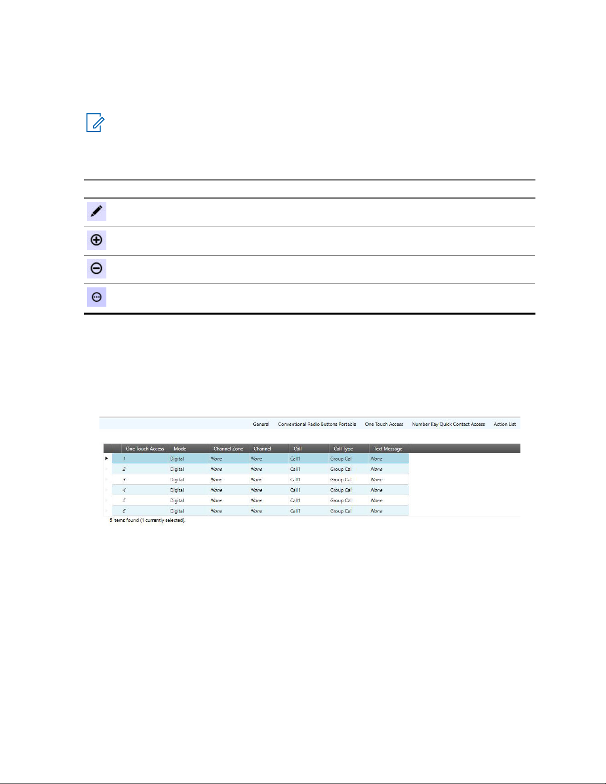
MN006055A01-AD
Chapter 1: Introduction to Customer Programming Software (CPS) 2.0
Operational Buttons in CPS 2.0
The operational buttons allows the user to manage the radio data. These buttons appear above List
Item tables within a Set.
NOTICE: If a button is not enabled for the selected row, then the requested operation is not
supported. Some areas in the programming pane may only allow for a single operation, such as
export.
Table 8: Operational Buttons in CPS 2.0
Button Description
The Edit button is used to modify the properties for the selected row.
The Add button is used to add items to the table.
The Delete button is used to remove the selected item from the table.
The 3-dot button provides more options. The options that are available from
this button vary.
Row Selection in CPS 2.0
The selection of items is performed by hovering the pointer to the left of the relevant row and clicking
the left mouse button. Hovering the pointer over the first column in a row changes the pointer from a
standard pointer to a hand pointer. The SHIFT and CTRL keys are used to select a range of rows or
selective rows. Selected rows are highlighted.
Figure 9: Example of Selected Row
Search Feature in CPS 2.0
The Search field in the programming pane allows the user to search for content within the table. The
search feature searches through every cell in the table and only displays rows that contain some or all
of the search criteria.
Arrange and Hide Columns in CPS 2.0
Columns in the programming pane can be arranged by dragging any column by the header section to a
new location. Once a column is selected and dragged, arrows appear above and below the header
section to indicate the new location.
The columns displayed in the programming pane can be hidden to show only those columns of data
that are relevant. To hide columns, right any column in the header section to open the Field Chooser
window and select only the relevant fields to display.
75

MN006055A01-AD
Chapter 1: Introduction to Customer Programming Software (CPS) 2.0
Fill Down
To quickly copy the value of a cell to the cells underneath it, select a source cell, hold down Shift,
select the target cells under the source cells, right click on the selected cells, and select Fill down in
the context menu. The contents of the source cell will be copied into the selected cells.
1.1.4
Information Windows in CPS 2.0
The CPS 2.0 provides information windows along the bottom of the application. By default, these
information windows are hidden, where only the names are visible in tabs.
The following windows are supported:
• Validation Results Window on page 76
• Warning Messages Window on page 77
• Search Results Window on page 77
• Help Window on page 78
These information windows provide the user with important and helpful details about operations
performed in the application.
NOTICE: The tabs that appear are dependent on the current view of the application.
Expand and Auto Hide Information Windows
To expand information windows, click the relevant tab. The window automatically hides once the user
clicks outside the window.
To pin the information window content to the application, select the horizontal Auto Hide pin icon
in the upper right-hand corner of the window.
Dock or Float Information Windows
Once a window is pinned to the application, the user can dock the window to a dockable area of the
application or allow the window to float anywhere on the screen. To dock a window, click and drag the
window by the blue header section over a docking square and release. Docking squares appear in the
application once the user drags a window.
To allow the window to float on the screen, simply drag, and drop the window to an area other than a
docking square.
1.1.4.1
Validation Results Window
The Validation Results window displays error conditions within the configuration.
NOTICE: The Validation Results window only appears when a Configuration is being edited.
NOTICE: Help for error-related items can be launched by selecting the row with the error and
pressing the F1 key.
The following columns are available from the Validation Results table:
Path
Path within the Configuration to the field containing the error.
76

MN006055A01-AD
Chapter 1: Introduction to Customer Programming Software (CPS) 2.0
Error Code
An internal error code that identifies the error within the system.
Description
A description that provides details to the user as to the cause of the error.
Actions
When a curly icon (Reset Value) is displayed in the Actions column, the validation error can be
automatically resolved by clicking the icon. The user is taken to the Set associated with the error.
The field with the error is highlighted in red.
The Reset All (For Selected Top Set) button allows the user to reset all validation errors that found in
the currently selected Top Set.
1.1.4.2
Warning Messages Window
The Warning Messages window will display warnings that occur in configurations. For example, if
CPS 2.0 cannot paste a value to a radio parameter, a warning will be added listing the parameter that
could not be pasted.
NOTICE: The Warning Messages window only appears when a Configuration is being edited.
1.1.4.3
Search Results Window
The Search Results window allows the user to search for fields and/or field values when editing
Configurations. This search feature allows the user to quickly locate fields within a Configuration
without having to know the Set.
NOTICE:
The Search Results window only appears when a Configuration is being edited.
When editing a configuration, the user enters a word, phrase, or value in the Search field. The x to the
right of the Search field is used to clear the search entry and the search results. The search icon ( )
is used to start the search. The drop-down arrow to the right of the Search field allows the user to
select from the previous 10 searches.
The following options are used to refine the search:
Name
When selected, the text entered in the Search field is searched against the name of all fields.
Value
When selected, the number or text entered in the Search field is searched against the value of all
fields.
Name and Value
When selected, both the field name and value are searched against the entry in the Search field.
Match whole word
When checked, the exact word, phrase, or value entered in the Search field is used to narrow the
search results.
The following columns provide details of the search:
Path
The path to the field within the Configuration in Set Name\Field Name format.
77

MN006055A01-AD
Chapter 1: Introduction to Customer Programming Software (CPS) 2.0
Value
The current value for the field.
NOTICE: Double-clicking any row in the search results opens the relevant Set and places the
focus on the field.
1.1.4.4
Help Window
The Help window is used to display context-sensitive help for fields used within Configurations and
Sets.
The Help window is used to display context-sensitive help for fields used within Configurations and
Sets.
NOTICE: The Help widow only appears when a Configuration is being edited.
When a user is editing a Configuration, help content is displayed in the Help window when a field is
selected within the Set. Pressing the F1 key opens the full help system with the current selected field in
focus.
Pressing the F1 key opens the full help system with the current selected field in focus.
1.2
CPS 2.0 Concepts
This section covers various key concepts employed by MOTOTRBO Customer Programming Software
(CPS) 2.0.
Key concepts of CPS 2.0 are listed in the following sections:
1.2.1
Sets and Configurations in CPS 2.0
Customer Programming Software (CPS) 2.0 uses configurations and set to organize radio identity and
radio parameters in a data structure that is saved into archives, read from radios, and written or cloned
into radios.
The following sections describe the concepts and editing of Sets and Configurations within CPS 2.0:
1.2.1.1
What are Sets and Configuration?
Customer Programming Software (CPS) 2.0 introduces the concept of Sets and Configurations for
programming and organizing radio fields.
Sets
A Set is a logical group of related radio fields. For example, the General Settings Set contains fields
that are not specific to a given radio feature, but generally apply to a radio. The CPS 2.0 application is
used to access and program radio fields within Sets.
Configurations
A Configuration is a collection of Sets. There are different types of Configurations, which are
associated with radio models, versions and options.
A CPS 2.0 archive file consists of radio specific data (model, version, options) and a configuration.
78

MN006055A01-AD
Chapter 1: Introduction to Customer Programming Software (CPS) 2.0
1.2.1.2
Copy and Paste Operation
MOTOTRBO Customer Programming Software (CPS) 2.0 supports copying pasting radio set
parameters across the following applications:
• MOTOTRBO CPS 2.0 to MOTOTRBO CPS 2.0.
• MOTOTRBO CPS 2.0 to MOTOTRBO Radio Management (RM) Configuration Client.
This feature allows the user to copy the editable data from one configuration (source) and paste the
data on another configuration (target). The exchange of data between two configurations is performed
at a Set level.
When the user performs the Copy operation on a set/configuration node within the Set Categories
navigation page, the allowable files are copied to the Windows clipboard.
For example, a set/configuration is copied and contains fields A, B, C and D. For security reasons, field
D is not allowed to be copied. Therefore the data copied to the clipboard are fields A, B, and C only.
The paste operation on the Set Categories navigation pane copies the data from the clipboard to the
editable fields in the target set/configuration.
The Warning Messages tab displays an field that did not copy with the failure status/reason.
NOTICE: Multi-select Copy/Paste is only supported when the user selects multiple sets of the
same type and only pasting the data on the parent node of the same set type.
Named Sets and References
When pasting parameters that have a name or alias the parameters are matched in the source
configuration using the user-defined name. For example, the user chooses to copy a personality that
points to a transmit contact name “Call 1”, the value of the field is selected based on the available
contacts in the target configuration. If the target configuration does not contain the “Call 1” contact,
then contact name "Call 1" is set to NULL and is marked as invalid.
If the user pastes a set that has the same name as a set in the target configuration, CPS 2.0 overwrites
the existing set with the source set. Single instance sets are always overwritten with the copied data
1.2.2
Radio Identity Parameters
Depending on the model and features, the fields that constitute the identity of the radio are as follows:
• Radio Alias
• Radio ID
• Radio IP
• CAI Network
• WAVE 5000 Username
• WAVE 5000 Password
• 5 Tone ID
When performing a clone operation, a dialog box is presented to the user that lists the target radio
identity parameters. This prompt always reminds the user to provide values for the radio identity
parameters without having to find the parameters across several Sets.
When performing a clone express operation, the radio identity parameters in the archive are ignored
and the values in the target radio are preserved.
79

MN006055A01-AD
Chapter 1: Introduction to Customer Programming Software (CPS) 2.0
1.2.3
Codeplug Version Support
MOTOTRBO Customer Programming Software (CPS) 2.0 can perform the operations on the listed
radio types for the specified codeplug versions.
If the user cannot perform an operation due to the codeplug version of the device, upgrade the device
in MOTOTRBO Customer Programming Software (CPS) 1.0 to a codeplug version that is supported
according to the following table.
Radio Type Ope
n
Archiv
e
MOTOTRBO mobile/
portable
MOTOTRBO repeater 14.00.00 (R2.4) or greater.
MOTOTRBO 2.0 mobile/portable
MOTOTRBO 2.0 repeater
MOTOTRBO 2.0.5 mobile
Ope
n
CPS
1.0
Archiv
e
ReadWriteClone/
Clone
Express
13.02.00 (R2.4) or greater. Not suppor-
07.07.00 (R2.4) or greater.
01.00.00 (R2.4) or greater
07.07.00 (R2.4) or greater
License
Activation
Updat
e
ted.
• From:
03.00.11
(R2.1) or
greater.
• To:
07.07.00
(R2.4) or
greater.
Recover
MOTOTRBO SL 07.07.00 (R2.4) or greater.
MOTOTRBO Light 07.07.00 (R2.4) or greater.
80
• From:
04.00.09
(R2.2) or
greater.
• To:
07.07.00
(R2.4) or
greater.

MN006055A01-AD
Chapter 1: Introduction to Customer Programming Software (CPS) 2.0
1.2.4
CPS 2.0 Archive File Support
MOTOTRBO Customer Programming Software (CPS) 2.0 supports opening the following archive files:
Table 9: MOTOTRBO Archive File Types
File format Description
.ctb2
.ctb
.xpba
1.2.5
MOTOTRBO CPS 2.0 archive. All archives saved in MOTOTRBO CPS 2.0
have the .ctb2 file extension. MOTOTRBO CPS 2.0 can open the .ctb2
files and the user can import .ctb2 files as radios in the MOTOTRBO Radio
Management Configuration (RMC) Client.
MOTOTRBO CPS 1.0 file format. In order for MOTOTRBO CPS 2.0 to
open .ctb files, the user must install a version of MOTOTRBO CPS 1.0.
It is recommended that the MOTOTRBO CPS 16.0 or greater is used.
MOTOTRBO RM archive, created by exporting a radio in the RMC Client.
MOTOTRBO CPS 2.0 can open the .xpba files but cannot save files in
the .xpba format.
Licensing Radio and Application Features
The user can purchase radio features through the Motorola Online (MOL) website. After the radio
features are purchased, an Entitlement ID (EID) is provided. Keep the EID in a safe place because the
EID is used to identify the licensed features and is necessary for enabling those features in the device.
A two-step process must be followed to enable a feature:
Registration
During Registration, the user associates the licensed features with all the devices on which they
want to enable the feature.
NOTICE: Internet connection is required. After Registration is complete, the licensed radio
features are ready to be activated on the registered devices.
Activation
During Activation, connect the device to the same PC on which the device was registered or the
license was downloaded using the Recovering Device Licenses on page 68 process.
IMPORTANT: If the device Serial Numbers are registered within an office, but the actual
devices are in the field, it is necessary to use a computer that can be brought out to the
devices in the field, such as a laptop.
After Activation is complete, the feature is enabled in the device and ready to be configured via
CPS.
To determine which features are available for purchase, perform a read operation on the device and go
to the top configuration node under Set Categories.
NOTICE: When installing MOTOTRBO CPS 2.0 any device licenses registered using CPS 1.0
will be transferred to CPS 2.0. After installation of CPS 2.0 any device licenses registered in
CPS 1.0 will not automatically be available in CPS 2.0. For those licenses to be available in
CPS 2.0 use the Recovering Device Licenses on page 68 process.
81

MN006055A01-AD
Chapter 1: Introduction to Customer Programming Software (CPS) 2.0
1.2.6
Application Log
CPS 2.0 creates a log of operations peformed, errors that occurred, and performance issues.
The log is saved locally in %programdata%\Motorola\MOTOTRBO CPS 2.0\Log. The log contains
errors such as failing to import a voice announcement file, failure during any device operation, or a
failure with the application itself.
To help characterize and resolve issues, the user can enable upload of the log to a remote server for
Customer Support and engineers to view. The log is uploaded for the following events:
• An error occurs.
• The application is launched.
• The application is closed.
The user is prompted at the launch of the CPS 2.0 to enable upload of the application log. The user
can also enable or disable upload of the log in the menu bar by selecting Tools→Settings. Then
select Log.
1.3
Common Tasks in Customer Programming Software (CPS) 2.0
This section covers various common scenarios for Customer Programming Software (CPS) 2.0.
The following sections contain helpful common tasks information:
1.3.1
Using Clone to Deploy a New Fleet of Radios
Out of the box, every radio is configured with the same radio identity parameters. To have an effective
MOTOTRBO system each radio should have its own unique identity. The Clone operation can be used
to quickly deploy a new fleet of radios or to add new radios to deployed fleet.
When and where to use:In MOTOTRBO CPS 1.0 to ease deployment of a fleet of radios the user
would go to Edit→Preferences and would enable the Clone Identity feature. This allows the user to
edit the Radio ID, Radio Alias, and any other unique parameters and then Clone the codeplug to the
radio. To perform the same operation in CPS 2.0, follow these steps.
Procedure:
1 Open the source archive that will be cloned into the new fleet of radios.
2 Connect a similar model target radio that has a different serial number than what is in the source
archive.
3 Click on the Clone button in the actions bar.
4 In the Connected Devices dialog select the target radio.
The Clone dialog appears displaying all the Radio Identity Parameters on page 79 from the
source archive file.
5 Fill in the desired values for the target radio.
6 Click the Clone button within the Clone dialog.
7 A progress bar appears detailing status of the clone operation.
82

MN006055A01-AD
Chapter 1: Introduction to Customer Programming Software (CPS) 2.0
8 Once the clone successful message appears: disconnect the radio, connect a new radio, and
repeat steps 3-8.
All new radios is deployed with unique identity parameters. Unlike CPS 1.0, the user does not have to
worry if the Clone Identity preference was set correctly.
1.3.2
Using Clone Express to Modify Shared Parameters in a Deployed Fleet
In a deployed fleet of radio, meticulous planning and programming was performed to ensure that each
radio was configured with unique radio identity parameters. The user of CPS 2.0 wants to ensure that
any further updates of shared parameters does not overwrite the radio identity parameters in the
deployed fleet.
When and where to use:In MOTOTRBO CPS 1.0, the CPS user would go to Edit→Preferences amd
would disable the Clone Identity feature. This would allow the user to overwrite the shared parameters
of a source archive without overwriting the Radio Identity Parameters on page 79 in the target radios.
In order to perform the same operation in CPS 2.0 perform the following steps.
Procedure:
1 Open the source archive that will be cloned into the deployed fleet of radios.
2 Connect a similar model target radio that has a different serial number than what is in the source
archive.
3 Click on the Clone Express button in the actions bar.
4 In the Connect Devices dialog select the target radio.
5 Unlike the clone operation, the Clone dialog will not appear. Instead a progress bar appears
detailing status of the clone express operation. CPS 2.0 will read out the radio identity
parameters of the target radio and merge them with the source codeplug. Then it will write the
merged codeplug to the target devices.
6 Once the clone express successful message appears: disconnect the radio, connect a new
radio, and repeat steps 3-5.
All radios programmed will now have the new shared parameters from the source archive but each
radios' identity parameters will be retained. Unlike CPS 1.0, the user does not have to worry if the
Clone Identity preference was set correctly.
1.3.3
Retrieving Firmware and Codeplug Update Package
In order to perform Update and Recover operations using MOTOTRBO CPS 2.0 the desired update
package must be downloaded and installed on the PC performing the operations.
When and where to use:Previously installed System Release 2.4 and greater update packages, used
with CPS 1.0, can be used with CPS 2.0. The below steps only need to be performed for update
packages that are not already installed.
Procedure:
1 Launch the web browser.
2 Log on to the Motorola Solutions Online (MOL) website.
3 Click the Resource Center link.
4 In the search area, type MOTOTRBO.
5 From the Available List window, Select the update package.
83

MN006055A01-AD
Chapter 1: Introduction to Customer Programming Software (CPS) 2.0
6 Save the update package (compressed or zipped) onto the desktop.
7 Extract the compressed file.
8 Run the install executable extracted from the compressed update package.
9 After the install completes the update package is available for use in the Update and Recover
operations.
1.4
Differences between CPS 2.0 and CPS 1.0
The below sections list key differences between MOTOTRBO CPS 1.0 and CPS 2.0.
1.4.1
Features Not Supported in CPS 2.0
Below is the list of features that were available in Customer Programming Software (CPS) 1.0 but are
not supported in CPS 2.0.
Radios or Archives on System Releases Prior to 2.4.
CPS 2.0 and Radio Management (RM) Configuration Client cannot open archives or perform
operations on radios that are on system release prior to 2.4. If you do not wish to upgrade these radios
to system release 2.4 or higher please continue to use CPS 1.0 to configure them. See Codeplug
Version Support on page 80 for the codeplug versions and radio types CPS 2.0 supports.
IP Repeater Programming
IP Repeater Programming is not supported in CPS 2.0. For users who have repeaters on system
release 2.10 or greater, please use RM to perform IP Repeater Programming operations.
Bluetooth Programming
Bluetooth programming is not supported in CPS 2.0.
Undo/Redo
Undoing and redoing radio parameter changes is not supported in CPS 2.0.
Drag Drop
CPS 2.0 does not support the ability to drag a set or configuration from one application instance of
CPS 2.0 and drop the set or configuration into another application instance of CPS 2.0. Using the copy
and paste operations has the same effect as drag drop.
Expert/Basic/Custom Views
CPS 1.0 allowed the user to selectively choose Basic View where only a small set of radio parameters
were visible in the CPS UI, Expert View where all radio parameters were visible in the UI, and Custom
View where the user could define which parameters are visible in the UI. CPS 2.0 only supports the
equivalent of Expert View, where all radio parameters are visible.
3600 Trunking Subscribers
CPS 2.0 does not support 3600 Trunking radios or archives. Continue to use CPS 1.0 to configure
3600 trunking radios.
84

MN006055A01-AD
Chapter 1: Introduction to Customer Programming Software (CPS) 2.0
Detailed and Customer Handout Expanded Reports
CPS 2.0 does not allow the user to generate detailed archive reports or customer handout expanded
reports.
Multiple Selection
At this time CPS 2.0 does not support operations on more than one row element within a List Item
Table at a time. Also, performing operations on multiple sets at time is not supported.
1.4.2
Multiple Document Support
MOTOTRBO CPS 1.0 allowed the user to open several archive documents in the same CPS 1.0
application instance. MOTOTRBO CPS 2.0 only allows the user to open one archive document at a
time per CPS 2.0 application instance.
To view multiple CPS 2.0 archive documents at once, the user can launch multiple application
instances of CPS 2.0 by performing one of the following operations:
• Right-click an open instance of CPS 2.0, in the Windows taskbar, and select MOTOTRBO CPS 2.0.
• Open the Windows start menu, navigate to the Motorola applications folder, and select MOTOCPS
2.0.
• Double click on the MOTOTRBO CPS 2.0 application shortcut on the desktop.
As CPS 2.0 can only have one archive open at a time there is a change in the read and open
operations. If an archive is already open and the user tries to open a new archive or read a radio, the
currently opened archive closes and is replaced with the newly opened/read archive. If the open
archive had not been saved, the user is prompted to save or discard the archive before the new
archive is opened.
1.4.3
Configuring Voice Announcements and Language Packs
In MOTOTRBO CPS 1.0, adding and removing language packs or voice announcements were
individual operations that had to be performed on each radio. In MOTOTRBO CPS 2.0, adding and
removing language packs and voice announcements are done inside the configuration and are added
or removed as part of the Write/Clone/Clone Express operations.
See the following sections for more information.
1.4.3.1
Loading a Language Pack
Perform the following steps to load different language packs into the radio.
Prerequisites:
Procedure:
1 Open a source archive that will be written or cloned to the desired target radio.
2 From the Set Categories tab, select General→Language Pack set.
The Language Packs set is displayed.
3 Click
4 In the Add Language Packs window, select the desired language.
.
85

MN006055A01-AD
Chapter 1: Introduction to Customer Programming Software (CPS) 2.0
Select multiple languages by pressing the CTRL key while clicking the desired languages.
5 Click OK.
6 Perform a Write/Clone/Clone Express operation on the target radio to load the added language
packs.
NOTICE: Even if the identification (ID) of the language pack in the source and the
destination are the same, the Customer Programming Software (CPS) 2.0 always
overwrites the language pack.
If the user selects multiple language packs that have the same language pack ID but with
different version numbers, CPS loads the language packs with the higher version.
The archive opened must be for a display model.
This task does not apply to repeaters.
If the radio has at least one language pack loaded, the language pack information is
displayed in the Language Pack set the next time the user reads the radio.
1.4.3.2
Deleting a Language Pack
Perform the following steps to remove unwanted language packs from the radio.
Prerequisites:
Procedure:
1 Open a source archive that will be written or cloned to the desired target radio
2 From the Set Categories tab, select General→Language Pack set.
The Language Packs set is displayed.
3 In the Language Packs List table, select the unwanted language.
Select multiple languages by pressing the CTRL key while clicking the desired language.
4 Right click and select Delete.
5 Perform a Write/Clone/Clone Express operation on the target radio to delete the language packs
removed from the configuration.
NOTICE:
The archive opened must be for a display model.
This task does not apply to repeaters.
1.4.3.3
Loading Voice Announcement Files
Perform the following steps to load voice announcement files to a radio.
When and where to use:Voice Announcement files must be imported into CPS 2.0 before they can be
selected in a configuration. See Importing Voice Announcement Files on page 71.
Procedure:
1 Open a source archive that will be written or cloned to the desired target radio.
2 From the Set Categories tab, select General→Voice Announcement set.
3 Under the General topic set Announcement Type to Voice Announcement Files.
4 Above the Files List table, click
86

MN006055A01-AD
Chapter 1: Introduction to Customer Programming Software (CPS) 2.0
5 In the Add Voice Announcement dialog select the imported voice announcement files to add to
the device.
6 Click OK.
7 Assign the added voice announcement files to the channels, zones, or features the user desires
the radio to announce.
8 Perform a Write/Clone/Clone Express operation on the target radio to add the voice
announcement files and to configure the announcement settings.
1.4.3.4
Deleting a Voice Announcement
Perform the following steps to remove voice announcement files from a radio
Procedure:
1 Open a source archive that will be written or cloned to the desired target radio.
2 From the Set Categories tab, select General→Voice Announcement set.
3 Navigate to the File List table.
4 Select the voice announcement files to be removed from the target device. Use Shift and CTRL
keys to multiple select files.
5 Click
6 Fix any zones, channels, or features that were referencing the removed voice announcement
files.
7 Perform a Write/Clone/Clone Express operation on the target radio. Any voice announcement
file removed from the File List will be deleted from the device.
1.4.3.5
Removing Imported Voice Announcements
This procedure allows the user to remove imported voice announcements. Removed voice
announcements will no longer be selectable in the File List within the Voice Announcement Set
Procedure:
1 In the File List within the Voice Announcement set, open a Windows Explorer dialog.
2 In the address bar type %programdata%\Motorola\MOTOTRBO CPS 2.0\Voice
Announcement.
3 Select the files to be deleted.
4 Press the DEL on the keyboard or right-click the files and select Delete.
The deleted files are no longer selectable in the File List section of the Voice Announcement Set.
NOTICE: If deleted files are referenced within the File List of the Voice Announcement Set in a
CPS 2.0 archive, remove those files from the File List before any write or clone operations.
1.5
Troubleshooting in Customer Programming Software (CPS) 2.0
This section covers various troubleshooting scenarios for Customer Programming Software (CPS) 2.0.
WARNING: Only an experienced user should perform these troubleshooting activities.
87

MN006055A01-AD
Chapter 1: Introduction to Customer Programming Software (CPS) 2.0
The following sections contain helpful troubleshooting information:
1.5.1
Unable to Read or Write Codeplug to the Radio
If the user is unable to read the codeplug from the radio or write the codeplug to the radio, check the
following:
When and where to use:
• The programming cable is connected to the USB port and the radio.
• Ensure that the radio is powered up.
• For portable radios, ensure that the battery level is not low.
• Ensure that the network connection is established by checking if the network connection icon for the
MOTOTRBO radio appears in the Windows taskbar.
• If multiple MOTOTRBO devices are connected to the PC, ensure that the third octect of the Radio
IP on page 411 is unique. For example, a valid configuration would radio 1's Radio IP is configured
as 192.168.10.1 and radio 2's Radio IP is configured as 192.168.11.1. An invalid configuration
would be, radio 1's Radio IP is configured as 192.168.10.1 and radio 2's Radio IP is configured as
192.168.10.2.
• During write operation for MOTOTRBO conventional radios and MOTOTRBO 2.0 radios, ensure the
archive file met the following criterias:
- Check for Password is applicable and set to Read Only.
- Read/Write and Codeplug Password is set to blank.
• The model number in the device matches the supported devices.
• The user does not try to read a device that has a major codeplug version greater than the
supported codeplug version of the Customer Programming Software (CPS) 2.0.
• Ensure that a replacement board serial number is not detected on the device. This applies to both
boards on a dual board device.
• The MOTOTRBO driver is installed in the My Computer\System Properties\Hardware
\Device\Manager\Network Adapters.
• If the driver is not installed, double-click the Motorola LTD Devices and update the driver from the
Driver tab. See Installing MOTOTRBO Driver Windows 7 and Later on page 89.
1.5.2
Unable to Recover a Radio
If the user is unable to recover a radio, check the following:
When and where to use:
• Ensure that the programming cable is connected to the Universal Serial Bus (USB) port and the
radio.
• Ensure that the radio is turned on.
88

MN006055A01-AD
Chapter 1: Introduction to Customer Programming Software (CPS) 2.0
• Ensure that a replacement board serial number is not detected on the device. This sentence applies
to both boards on a dual board device.
1.5.3
Installing MOTOTRBO Driver Windows 7 and Later
The user is prompted to install the MOTOTRBO driver when the radio is connected to the PC for the
first time. The isntallation of the driver establishes a connection between the radio and the PC. This
procedure is for the Home and Business edition of Windows 7 and later.
Prerequisites:Exit all the MOTOTRBO programs running on the computer.
Procedure:
1 Connect one end of the programming cable to the radio and the other end to the universal serial
bus (USB) port of the PC.
2 Turn on the radio.
3 Follow the prompts in the Driver Software Installation window to install the driver.
4 Once the Driver Software Installation completes close the install dialog.
5 Perform any operation under the Device menu.
The MOTOTRBO driver installation is complete.
1.5.4
Installing FlashZap Driver on Windows Windows 7 and Later
The user is prompted to install the FlashZap driver when the user triggers the device update or recover
radio for the first time. This driver installation is required for the Customer Programming Software
(CPS) 2.0 Device Update and Recover feature to communicate with the repeaters in FlashZap or Boot
Mode. This procedure is for Windows 7 and later.
Prerequisites:Exit all the MOTOTRBO programs running on the computer.
Procedure:
1 Connect one end of the programming cable to the radio and the other end to the universal serial
bus (USB) port of the PC.
2 Turn on the radio.
3 On the Driver Software Installation window, click Close.
The installation is complete.
Postrequisites:Restart to the update or recover operations. See Updating a Radio on page 63 or
Recovering a Radio on page 64.
1.5.5
Communication Issues Due to Ethernet Properties
When a MOTOTRBO radio or repeater is connected to a PC it appears as a network interface. On
some PCs the ethernet properties of the radio's network interface can cause issues with CPS
Operations. When these problems occur it is recommended to disable unneeded ethernet properties.
Procedure:
1 Open configure the ethernet properties, by performing one of the following actions:
• Click Start→ Settings→ Network & Internet → Change adapter options.
• Click Start→ Control Panel→Network and Sharing Center → Change adapter settings.
89

MN006055A01-AD
Chapter 1: Introduction to Customer Programming Software (CPS) 2.0
2 Double-click the network connection named <Local Area Connection> that has the device
name <MOTOTRBO Radio>.
User can have more than one local area connection active on their machine. Ensure that the
right connection is selected.
3 In the Local Area Connection Status window, select Properties.
4 Under the This connection uses the following items:, uncheck all the check boxes except for
Internet Protocol (TCP/IPv4).
5 Click OK.
The setup for the MOTOTRBO local area connection is complete.
Postrequisites:The user must set up the MOTOTRBO LAN every time the MOTOTRBO driver
installation is required. See Installing MOTOTRBO Driver Windows 7 and Later on page 89.
90

MN006055A01-AD
Customer Programming Software (CPS) 2.0 Sets
Chapter 2
Customer Programming Software
(CPS) 2.0 Sets
The Customer Programming Software (CPS) 2.0 groups radio parameters into Sets. A Set is a
collection of radio parameters that define a specific radio feature (For example, General Settings or
Network). For MOTOTRBO, Sets are preselected and grouped into a Configuration for a specific
product family, such as MOTOTRBO Subscribers. The Sets that are preselected for Configurations
cannot be shared between other Configurations. For this reason, the configuration and modification of
parameters within a preselected Set must be performed within the relevant Configuration.
The following Sets are supported for MOTOTRBO:
2.1
Device Information
This section displays unique device specific information that is stored in the Customer Programming
Software (CPS) 2.0.
The following fields are supported:
2.1.1
Model Number
This read-only field displays a string of alphanumeric characters to represent the radio type.
Examples of model types include MOTOTRBO Non-Display Portable, MOTOTRBO Display Mobile with
GNSS, and MOTOTRBO Repeater.
This paragraph is applicable to MOTOTRBO Conventional radios. By default, when creating an IP Site
Connect system, the Model Number is blank and would always be blank unless it is programmed to be
updated to reflect the programmed repeater's model number.
2.1.2
Tanapa Number
This field displays a string of alphanumeric characters that is used for factory or distribution center
tracking and regional labeling.
2.1.3
Region
This field displays the codeplug region. CPS 2.0 can program radios from all regions.
2.1.4
Serial Number
This read-only field displays a string of unique alphanumeric characters to identify the radio.
This feature is applicable to MOTOTRBO Conventional radios.
91

MN006055A01-AD
Chapter 2: Customer Programming Software (CPS) 2.0 Sets
By default when creating a Link Establishment system, the Serial Number is blank and would always
be blank unless it is programmed to be updated to reflect the programmed model number for the
repeater.
2.1.5
Physical Serial Number
This read-only field displays a string of unique alphanumeric characters to identify the radio.
2.1.6
Firmware ID
The field displays an ID that uniquely identifies the radio firmware. Firmware ID can be used to
differentiate firmware for the same or different products.
2.1.7
Frequency Range (MHz)
This field displays the radio's frequency range.
The range is defined as being between, or equal to, the minimum and maximum frequencies, at which
the radio is allowed to operate.
2.1.8
Power Range (W)
This read-only field displays the power range in watts of the radio.
2.1.9
Power Range (W)
This read-only field displays the power range in watts for the 800 MHz and 900 MHz band of the radio.
NOTICE:
This feature is applicable for MOTOTRBO Conventional Mobile and Repeater 800/900 MHz.
2.1.10
12V Power Range (W)
This read-only field displays the 12V power range in watts of the radio.
2.1.11
24V Power Range (W)
This read-only field displays the 24V power range in watts of the radio.
2.1.12
Firmware Type
Displays the firmware type programmed in the radio.
The available firmware types are Analog and Digital.
• Analog: Analog only firmware
• Digital: Analog and digital firmware
92

MN006055A01-AD
Chapter 2: Customer Programming Software (CPS) 2.0 Sets
2.1.13
Firmware Type
Displays the firmware type programmed in the radio.
The available firmware types are Analog and Digital.
• Analog: Analog only firmware
• Digital: Analog and digital firmware
2.1.14
Firmware Version
This field displays the firmware version programmed in the radio.
Firmware is the software that controls the internal hardware components of the radio.
2.1.15
Codeplug Version
This field displays the codeplug version programmed in the radio.
Codeplug is the information (data) that supports the firmware and hardware configuration.
2.1.16
Bootloader Version
This field displays the bootloader version programmed in the radio.
The bootloader is the software component used to upgrade the firmware and codeplug of the radio.
2.1.17
Netmask
Typical network configuration parameters include the subnet mask (netmask) in addition to the IP
address.
Subnetting an IP network allows a single large network to be broken down into several logical smaller
ones by allocating bits from the host portion as the network portion. The subnet mask tells how many
bits identify the subnetwork, and how many bits provide room for the host addresses. The Netmask
value is not editable.
NOTICE:
For MOTOTRBO Conventional radios, this feature value is fixed at 255.255.255.0 irregardless
of the Radio IP address configuration.
2.1.18
Last Programmed Date and Time
The field displays the last date and time at which the radio was programmed.
2.1.19
MAC Address
Displays the MAC address or physical address for the repeater and the MOTOTRBO SLR Series
repeater.
93

MN006055A01-AD
Chapter 2: Customer Programming Software (CPS) 2.0 Sets
This address serves as a unique device identifier.
NOTICE:
This feature is applicable to MOTOTRBO Conventional radios in Digital mode only.
2.1.20
Wi-Fi MAC Address
Displays the Wi-Fi MAC address or physical address for the repeater and the MOTOTRBO SLR Series
repeater.
This address serves as a unique device identifier.
NOTICE:
If a unique WiFi MAC address is not encountered during a Read job (for example, FF-FF-FFFF-FF-FF, 00-00-00-00-00-00), enable the WiFi feature on the radio and repeat the Read job.
When successful, a unique WiFi MAC address (for example, 4C-CC-34-22-38-C6) is displayed.
This feature is applicable to MOTOTRBO Conventional radios in Digital mode only.
2.1.21
Controller FPGA Version
Displays the version of the Field Programmable Gate Array (FPGA) software image that is built in the
controller board of a MTR3000 base radio/repeater.
2.1.22
Wireline FPGA Version
Displays the version of the Field Programmable Gate Array (FPGA) software image that is built in the
wireline card for a MTR3000 base radio/repeater with the Wireline board installed.
2.1.23
RX Frequency Range (MHz)
Displays the RX frequency range for the radio.
The range is defined as being between, or equal to, the minimum and maximum frequencies, at which
the radio is allowed to operate.
2.1.24
RX Frequency Range (MHz)
Displays the 800 MHz band and 900 MHz band RX frequency range for the MOTOTRBO Conventional
Repeater.
The range is defined as being between, or equal to, the minimum and maximum frequencies, at which
the radio is allowed to operate.
2.1.25
RX Frequency Range (MHz) (SL Series 800/900 MHz Radios)
Displays the RX frequency range for the radio.
The range is defined as being between, or equal to, the minimum and maximum frequencies, at which
the radio is allowed to operate.
NOTICE:
This feature is applicable for MOTOTRBO 2.0 SL Series 800/900 MHz radios.
94

MN006055A01-AD
Chapter 2: Customer Programming Software (CPS) 2.0 Sets
2.1.26
TX Frequency Range (MHz)
Displays the TX frequency range for the radio.
The range is defined as being between, or equal to, the minimum and maximum frequencies, at which
the radio is allowed to operate.
NOTICE:
This feature is disabled when the Voting Mode feature is set to Analog Satellite Receiver or
Digital Satellite Receiver. This feature is still disabled even though the user sets Voting Mode to
Normal Repeater or Digital Voting Repeater until the user reads a device with Voting Mode set
to those values.
2.1.27
TX Frequency Range (MHz)
Displays the 800 MHz band and 900 MHz band TX frequency range for the MOTOTRBO Conventional
Repeater.
The range is defined as being between, or equal to, the minimum and maximum frequencies, at which
the radio is allowed to operate.
NOTICE: This feature is disabled when the Voting Mode feature is set to Analog Satellite
Receiver or Digital Satellite Receiver. This feature remains disabled until the user sets Voting
Mode to Normal Repeater or Digital Voting Repeater and reads a device.
2.1.28
TX Frequency Range (MHz) (SL Series 800/900 MHz radios)
Displays the TX frequency range for the radio.
The range is defined as being between, or equal to, the minimum and maximum frequencies, at which
the radio is allowed to operate.
NOTICE:
This feature is disabled when the Voting Mode feature is set to Analog Satellite Receiver or
Digital Satellite Receiver. This feature is still disabled even though the user sets Voting Mode to
Normal Repeater or Digital Voting Repeater until the user reads a device with Voting Mode set
to those values.
This feature is applicable to MOTOTRBO 2.0 SL Series 800/900 MHz radios.
2.2
Welcome Bitmap Set
The Welcome Bitmap set is used to load an image that appears on the radio display when the radio is
turned on.
The following section contains all supported fields:
2.2.1
General (Welcome Bitmap)
The General section of the Welcome Bitmap set contains the following fields:
2.2.1.1
Welcome Image
Allows the user to load an image (bitmap) that is used as a Welcome screen for the radio.
95

MN006055A01-AD
Chapter 2: Customer Programming Software (CPS) 2.0 Sets
The Select button is used to select a bitmap image, while the Remove button is used to remove the
current image from the radio display.
The resolution and color depth for the image are as follows:
• 160 pixel (width) * 72 pixel (height) and 256 color for Mobile
• 132 pixel (width) * 90 pixel (height) and 256 color for Portable Full Keypad model
• 132 pixel (width) * 72 pixel (height) and monochrome color for Portable Limited Keypad model
• 132 pixel (width) * 90 pixel (height) for Handheld Control Head (HCH) mode
• 320 pixel (width) * 240 pixel (height) and 16-bit (R5-G6-B5) color for SL Series radios
NOTICE:
When the Welcome image is used, the Radio Name text is not displayed during the power up
sequence.
If the mobile radio is in HCH mode, the user cannot customize the Welcome Bitmap for HCH.
Therefore, the default Welcome image is used on the welcome screen regardless of the bitmap
image selection.
2.3
Language Packs Set
The Language Packs set is used to create a list of language pack sets that are used to assign to
radios. The user can add multiple sets of language packs by using the Language Pack List table.
The following fields are supported:
2.3.1
Language
Displays the language selected from a list of Language Packs.
Languages are added by selecting the Add icon. Once languages are selected from the Add
Language Packs window, they are added to the list of languages packs and removed from the Add
Language Packs window.
NOTICE: Languages in the Add Language Packs window are listed in their native language.
2.3.2
Locale
Displays the 4 character language code (i.e., en-us) for the selected language pack.
2.4
General Settings Set
The General Settings set allows you to configure general parameters for the radio.
2.4.1
General (General Settings)
This section explains the general setting for General set.
96

MN006055A01-AD
Chapter 2: Customer Programming Software (CPS) 2.0 Sets
2.4.1.1
Subscriber Inactivity Timer (SIT) (ms)
The Subscriber Inactivity Timer (SIT) controls how long the repeater will continue transmitting with
absence of subscriber activity on the uplink.
If the repeater is operating on shared-use frequencies, it cannot remain keyed indefinitely for the
benefit of broadcasting synchronization signals to subscriber units. The repeater will likely be de-keyed
most of the time; thereby requiring subscriber units to first activate the repeater (via the uplink
frequency) and acquire synchronization (via the downlink frequency) before completing the call setup
request and subsequent first transmission. The net result of these extra procedures is increased
access time; therefore, it is desirable to avoid these steps, whenever possible. There is a trade-off to
minimizing access time by keeping the repeater keyed for as long as practically possible, while
complying with the regulations regarding shared-use channels, which essentially require the repeater
to dekey when the channel is not in use. This can be balanced with the use of the Subscriber Inactivity
Timer.
The SIT timer starts when there is no inbound subscriber activity on either time slot (Slot 1 or 2) of a
repeater. When the SIT timer expires, the repeater will stop transmitting until awoken again by a
subscriber. To accommodate the reserved hang time after each transmission, the SIT timer should
always be equal or greater than the Hang Time (group, private, or emergency hang time; whichever
the longest) in the repeater. This will allow the reserved hang time and a short unreserved hang time
after each transmission prior to the repeater dekeying. If shared use is not a concern, the SIT timer can
be set to the maximum value. If shared use is a concern, the SIT timer should be set equal to or
slightly longer than the configured call hang timers.
For Connect Plus, the SIT value that is programmed with Customer Programming Software (CPS) 2.0
will be overwritten by the XRC when it establishes its link with the repeater. The SIT value is not
programmable in the Connect Plus Network Manager, but the XRC does consider other Network
Manager-configurable values (the Call Hang Timers) when setting the SIT. The repeater will use the
SIT value supplied by the XRC as long as it maintains connectivity to the controller. It is important to
know that always displays the CPS 2.0-configured value, even when connected to the XRC. The
repeater utilizes the CPS 2.0-configured value when it doesn’t have a connection to the XRC (such as
when the repeater is operating in Conventional Fallback mode).
For Capacity Plus–Single-Site and Capacity Plus–Multi-Site, the SIT should be set greater than the
longest hang timer to avoid the possibility of missing the Capacity Plus–Single-Site Status CSBK
transmitted at the end of a call. This ensures that the radio moves to either the rest channel or to
another active call of interest in the most efficient way possible.
Range:
Maximum Minimum Increment
7000 ms 1000 ms 500 ms
NOTICE:
This feature is disabled if Repeater Mode is set to Analog.
This feature is supported in Digital mode only.
2.4.1.2
Radio Alias
Sets an alias for the radio.
97

MN006055A01-AD
Chapter 2: Customer Programming Software (CPS) 2.0 Sets
When the radio is turn on, this alias shows up as the welcome text, if the Welcome Image on page 95
is not used. The user may enter up to a maximum of 16 characters. Valid characters are
alphanumerics, spaces and special characters. This is a radio-wide feature.
NOTICE:
This feature is not applicable for SL Series Commercial radios.
To preserve the current value of this feature in the radio and ignore the archive identity feature
value during cloning, see Express Cloning a Radio on page 62.
This feature is supported in Digital mode only.
2.4.1.3
Radio ID
Sets an individual ID that uniquely identifies the radio.
This ID is used by other calling radios when addressing the radio, for instance, when making a private
call or sending a text message. In the IP Site Connect system, this ID is used to uniquely identify the IP
Site peers and the IP Site masters. For a radio that is used as an IP data gateway control station, it is
recommended that the Radio ID be set to 16448250 as this number translates to an easy-to-remember
radio air interface network IP of 12.250.250.250. If multiple IP data gateway control stations are
required in the system, they can be assigned alternative numbers so long as the numbers are unique
to each of them. This is a radio-wide feature.
Range:
Maximum Minimum Increment
16776415 (for Non-Capacity Plus system), 65535 (for Capacity Plus Single Site and Multi-Site System)
NOTICE:
To preserve the current value of this feature in the radio and ignore the archive identity feature
value during cloning, see Express Cloning a Radio on page 62.
This feature is supported in Digital mode only.
2.4.1.4
1 1
GNSS
Global Navigation Satellite System (GNSS) is a satellite navigation system that is used to determine a
radio's precise location.
This feature allows the dispatcher to monitor a radio's current position. The required GNSS hardware is
built into the radio on GNSS equipped models.
NOTICE:
This feature is applicable to MOTOTRBO Conventional radios in Digital mode only.
This feature is available only for GNSS models.
2.4.1.5
GNSS
This drop-down list allows you to choose the global navigation satellite system for the radio.
The possible choices depend on the GNSS hardware available in the radio. The choices may be a
combination of GNSS, GLONASS, Beidou, Galileo, and QZSS (in that order and separated by
98

MN006055A01-AD
Chapter 2: Customer Programming Software (CPS) 2.0 Sets
slashes). If there are two chips in the radio that supports those combinations, you may have GNSS/
GLONASS, Beidou/QZSS as the choices.
NOTICE:
This feature is grayed out when GNSS is unchecked.
2.4.1.6
Private Calls
This field allows you to enable or disable the initiation of a Private Call on a digital channel.
When disabled, a prohibit tone will sound when the user tries to initiate a Private Call. You can
continue to receive and respond to Private Calls, and is still able to initiate Call Alerts. This is a radiowide feature.
NOTICE:
This feature is supported in Digital mode only.
This feature is not applicable for Capacity Max system.
2.4.1.7
Site Search Timer (sec)
This field allows you to adjust the value of the Site Search Timer.
The timer begins immediately after an Active Site Search has identified the nearest available site, and
allows a period of time for you to use the Site Lock feature, or to repeat the Active Site Search to find
the next available site. When the timer expires, the radio reverts back to auto roam if the Site Lock
feature is disabled. This is a radio-wide feature.
Range:
Maximum Minimum Increment
255 sec 0 sec 1 sec
NOTICE:
This feature is supported in Digital mode only.
2.4.1.8
ARS Initialization Delay (min)
This field allows you to configure the duration of the random range delay before an Automatic
Registration Service (ARS) registration.
When many radios, for instance a hundred radios, power up at the same time, channel collisions will
happen and it will take a long time for all the radios to register successfully. The user can avoid this by
configuring different delay durations for the radios. For example, setting the timer to 0 minute
corresponds to the radio using a random timer from 5 to 15 seconds to send the ARS. Setting the timer
to 30 minutes corresponds to the radio using a random timer from 5 seconds to 30 minutes to send the
ARS. Setting the timer to 60 minutes corresponds to the radio using a random timer from 5 seconds to
60 minutes to send the ARS, and so forth. This is a radio-wide feature.
Range:
Maximum Minimum Increment
240 min 0 min 30 min
NOTICE:
This feature is supported in Digital Mode only.
99

MN006055A01-AD
Chapter 2: Customer Programming Software (CPS) 2.0 Sets
2.4.1.9
TX Preamble Duration (ms)
Preamble is a string of bits added in front of a data message or control message (Text Messaging,
Location Messaging, Registration, Radio Check, Private Call, and other data message or control
message) before transmission.
This preamble prolongs the message in order to reduce the chances of the message being missed by
the receiving radio. The Transmit (TX) Preamble Duration sets the duration of the preamble. This
duration needs to be increased as the number of scan members increases on the target radio (refer to
the MOTOTRBO System Planner for guidance on how to set the duration). This value can be
increased in all the transmitting radios if scanning radios are often missing data messages. However, a
larger preamble occupies the channel longer. Therefore, increasing the Transmit Preamble duration
will increase the success rate of data received while other radios are scanning, but will decrease the
amount of data that can be transmitted on the channel. This is a radio-wide feature.
Range:
Maximum Minimum Increment
8640 ms 0 ms 60 ms
NOTICE:
The TX Preamble feature is disabled if the duration is set to 0.
If the Portable is configured in single site conventional repeat mode and Battery Saver is
disabled, this feature should not be set to 0. This recommendation applies if MTR base radios/
repeaters are being used in single site conventional system.
This feature is supported in Digital mode only.
2.4.1.10
Voice Pretime Duration
This field allows you to configure call setup duration by allowing you to add a pretime burst
transmission to the call.
This duration allows radios, with Scan enabled, enough time to connect to the channel before audio is
transmitted.
The following table lists the recommended Voice Pretime Duration setting:
Table 10: Recommended Voice Pretime Duration
Radios with Scan Enabled Voice PreTime Duration (ms)
TPT Disabled Direct Mode/Repeater Mode
(TPT Enabled)
1 n/a n/a
2 120 60
3 240 180
4 300 240
5 420 360
6 540 480
7 660 600
8 720 660
100
 Loading...